

Page 1
Pico Controllers
Bulletin 1760
User Manual
Page 2
Important User Information
Solid state equipment has operational characteristics differing from those of
electromechanical equipment. Safety Guidelines for the Application,
Installation and Maintenance of Solid State Controls (Publication SGI-1.1
available from your local Rockwell Automation sales office or online at
http://www.ab.com/manuals/gi) describes some important differences
between solid state equipment and hard-wired electromechanical devices.
Because of this difference, and also because of the wide variety of uses for
solid state equipment, all persons responsible for applying this equipment
must satisfy themselves that each intended application of this equipment is
acceptable.
In no event will Rockwell Automation, Inc. be responsible or liable for
indirect or consequential damages resulting from the use or application of
this equipment.
The examples and diagrams in this manual are included solely for illustrative
purposes. Because of the many variables and requirements associated with
any particular installation, Rockwell Automation, Inc. cannot assume
responsibility or liability for actual use based on the examples and diagrams.
No patent liability is assumed by Rockwell Automation, Inc. with respect to
use of information, circuits, equipment, or software described in this manual.
Reproduction of the contents of this manual, in whole or in part, without
written permission of Rockwell Automation, Inc. is prohibited.
Throughout this manual, when necessary we use notes to make you aware of
safety considerations.
WARNING
IMPORTANT
ATTENTION
SHOCK HAZARD
BURN HAZARD
Identifies information about practices or circumstances
that can cause an explosion in a hazardous environment,
which may lead to personal injury or death, property
damage, or economic loss.
Identifies information that is critical for successful
application and understanding of the product.
Identifies information about practices or circumstances
that can lead to personal injury or death, property
damage, or economic loss. Attentions help you:
• identify a hazard
• avoid a hazard
• recognize the consequence
Labels may be located on or inside the equipment (e.g.,
drive or motor) to alert people that dangerous voltage may
be present.
Labels may be located on or inside the equipment (e.g.,
drive or motor) to alert people that surfaces may be
dangerous temperatures.
Page 3
Summary of Changes
The information below summarizes the changes to this manual since
the last printing as publication 1760-UM001C-EN-P, April 2005.
To help you locate new and updated information in this release of the
manual, we have included change bars as shown to the right of this
paragraph.
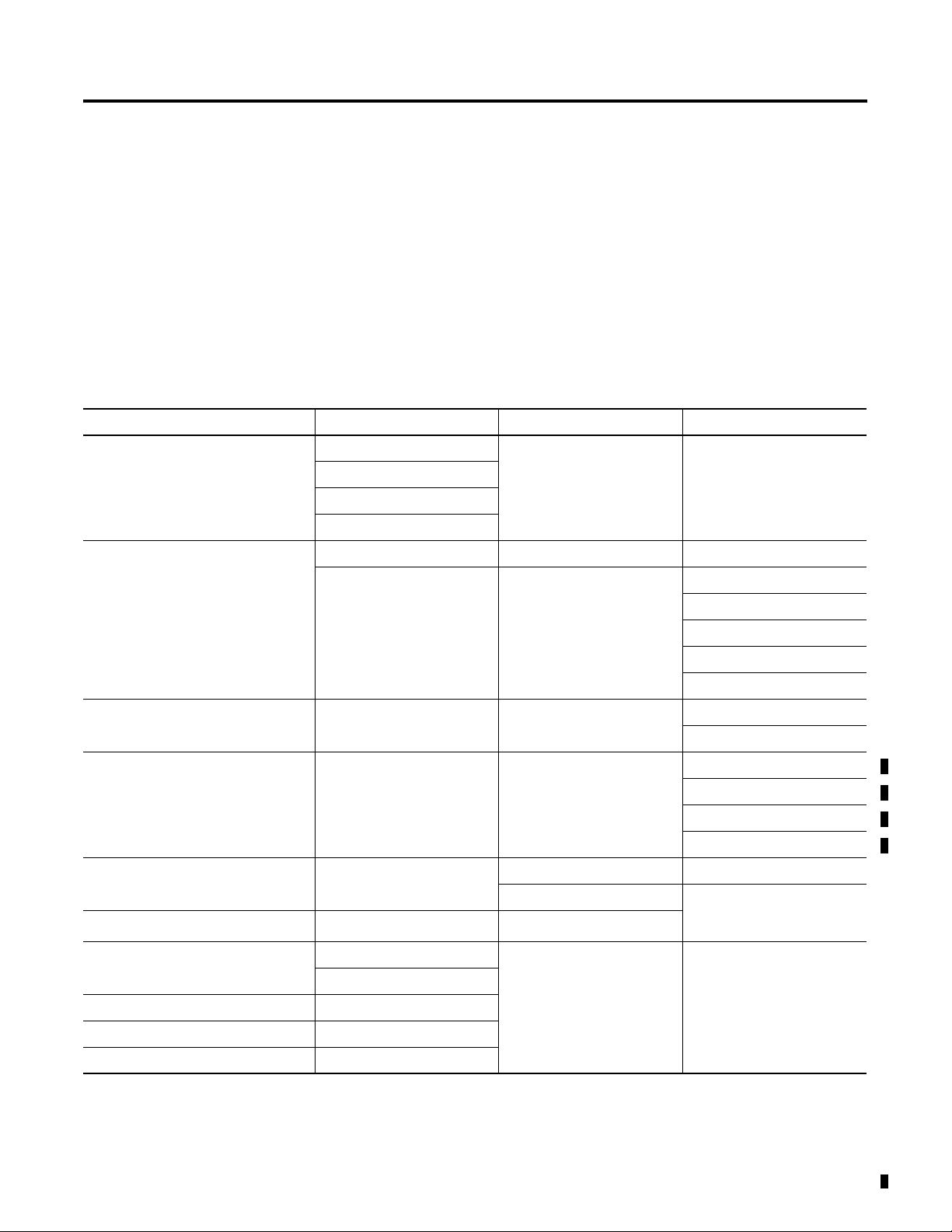
Catalog Number Release
The following table shows the history of Pico catalog numbers.
History
Description Released June 2000 Release August 2001 Release March 2005
120/240V ac Pico 1760-L12AWA 1760-L18AWA-EX 1760-L18AWA-EXND
1760-L12AWA-NC
1760-L12AWA-ND
1760-L18AWA
24V dc Pico 1760-L12BWB 1760-L12BWB-ND 1760-L12BBB
1760-L12BWB-NC 1760-L18BWB-EX 1760-L12BBB-ND
1760-L18BWB-EXND
1760-L18DWD-EX
1760-L20BBB-EX
1760-L20BBB-EXND
12V dc Pico 1760-L12DWD 1760-L18DWD-EXND
1760-L12DWD-ND
24V ac Pico 1760-L12NWN
1760-L12NWN-ND
1760-L18NWN-EX
1760-L18NWN-EXND
Expansion Modules 1760-IA12XOW6I 1760-IA12XOW4I
1760-IB12XOB8 1760-IB12XOW6I
Expansion Module Connector
Memory Modules 1760-MM1 1760-MM2B
Input/Output Simulator 1760-SIM
Programming Software 1760-PICOSOFT
Programming Cable 1760-CBL-PM02
(1) Included with expansion module. Catalog Number is listed as a replacement part.
1 Publication 1760-UM001D-EN-P - September 2005
(1)
1760-MM2
1760-RPLCONN
Page 4
Summary of Changes 2
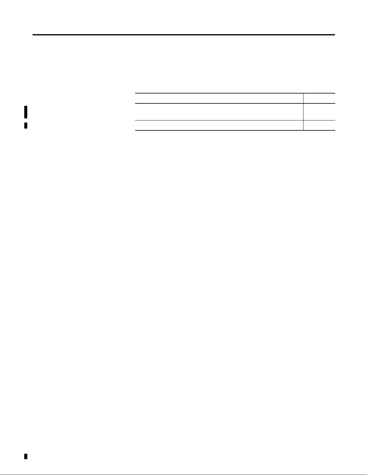
New Information
The table below lists sections where new information has been added.
For This New Information See
Changed Catalog Number 1760-L12NWA and 1760-L18NWA to
1760-L12NWN and 1760-L18NWN.
Changed inputs to 24V ac. page A-5
Throughout
manual
Publication 1760-UM001D-EN-P - September 2005
Page 5

Table of Contents
Preface
System Overview
Installation
Who Should Use this Manual. . . . . . . . . . . . . . . . . . . Preface-1
Purpose of this Manual . . . . . . . . . . . . . . . . . . . . . . . Preface-1
Common Techniques Used in this Manual . . . . . . . . . Preface-2
Rockwell Automation Support . . . . . . . . . . . . . . . . . . Preface-3
Chapter 1
Overview . . . . . . . . . . . . . . . . . . . . . . . . . . . . . . . . . . . . . 1-1
Hardware Versions . . . . . . . . . . . . . . . . . . . . . . . . . . . . . . 1-2
Operating Principles . . . . . . . . . . . . . . . . . . . . . . . . . . . . . 1-6
Chapter 2
Prevent Electrical Shock . . . . . . . . . . . . . . . . . . . . . . . . . . 2-1
European Communities (EC) Directive Compliance . . . . . . 2-2
Connect the Expansion Module . . . . . . . . . . . . . . . . . . . . . 2-3
Mount the Pico Controller . . . . . . . . . . . . . . . . . . . . . . . . . 2-3
Install the Remote Processor . . . . . . . . . . . . . . . . . . . . . . . 2-6
Wire Terminals . . . . . . . . . . . . . . . . . . . . . . . . . . . . . . . . . 2-8
Connect the Incoming Power . . . . . . . . . . . . . . . . . . . . . . 2-9
Use Surge Suppressors . . . . . . . . . . . . . . . . . . . . . . . . . . . 2-12
Connect the Inputs . . . . . . . . . . . . . . . . . . . . . . . . . . . . . . 2-14
Connect Outputs. . . . . . . . . . . . . . . . . . . . . . . . . . . . . . . . 2-22
Connect Relay Outputs . . . . . . . . . . . . . . . . . . . . . . . . . . . 2-22
Connect Transistor Outputs . . . . . . . . . . . . . . . . . . . . . . . . 2-24
Commission the Pico
Draw a Circuit Diagram with Pico
Chapter 3
Power On Unit . . . . . . . . . . . . . . . . . . . . . . . . . . . . . . . . . 3-1
Set the Menu Language . . . . . . . . . . . . . . . . . . . . . . . . . . . 3-2
Modes of Operation . . . . . . . . . . . . . . . . . . . . . . . . . . . . . 3-3
Create a Circuit Diagram (Program) . . . . . . . . . . . . . . . . . . 3-4
Chapter 4
Pico Operation . . . . . . . . . . . . . . . . . . . . . . . . . . . . . . . . . 4-1
Work with Contacts and Relays . . . . . . . . . . . . . . . . . . . . . 4-8
Function Relay Types . . . . . . . . . . . . . . . . . . . . . . . . . . . . 4-19
Example with Timing and Counter Relays . . . . . . . . . . . . . 4-21
Timing Relays . . . . . . . . . . . . . . . . . . . . . . . . . . . . . . . . . . 4-26
Counter Relays . . . . . . . . . . . . . . . . . . . . . . . . . . . . . . . . . 4-32
High Speed Counters . . . . . . . . . . . . . . . . . . . . . . . . . . . . 4-36
Time Switch . . . . . . . . . . . . . . . . . . . . . . . . . . . . . . . . . . . 4-42
Analog Comparators . . . . . . . . . . . . . . . . . . . . . . . . . . . . . 4-47
Text Display . . . . . . . . . . . . . . . . . . . . . . . . . . . . . . . . . . . 4-50
Jumps. . . . . . . . . . . . . . . . . . . . . . . . . . . . . . . . . . . . . . . . 4-53
Example Programs . . . . . . . . . . . . . . . . . . . . . . . . . . . . . . 4-55
i Publication 1760-UM001D-EN-P - September 2005
Page 6

Table of Contents ii
Save and Load Circuit Diagrams
Pico System Settings
Chapter 5
Interface to Memory Module and Programming Cable . . . . 5-1
Memory Module . . . . . . . . . . . . . . . . . . . . . . . . . . . . . . . . 5-2
PicoSoft . . . . . . . . . . . . . . . . . . . . . . . . . . . . . . . . . . . . . . 5-5
Chapter 6
Password Protection . . . . . . . . . . . . . . . . . . . . . . . . . . . . . 6-1
Change the Menu Language . . . . . . . . . . . . . . . . . . . . . . . 6-6
Change Parameters . . . . . . . . . . . . . . . . . . . . . . . . . . . . . . 6-7
Set Date, Time, and Daylight Saving Time . . . . . . . . . . . . . 6-9
Change Between Winter/Summer Time
(Daylight Saving Time) . . . . . . . . . . . . . . . . . . . . . . . . . . . 6-10
Activate Debounce (Input Delay). . . . . . . . . . . . . . . . . . . . 6-10
Activate and Deactivate P-Buttons . . . . . . . . . . . . . . . . . . . 6-11
Start-Up Behavior . . . . . . . . . . . . . . . . . . . . . . . . . . . . . . . 6-12
Set Cycle Time . . . . . . . . . . . . . . . . . . . . . . . . . . . . . . . . . 6-14
Retention . . . . . . . . . . . . . . . . . . . . . . . . . . . . . . . . . . . . . 6-15
Display Device Information . . . . . . . . . . . . . . . . . . . . . . . . 6-17
Retention
Inside Pico
Use of Expansion Modules
Troubleshoot Your Controller
Chapter 7
What is Retention?. . . . . . . . . . . . . . . . . . . . . . . . . . . . . . . 7-1
Set Retention . . . . . . . . . . . . . . . . . . . . . . . . . . . . . . . . . . 7-2
Delete Retentive Actual Values . . . . . . . . . . . . . . . . . . . . . 7-2
Transfer Retentive Behavior. . . . . . . . . . . . . . . . . . . . . . . . 7-3
Retentive Auxiliary Relays (Markers) . . . . . . . . . . . . . . . . . 7-4
Retentive Timing Relays . . . . . . . . . . . . . . . . . . . . . . . . . . 7-8
Retentive Up/Down Counters C7 and C8 . . . . . . . . . . . . . . 7-14
Chapter 8
Circuit Diagram Cycle . . . . . . . . . . . . . . . . . . . . . . . . . . . . 8-1
Determine Cycle Time of Circuit Diagrams. . . . . . . . . . . . . 8-3
Delay Times for Inputs and Outputs . . . . . . . . . . . . . . . . . 8-7
Chapter 9
Overview . . . . . . . . . . . . . . . . . . . . . . . . . . . . . . . . . . . . . 9-1
Operation . . . . . . . . . . . . . . . . . . . . . . . . . . . . . . . . . . . . . 9-2
Module Status Example . . . . . . . . . . . . . . . . . . . . . . . . . . . 9-5
Chapter 10
Messages from the Pico System . . . . . . . . . . . . . . . . . . . . . 10-1
Possible Situations When Creating Circuit Diagrams . . . . . . 10-2
Event . . . . . . . . . . . . . . . . . . . . . . . . . . . . . . . . . . . . . . . . 10-3
Publication 1760-UM001D-EN-P - September 2005
Page 7

DC Simulator
Specifications
Circuit Diagram Form
Table of Contents iii
Chapter 11
Description. . . . . . . . . . . . . . . . . . . . . . . . . . . . . . . . . . . . 11-1
Installation Guidelines. . . . . . . . . . . . . . . . . . . . . . . . . . . . 11-2
Appendix A
Physical Specifications. . . . . . . . . . . . . . . . . . . . . . . . . . . . A-1
Environmental Specifications . . . . . . . . . . . . . . . . . . . . . . . A-1
Electrical Specifications . . . . . . . . . . . . . . . . . . . . . . . . . . . A-2
Power Supply . . . . . . . . . . . . . . . . . . . . . . . . . . . . . . . . . . A-3
Inputs. . . . . . . . . . . . . . . . . . . . . . . . . . . . . . . . . . . . . . . . A-5
Outputs . . . . . . . . . . . . . . . . . . . . . . . . . . . . . . . . . . . . . A-10
Cycle Time . . . . . . . . . . . . . . . . . . . . . . . . . . . . . . . . . . . A-13
Dimensions. . . . . . . . . . . . . . . . . . . . . . . . . . . . . . . . . . . A-14
Appendix B
Glossary
Index
Publication 1760-UM001D-EN-P - September 2005
Page 8

Table of Contents iv
Publication 1760-UM001D-EN-P - September 2005
Page 9

Preface
Read this preface to familiarize yourself with the rest of the manual. It
provides information concerning:
• who should use this manual
• the purpose of this manual
• related documentation
• conventions used in this manual
• Rockwell Automation support
Who Should Use this Manual
Purpose of this Manual
Use this manual if you are responsible for designing, installing,
programming, or troubleshooting control systems that use Pico
controllers.
You should have a basic understanding of electrical circuitry and
familiarity with relay logic. If you do not, obtain the proper training
before using this product.
This manual is a reference guide for Pico controllers. It describes the
procedures you use to install, wire, and troubleshoot Pico.
Refer to publication 1760-GR001, Pico Controller Getting Results
Manual for a basic overview of Pico and an introduction to Pico
programming.
1 Publication 1760-UM001D-EN-P - September 2005
Page 10
Preface 2
Related Documentation
The following documents contain additional information concerning
Rockwell Automation products. To obtain a copy, contact your local
Rockwell Automation office or distributor.
For Read this Document Document Number
A basic overview of Pico and an introduction to Pico programming. Pico Controller Getting Results
Manual
In-depth information on grounding and wiring Allen-Bradley
programmable controllers
A description of important differences between solid-state
programmable controller products and hard-wired electromechanical
devices
An article on wire sizes and types for grounding electrical equipment National Electrical Code - Published by the National Fire
A complete listing of current documentation, including ordering
instructions. Also indicates whether the documents are available on
CD-ROM or in multi-languages.
A glossary of industrial automation terms and abbreviations Allen-Bradley Industrial Automation
Common Techniques Used in this Manual
The following conventions are used throughout this manual:
• Bulleted lists such as this one provide information, not
Allen-Bradley Programmable
Controller Grounding and Wiring
Guidelines
Application Considerations for
Solid-State Controls
Protection Association of Boston, MA.
Allen-Bradley Publication Index SD499
Glossary
1760-GR001
1770-4.1
SGI-1.1
AG-7.1
procedural steps.
• Numbered lists provide sequential steps or hierarchical
information.
Publication 1760-UM001D-EN-P - September 2005
Page 11

Preface 3
Rockwell Automation Support
Rockwell Automation offers support services worldwide, with over 75
Sales/Support Offices, 512 authorized Distributors and 260 authorized
Systems Integrators located throughout the United States alone, plus
Rockwell Automation representatives in every major country in the
world.
Local Product Support
Contact your local Rockwell Automation representative for:
• sales and order support
• product technical training
• warranty support
• support service agreements
Technical Product Assistance
If you need to contact Rockwell Automation for technical assistance,
please review the Troubleshooting section on page 10-1 in this
manual first. Then call your local Rockwell Automation representative.
You can also find a local Rockwell Automation Technical Support
contact at:
• http://support.automation.rockwell.com/contactinformation/
Your Questions or Comments on this Manual
If you find a problem with this manual, or you have any suggestions
for how this manual could be made more useful to you, please
contact us at the address below:
Rockwell Automation
Control and Information Group
Technical Communication, Dept. A602V
P.O. Box 2086
Milwaukee, WI 53201-2086
or visit our internet page at:
http://www.ab.com/pico or http://www.rockwellautomation.com
Publication 1760-UM001D-EN-P - September 2005
Page 12

Preface 4
Publication 1760-UM001D-EN-P - September 2005
Page 13

System Overview
Chapter
1
Overview
Pico is an electronic control relay with built-in logic, timer, counter,
and real-time clock functions. Pico is a control and input device that
can perform a variety of tasks in building and machine applications.
Pico is programmed using ladder diagrams. Each programming
element is entered directly via the Pico display. For example, you can:
• connect make and break contacts in series and in parallel,
• connect output relays and markers,
• define outputs as relays, flip-flop relays or latching relays,
• select timing relays with different functions,
• assign eight up and down counters,
• display text with variables,
• track the flow of current in the program, and
• load, save and password-protect programs.
Most controllers also offer a real-time clock, allowing up to 32
separate on and off times.
The dc versions can receive analog signals at two inputs and evaluate
the signals with eight analog comparators.
If you prefer to program Pico from a PC, use PicoSoft programming
software. PicoSoft allows you to create and test your programs on the
PC. It also enables you to print out your programs in DIN, ANSI or
Pico format.
1 Publication 1760-UM001D-EN-P - September 2005
Page 14
1-2 System Overview
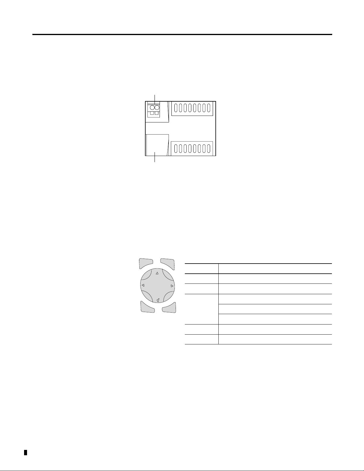
Hardware Versions
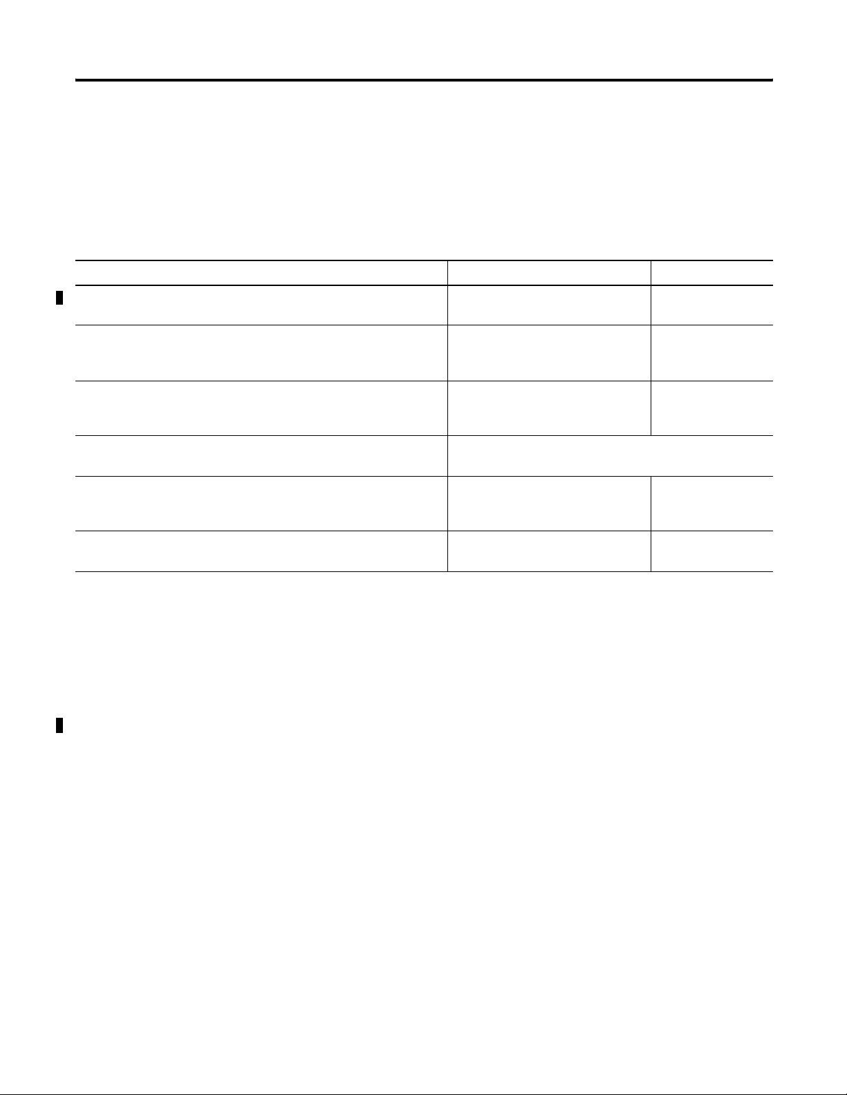
Pico Controllers
7
8
7
8
8
1
Del
2
Alt
3
4
Esc
Del
Alt
Esc
Ok
Ok
5
6
5
3
5
Item Description
1 Incoming Power
2 Inputs
3 Status LED
4 Buttons
5 Socket for memory module or PC interface cable
6 Outputs
7 LCD display
8 Write-On Surface
Publication 1760-UM001D-EN-P - September 2005
Page 15
System Overview 1-3
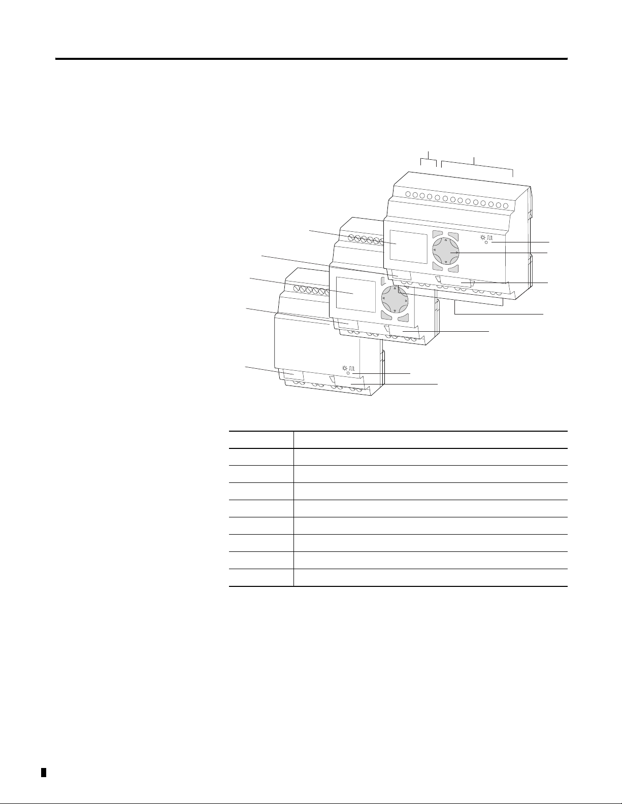
Pico controllers are available for 12V dc, 24V dc, 24V ac and 120/240V
ac operation and come in both 12-I/O and 18-I/O sizes. Pico is
available with and without a real-time clock, and with and without a
display and keypad. See the following table for details.
Catalog Number Inputs Outputs Line Power Real Time
Clock
Display and
Keypad
Analog
1760-L12AWA 8 (100 to 240V ac) 4 (relay) 100 to 240V ac Yes Yes No
1760-L12AWA-NC
1760-L12AWA-ND
(1)
(2)
No Yes
Yes No
1760-L18AWA 12 (100 to 240V ac) 6 (relay) Yes Yes
1760-L18AWA-EX
(3)
1760-L18AWA-EXND
(2)(3)
Yes Yes
Yes No
1760-L12BWB 8 (24V dc) 4 (relay) 24V dc Yes Yes 2 (0 to 10V dc)
1760-L12BWB-NC
1760-L12BWB-ND
(1)
(2)
No Yes
Yes No
1760-L12BBB 4 (MOSFET) Yes Yes 2 (0 to 10V dc)
1760-L12BBB-ND Yes No
1760-L12NWN 8 (24V ac) 4 (relay) 24V ac Yes Yes
1760-L12NWN-ND Yes No
1760-L12DWD 8 (12V dc) 12V dc Yes Yes
1760-L12DWD-ND Yes No
1760-L18BWB-EX
(3)
1760-L18BWB-EXND
1760-L20BBB-EX
(3)
1760-L20BBB-EXND
1760-L18DWD-EX
(3)
1760-L18DWD-EXND
1760-L18NWN-EX
(3)
1760-L18NWN-EXND
12 (24V dc) 6 (relay) 24V dc Yes Yes
(2)(3)
6 (relay) Yes No 2 (0 to 10V dc)
8 (MOSFET) Yes Yes 4 (0 to 10V dc)
(2)(3)
8 (MOSFET) Yes No
12 (12V dc) 6 (relay) 12V dc Yes Yes
(2)(3)
6 (relay) 12V dc Yes No
12 (24V ac) 6 (relay) 24V ac Yes Yes 4 (0 to 10V dc)
(2)(3)
12 (24V ac) 6 (relay) Yes No
(1) NC = no real time clock
(2) ND = no display
(3) EX = suitable for use with expansion modules
Publication 1760-UM001D-EN-P - September 2005
Page 16
1-4 System Overview
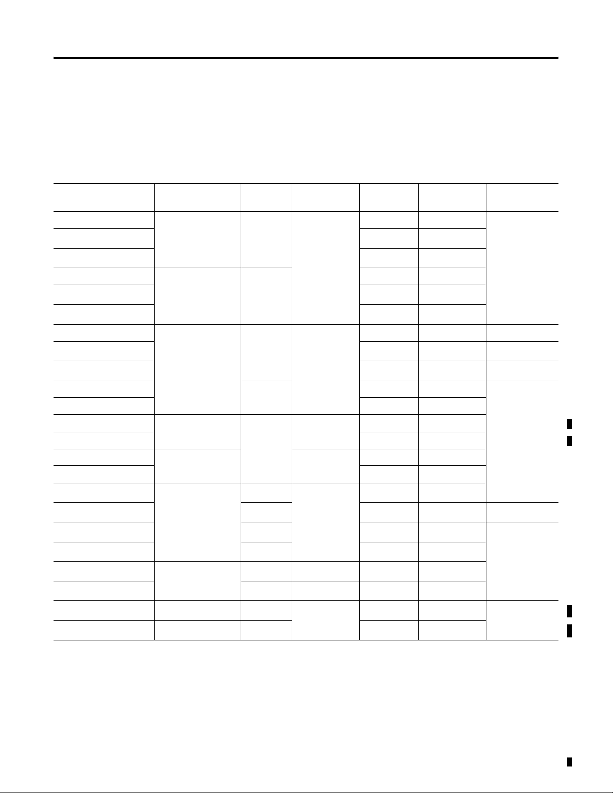
Expansion Modules
3
3
Item Description
1 Incoming Power
2 Inputs
3 Write-On Surface
2
4
1
5
4 Outputs
5 Status LED
Use Pico expansion modules with Pico ’-EX’ models to increase your
I/O capacity. The following modules are available.
Catalog Number Inputs Outputs Line Power
1760-IA12XOW6I 12 (100 to 240V ac) 6 (relay) 100 to 240V ac
1760-IA12XOW4I 12 (100 to 240V ac) 4 (relay) 100 to 240V ac
1760-IB12XOW6I 12 (24V dc) 6 (relay) 24V dc
1760-IB12XOB8 12 (24V dc) 8 (transistor) 24V dc
1760-OW2 - 2 (relay) 24V dc
Publication 1760-UM001D-EN-P - September 2005
Page 17
System Overview 1-5
Expansion modules connect directly to the Pico controller as shown
below.
ATTENTION
(1)
Pico Controller:
1760-L18AWA-EX
1760-L18BWB-EX
1760-L18AWA-EXND
1760-L18BWB-EXND
1760-L18DWD-EX
1760-L20BBB-EX
1760-L20BBB-EXND
Expansion Module Connector
(replacement part 1760-RPLCONN)
Expansion Module:
1760-IA12XOW6I
1760-IB12XOB8
1760-IA12XOW4IF
1760-IB12XOW6I
1760-OW2
(1) Included with expansion module. Catalog
Number is listed as a replacement part.
Electrical isolation is provided between the Pico
controller and the expansion module as follows:
• Basic Isolation: 400V ac (+10%)
• Reinforced Isolation 240V ac (+10%)
(1)
(2)
The controller and expansion units may be
destroyed if the potential between them exceeds the
Basic Isolation value provided. This may cause your
entire system or machine to malfunction.
(1) Basic Insulation - An insulation system which provides a minimal level of protection against electric shock up to
a stated voltage level. Refer to EN 61131-2 for additional information.
(2) Reinforced Insulation - An insulation system comprised of basic and supplemental insulation. This provides
protection against electric shock up to a stated voltage level and is tolerant of a single fault. Refer to EN
61131-2 for additional information.
TIP
The Pico controller and the expansion module can
be of different voltage types.
Publication 1760-UM001D-EN-P - September 2005
Page 18
1-6 System Overview
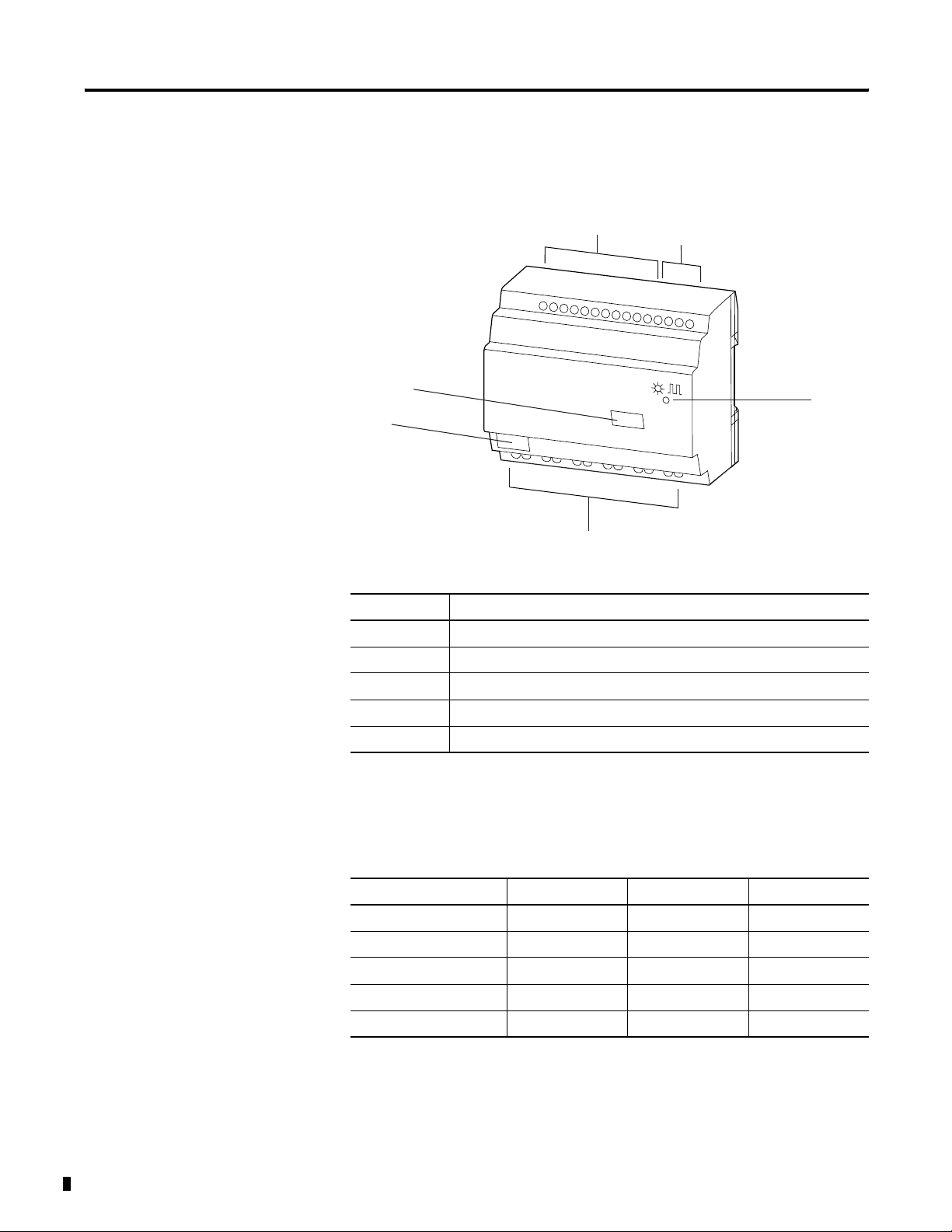
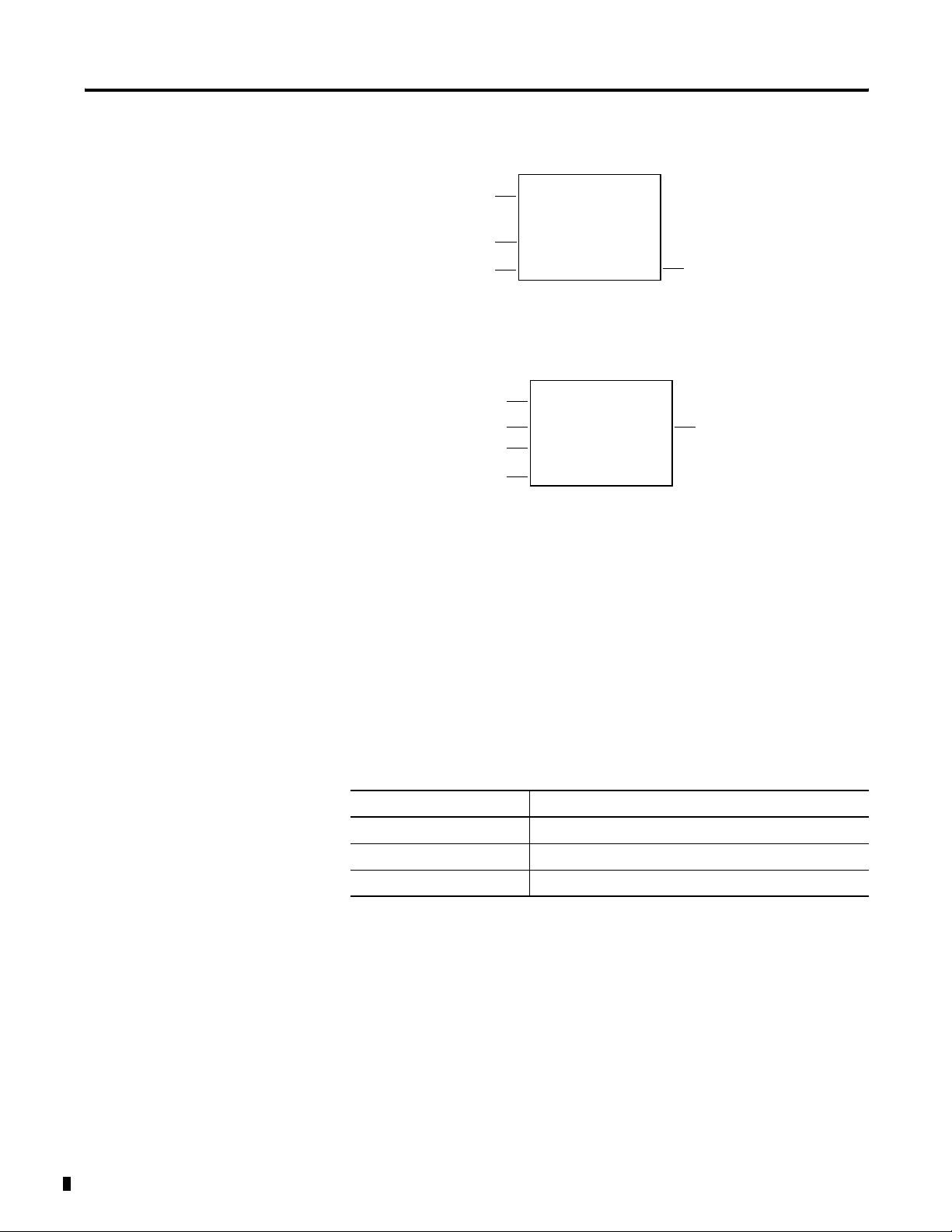
Remote Processor
Remote Processor Features
1
2
1. 24V dc Voltage supply
Operating Principles
2. Interface Terminal (with cover) for connecting cable
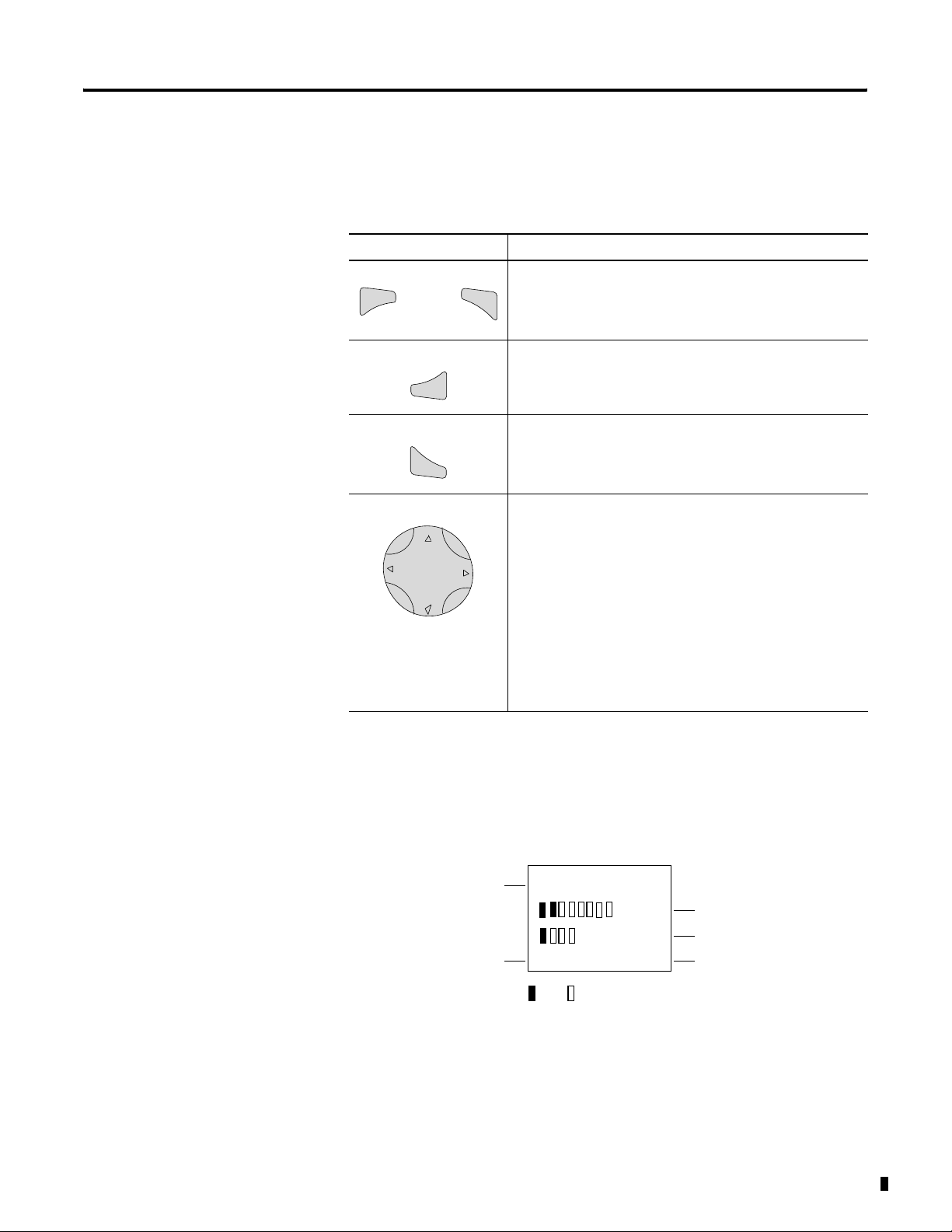
Operating Buttons
Del
Esc
Alt
Button Function
Del Delete object in the circuit diagram
Alt Special functions in the circuit diagram
Cursor
Buttons
Ok
Ok Next menu level, store your entry
Esc Previous menu level, cancel your entry
Move cursor
Select menu item
Choose contact numbers, values, times, etc.
Publication 1760-UM001D-EN-P - September 2005
Page 19
Using Menus to Choose Values
Press To
Show system menu
Del
and
together
Ok
Esc
Alt
• Go to next menu level.
• Select menu item.
• Store your entry.
• Return to last menu level.
• Cancel your entry since the last Ok.
• Change menu item.
• Change value.
• Change position.
System Overview 1-7
Cursor Button Set to P-Button Function (if enabled)
• Left Arrow = Input P1
• Right Arrow = Input P3
• Up Arrow = Input P2
• Down Arrow = Input P4
Selecting the Main and System Menus
1760-L12xxx Status Display
Inputs
Outputs
I12345678
12:50
Q1234 RUN
Off
On
MO
Weekday
Tim e
RUN/STOP Mode
Publication 1760-UM001D-EN-P - September 2005
Page 20
1-8 System Overview
1760-L18xxx Status Display
Inputs
Weekday/Time
Outputs
12...........
MO 02:00
..34.... RUN
Inputs 1 and 2 ON
Outputs 3 and 4 ON
RUN/STOP Mode
1760-L18xxx-EX and 1760-L20xxx Status Display for Expansion Module
Inputs
Expansion
Weekday/Time
Outputs
1..........12
RS
MO 10:42 ST
1.......8
RS = Expansion functioning correctly
AC = AC expansion functioning correctly
DC = DC expansion correctly
AC P-
AC Expansion OK/P Buttons
LED Indicators
Catalog numbers 1760-L12AWA-ND, 1760-L12BWB-ND, 1760-L18xxx,
1760-L20BBB-EXND, 1760-IA12XOW6I, 1760-IB12XOB8,
1760-IA12XOW4I and 1760-IB12XOW6I all feature an LED indicator
on the front that shows the status of the incoming power as well as
Run or Stop status.
Publication 1760-UM001D-EN-P - September 2005
LED Indicator Status Indicates
LED OFF No power
LED continuously lit Power present, Stop mode
LED flashing Power present, Run mode
Page 21
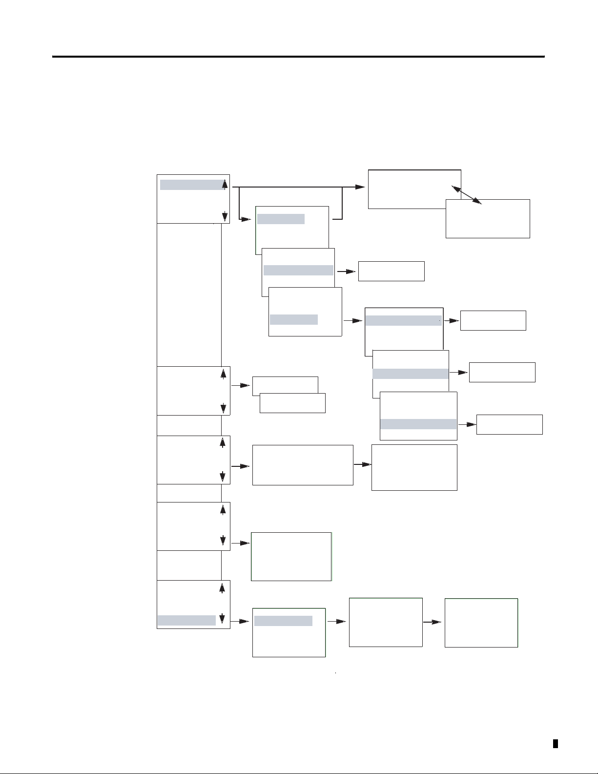
Menu Structure
Main Menu Without Optional Password Protection
STOP: Circuit diagram menu
RUN: Power flow display
System Overview 1-9
PROGRAM...
STOP RUN
PARAMETER
INFO...
SET CLOCK
PROGRAM...
STOP RUN
PARAMETER
INFO...
SET CLOCK
PROGRAM...
STOP RUN
PARAMETER
INFO...
SET CLOCK
PROGRAM...
RUN
PARAMETER
INFO...
SET CLOCK
PROGRAM...
RUN
PARAMETER
INFO...
SET CLOCK
RUN
å
STOP
Circuit Diagram
PROGRAM
Parameter
Display
Parameters
DELETE PROG
CARD ...
PROGRAM
DELETE PROG
DELETE ?
CARD ...
PROGRAM
DELETE PROG
CARD ...
DEVICE->CARD
REPLACE ?
CARD->DEVICE
DELETE CARD
DEVICE->CARD
REPLACE ?
RUN
STOP
CARD->DEVICE
DELETE CARD
DEVICE->CARD
CARD->DEVICE
T1 X
T2
Ü
C1 N
O1
Parameter Display
S
M:S++
DELETE CARD
T1 X
+
+
S1 10.000
S2 +0
T:
Information Display of Device
+S
DELETE ?
DC TC LCD
OS: 1.00.027
CRC: 02752
SET CLOCK
SUMMER TIME
Display for
Setting Clock
HH:MM --:--
DD.MM
YEAR
--.--
----
HH:MM 14:23
DD.MM
YEAR
17.03
2004
Publication 1760-UM001D-EN-P - September 2005
Page 22
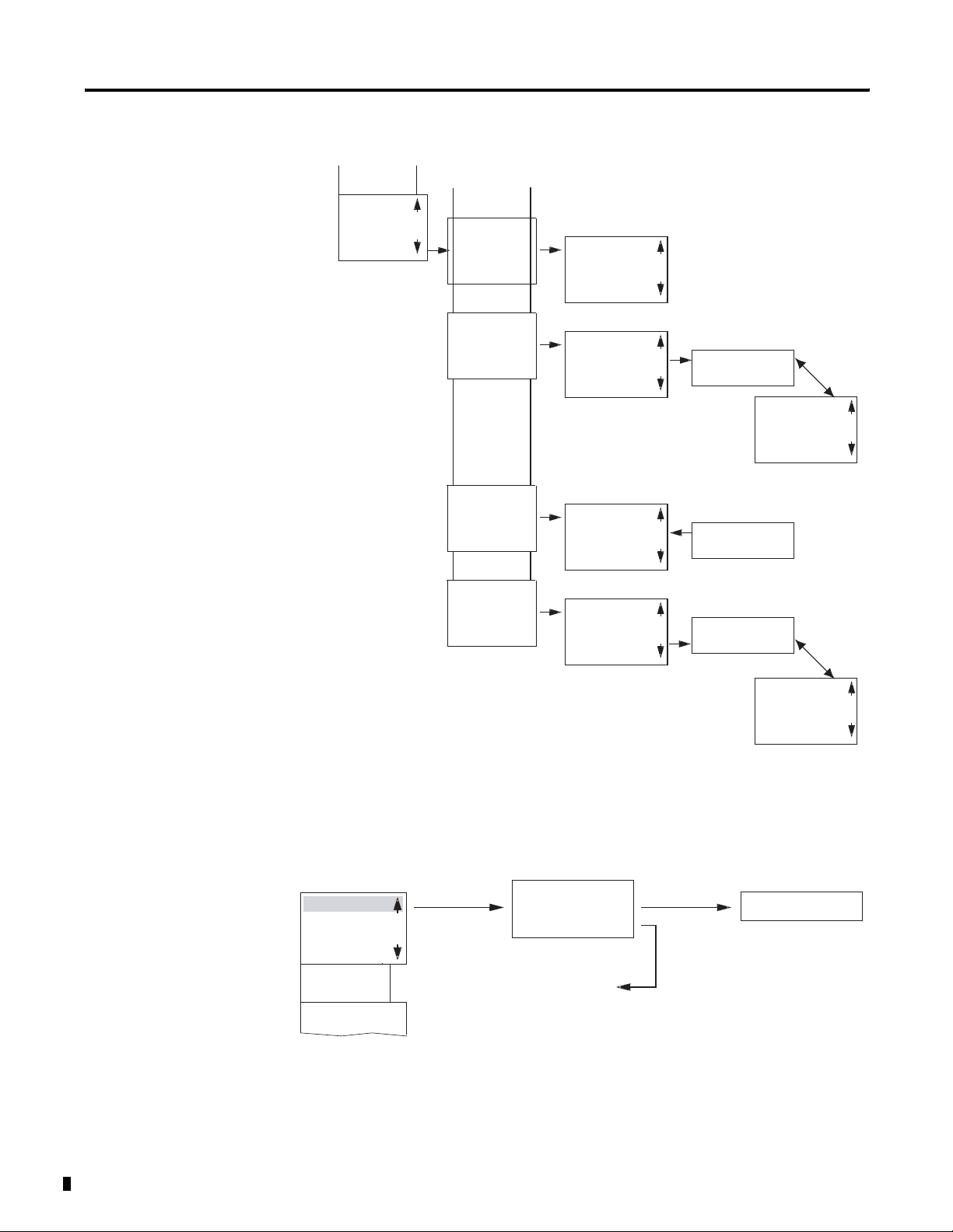
1-10 System Overview
Main Menu Setting Summer Time
PROGRAM...
RUN
PARAMETER
INFO...
SET CLOCK
SET CLOCK
SUMMER TIME
SET CLOCK
SUMMER TIME
SET CLOCK
SUMMER TIME
SET CLOCK
SUMMER TIME
NONE
RULE...
EU
GB
US
NONE
RULE...
EU
GB
US
NONE
RULE...
EU
GB
US
NONE
RULE...
EU
GB
US
å
SUMMER START
SUMMER END
AM -HH:MM --
--
DD.MM:00.00
HH.MM:00:00
DIFF: 0:00
SUMMER START
SUMMER END
SUMMER START
SUMMER END
AM -HH:MM --
--
DD.MM:00.00
HH.MM:00:00
DIFF: 0:00
Main Menu
PASSWORD...
RUN
PARAMETER
INFO...
SET CLOCK
PASSWORD...
RUN
Publication 1760-UM001D-EN-P - September 2005
Main Menu with Password Protection
Password Entry
Unlock
Password
Status Display
Correct Entry
Four Wrong
Entries
DELETE ALL
Page 23
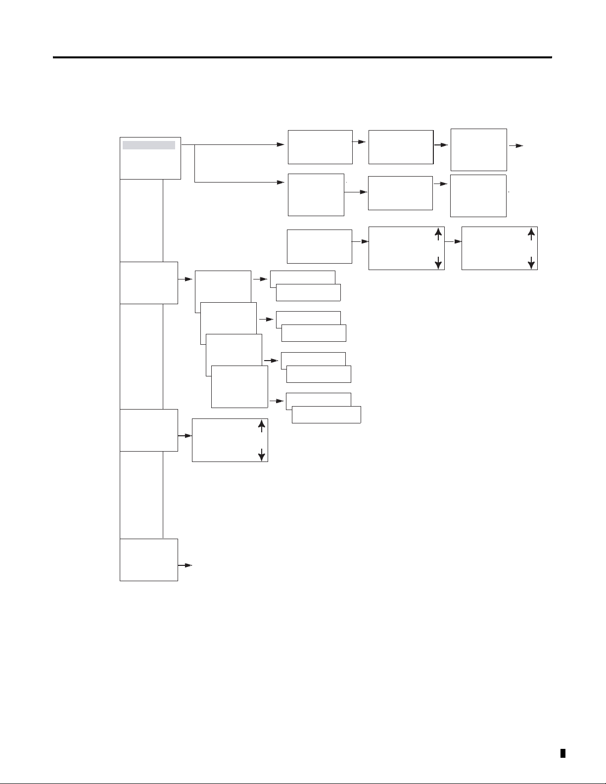
System Menu
System Overview 1-11
System
sECURITY...
SYSTEM...
LANGUAGE ...
CONFIGURATOR
SECURITY...
SYSTEM...
LANGUAGE...
CONFIGURATOR
SECURITY...
SYSTEM...
LANGUAGE...
CONFIGURATOR
SECURITY...
SYSTEM...
LANGUAGE...
CONFIGURATOR
Set Password
Change Password
DEBOUNCE OFF
P ON
STOP MODE
DEBOUNCE OFF
P ON
STOP MODE
DEBOUNCE OFF
P ON
STOP MODE
DEBOUNCE OFF
P ON
STOP MODE
RETENTION ON
ENGLISH
DEUTSCH
FRANCAIS
ESPANOL
ITALIANO
PORTUGUES
NEDERLANDS
SVENSKA
POLSKI
TURKCE
CESKY
MAGYAR
Password Entry
Password
RANGE...
ACTIVATE PW
CHANGE PW
Password
RANGE...
DEBOUNCE OFF
DEBOUNCE ON
P ON
P OFF
MODE: STOP
MODE: RUN
(2)
RETENTION ON
RETENTION OFF
ENTER PASSW:
XXXX
ENTER PASSW:
XXXX
PROGRAM å
PARAMETER
CLOCK
OPRTNG MODE
INTERFACE
DELETE FUNCT
(2)
(2)
(1) Only for Pico 1760-L18xxx
(2) Only for Pico 1760-L12BWB-xx,
-L12DWD and -L18xxx.
CHANGE PW
ACTIVATE PW
CHANGE PW
ACTIVATE PW
PROGRAM å
PARAMETER å
CLOCK å
OPRTNG MODE å
INTERFACE å
DELETE FUNCT å
Publication 1760-UM001D-EN-P - September 2005
Page 24
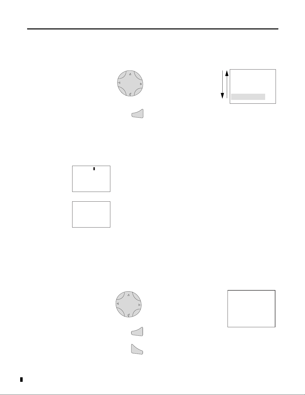
1-12 System Overview
Selecting or Toggling Between Menu Items
HH:MM 14:23
DD.MM
YEAR
HH:MM 14:23
DD.MM
YEAR
17.03
2004
17.03
2004
Cursor up or down
Select or Toggle
Ok
PROGRAM ...
RUN
PARAMETER
INFO
Highlighted
choice flashes
Cursor Display
There are two different cursor types: flashing block and flashing
cursor.
Full block navigation is shown as a flashing block:
• Move cursor with the left/right arrows
• In circuit diagram also with up/down arrows
Parameter change cursor flashes the selected parameter:
• Change position with left/right arrows
• Change values with up/down arrows
Publication 1760-UM001D-EN-P - September 2005
Flashing values/menus are highlighted in grey in this manual.
Setting Values
Change value = up/down arrows
Move cursor between parameters = left/right
arrows
Stores Entries
Ok
Retain previous value
Esc
HH:MM 14:23
DD.MM
YEAR
Left/right arrow moves the
cursor between the day and
time digits.
Up/down arrow changes the
value of the parameter.
Up arrow = increment
Down arrow = decrement
17.03
2004
Page 25
Installation
Pico is installed in the following order:
• connect devices together, if necessary
• Mount
• Use surge suppressors
• Wire the inputs
• Wire the outputs
• Connect incoming power
Chapter
2
Prevent Electrical Shock
ATTENTION
Follow these guidelines when you handle the
controller:
• Remove power before working on any of the
wiring to Pico.
• Touch a grounded object to discharge static
potential.
• Wear an approved wrist-strap grounding device.
• If available, use a static-safe work station.
1 Publication 1760-UM001D-EN-P - September 2005
Page 26

2-2 Installation
European Communities (EC) Directive Compliance
If this product has the CE mark it is approved for installation within
the European Union and EEA regions. It has been designed and tested
to meet the following directives.
EMC Directive
This product is tested to meet the Council Directive 89/336/EC
Electromagnetic Compatibility (EMC) by applying the following
standards, in whole or in part, documented in a technical construction
file:
• EN 50081-1 EMC — Generic Emission Standard, Part 1 —
Residential, Commercial, and Light Industry
• EN 50082-2 EMC — Generic Immunity Standard, Part 2 —
Industrial Environment
This product is intended for use in an industrial environment.
Low Voltage Directive
This product is tested to meet Council Directive 73/23/EEC Low
Voltage, by applying the safety requirements of EN 50178 Electric
Equipment for Power Installations Equipment Requirements and Tests.
For specific information required by EN 50178, see the appropriate
sections in this publication, as well as the Allen-Bradley publication
Industrial Automation Wiring and Grounding Guidelines For Noise
Immunity, publication 1770-4.1.
This equipment is classified as open equipment and must be mounted
in an enclosure during operation to provide safety protection.
Publication 1760-UM001D-EN-P - September 2005
Page 27

Installation 2-3
Connect the Expansion Module
Connect the expansion module to the controller using the connector
as shown below:
1
2
See Expansion Modules on page 1-4 for information on using the
modules with your Pico controller.
Mount the Pico Controller
Install Pico in an enclosure, switch cabinet, or distribution board so
that the power feed and terminal connections cannot be touched
accidentally during operation.
Clip Pico onto a DIN rail or install directly onto a panel using the
mounting feet. Pico can be mounted either vertically or horizontally.
TIP
When using a Pico expansion module, connect the
expansion module and Pico controller together
before mounting. See Connect the Expansion
Module.
Publication 1760-UM001D-EN-P - September 2005
Page 28
2-4 Installation
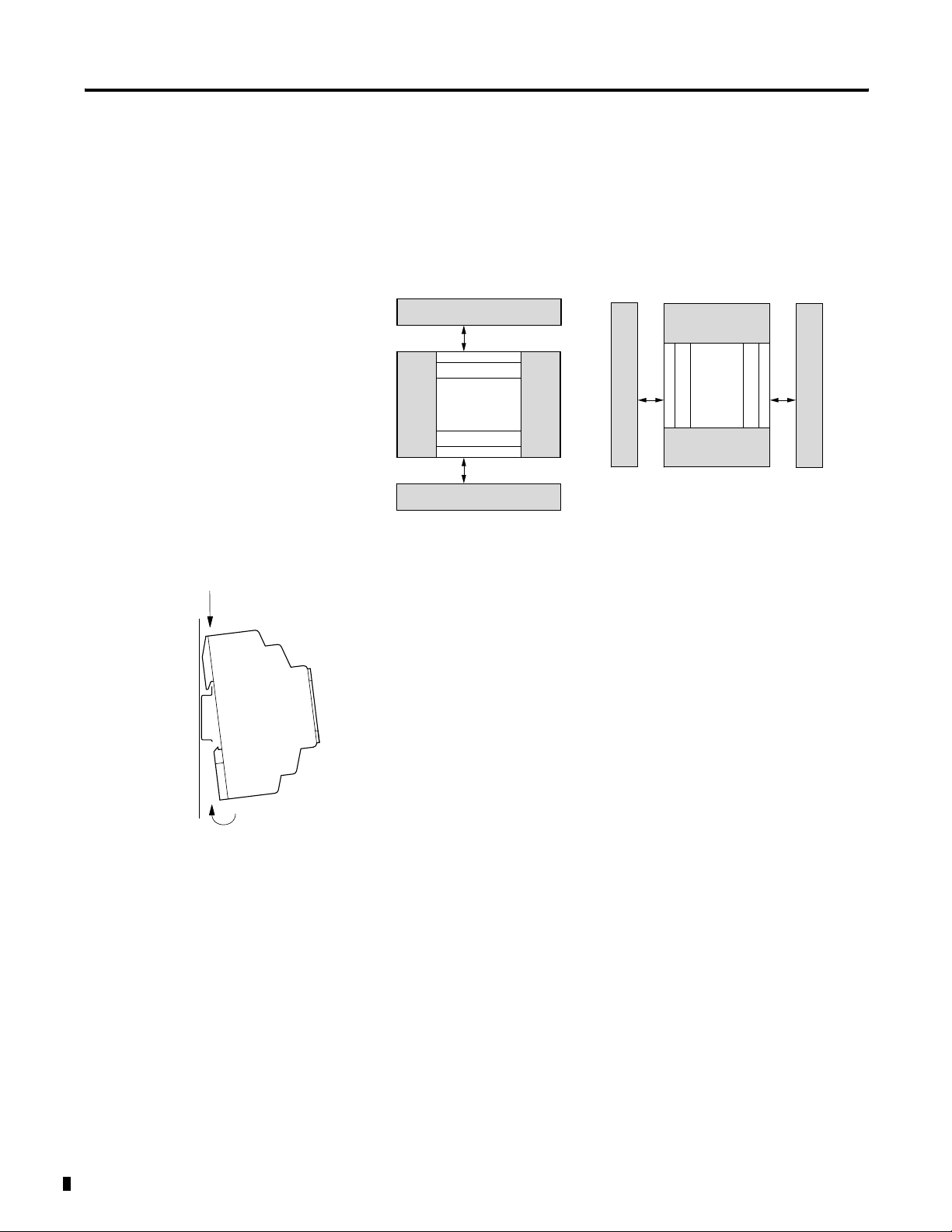
Minimum Spacing
Maintain spacing from enclosure walls, wireways, adjacent equipment,
etc. Allow 3 cm (1.18 in.) of space on all sides for adequate
ventilation, as shown:
3 cm (1.18 in.)
3 cm (1.18 in.)
3 cm (1.18 in.)
3 cm (1.18 in.)
DIN Rail Mount
1. Mount your DIN rail. Make sure that the placement of the Pico
unit on the DIN rail meets the recommended spacing
requirements.
2. Hook the top slot over the DIN rail.
3. While pressing the Pico unit down against the top of the rail,
snap the bottom of the unit into position. Ensure DIN latches are
in the up (secured) position.
Pico can be mounted vertically on a DIN rail in the same manner.
Publication 1760-UM001D-EN-P - September 2005
Page 29
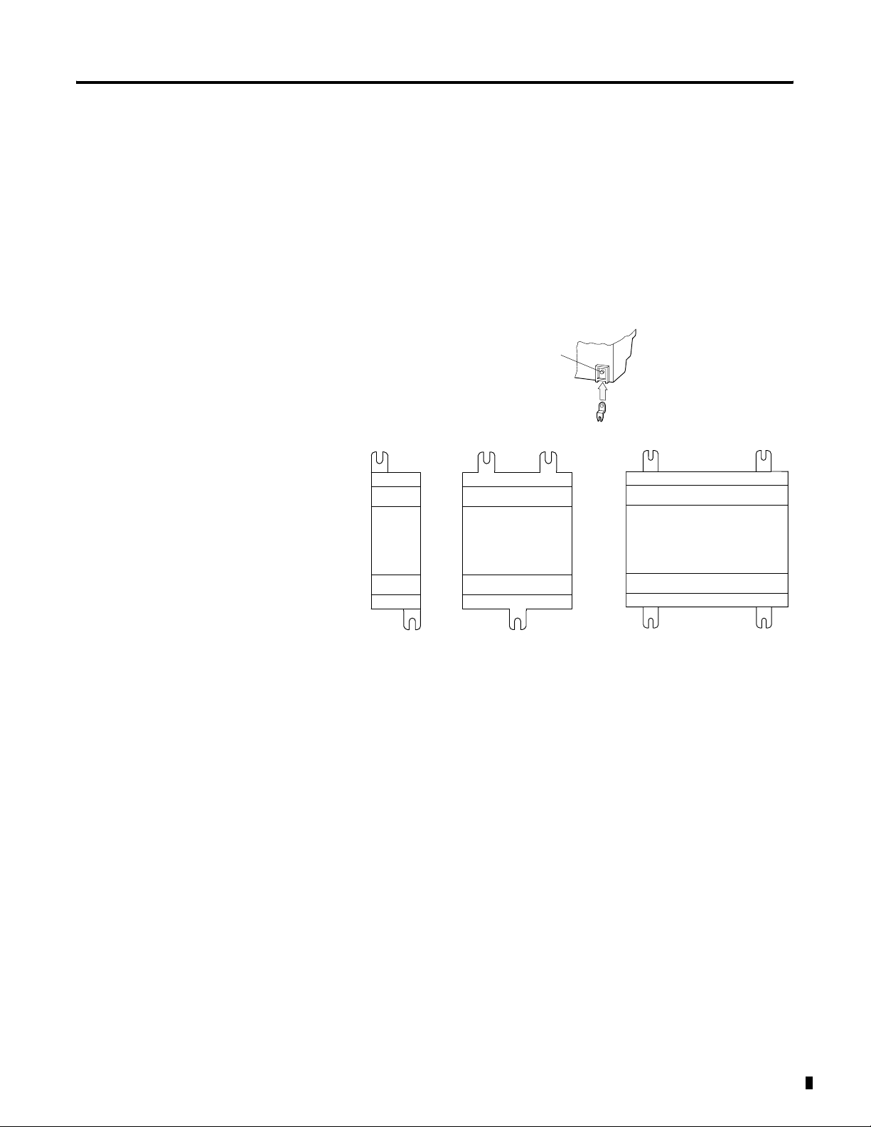
Install on a Mounting Plate
To install the unit using mounting screws:
1. Snap the mounting feet in place.
2. Drill holes at the mounting feet positions, shown below.
3. Mount the controller.
Click
Installation 2-5
1760-L18xxx, 1760-L20xxx and
Expansion Modules
1760-OW2
1760-L12xxx
For mounting dimensions, see Dimensions on page A-14.
Publication 1760-UM001D-EN-P - September 2005
Page 30
2-6 Installation
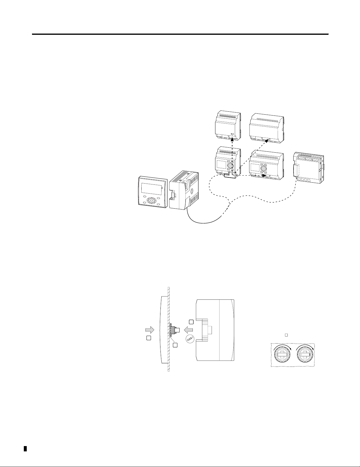
Install the Remote Processor
The remote processor is used for terminal mode operation of Pico
controllers and I/O modules. The remote processor is used with either
a Display or Display/Keypad Unit.
Remote Processor Terminal Operation
1760-L18...
1760-L20...
LED
LA
T
E
S
C
O
K
1760-RM-GFX
1760-LDF
...
1760-GFX
Display Unit
Front View
1760-RM
1760-L12...
D
E
L
LA
T
E
S
C
O
K
1760-RM-Pico
Flush Mount
Flush Mount the Display and Remote Processor
3
2
1
2
1. Insert the display unit through the mounting holes on the panel.
2. Attach the fixing rings.
3. Attach the processor unit.
M = 1.2 – 2 Nm
10.6 - 17.7 lb-in
Publication 1760-UM001D-EN-P - September 2005
Page 31

Removal Procedure
Remove the Remote Processor
3
2
1
1760 -RM
1. Insert the screwdriver into the mounting slide.
2. Push screwdriver to the right to open the slide.
Installation 2-7
3. Remove the processor unit from the display unit.
4. Loosen the fixing rings.
5. Remove the display unit from the panel.
Make Connections
Connect the Power Supply
Remote Processor Power Supply Connection
1760-RM…
L01+ L02+
L01–
> 1 A
Ue = 24 V dc
(20.4 – 28.8 V H dc)
Ie = 150 mA
0.6 x 3.5 x 100
0V24V
Publication 1760-UM001D-EN-P - September 2005
Page 32

2-8 Installation
Connect the Serial Cable
4
1
Wire Terminals
1760-RM cable
2
X5
X4
X3
X2
X1
3
Cable Wire Color Code
X5
green
X4 white
X3 yellow
X2 brown
X1 gray
1. Remove the interface cover.
2. Using a screwdriver, push on the terminal latch.
3. Insert each wire into its designated terminal on the interface
connector.
4. Replace the interface cover.
Plug the other end of the cable into the Pico controller or I/O module.
Required Tools
Publication 1760-UM001D-EN-P - September 2005
Slot-head screwdriver (width: 3.5 mm, torque: 0.57 to 0.79 Nm [5 to 7
in-lb])
Page 33

Wire Size
• Solid
AWG 22 to AWG 12
• Stranded
AWG 22 to AWG 12
Installation 2-9
Connect the Incoming Power
For incoming power technical specifications, refer to Appendix A.
ATTENTION
ELECTRICAL SHOCK HAZARD
The memory module and PC-cable socket are at the
potential of L2. There is a danger of electric shock if
L2 is not grounded. Do not make contact with
electrical components under the socket cover.
TIP
A brief current surge is produced when powering on
the unit for the first time. Do not switch the unit
using reed contacts, since these may burn or melt.
1760-L12AWA, -L12AWA-NC, -L12AWA-ND, -L18AWA,
L1
L2
F1
L1 L2 I2 I3 I4 I5 I6 I7 I8I1
100 - 240V ac
50/60Hz
Inputs x 100 - 240V ac
Publication 1760-UM001D-EN-P - September 2005
Page 34

2-10 Installation
1760-IA12XOW6I Expansion Module
L1
L2
F1
NCNC R2 R3 R4 R5 R6 R7 R8R1 R9 R10 R11 R12 L1
Inputs x 100 to 240V ac
1760-L12BWB, -L12BWB-NC, -L12BWB-ND, -L18BWB-EX
+24V
0V
F1
+24 V COM I2 I3 I4 I5 I6 I7 I8I1
24V dc
Inputs x 24V dc (I7,I8 0 to 10V)
L2
100 to 240V ac
50/60Hz
Publication 1760-UM001D-EN-P - September 2005
Page 35

1760-IB12XOB8 Expansion Module
+24V dc
0V dc
Installation 2-11
F1
NCNC R2 R3 R4 R5 R6 R7 R8R1 R9 R10 R11 R12 +24V
1760-L12DWD
+12V dc
0V
F1
+12 V COM I2 I3 I4 I5 I6 I7 I8I1
12V dc
Inputs x 24V dc
Inputs x 12V dc
COM
24V dc
The dc controllers are protected against polarity reversal. To ensure
that the unit works correctly, ensure that the polarity of each terminal
is correct.
Wiring Protection
Both AC and DC versions require wiring protection (F1) rated for at
least 1 A (slow).
When the unit is powered on for the first time, the power supply
circuit draws a larger surge current than usual. Use an appropriate
device for switching on the incoming power and do not use any reed
relay contacts or proximity switches.
Publication 1760-UM001D-EN-P - September 2005
Page 36

2-12 Installation
Use Surge Suppressors
Inductive load devices, such as motor starters and solenoids, require
the use of some type of surge suppression to protect and extend the
operating life of the controller’s output contacts. Switching inductive
loads without surge suppression can SIGNIFICANTLY reduce the life
expectancy of relay contacts. By adding a suppression device directly
across the coil of an inductive device, you prolong the life of the
output or relay contacts. You also reduce the effects of voltage
transients and electrical noise from radiating into adjacent systems.
The following diagram shows an output with a suppression device.
We recommend that you locate the suppression device as close as
possible to the load device.
ac or dc
Outputs
+dc or L1
VAC/DC
Out 0
Out 1
Out 2
Out 3
Out 4
Out 5
Out 6
Out 7
COM
Suppression
Device
dc COM or L2
If the outputs are dc, we recommend that you use an 1N4004 diode
for surge suppression, as shown below.
+24V dc
VAC/D
Out 0
Out 1
Relay or Solid
State dc Outputs
Out 2
Out 3
Out 4
Out 5
Out 6
Out 7
COM
IN4004 Diode
24V dc common
Suitable surge suppression methods for inductive ac load devices
include a varistor, an RC network, or an Allen-Bradley surge
suppressor, all shown below. These components must be
appropriately rated to suppress the switching transient characteristic of
the particular inductive device. See the table on page 2-14 for
recommended suppressors.
Publication 1760-UM001D-EN-P - September 2005
Page 37

Surge Suppression for Inductive ac Load Devices
Installation 2-13
Output Device
Varistor RC Network Surge
Output Device
For inductive dc load devices, a diode is suitable. A 1N4004 diode is
acceptable for most applications. A surge suppressor can also be used.
See the table on page 2-14 for recommended suppressors.
As shown in the illustration below, these surge suppression circuits
connect directly across the load device.
Surge Suppression for Inductive dc Load Devices
_
Output Device
+
Output Device
Suppressor
Diode
(A surge suppressor can also be used.)
Publication 1760-UM001D-EN-P - September 2005
Page 38

2-14 Installation
Recommended Surge Suppressors
Use the Allen-Bradley surge suppressors shown in the following table
for use with relays, contactors, and starters.
Suppressor Device Coil Voltage Catalog Number
Bulletin 509 Motor Starter
Bulletin 509 Motor Starter
Bulletin 100 Contactor
Bulletin 100 Contactor
120V ac
240V ac
120V ac
240V ac
599-K04
599-KA04
199-FSMA1
199-FSMA2
Bulletin 709 Motor Starter 120V ac 1401-N10
Bulletin 700 Type R, RM Relays ac coil None Required
Bulletin 700 Type R Relay
Bulletin 700 Type RM Relay
Bulletin 700 Type R Relay
Bulletin 700 Type RM Relay
Bulletin 700 Type R Relay
Bulletin 700 Type RM Relay
Bulletin 700 Type R Relay
Bulletin 700 Type RM Relay
Bulletin 700 Type R Relay
Bulletin 700 Type RM Relay
12V dc
12V dc
24V dc
24V dc
48V dc
48V dc
115-125V dc
115-125V dc
230-250V dc
230-250V dc
700-N22
700-N28
700-N10
700-N13
700-N16
700-N17
700-N11
700-N14
700-N12
700-N15
Bulletin 700 Type N, P, or PK Relay 150V max, ac or DC 700-N24
Miscellaneous electromagnetic
150V max, ac or DC 700-N24
devices limited to 35 sealed VA
Connect the Inputs
Publication 1760-UM001D-EN-P - September 2005
Pico inputs switch electronically. Once you have connected a device
via an input terminal, you can reuse it as a relay contact in your
program as often as you like.
L1
+24 V
S1
L2
com
I1
I1
I1
Connect devices such as buttons or switches to Pico input terminals.
Page 39

Connecting AC Inputs
Installation 2-15
ATTENTION
For Pico controllers with ac inputs, connect the
inputs to the same phase as the power feed L1, in
accordance with VDE, IEC, UL and CSA safety
regulations. Otherwise, Pico may not detect the
switching level or, it may be damaged by excess
voltage.
Input Specification
Input Signal
Voltage Range
Input Current I1 to I6, I9 to I12, R1 to R12: 0.25 mA at 120V ac, 0.5 mA at 240V ac
Example Using 1760-L12AWA
L1
L2
OFF signal: 0 to 40V ac
ON signal: 79V to 264V ac
I7 and I8: 4 mA at 120V ac, 6 mA at 240V ac,
F1
L1 L2 I2 I3 I4 I5 I6 I7 I8I1
100 to 240V ac
50/60Hz
Example Using 1760-IA12XOW6I
F1
L1
L2
NCNC R2 R3 R4 R5 R6 R7 R8R1 R9 R10 R11 R12 L1
Inputs x 100 to 240V ac
Inputs x 120/240V ac
Publication 1760-UM001D-EN-P - September 2005
120/240V ac
L2
50/60Hz
Page 40

2-16 Installation
Wire Lengths
Severe electromagnetic interference to wires can cause inputs to signal
1 without the proper signal being applied. Observe the following
maximum cable lengths:
• I1 to I6, I9 to I12, R1 to R12: 40m (130 ft) without additional
circuits
• I7 and I8: 100m (330 ft) without additional circuits
ATTENTION
Do not use reed relay contacts on I7 or I8. These
may burn or melt due to the high current of I7 and
I8.
Two-wire proximity sensors have a residual off-state leakage current.
If this residual current is too high, the input may indicate the input is
ON when the device is actually off.
Use inputs I7 and I8 for these types of input devices. If more inputs
are required, use a bleeder resistor or bleeder capacitor for inputs I1
through I6, and I9 through I12.
Increase the Input Current
Use the following input circuit for electrical noise immunity and when
using two-wire proximity switches:
L1
L2
Publication 1760-UM001D-EN-P - September 2005
1A
30K Ω, 5W resistor; or
100 nF, 275V ac capacitor
L1 L2 I2 I3 I4 I5 I6 I7 I8I1
100 to 240V ac
50/60Hz
Inputs x 100 to 240V ac
When using a 100 nF capacitor, the drop-off time of the input
increases by 66.6 ms at 60 Hz (80 ms at 50 Hz). Also, a capacitor
increases the amount of current seen by the input device. Do not use
a bleeder capacitor in conjunction with reed switches.
Page 41

Installation 2-17
To limit the current to 400 mA, connect a 1K Ω resistor in series
upstream from the circuit as shown.
.
L1
L2
1A
1K Ω
0.25W
resistor
L1 L2 I2 I3 I4 I5 I6 I7 I8I1
100 to 240V ac
50/60Hz
100 nF, 275V ac capacitor
Inputs x 100 to 240V ac
Connect 24 V dc Inputs
Use input terminals I1 to I8 (or I12 for 18-point Pico) to connect
push-buttons, switches, or 3- or 4-wire proximity switches. Given the
high off-state leakage current, do not use 2-wire proximity switches.
Input Specification
Input Signal Voltage Range OFF signal: 0 to 5V dc
ON signal: 15V to 28.8V dc
Input Current I1 to I6, I9 to I12, R1 to R12: 3.3 mA at 24V dc
I7 and I8: 2.2 mA at 24V dc
Example Using 1760-L12BWB-xx
+24V
0V
1A
+24 V COM I2 I3 I4 I5 I6 I7 I8I1
24V dc
Inputs x 24V dc (I7,I8 0 to 10V)
Publication 1760-UM001D-EN-P - September 2005
Page 42

2-18 Installation
Example Using 1760-IB12XOB8
+24V dc
F1
0V
NCNC R2 R3 R4 R5 R6 R7 R8R1 R9 R10 R11 R12 +24V
Inputs x 24V dc
COM
24V dc
Connect 12 V dc Inputs
Use input terminals I1 to I8 to connect push-buttons, switches, or 3 or
4-wire proximity switches. Given the high off-state leakage current, do
not use 2-wire proximity switches.
Input Specification
Input Signal Voltage Range OFF signal: 0 to 4V dc
ON signal: 8V to 15.6V dc
Input Current I1 to I6, I9 and I10: 3.3 mA at 12V dc
I7 and I8, I11 and I12: 1.1 mA at 12V dc
Example Using 1760-L12DWD
+12V dc
0V
1A
+12 V COM I2 I3 I4 I5 I6 I7 I8I1
12V dc
Inputs x 12V dc
Publication 1760-UM001D-EN-P - September 2005
Page 43

Installation 2-19
Connect Analog Inputs (1760-LxxBWB-xx or 1760-LxxDWD only)
Inputs I7 and I8, and if present I11 and I12, can also be used to
connect analog devices ranging from 0 to 10V dc.
ATTENTION
Analog signals are more sensitive to interference than
digital signals. Consequently, more care must be
taken when routing and connecting the signal lines.
Route the analog wiring:
• away from power lines, load lines and other
sources of electrical noise such as hard-contact
switches, relays, and AC motor drives
• away from sources of radiated heat
Incorrect switching states may occur if the analog
wiring is not installed correctly.
Use shielded, twisted-pair cables to prevent interference with the
analog signals. For short cable lengths, ground the shield at both ends
with a large contact area. If the cable length exceeds 30m (98.4 ft),
grounding at both ends can result in ground loops between the two
grounding points and thus to the interference of analog signals. In this
case, only ground the cable at one end. Do not route signal lines
parallel to power cables.
Connect inductive loads to be switched via Pico outputs to a separate
power feed, or use a suppressor circuit for motors and valves. If loads
such as motors, solenoid valves or contactors are operated via the
same power feed, switching may result in interference on the analog
input signals.
Publication 1760-UM001D-EN-P - September 2005
Page 44

2-20 Installation
The following four circuits illustrate application examples for analog
value processing.
Ensure that the reference potential is connected. Connect the 0V of
the power supply unit for the different setpoint potentiometers and
sensors to the 0V of the power feed.
Setpoint Potentiometers
V dc
0V
F1
V dc COM I2 I3 I4 I5 I6 I7 I8I1
V dc
V dc = 12Vdc for 1760-L12DWD
V dc = 24V dc for 1760-LxxBWB-xx
Inputs x V dc (I7,I8 0 to 10V)
~
0V
+12V
Use a potentiometer with a resistance of less than or equal to 1K Ω,
e.g. 1K Ω, 0.25W.
Light Intensity Sensors
V dc
0V
12V
F1
0 to 10V
0V
~
0V
+12V
Publication 1760-UM001D-EN-P - September 2005
V dc COM I2 I3 I4 I5 I6 I7 I8I1
V dc
V dc = 12Vdc for 1760-L12DWD
V dc = 24V dc for 1760-LxxBWB-xx
Inputs x V dc (I7,I8 0 to 10V)
Page 45

Temperature Sensors
Installation 2-21
V dc
0V
V dc = 12Vdc for 1760-L12DWD
V dc = 24V dc for 1760-LxxBWB-xx
20 mA Sensors
V dc
0V
F1
V dc COM I2 I3 I4 I5 I6 I7 I8I1
V dc
1A
+V dc
-0V
Out
0 to 10V
Inputs x V dc (I7,I8 0 to 10V)
4 to 20 mA
(12V dc or 24V dc)
-35 to +55˚C
(-31 to +131˚F)
500Ω
V dc COM I2 I3 I4 I5 I6 I7 I8I1
V dc
V dc = 12Vdc for 1760-L12DWD
V dc = 24V dc for 1760-LxxBWB-xx
Inputs x V dc (I7,I8 0 to 10V)
Connect 4 to 20 mA (0 to 20 mA) sensors using an external 500Ω
resistor, as shown above. The resultant impedance to the sensor is
approximately 478Ω.
The following values result (Based on V = R x I = 478Ω x 10 mA =
4.8V dc):
• 4 mA = 1.9V dc
• 10 mA = 4.8V dc
• 20 mA = 9.5V dc
Publication 1760-UM001D-EN-P - September 2005
Page 46

2-22 Installation
Connect Outputs
The Q output terminals function as isolated contacts, as shown below.
Q1
Q1
12
Q1
Outputs are controlled via the corresponding output relays:
• Q1 to Q4
• Q1 to Q8
• S1 to S6
• S1 to S8
You can use the signal states of the output relays as make or break
contacts in the Pico program to provide additional logic conditions.
The relay or transistor outputs are used to switch loads such as
fluorescent tubes, filament bulbs, contactors, relays or motors. Check
the technical thresholds and output data before installing such devices
(see Relay Outputs on page A-10).
Connect Relay Outputs
1760-L12AWA-xx, 1760-L12BWB-xx and 1760-L12DWD
.
10 000 000
0 V , N
< 8 A / B 16
L1, L2, L3 (120/240V)
+ 24 V
1
2
Q1
1
2
2
1
Q3 Q4
Q2
2
1
R
24 V 8 A
120 V 8 A
240 V 8 A
1000 W
10 x 58 W
L
2 A
2 A
2 A
25.000
Publication 1760-UM001D-EN-P - September 2005
Page 47

1760-L18AWA-xx and 1760-L18BWB-EX
Installation 2-23
10 000 000
0 V , N
< 8 A / B 16
L1, L2, L3 (120/240 V)
+ 24 V
1760-IA12XOW6I
10 000 000
0 V , N
< 8 A / B 16
L1, L2, L3 (120/240 V)
+ 24 V
12 2 2 2 2 2
S1
S2
12 2 2 2 2 2
S1
S2
1
1
1
1
1
1
S6S5S4S3
1
1
S6S5S4S3
1
1
R
24 V
120 V 8 A
240 V 8 A
1000 W
10 x 58 W
R
24 V
120 V 8 A
240 V 8 A
1000 W
10 x 58 W
8A
8A
2A
2A
2A
2A
2A
2A
25.000
25.000
1760-OW2
Unlike inputs, you can connect different phases to the outputs.
.
ATTENTION
Do not exceed the maximum voltage of 250V ac on a
relay contact.
If the voltage exceeds this threshold, arcing may
occur at the contact, resulting in damage to the
device or to a connected load.
Publication 1760-UM001D-EN-P - September 2005
Page 48

2-24 Installation
Connect Transistor Outputs
1760-Ixxx
1760-Ixxx
0 V Q1 Q2 Q3 Q4
+24 V
Q
F 10 A
0 V H
f 2.5 A
+ 24 V H
20.4 – 28.8 V H
+24 V 0 V Q1 Q2 Q3Q4Q5Q6Q7
Q
24 V
Q
Q
5 W/24 V
0.5 A
R
L
0.5 A
Q8
1760-IB12XOB8
F 10 A
0 V H
f 2.5 A
0V
24V 0.5A 0.5A
+ 24 V H
(20.4 – 28.8 V H)
R
24 V H
S1 S2 S3 S4 S5 S6 S7 S8
5W/24V
0.5 A
R
2.5A
≤
0.5 A
5 W/24 V
+24V dc
+ 24V dc
(20.4-28.8V dc )
COM
10A
Publication 1760-UM001D-EN-P - September 2005
Page 49

Installation 2-25
Parallel Connection
Up to four outputs can be connected in parallel in order to increase
the load current. The output current will increase to a maximum of
2A.
ATTENTION
Outputs may only be connected in parallel within a
group (S1 to S4) or (S5 to S8) such as (S1 and S3) or
(S5, S7 and S8). Outputs connected in parallel must
be switched ON and OFF at the same time.
Switch Inductive Loads
ATTENTION
If inductive loads are not suppressed, only one inductive load should
be switched off at any one time to prevent the output transistors from
overheating. If, in the event of an emergency stop, the +24V dc power
supply is to be switched off by means of a contact, and this would
mean switching off more than one controlled output with an inductive
load, then you must provide suppressor circuits for these loads. See
the following diagrams.
Observe the following when switching off inductive
loads:
Suppressed inductive loads cause less interference in
the entire electrical system. For optimum
suppression, the suppressor circuits are best
connected directly to the inductive load. See Use
Surge Suppressors on page 2-12.
+24V
0V
S
Ue max. < Uz < 33V
S
0 V
Publication 1760-UM001D-EN-P - September 2005
Page 50

2-26 Installation
Short Circuit and Overload Behavior
If a short circuit or overload occurs on a transistor output, this output
will switch off. The output will switch on up to maximum temperature
after the cooling time has elapsed. This time depends on the ambient
temperature and the current involved. If the fault condition persists,
the output will continue to switch off and on until the fault is
corrected or until the power supply is switched off.
For information on using the 1760-IB12XOB8 expansion module to
monitor outputs for a fault, see Monitor for Short Circuit or Overload
on page 9-4.
Publication 1760-UM001D-EN-P - September 2005
Page 51

Commission the Pico
Chapter
3
Power On Unit
Before powering up Pico, check that you have connected the power
supply terminals and inputs correctly.
12V dc version:
• +12V terminal: +12V dc voltage
• COM terminal: 0V voltage
• terminals I1 to I8: actuation via +12V dc
24V dc version:
• +24V terminal: +24V dc voltage
• COM terminal: 0V voltage
• terminals I1 to I12, R1 to R12: actuation via +24V dc
100 to 240V ac version:
• terminal L1: phase conductor L1
• terminal L2: neutral conductor L2 (grounded)
• terminals I1 to I12, R1 to R12: actuation via phase conductor L1
ATTENTION
1 Publication 1760-UM001D-EN-P - September 2005
If you have already installed Pico into a system,
ensure that the working area of all connected
devices is secure. Advise all personnel of start-up to
avoid injury in the event of unexpected operation.
Page 52

3-2 Commission the Pico
Set the Menu Language
When you power-up Pico for the first time, you are asked to select the
menu language.
Use the up and down cursor buttons to select a language. Definitions
of the language abbreviations are shown below.
Language LCD display Abbreviaton
English ENGLISH GB
German DEUTSCH D
French FRANCAIS F
Spanish ESPANOL E
Italian ITALIANO I
Portuguese PORTUGUES –
Dutch NEDERLANDS –
Swedish SVENSKA –
Polish POLSKI –
Turkish T UR KCE –
Czech CESKY –
Hungarian MAGYAR –
Press Ok to confirm your choice or press Esc to exit the menu. The
unit then switches to the status display. You can also change the
language setting at a later date, see Chapter 6 for more information.
If you do not set the language, Pico displays this menu and waits for
you to select a language every time the unit is powered up.
ENGLISH
DEUTSCH
FRANCAIS
ESPANOL
ITALIANO
PORTUGUES
NEDERLANDS
SVENSKA
POLSKI
TURKCE
CESKY
MAGYAR
Publication 1760-UM001D-EN-P - September 2005
Page 53

Commission the Pico 3-3
Modes of Operation
Pico has two operating modes: Run and Stop.
In Run mode, the unit continuously processes a stored program or
circuit diagram until you select Stop or disconnect the power. The
circuit diagram, parameters, and settings are retained in the event of a
power failure. If the back-up time has elapsed after a power failure,
you will need to reset the real-time clock. Circuit diagram entry is only
possible in Stop mode.
ATTENTION
In Run mode, Pico immediately runs the circuit
diagram saved in the unit when the incoming power
is turned on. This happens unless Stop mode was set
as start-up mode. In Run mode, outputs are activated
according to the program.
In models with an LCD display, a circuit diagram inside an installed
memory module is not run automatically. The circuit diagram must
first be transferred from the memory module to the unit.
In Run mode, the 1760-L12xxx-ND and 1760-L18xxx-xxND load the
circuit diagram from the memory module automatically and run it
immediately.
Publication 1760-UM001D-EN-P - September 2005
Page 54

3-4 Commission the Pico
Create a Circuit Diagram (Program)
The following small circuit diagram example takes you step-by-step
through programming your first Pico circuit diagram. This example
demonstrates most of the basic programming rules.
As with conventional wiring, you use contacts and relays in the Pico
circuit diagram. With Pico, however, you no longer have to connect
components individually. With the push of a few buttons, the Pico
circuit diagram produces all the wiring. All you have to do is connect
any switches, sensors, lamps or contactors you wish to use.
+24V dc 0V dc
S1
S2
CR1
CR1
M1
In the following example, Pico carries out all the wiring and performs
the tasks of the circuit diagram shown above.
.
+24V
0V
F1
S1
S2
I1
com
+24V
Q1
2
1
H1
0V
I2
Publication 1760-UM001D-EN-P - September 2005
Page 55

..............
I
MO 02:00
......... STOP
Expansion Module
Status Screen
1..........12
RS
MO 10:42 ST
1.......8
AC P-
Commission the Pico 3-5
Start Point: Status Display
When you power up the unit, it opens the status display immediately
to show the state of the inputs and outputs. It also indicates whether
Pico is already running a program.
Press Ok to switch to the main menu. If there is an expansion module
installed, the expansion module status screen is displayed. Press Ok
again to switch to the main menu.
You can then press Ok to move forward to the next menu level or Esc
to go back one level. Ok has two other functions:
• Press Ok to save modified settings.
• Press Ok to insert and modify contacts and relay coils. In this
case, Pico must be in Stop mode.
Press Ok two times (3 times with an expansion module installed) to
enter the circuit diagram display from the status display(s). This is
where you create the circuit diagram.
I1-I2-----{Q1
Circuit Diagram Display
.The circuit diagram display is currently empty. The cursor is flashing
at the top left, which is where you start to create your program
Move the cursor, using the cursor buttons, across the hidden grid lines
The first three double columns are contact fields and the right-hand
triple column forms the coil field. Each line is a circuit connection.
Pico adds the first contact automatically.
Now try to program the following Pico circuit diagram.
Switches S1 and S2 are wired to inputs I1 and I2. Relay K1 is
represented by the relay coil {Q1. The symbol “{” identifies the coil's
function, in this case a relay coil acting as a contactor. Q1 is one of up
to six Pico output relays.
Publication 1760-UM001D-EN-P - September 2005
Page 56

3-6 Commission the Pico
From the First Contact to the Output Coil
With Pico, you work from the input to the output.
1
I
I1 I1
1. The first input contact is I1. Press Ok. Pico inserts the first
contact I1 at the cursor position.
The ’I’ flashes and can be changed, for example, to a ’P’ for a
button input using the up or down cursor buttons. However,
nothing needs to be changed at this point.
2. Press Ok twice to move the cursor across the 1 to the next
contact field.
You could also move the cursor to the next contact field using
the right cursor button.
3. Press Ok.
Again, Pico creates a contact I1 at the cursor. Change the contact
number to I2 since break contact (normally closed) S2 is
connected to input terminal I2.
4. Press Ok. Then, press the up or down cursor button to change
the number to 2. Press DEL to delete a contact at the cursor
position.
I1-I2
5. Press Ok to move the cursor to the third contact field. You do
not need a third relay contact, so you can now wire the contacts
directly to the coil field.
Publication 1760-UM001D-EN-P - September 2005
Page 57

Commission the Pico 3-7
Wire Inside of Your Program
Pico displays a small arrow when creating a circuit connection.
Pressing Alt activates the arrow and the cursor buttons to move it. Alt
also has two other functions:
• From the left contact field, press Alt to insert a new, empty
circuit connection (rung).
• Press Alt to set the contact currently under the cursor to either a
make or break contact.
The wiring arrow works between contacts and relays. When you
move the arrow onto a contact or relay coil, it changes back to the
cursor and can be reactivated with Alt if required. Pico automatically
wires adjacent contacts in a circuit connection up to the coil.
1. Press Alt to wire the cursor from I2 through to the coil field.
The cursor changes into a flashing wiring arrow and
automatically jumps to the next possible wiring position.
2. Press the right cursor button.
Contact I2 is connected up to the coil field. Use the Del button
to delete wiring at the cursor or arrow position. Where
connections intersect, the vertical connections are deleted first,
then, if you press Del again, the horizontal connections are
deleted.
3. Press the right cursor button again.
The cursor will move to the coil field.
4. Press Ok.
Pico inserts relay coil Q1. The specified coil
function ’
{’ and the output relay Q1 are
correct and do not have to be changed.
Your first working Pico circuit diagram now
I1-I2-----{ Q 1
looks like this:
5. Press Ok. Then press Esc to leave the circuit
diagram display. The diagram will be
automatically saved.
Once you have connected buttons S1 and
S2, you can test your circuit diagram.
Publication 1760-UM001D-EN-P - September 2005
I1-I2-------{Q1
Page 58

3-8 Commission the Pico
Test the Circuit Diagram
PROGRAM...
STOPå RUN
PARAMETER
INFO...
1. Switch to the main menu and select the RUN menu option
(press Esc to go back to the Main Menu and use the arrow keys
to highlight RUN).
2. Toggle between RUN and STOP to set the operating mode
required (use the Ok button to toggle between RUN and STOP).
Pico is in Run mode if the STOP menu option is displayed.
Menu options that toggle between two functions always show
the next possible setting.
The status display shows the current mode and the switching
states of the inputs and outputs.
3. Change to the Status display by pressing Esc and actuate
push-button S1.
Pico 1760-L12xxx Pico 1760-L18xxx
I12345678
MO
12:50
Q1234 RUN
12..........
MO 02:00
1..........RUN
I1-I2-------{Q1
I1-I2-------{Q1
The boxes for inputs I1 and I2 are activated and relay Q1 is energized.
Power Flow Display
Pico allows you to check programs in Run mode. This means that you
can check your circuit diagram via the built-in power flow display
while it is being processed by Pico.
1. Press Ok twice to change to the Circuit diagram display and
actuate push-button S1.
The relay energizes and Pico shows the flow of current.
2. Press push-button S2, that has been connected as a break
contact.
The circuit connection is interrupted and relay Q1 drops out.
Publication 1760-UM001D-EN-P - September 2005
Page 59

PROGRAM
DELETE PROG
Commission the Pico 3-9
3. Press Esc to return to the Main Menu. A circuit diagram does not
have to be completed before you can test parts of it with Pico.
Pico simply ignores any incomplete wiring that is not yet
working and only uses the finished wiring.
Delete a Circuit Diagram
1. Switch Pico to Stop mode.
The RUN option is displayed. Pico must be in Stop mode in
order to extend, delete or modify the program.
2. Select ’PROGRAM’. Press Ok to switch from the main menu to
the next menu level.
3. Select ’DELETE PROG’
Pico displays the prompt ’DELETE?’.
4. Press Ok to delete the program or Esc to cancel.
5. Press Esc to return to the Main Menu.
Fast Circuit Diagram Entry
You can create a circuit diagram in several ways. The first option is to
enter the elements in the circuit diagram and then wire all the
elements together. The other option is to use the enhanced operator
guidance and create the circuit diagram, from the first contact through
to the last coil.
If you use the first option, you have to select some of the elements in
order to create and connect your circuit diagram.
The second, faster option is what you learned in the example. In this
case you create the entire circuit connection from left to right.
Publication 1760-UM001D-EN-P - September 2005
Page 60

3-10 Commission the Pico
Publication 1760-UM001D-EN-P - September 2005
Page 61

Chapter
4
Draw a Circuit Diagram with Pico
By working through the example, Create a Circuit Diagram (Program)
on page 3-4, you should have gained an initial impression on how to
create a program in Pico. This chapter describes the full range of Pico
functions and provides further examples of how to use Pico.
Pico Operation
Buttons for Drawing Circuit Diagrams
Press To
Delete branch, contact, relay, or empty rung in the circuit
Alt
diagram.
• Toggle between break and make contact.
• Connect contacts and relays.
• Add circuit connections (rungs).
Del
1 Publication 1760-UM001D-EN-P - September 2005
Page 62

4-2 Draw a Circuit Diagram with Pico
Up/Down Arrows
• Change value.
• Move cursor up and down.
Left/Right Arrows
• Change between parameters.
• Move cursor left and right.
Cursor Button Set to P-Button Function (if enabled)
• Left Arrow = Input P1
• Right Arrow = Input P3
• Up Arrow = Input P2
• Down Arrow = Input P4
• Undo settings from previous Ok
• Exit current display
Esc
Ok
• Change or add a contact/relay.
• Save the setting.
Publication 1760-UM001D-EN-P - September 2005
Page 63

Draw a Circuit Diagram with Pico 4-3
Button Operation
The cursor buttons in the Pico circuit diagram perform three functions.
The current mode is indicated by the appearance of the flashing
cursor:
• Move
• Enter
• Connect
In Move mode, you can use the arrow keys to move the cursor
around the circuit diagram in order to select a branch, contact or relay
coil.
I 1
Use Ok to switch to Enter mode so that you can enter or change a
value at the current cursor position. If you press Esc in Enter mode,
Pico will undo the most recent changes.
Press Alt to switch to Connect mode for wiring contacts and relays.
Press Alt again to return to Move.
Press Esc to leave the circuit diagram and parameter display. Pico
performs many of these cursor movements automatically. For
example, Pico switches the cursor to Move mode if no further entries
or connections are possible at the selected cursor position.
Opening the Parameter Display
If you specify the contact of a relay type in Enter mode, Pico
automatically switches from the contact number to the parameter
display when you press Ok.
Press the right arrow
entering any parameters.
to switch to the next contact or coil field without
Publication 1760-UM001D-EN-P - September 2005
Page 64

4-4 Draw a Circuit Diagram with Pico
Contacts
Contacts are used to modify the flow of current in the circuit diagram.
Contacts in the circuit diagram are either make or break contacts.
Make contacts are open when off (de-energized) and closed when on.
Break contacts are closed when off and open when on.
Usable Contacts
Contact Pico Representation
Make contact; Open when off
Break contact; Closed when off
Pico works with different contacts, which can be used in any order in
the contact fields of the circuit diagram.
I, Q, M, N, A, Ö, Y, C, T, O, P, :, D, S, R, Z
I, Q, M, N, A, Ö,Y, C, T, O, P, D, S, R, Z
Contact Type Make
Contact
Controller Inputs I I
Break
Contact
1760-L12xxx 1760-L18xxx
1760-L20xxx
I1 to I8 I1 to I12
0 signal I13 I13
Expansion Status –
I14
(3)
Short-circuit/overload I16 I15 to I16
Soft Inputs - Keypad P P
Controller Outputs Q Q
Internal Marker Bits M M
Internal Marker Bits N N
Counters C C
Timers T T
Real Time Clock
Analog Setpoint
Compare
(1)
AAA1 to A16 A1 to A16
(2)
Text Display D D
Expansion Outputs or
SS
P1 to P4 P1 to P4
Q1 to Q4 Q1 to Q8
M1 to M16 M1 to M16
N1 to N16 N1 to N16
C1 to C16 C1 to C16
T1 to T16 T1 to T16
1 to 8 1 to 8
D1 to D16 D1 to D16
S1 to S8 S1 to S8
Internal Marker Bits
Publication 1760-UM001D-EN-P - September 2005
Jump to Label : – :1 to :8 :1 to :8
Expansion Inputs R R
Expansion Overload
RR
–R1 to R12
–
R15 and R16
Detection
(3)
Page 65

Draw a Circuit Diagram with Pico 4-5
Contact Type Make
Contact
Break
Contact
1760-L12xxx 1760-L18xxx
1760-L20xxx
Operating Hours Counter O O O1 to O4 O1 to O4
Year Time Switch Y Y
Master Reset Z Z
(1) Not available on “-NC” models.
(2) This applies only to the 1760-LxxBWB-xx and 1760-L12DWD.
(3) This applies only to 1760-L18xxx-EX models. R15 and R16 are used for expansion overload detection for the
transistor expansion module, 1760-IB12XOB8, as described on page 9-4.
Y1 to Y8 Y1 to Y8
Z1 to Z3 Z1 to Z3
Relays
Pico has nine different types of relay for use in a circuit diagram.
Relay type Pico Symbol 1760-L12xxx 1760-L18xxx
1760-L20xxx
Controller Outputs Q Q1 to Q8 Q1 to Q8 X –
Internal Marker Bits M M1 to M16 M1 to M16 X –
Coil
Function
Parameter
Internal Marker Bits N N1 to N16 N1 to N16 X –
Counters C C1 to C16 C1 to C16 X X
Timers T T1 to T16 T1 to T16 X X
Real Time Clock
(1)
1 to 8 1 to 8
–X
Operating Hours Counters O O1 to O4 O1 to O4 X X
Analog Setpoint Compare
(2)
A A1 to A16 A1 to A16 – X
Text Display D D1 to D16 D1 to D16 X X
Jump to Label : :1 to :8 :1 to :8 X –
Expansion Outputs or Internal Marker
S S1 to S8 (as marker) S1 to S8 X –
Bits
Year Time Switch Y Y1 to Y8 Y1 to Y8 – X
Master Reset Z Z1 to Z3 Z1 to Z3 X –
(1) Not available on “-NC” models.
(2) This applies only to the 1760-LxxBWB-xx and 1760-L12DWD.
Publication 1760-UM001D-EN-P - September 2005
Page 66

4-6 Draw a Circuit Diagram with Pico
The switching behavior of these relays is set using coil functions and
parameters. The coil functions and parameters are listed with the
description of each function relay type.
The options for setting output and marker relays are listed with the
description of each coil function.
Circuit Diagram Display
In the circuit diagram, contacts and coils are connected from left to
right - from contact to coil. The circuit diagram is created on a hidden
grid containing contact fields, coil fields and circuit connections. It is
then wired with connections.
Insert relay contacts in the three contact fields. The first contact field is
automatically connected to the voltage.
Insert the relay coil to be controlled together with its function and
designation in the coil field.
Every line in the circuit diagram forms a circuit connection or ladder
logic rung. Pico enables 128 circuit connections/rungs.
Coil FieldContact Fields
I1 -I2 -T1 -{Q1
Circuit
Q1 -
connections/rungs
1
Connections
Connections are used to produce the electrical continuity between
relay contacts and the coil. Connections can be created across several
rungs. Each point of intersection is a connection. The circuit diagram
display performs two functions:
Publication 1760-UM001D-EN-P - September 2005
• In Stop mode, it is used to edit the circuit diagram.
• In Run mode, it is used to check the circuit diagram using the
Power flow display.
Page 67

Draw a Circuit Diagram with Pico 4-7
Save and Load Circuit Diagrams
There are two ways of saving circuit diagrams in Pico:
• Save to a memory module.
• Save to a PC running PicoSoft programming software.
Once they are saved, programs can be reloaded into Pico, edited, and
run. All circuit diagram data is saved in Pico. In the event of a power
failure, the data is retained until the next time it is overwritten or
deleted.
Memory Module
Each memory module (1760-MM2B) can contain one circuit diagram,
which is inserted into the Pico interface.
The 1760-MM1 and 1760-MM2 memory modules can be read on the
Series B Pico controllers. The Series B Pico controllers can only write
to the 1760-MM2B memory modules.
PicoSoft and PicoSoft Pro
PicoSoft are optional PC programs that allow you to create, store, test
and manage Pico programs. Completed programs are transferred
between your PC and Pico via the connecting cable. Once you have
transferred a circuit diagram, you can monitor the program running in
Pico directly from your PC.
Publication 1760-UM001D-EN-P - September 2005
Page 68

4-8 Draw a Circuit Diagram with Pico
Work with Contacts and Relays
In Pico circuit diagrams, the switches, buttons, and relays of
conventional relay logic are connected using input contacts and relay
coils.
Connect S1 to Pico input terminal I2
Connect S2 to Pico input terminal I3
S1
CR1
S2
M1
CR1
Connect load M1 to Pico output Q4
S1 or S2 switches on M1.
I2----------{Q4
I3
Pico Circuit Diagram
First, specify which input and output terminals you wish to use in
your circuit.
Depending on the model, Pico controllers have 8, 12 or 24 input
terminals and 4, 6, 8, 10 or 16 outputs. The signal states at the input
terminals are recorded in the circuit diagram using input contacts I1 to
I12. In the circuit diagram, the outputs are switched using output
relays Q1 to Q6. The expansion modules can add another 12 inputs
and 6 or 8 outputs. The signal states at the input terminals are
recorded in the circuit diagram as R1 to R12. The outputs are switched
using S1 to S8.
I 2
Contact
Name
{ Q 4
Relay Name
Coil Function
Contact
Number
Relay Number
Enter or Modify the Contact or Relay
Define a contact in Pico via its name and number.
A relay is defined by its coil function, name and number.
A full list of all the contacts and relays is given on page 4-4. Enter
mode is used to modify the value of contact fields and coil fields. The
value to be modified will flash. If the field or section is empty, Pico
will enter contact ’I1’ or the coil ’{Q1’.
• Move the cursor using the buttons to a contact or coil field.
• Press Ok to switch to Enter mode.
• Use the left and right arrow keys to select the position you wish
to change, or press Ok to jump to the next position.
• Use the up and down arrow keys to modify the value of the
position
Publication 1760-UM001D-EN-P - September 2005
Page 69

Draw a Circuit Diagram with Pico 4-9
.
Change I1 to I2 in the
contact field
Change {Q1 to {Q8 in the coil
field
or
OK
{Q1
S
R
{Q1
M
T
C
D
S
:
OK
{Q1
{Q8
2
3
.
.
.
8
or
OK
I1
Q
M
C
T
P
D
S
:
R
I1
2
3
or or
OK
4
5
.
.
.
16
I2
Pico leaves the Enter mode when you press the left or right arrow
keys or Ok.
Deleting Contacts and Relay Coils
1. Move the cursor using the arrow buttons to a contact or coil
field.
2. Press Del.
The contact or the relay coil is deleted, together with any
connections.
Change Make Contacts into Break Contacts
Every relay contact in the circuit diagram can be defined as either a
make or break contact.
1. Move the cursor over the contact and press Enter to change to
the enter mode.
2. Press Alt. The make contact changes to a break contact.
3. Press Ok twice to confirm the change.
I2----------{Q4
I3
ALT
I2----------{Q4
I3
2 X
I2----------{Q4
I3
Publication 1760-UM001D-EN-P - September 2005
Page 70

4-10 Draw a Circuit Diagram with Pico
Create and Modify Connections
Relay contacts and relay coils are connected in Connect mode using
the diagonal wiring arrow (available in this mode). Use the arrow
buttons to move the cursor onto the contact field or coil field from
which you wish to create a connection. Do not position the cursor on
the first contact field. At this position, the Alt button has a different
function (Insert circuit connection).
1. Press Alt to switch to Connect mode.
2. Use the left and right arrows to move the diagonal arrow
between the contact fields and coil fields and the up and down
arrows to move between circuit connections.
3. Press Alt to leave Connect mode.
Pico leaves Connect mode automatically when you move the diagonal
arrow onto a contact field or coil field which is already assigned. In a
circuit connection, Pico automatically connects relay contacts and the
terminal to the relay coil if there are no empty fields in-between.
IMPORTANT
Never work backward. Your circuit diagram may not
perform as you expect it to.
When wiring more than three contacts in series, use one of 16
available marker relays ’M’ or ’N’.
Do NOT do this: Do this instead:
I1-Q4-I3
I2-I4-{Q2
I1-Q4-I3-{M1
I2-I4-M1-{Q2
Publication 1760-UM001D-EN-P - September 2005
Page 71

Draw a Circuit Diagram with Pico 4-11
Delete Connections
1. Move the cursor onto the contact field or coil field to the right of
the connection that you want to delete. Press Alt to switch to
Connect mode.
2. Press Del.
Pico will delete a connection. Closed connections that are
adjacent are retained.
If several circuit connections are connected to one another, Pico
first deletes the vertical connection. If you press Del again, it
deletes the horizontal connection as well. You cannot delete
connections that Pico has created automatically.
3. Close the delete operation by pressing Alt or by moving the
cursor to a contact or coil field.
I2---------{Q4
I3
I2---------{Q4
I3
Insert and Delete a Circuit Connection
The LCD display shows four of the 128 circuit connections in the
display at the same time. Pico automatically scrolls the display up or
down to show hidden circuit connections—even empty ones—if you
move the cursor past the top or bottom of the display.
A new circuit connection is added below the last connection or
inserted above the cursor position:
1. Position the cursor on the first contact field of a circuit
connection.
2. Press Alt.
The existing circuit connection, with all its additional connections, is
shifted down. The cursor is then positioned directly in the new circuit
connection.
Publication 1760-UM001D-EN-P - September 2005
Page 72

4-12 Draw a Circuit Diagram with Pico
Delete a Circuit Connection
Pico only removes empty circuit connections, i.e. those without
contacts or coils.
1. Delete all the contacts and relay coils from the circuit
connection.
2. Position the cursor on the first contact field of the empty circuit
connection.
3. Press Del.
The subsequent circuit connection(s) is ’pulled up’ and any existing
links between circuit connections are retained.
Use the Cursor Buttons as Inputs
P2
P1
P4
I1---------SQ1
P2
I2---------RQ1
P4
I5---------{M1
I1-M1------{Q1
P1-M1
With Pico, you can also use the four cursor buttons as soft inputs in
the circuit diagram.
The buttons are contacts P1 to P4 in the circuit diagram. The
P-Buttons can be activated and deactivated in the System menu.
P3
The P-Buttons can also be used for testing circuits or manual
operation. These button functions are also useful for servicing and
commissioning purposes.
Example 1
A lamp at output relay Q1 is turned on and off via inputs I1 and I2 or
using cursor buttons up and down.
Example 2
Input ’I1’ is used to control output ’Q1’. Input I5 switches to Cursor
button mode and deactivates circuit connection I1 via M
IMPORTANT
The P-Buttons are only recognized as switch contacts
in the Status menu display, and not in the circuit
diagram display.
1.
Publication 1760-UM001D-EN-P - September 2005
Page 73

..............
I
MO 02:00
..........STOP
P2
Draw a Circuit Diagram with Pico 4-13
The Status menu display shows whether the P-Buttons are used in the
circuit diagram.
Display Function
P Button function active
P2 Button function active and P2 button pressed
P- Button function not active
Empty box: P buttons not used.
Check the Circuit Diagram
I2---------{Q4
I3---
I2---------{Q4
I3---
Pico allows you to monitor the switching states of contacts and relay
coils during operation.
1. Complete the small parallel connection and switch Pico to Run
mode via the main menu.
2. Return to the circuit diagram display.
You are now unable to edit the circuit diagram.
IMPORTANT
If you switch to the circuit diagram display and are
unable to modify a circuit diagram, first check
whether the unit is in Stop mode.
The circuit diagram display performs two functions depending on the
mode:
• STOP: Create circuit diagrams
• RUN: Show power flow display
Switch on I3.
In the power flow display, current-carrying connections are thicker
than those that are not powered.
You can follow a current-carrying connection across all circuit
connections by scrolling the display up and down. The power flow
display will not show signal fluctuations in the millisecond range. This
is due to the inherent delay factor of LCD displays.
Publication 1760-UM001D-EN-P - September 2005
Page 74

4-14 Draw a Circuit Diagram with Pico
Coil Functions
You can set the coil function to determine the switching behavior of
relay coils. The following coil functions are available for relays Q, M,
S, D and ’:’.
Circuit Diagram
Symbol
Symbol
{
}
S
R
Coil Function ExamplePico
Output
Energize
Function
Output
Negated
Function
Cycle pulse
falling edge
Cycle pulse
raising edge
Maintained/
Flip-Flop
Function
Set (latching)
Reset
(unlatching)
{Q1,{D2,
{S4,{:1,
{M5
}Q1,}D2,
}S4
Q3,
M4,
D8, S7
Q3,
M4,
D8, S7
Q3,
M4,
D8, S7
SQ6,SM2,
SD3,SS4
RQ4,RM5,
RD7,RS3
Publication 1760-UM001D-EN-P - September 2005
The marker relays M and N are used as a flag. The S relay can be used
as the output of an expansion module or, as a marker if no expansion
module is connected. When used as markers, the only difference
between them and the output relay Q is that they have no output
terminals. The functions of timer and counter relays are explained in
the relevant relay description. The coil function { (output energize)
should only be used once on each coil. Otherwise, the last coil in the
circuit diagram determines the status of the relay.
To ensure proper operation of all relay states, only assign the same
coil function once to a relay (S, R).
Exception: The coil function can be used properly several times when
using jumps to structure the circuit diagram.
Page 75

Draw a Circuit Diagram with Pico 4-15
Rules for Wiring Relay Coils
Use the output energize or ’flip-flop’ function once only for each relay
coil.
Use the ’latch’ and ’unlatch’ functions to control each relay coil - the
first to set it (S) and the second to reset it (R).
Relays with Output Energize Function
The output signal follows immediately after the
input signal, and the relay acts as a contactor.
Signal Diagram:
Input
Output
on
on
Instruction Type Representation in Pico
Output Relay Q {Q1…{Q6 (depending on type)
Marker Relay M {M1…{M16, {N1…{N16
Text Display Relay D {D1…{D16
Expansion or Marker Relay {S1…{S8 (1760-L18xxx)
Jumps {:1…{:8 (1760-L18xxx)
Publication 1760-UM001D-EN-P - September 2005
Page 76

4-16 Draw a Circuit Diagram with Pico
Relays with Output Energize Negate Function
The output signal is the opposite of the input signal;
the relay operates like a contactor with contacts
that have been negated. If the coil is energized
Signal Diagram:
when ON, the coil switches its make contacts to the
OFF state.
Input
Output
on
on
Instruction Type Representation in Pico
Output Relay Q }Q1…}Q6 (depending on type)
Marker Relay M }M1…}M16, }N1…}N16
Text Display Relay D }D1…}D16 (1760-L18xxx)
Expansion or Marker Relay }S1…}S8 (1760-L18xxx)
Jumps }:1…}:8 (1760-L18xxx)
Relays with Falling Edge Function
This function is used if the coil is only meant to
switch on a falling edge. With a change in the coil
state from closed to open, the coil switches the
Signal Diagram:
make contacts to the closed state for one cycle.
Publication 1760-UM001D-EN-P - September 2005
Input
Output
on
on
Instruction Type Representation in Pico
Marker Relay M, N
Jumps
èM1…èM16, èN1…èN16
è:1…è:8 (1760-L18xxx)
Physical outputs should not be used when a cycle pulse is generated.
Page 77

Relays with Raising Edge Function
This function is used if the coil is only meant to
switch on a rising edge. WIth a change in the coil
state from open to closed, the coil switches its make
Signal Diagram:
contacts to the closed state for one cycle.
Draw a Circuit Diagram with Pico 4-17
Input
Output
on
on
Instruction Type Representation in Pico
Marker Relay M, N
Jumps
ÈM1…ÈM16, ÈN1…ÈN16
È:1…È:8 (1760-L18xxx)
Physical outputs should not be used when a cycle pulse is generated.
Maintained/Flip-Flop Relay
The relay coil switches state whenever the input signal changes
from 0 to 1. The relay behaves like a flip-flop.
Signal Diagram:
Input
Output
on
on
Publication 1760-UM001D-EN-P - September 2005
Page 78

4-18 Draw a Circuit Diagram with Pico
Instruction Type Representation in Pico
Output Relay Q
Q1… Q8 (depending on type)
Marker Relay M
Text Display Relay D
Expansion or Marker Relay
M1… M16
D1… D8 (1760-L18xxx)
S1… S8 (1760-L18xxx)
A coil automatically turns off if the power fails or if Pico is in Stop
mode.
Exception: Retentive coils retain signal 1 (see Chapter 7).
Latching Relay
The ’latch’ and ’unlatch’ relay functions are used in
pairs. The relay picks up when latched and remains
in this state until it is reset by the ’unlatch’
function.
Signal Diagram:
Set
S
On
Reset
R
Output
A - The Set coil and the Reset coil are triggered at different times.
B - Reset coil is triggered at the same time as the Set coil.
C - Power supply switched off.
On
On
AB C
Instruction Type Representation in Pico
Output Relay Q SQ1…SQ8, RQ1…RQ8 (depending on type)
Marker Relay M SM1…SM16, RM1…RM16
Text Display Relays D SD1…SD8, RD1…RD8 (1760-L18xxx)
Expansion or Marker Relay SS1…SS8, RS1…RS8 (1760-L18xxx)
Publication 1760-UM001D-EN-P - September 2005
Page 79
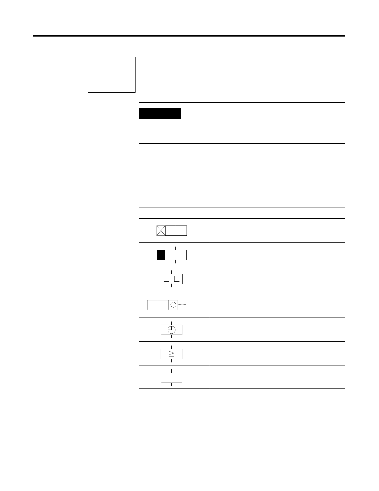
Draw a Circuit Diagram with Pico 4-19
I1-I2-------SQ1
...
...
I2----------RQ1
Function Relay Types
Use relay functions ’S’ and ’R’ only once per relay. If both coils are
triggered at the same time, priority is given to the coil further down in
the circuit diagram. This is shown in the preceding signal diagram in
section ’B’.
IMPORTANT
A latched relay is automatically switched off if the
power fails or if the device is in Stop mode.
Exception: Retentive coils retain signal 1 (see What is
Retention? on page 7-1).
The function relays are used to simulate some of the devices used in
conventional relay control systems. Pico provides the following
function relay types:
Circuit Diagram Symbol Function Relay Type
Timing relay, on-delayed
Timing relay, on-delayed with random switching
Timing relay, off-delayed
Timing relay, off-delayed with random switching
Timing relay, single pulse
Timing relay, flashing
DC
R
Counter relay, up/down counter
Time switch, weekday/time
(only in Pico models with real time clock)
Analog comparator relay
(only in Pico 24V dc models)
Text d i spl a y
A function relay is started via its relay coil or by evaluating a
parameter. It switches the contact of the function relay according to its
function and the set parameters. Current actual values are erased if the
power is turned off or if the unit is switched to Stop mode.
Exception: Retentive coils retain their signal (see Chapter 7).
Publication 1760-UM001D-EN-P - September 2005
Page 80

4-20 Draw a Circuit Diagram with Pico
In timing and counter relays, it is also possible to change the
switching behavior via the coil function.
ATTENTION
In Run mode, Pico processes the function relays after
a pass through the circuit diagram. The last state of
the coils is used for this.
Only use the coil of a function relay once.
Exception: The same coil can be used several times
when working with jumps.
Publication 1760-UM001D-EN-P - September 2005
Page 81

Draw a Circuit Diagram with Pico 4-21
Example with Timing and Counter Relays
A warning light flashes when the counter reaches 10.
Hard-Wire with Relays
S1
S2
CNTR1
T1
+24V
CNTR1
Count
Reset
T1
2.00 sec
PL1
R
0V
F1
I5---------CC1
I6---------RC1
C1---------TT1
T1---------{Q1
S2
S1
+24 V
com
12
Q 1
0V
M1
I5 I6
Publication 1760-UM001D-EN-P - September 2005
Page 82

4-22 Draw a Circuit Diagram with Pico
Use Circuit Diagram Forms
You can use the circuit diagram form on page B-1 of this manual for
planning and preparing your Pico circuit diagrams. An example form
is shown below and on the next page.
Customer: Program:
Date: Page:
J. Smith Ltd.
5-1-00
Comment:
Counter (Value 10)
Reset Counter
Trigger flash/blink relay
Warning light, flash 2s
Warning Light
1
Publication 1760-UM001D-EN-P - September 2005
Page 83

Draw a Circuit Diagram with Pico 4-23
Customer: Program:
Date: Page:
J. Smith Ltd.
5-1-00
Timing relays
:
TRG T
RES
:
::
TRG T
RES
Analog comparators
ANALOG
A
ANALOG ANALOG
Timing switches
-
-
Warning Light
2
::
TRG T
RES
AA
-
ON
OFF
:
:
Up/down counters
DIR
CNT
RES
DIR
CNT
RES
:
:
ON
OFF
C
ON
OFF
C
DIR
CNT
RES
:
:
C
Publication 1760-UM001D-EN-P - September 2005
Page 84

4-24 Draw a Circuit Diagram with Pico
I5----------CC1
C1 N +
S
+0
C1 N +
S
00000
C1 N +
S
00010
1. Enter the circuit diagram up to CC1.
CC1 is the contact of counter relay 1. If the cursor is on the
contact number, Pico will call up the parameter display when
you press Ok.
2. Move the cursor onto the 1 in CC1 and press Ok.
The parameter set for the counter is displayed.
3. Move the cursor onto the plus sign to the right of the S
(setpoint) and press Ok.
4. Change the counter setpoint to 10:
Use the left and right buttons to move the cursor onto the tens
digit.
Use the up and down buttons to modify the value of the digit.
5. Press Ok to save the value and Esc to return to the circuit
diagram. Pico has specific parameter displays for function relays.
The meaning of these parameters is explained under each relay
type.
I5----------CC1
I6----------RC1
C1----------TT1
T1 Ü S +
I1
+0
I2
+0
T:
T1 Ü S +
I1
01.000
I2
00.500
T:
6. Enter the circuit diagram up to contact ’TT1’ of the timing relay.
Set the parameters for T1.
The timing relay works like a flasher/blink relay. The Pico
symbol for the flasher/blink relay is shown in the screen to the
left. It is set at the top left of the parameter display.
7. Press the down arrow and select the flasher/blink relay symbol.
8. Use the right arrow to move to the first time setpoint I1.
9. Press Ok, then press the right arrow.
10. Use the arrows to enter the value 01.000 and press Ok.
The time setpoint I1 for the pause time is 1 second.
11. Use the down arrow to enter the value of the second setpoint I2.
Set this value to 0.5 seconds. This is the time value for the pulse
time.
Publication 1760-UM001D-EN-P - September 2005
12. Press Esc to leave the parameter entry.
The values are now stored.
Page 85

Draw a Circuit Diagram with Pico 4-25
I5----------CC1
I6----------RC1
C1----------TT1
T1----------{Q1
C1 N +
S
0010
C: 0000
C1 N +
S
0010
C: 0007
C1 N +
S
0010
13. Complete the circuit diagram.
14. Press Ok to store the circuit diagram.
Test Circuit Using Power Flow Display
1. Switch Pico to Run mode and return to the circuit diagram.
Each parameter set can be displayed using the power flow
display for the circuit diagram.
2. Move the cursor onto C1 and press Ok.
The parameter set for the counter is displayed with actual and
setpoint values.
3. Switch I5. The actual value changes.
This is represented in the Pico parameter display. In the last line C:
0007 the counter actual value is equal to seven.
If the actual value is greater than or equal to the setpoint (10), the left
character on the bottom row changes to a black box. The contact of
counter C1 switches.
C: 0010
T1 Ü S +
S1
00.500
S2
00.250
00.200
T:
The counter contact triggers the timing relay. This causes the warning
light to flash at output Q1.
Double the flashing frequency:
1. Select T1 in the power flow display and press Ok.
2. Change the set time I1 to 00.500 and I2 to 00.250
(0.5 and 0.25 s).
3. Press Ok to save the set time.
The character on the left of the bottom row indicates whether the
contact has switched or not.
Protect Timer and Counter Settings
You can also modify parameter settings via the PARAMETER menu
option. If you want to prevent other people from modifying the
parameters, change the access enable symbol from ’+’ to ’-’ when
creating the circuit diagram and protect the circuit diagram with a
password.
Publication 1760-UM001D-EN-P - September 2005
Page 86

4-26 Draw a Circuit Diagram with Pico
Timing Relays
I5-I4-------TT1
T1----------{Q3
Pico provides sixteen different timing relays, T1 to T16.
A timing relay is used to change the switching duration and the make
and break times of a relay contact. The possible delay times range
between 2 ms and 100 hours. You can use positive values, values of
analog inputs, and actual values of counter relays and timing relays.
IMPORTANT
The timing relays of Pico Series B controllers
function in the same way as the timing relays of Pico
Series A controllers.
The one exception is the ’flash’ function. Pico Series
B starts with the pulse. In Series A controllers the
’flash’ function starts with the pause. If required, the
same timing relays can also be used for retentive
data.
You integrate a timing relay into your circuit in the form of a contact
and coil.
Contact Coil
T1 to T16 Contact of a timing relay
TT1 to TT16 Enable, timing relay trigger
RT1 to RT16 Reset coil of the timing relay
HT1 to HT16 Stop coil of the timing relay (H=Stop, S means the Set
coil function
IMPORTANT
To prevent unpredictable switching states, use each
coil of a relay only once in the circuit diagram.
Publication 1760-UM001D-EN-P - September 2005
Page 87

T1 X S +
I1
00.000
I2
00.000
T:
Draw a Circuit Diagram with Pico 4-27
Parameter Display and Parameter Set for a Timing Relay
T1 Timing relay number 1
X On-delayed mode
S Time range in seconds
+ • + appears in the Parameter menu
• - does not appear in the Parameter menu
I1 Time setpoint 1:
• Positive value, I7, I8, I11, I12
• Actual value T1 to T16, C1 to C16
I2 Time setpoint 2:
• Positive value, I7, I8, I11, I12
• Actual value T1 to T16, C1 to C16
T: Display of actual value in Run mode
In the parameter display of a timing relay you can change the mode,
the time base, the time setpoint 1, time setpoint 2 (if necessary) and
the enable of the parameter display.
Compatibility Between Pico Series A and Pico Series B Controllers
New functions have been added to the parameter display of the Pico
Series B Controllers. The Series A parameters can be found at the
following points:
Pico Series A
Pico Series A Pico Series B
X
X
S
AA.BB
S
AA.BB
TRG
TRG
{
{
RES
RES
Actual value of elapsed time
Contact has not switched
Contact has switched
T1 = T1
X=X
S=S
T1
AA.BB = AA.BB
T1
+=+
T1 X S +
I1
10.000
I2
00.000
T:
03.305
T1 X S +
T1 X S +
I1
AA.BB
I1
AA.BB
I2
I2
T:
T:
Mode, time base
Time setpoint 1
Time setpoint 2
Publication 1760-UM001D-EN-P - September 2005
Page 88

4-28 Draw a Circuit Diagram with Pico
Tas k:
Turn on output Q1 1.5 min.
after actuation via I1.
Disable T2 via I2.
Programming a Timing Relay
A timing relay is integrated into your circuit in the form of a contact.
The function of the relay is defined via the parameter display. The
relay is started via the trigger input TRG and can be reset via the reset
input RES. A timer also resets when it is turned off. To prevent
unpredictable switching states, use each coil of a relay only once in
the circuit diagram.
Circuit Diagram:
I1---------TT2
I2---------RT2
2
T
--------{Q1
Parameter Display:
T2 X M:S +
I1
01.500
I2
00.000
T:
00.000
At least two elements are needed in the circuit diagram for a timing
relay:
• A relay contact in the contact field, in this case T2.
• A trigger coil in the coil field, in this case TT2.
You can also wire up the reset coil RT2 if you wish to use an external
reset signal. Enter the number of the relay contact T2 and press Ok.
The parameter set for timing relay T2 is displayed. Specify the
function of the relay.
Parameters for Timers
The parameter display for a timing relay is used to modify the
switching function, setpoint time and timebase units and to enable or
disable parameter access.
Switch Function
Timebase Units
T1 S +
I1
00.000
I2
30.000
T:
00.000
Parameter Display
Current Value
Setpoint
Publication 1760-UM001D-EN-P - September 2005
The coil terminals are not shown if you access the parameters via the
PARAMETER menu option. The actual time is only displayed in Run
mode. To view the actual time, call up the parameter display via the
power flow display or using the PARAMETER option.
Page 89

Draw a Circuit Diagram with Pico 4-29
Switch Function
Description
Parameters
X
?X
Switch with on-delay
Switch with on-delay and random time range
Switch with off-delay
X
Switch with off-delay and random time range
Switch with single-pulse
Switch with flashing
Typically, delay times are >40 ms for the 1760-L12xxx and >80 ms for
the 1760-L18xxx. This is because a time value less than the maximum
scan time of the Pico controllers may cause uncontrolled switching
states.
Time Units and Setpoint Time Parameters Resolution
S 00.00 Seconds 10 x milliseconds, 00.00 to 99.99 10 ms
M:S 00:00 Minutes: seconds, 00:00 to 99:59 1 s
H:M 00:00 Hours: minutes, 00:00 to 99:59 1 min.
X?X
Parameter Set Displayed via the PARAMETER Menu Option
+ Access enabled - Access disabled
Timing Relays, On-Delay, Without and With Random Switching
The relay switches a contact after the setpoint delay has elapsed. With
random switching, the relay contact switches randomly at any time up
to the specified time value (shown shaded in figure).
Timing Diagram
Trigger
Reset
Output
On
On
On
ttt
ABC
Publication 1760-UM001D-EN-P - September 2005
Page 90

4-30 Draw a Circuit Diagram with Pico
The trigger input starts the time (t). If the trigger input is disabled after
the time has elapsed, timer is reset and the output is turned off (A). If
the trigger coil drops out before the time has elapsed, the contact is
not turned on (B). The reset coil has priority over the trigger coil and
always resets the timer and turns the output off (C). If the preset is set
to zero, the output follows immediately after the trigger signal.
Typical applications include:
• Switching conveyor belts on or off after a delay
• Detecting gaps in the switching of sensors in the event of a fault
• Automatic window shutter control with random switching times
Timing Relays, Off-Delayed With and Without Random Switching
The relay switches a contact immediately and then resets it after the
setpoint delay has elapsed. With random switching, the relay contact
switches randomly at any time up to the specified time value (shown
?
shaded in figure).
Timing Diagram
Tri gg er
Reset
Output
On
On
On
tt
ABC
The trigger coil switches the contact. If the trigger coil (A) drops out,
the setpoint time starts and resets the contact after the time has
elapsed. The reset coil has priority over the trigger coil and always
resets the relay contact (B, C). If the time is set to zero, the contact
follows immediately after the trigger signal.
Typical applications include:
Publication 1760-UM001D-EN-P - September 2005
• Activating the deceleration of motors or fans
• Automatic lighting control for vacant buildings with random
switching times
Page 91

Draw a Circuit Diagram with Pico 4-31
Timing Relays, Single Pulse
The relay switches a contact for a time equal to the delay time set,
regardless of the length of the trigger signal.
Signal Diagram:
Trigger
Reset
Output
On
On
On
tt
The reset coil has priority over the trigger coil and resets the relay
contact before the time has elapsed. If the time is set to zero, the
contact is set for the duration of one program scan.
The cycle time varies according to the length of the circuit diagram.
Typical applications include:
• Adjusting switching signals to a defined pulse length
• Shortening pulses to the duration of a cycle (one-shot)
= flash
Timing Relays, Flashing
The relay closes and opens the relay contact alternately with the
flashing frequency.
Flash Frequency
EXAMPLE
Set Time: 0.2s, Flash Frequency
----------------------- ---------=
2Set Time×
1
1
----------2.5 Hz==
0.4s
Publication 1760-UM001D-EN-P - September 2005
Page 92

4-32 Draw a Circuit Diagram with Pico
Signal Diagram:
Tri gg er
Reset
Output
On
OnOn
On
ttt
The trigger coil enables the flashing on and off. The flashing period
starts with switch position ‘off’. The reset coil has priority over the
trigger coil and always resets the relay contact.
If the time is set to zero, the flash frequency changes with the cycle
time. The cycle time varies according to the length of the circuit
diagram.
A typical application is activating warning lamps.
Counter Relays
DC
Pico works with counter relays C1 to C16.
The counter relay adds or subtracts pulses and switches if the actual
value is greater than or equal to the setpoint value. Values between
R
0000 and 9999 are possible.
A counter relay can be controlled via the counting pulse CCx,
counting direction DCx and reset RCx relay functions.
Publication 1760-UM001D-EN-P - September 2005
Page 93

Signal Diagram:
Draw a Circuit Diagram with Pico 4-33
Count
Direction
Reset
Output
CCx
DCx
RCx
On
On
BACD
OnOn
8
7
6
5
4
3
2
1
0
On
The relay contact of a counter with setpoint value 6 switches when
the actual value is 6 (A). If the counting direction is reversed (B), the
contact switches off when the actual value is 5. Without a counting
pulse, the actual value is retained (C). The reset coil resets the counter
to 0 (D).
Possible applications include the counting of components, lengths or
event frequency.
Program a Counter Relay
You can integrate a counter relay into your program in the form of a
contact and coil. Counter relay C1 receives counting pulses via the
count coil CC1. The counting direction can be changed via the
direction coil DC1:
• If DC1 = 0, relay C1 counts up.
• If DC1 = 1, relay C1 counts down.
The Reset coil RC1 is used to reset the counter to 0.
Contact C1 is used to process the result of the counter in the circuit
diagram. To prevent unpredictable operation, use each coil of a relay
only once in the circuit diagram.
Enter at least one contact and a coil in your circuit diagram:
• A relay contact in the contact field, in this case C1
• A count coil in the coil field, in this case CC1
Publication 1760-UM001D-EN-P - September 2005
Page 94

4-34 Draw a Circuit Diagram with Pico
z
I1---------CC1
I3---------DC1
I2---------RC1
--------{Q1
C
1
You can wire up coils RC1 and DC1 as required. Select relay contact
C1, move the cursor to 1 and press Ok.
The parameter set for counter relay C1 is displayed.
Determine Counter Frequency
0005
DIR
CNT
{
RES
{
The maximum counter frequency depends on the length of the circuit
diagram in Pico. The number of contacts, coils and circuit connections
used determines the scan time (cycle time) required to process the
C1
Pico circuit diagram.
+
EXAMPLE
When using a Pico with only three circuit
connections for counting, resetting and outputting
the result via the output, the counter frequency may
be 100 Hz.
To determine the scan time refer to Determine Cycle Time of Circuit
Diagrams on page 8-3.
The maximum counter frequency depends on the maximum scan
time.
Use the following formula to determine the maximum counter
frequency:
1
--------------
f
c
2t
×
0.8×=
c
Publication 1760-UM001D-EN-P - September 2005
f
= maximum counter frequency
c
t
= maximum scan time
c
0.8 = correction factor
EXAMPLE
The maximum scan time is t
1
---------------------
f
c
24 ms×
=×=
0.8 100 H
= 4000 µs (4 ms).
c
Page 95

C2 N +
S
00.000
Draw a Circuit Diagram with Pico 4-35
Parameters for Counters
The parameter display for counters is used to change the counter
setpoint value and to enable or disable parameter access.
C2 Counter function relay number 2
N • Mode N: up/down counter
• Mode H: high-speed up/down counter
• Mode F: frequency counter
+ • + appears in the Parameter menu
• - does not appear in the Parameter
menu.
S Setpoint, constant from 00000 to 32000
Parameter Coil Function Meaning
DIR DC1 to DC16 Counting direction
Coil not triggered: count up
Coil triggered: count down
CNT CC1 to CC16 Counting pulse
RES RC1 to RC16 Reset, coil triggered: actual value reset to
00000
The symbol ‘
{‘ before DIR, CNT and RES indicates whether the coil
function is programmed in the circuit diagram.
Parameters Displayed via the PARAMETER Menu Option
+ Access enabled - Access disabled
The actual value is only displayed in Run mode. The parameter
display can then be called via the power flow display or via the
PARAMETER option from the main menu.
The coil symbol is not displayed if you select the parameter display
via the PARAMETER menu option.
The counter relay counts between 0 and 32000.
When the Pico is in Run mode and the value of 32000 is reached, this
value is retained until the count direction is changed. If the value of
Publication 1760-UM001D-EN-P - September 2005
Page 96

4-36 Draw a Circuit Diagram with Pico
00000 is reached, this value is retained until the count direction is
changed.
Compatibility between Pico Series A Controllers and Pico Series B Controllers
High Speed Counters
0230
DIR
{
CNT
{
RES
{
0000
C1
+
AAAA = S AAAAA
C1 = C1
+=+
C1 N +
S
AAAAA
Pico provides various high-speed counter functions. These counter
function blocks are coupled directly to digital inputs. The following
functions are possible:
• Frequency counters: C15 and C16
• High-speed counters: C13 and C14
Frequency Counters
Pico provides two frequency counters, C15 and C16, for use as
required. The frequency counters can be used for measuring
frequencies. The high-speed frequency counters are permanently
connected to the digital inputs I3 and I4.
Publication 1760-UM001D-EN-P - September 2005
Frequency counters C15 and C16 can be used for determining motor
speeds, volume measurement using volume meters or the running of
a motor.
The frequency counter allows you to enter an upper threshold value
as a comparison value. The C15 and C16 frequency counters are not
dependent on the cycle time.
Counter Frequency and Pulse Shape
The maximum counter frequency is 1 kHz and the minimum counter
frequency is 4 Hz. The signals must be square waves with a
mark-to-space ratio of 1:1. If this is not the case, then the minimum
mark-to-space ratio is 0.5 ms.
t
t
min
0.5
1
---------
×=
f
max
= minimum time of the pulse or pause duration
min
= maximum count frequency (1 kHz)
f
max
Page 97

Draw a Circuit Diagram with Pico 4-37
IMPORTANT
Frequency counters operate independently of the
program cycle time. The result of the actual value
setpoint comparison is only transferred once every
program cycle for processing in the circuit diagram.
The reaction time in relation to the setpoint/actual
value comparison can therefore be up to one cycle.
Measurement Method
The pulses on the input are counted for one second regardless of the
cycle time, and the frequency is determined. The measurement result
is provided as an actual value.
Wire a Frequency Counter
The following assignment of the digital inputs apply.
• I3 counter input for frequency counter C15.
• I4 counter input for frequency counter C16.
-----------CC15
CC15--------SQ3
I8-----------
RC15
IMPORTANT
If you use C15 or C16 as frequency counters, coils
DC15 or DC16 will have no function. The counter
signals are transferred directly from the digital inputs
I3 and I4 to the counters. A frequency counter
measures the actual value and does not measure a
direction.
You only integrate a frequency counter into your circuit in the form of
a contact and enable coil. The coils and contacts have the following
meanings:
Contact Coil Description
C15 to C16 The contact switches if the actual
value is greater than or equal to the
setpoint.
CC15, CC16 Enable of the frequency counter on ’1’
state, coil activated.
RC15, RC16 Reset, coil triggered: actual value reset
to 00000.
Publication 1760-UM001D-EN-P - September 2005
Page 98

4-38 Draw a Circuit Diagram with Pico
C15 F +
S
00200
IMPORTANT
The frequency counter can also be enabled
specifically for a special operating state. This has the
advantage that the cycle time of the device is only
burdened with the frequency measurement when it
is taking place. If the frequency counter is not
enabled, the cycle time of the device is shorter.
Parameter Display and Parameter Set for Frequency Counter
C15 Counter function relay number 15
F Mode F: frequency counter
+ • + appears in the Parameter menu.
• - does not appear in Parameter menu.
S Setpoint, constant from 00000 to 01000 (32000 is a possible setting, the
maximum frequency is 1 kHz).
In the parameter display of a counter relay you change the mode, the
setpoint and the enable of the parameter display.
Value Range
The counter relay counts between 4 and 1000 (Hz).
Parameter display in Run mode:
C15 F +
S
00200
C:00153
Current setpoint, constant
Contact has not switched.
Contact has switched. Actual value (0153)
Retention
Setting retention on the frequency counter serves no purpose since
the frequency is continuously measured.
Publication 1760-UM001D-EN-P - September 2005
Page 99

Function of the Frequency Counter
1: Counter input I3 or I4.
2: Upper Setpoint.
3: Enable coil CC...
4: Reset coil RC...
5: Contact (make contact) C... upper setpoint value reached.
tg: Gate time for the frequency measurement.
• Range A: The counter is enabled. Contact C15 (C16)
switches after a frequency above the setpoint was
measured for the first time.
• Range B: If the actual value falls below the setpoint,
the contact is reset. The removal of the enable signal
resets the actual value to zero.
• Range C: The counter is enabled. After a frequency
above the setpoint was measured for the first time,
contact C15 (C16) switches.
• Range D: The reset coil resets the actual value to zero.
Draw a Circuit Diagram with Pico 4-39
1
2
A
3
4
5
t
t
g
t
g
t
g
g
BC
t
t
g
g
D
t
t
g
t
g
g
High Speed Counter
You can use the high-speed counters to count high frequency signals
reliably.
Pico provides two high-speed up/down counters, C13 and C14, for
use as required. The high-speed counter inputs are permanently
connected to the digital inputs I1 and I2. These counter relays allow
you to count events independently of the cycle time.
The high-speed counters allow you to enter an upper threshold value
as a comparison value. The C13 and C14 high-speed counters are not
dependent on the cycle time.
Counter Frequency and Pulse Shape
The maximum counter frequency is 1 kHz.
The signals must be square waves. We recommend a mark-to-space
ratio of 1:1.
If this is not the case: The minimum mark-to-space ratio is 0.5 ms.
t
min
0.5
t
1
---------
×=
f
max
= minimum time of the pulse or pause duration
min
f
= maximum count frequency (1 kHz)
max
Publication 1760-UM001D-EN-P - September 2005
Page 100

4-40 Draw a Circuit Diagram with Pico
-----------CC13
C13--------SN3
I6---------DC13
I8-C13-----RC13
IMPORTANT
High-speed counters operate independently of the
program cycle time. The results of the actual value
setpoint comparison is only transferred once every
program cycle for processing in the circuit diagram.
The reaction time in relation to the setpoint/actual
value comparison can therefore be up to one cycle
in length.
Wire a High-Speed Counter
The following assignment of the digital inputs apply.
• I1: High-speed counter input for counter C13.
• I2: High-speed counter input for counter C14.
IMPORTANT
You integrate a high-speed counter into your circuit in the form of a
contact and coil.
The coils and contacts have the following meanings:
If you use C13 or C14 as high-speed counters you
must enable them with the coil CC13 or CC14
accordingly.
Publication 1760-UM001D-EN-P - September 2005
Contact Coil
C13 to C14 The contact switches if the actual value is greater than
or equal to the setpoint.
CC13, CC14 Enable of the high-speed counter on 1 signal coil
activated.
DC13, DC14 Counting direction:
• Status 0, not activated, up counting.
• Status 1, activated, down counting.
RC13, RC14 Reset, coil triggered: Actual value reset to 00000.
IMPORTANT
The high-speed counter can also be enabled
specifically for a special operating state. This has the
advantage that the cycle time of the device is only
burdened with the counting when it is taking place.
If the high-speed counter is not enabled, the cycle
time of the device is shorter.
 Loading...