

Page 1
Installation Instructions
ControlLogix DeviceNet Scanner Module
Catalog Numbers 1756-DNB, Series C and D
Topic Page
Important User Information 2
Preventing Electrostatic Discharge 3
European Hazardous Location Approval - European Zone 2 Certification 4
Environment and Enclosure 5
North American Hazardous Location Approval 6
About this Publication 6
About the Module 7
Before You Begin 7
Determine Module Slot Location 8
Change Module Settings 9
Install the Module in the Chassis 16
Configure the Scan List 27
Monitor and Troubleshoot Devices in the Module Scan List 27
Interpret the Status Indicators 35
Understand ControlLogix Controller Interface Structures 38
Specifications 43
Additional Resources 47
Page 2
2 ControlLogix DeviceNet Scanner Module
Important User Information
Solid state equipment has operational characteristics differing from those of electromechanical
equipment. Safety Guidelines for the Application, Installation and Maintenance of Solid State Controls
Publication SGI-1.1
http://literature.rockwellautomation.com
equipment and hard-wired electromechanical devices. Because of this difference, and also because of
the wide variety of uses for solid state equipment, all persons responsible for applying this equipment
must satisfy themselves that each intended application of this equipment is acceptable.
In no event will Rockwell Automation, Inc. be responsible or liable for indirect or consequential damages
resulting from the use or application of this equipment.
The examples and diagrams in this manual are included solely for illustrative purposes. Because of the
many variables and requirements associated with any particular installation, Rockwell Automation, Inc.
cannot assume responsibility or liability for actual use based on the examples and diagrams.
No patent liability is assumed by Rockwell Automation, Inc. with respect to use of information, circuits,
equipment, or software described in this manual.
Reproduction of the contents of this manual, in whole or in part, without written permission of Rockwell
Automation, Inc., is prohibited.
Throughout this manual, when necessary, we use notes to make you aware of safety considerations.
WARNING
available from your local Rockwell Automation sales office or online at
Identifies information about practices or circumstances that can cause an explosion in
a hazardous environment, which may lead to personal injury or death, property
damage, or economic loss.
) describes some important differences between solid state
IMPORTANT
ATTENTION
SHOCK HAZARD
BURN HAZARD
Publication
Identifies information that is critical for successful application and understanding of
the product.
Identifies information about practices or circumstances that can lead to personal
injury or death, property damage, or economic loss. Attentions help you identify a
hazard, avoid a hazard and recognize the consequences.
Labels may be on or inside the equipment (for example,a drive or motor) to alert
people that dangerous voltage may be present.
Labels may be on or inside the equipment (for example, a drive or motor) to alert
people that surfaces may reach dangerous temperatures.
1756-IN566D-EN-P - June 2008
Page 3
ControlLogix DeviceNet Scanner Module 3
Preventing Electrostatic Discharge
ATTENTION
This equipment is sensitive to electrostatic discharge, which can cause
internal damage and affect normal operation. Follow these guidelines when
you handle this equipment:
• Touch a grounded object to discharge potential static.
• Wear an approved grounding wriststrap.
• Do not touch connectors or pins on component boards.
• Do not touch circuit components inside the equipment.
• Use a static-safe workstation, if available.
• Store the equipment in appropriate static-safe packaging when not in use.
Publication
1756-IN566D-EN-P - June 2008
Page 4

4 ControlLogix DeviceNet Scanner Module
European Hazardous Location Approval - European Zone 2 Certification
The following applies when the product bears the EEx Marking).
This equipment is intended for use in potentially explosive atmospheres as
defined by European Union Directive 94/9/EC.
The LCIE (Laboratoire Central des Industries Electriques) certifies that this
equipment has been found to comply with the Essential Health and Safety
Requirements relating to the design and construction of Category 3
equipment intended for use in potentially explosive atmospheres, given in
Annex II to this Directive.
Compliance with the Essential Health and Safety Requirements has been
assured by compliance with EN 60079-15.
IMPORTANT
Publication
• This equipment is not resistant to sunlight or other sources of UV
radiation.
• This equipment must be installed in an enclosure providing at least IP54
protection when applied in Class I, Zone 2 environments.
• This equipment shall be used within its specified ratings defined by
Rockwell Automation.
• Provision shall be made to prevent the rated voltage from being exceeded
by transient disturbances of more than 40% when applied in Class I, Zone
2 environments.
• This equipment must be used only with ATEX certified backplanes.
1756-IN566D-EN-P - June 2008
Page 5

Environment and Enclosure
ControlLogix DeviceNet Scanner Module 5
ATTENTION
This equipment is intended for use in a Pollution Degree 2 industrial
environment, in overvoltage Category II applications (as defined in IEC
publication 60664-1), at altitudes up to 2000 m (6562 ft) without derating.
This equipment is considered Group 1, Class A industrial equipment according
to IEC/CISPR Publication 11. Without appropriate precautions, there may be
potential difficulties ensuring electromagnetic compatibility in other
environments due to conducted as well as radiated disturbance.
This equipment is supplied as open-type equipment. It must be mounted within
an enclosure that is suitably designed for those specific environmental
conditions that will be present and appropriately designed to prevent personal
injury resulting from accessibility to live parts. The enclosure must have
suitable flame-retardant properties to prevent or minimize the spread of flame,
complying with a flame spread rating of 5VA, V2, V1, V0 (or equivalent) if
non-metallic. The interior of the enclosure must be accessible only by the use
of a tool. Subsequent sections of this publication may contain additional
information regarding specific enclosure type ratings that are required to
comply with certain product safety certifications.
Besides this publication, see:
• Industrial Automation Wiring and Grounding Guidelines, for additional
installation requirements, Allen-Bradley publication 1770-4.1
• NEMA Standards publication 250 and IEC publication 60529, as
applicable, for explanations of the degrees of protection provided by
different types of enclosure.
.
Publication
1756-IN566D-EN-P - June 2008
Page 6
6 ControlLogix DeviceNet Scanner Module
North American Hazardous Location Approval
The following information applies when
operating this equipment in hazardous
locations.
Products marked "CL I, DIV 2, GP A, B, C, D" are suitable for
use in Class I Division 2 Groups A, B, C, D, Hazardous
Locations and nonhazardous locations only. Each product is
supplied with markings on the rating na meplate indicating
the hazardous location temperature code. When
combining products within a system, the most adverse
temperature code (lowest "T" number) m ay be used to help
determine the overall temperature code of the system.
Combinations of equipment in your system are subject to
investigation by the local Authorit y Having Jurisdiction at
the time of installation.
WARNING
EXPLOSION HAZARD -
• Do not disconnect eq uipment unless
power has been removed or the
area is known to be nonhazardous.
• Do not disconnect connections to
this equipment unless power has
been removed or the area is known
to be nonhazardous. Secure any
external connections that mate to
this equipment by using screws,
sliding latches, threaded
connectors, or other means
provided with this product.
• Substitution of components may
impair suitability for Class I,
Division 2.
• If this product contains batteries,
they must only be changed in an
area known to be nonhazardous.
Informations sur l’utilisation de cet
équipement en environnements dangereux.
Les produits marqués "CL I, DIV 2, GP A, B, C, D" ne
conviennent qu'à une utilisation en environnements de
Classe I Division 2 Groupes A, B, C, D dangereux et non
dangereux. Chaque produit est livré avec des marqua ges sur
sa plaque d'identification qui indiquent le code de
température pour les environnement s dangereux. Lorsque
plusieurs produits sont combinés dans un système, le code de
température le plus défavorable (co de de température le plus
faible) peut être utilisé pour déterminer le code de
température global du système. Les comb inaisons
d'équipements dans le système sont sujettes à inspection pa r
les autorités locales qualifiées au moment de l'installation.
AVERTISSEMENT
RISQUE D’EXPLOSION –
• Couper le courant ou s'assurer
que l'environnement est classé
non dangereux avant de
débrancher l'équipement.
• Couper le courant ou s'assurer
que l'environnement est classé
non dangereux avant de
débrancher les connecteurs. Fixer
tous les connecteurs externes
reliés à cet équipement à l'aide
de vis, loquets coulissants,
connecteurs filetés ou autres
moyens fournis avec ce produit.
• La substitution de composants
peut rendre cet équipement
inadapté à une utilisation en
environnement de Classe I,
Division 2.
• S'assurer que l'environnement est
classé non dangereux avant de
changer les piles.
About this Publication
Use this publication as a guide to install the module. This publication
describes hardware installation only. For configuration information, refer to
the DeviceNet Modules in Logix5000 Systems User Manual, publication
DNET-UM004
Publication
.
1756-IN566D-EN-P - June 2008
Page 7
ControlLogix DeviceNet Scanner Module 7
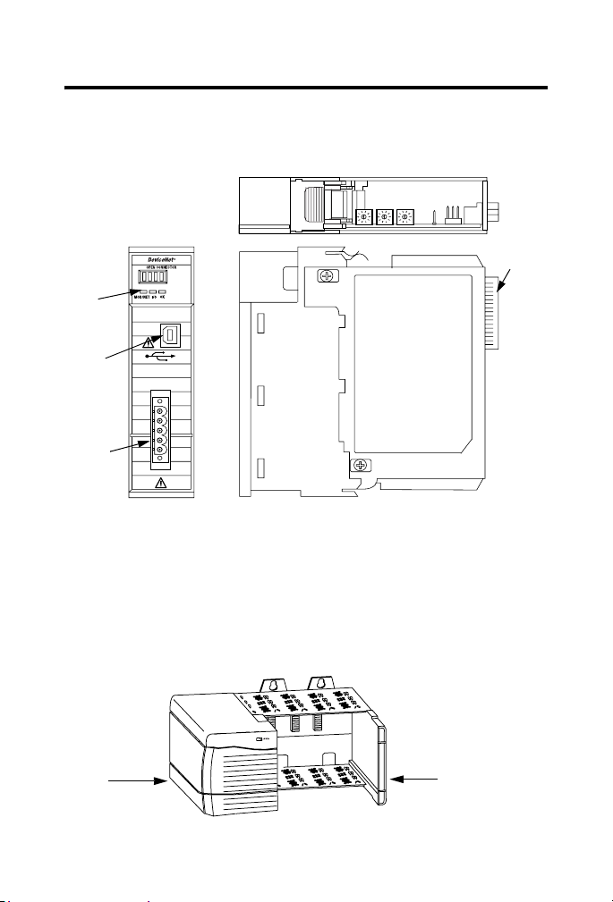
About the Module
Use this figure to identify the external features of the module.
Top View
Front
Panel
USB Port
DeviceNet
Port
Front View
Side View
Backplane
Connector
31713-M
Before You Begin
Before you install the module, you must install and connect a ControlLogix
chassis and power supply.
Power
Supply
20805-M
Publication
1756-A4
Chassis
1756-IN566D-EN-P - June 2008
Page 8
8 ControlLogix DeviceNet Scanner Module
To install these products, refer to these publications.
Publication References
Chassis Type Chassis
Installation
Instructions
Series B:
1756-A4, 1756-A7,
1756-A10, 1756-A13
Pub. No.
1756-IN080
Power Supply Power Supply
Installation
Instructions
1756-PA72/B Pub. No.
1756-PB72/B
1756-PA75/A Pub. No.
1756-PB75/A
1756-IN078
1756-IN596
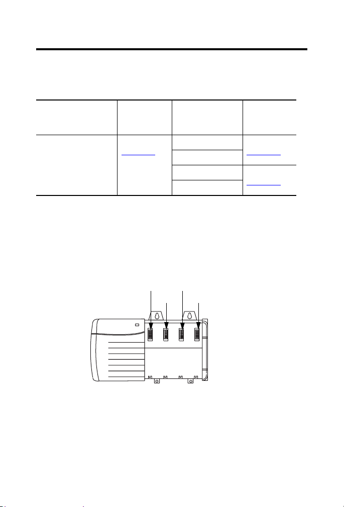
Determine Module Slot Location
Install the module in any slot in the ControlLogix chassis. You can install
multiple 1756-DNB scanner modules in the same chassis.
The following figure shows chassis slot numbering in a 4-slot chassis. Slot 0 is
the first slot and is always the leftmost slot in the chassis.
Slot 0
Power Supply
Slot 1
Slot 2
Slot 3
Chassis
20806
Publication
1756-IN566D-EN-P - June 2008
Page 9
ControlLogix DeviceNet Scanner Module 9
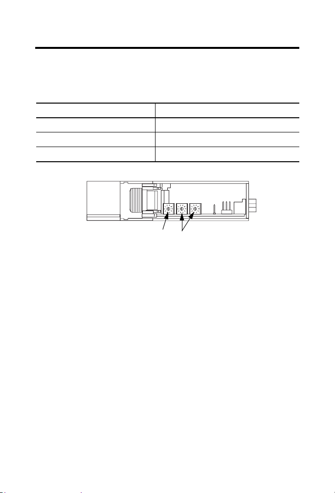
Change Module Settings
The module ships with these settings.
Factory Setting Values
Factory Settings Value
Rotary switches 999
Communication (data) rate Software settable (default 125 Kbps)
Node address Software settable (default 63)
Front of Module
Communication (Data)
Rate Rotary Switch
Top of Module
DeviceNet Node Address Rotary
Switches
Publication
1756-IN566D-EN-P - June 2008
31587
Page 10
10 ControlLogix DeviceNet Scanner Module
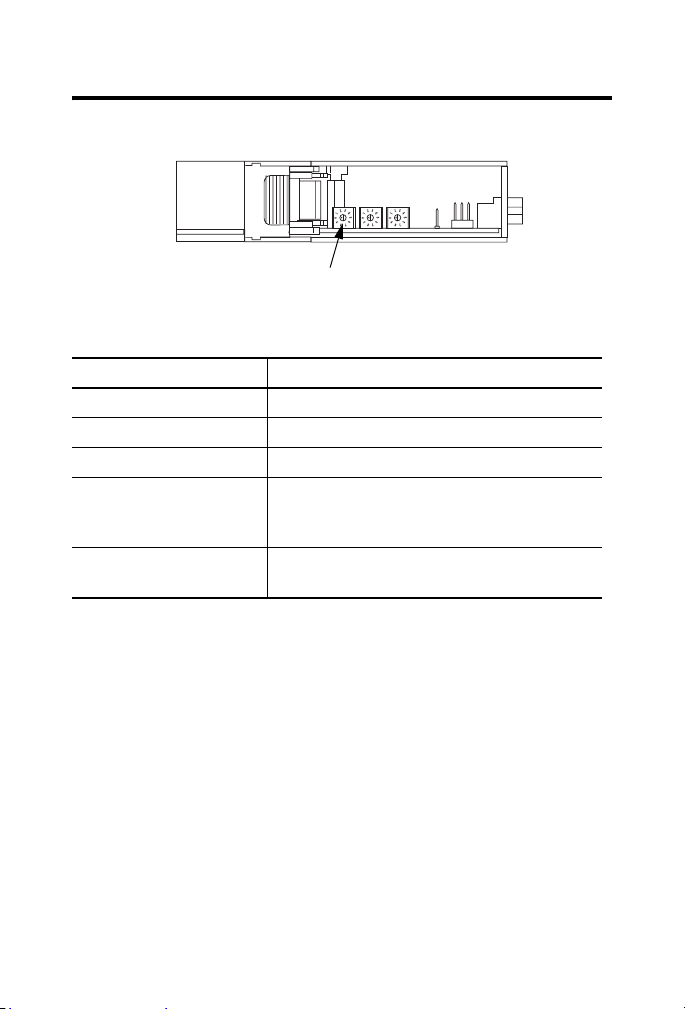
Set the Communication Rate
The 1756-DNB scanner module supports the following DeviceNet network
communication rates:
• 125 Kbps
• 250 Kbps
• 500 Kbps
The factory default setting is 125 Kbps.
ATTENTION
Do not change the communication rate on an active network. Unpredictable
operation may result. In addition, the new communication rate does not take
effect until you cycle power to the 1756-DNB scanner module.
Change the communication rate by setting the rotary switch or
commissioning the 1756-DNB scanner module in RSNetWorx for DeviceNet
software.
Use the switch to select a specific communication rate. When the switch is set
to 3...9 (except for 888), you can configure the communication rate with
RSNetWorx for DeviceNet software. When all three switches are set to 8, the
1756-DNB scanner module will reset to factory default settings at powerup.
See Restore the Factory Default Settings on page 15
See the following table for switch settings.
for more information.
Publication
1756-IN566D-EN-P - June 2008
Page 11
ControlLogix DeviceNet Scanner Module 11
Communication Rate Rotary Switch
Front of Module
Top of Module
Communication (Data) Rate Rotary Switch
Switch Settings and Communication Rate
Switch Setting Communication Rate
0 125 Kbps
1 250 Kbps
2 500 Kbps
8 When all three switches are set to 8, this resets the
1756-DNB scanner module to factory default settings.
Do not use for normal operation.
All other values Select the communication rate with RSNetWorx for
DeviceNet software.
31587
Publication
1756-IN566D-EN-P - June 2008
Page 12

12 ControlLogix DeviceNet Scanner Module
Set the Rotary Switch
Use the communication (data) rate rotary switch to change the
communication rate.
TIP
For ease of access, remove the module from the chassis before proceeding.
1. If the module is removed from the chassis, be sure that power is
removed or the area is nonhazardous before proceeding.
2. Move the rotary switch to the desired position.
3. If necessary, reinstall the module into the chassis.
Use RSNetWorx for DeviceNet Software
Follow this procedure to use RSNetWorx for DeviceNet software to set the
communication rate.
For more information, refer to the DeviceNet Modules in Logix5000 Control
Systems User Manual, publication DNET-UM004
1. In RSNetWorx for DeviceNet software, select the 1756-DNB scanner
module.
2. Select Tools and Node Commissioning.
3. Browse to the DeviceNet network for the 1756-DNB scanner module
you want to commission.
4. Select the 1756-DNB scanner module you want to commission.
.
Publication
1756-IN566D-EN-P - June 2008
Page 13
ControlLogix DeviceNet Scanner Module 13
5. In the Data Rate field, select the communication (data) rate.
6. Click Apply.
7. Cycle power to the 1756-DNB scanner module.
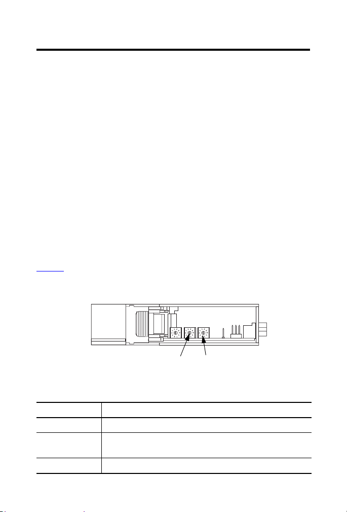
Set the Node Address
The 1756-DNB scanner module supports DeviceNet node addresses 00...63.
The factory default setting is node address 63.
Change the node address by setting the rotary switches or commissioning the
1756-DNB scanner module in RSNetWorx for DeviceNet software.
Use the switches to select any network address from 00 through 63. When
the switches are set outside of this range (except for 888), you can configure
the node address with RSNetWorx for DeviceNet software. When all three
switches are set to 8, the 1756-DNB scanner module will reset to factory
default settings at powerup. See Restore the Factory Default Settings on
for more information. See the following table for switch settings.
page 15
Switch Settings
Front of Module
Most Significant Digit Switch
DeviceNet Node Address Rotary Switches
Top of Module
Least Significant Digit Switch
Switch Settings
Switch Setting Node Address
0...63 DeviceNet node address 00...63
88 When all three switches are set to 8, resets the 1756-DNB scanner
module to factory default settings. Do not use for normal operation.
All other values Select the node address with RSNetWorx for DeviceNet software.
Publication
1756-IN566D-EN-P - June 2008
31587
Page 14

14 ControlLogix DeviceNet Scanner Module
Set the Rotary Switches
Use the node address rotary switches to change the DeviceNet node address
for the 1756-DNB scanner module.
TIP
For ease of access, remove the module from the chassis before proceeding.
1. If the module is removed from the chassis, be sure that power is
removed or the area is nonhazardous before proceeding.
2. Move the rotary switches to the desired position.
3. If necessary, reinstall the module into the chassis.
Use RSNetWorx for DeviceNet Software
Follow this procedure to use RSNetWorx for DeviceNet software to set the
node address.
For more information, refer to DeviceNet Modules in Logix5000 Control
Systems, publication DNET-UM004
1. In RSNetWorx for DeviceNet software, select the 1756-DNB scanner
module.
2. Click Tools>Node Commissioning.
3. Browse to the DeviceNet network for the 1756-DNB scanner module
you want to commission.
4. Select the 1756-DNB scanner module you want to commission.
.
5. In the Address field, select the node address.
6. Click Apply.
Publication
1756-IN566D-EN-P - June 2008
Page 15

ControlLogix DeviceNet Scanner Module 15
Restore the Factory Default Settings
The out-of-box reset will clear the scanlist (including ADR configuration
recovery files) and return all software setting attributes to their default values.
Follow this procedure to restore the factory default communication rate and
node address.
1. Set the switches to 888.
IMPORTANT
Do not use the 888 switch setting during normal module operation.
2. Restore power to the module.
When the out-of-box reset is complete, the alphanumeric display
repeatedly scrolls the message Reset Complete - Change Switch
Settings. During this time, the module does not respond to
communication from any port (including the backplane, DeviceNet
connector, or USB port).
3. After the module resets, perform the following steps.
a. Set the switches to the desired position.
b. Restore power to the module.
Publication
1756-IN566D-EN-P - June 2008
Page 16

16 ControlLogix DeviceNet Scanner Module
Install the Module in the Chassis
WARNING
Slide the module into the
chassis. Make sure the module
backplane connector properly
connects to the chassis
backplane.
When you insert or remove the module while backplane power is on, an electrical arc can
occur. This could cause an explosion in hazardous location installations.
Be sure that power is removed or the area is nonhazardous before proceeding. Repeated
electrical arcing causes excessive wear to contacts on both the module and its mating
connector. Worn contacts may create electrical resistance that can affect module
operation.
2
1
Align the circuit board with top and
bottom guides in the chassis.
Circuit Board
Publication
3
The module is properly installed when it is
flush with the power supply or other
installed modules.
1756-IN566D-EN-P - June 2008
31715-M
Page 17

ControlLogix DeviceNet Scanner Module 17
Wire the DeviceNet Connector
Use an open-style 5- or 10-position linear plug to connect to the DeviceNet
network. An open-style 10-position linear plug is provided with your module.
IMPORTANT
For detailed DeviceNet connection information, see the DeviceNet Media
Design and Installation Guide, publication DNET-UM072
Also see the Industrial Automation Wiring and Grounding Guidelines,
publication 1770-2.1
.
Wire the connector according to the following illustrations.
Color Chips (dots)
Red Dot
White Dot
Blue Dot
Black Dot
10-position Plug
10-position
Linear Plug
D
D
D
D
D
5-position Plug
Red
White
Bare
Blue
Black
.
DeviceNet
Drop Line or
Trunk Cable
20474-
Publication
1756-IN566D-EN-P - June 2008
Page 18

18 ControlLogix DeviceNet Scanner Module
Connect the Module to the DeviceNet Network
WARNING
If you connect or disconnect the DeviceNet connector with power applied to
this module or any device on the network, an electrical arc can occur. This
could cause an explosion in hazardous location installations.
Be sure that power is removed or the area is nonhazardous before proceeding.
Attach the connector to the module’s DeviceNet port as shown below.
Tighten the screws on the connector as needed.
10-position
Linear Plug
DeviceNet Port
Connector
DeviceNet Drop Line or Trunk
Connector
31716-M
Publication
1756-IN566D-EN-P - June 2008
Page 19

ControlLogix DeviceNet Scanner Module 19
Connect to the Module Via the USB Port
WARNING
The USB port is intended for temporary local programming purposes only and
is not intended for permanent connection. If you connect or disconnect the USB
cable with power applied to this module or any device on the USB network, an
electrical arc can occur. This could cause an explosion in hazardous location
installations.
Be sure that power is removed or the area is nonhazardous before proceeding.
A Samtec Inc. RSP-119350 USB cable is required to maintain hazardous
location certifications.
The module has a USB device port that uses a Series B receptacle. To use the
USB port, you must have RSLinx software, version 2.51 or higher, installed on
your computer.
Use a USB cable to connect your computer to the USB port. The connection
lets you download programs to controllers and configure modules directly
from your computer.
IMPORTANT
USB Port
• The USB port is designed for a temporary connection only.
• The USB cable is not to exceed 3.0 m (9.84 ft) and must not contain hubs.
DeviceNet Port
Publication
31592-M
1756-IN566D-EN-P - June 2008
Page 20

20 ControlLogix DeviceNet Scanner Module
Set Up the USB Driver
IMPORTANT
The 1756-DNB scanner module must be powered up before proceeding with
the USB driver setup.
To connect your 1756-DNB scanner module via a USB port, you need to first
set up a USB driver. To set up a USB driver, perform this procedure.
1. Connect your 1756-DNB scanner module via a USB port.
The Found New Hardware Wizard dialog appears.
2. Check Install the software automatically (Recommended).
3. Click Next.
Publication
1756-IN566D-EN-P - June 2008
Page 21

ControlLogix DeviceNet Scanner Module 21
These dialogs appear consecutively.
4. Click Finish to set up your USB driver.
Publication
1756-IN566D-EN-P - June 2008
Page 22

22 ControlLogix DeviceNet Scanner Module
5. In RSLinx software, from the Communications pull-down menu,
choose RSWho to view your module.
The RSLinx Workstation organizer appears.
Virtual Chassis Driver
USB Port Driver
Your module appears under two different drivers, a virtual chassis and the
USB port. You can use either driver to browse through your 1756-DNB
scanner module.
Flash Upgrade Firmware through a USB Port
You may flash upgrade the firmware for one module through a USB port.
IMPORTANT
Publication
The 1756-DNB scanner module must be powered up before proceeding with
the flash upgrade.
1756-IN566D-EN-P - June 2008
Page 23

ControlLogix DeviceNet Scanner Module 23
IMPORTANT
Do not simultaneously flash upgrade the firmware for more than one module
through a USB port. If you do, one or more of the flash updates may fail in
the middle of the download.
Apply Chassis Power
31717-M
Publication
1756-IN566D-EN-P - June 2008
Page 24

24 ControlLogix DeviceNet Scanner Module
Check Power Supply and Module Status
Check the status indicators and alphanumeric display to determine if the
power supply and module are operating properly. See see Monitor and
Troubleshoot Devices in the Module Scan List on page 27
.
I/O
MOD/NET
Power Supply indicator is green.
Alphanumeric
Display
OK indicator is red
during self-test,
then green.
When you apply chassis power, the alphanumeric display cycles through the
following information:
DeviceNet
MOD/NET I/O OK
TM
1. TEST
2. PASS
3. Firmware revision (Rev xx.xxx)
4. Node address (A#xx)
Alphanumeric
Display
For more information on the alphanumeric display or status codes, see
Monitor and Troubleshoot Devices in the Module Scan List on page 27.
Publication
1756-IN566D-EN-P - June 2008
Page 25

ControlLogix DeviceNet Scanner Module 25
Install or Remove the Module Under Power
You can install or remove this module while chassis power is applied.
WARNING
When you insert or remove the module while backplane power is on, an
electrical arc can occur. This could cause an explosion in hazardous location
installations. Be sure that power is removed or the area is nonhazardous
before proceeding. Repeated electrical arcing causes excessive wear to
contacts on both the module and its mating connector. Worn contacts may
create electrical resistance that can affect module operation.
Publication
1756-IN566D-EN-P - June 2008
Page 26

26 ControlLogix DeviceNet Scanner Module
Remove or Replace the Module
1
Push on upper and lower module tabs
to disengage them.
31719-M
2
31720-M
IMPORTANT
Publication
Slide module out of chassis.
If you want to replace an existing module with an identical one, and you
want to resume identical system operation, you must install the new module
in the same slot.
1756-IN566D-EN-P - June 2008
Page 27

ControlLogix DeviceNet Scanner Module 27
Configure the Scan List
Use RSNetWorx for DeviceNet software to configure the scan list for the
1756-DNB scanner module.
Refer to DeviceNet Modules in Logix5000 Control Systems,
publication DNET-UM004
.
Monitor and Troubleshoot Devices in the Module Scan List
Use the alphanumeric display and the status indicators on the 1756-DNB
scanner module front panel to verify networked devices in the scan list are
operating correctly.
Interpret the Alphanumeric Display
Your 1756-DNB scanner module displays alphanumeric codes that provide
diagnostic information about your module. The alphanumeric display flashes
the codes at approximately one-second intervals.
As an example, the display for RUN toggles between the node address and
the mode of the 1756-DNB scanner module:
A#01
RUN
If there is a problem, the display shows the MAC ID of the problem node,
then the error code. The display toggles through these elements until the error
is corrected:
A#01
RUN
N#33
E#72
Publication
1756-IN566D-EN-P - June 2008
Page 28

28 ControlLogix DeviceNet Scanner Module
Alphanumeric Status Messages
The following table summarizes the status messages.
Alphanumeric Status Message
Status Message Description
Run The 1756-DNB scanner module is in Run mode.
Idle The 1756-DNB scanner module is in Idle mode.
Auto AutoScan is enabled and the 1756-DNB scanner module is in Idle
mode.
Flash In Progress ControlFlash is transferring a flash image to the 1756-DNB scanner
module.
Duplicate Node
Failure
Bus Off Detected The 1756-DNB scanner module has detected errors on the
No Network Power No DeviceNet network power is being supplied to the 1756-DNB
NoRX - The 1756-DNB scanner module does not contact a scanlist.
NoTX The 1756-DNB module failed to transmit a message.
Reset Complete -
Change Switch
Settings
The node address of the 1756-DNB scanner module is already in
use by another device on the DeviceNet network.
DeviceNet network and has been taken offline.
scanner module.
- The 1756-DNB scanner module has not received communication
from any other device.
Factory default settings for the 1756-DNB module have been
restored. Set the data rate and node address rotary switches to the
desired position and restore power to the module.
Publication
1756-IN566D-EN-P - June 2008
Page 29

ControlLogix DeviceNet Scanner Module 29
DeviceNet Status Codes
The following table summarizes the codes.
DeviceNet Status Codes
Status
Description of Status Recommended Action
Code
0..63 Scanner’s DeviceNet node address. None.
65 The AutoScan option is on and the
device is in Idle mode.
67 Scanner is secondary scanner. None.
68 Primary scanner has detected no
secondary scanner.
69 Primary and secondary
configurations are mismatched.
70 The address of the device is already
in use by another device on the
network. The scanner failed the
duplicate node address check.
71 Invalid data in scan list. Use RSNetWorx for DeviceNet software
72 Slave device stopped
communicating. If the slave device
does not recover communication
during next scan, status code
changes to 78.
73 Slave device’s identity information
does not match electronic key in
scanner.
None.
Configure another scanner to be the
secondary scanner.
Check configuration of the secondary
scanner.
Change the address of the device to an
unused address.
to reconfigure the scan list.
Verify slave device’s:
• power.
• communication connections.
If slave device is polled, verify that
interscan delay time is adequate for the
device to return data.
• Make sure that the correct device is
connected at this address.
• Make sure that the device matches
the specified electronic key (vendor,
product code, and product type).
Publication
1756-IN566D-EN-P - June 2008
Page 30

30 ControlLogix DeviceNet Scanner Module
DeviceNet Status Codes
Status
Description of Status Recommended Action
Code
74 Scanner detected data overrun on
DeviceNet communication port.
75 Either or both of the following:
• Modify your configuration and check
for invalid data.
• Check network communication
traffic.
Verify that the device has a:
• The device does not have a
scan list.
• The device has not received
communication from any other
device.
76 No direct network traffic for
scanner. The scanner hears other
network communication but does
not hear any directed to it.
77 During initialization, the data size
expected by the device does not
match the scan list entry.
• configured scan list.
• properly-wired connection to the
network.
None.
Use RSNetWorx for DeviceNet software
to check the slave device and the scan list
for the correct input and output sizes for
the slave device.
Publication
1756-IN566D-EN-P - June 2008
Page 31

ControlLogix DeviceNet Scanner Module 31
DeviceNet Status Codes
Status
Description of Status Recommended Action
Code
78 Device is configured in scan list, but
not communicating. It has failed to
communicate during the scanner’s
second scan, which followed the
display of status error code 72.
79 Scanner has failed to transmit a
message. The error status usually
displays after the duplicate node
check completes when power is
applied to the module.
80 Scanner is in Idle mode. 1. Put the controller in Run or
Verify device’s:
• power.
• communication connections.
If the device is polled, make sure the
interscan delay is long enough for the
device to return its data.
If necessary, use RSNetWorx for
DeviceNet software to do the following.
• Add the device to the DeviceNet
network.
• Delete the device from scanner’s
scan list.
• Inhibit the device in the scanner’s
scan list.
• Make sure that your scanner is
connected to a valid network.
• Check for disconnected cables.
• Verify the network communication
rate.
Remote Run mode using the
keyswitch on the controller, or
through RSLogix5000 software.
81 Controller has set the scanner to
the faulted mode. The Command bit
also indicates a DeviceNet network
fault state.
2. Turn on the bit
O.CommandRegister.Run for the
scanner.
Bit O.CommandRegister.Fault for the
scanner is on. Correct the condition that
caused controller to set this bit and then
turn this bit off.
Publication
1756-IN566D-EN-P - June 2008
Page 32

32 ControlLogix DeviceNet Scanner Module
DeviceNet Status Codes
Status
Description of Status Recommended Action
Code
82 Error detected in sequence of
fragmented I/O messages from
device.
83 Device returns error responses
when the scanner attempts to
communicate with it.
Use RSNetWorx for DeviceNet software
to:
• check scan list of the device to make
sure that its input and output data
sizes are correct.
• check the configuration of the device.
• Use RSNetWorx for DeviceNet
software to:
– check the accuracy of the scan
list.
– check the configuration of the
device. The device may be in
another scanner’s scan list.
• Use the slave device’s documentation
to verify that the device supports the
message type used by the scanner.
– If the device’s message type does
not match the scanner’s, then use
RSNetWorx for DeviceNet
software to access the scanner’s
scanlist and change the scanner’s
message type to one that is
compatible with the slave device.
84 Scanner is initializing the DeviceNet
network.
Publication
1756-IN566D-EN-P - June 2008
• Cycle power to the device.
None. This code clears itself once the
scanner attempts to initialize all the
devices on the network.
Page 33

DeviceNet Status Codes
Status
Description of Status Recommended Action
Code
85 During runtime, the data size sent
by the slave device does not match
the size in the corresponding scan
list entry.
86 The device is in Idle mode, or not
producing data, while the scanner is
in Run mode.
87 Scanner cannot listen to shared
inputs from slave device because
the owning scanner has not
established communication with
that slave device.
88 Scanner cannot listen to shared
inputs from slave device because
I/O parameters (for example, polled
or strobed, electronic key, data size)
for that slave device are configured
differently between this scanner
and the owning scanner.
89 Scanner failed to configure a device
using the Automatic Device
Recovery (ADR) parameters.
90 Controller has set the scanner to
the Disabled mode.
ControlLogix DeviceNet Scanner Module 33
Since variable length poll data is not
supported, verify that the slave device is
functioning properly.
• Check the configuration and status of
the device.
• If you set up an interlock between 2
scanners (controllers), make sure
both scanners are in Run mode.
• Verify primary scanner connection
and configuration.
• Verify that the slave device is
producing data.
In this scanner, reconfigure the I/O
parameters for the shared inputs scan list
entry so that they match those same
parameters in the owning scanner.
• Make sure that you installed a
compatible device.
• If the offline configuration of the
device does not match the actual
(online) configuration of the device,
change the offline configuration to
match the online configuration.
If desired, enable the scanner by locating
the O.CommandRegister.DisableNetwork
bit on the command register and turning it
off.
Publication
1756-IN566D-EN-P - June 2008
Page 34

34 ControlLogix DeviceNet Scanner Module
DeviceNet Status Codes
Status
Description of Status Recommended Action
Code
91 Bus-off condition likely due to cable
or signal errors.
92 DeviceNet cable not supplying
power to the device’s
communication port.
95 A device’s firmware is being
updated or a configuration is being
downloaded.
96 Communication port is in test mode. None.
• Cycle power to the device.
• Verify that all devices are set to the
same communication rate.
• Check DeviceNet cabling to make
sure no short circuits exist between
CAN (blue and white) wires and
power or shield (black, red, and
shield) wires.
• Check the media system for the
following noise sources.
– Device located near high-voltage
power cable.
– Incorrect or no termination
resistor used.
– Improper grounding.
– Device on network producing
noise or incorrect data for the
network.
• Verify the network’s 24V DC power
supply is operating properly.
• Verify good cable condition.
• Check cable connections to the
device.
None. Do not disconnect the device while
the update is in process because existing
data in device memory will be lost.
Publication
1756-IN566D-EN-P - June 2008
Page 35

ControlLogix DeviceNet Scanner Module 35
DeviceNet Status Codes
Status
Description of Status Recommended Action
Code
97 The controller has placed the
scanner in halt mode.
98 General firmware error. Replace device.
99 System failure. Replace device.
If the O.CommandRegister.HaltScanner
bit is on, turn it off. Then cycle scanner
power.
Interpret the Status Indicators
The status indicators on the module provide information about your network
and its connections. The following tables outline the indicator condition and
corresponding status and explain what each condition means:
• Module/Network (MOD/NET) Status Indicator - This bi-color
(green/red) status indicator provides device and communication
status.
• I/O Status Indicator - This bi-color (green/red) status indicator
indicates the status of the 1756-DNB scanner module’s I/O scanning
state. The I/O status indicator informs you whether this device has
outputs under control and whether any outputs or inputs are active
(such as outputs active and inputs producing) or faulted. The I/O
status indicator reflects the mod/state of the inputs and outputs, not
necessarily the on/off condition of the I/O points themselves.
• OK Status Indicator - This bi-color (green/red) status indicator
indicates whether the device has power and is operating properly.
Publication
1756-IN566D-EN-P - June 2008
Page 36

36 ControlLogix DeviceNet Scanner Module
Indicator State and Description
Indicator State Description
Module/
Network
(MOD/NET)
(1)
The flash rate of the status indicator is approximately 1 flash per second. The status indicator should
be on for approximately 0.5 seconds and off for approximately 0.5 seconds.
Off Device is not powered/not online.
• The device has not completed the Dup_MAC_ID test
yet.
• The device may not be powered.
Green Device is operating in a normal condition and is online with
connections established.
• For a Group 2 Only device, this means the device is
allocated to a Master.
• For a UCMM capable device, this means the device
has one or more established connections.
Flashing
green
Device is operational AND online and not connected or device
(1)
online and device needs commissioning. The device is
operating in a normal condition and is online with no
connections established.
• The device has passed the Dup_MAC_ID test, is
online, but has no established connections to other
nodes.
• For a Group 2 only device, this means the device is not
allocated to a master.
• For a UCMM capable device, this means that the
device has no established connections.
• Configuration missing, incomplete, or incorrect.
Publication
1756-IN566D-EN-P - June 2008
Page 37

ControlLogix DeviceNet Scanner Module 37
Indicator State Description
Module/
Network
(MOD/NET)
I/O Off Scanner is not online. Check network power.
OK Off No power applied to device. Apply chassis power. Verify
(1)
The flash rate of the status indicator is approximately 1 flash per second. The status indicator should
be on for approximately 0.5 seconds and off for approximately 0.5 seconds.
(2)
The flash rate of the status indicator is approximately 1 flash per second. The status indicator should
be on for approximately 0.5 seconds and off for approximately 0.5 seconds.
Flashing
(1)
red
Minor fault and/or connection time-out - recoverable fault
and/or one or more I/O connections are in the timed-out state.
Red Critical fault or critical link failure - device has an
unrecoverable fault and may need to be replaced.
Failed communication device. The device has detected an
error (duplicate MAC ID or bus-off) that has rendered it
incapable of communicating on the network.
Green Scanner is in RUN mode, outputs are under control, and inputs
are being consumed.
Flashing
green
Scanner is in IDLE mode, outputs are not under control, and
(1)
inputs are being consumed.
module is completely inserted into chassis and backplane.
Green Device is operating normally. The 1756-DNB scanner module
has at least one connection to it from a controller.
Flashing
green
The device is operating correctly; however, no controller is
(2)
controlling it. Verify that the 1756-DNB scanner module is
properly configured in the controller’s I/O configuration.
Red Device has an unrecoverable fault; repair or replace it, or
Device is in self test during power-up.
Publication
1756-IN566D-EN-P - June 2008
Page 38

38 ControlLogix DeviceNet Scanner Module
Understand ControlLogix Controller Interface Structures
The 1756-DNB scanner module supports several sizes of input, output, and
status structures over the ControlLogix backplane. These I/O structures were
created to reduce the complexity of connecting DeviceNet I/O and status
data with ladder programs.
The module creates all three structures whether DeviceNet devices are
configured or online.
RSLogix 5000 software directs the controller to connect to these predefined
default I/O structures. The controller automatically performs periodic
updates of the structures on a cyclic basis.
RSNetWorx for DeviceNet software configures scanlist map segments that
are used to copy specific portions of I/O data between the I/O structures
and DeviceNet network packets.
IMPORTANT
Only one Logix controller at a time can send outputs to the 1756-DNB
scanner module.
Output Structure
The controller controls output I/O by writing output data to an output
structure in the 1756-DNB scanner module. The scanner module then
delivers a copy of these output values to modules on DeviceNet. The output
structure consists of a 32-bit command register and a variable size 32-bit array
of up to 123 words for output data.
Output Structure Element Description Data Type
module command register This 32-bit register consists of
output_data 123 x 32-bit data array
Publication
1756-IN566D-EN-P - June 2008
several bits that affect the module’s
behavior on the network.
1 x 32-bit register
Page 39

ControlLogix DeviceNet Scanner Module 39
Module Command Register Bit Definitions
The bits of the Module Command Register are defined as follows.
Bit Name Description
0 Run 1 = run mode
1 Fault 1 = fault network
2 DisableNetwork 1 = disable network
3 HaltScanner 1 = halt module
4 Reset 1 = reset module
5...31 Reserved Unused
0 = idle mode
(the 1756-DNB scanner module ceases all
operation.)
(put back to 0 to resume operation.)
IMPORTANT
If the module is halted because the HaltScanner bit is set, power must be
physically recycled to restart the module.
Publication
1756-IN566D-EN-P - June 2008
Page 40

40 ControlLogix DeviceNet Scanner Module
Input Structure
The controller receives input I/O by reading input data from an input
structure in the 1756-DNB scanner module. The scanner module receives
input data from DeviceNet modules and delivers a copy of these values to the
controller. The input structure consists of one 32-bit status register and a
variable size 32-bit array of up to 124 words for input data. The 32-bit status
register reflects the current state of several key module-level operational
parameters.
The input structure consists of these data elements.
Input Structure Element Data Type
module status register 1 x 32-bit register
input_data 123 x 32-bit variable size data array
Publication
1756-IN566D-EN-P - June 2008
Page 41

ControlLogix DeviceNet Scanner Module 41
Module Status Register Bit Definitions
The Module Status Register bits are defined as follows
Bit Name Description
0 Run 1 = in Run mode
1 Fault 1 = Network is faulted
2 DisableNetwork 1 = Network is disabled
3 DeviceFailure 1 = Device failure exists (examine the status structure
4 AutoverifyFailure 1 = At least one device has failed to be initialized by
5 CommFailure 1 = Communication failure exists
6 DupNodeFail 1 = Failure due to duplicate node address
7 DnetPowerDetect 1 = DeviceNet power failure
8 NetworkWarning 1 = Scanner has detected numerous receive and/or
9...31 {Reserved} Unused
0 = in Idle mode
for causes)
the scanner
transmit errors -- check the integrity of the DeviceNet
network
Status Structure
The controller receives status information concerning the 1756-DNB scanner
module’s ability to exchange DeviceNet messages with other nodes by reading
from the status structure in the 1756-DNB scanner module. The scanner
module periodically updates the contents of the status structure and copies its
contents to the controller. The status structure consists of several tables. The
bit position of each of the 64 bits that make up a given status table directly
corresponds to the node address of a device.
Publication
1756-IN566D-EN-P - June 2008
Page 42

42 ControlLogix DeviceNet Scanner Module
The status structure consists of these data elements.
Status Structure
Element
ScanCounter Counter incremented each I/O scan 32-bit 10
DeviceFailureRegister Device failed bit table; 1 = failed 64-bit
AutoverifyFailureRegister Device I/O size does not match
DeviceIdleRegister Device is idle bit table; 1 = idle 64-bit
ActiveNodeRegister Node online bit table; 1 = online 64-bit
StatusDisplay ASCII representation of scanner
ScannerDeviceStatus Scanner device status: 4-byte
ScannerAddress DeviceNet address of1756- DNB
ScannerStatus Status of 1756-DNB scanner module 8-bit
ScrollingDeviceAddress Scrolls through DeviceNet nodes
ScrollingDeviceStatus 8-bit
ReservedArray Future expansion (20 bytes) 20 x
DeviceStatus DeviceNet node status array,
Description Data
Ty pe
scanner’s internal table;
1 = mismatch
module alphanumeric display
scanner module
once per s by address and status
(0 = no faults).
byte per device
64-bit
4-byte
binary
8-bit
binary
binary
8-bit
binary
binary
8-bit
64 x
8-bit
DINTS
24/32
11
16
Publication
1756-IN566D-EN-P - June 2008
Page 43

ControlLogix DeviceNet Scanner Module 43
Specifications
ControlLogix DeviceNet Scanner Module, Cat. No. 1756-DNB
Attribute Value
Module location Any slot in the ControlLogix chassis
DeviceNet communication
rate, max
Backplane current (mA) at
5.1V DC
Backplane current (mA) at
24V DC
DeviceNet current (mA),
max
Isolation voltage,
continuous
Enclosure type rating None (open-style)
Conductors
Wire size
Category
North American temp code T4A
IEC temp code T4
Power dissipation, max 5.8 W
Thermal dissipation, max 19.8 BTU/hr
Recommended USB cable
for USB port
125 Kbps - 500 m (1640 ft.) max
250 Kbps - 250 m (820 ft.) max
500 Kbps - 100 m (328 ft.) max
850 mA
3 mA
11…25V DC (60 mA max)
30V (continuous), Basic Insulation Type
No isolation between USB and system
Tested at 500V AC for 60 s, DeviceNet to system
Refer to the DeviceNet Media Design and Planning Guide,
publication DNET-UM072
DeviceNet network.
Samtec cable, PN RSP-119350
, for information specific to your
(1)
Publication
1756-IN566D-EN-P - June 2008
Page 44

44 ControlLogix DeviceNet Scanner Module
ControlLogix DeviceNet Scanner Module, Cat. No. 1756-DNB
USB port USB 1.1
USB Device
USB Series B Receptacle
DeviceNet connector torque 0.56...0.79 Nm (5...7 in-lb)
Power supply To comply with the CE Low Voltage Directive (LVD),
DeviceNet network must be powered from a source
compliant with the following:
Safety Extra Low Voltage (SELV) or Protected Extra Low
Voltage (PELV).
To comply with UL restrictions, DeviceNet network must be
powered from a source compliant with the following:
Class 2 or Limited Voltage/Current.
(1)
Use this Conductor Category information for planning conductor routing. Refer to Industrial
Automation Wiring and Grounding Guidelines, publication 1770-4.1
.
Publication
1756-IN566D-EN-P - June 2008
Page 45

ControlLogix DeviceNet Scanner Module 45
Environmental Specifications
Attribute Value
Temperature,
operating
Temperature,
nonoperating
Relative humidity IEC 60068-2-30 (Test Db, Unpackaged Damp Heat):
Vibration IEC 60068-2-6 (Test Fc, Operating):
Shock, operating IEC 60068-2-27 (Test Ea, Unpackaged Shock):
Shock, nonoperating IEC 60068-2-27 (Test Ea, Unpackaged Shock):
Emissions CISPR 11:
ESD immunity IEC 61000-4-2:
Radiated RF
immunity
EFT/B immunity IEC 61000-4-4:
Surge transient
immunity
Conducted RF
Immunity
IEC 60068-2-1 (Test Ad, Operating Cold),
IEC 60068-2-2 (Test Bd, Operating Dry Heat),
IEC 60068-2-14 (Test Nb, Operating Thermal Shock):
0…60 °C (32…140 °F)
IEC 60068-2-1 (Test Ab, Unpackaged Nonoperating Cold),
IEC 60068-2-2 (Test Bb, Unpackaged Nonoperating Dry Heat),
IEC 60068-2-14 (Test Na, Unpackaged Nonoperating Thermal Shock):
-40…85 °C (-40…185 °F)
5…95% noncondensing
2 g @ 10…500 Hz
30 g
50 g
Group 1, Class A
6 kV contact discharges
8 kV air discharges
IEC 61000-4-3:
10V/m with 1 kHz sine-wave 80%AM from 80…2000 MHz
10V/m with 200 Hz 50% Pulse 100%AM at 900 MHz
10V/m with 200 Hz 50% Pulse 100%AM at 1890 MHz
1V/m with 1 kHz sine-wave 80%AM from 2000…2700 MHz
±3 kV at 5 kHz on DeviceNet port
IEC 61000-4-5:
±2 kV line-earth(CM) on DeviceNet port
IEC 61000-4-6:
10V rms with 1 kHz sine-wave 80%AM from 150 kHz…80 MHz
Publication
1756-IN566D-EN-P - June 2008
Page 46

46 ControlLogix DeviceNet Scanner Module
Certifications
Certification Value
Certifications
(when product is
marked)
(1)
(1)
See the Product Certification link at http://ab.com for Declarations of Conformity, Certificates, and
other certification details.
UL UL Listed Industrial Control Equipment. See UL File E65584.
UL UL Listed for Class I, Division 2 Group A,B,C,D Hazardous
c-UL-us UL Listed Industrial Control Equipment, certified for US and
c-UL-us UL Listed for Class I, Division 2 Group A,B,C,D Hazardous
CSA CSA Certified Process Control Equipment. See CSA
File LR54689C
CSA CSA Certified Process Control Equipment for Class I,
Division 2 Group A,B,C,D Hazardous Locations. See
CSA File LR69960C.
FM FM Approved Equipment for use in Class I Division 2 Group
EEx European Union 94/9/EC ATEX Directive, compliant
with:
EN 60079-15; Potentially Explosive Atmospheres,
Protection "n" (Zone 2)
CE European Union 2004/108/EC EMC Directive, compliant with:
C-Tick Australian Radiocommunications Act, compliant with:
ODVA ODVA conformance tested to DeviceNet specifications
Locations. See UL File E194810.
Canada. See UL File E65584.
Locations, certified for U.S. and Canada. See UL File E194810.
A,B,C,D Hazardous Locations
EN 61326-1; Meas./Control/Lab., Industrial Requirements
EN 61000-6-2; Industrial Immunity
EN 61000-6-4; Industrial Emissions
EN 61131-2; Programmable Controllers (Clause 8, Zone A &
B)
AS/NZS CISPR 11; Industrial Emissions
Publication
1756-IN566D-EN-P - June 2008
Page 47

ControlLogix DeviceNet Scanner Module 47
Additional Resources
These documents contain additional information concerning related Rockwell
Automation products.
Resource Description
Logix5000 Controllers Common Procedures
Reference Manual, publication 1756-PM001
Logix5000 Controllers General Instructions
Reference Manual, publication 1756-RM003
Logix5000 Controllers Process Control and Drives
Instructions Reference Manual, publication
1756-RM006
DeviceNet Media Design and Installation Guide,
publication DNET-UM072
DeviceNet Modules in Logix5000 Control Systems,
publication DNET-UM004
Industrial Automation Wiring and Grounding
Guidelines, publication 1770-4.1
National Electrical Code - Published by the National
Fire Protection Association of Boston, MA.
You can view or download publications at
http://www.literature.rockwellautomation.com
technical documentation, contact your local Rockwell Automation distributor
or sales representative.
Developing projects for Logix5000 controllers
Programming the controller for sequential
applications
Programming the controller for process or
drives applications
Planning and installing a DeviceNet network
Programming, configuring, using, and
troubleshooting DeviceNet modules
Grounding and wiring Allen-Bradley
programmable controllers
Wire sizes and types for grounding electrical
equipment
. To order paper copies of
Publication
1756-IN566D-EN-P - June 2008
Page 48

Rockwell Automation Support
Rockwell Automation provides technical information on the Web to assist you in using
its products. At http://support.rockwellautomation.com
manuals, a knowledge base of FAQs, technical and application notes, sample code and
links to software service packs, and a MySupport feature that you can customize to
make the best use of these tools.
For an additional level of technical phone support for installation, configuration, and
troubleshooting, we offer TechConnect support programs. For more information,
contact your local distributor or Rockwell Automation representative, or visit
http://support.rockwellautomation.com
.
Installation Assistance
If you experience a problem within the first 24 hours of installation, please review the
information that's contained in this manual. You can also contact a special Customer
Support number for initial help in getting your product up and running.
United States 1.440.646.3434
Outside United States Please contact your local Rockwell Automation representative for any
Monday – Friday, 8 a.m. – 5 p.m. EST
technical support issues.
New Product Satisfaction Return
Rockwell Automation tests all of its products to ensure that they are fully operational
when shipped from the manufacturing facility. However, if your product is not
functioning and needs to be returned, follow these procedures.
United States Contact your distributor. You must provide a Customer Support case number
Outside United States Please contact your local Rockwell Automation representative for the return
Allen-Bradley, ControlLogix, Rockwell Automation, RSLogix 5000, ControlFlash, and RSLinx are trademarks of
Rockwell Automation, Inc.
Trademarks not belonging to Rockwell Automation are property of their respective companies..
(call the phone number above to obtain one) to your distributor in order to
complete the return process.
procedure.
, you can find technical
Publication 1756-IN566D-EN-P - June 2008 PN-27687
Supersedes Publication 1756-IN566C-EN-P - August 2007 Copyright © 2008 Rockwell Automation, Inc. All rights reserved. Printed in the U.S.A.
 Loading...