

Page 1

API Software for 1746 I/O PCI Interface and 1747-OC Open Controller
1747-OCF, -PCIS
User Manual
Page 2

Important User Information
Because of the variety of uses for the products described in this
publication, those responsible for the application and use of this
control equipment must satisfy themselves that all necessary steps
have been taken to assure that each application and use meets all
performance and safety requirements, including any applicable laws,
regulations, codes and standards.
The illustrations, charts, sample programs and layout examples shown
in this guide are intended solely for purposes of example. Since there
are many variables and requirements associated with any particular
installation, Allen-Bradley does not assume responsibility or liability
(to include intellectual property liability) for actual use based upon
the examples shown in this publication.
Allen-Bradley publication SGI-1.1, Safety Guidelines for the
Application, Installation and Maintenance of Solid-State Control
(available from your local Allen-Bradley office), describes some
important differences between solid-state equipment and
electromechanical devices that should be taken into consideration
when applying products such as those described in this publication.
Reproduction of the contents of this copyrighted publication, in whole
or part, without written permission of Rockwell Automation, is
prohibited.
Throughout this manual we use notes to make you aware of safety
considerations:
ATTENTION
Identifies information about practices or
circumstances that can lead to personal injury or
death, property damage or economic loss
!
Attention statements help you to:
• identify a hazard
• avoid a hazard
• recognize the consequences
IMPORTANT
Allen-Bradley is a trademark of Rockwell Automation
Identifies information that is critical for successful
application and understanding of the product.
Page 3

European Communities (EC) Directive Compliance
If this product has the CE mark it is approved for installation within
the European Union and EEA regions. It has been designed and
tested to meet the following directives.
EMC Directive
This product is tested to meet the Council Directive 89/336/EC
Electromagnetic Compatibility (EMC) by applying the following
standards, in whole or in part, documented in a technical
construction file:
• EN 50081-2 EMC — Generic Emission Standard, Part 2 —
Industrial Environment
• EN 50082-2 EMC — Generic Immunity Standard, Part 2 —
Industrial Environment
This product is intended for use in an industrial environment.
Low Voltage Directive
This product is tested to meet Council Directive 73/23/EEC Low
Voltage, by applying the safety requirements of EN 61131-2
Programmable Controllers, Part 2 - Equipment Requirements and
Tests. For specific information required by EN 61131-2, see the
appropriate sections in this publication, as well as the Allen-Bradley
publication Industrial Automation Wiring and Grounding Guidelines
For Noise Immunity, publication 1770-4.1.
This equipment is classified as open equipment and must be
mounted in an enclosure during operation to provide safety
protection.
Page 4

Page 5

Preface
Who Should Use this Manual
Terminology
Reference Material
Use this manual if you are responsible for developing control
applications using the 1746 I/O PCI Interface API (application
programming interface) software or Open Controller API software in
an MS-DOS or Windows NT environment.
This manual documents the 1746 I/O PCI Interface API and Open
Controller API software packages for DOS and Windows NT. The APIs
use most of the same calls. Differences are noted as appropriate.
Throughout the language of this document, we refer to the 1746 I/O
PCI Interface card (1747-PCIS) as the scanner and the 1747-PCIL
chassis interface module as the adapter. We also refer to the open
controller (1747-OCF) as a scanner.
There are two versions of the PCI Bus Interface Card. 1747-PCIS has a
256k memory capacity and the 1747-PCIS2 has a 1M capacity.
The following books might be useful as you develop your 1746 I/O
PCI Interface applications:
This document: Written by: Has this ISBN number:
PC System Architecture Series
PCI System Architecture
PCI Hardware and Software Architecture and Design Edward Solari and George Willse ISBN: 0-929392-28-0
In addition to the books listed above, the following books might be
useful as you develop your 1746 I/O PCI Interface applications:
This document: By: Has this ISBN number:
PC System Architecture Series
ISA System Architecture
PC System Architecture Series
ISA System Architecture
The PCMCIA Developerÿs Guide Michael T. Mori and W. Dean Welder ISBN: 0-9640342-1-2
MindShare, Inc.
Addison-Wesley Publishing Company
MindShare, Inc.
Addison-Wesley Publishing Company
MindShare, Inc.
Addison-Wesley Publishing Company
ISBN: 0-201-40993-3
ISBN: 0-201-40996-8
ISBN: 0-201-40991-7
1 Publication 1747-UM002A-US-P - June 2000
Page 6

Preface 2
Additional Open Controller Documentation
This document: Has this
1747 Open Controller PCI Expansion Bus Installation Instructions 1747-5.16
1747 Open Controller PCMCIA Interface Module Installation Instructions 1747-5.13
1747 Open Controller A-B Communication Interface Module Installation
Instructions
1747 Open Controller Video Interface Module Installation Instructions 1747-5.15
1747 Open Controller A-B Communication Interface Module User Manual 1747-6.18
1747 Open Controller IDE Interface Module for IDE-Compatible ATA Devices
(PCCards) Installation Instructions
1747 Open Controller IDE Interface Module for an Internally-Mounted 2.5" IDE
Drive Installation Instructions
The following documents are available for additional information
about the open controller and its options.
publication:
1747-5.14
1747-5.29
1747-5.30
Each open controller component ships with installation instructions.
The user manuals are part of the open controller documentation set
(catalog number 1747-OCDOC1) so you can order as many copies as
you need. The documentation set includes one copy of each open
controller document (as listed above).
In addition to the above documentation, the:
• 1747-OCVGA1 video interface module and the 1747-OCVGAE
video and Ethernet interface module include a disk with
documentation for the video drivers
• 1747-OCPCM2 PCMCIA interface module kit (1747-OCPCM1
interface module plus CardSoft™ for DOS) includes a disk with
CardSoft documentation.
Publication 1747-UM002A-US-P - June 2000
Page 7

Preface 3
Support
Due to the PC-based architecture of the 1746 I/O PCI Interface and
open controller, the telephone support provided with the purchase
price of either product consists primarily of determining if the system
software and hardware is operating within documented specifications.
The tools for this support are:
• diagnostic utility disks that ship with the 1746 I/O PCI Interface
and open controller
• system diagnostic LEDs for 1746 I/O PCI Interface and
open controller
The diagnostic utility disk uses the DOS API as its programming
interface, which provides examples of how to use the API. The
diagnostic utility disk is a good tool to help diagnose your API
application software. See appendix B for more information.
When you purchase either product (1746 I/O PCI Interface system or
open controller system), you also receive firmware upgrades during
the 12-month warranty period.
You can purchase extended support in blocks of 5 hours by ordering
support contracts (1747-OCTS).
Publication 1747-UM002A-US-P - June 2000
Page 8

Preface 4
Publication 1747-UM002A-US-P - June 2000
Page 9

Overview
Table of Contents
Chapter 1
Introduction . . . . . . . . . . . . . . . . . . . . . . . . . . . . . . . . . . . 1-1
Relationship to the Open Controller. . . . . . . . . . . . . . . . . . 1-1
Interface API to the Scanner . . . . . . . . . . . . . . . . . . . . . . . 1-2
API Software for DOS . . . . . . . . . . . . . . . . . . . . . . . . . 1-2
API Software for Windows NT . . . . . . . . . . . . . . . . . . . 1-3
Understanding the 1746 I/O PCI Interface Architecture . . . . 1-4
Understanding the Open Controller Architecture . . . . . . . . 1-4
Common Attributes of the 1746 I/O PCI Interface and 1747
Open Controller Architectures . . . . . . . . . . . . . . . . . . . 1-5
Scanner Modes . . . . . . . . . . . . . . . . . . . . . . . . . . . . . . . . . 1-6
Checking LED Indicators . . . . . . . . . . . . . . . . . . . . . . . 1-7
STATUS. . . . . . . . . . . . . . . . . . . . . . . . . . . . . . . . . . . . 1-7
Installing the DOS API . . . . . . . . . . . . . . . . . . . . . . . . . . . 1-8
Installing the Windows NT API . . . . . . . . . . . . . . . . . . . . . 1-8
Installation Details . . . . . . . . . . . . . . . . . . . . . . . . . . . . 1-9
Uninstalling the Windows NT API. . . . . . . . . . . . . . . . . 1-10
Using the API
Developing Applications
Chapter 2
Introduction . . . . . . . . . . . . . . . . . . . . . . . . . . . . . . . . . . . 2-1
Getting Started . . . . . . . . . . . . . . . . . . . . . . . . . . . . . . . . . 2-1
Programming Conventions . . . . . . . . . . . . . . . . . . . . . . . . 2-2
DOS Considerations. . . . . . . . . . . . . . . . . . . . . . . . . . . 2-2
Windows NT Considerations . . . . . . . . . . . . . . . . . . . . 2-3
Tools to Use . . . . . . . . . . . . . . . . . . . . . . . . . . . . . . . . . . . 2-4
Sample DOS MAKE file for Borland compilers. . . . . . . . 2-4
Sample DOS MAKE file for Microsoft compilers. . . . . . . 2-5
Sample Windows NT MAKE file for Microsoft compilers 2-6
Sample Windows NT MAKE file for Borland compilers . 2-8
Chapter 3
Introduction . . . . . . . . . . . . . . . . . . . . . . . . . . . . . . . . . . . 3-1
How the API Functions Are Organized. . . . . . . . . . . . . . . . 3-1
Programming Sequence. . . . . . . . . . . . . . . . . . . . . . . . . . . 3-1
Access the scanner. . . . . . . . . . . . . . . . . . . . . . . . . . . . 3-2
Initialize the scanner . . . . . . . . . . . . . . . . . . . . . . . . . . 3-2
Configure the scanner . . . . . . . . . . . . . . . . . . . . . . . . . 3-3
Control scanner operation . . . . . . . . . . . . . . . . . . . . . . 3-4
Scan I/O . . . . . . . . . . . . . . . . . . . . . . . . . . . . . . . . . . . 3-4
Programming Example for DOS. . . . . . . . . . . . . . . . . . . . . 3-5
Programming Example for Windows NT . . . . . . . . . . . . . . 3-11
Handling Interrupt Messages . . . . . . . . . . . . . . . . . . . . . . . 3-17
Handling Errors. . . . . . . . . . . . . . . . . . . . . . . . . . . . . . . . . 3-17
Determining Partition Sizes for Shared Memory . . . . . . . . . 3-18
i Publication 1747-UM002A-US-P - June 2000
Page 10

Table of Contents ii
Using the API Structures
Configuring I/O Modules
Library of Routines
Chapter 4
Introduction . . . . . . . . . . . . . . . . . . . . . . . . . . . . . . . . . . . 4-1
API Structures . . . . . . . . . . . . . . . . . . . . . . . . . . . . . . . . . . 4-1
Chapter 5
Introduction . . . . . . . . . . . . . . . . . . . . . . . . . . . . . . . . . . . 5-1
Configuring I/O . . . . . . . . . . . . . . . . . . . . . . . . . . . . . . . . 5-1
Using M0-M1 Files and G Files. . . . . . . . . . . . . . . . . . . . . . 5-3
M0-M1 files . . . . . . . . . . . . . . . . . . . . . . . . . . . . . . . . . 5-3
G files . . . . . . . . . . . . . . . . . . . . . . . . . . . . . . . . . . . . . 5-3
Supported I/O Modules. . . . . . . . . . . . . . . . . . . . . . . . . . . 5-4
Chapter 6
Introduction . . . . . . . . . . . . . . . . . . . . . . . . . . . . . . . . . . . 6-1
OC_CalculateCRC . . . . . . . . . . . . . . . . . . . . . . . . . . . . . . . 6-1
OC_ClearFault. . . . . . . . . . . . . . . . . . . . . . . . . . . . . . . . . . 6-2
OC_CloseScanner . . . . . . . . . . . . . . . . . . . . . . . . . . . . . . . 6-3
OC_ConfigureDII . . . . . . . . . . . . . . . . . . . . . . . . . . . . . . . 6-4
OC_CreateIOConfiguration . . . . . . . . . . . . . . . . . . . . . . . . 6-6
OC_DemandInputScan . . . . . . . . . . . . . . . . . . . . . . . . . . . 6-7
OC_DemandOutputScan . . . . . . . . . . . . . . . . . . . . . . . . . . 6-8
OC_DownloadIOConfiguration . . . . . . . . . . . . . . . . . . . . . 6-9
OC_EnableEOSNotify . . . . . . . . . . . . . . . . . . . . . . . . . . . . 6-10
OC_EnableForces . . . . . . . . . . . . . . . . . . . . . . . . . . . . . . . 6-12
OC_EnableSlot . . . . . . . . . . . . . . . . . . . . . . . . . . . . . . . . . 6-13
OC_ErrorMsg . . . . . . . . . . . . . . . . . . . . . . . . . . . . . . . . . . 6-14
OC_ExtendedErrorMsg . . . . . . . . . . . . . . . . . . . . . . . . . . . 6-15
OC_GetBatteryStatus . . . . . . . . . . . . . . . . . . . . . . . . . . . . . 6-17
OC_GetDeviceInfo . . . . . . . . . . . . . . . . . . . . . . . . . . . . . . 6-18
OC_GetExtendedError. . . . . . . . . . . . . . . . . . . . . . . . . . . . 6-19
OC_GetInputImageUpdateCounter. . . . . . . . . . . . . . . . . . . 6-20
OC_GetIOConfiguration . . . . . . . . . . . . . . . . . . . . . . . . . . 6-21
OC_GetLastFaultCause . . . . . . . . . . . . . . . . . . . . . . . . . . . 6-22
OC_GetMeasuredScan Time. . . . . . . . . . . . . . . . . . . . . . . . 6-24
OC_GetResetCause . . . . . . . . . . . . . . . . . . . . . . . . . . . . . . 6-25
OC_GetScannerInitInfo . . . . . . . . . . . . . . . . . . . . . . . . . . . 6-26
OC_GetScannerStatus . . . . . . . . . . . . . . . . . . . . . . . . . . . . 6-27
OC_GetScannerWatchdogCount. . . . . . . . . . . . . . . . . . . . . 6-29
OC_GetStatusFile . . . . . . . . . . . . . . . . . . . . . . . . . . . . . . . 6-30
OC_GetSwitchPosition. . . . . . . . . . . . . . . . . . . . . . . . . . . . 6-34
OC_GetTemperature . . . . . . . . . . . . . . . . . . . . . . . . . . . . . 6-35
OC_GetUserJumperState . . . . . . . . . . . . . . . . . . . . . . . . . . 6-36
OC_GetUserLEDState . . . . . . . . . . . . . . . . . . . . . . . . . . . . 6-37
OC_GetVersionInfo. . . . . . . . . . . . . . . . . . . . . . . . . . . . . . 6-38
OC_InitScanner. . . . . . . . . . . . . . . . . . . . . . . . . . . . . . . . . 6-39
Publication 1747-UM002A-US-P - June 2000
Page 11

Table of Contents iii
OC_OpenScanner . . . . . . . . . . . . . . . . . . . . . . . . . . . . . . . 6-41
OC_PetHostWatchdog . . . . . . . . . . . . . . . . . . . . . . . . . . . . 6-43
OC_PollScanner . . . . . . . . . . . . . . . . . . . . . . . . . . . . . . . . 6-44
OC_ReadHostRetentiveData. . . . . . . . . . . . . . . . . . . . . . . . 6-46
OC_ReadInputImage . . . . . . . . . . . . . . . . . . . . . . . . . . . . . 6-47
OC_ReadIOConfigFile . . . . . . . . . . . . . . . . . . . . . . . . . . . . 6-49
OC_ReadModuleFile . . . . . . . . . . . . . . . . . . . . . . . . . . . . . 6-50
OC_ReadOutputImage. . . . . . . . . . . . . . . . . . . . . . . . . . . . 6-51
OC_ReadSRAM . . . . . . . . . . . . . . . . . . . . . . . . . . . . . . . . . 6-52
OC_ResetScanner . . . . . . . . . . . . . . . . . . . . . . . . . . . . . . . 6-54
OC_SetForces . . . . . . . . . . . . . . . . . . . . . . . . . . . . . . . . . . 6-55
OC_SetHostWatchdog . . . . . . . . . . . . . . . . . . . . . . . . . . . . 6-56
OC_SetInputUpdateMode . . . . . . . . . . . . . . . . . . . . . . . . . 6-58
OC_SetIOIdleState. . . . . . . . . . . . . . . . . . . . . . . . . . . . . . . 6-59
OC_SetModuleInterrupt. . . . . . . . . . . . . . . . . . . . . . . . . . . 6-60
OC_SetOutputUpdateMode . . . . . . . . . . . . . . . . . . . . . . . . 6-61
OC_SetScanMode . . . . . . . . . . . . . . . . . . . . . . . . . . . . . . . 6-63
OC_SetScanTime. . . . . . . . . . . . . . . . . . . . . . . . . . . . . . . . 6-64
OC_SetUserLEDState . . . . . . . . . . . . . . . . . . . . . . . . . . . . . 6-65
OC_SetupPowerFailAction. . . . . . . . . . . . . . . . . . . . . . . . . 6-66
OC_WaitForDII . . . . . . . . . . . . . . . . . . . . . . . . . . . . . . . . . 6-68
OC_WaitForEos. . . . . . . . . . . . . . . . . . . . . . . . . . . . . . . . . 6-69
OC_WaitForEosDmdIn . . . . . . . . . . . . . . . . . . . . . . . . . . . 6-70
OC_WaitForEosDmdOut . . . . . . . . . . . . . . . . . . . . . . . . . . 6-71
OC_WaitForExtError . . . . . . . . . . . . . . . . . . . . . . . . . . . . . 6-73
OC_WaitForIoInt. . . . . . . . . . . . . . . . . . . . . . . . . . . . . . . . 6-74
OC_WriteHostRetentiveData . . . . . . . . . . . . . . . . . . . . . . . 6-75
OC_WriteIOConfigFile. . . . . . . . . . . . . . . . . . . . . . . . . . . . 6-76
OC_WriteModuleFile . . . . . . . . . . . . . . . . . . . . . . . . . . . . . 6-77
OC_WriteOutputImage . . . . . . . . . . . . . . . . . . . . . . . . . . . 6-78
OC_WriteSRAM. . . . . . . . . . . . . . . . . . . . . . . . . . . . . . . . . 6-80
Error Codes
Testing Function Calls
Header File
Appendix A
Introduction . . . . . . . . . . . . . . . . . . . . . . . . . . . . . . . . . . . A-1
Error Code Returned by API Functions. . . . . . . . . . . . . . . . A-1
Extended Error Codes . . . . . . . . . . . . . . . . . . . . . . . . . . . . A-2
Appendix B
Introduction . . . . . . . . . . . . . . . . . . . . . . . . . . . . . . . . . . . B-1
Appendix C
Introduction . . . . . . . . . . . . . . . . . . . . . . . . . . . . . . . . . . . C-1
DOS Header File. . . . . . . . . . . . . . . . . . . . . . . . . . . . . . . . C-1
Windows NT Header File . . . . . . . . . . . . . . . . . . . . . . . . C-10
Publication 1747-UM002A-US-P - June 2000
Page 12

Table of Contents iv
Publication 1747-UM002A-US-P - June 2000
Page 13

Overview
Chapter
1
Introduction
Relationship to the Open Controller
This chapter provides an overview of the 1746 I/O PCI Interface and
the API software. This chapter also describes how to install the API.
You should have one of the following APIs:
• API for DOS (catalog number 1747-PCIDOS or 1747-OCAPID)
• API for Windows NT (catalog number 1747-PCINT or
1747-OCAPINT)
The API software license agreement allows you to freely distribute the
executable.
The API software for the 1746 I/O PCI Interface is compatible with the
API for the 1747 Open Controller. The sample code and header files
contain comments and functions that are supported by the Open
Controller but not supported by the 1746 I/O PCI Interface. The
following table lists the differences between the 1747-OCF Open
Controller and the 1746 I/O PCI Interface.
Open Controller (1747-OCF) 1746 I/O PCI Interface (1746-PCIS)
Watchdog can reset the entire system. Watchdog cannot reset entire system.
API function call OC_GetResetCause returns
reason scanner was reset
Dual-port memory not battery-backed Jumper to enable battery-backup for the
IMPORTANT
1 Publication 1747-UM002A-US-P - June 2000
All references to Open Controller in the example
code or header files apply to the 1746 I/O PCI
Interface.
No function call OC_GetResetCause because
the watchdog cannot reset the entire system
dual-port memory
Page 14
1-2 Overview
Interface API to the Scanner
You must develop a software interface between your application and
a scanner to control local I/O and to control remote I/O via the
1747-SN or 1747-SDN scanners. Develop a software interface in one of
the following methods:
• Use the 1746 I/O PCI Interface API to develop the interface
between your application and the 1746 I/O PCI
Interface scanner.
• Use the API for 1747 Open Controller to develop the interface
between your application and the 1747 Open Controller.
In either application type (1746 I/O PCI Interface or 1747 Open
Controller), the API provides calls for typical control functions,
such as:
• configuring I/O files
• initializing the scanner
• accessing the user LEDs, user jumper, and 3-position switch
• reading 1746 I/O PCI Interface status
• enabling/disabling forces
Application
API
1746 I/O PCI
Interface/Open Controller
dual port memory
remote I/O via
1747-SN or 1747-SDN
local I/O
API Software for DOS
The DOS API software provides a library of C function calls for DOS
application programs to interface with the dual port memory. The
DOS API supports any language compiler that uses the Pascal calling
convention.
Publication 1747-UM002A-US-P - June 2000
Page 15

Overview 1-3
API Software for Windows NT
The Windows NT API supports any programming languages that use
the Win32 _stdcall calling convention for application interface
functions. The Windows NT API function names are exported from a
DLL in undecorated format to simplify access from other
programming languages.
The Windows NT API software consists of two main components:
• the OCdriver (depending on your application, either 1746 I/O
PCI Interface device driver or Open Controller device driver)
• the API library, which is a DLL (dynamically-linked library)
The Windows NT API library is a DLL and must be installed on the
system in order to run an application which uses it. The Windows NT
API accesses the scanner via the driver created for the bus interface
The driver:
• allocates resources (interrupt and memory window)
• initializes scanner hardware
• provides access to the scanner’s dual port RAM
• services interrupts from the scanner (priority messages)
• provides access to SRAM
IMPORTANT
Only access the OCdriver through the API library
functions.
When the OCdriver is loaded it tries to allocate an interrupt and a
memory window for the memory and interrupt that were allocated
using the settings by the PCI bus at power-up for the dual port RAM.
If IRQ 11 and address oxC8000 are not available (i.e., another device
already allocated the resource), OCdriver tries to allocate any resource
for which the scanner hardware can be configured (IRQ 10, 12, and
15; memory address 0xCA000 - 0xDE000). OCdriver fails to load if an
interrupt and memory window cannot be allocated.
Once an interrupt and memory window are allocated, OCdriver
initializes the scanner hardware to match the allocated resources.
Publication 1747-UM002A-US-P - June 2000
Page 16
1-4 Overview
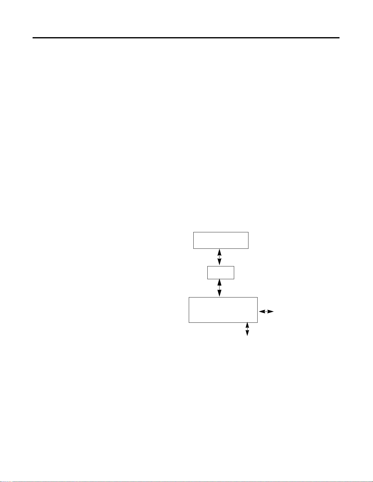
Understanding the 1746 I/O PCI Interface Architecture
PCI bus
Scanner
The 1746 I/O PCI Interface architecture consists of a PCI card that
plugs into a PC and cables to a 1746 I/O chassis. The scanner scans
the 1746 local I/O bus and reads/writes inputs and outputs to/from
the dual port registers.
1747-PCIS
CPU
dual port memory
3DUWLWLRQ %\WHV
UHJLVWHU .
FRPPDQGV YDULDEOH
UHVSRQVH YDULDEOH
RXWSXWLPDJH YDULDEOH
LQSXWLPDJH YDULDEOH
KRVWGDWD YDULDEOH
cable
1747-PCIL
1746 backplane interface
status and user LEDs
3-position switch
user jumper
watchdog contact
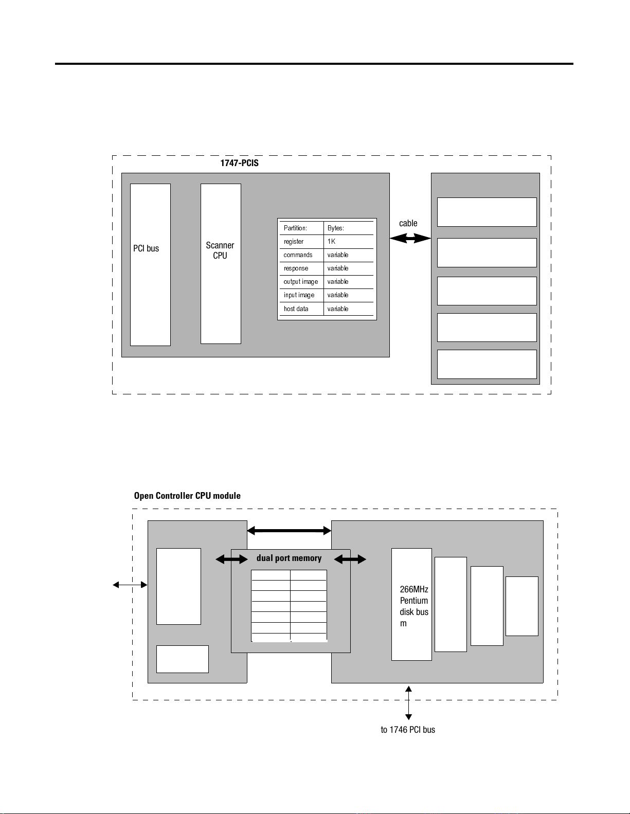
Understanding the Open Controller Architecture
Open Controller CPU module
scanner
80188
to 1746 local
I/O bus
CPU
bus
memory
scanner
firmware
The open controller architecture consists of two CPUs (scanner and
controller) that share dual-port memory. The scanner scans the 1746
local I/O bus and reads/writes inputs and outputs to/from the
dual-port registers. The controller has a PC-based architecture with a
266Mhz Pentium to run your application software.
PCI
dual port memory
Partition: Bytes:
register 1K
commands
responses
output image
input image variable
host data variable
variable
variable
variable
controller (PC-based architecture)
266MHz
Pentium
disk bus
memory
BIOS
OS
application
software
Publication 1747-UM002A-US-P - June 2000
to 1746 PCI bus
Page 17

Overview 1-5
Common Attributes of the 1746 I/O PCI Interface and 1747 Open
Controller Architectures
The functionality described in the rest of this chapter is shared by
both architectures, 1746 I/O PCI Interface and 1747 Open Controller.
The dual port is an 8K byte memory partition (optionally
battery-backed) that provides an interface between the integrated
scanner and your application software that resides on the host.
IMPORTANT
Your application (the code you develop using the API) uses the dual
port memory to communicate with the scanner to handle control
functions on the 1746 backplane, such as:
• scanner commands and responses
• battery and scanner status
• scan rate frequency and timing
• I/O image counters
• priority messages and interrupts
• semaphores to ensure data integrity
• software-generated watchdogs
• control of the 4 user-definable LEDs, the 2-position jumper, and
the 3-position switch
On the 1747-PCIS only, the jumper for the
battery-backup dual-port memory is disabled by
default. You must switch the jumper to enable the
battery-backup feature.
The 1747-OCF dual port is NOT battery-backed.
The scanner functionality of the dual port supports I/O control
functions, such as:
• synchronizing scans to the application
• forcing I/O
• defining discrete-input interrupts
• defining I/O module-driven interrupts (such as for the 1746-BAS
module)
• enabling and disabling I/O slots
• resetting I/O
Publication 1747-UM002A-US-P - June 2000
Page 18

1-6 Overview
In addition to providing access to the control scanner, the dual port
memory also provides non-volatile (optional battery-backed) storage
for:
• I/O values
• application parameters (timers, counters, presets)
Scanner Modes
In both application types, the scanner CPU operates in six
basic modes:
• performing POST (power-on self test)
• waiting for host initialization
• Idle
• Scan
• Faulted
• non-recoverable fault
After the scanner successfully completes the POST, the scanner waits
for an initialization complete command from the application. Once the
scanner receives this command, the scanner enters Idle mode.
Before the scanner can enter Scan mode, the application must
download a valid I/O configuration to the scanner.
If a recoverable fault occurs, the scanner enters Faulted mode. Use the
OC_ClearFault API function to clear the fault before the scanner can
resume operating in Scan mode.
If a non-recoverable fault occurs, reset the scanner (cycle power).
Some possible non-recoverable faults include:
Publication 1747-UM002A-US-P - June 2000
• POST failure
• background diagnostic failure
• internal watchdog timeout
Page 19

Checking LED Indicators
The graphics below show LED displays.
1746 PCI I/O Interface 1747 Open Controller
Overview 1-7
PCI INTERFACE
STATUS BATT
LED 1 LED 2
LED 3 LED 4
OC 266 PENTIUM
STATUS BATT
COM 1 COM 2
LED 1 LED 2
LED 3 LED 4
STATUS
The STATUS indicator reports the status of the scanner. The following
table lists the LED states for STATUS:
This state: Means: Take this action:
Yellow The scanner is running POST. None
Flashing green The scanner is in idle mode and
is not scanning I/O.
Solid green The scanner is scanning I/O. None
None
Flashing red An I/O fault has occurred. Check software to identify
fault condition.
Solid red A scanner internal fault has
occurred.
Power system off and back on.
If the problem persists, service
may be required.
Off The adapter is not powered up. Turn on power.
Publication 1747-UM002A-US-P - June 2000
Page 20

1-8 Overview
Installing the DOS API
Installing the Windows NT API
To install the DOS API, copy the following files to a directory you
create. The sample code files are optional, but they show how to use
the API functions.
This file: Contains:
ocapil.lib API functions that you link to your application
ocapi.h API header file that contains API-referenced structures
sample.c Sample application program calling the API functions
sampleb.mak Sample make file for the Borland C compiler
samplem.mak Sample make file for the Microsoft C compiler
To install the Windows NT API, use the setup utility:
TIP
It is recommended that you exit all applications
before starting the setup process.
1. Copy the contents of the API diskette to a temporary directory
on the open controllerÿs disk drive. (This step is not necessary if
a local diskette drive is connected.) The device driver file is
OCdriver.sys.
2. Select Run from the startup menu, then select the setup.exe
program from the temporary directory.
3. Click on OK to execute the setup utility. Follow the displayed
instructions. Click on Continue.
4. The next dialog lets you choose whether to install the API
executable alone (Runtime) or the API executable and the
development files (Runtime and & Development). To develop
applications with the API, you need the development files. To
only run applications, the development files are not necessary.
The development files consist of an include file, import library,
and sample code.
IMPORTANT
Runtime files may only be installed on a Windows
NT system. However, the development files may be
installed on either Windows NT or Windows 95
systems.
Publication 1747-UM002A-US-P - June 2000
Choose the appropriate installation option and click on Next.
Page 21

Overview 1-9
5. Click on Continue.
6. If the development files were selected in the last dialog, the next
dialog allows a destination directory to be specified. Click on
Continue after you select the directory.
7. The necessary files are copied to the disk, and the system
registry is updated to include the OCdriver information.
8. Press OK to exit the setup utility. The contents of the
temporary directory can now be deleted.
IMPORTANT
You must shutdown and reboot the scanner before
using the API. (The setup utility sets the registry Start
parameter for OCdriver to Automatic; therefore, the
service manager starts the OCdriver when the system
is booted.)
The Windows NT API uses these files:
This file: Contains:
ocapi.lib Import library in Microsoft COFF format
ocapi.h API header file that contains API-referenced structures
ocapi.dll API DLL
sample.c Sample application program calling the API functions
sampleb.mak Sample make file for the Borland C compiler
samplem.mak Sample make file for the Microsoft C compiler
Installation Details
This section describes the actions the setup utility performs to install
the API and OCdriver.
If you select Runtime (Complete), the setup utility:
1. copies the device driver file,
driver directory (
%SystemRoot%\system32\drivers).
OCdriver, to the system device
Publication 1747-UM002A-US-P - June 2000
Page 22

1-10 Overview
2. adds this key and these values to the system registry:
HKEY_LOCAL_MACHINE\SYSTEM\CurrentControlSet\Services
OCdriver
ErrorControl: REG_DWORD 0x1
Group: REG_SZ Extended base
Start: REG_DWORD 0x2
Type: REG_DWORD 0x1
HKEY_LOCAL_MACHINE\SYSTEM\CurrentControlSet\Services
Drivers\ OCdriver
EventMessageFile=
REG_EXPAND_SZ%SystemRoot%\System32\Drivers\OCdriver.sys
TypesSupported= REG_DWORD 0X00000007
3. copies the library file,
OCapi.dll, to the %SystemRoot%\system32
directory.
If you select Runtime & Development, the setup utility performs the
same steps as for Runtime only and the setup utility copies
ocapi.h, and the sample source files to a development directory.
,
ocapi.lib
If you want to develop your application on a computer other than the
open controller, copy the ocapi.lib and ocapi.h files to the
development computer (do not run the setup utility on the
development computer). You won’t be able to run your application
on the development computer. The runtime API only works on an
open controller.
Uninstalling the Windows NT API
To uninstall Windows NT API, use the following instructions.
1. From the Control Panel, select Add/Remove Programs.
2. From the list of installed programs, select Open Control API.
Publication 1747-UM002A-US-P - June 2000
3. Click on Add/Remove.
4. Click on Yes.
All of the API files and registry keys will be deleted.
Page 23

Using the API
Chapter
2
Introduction
Getting Started
This chapter describes the API and how to use its components. For
more information about developing applications using the API, see
chapter 3.
To use the API, make sure you have copied the following files to your
development directories. The sample files are optional.
This file: Contains:
ocapil.lib API functions that you link to your application (DOS only)
ocapi.lib Import library in Microsoft COFF format (Windows NT
only)
ocapi.h API header file that contains API-referenced structures
ocapi.dll API DLL (Windows NT only)
sample.c Sample application program calling the API functions
sampleb.mak Sample MAKE file for the Borland C compiler
samplem.mak Sample MAKE file for the Microsoft C compiler
Your application must link to the appropriate library (
DOS or
copy the sample files and adapt them for your application.
ocapi.lib for Windows NT) and include ocapi.h. You can
ocapil.lib for
1 Publication 1747-UM002A-US-P - June 2000
Page 24

2-2 Using the API
Programming Conventions
This convention: Considerations:
calling convention The DOS API functions are specified using the C programming language syntax. To
header files The API includes a header file (ocapi.h) that contains API function declarations,
sample code The API comes with sample files to provide an example application that communicates
compiler support The DOS API is supplied in the large memory model, compatible with both Microsoft
The API is supplied as an object code library file [DOS (ocapil.lib)]
or a DLL [NT (
ocapi.dll)] that you link with the host application’s
object code using commercially-available tools.
allow you to develop control applications in other programming languages, the API
functions use the standard Pascal calling convention.
The Windows NT API supports any programming languages that use the Win32 _stdcall
calling convention for application interface functions. The Windows NT API function
names are exported from the DLL in undecorated format to simplify access from other
programming languages.
data structure definitions, and other constant definitions. The header file is in standard
C format.
with the scanner. The sample files include all source files and MAKE files required to
build the sample application.
and Borland compilers. The DOS library (ocapil.lib) is compiled as a 16-bit
MS-DOS library using the 80386 instruction set.
The Windows NT library (ocapi.dll) is compiled for use with Microsoft Visual C++
or Borland C++.
DOS Considerations
The DOS API is as consistent as possible with APIs for other operating
system platforms. This makes it easier for you to migrate applications
and it simplifies support. To create a consistent API, careful
consideration was given to these requirements:
This requirement: Considerations:
memory mapping The dual port RAM, or shared memory, is mapped automatically at power-up by the PCI bus in the
host processor’s memory address space on any even 8K boundary between 0xC0000 and 0xDFFFF.
For MS-DOS, it is important that any installed memory managers (such as EMM386) or other TSR
software avoid accessing the 8K dual port memory window.
Place the base memory select jumper in 1M position to allow the PCI BIOS to assign a base
memory address.
DOS interrupts An interrupt is automatically assigned to the scanner by the PCI bus at power-up.
control-break handler Because communication with the scanner requires memory and interrupt resources (as described
above), improper termination of the host application can leave these resources allocated by the
scanner and unusable by other applications. For this reason the API includes a default
control-break handler.
The default control-break handler is installed by OC_OpenScanner. If you press a [Ctrl-C] or
[Ctrl-Break] key sequence, the following prompt is displayed:
Terminate Application? (Y/N) _
A response of Y properly exits the application; a response of N causes the application to continue.
If you need a different control-break handler, you must install it after calling the OC_OpenScanner
function. Always call the OC_CloseScanner function before exiting an application.
Publication 1747-UM002A-US-P - June 2000
Page 25

Windows NT Considerations
During development, the application must be linked with an import
library that provides information about the functions contained within
the DLL. The API import library is compatible with the Microsoft
linker. You can generate import libraries for other programming
languages from the DLL.
The Windows NT API can only be accessed by one process at a time.
The API is designed to be multi-thread safe, so that multi-threaded
control applications can be developed. Where necessary, the API
functions acquire a mutex before accessing the scanner interface. In
this way, access to the scanner device is serialized. If the mutex is in
use by another thread, a thread will be blocked until it is freed.
To create a consistent API, careful consideration was given to these
requirements::
This requirement: Considerations:
Using the API 2-3
memory mapping The NT API device driver detects the Scanner Adapter and automatically configures the
memory window address and interrupt assignment. The base memory address jumper
must be positioned to choose 32 bit addressing. The API and device driver must be
installed on the system.
Place the base memory select jumper in 32-bit position to allow the PCI BIOS to assign a
base memory address anywhere in 32-bit memory for protected-mode applications
(WinNT). NT device drivers (1747-PCINT) use the PCI BIOS or OS services to determine
the memory window base address and provide access to the dual port memory.
• To determine the allocated memory base address and interrupt, run the
Windows NT diagnostic found in Administrative Tools.
NT interrupts An interrupt is automatically assigned to the scanner by the PCI bus at power-up
• To determine the allocated memory base address and interrupt, run the
Windows NT diagnostic found in Administrative Tools.
A group of thread-blocking functions are provided to aid
multi-threaded application development. The functions are:
• OC_WaitForDII
• OC_WaitForEos
• OC_WaitForEosDmdOut
• OC_WaitForIoInt
• OC_WaitForDmdIn
• OC_WaitForExtError
For more information, see chapter 6.
Publication 1747-UM002A-US-P - June 2000
Page 26

2-4 Using the API
Tools to Use
The API functions support both Microsoft and Borland C compilers.
The API disk includes sample MAKE files for each compiler.
When you use the DOS API and link to
ocapil.lib, use the
appropriate command-line switch to select the large memory model.
For more information, see your user manual for your compiler.
If you plan to use a programming language other than C, make sure
the programming language follows the appropriate calling convention
(Pascal for the DOS API; Win32 _stdcall for Windows NT). After you
write your application, use your compiler to link to
(DOS) or
ocapi.lib (Windows NT).
ocapil.lib
The follow pages offer sample MAKE files for DOS and Windows NT
systems on Microsoft and Borland compilers.
Sample DOS MAKE file for Borland compilers
The following sample file shows how to use a Borland MAKE file. The
bold headings indicate the statements you need to modify for your
environment.
#************************************************************************
#
# Title: Makefile for Open Controller API Sample
#
# Abstract:
# This file is used by the Borland MAKE utility to build the
# sample application.
#
# Environment:
# 1747-OCE Open Controller
# MS-DOS
# Borland C/C++ Compiler (16-bit)#
#************************************************************************
#
# Paths to Tools
#
# Note: Modify the following paths to
# correspond to your environment.
#
#---------------------------------------------CPATH = D:\BC5 # Location of Borland tools
CC = $(CPATH)\bin\Bcc # compiler
LINK = $(CPATH)\bin\TLink # linker
MAKE = $(CPATH)\bin\Make # make utility
#---------------------------------------------# Path to API Library and Include file
#
# Note: Modify the following path to
# correspond to your environment.
#
#---------------------------------------------APILIB = ..\ocapil.lib # Path to Open Controller API library
Publication 1747-UM002A-US-P - June 2000
Page 27

APIINC = .. # Path to Open Controller API include file
#---------------------------------------------# Options
#---------------------------------------------CFLAGS = -c -v- -w -ml -I$(APIINC)
LFLAGS = -v- -Tde -d -c
sample.exe : sample.obj $(APILIB) sampleb.mak
$(LINK) $(LFLAGS) c0l sample.obj, $*.exe, $*.map, $(APILIB) cl
clean:
del *.exe
del *.obj
del *.map
rebuild:
$(MAKE) clean
$(MAKE)
.c.obj:
$(CC) $(CFLAGS) $*.c
sample.obj: sample.c $(APIINC)\ocapi.h
sampleb.mak
Using the API 2-5
Sample DOS MAKE file for Microsoft compilers
The following sample file shows how to use a Microsoft MAKE file.
The bold headings indicate the statements you need to modify for
your environment.
#************************************************************************
#
Title: Makefile for Open Controller API Sample
#
# Abstract:
# This file is used by the Microsoft NMake utility to build the
# sample application.
#
# Environment:
# 1747-OCE Open Controller
# MS-DOS
# Microsoft C/C++ Compiler (16-bit)
#************************************************************************
#---------------------------------------------# Note: The environment variables LIB and
# INCLUDE must be set to the path to the
# Microsoft C library and include files.
# For example:
#
# set LIB=D:\MSVC15\LIB
# set INCLUDE=D:\MSVC15\INCLUDE
#
#---------------------------------------------# Paths to Tools
#
# Note: Modify the following paths to
# correspond to your environment.
#
#---------------------------------------------CPATH = D:\MSVC15 # Location of Microsoft tools
CC = $(CPATH)\bin\cl # compiler
LINK = $(CPATH)\bin\link # linker
MAKE = $(CPATH)\bin\nmake # make utility
#---------------------------------------------# Path to API Library and Include file
Publication 1747-UM002A-US-P - June 2000
Page 28

2-6 Using the API
#
# Note: Modify the following path to
# correspond to your environment.
#
#---------------------------------------------APILIB = ..ocapil.lib # Path to Open Controller API library
APIINC = .. # Path to Open Controller API include file
#---------------------------------------------# Options
#------------ -- -- -- -- -- -- -- -- -- -- -- -- -- -- -- -- -CFLAGS = /c /nologo /G3 /W3 /AL /Oi /D /Gx- /I $(APIINC)
LFLAGS = /MAP:A /NOI /PACKC
sample.exe : sample.obj $(APILIB) samplem.mak
$(LINK) $(LFLAGS) sample.obj, $*.exe, $*.map, $(APILIB), nul.def
clean:
del *.exe
del *.obj
del *.map
rebuild:
$(MAKE) -f samplem.mak clean
$(MAKE) -f samplem.mak
.c.obj:
$(CC) $(CFLAGS) $*.c
sample.obj: sample.c $(APIINC)\ocapi.h
samplem.mak
Sample Windows NT MAKE file for Microsoft compilers
The following sample file shows how to use a Microsoft MAKE file.
The bold headings indicate the statements you need to modify for
your environment.
#************************************************************************
# Title: Makefile for Open Controller NT API Sample
#
# Abstract:
# This file is used by the Microsoft NMake utility to build the
# sample application.
#
# Environment:
# 1747-OCE Open Controller
# Microsoft Windows NT 4.0
# Microsoft Visual C++
#
# (c)Copyright Allen-Bradley
#
#************************************************************************
#---------------------------------------------# Note: The environment variable LIB
# must be set to the path to the
# Microsoft C library files.
# For example:
#
# set LIB=D:\MSDEV\LIB
#
#----------------------------------------------
Publication 1747-UM002A-US-P - June 2000
Page 29

Using the API 2-7
# Paths to Tools
#
# Note: Modify the following paths to
# correspond to your environment.
#
#---------------------------------------------CPATH = D:\MSDEV # Location of Microsoft tools
CC = $(CPATH)\bin\cl # compiler
LINK = $(CPATH)\bin\link # linker
MAKE = $(CPATH)\bin\nmake # make utility
#---------------------------------------------# Path to API Library and Include file
#
# Note: Modify the following paths to
# correspond to your environment.
#
#---------------------------------------------APILIB = ..\api\lib\ocapi.lib # Path to Open Controller API library
APIINC = ..\api\include # Path to Open Controller API include file
#---------------------------------# Compiler/Linker Debugging Options
# (Define DEBUG for debugging.)
#---------------------------------!ifdef DEBUG
CDEBUG = -Zi -Od
LDEBUG = -debug:full -debugtype:cv
!else
CDEBUG = -Ox
LDEBUG = /RELEASE
!endif
#------------------------------------------# Compiler Options
#
# -W3 Turn on warnings
# -GB Optimize code for 80486/Pentium
# -MT Use Multithreaded runtime lib
#
#------------------------------------------CFLAGS = -W3 -GB -MT \
-I$(APIINC) -I$(CPATH)\include
#---------------------------------# Linker Options
#
#---------------------------------LFLAGS = /NODEFAULTLIB /SUBSYSTEM:CONSOLE \
/INCREMENTAL:NO /PDB:NONE
#-----------------------------------# Libraries
#
# libcmt Multithreaded C runtime
# kernel32 Base system lib
#
#-----------------------------------LIBS = libcmt.lib kernel32.lib
#--------------------------------# Final target
Publication 1747-UM002A-US-P - June 2000
Page 30

2-8 Using the API
#--------------------------------sample.exe : sample.obj $(APILIB)
$(LINK) @<<
$(LDEBUG) $(LFLAGS) $(LIBS) $**
<<
@echo Finished
clean:
del *.exe
del *.obj
del *.map
rebuild:
$(MAKE) -f samplem.mak clean
$(MAKE) -f samplem.mak
#-------------------------# Intermediate target rules
#-------------------------.c.obj:
$(CC) @<<
/c $(CDEBUG) $(CFLAGS) $*.c
<<
#--------------------------------# Intermediate target dependancies
#---------------------------------
sample.obj: sample.c $(APIINC)\ocapi.h
samplem.mak
Sample Windows NT MAKE file for Borland compilers
The following sample file shows how to use a Borland MAKE file. The
bold headings indicate the statements you need to modify for your
environment.
#************************************************************************
#
# Title: Makefile for Open Controller API Sample
#
# Abstract:
# This file is used by the Borland MAKE utility to build the
# sample application.
#
# Environment:
# 1747-OCE Open Controller
# Microsoft Windows NT 4.0
# Borland C++ Compiler
#
# (c)Copyright Allen-Bradley
#
#************************************************************************
#---------------------------------------------# Paths to Tools
#
# Note: Modify the following paths to
Publication 1747-UM002A-US-P - June 2000
Page 31

Using the API 2-9
# correspond to your environment.
#
#---------------------------------------------CPATH = D:\BC5 # Location of Borland tools
CC = $(CPATH)\bin\Bcc32 # compiler
LINK = $(CPATH)\bin\TLink32 # linker
MAKE = $(CPATH)\bin\Make # make utility
#---------------------------------------------# Path to API Library and Include file
#
# Note: Modify the following path to
# correspond to your environment.
#
#---------------------------------------------APIDLL = ..\api\lib\ocapi.dll # Path to Open Controller API library
APIINC = ..\api\include # Path to Open Controller API include file
APILIB = .\ocapi.lib # Borland compatible import library
#---------------------------------------------# Options
#---------------------------------------------CFLAGS = -c -v -4 -tWM -w -I$(APIINC)
LFLAGS = -v -Tpe -d -c -ap -r
#---------------------------------------------# Final Target
#---------------------------------------------sample.exe : sample.obj $(APILIB) sampleb.mak
$(LINK) @&&|
$(LFLAGS) +
D:\BC5\LIB\c0x32.obj +
$*.obj, $*.exe, $*.map
D:\BC5\LIB\import32.lib +
D:\BC5\LIB\cw32mt.lib +
$(APILIB)
|
clean:
del *.exe
del *.obj
del *.map
del *.lib
rebuild:
$(MAKE) -f sampleb.mak clean
$(MAKE) -f sampleb.mak
.c.obj:
$(CC) $(CFLAGS) $*.c
#---------------------------------------------# Create a Borland-compatible import library
#---------------------------------------------$(APILIB): $(APIDLL)
implib $(APILIB) $(APIDLL)
sample.obj: sample.c $(APIINC)\ocapi.h sampleb.mak
Publication 1747-UM002A-US-P - June 2000
Page 32

2-10 Using the API
Notes:
Publication 1747-UM002A-US-P - June 2000
Page 33

Developing Applications
Chapter
3
Introduction
How the API Functions Are Organized
Programming Sequence
This chapter describes the proper programming sequence for your
application. This chapter also describes how to partition the dual port
memory in the 1746 I/O PCI Interface.
Each of the API functions falls into one of these four categories:
• scanner initialization
• scanner I/O configuration
• data input/output
• user interface/miscellaneous
Chapter 6 describes each API function and identifies its functionality
group.
Follow this programming sequence when you develop your
application.
1
Access the scanner
2
2
Initialize the scanner
Initialize the scanner
3
Configure the scanner
4
Control scanner
operation
5
Scan I/O
1 Publication 1747-UM002A-US-P - June 2000
Page 34

3-2 Developing Applications
Access the scanner
The host application must first call OC_OpenScanner to gain access to
the scanner. Once an application has access, no other application can
gain access to the scanner. When the application no longer requires
access to the scanner, it must call OC_CloseScanner to release access
of the scanner to other applications.
Once the scanner is opened, you must call OC_CloseScanner before
exiting the application.
Initialize the scanner
After the scanner is reset and performs its POST, the scanner waits for
initialization. In this state, the scanner can’t be configured or control I/
O. The only operational function is that which controls the LEDs. Any
call to a function that requires the scanner to be initialized returns an
error. You must initialize the scanner by sending it partitioning
information before the host application can communicate with the
scanner.
Initialize the scanner by calling the OC_InitScanner function to send
the scanner partitioning information, which defines in bytes the size of
the output image, the input image, and the host retentive data. Each
of these memory segments must be at least large enough to hold their
respective data, and must be an even number. If the input or output
partition is initialized smaller than the actual size of the input or
output image for a configuration, the OC_DownloadIOConfiguration
function returns an error. The host retentive data size is optional and
can be 0.
To determine the input image and output image sizes, use the
OC_CreateIOConfiguration function to create an I/O configuration.
OC_CreateIOConfiguration returns an I/O configuration with the
number of bytes of inputs and outputs for each module. If a
configuration already exists, you can use OC_GetIOConfig to return
the current I/O configuration. The application can then calculate the
minimum size of the segments required to hold the input and output
images. For more information, see page 3-18.
Publication 1747-UM002A-US-P - June 2000
Page 35

Developing Applications 3-3
The API has a defined constant specifying the total number of bytes
available for the three segmenters This constant is specified as:
OCSEGMENTSIZELIMIT
Once the scanner has been initialized properly it cannot be
re-initialized unless it is reset with the OC_ResetScanner function.
Once the scanner is reset, scanner communications are disabled again
until the scanner is initialized. The host application can call
OC_GetScannerStatus to determine if the scanner has been initialized.
If the scanner was previously initialized, the host application can
retrieve the initialization partition information with the
OC_GetScannerInitInfo function instead of resetting and re-initializing
the scanner.
Configure the scanner
To access I/O modules in a rack, you must define the rack sizes and
installed module types for the scanner. You can either create a specific
configuration or read the current configuration. The scanner cannot
be set to Scan mode until it has been configured (received a valid
scanner configuration).
If the scanner is in Scan mode and the host application has not
downloaded a scanner configuration, the scanner has already been
configured. To control I/O, use OC_GetIOConfiguration to retrieve
the current scanner configuration.
The application can read the current I/O configuration with the
OC_GetIOConfiguration function. If the scanner is not in Scan mode,
this function returns the current scanner configuration which can be
downloaded to the scanner using OC_DownloadIOConfiguration.
If the application requires a specific I/O configuration, the application
can define the I/O configuration structure with the rack sizes and
module types installed in each slot. The application passes this
configuration structure to OC_CreateIOConfiguration.
OC_CreateIOConfiguration returns a scanner configuration that can be
downloaded to the scanner. For more information, see chapter 5.
Once a valid scanner configuration is successfully downloaded to the
scanner via OC_DownloadIOConfiguration, the application can set the
scanner to Scan mode and control I/O.
Both OC_CreateIOConfiguration and OC_GetIOConfiguration build
the configuration data from an internal database of supported I/O
modules.
Publication 1747-UM002A-US-P - June 2000
Page 36

3-4 Developing Applications
Control scanner operation
Once the scanner has been configured, the application can control
scanner operation. The host application can:
• set the scanner to Idle or Scan mode
• control the scan time
• control I/O
• read or write module files
• clear faults
• enable/disable slots
• set I/O Idle state
• install/remove forces
• handle module interrupts and discrete input interrupts
The API uses messages to communicate with the scanner. The scan
time settings affect the time allowed by the scanner to process a
message. OC_SetScanTime adjusts the scan time of the application.
The scanner processes messages during any available time that it is
not scanning I/O. If the scan time is set too small, some API functions
might take a relatively long time to complete. If some functions seem
to be taking too long to complete, increase the scan time to provide
more time for the scanner to process messages. If the scan time is set
too large, I/O won’t update fast enough.
From the end of post until entering scan mode, the scanner holds the
I/O reset line high.
For information about estimating scan time, see PCIS Bus Card for
1746 Local I/O Installation Instructions, publication 1747-5.31.
Scan I/O
The scanner provides two basic methods for scanning I/O: timed
scans and on-demand scans. The host application can use either, or a
combination of both.
Typically, the scanner reads inputs from modules and writes outputs
to modules once every scan time. To read inputs and write outputs,
the application calls OC_ReadInputImage and OC_WriteOutputImage
independently from the scanner’s scan sequence.
Publication 1747-UM002A-US-P - June 2000
Page 37

Developing Applications 3-5
The application can change the behavior of the input and output
scans by allowing the application to have more control over I/O
scanning. The application can prevent the scanner from doing any
output scans and allow the application to read inputs and initialize
outputs before the scanner begins to write outputs. This mode allows
the application to pre-scan the inputs before the outputs are written.
The application can set the scanner to a conditional scan mode where
the scanner writes outputs at the next scan time after the application
writes data to the output image. In this mode, the scanner only writes
outputs each time the application writes data to the output image.
The application can also prevent output scans by the scanner and
have the scanner send a message after every input scan. The
application can detect an end-of-scan message and then read the
input image, perform logic, and write outputs using
OC_DemandOutputScan to force the scanner to write outputs
immediately. This lets the application synchronize its control loop
with the input and output scans.
The application can also disable both input and output scans. In this
mode, the scanner is a slave and input or output scans only take place
when requested by the host application.
Programming Example
The following DOS example (sample.c on your API disk) shows
how to program the above steps. Callouts on the right margin identify
for DOS
/************************************************************************
*
* FILE: sample.c
*
* PURPOSE:Sample application code for 1746 I/O PCI Interface API
*
* SUMMARY:This program,
* - Resets and initializes the scanner.
* - Displays the scanner firmware and hardware versions.
* - Autconfigures the I/O in chassis.
* - Reads the front panel switch position and lights LED 1.
* - Reads first discrete input module data word.
* - Writes incremental data to first output module data word.
* - Closes connection to scanner and exits.
*
* ENVIRONMENT: 1747-PCIS 1746 I/O PCI Interface
* MS-DOS
* Borland/Microsoft C/C++ Compiler (16-bit)
*
************************************************************************/
the code for each step.
Publication 1747-UM002A-US-P - June 2000
Page 38

3-6 Developing Applications
/*=======================================================================
= INCLUDE FILES =
=========================================================================*/
#include ”ocapi.h”
#include <stdio.h>
#include <dos.h>
#include <time.h>
#include <conio.h>
#include <string.h>
/*=======================================================================
= MODULE WIDE GLOBAL VARIABLES =
=========================================================================*/
HANDLE Handle; /* Software ID to scanner device */
OCIOCFG OCcfg; /* Chassis I/O config. data structure */
/*=======================================================================
= FUNCTION PROTOTYPES =
=========================================================================*/
void Ioexit( int );
/*=======================================================================
= MAIN PROGRAM =
=========================================================================*/
void main()
{
int retcode; /* Return code from API calls */
int i;
int slots;
int input_slot, input_found = 0;
int output_slot, output_found = 0;
OCINIT ocpart;
BYTE status;
OCVERSIONINFO verinfo;
BYTE swpos;
WORD wData;
/*
** Open the scanner
*/
retcode = OC_OpenScanner( &Handle, 0, 0);
if ( retcode != SUCCESS )
{
printf( ”\nERROR: OC_OpenScanner failed: %d\n”, retcode );
Ioexit( 1 );
}
Access the
scanner.
Publication 1747-UM002A-US-P - June 2000
Page 39

Developing Applications 3-7
/*
** Reset the scanner
*/
printf( ”\n\n Going to reset OC, takes 6 seconds to complete...\n” );
table
retcode = OC_ResetScanner( Handle, OCWAIT );
if ( retcode != SUCCESS )
{
printf( ”\nERROR: OC_ResetScanner failed: %d\n”, retcode );
Ioexit( 1 );
}
/*
** Check scanner status register
*/
retcode = OC_GetScannerStatus( Handle, &status );
if ( retcode != SUCCESS )
{
printf( ”\nERROR: OC_GetScannerStatus failed: %d\n”, retcode );
Ioexit( 1 );
}
if ( status != SCANSTS_INIT)
{
printf(”\nERROR: POST failure detected: %d\n”, status);
Ioexit(1);
}
/*
** Initialize the DPR partitions
** You can use OC_CreateIOConfiguration to determine the I/O image
** sizes before paritioning the DPR
*/
ocpart.OutputImageSize = 0x800;
ocpart.InputImageSize = 0x800;
ocpart.HostRetentiveDataSize = 0;
retcode = OC_InitScanner( Handle, &ocpart );
if ( retcode != SUCCESS )
{
printf(” \nERROR: OC_InitScanner failed: %d\n”, retcode );
Ioexit( 1 );
}
/*
** Display software/hardware versions
*/
retcode = OC_GetVersionInfo( Handle, &verinfo );
if ( retcode != SUCCESS )
{
printf( ”\nERROR: OC_GetVersionInfo failed: %d\n”, retcode );
Ioexit( 1 );
}
printf( ”\n\n Scanner Firmware Series: %02d Revision: %02d ”,
verinfo.ScannerFirmwareSeries, verinfo.ScannerFirmwareRevision );
printf( ”\n Hardware Series: %02d Revision: %02d”,
verinfo.OCHardwareSeries, verinfo.OCHardwareRevision );
delay( 3000 );
/*
** Read switch position
*/
retcode = OC_GetSwitchPosition( Handle, &swpos );
if ( retcode != SUCCESS )
{
printf( ”\nERROR: OC_GetSwitchPosition failed: %d\n”, retcode );
Ioexit( 1 );
Initialize the
scanner
Publication 1747-UM002A-US-P - June 2000
Page 40

3-8 Developing Applications
}
printf( ”\n\n Switch position: ” );
switch( swpos )
{
case SWITCH_TOP:
case SWITCH_BOTTOM:
case SWITCH_MIDDLE:
}
delay( 3000 );
/*
** Read auto-config
*/
retcode = OC_GetIOConfiguration( Handle, &OCcfg );
if ( retcode != SUCCESS )
{
printf( ”\nERROR: OC_GetIOConfiguration failed: %d\n”, retcode );
Ioexit( 1 );
}
/*
** Display rack configuration
*/
slots = OCcfg.Rack1Size + OCcfg.Rack2Size + OCcfg.Rack3Size;
if ( slots > 31 )
slots = 31;
printf( ”\n\n Chassis configuration ” );
for ( i=1; i < slots; i++ )
{
if ( OCcfg.SlotCfg[i].type != 0xff )
else
/* Find digital input card */
if ( OCcfg.SlotCfg[i].mix < 8 && !input_found )
{
}
/* Find digital output card */
if ( (OCcfg.SlotCfg[i].mix > 7) && (OCcfg.SlotCfg[i].mix < 32) && !output_found
)
{
}
}
delay( 3000 );
printf( ”Top \n” );
break;
printf( ”Bottom \n” );
break;
printf( ”Middle \n” );
break;
printf( ”\n Slot %2d: Type %2d, Mix %3d %s”,
i, OCcfg.SlotCfg[i].type, OCcfg.SlotCfg[i].mix,
OCcfg.SlotCfg[i].Name );
printf( ”\n Slot %2d: %s”, i, OCcfg.SlotCfg[i].Name );
input_found = 1;
input_slot = i;
output_found = 1;
output_slot = i;
Publication 1747-UM002A-US-P - June 2000
Page 41

/*
** Download the configuration to the scanner
*/
retcode = OC_DownloadIOConfiguration( Handle, &OCcfg );
if ( retcode != SUCCESS )
{
retcode );
}
/*
** Set output update mode to always
*/
retcode = OC_SetOutputUpdateMode( Handle, OUTUPD_ALWAYS );
if ( retcode != SUCCESS )
{
retcode );
}
/*
** Set scan time to 5ms, periodic scan mode
*/
retcode = OC_SetScanTime( Handle, SCAN_PERIODIC, 20 );
if ( retcode != SUCCESS )
{
}
/*
** Goto Scan Mode
*/
retcode = OC_SetScanMode( Handle, SCAN_RUN );
if ( retcode != SUCCESS )
{
}
/*
** Turn on User LED 1
*/
retcode = OC_SetUserLEDState( Handle, 1, LED_GREEN_SOLID );
if ( retcode != SUCCESS )
{
}
printf( ”\n\n LED1 is on solid green now. \n” );
delay( 3000 );
Developing Applications 3-9
printf( ”\nERROR: OC_DownloadIOConfiguration failed: %d\n”,
Ioexit( 1 );
printf( ”\nERROR: OC_SetOutputUpdateMode failed: %d\n”,
Ioexit( 1 );
printf( ”\nERROR: OC_SetScanTime failed: %d\n”, retcode );
Ioexit( 1 );
printf( ”\nERROR: OC_SetScanMode failed: %d\n”, retcode );
Ioexit( 1 );
printf( ”\nERROR: OC_SetUserLEDState failed: %d\n”, retcode );
Ioexit( 1 );
Configure
the
scanner.
Control scanner
operation
Publication 1747-UM002A-US-P - June 2000
Page 42

3-10 Developing Applications
/*
** Read first Input word
*/
retcode = OC_ReadInputImage( Handle, NULL, input_slot, 0, 1, &wData );
if ( retcode != SUCCESS )
{
printf( ”\nERROR: OC_ReadInputImage failed: %d\n”, retcode );
Ioexit( 1 );
}
printf( ”\n\n First input image data word --> 0x%04x \n”, wData );
delay( 3000 );
/*
** Write to the first Output word
*/
printf( ”\n\n Incrementing first discrete output word. \n” );
for ( wData=0; wData < 256; wData++)
{
retcode = OC_WriteOutputImage( Handle, NULL, output_slot, 0, 1,
&wData );
if ( retcode != SUCCESS )
{
printf(”\nERROR: OC_WriteOutputImage failed: %d\n”,
retcode);
Ioexit(1);
}
delay ( 10 );
}
/*
** Must always close the scanner before exiting
*/
OC_CloseScanner( Handle );
printf( ”\n\n Program is done! \n\n” );
} /* end main() */
/************************************************************************
*
* Name: Ioexit
*
* Description:
*
* Common error handling routine. This routine displays any
* extended error and exits the program.
*
* Arguments:
* retcode : int ( input )
* This error code is passed to the exit() routine.
*
* External effects:
* The program is terminated.
*
* Return value:
* none
*
************************************************************************/
void Ioexit( int retcode )
{
OCEXTERR exterr;
char *msg;
if (OC_GetExtendedError(Handle, &exterr) == SUCCESS)
{
if ( exterr.ErrorCode != 0 )
{
Scan I/O
Publication 1747-UM002A-US-P - June 2000
Page 43

OC_ExtendedErrorMsg(Handle, &exterr, &msg);
printf(”\nERROR: %s\n”, msg);
}
}
OC_CloseScanner(Handle);
exit(retcode);
} /* end Ioexit() */
Developing Applications 3-11
Programming Example for
The following Windows NT example (sample.c on your Windows
NT API disk) shows how to program the above steps. Callouts on the
Windows NT
/********************************************************************
* Title: Simple application sample code for 1746 I/O PCI Interface API
*
* Abstract:
*
* This file contains a simple application using the PCI
* bus interface API.
*
* Environment:
* 1747-PCIS 1746 I/O PCI Interface
* Microsoft Windows NT 4.0
* Microsoft Visual C++ / Borland C++
* (c)Copyright Allen-Bradley *
************************************************************************/
/*=======================================================================
= INCLUDE FILES =
=======================================================================*/
#include <windows.h>
#include <process.h>
#include <stdio.h>
#include <stdlib.h>
#include <time.h>
#include <conio.h>
#include <string.h>
#include "ocapi.h"
/*=======================================================================
= MODULE WIDE GLOBAL VARIABLES =
=======================================================================*/
HANDLE OChandle;
OCIOCFG OCcfg;
/************************************************************************
* Entry point:
* Ioexit
*
* Description:
* Common error handling routine. This routine displays any
* extended error and exits the program.
*
* Arguments:
* rc : int ( input )
* This error code is passed to the exit() routine.
right margin identify the code for each step.
Publication 1747-UM002A-US-P - June 2000
Page 44

3-12 Developing Applications
*
* External effects:
* The program is terminated.
*
* Return value:
* none
*
* Access: Public
* ----------------------------------------------------------------------* Notes:
*
*************************************************************************/
void Ioexit
int rc
) {
OCEXTERR exterr;
char *msg;
if (OC_GetExtendedError(OChandle, &exterr) == SUCCESS)
{
if ( exterr.ErrorCode != 0 )
{
OC_ExtendedErrorMsg(OChandle, &exterr, &msg);
printf("\n\nERROR: %d %s\n", msg, exterr.ErrorCode);
}
}
OC_CloseScanner(OChandle);
exit(rc);
} /* end Ioexit() */
/*************************************************************************
* Entry point:
* tErrorEvent
*
* Description:
* Thread to handle errors.
*
* Arguments:
* none
*
* External effects:
* none
*
* Return value:
* none
*
* Access: Public
*
*----------------------------------------------------------------------* Notes:
*
************************************************************************/
void tErrorEvent( void *dummy )
{
while(1)
{
/* Sleep until the scanner reports an error */
OC_WaitForExtError(OChandle, INFINITE);
/* An error has occurred. Perform whatever error handling */
/* that is necessary. In this case, we just print a message */
/* and exit the process. */
Ioexit(1);
}
} /* end tErrorEvent() */
Publication 1747-UM002A-US-P - June 2000
Page 45

Developing Applications 3-13
/************************************************************************ *
* Entry point:
* main
*
* Description:
* Entry point of the PCI I/O bus interface API sample application.
*
* This program resets, initializes, and autoconfigures the scanner.
* It displays the scanner firmware and hardware versions, and
* the front panel switch position.
* It lights User LED 1, reads inputs from a 32 pt discrete
* input module, and writes data to the M0 file on a BAS module.
*
* Arguments:
* none
*
* External effects:
* none
*
* Return value:
* 0 if no errors were encountered
* 1 if errors
*
* Access: Public
*
*----------------------------------------------------------------------* Notes:
*
************************************************************************/
main()
{
int rc;
int i;
int slots;
int BASslot;
int IB32slot;
int fRecreateIOcfg;
OCINIT ocpart;
BYTE status;
OCVERSIONINFO verinfo;
BYTE swpos;
WORD wData,wLen;
BYTE temp;
BASslot = IB32slot = 0;
fRecreateIOcfg = 0;
/* Open the scanner */
if (SUCCESS != (rc = OC_OpenScanner(&OChandle)))
{
Access the
scanner.
printf("\nERROR: OC_OpenScanner failed: %d\n", rc);
Ioexit(1);
}
/* Create an error-handling thread */
if (-1 == (long) _beginthread(tErrorEvent, 0, NULL))
printf("\nERROR: _beginthread tErrorEvent failed.\n");
Publication 1747-UM002A-US-P - June 2000
Page 46

3-14 Developing Applications
/* Reset the scanner */
printf("\nResetting the scanner...");
if (SUCCESS != (rc = OC_ResetScanner(OChandle, OCWAIT)))
{
printf("\nERROR: OC_ResetScanner failed: %d\n", rc);
Ioexit(1);
}
/* Check scanner status register */
if (SUCCESS != (rc = OC_GetScannerStatus(OChandle, &status)))
{
printf("\nERROR: OC_GetScannerStatus failed: %d\n", rc);
Ioexit(1);
}
if ( status != SCANSTS_INIT)
{
printf("\nERROR: POST failure detected: %d\n", status);
Ioexit(1);
}
/* Initialize the DPR partitions */
ocpart.OutputImageSize = 0x800;
ocpart.InputImageSize = 0x800;
ocpart.HostRetentiveDataSize = 0;
if (SUCCESS != (rc = OC_InitScanner(OChandle, &ocpart)))
{
printf("\nERROR: OC_InitScanner failed: %d\n", rc);
Ioexit(1);
}
/* Display software/hardware versions */
if (SUCCESS != (rc = OC_GetVersionInfo(OChandle, &verinfo)))
{
printf("\nERROR: OC_GetVersionInfo failed: %d\n", rc);
Ioexit(1);
}
printf("\nOC API Series: %02d Revision: %02d ",
verinfo.APISeries,verinfo.APIRevision);
printf("\nOCdriver Series: %02d Revision: %02d ",
verinfo.OCdriverSeries, verinfo.OCdriverRevision);
printf("\nOC Scanner Firmware Series: %02d Revision: %02d ",
verinfo.ScannerFirmwareSeries, verinfo.ScannerFirmwareRevision);
printf("\nOC Hardware Series: %02d Revision: %02d\n",
verinfo.OCHardwareSeries, verinfo.OCHardwareRevision);
/* Read switch position */
if (SUCCESS != (rc = OC_GetSwitchPosition(OChandle, &swpos)))
{
printf("\nERROR: OC_GetSwitchPosition failed: %d\n", rc);
Ioexit(1);
}
printf("\nSwitch position: ");
switch(swpos)
{
case SWITCH_TOP:
printf("Top");
break;
case SWITCH_BOTTOM:
printf("Bottom");
break;
case SWITCH_MIDDLE:
printf("Middle");
break; }
/* Read temperature */
if (SUCCESS != (rc = OC_GetTemperature(OChandle, &temp)))
{
Initialize the
scanner
Publication 1747-UM002A-US-P - June 2000
Page 47

Developing Applications 3-15
printf("\nERROR: OC_GetTemperature failed: %d\n", rc);
Ioexit(1);
}
printf("\nTemperature: %dC ", temp);
/* Read auto-config */
if (SUCCESS != (rc = OC_GetIOConfiguration(OChandle, &OCcfg)))
{
printf("\nERROR: OC_GetIOConfiguration failed: %d\n", rc);
Ioexit(1);
}
/* Display rack configuration */
slots = OCcfg.Rack1Size + OCcfg.Rack2Size + OCcfg.Rack3Size;
if ( slots > 31 ) slots = 31;
printf("\n\nRack configuration:");
for (i=1; i<slots; i++)
{
if (OCcfg.SlotCfg[i].type != 0xff)
{
printf("\nSlot %2d: Type %2d, Mix %3d %s",
i, OCcfg.SlotCfg[i].type, OCcfg.SlotCfg[i].mix,
OCcfg.SlotCfg[i].Name);
}
else
{
printf("\nSlot %2d: %s", i, OCcfg.SlotCfg[i].Name);
}
/* check for BAS modules class 1 or 4 */
if ( ((OCcfg.SlotCfg[i].mix == 35) || (OCcfg.SlotCfg[i].mix == 131))
&& (OCcfg.SlotCfg[i].type == 6))
{
if ( OCcfg.SlotCfg[i].mix == 35 )
{ /* if Class 1 BAS module, then ...
OCcfg.SlotCfg[i].mix = 131; /* ...make it class 4 */
OCcfg.SlotCfg[i].Name = NULL; /* remove name so that OC_CreateIOConfiguration
will key off mix/type */
fRecreateIOcfg = 1;
}
BASslot = i;
}
/* check for IB32 modules */
if ( OCcfg.SlotCfg[i].mix == 7 )
{
IB32slot = i;
}
}
/* if we converted a Class 1 BAS module to Class 4, recreate the IO configuration */
/* to insure we get the M0 and M1 file sizes */
if (fRecreateIOcfg == 1)
{
if (SUCCESS != (rc = OC_CreateIOConfiguration(&OCcfg)))
{
printf("\nERROR: OC_CreateIOConfiguration failed: %d\n", rc);
Ioexit(1);
}
}
Publication 1747-UM002A-US-P - June 2000
Page 48

3-16 Developing Applications
/* Download the configuration to the scanner */
if (SUCCESS != (rc = OC_DownloadIOConfiguration(OChandle, &OCcfg)))
{
printf("\nERROR: OC_DownloadIOConfiguration failed: %d\n", rc);
Ioexit(1);
}
/* Set output update mode to always */
if (SUCCESS != (rc = OC_SetOutputUpdateMode(OChandle, OUTUPD_ALWAYS)))
{
printf("\nERROR: OC_SetOutputUpdateMode failed: %d\n", rc);
Ioexit(1);
}
/* Set scan time to 5ms, periodic scan mode */
if (SUCCESS != (rc = OC_SetScanTime(OChandle, SCAN_PERIODIC, 20)))
{
printf("\nERROR: OC_SetScanTime failed: %d\n", rc);
Ioexit(1);
}
/* Goto Scan Mode */
if (SUCCESS != (rc = OC_SetScanMode(OChandle, SCAN_RUN)))
{
printf("\nERROR: OC_SetScanMode failed: %d\n", rc);
Ioexit(1);
}
/* Turn on User LED 1 */
if (SUCCESS != (rc = OC_SetUserLEDState(OChandle, 1, LED_GREEN_SOLID)))
{
printf("\nERROR: OC_SetUserLEDState failed: %d\n", rc);
Ioexit(1);
}
/* Read word 0 of IB32 module */
if ( IB32slot != 0 )
{ if (SUCCESS != (rc = OC_Rea dInputImage(OChandle, NULL , IB32slot, 0,
1, &wData)))
{
printf("\nERROR: OC_ReadInputImage failed: %d\n", rc);
Ioexit(1);
} }
/* Write the data read to word 2 of BAS module M0 file */
wLen = 1; if ( BASslot != 0 )
{
if (SUCCESS != (rc = OC_WriteModuleFile(OChandle, FILTYP_M0, &wData,
BASslot, 2, wLen)))
{
printf("\nERROR: OC_WriteModuleFile failed: %d\n", rc);
Ioexit(1);
}
}
/* Close the scanner before exiting */
OC_CloseScanner(OChandle);
return(0);
} /* end main()*/
Configure the
scanner.
Control scanner
operation.
Scan I/O
Publication 1747-UM002A-US-P - June 2000
Page 49

Developing Applications 3-17
Handling Interrupt Messages
Handling Errors
Modules that communicate via discrete input interrupts or module
interrupts require special attention. The API buffers these interrupts
internally until they are extracted via OC_PollScanner. The internal
message buffer can hold as many as 5 messages. If the message buffer
is full, the oldest message in the buffer is overwritten by the next
message. Interrupts will be missed if OC_PollScanner is not called by
the application more often than interrupts are received.
For Windows NT, use the OC_WaitForxxx functions.
Every function call returns a status code for the function. Check this
status code before using the data returned by the function. The
scanner reports faults and other errors via messages. The API library
buffers these errors internally and reports their existence as an
Extended Error. The application must periodically call
OC_GetExtendedError to determine if an extended error message
exists.
The library buffers extended errors in a queue. The queue can hold as
many as 5 extended errors at one time. If the queue is full when a
new extended error is received from the scanner, the oldest extended
error is lost and ERR_OCOVERRUN is returned. The host application
must call OC_GetExtendedError periodically to remove existing
extended errors from the buffer.
Extended Errors cause the scanner to fault. Once the scanner is
faulted, it is forced to Idle mode and cannot go to Scan mode until the
Extended Errors are extracted via OC_GetExtendedError and the fault
is cleared via OC_ClearFault. For Windows NT, use the
OC_WaitForExtError function.
Publication 1747-UM002A-US-P - June 2000
Page 50

3-18 Developing Applications
Determining Partition Sizes for Shared Memory
typedef struct tagOCINIT {
WORD OutputImageSize; /* size in bytes */
WORD InputImageSize; /* size in bytes */
WORD HostRetentiveDataSize; /* size in bytes */
} OCINIT;
The host application initializes the scanner by providing partitioning
information, which contains the size of memory to be reserved in the
shared memory for the input and output images. The size of memory
to be reserved for each of the images must be greater than or equal to
the number of input and output words required by each module. The
host application can’t communicate with the scanner until it has been
initialized.
The partitioning information is passed to OC_InitScanner in the
OCINIT structure, which is defined as:
To determine the input and output image sizes, call
OC_CreateIOConfiguration with a configuration that contains the I/O
modules to be installed. OC_CreateIOConfiguration returns the
number of bytes of I/O required by each module. Or you can use
OC_GetIOConfig to use the current configuration, if one exists. The
input and output sizes are based on the number of words of I/O
required by each module. As an estimate, take the total number of
input and output words for all the modules in the system and multiply
by two to get the number of required bytes. The following code
fragment calculates the number of bytes required by the input and
output images:
OCINIT initinfo;
OCIOCFG iocfg;
int i,numslots;
/* assuming application has filled iocfg with I/O configuration */
OC_CreateIOConfiguration(&iocfg);
numslots = iocfg.Rack1Size + iocfg.Rack2Size + iocfg.Rack3Size;
if ( numslots > 31 ) numslots = 31;
initinfo.OutputImageSize = initinfo.InputImageSize = 0;
for ( i=1 ; i<numslots ; i++) {
initinfo.OutputImageSize += ((iocfg.SlotCfg[i].OutputSize+1) / 2) * 2;
initinfo.InputImageSize += ((iocfg.SlotCfg[i].InputSize+1) / 2) * 2;
}
Publication 1747-UM002A-US-P - June 2000
Page 51

Any remaining shared memory can be allocated for host retentive
data, which is the portion of the dual port RAM that you can use to
store data in case power fails. If the application doesn’t need host
retentive data, set its size to 0. If the application needs host retentive
data, the application can determine the amount of memory available
by using the OCSEGMENTSIZELIMIT constant.
This constant specifies the total number of bytes available for the
three segment sizes. To calculate the maximum memory available for
the host retentive data, use this formula:
initinfo.HostRetentiveDataSize =
OCSEGMENTSIZELIMIt - initinfo.OutputImageSize - initinfo.InputImageSize;
If the I/O configuration changes and causes the image sizes to
change, the maximum memory available for Host Retentive Data will
change accordingly, and information stored in the Host Retentive Data
memory may be overwritten.
Developing Applications 3-19
Publication 1747-UM002A-US-P - June 2000
Page 52

3-20 Developing Applications
Notes:
Publication 1747-UM002A-US-P - June 2000
Page 53

Using the API Structures
Chapter
4
Introduction
API Structures
Structure Name: Syntax:
DII_CFG
Passed to OC_ConfigureDII.
Configures a discrete input
interrupt for a module.
FORCEDATA
Passed to OC_SetForces.
Configures input and output
forces.
MSGBUF
Returned by OC_PollScanner.
MsgID identifies the
message type. Type-specific
data is contained in
MsgData[ ].
OCEXTERR
Returned by
OC_GetExtendedError. I/O
error report from scanner.
This chapter describes the structures the API uses. These structures are
declared in
ocapi.h.
The table below list API structures.
typedef struct tagDII_CFG
BYTE SlotNum; /* slot number */
BYTE IOIncludeMask; /* declare which Discrete Inputs can cause interrupts */
BYTE IOEdgeType; /* select required transition of each discrete input */
WORD PresetCount; /* set the number of transitions required to cause interrupt */
} DII_CFG;
typedef struct tagFORCEDATA
{
BYTE SlotNum; /* slot number */
WORD WordOffset; /* offset to word to force */
BYTE IOType; /* selects force inputs or outputs */
WORD ForceMask; /* bits set to 1 are forced, 0 removes forces */
WORD ForceVal; /* selects force state of bits set to 1 in ForceMask */
} FORCEDATA;
#define OCMSGDATASIZE4 /* number of bytes of message data */
typedef struct tagMSGBUF
{
BYTE MsgID; /* Message type */
BYTE MsgData[OCMSGDATASIZE];/* Type-specific data */
} MSGBUF;
#define OCERRDATASIZE3 /* number of bytes of error data */
typedef struct tagOCEXTERR
{
BYTE ErrorCode; /* Extended error code */
BYTE SlotNum; /* Associated slot number */
BYTE ErrorData[OCERRDATASIZE];/* Error code data */
} OCEXTERR;
OCINIT
Passed to OC_InitScanner
function to specify dual port
RAM partition sizes for
output image, input image,
and host retentive data.
1 Publication 1747-UM002A-US-P - June 2000
typedef struct tagOCINIT
{
WORD OutputImageSize; /* size in bytes */
WORD InputImageSize; /* size in bytes */
WORD HostRetentiveDataSize;/* size in bytes */
} OCINIT;
Page 54

4-2 Using the API Structures
Structure Name: Syntax:
OCIOCFG
Used by
OC_CreateIOConfiguration,
OC_GetIOConfiguration, and
OC_DownloadIOConfiguratio
n. Configuration information
for a system. 1, 2, or 3 racks
may be configured for up to
30 I/O modules. (Slot 0 is
reserved for the 1746 I/O PCI
Interface.)
typedef struct tagOCIOCFG
{
BYTE Rack1Size;/* number of slots in Rack 1 */
BYTE Rack2Size;/* number of slots in Rack 2 */
BYTE Rack3Size;/* number of slots in Rack 3 */
OCSLOTCFGSlotCfg[OCMAXSLOT];/* configuration for each slot */
} OCIOCFG;
OCSLOTCFG
Configuration information for
a module. The mix and type
codes together form a unique
identification for each
module.
OCVERSIONINFO
Returned by
OC_GetVersionInfo. Software
and hardware version
numbers.
STSFILE
Scanner status file.
typedef struct tagOCSLOTCFG
{
BYTE mix; /* mix code */
BYTE type; /* type code */
BYTE InputSize; /* number of inputs in bytes */
BYTE OutputSize; /* number of outputs in bytes */
WORD M0Size; /* size of M0 file in words */
WORD M1Size; /* size of M1 file in words */
WORD GSize; /* size of G file in words */
WORD *GData; /* pointer to array of length GSize words */
char *Name; /* pointer to module name string */
} OCSLOTCFG;
typedef struct tagOCVERSIONINFO
{
WORD APISeries; /* API series */
WORD APIRevision; /* API revision */
WORD ScannerFirmwareSeries;/* Scanner firmware series */
WORD ScannerFirmwareRevision;/* Scanner firmware revision */
WORD OCHardwareSeries; /* Hardware series */
WORD OCHardwareRevision;/* Hardware revision */
WORD OCdriverSeries /* OCdriver series - Windows NT only */
WORD OCdriverRevision /* Ocdriver reviwion - Windows NT only */
} OCVERSIONINFO;
typedef struct tagSTSFILE
{
WORD wWordNum[OCSTSFILEWSIZE];
} STSFILE;
Publication 1747-UM002A-US-P - June 2000
Page 55

Configuring I/O Modules
Chapter
5
Introduction
Configuring I/O
This chapter explains how to configure the I/O modules for your 1746
I/O PCI Interface system. You can either use the autoconfigure
(OC_GetIOConfiguration) function or build your own configuration
(OC_CreateIOConfiguration).
A separate I/O configuration utility is available for the PCI SLC I/O
bus interface to simplify this process. The utility is on the 1746 I/O
PCI Interface utilities disk that ships with the 1746 I/O PCI Interface
(1747-PCIS[2]). The I/O configuration utility (ioconfig.exe) allows an
I/O configuration data file to be created and saved to disk.
The application configures the scanner by downloading information
about the installed rack sizes and module types. Call the
OC_GetIOConfiguration function to get the current I/O configuration
or use OC_CreateIOConfiguration to build an I/O configuration. Both
of these functions return a valid I/O configuration that can be
downloaded to the scanner.
The scanner will not go to Scan mode until the
OC_DownloadIOConfiguration function sends the configuration
information. The scanner checks the downloaded I/O configuration
against the installed modules when the application attempts to set the
scanner to Scan mode. The scanner returns an extended error if the
I/O configuration is not valid and the scanner will fault.
The OC_CreateIOConfiguration function requires a structure
containing rack sizes and module types or module names. The
structure is:
struct {
BYTE Rack1Size; /* number of slots in rack1 (4,7,10,
or 13) */
BYTE Rack2Size; /* number of slots in rack2 (0,4,7,10,
or 13) */
BYTE Rack3Size; /* number of slots in rack3 (0,4,7,10,
or 13) */
OCSLOTCFGSlotCfg[31];/* slot information */
} OCIOCFG;
Initialize the three rack size variables with the total number of slots in
each rack. If rack 2 or rack 3 is not installed, set the size to 0.
1 Publication 1747-UM002A-US-P - June 2000
Page 56

5-2 Configuring I/O Modules
struct {
BYTE mix; /* Module I/O Mix value */
BYTE type; /* Module Type */
BYTE InputSize; /* number of inputs in bytes */
BYTE OutputSize; /* number of outputs in bytes */
WORD M0Size; /* size of M0 file in words */
WORD M1Size; /* size of M1 file in words */
WORD GSize; /* size of G file in words */
WORD *GData; /* pointer to array of length GSize
words */
char *Name; /* pointer to module name string */
} OCSLOTCFG;
SlotCfg contains information about each slot in the racks. The 1746
I/O PCI Interface supports as many as 31 slots, numbered 0 to 30. Slot
0 is the adapter slot (left slot of rack 1) and is invalid for scanner
functions. Each slot is described by the structure
OCSLOTCFG:
You can specify a module by name or by mix and type. You only
specify G data if the module uses G files (such as the 1747-SN). If the
Name pointer is NULL, OC_CreateIOConfiguration uses mix and type
to identify the module. See page 4 for the
OC_CreateIOConfiguration supplies the
M0Size, M1Size, Gsize, and Name fields.
mix and type values.
InputSize, OutputSize,
Name points to a string containing a valid module name, the module
If
name identifies the module. OC_CreateIOConfiguration supplies the
mix, type, InputSize, OutputSize, M0Size, M1Size, and Gsize
fields.
Initialize empty slots and slot 0 with a
mix value of 0xFF and a type
value of 0xFF.
If the module is not in the internal database,
OC_CreateIOConfiguration doesn’t alter the OCSLOTCFG.
To support modules not included in the internal database of modules,
the host application can initialize the
OutputSize, M0Size, M1Size, and GSize before downloading the
mix, type, InputSize,
I/O configuration to the scanner. See the I/O module’s user manual to
determine the proper configuration information.
After the OC_CreateIOConfiguration and OCGetIOConfiguration
functions return, the I/O configuration structure must be checked for
installed modules with G files. If the Gsize field of a non-empty slot
configuration is not zero, then the module contains a G file. If the
module contains a G file, initialize GData to point to an array of
Gsize words to be loaded into the module during scanner
configuration. See the I/O module’s user manual to determine the
proper G file data.
Publication 1747-UM002A-US-P - June 2000
Page 57

Configuring I/O Modules 5-3
Using M0-M1 Files and G Files
The 1746 I/O PCI Interface uses M0-M1 files and G files to download
configuration information to specialty I/O modules. The following
descriptions describe the basics of M0-M1 and G files. For detailed
information, see the user manual for the specialty I/O module you are
configuring.
M0-M1 files
M0 and M1 files are data files that reside in specialty I/O modules
only. There is no image for these files in the dual port memory (like
the discrete input and output image files). The application of these
files depends on the function of the particular specialty I/O module.
Your application program initiates the transfer of these files. Each
transfer is a single request or an API call. With respect to the 1746 I/O
PCI Interface, the M0 file is a module output file (a write-only file) and
the M1 file is a module input file (a read-only file).
You can address M0 and M1 files in your application and they can also
be acted upon by the specialty I/O module - independent of the
processor scan.
G files
Some specialty modules (such as the 1747-SN) use configuration files,
which act as the software equivalent of DIP switches.
The data you enter into the G file is automatically passed to the
specialty I/O module when you enter Scan mode.
Publication 1747-UM002A-US-P - June 2000
Page 58

5-4 Configuring I/O Modules
Supported I/O Modules
Module Name:
1
Description: Class:
Mix:
2
Ty pe :
AMCI-1561 1 35 14
1203-SM1 Class1 1 35 16
1203-SM1 Class 4 4 136 17
1394-SJT 4 136 17
1746-IA4 4-Input 100/120 V ac 0 1 0
1746-IA8 8-Input 100/120 V ac 0 3 0
1746-IA16 16-Input 100/120 V ac 0 5 0
1746-IB8 8-Input (SINK) 24 V dc 0 3 6
1746-IB16 16-Input (SINK) 24 V dc 0 5 6
1746-IB32 32-Input (SINK) 24 V dc 0 7 6
1746-IC16 16-Input dc 0 5 9
1746-IH16 16-Input ac 0 5 7
1746-IG16 16-Input [TTL](SOURCE) 5 V dc 0 5 15
1746-IM4 4-Input 200/240 V ac 0 1 1
1746-IM8 8-Input 200/240 V ac 0 3 1
1746-IM16 16-Input 200/240 V ac 0 5 1
1746-IN16 16-Input 24 V ac/V dc 0 5 10
1746-ITB16 16-Input [FAST](SINK) 24V dc 0 5 19
1746-ITV16 16-Input [FAST](SOURCE) 24V dc 0 5 18
1746-IV8 8-Input (SOURCE) 24 V dc 0 3 20
1746-IV16 16-Input (SOURCE) 24 V dc 0 5 20
1746-IV32 32-Input (SOURCE) 24 V dc 0 7 20
1746-OA8 8-Output(TRIAC) 100/240 V ac 0 27 3
1746-OA16 16-Output(TRIAC) 100/240 V ac 0 29 3
1746-OAP12 Enhanced ac 0 28 3
1746-OB8 8-Output [TRANS](SOURCE)10/50 V dc 0 27 13
1746-OB16 16-Output [TRANS](SOURCE)10/50 V dc 0 29 13
1746-OB16E 16-Output dc 0 29 20
1746-OB32 32-Output [TRANS](SOURCE) 10/50 V dc 0 31 13
1746-OBP8 8-Output dc 0 27 21
1746-OBP16 16-Output [TRANS 1 amp](SRC) 24V dc 0 29 21
1746-OG16 16-Output [TTL](SINK) 5 V dc 0 29 15
1746-OV8 8-Output [TRANS](SINK)10/50 V dc 0 27 14
1746-OV16 16-Output [TRANS](SINK)10/50 V dc 0 29 14
1746-OV32 32-Output [TRANS](SINK) 10/50 V dc 0 31 14
1746-OW4 4-Output [RELAY] V ac/V dc 0 25 0
1746-OW8 8-Output [RELAY] V ac/V dc 0 27 0
1746-OW16 16-Output [RELAY] V ac/V dc 0 29 0
1746-OX8 8-Output [ISOLATED RELAY] V ac/V dc 0 27 1
1746-OVP16 16-Output [TRANS 1 amp] (SINK) 24V dc 0 29 22
1
The module names shown in this table correspond to those used by the OC_GetIOConfiguration and
OC_CreateIOConfiguration functions.
2
The mix code for a module is composed of one byte field. The upper 3 bits represent the class of the module, and the lower 5
bits represent the I/O mix of the module.
Publication 1747-UM002A-US-P - June 2000
Page 59

Configuring I/O Modules 5-5
Module Name:
1
Description: Class:
Mix:
2
Ty pe :
1746-IO4 2-Input 100/120 V ac 2-Output [RLY] 0 8 0
1746-IO8 4-Input 100/120 V ac 4-Output [RLY] 0 11 0
1746-IO12 6-Input 100/120 V ac 6-Output [RLY] 0 15 0
1746-INT4 4 thermocouples, isolated 1 35 15
1746sc-INO4VI Spectrum Controls, 4 Analog Outputs 1 35 19
1746sc-INI4VI Spectrum Controls, 4 Analog Inputs 1 35 20
1746sc-INO4I Spectrum Controls, 4 Analog Outputs 1 35 21
1746sc-INI4I Spectrum Controls, 4 Analog Inputs 1 35 22
1746-NI4 4 Channel Analog Input 1 44 1
1746-NI8 8 Analog Inputs 1 35 26
1746-NI8 8 Analog Inputs 3 127 26
1746-NIO4I Analog Comb. 2 In & 2 Current Out 1 32 1
1746-NIO4V Analog Comb. 2 In & 2 Voltage Out 1 32 2
1746-FIO4I Fast Analog Comb 2 In & 2 Current Out 1 32 24
1746-FIO4V Fast Analog Comb 2 In & 2 Voltage Out 1 32 18
1746-NO4I 4 Channel Analog Current Output 1 54 1
1746-NO4V 4 Channel Analog Voltage Output 1 54 2
1746-NT4 4 Channel Thermocouple Input Module 1 35 10
1746sc-NT8 Spectrum Controls, 4 Analog inputs isolated 1 35 33
1746-NR4 4 Channel RTD/Resistance Input Module 1 35 13
1746-HSCE High Speed Counter/Encoder 3 127 5
1746-HS Single Axis Motion Controller 1 33 3
1746-HSRV SLC Servo Single AX MC 3 101 14
1746-HSTP1 Stepper Controller Module 1 35 12
1746-BAS1
1746-BAS2
3
F
BASIC Module - 5/01 Configuration 1 35 6
BASIC Module - 5/02 Configuration 4 131 6
1746-QS Synchronized Axes 4 136 27
1746-QV Open Loop Velocity 4 131 15
F
1747-DCM1
1747-DCM2
1747-DCM3
1747-DCM4
Direct Commun. Module (1/4 RACK) 1 32 25
F
Direct Commun. Module (1/2 RACK) 1 33 25
F
Direct Commun. Module (3/4 RACK) 1 34 25
F
Direct Commun. Module (FULL RACK) 1 35 25
1747-MNET Module Interface 4 158 11
1747-SDN DeviceNet Scanner 4 136 6
1747-SN Remote I/O Scanner 4 136 8
1747-DSN1
1747-DSN2
1747-KE1
1747-KE2
1
The module names shown in this table correspond to those used by the OC_GetIOConfiguration and
OC_CreateIOConfiguration functions.
2
The mix code for a module is composed of one byte field. The upper 3 bits represent the class of the module, and the lower 5
bits represent the I/O mix of the module.
3
Some modules can have multiple configurations. To distinguish between different configurations of the same module, a single
digit is appended to the module name.
F
F
F
F
Distributed I/O Scanner - 7 Blks 1 35 7
Distributed I/O Scanner - 30 Blks 4 136 7
Interface Module, Series A 1 42 9
Interface Module, Series B 1 35 9
Publication 1747-UM002A-US-P - June 2000
Page 60

5-6 Configuring I/O Modules
Notes:
Publication 1747-UM002A-US-P - June 2000
Page 61

Library of Routines
Chapter
6
Introduction
OC_CalculateCRC
The MS-DOS API is a run-time library that can be linked with most
industry standard programming language compilers using the Pascal
calling convention.
The Windows NT API is a 32-bit DLL that can be linked with most
industry-standard programming language compilers.
This chapter provides the programming information for each routine
and identifies which operating system supports the routine. The
calling convention for each API function is shown in C format.
OC_CalculateCRC calculates a 16-bit CRC.
Syntax:
void OC_CalculateCRC(BYTE *bufPtr, WORD bLen, WORD
*Crc);
Parameters:
Parameter: Description:
bufPtr Points to the buffer that contains the bytes for the CRC calculation
bLen Number of bytes for which to calculate the CRC
Crc A word that returns the calculated CRC
Description:
This function is useful for verifying data integrity. For example, a CRC
might be appended to data stored in the host retentive data partition.
When the data is later retrieved, a new CRC can be calculated and
compared to the old CRC to ensure the data is valid.
Return Value:
none
Considerations:
Supported in the DOS API library and the Windows NT API library
1 Publication 1747-UM002A-US-P - June 2000
Page 62

6-2 Library of Routines
Example:
BYTE buffer[100];
WORD buffer_crc;
int retcode;
retcode = OC_CalculateCRC( buffer, 100, &buffer_crc );
OC_ClearFault
OC_ClearFault clears any fault condition of the scanner.
Syntax:
int OC_ClearFault(HANDLE handle);
Parameters:
Parameter: Description:
handle Must be a valid handle returned from OC_OpenScanner
Description:
All extended error information must be retrieved before the fault can
be cleared.
If the scanner encounters an error condition, it generates an extended
error and faults. The fault forces the scanner into Idle mode. The
scanner cannot be placed into Scan mode until the fault is cleared.
Return Value:
Name: Value: Description:
SUCCESS 0 fault was cleared successfully
ERR_OCACCESS 2
ERR_OCEXTERR 11 scanner extended error message, see OC_GetExtendedError
ERR_OCINIT 5 scanner has not been initialized, see OC_InitScanner
ERR_OCRESPONSE 10 scanner did not respond to request
Publication 1747-UM002A-US-P - June 2000
handle does not have access to the scanner
Considerations:
Supported in the DOS API library and the Windows NT API library
Example:
HANDLE Handle;
int retcode;
retcode = OC_ClearFault( Handle );
Page 63

Library of Routines 6-3
OC_CloseScanner
This function must always be called before exiting the application.
Syntax:
int OC_CloseScanner(HANDLE handle);
Parameters:
Parameter: Description:
handle Must be a valid handle returned from OC_OpenScanner
Description:
This function releases control of the scanner device, releases the
interrupt assigned by OC_OpenScanner, and disables the segment
address assignment.
ATTENTION
The system might become unstable if you don’t call
OC_CloseScanner before exiting the application.
!
Return Value:
Name: Value: Description:
SUCCESS 0 scanner was closed successfully
ERR_OCACCESS 2
Considerations:
Supported in the DOS API library and the Windows NT API library
Example:
HANDLE Handle;
int retcode;
retcode = OC_CloseScanner( Handle );
handle does not have access to the scanner
Publication 1747-UM002A-US-P - June 2000
Page 64

6-4 Library of Routines
OC_ConfigureDII
Parameter: Description:
handle Must be a valid handle returned from OC_OpenScanner
diicfg Points to the DII configuration
OC_ConfigureDII allows an application to receive a message from the
scanner when an input bit pattern of a discrete I/O module matches a
compare value.
Syntax:
int OC_ConfigureDII(HANDLE handle, DII_CFG *diicfg);
Parameters:
Description:
The application configures the compare value using this function and
when the comparison completes, the scanner generates a message to
the application. The application must then call OC_PollScanner to
retrieve the message.
The DII_CFG structure is defined as:
typedef struct {
BYTE SlotNum;/* slot number 1-30*/
BYTE IOIncludeMask;/* bits allowed mask */
BYTE IOEdgeType;/* bit pattern to compare */
WORD PresetCount;/* number of matches */
} DII_CFG;
This value: Means:
Slotnum Must contain the slot number of a Class 0 Discrete Input module. An I/O error
report is generated if the scanner determines the slot does not contain a valid
discrete input module.
IOIncludeMask Should contain the bits in the discrete input module to include in the
comparison. Only bits 0 - 7 of word 0 of the module can be configured for DII’s.
IOIncludeMask is a bit-mapped mask. Any bit set to 1 in this mask includes
the corresponding bit of the discrete input module in the comparison. Any bit
set to 0 is ignored.
Publication 1747-UM002A-US-P - June 2000
Page 65

Library of Routines 6-5
This value: Means:
IOEdgeType Defines the bit pattern to compare. Only bits that correspond to bits set to 1 in
IOIncludeMask are used. Only bits 0 - 7 are valid. IOEdgeType is a
bit-mapped value. If a bit is set to 1, the comparison for the bit matches when
its corresponding discrete input bit changes from 0 to 1. If a bit is set to 0, the
comparison for the bit matches when its corresponding discrete input bit
changes from 1 to 0.
PresetCount When
PresetCount is 0 or 1, the scanner generates a message each time
the comparison matches. When it is between 2 and 65535, the message is
generated when the number of comparison matches meets
PresetCount.
The scanner recognizes a match when every bit in the
IOIncludeMask has finished transitioning. After a message is
generated, another message will be generated as soon as the next
specified number of matches occurs.
To disable DII’s, set
IOIncludeMask to 0 with a valid SlotNum. DII’s
are disabled by default on reset.
Return Value:
Name: Value: Description:
SUCCESS 0 discrete input interrupt (DII) was configured successfully
ERR_OCACCESS 2
handle does not have access to the scanner
ERR_OCRESPONSE 10 scanner did not respond to request
ERR_OCSCANCFG 14 scanner has not been configured
ERR_OCSLOT 12 slot number is invalid
Considerations:
Supported in the DOS API library and the Windows NT API library
Example:
HANDLE Handle;
DII_CFG diicfg;
int retcode;
diicfg.Slotnum = 6;/* Slot 6 has discrete input module */
diicfg.IOIncludeMask = 1;/* bit 0 is the input trigger */
diicfg.IOEdgeType = 1;/* bit 0 must toggle from low to high */
diicfg.PresetCount = 3;/* bit 0 must toggle 3 times */
retcode = OC_ConfigureDII( Handle, &diicfg );
/* Use OC_PollScanner() to check for DII messages */
Publication 1747-UM002A-US-P - June 2000
Page 66

6-6 Library of Routines
OC_CreateIO Configuration
Parameter: Description:
iocfg Specifies the rack sizes and installed modules
OC_CreateIOConfiguration creates a scanner configuration from an
application-specific installation of rack sizes and installed modules.
See chapter 5 for more information.
Syntax:
int OC_CreateIOConfiguration(OCIOCFG *iocfg);
Parameters:
Description:
Modules can be specified by name or by mix and type. The function
automatically fills in the rest of the required information in the
OCIOCFG structure.
This function returns in
obtained from the rack sizes and installed module types specified in
iocfg. The scanner configuration can then be downloaded to the
scanner with OC_DownloadIOConfiguration, which allows the
application to control the number of racks and their sizes and the
position and type of modules installed in the racks.
iocfg the scanner configuration information
The OCIOCFG structure is defined as:
typedef struct tagOCIOCFG
{
BYTE Rack1Size;/* number of slots in Rack 1 */
BYTE Rack2Size;/* number of slots in Rack 2 */
BYTE Rack3Size;/* number of slots in Rack 3 */
OCSLOTCFG SlotCfg[OCMAXSLOT];/* configuration for each
slot */
} OCIOCFG;
Return Value:
Name: Value: Description:
SUCCESS 0 I/O configuration was read successfully
ERR_OCUNKNOWN 18 at least one module was not found in the internal database
SlotCfg
The
remaining modules are configured.
data for the unknown module is not altered; the
Considerations:
Supported in the DOS API library and the Windows NT API library
Publication 1747-UM002A-US-P - June 2000
Page 67

Library of Routines 6-7
Example:
OCIOCFG iocfg;
int retcode, numslots, i;
char module_name[] = ”1746-BAS”;
iocfg.Rack1Size = 10;/* 10 slot chassis */
iocfg.Rack2Size = 7;/* 7 slot chassis */
iocfg.Rack3Size = 0;/* Only 2 chassis */
numslots = iocfg.Rack1Size + iocfg.Rack2Size +
iocfg.Rack3Size;
for ( i=1; i<numslots; i++ ){
iocfg.SlotCfg[i].mix = OCEMPTYMIX;
iocfg.SlotCfg[i].type = OCEMPTYTYPE;/* Empty all slots */
}
iocfg.SlotCfg[6].mix = 35;
iocfg.SlotCfg[6].type = 6;/* Slot 6 has 1746-BAS module */
or
iocfg.SlotCfg[6].name = module_name;/* Use name instead */
.
. /* Add additional module information to */
. /* match the physical I/O configuration */
.
OC_DemandInputScan
Parameter: Description:
handle Must be a valid handle returned from OC_OpenScanner
mode If
retcode = OC_CreateIOConfiguration( &iocfg );
/* Use OC_DownloadIOConfiguration() to download the
information */
OC_DemandInputScan forces the scanner to immediately perform an
input scan.
Syntax:
int OC_DemandInputScan(HANDLE handle, int mode);
Parameters:
mode is:
OCWAIT OC_DemandInputScan waits for the input scan to be
completed before returning to the caller.
OCNOWAIT OC_DemandInputScan returns immediately.
Description:
If an I/O scan is in progress when this function is called, the input
scan is performed after the current scan has completed.
Publication 1747-UM002A-US-P - June 2000
Page 68

6-8 Library of Routines
The scanner updates the input image with data read from the
modules. Use OC_ReadInputImage to read data from the input image.
Return Value:
Name: Value: Description:
SUCCESS 0 demand input request was successful
ERR_OCACCESS 2
ERR_OCRESPONSE 10 scanner did not respond to request
ERR_OCSCANCFG 14 scanner has not been configured
OC_DemandOutputScan
handle does not have access to scanner
Considerations:
Supported in the DOS API library and the Windows NT API library
Example:
HANDLE Handle;
int retcode;
retcode = OC_DemandInputScan( Handle, OCWAIT );
OC_DemandOutputScan forces the scanner to immediately perform
an output scan.
Syntax:
int OC_DemandOutputScan(HANDLE handle, int mode);
Parameter: Description:
handle Must be a valid handle returned from OC_OpenScanner
mode If
Publication 1747-UM002A-US-P - June 2000
Parameters:
mode is:
OCWAIT OC_DemandOutputScan waits for the output scan to
be completed before returning to the caller.
OCNOWAIT OC_DemandOutputScan returns immediately.
Description:
The scanner updates module outputs from the data in the output
image. Use OC_WriteOutputImage to write data to the output image.
Page 69

Return Value:
Name: Value: Description:
SUCCESS 0 demand output request was successful
ERR_OCACCESS 2
ERR_OCRESPONSE 10 scanner did not respond to request
ERR_OCSCANCFG 14 scanner has not been configured
handle does not have access to scanner
Considerations:
Supported in the DOS API library and the Windows NT API library
Example:
HANDLE Handle;
int retcode;
retcode = OC_DemandOutputScan( Handle, OCWAIT );
Library of Routines 6-9
OC_DownloadIO Configuration
Parameter: Description:
handle Must be a valid handle returned from OC_OpenScanner
iocfg Specifies the rack sizes and installed modules
OC_DownloadIOConfiguration downloads an I/O configuration to
the scanner.
Syntax:
int OC_DownloadIOConfiguration(HANDLE handle,
OCIOCFG *iocfg);
Parameters:
Description:
The scanner must be in Idle mode to receive an I/O configuration.
This function forces the scanner to Idle mode to download the
configuration.
The scanner checks the downloaded I/O configuration for validity,
and if there are any errors, an extended error might be generated. If
an error is generated, the scanner will fault.
The OCIOCFG structure is defined as:
typedef struct tagOCIOCFG
{
Publication 1747-UM002A-US-P - June 2000
Page 70

6-10 Library of Routines
BYTE Rack1Size;/* number of slots in Rack 1 */
BYTE Rack2Size;/* number of slots in Rack 2 */
BYTE Rack3Size;/* number of slots in Rack 3 */
OCSLOTCFG SlotCfg[OCMAXSLOT];/* configuration for each
slot */
} OCIOCFG;
Return Value:
Name: Value: Description:
SUCCESS 0 I/O configuration was downloaded successfully
ERR_OCACCESS 2
handle does not have access to scanner
ERR_OCINIT 5 scanner has not been initialized, see OC_InitScanner
ERR_OCOUTOFMEM 17 unable to allocate memory for configuration data
ERR_OCRESPONSE 10 scanner did not respond to request
Considerations:
Supported in the DOS API library and the Windows NT API library
Example:
HANDLE Handle;
OCIOCFG iocfg;
int retcode;
/* Either OC_CreateIOConfiguration()
or
OC_GetIOConfiguration() were */
/* called previously to fill in ’iocfg’ structure */
retcode = OC_DownloadIOConfiguration( Handle, &iocfg );
OC_EnableEOSNotify
Publication 1747-UM002A-US-P - June 2000
OC_EnableEOSNotify controls whether end-of-scan notification
messages are generated by the scanner.
Syntax:
int OC_EnableEOSNotify(HANDLE handle, int mode);
Page 71

Library of Routines 6-11
Parameters:
Parameter: Description:
handle Must be a valid handle returned from OC_OpenScanner
mode If
mode is:
EOSMSG_ENABLE the scanner generates an end-of-scan
message after each scan. Use the
OC_PollScanner function to retrieve
end-of-scan messages.
EOSMSG_DISABLE the scanner does not generate End-of-scan
messages. End-of-scan messages are
disabled after the scanner has been reset.
Description:
There are three types of end-of-scan messages:
This type of message: Is generated after:
OCMSG_EOS_DMDIN a OC_DemandInputScan command has
completed
OCMSG_EOS_DMDOUT a OC_DemandOutputScan command has
completed
OCMSG_EOS each timed I/O scan
End-of-scan messages are generated from the scanner to the API via
interrupts after each scan. The scan rate is controlled by the
OC_SetScanTime function and end-of-scan interrupts are generated at
the scan rate. Enabling end-of-scan messages can affect the
performance of the application due to the overhead incurred in
processing these interrupts. An alternative method to synchronize with
the scanner’s I/O scan is to monitor the scanner watchdog register,
which is incremented at the end of each timed I/O scan. See
OC_GetScannerWatchdogCount.
Return Value:
Name: Value: Description:
SUCCESS 0 notification was generated successfully
ERR_OCACCESS 2
ERR_OCINIT 5 scanner has not been initialized, see OC_InitScanner
ERR_OCPARAM 8 parameter contains invalid value
handle does not have access to scanner
Considerations:
Supported in the DOS API library and the Windows NT API library
Publication 1747-UM002A-US-P - June 2000
Page 72

6-12 Library of Routines
Example:
HANDLE Handle;
int retcode;
retcode = OC_EnableEOSNotify( Handle, EOSMSG_ENABLE );
/* Use OC_PollScanner() to check EOS messages */
OC_EnableForces
OC_EnableForces enables/disables forces for all inputs and outputs
with entries in the force files on the scanner.
ATTENTION
Enabling forces will potentially change the output
data values that your application was previously
controlling.
!
Syntax:
int OC_EnableForces(HANDLE handle, int mode);
Parameters:
Parameter: Description:
handle Must be a valid handle returned from OC_OpenScanner
mode If
mode is:
FORCE_ENABLE forces are enabled
FORCE_DISABLE forces are disabled
FORCE_CLEAR forces are disabled and all input and output
forces are cleared from the force files.
Publication 1747-UM002A-US-P - June 2000
Description:
If no I/O forces are in the force files, OC_EnableForces does not
enable forces and instead returns an error. All forces are disabled by
default.
Page 73

Library of Routines 6-13
Return Value:
Name: Value: Description:
SUCCESS 0 forces were updated successfully
ERR_OCACCESS 2
ERR_OCNOFORCES 15 no forces installed, scanner cannot enable forces
ERR_OCPARAM 8 parameter contains invalid value
ERR_OCRESPONSE 10 scanner did not respond to request
ERR_OCSCANCFG 14 scanner has not been configured
handle does not have access to scanner
Considerations:
Supported in the DOS API library and the Windows NT API library
Example:
HANDLE Handle;
int retcode;
OC_EnableSlot
/* Use OC_SetForces() to configure forcing information first
*/
retcode = OC_EnableForces( Handle, FORCE_ENABLE );
OC_EnableSlot enables fine tuning of the I/O scanning process.
Syntax:
int OC_EnableSlot(HANDLE handle, int slotnum, int
state);
Parameters:
Parameter: Description:
handle Must be a valid handle returned from OC_OpenScanner
slotnum Must contain a valid slot number.
state If
state is:
SLOT_ENABLE the module is released from its reset state and
is included in the I/O scan
SLOT_DISABLE the module is no longer included in the I/O scan
and any outputs remain at their last state
Publication 1747-UM002A-US-P - June 2000
Page 74

6-14 Library of Routines
Description:
This function enables or disables the scanner from scanning the
module in a specific
slotnum. This applies to both the input and
output scan. Slots that are disabled are not included in the I/O scan.
By default, all slots are enabled.
Return Value:
Name: Value: Description:
SUCCESS 0 module was updated successfully
ERR_OCACCESS 2
ERR_OCNOFORCES 15 no forces installed, scanner cannot enable forces
ERR_OCPARAM 8 parameter contains invalid value
ERR_OCRESPONSE 10 scanner did not respond to request
ERR_OCSCANCFG 14 scanner has not been configured
handle does not have access to scanner
OC_ErrorMsg
Considerations:
Supported in the DOS API library and the Windows NT API library
Example:
HANDLE Handle;
int retcode;
retcode = OC_EnableSlot( Handle, 6, SLOT_DISABLE ); /*
Exclude slot 6 */
OC_ErrorMsg returns a descriptive text message associated with the
API return value errcode.
Syntax:
int OC_ErrorMsg(int errcode, char **msg);
Description:
The null-terminated message string is placed in a static buffer that is
reused each time this function is called. A pointer to this buffer is
returned in msg.
Publication 1747-UM002A-US-P - June 2000
Page 75

Return Value:
Name: Description:
Library of Routines 6-15
SUCCESS errcode
ERR_OCPARAM errcode was invalid. msg points to unknown error code string.
was valid. msg points to corresponding error description.
Considerations:
Supported in the DOS API library and the Windows NT API library.
Example:
HANDLE Handle;
char *msg;
int rc;
if (SUCCESS != (rc = OC_OpenScanner(&Handle)))
{
/* Open failed - display error message */
OCErrorMsg(rc, &msg);
printf(“Error: %s\n”, msg);
}
OC_ExtendedErrorMsg
OC_ExtendedErrorMsg returns a descriptive text message associated
with an extended error.
Syntax:
int OC_ExtendedErrorMsg(HANDLE handle, OCEXTERR
*exterr, char **msg);
Parameters:
Parameter: Description:
handle Must be a valid handle returned from OC_OpenScanner
exterr Points to an extended error
msg Points to a static buffer that contains a null-terminated message
string for the associated extended error
Publication 1747-UM002A-US-P - June 2000
Page 76

6-16 Library of Routines
Description:
This function is useful when displaying an error message. You should
use OC_GetExtendedError to obtain the message before using
OC_ExtendedErrorMsg to display the message. If you don’t use
OC_GetExtendedError first, OC_ExtendedErrorMsg displays a null
message.
OCEXTERR structure is defined as:
The
#define OCERRDATASIZE3/* number of bytes of error data */
typedef struct tagOCEXTERR
{
BYTEErrorCode;/* Extended error code */
BYTESlotNum;/* Associated slot number */
BYTEErrorData[OCERRDATASIZE];/* Error code data
*/
} OCEXTERR;
See appendix A for error codes.
Return Value:
Name: Value: Description:
SUCCESS 0 extended error information was read successfully
ERR_OCACCESS 2 handle does not have access to scanner
Considerations:
Supported in the DOS API library and the Windows NT API library
Example:
HANDLE Handle;
OCEXTERR exterr;
char *msg;
int retcode;
/* Should already have called
OC_GetExtendedError() to obtain exterr */
retcode = OC_ExtendedErrorMsg( Handle, &exterr,
&msg );
printf(“ERROR:%s\n”, msg);
Publication 1747-UM002A-US-P - June 2000
Page 77

Library of Routines 6-17
OC_GetBatteryStatus
Parameter: Description:
handle Must be a valid handle returned from OC_OpenScanner
batstate If
OC_GetBatteryStatus gets the current state of the battery of the
scanner.
Syntax:
int OC_GetBatteryStatus(HANDLE handle, BYTE
*batstate);
Parameters:
batstate is:
BATTERY_GOOD battery voltage is good
BATTERY_LOW battery voltage has dropped below a reliable level
Description:
The battery provides backup power for the host retentive data (dual
port RAM).
Return Value:
Name: Value: Description:
SUCCESS 0 battery state was read successfully
ERR_OCACCESS 2
ERR_OCINIT 5 scanner has not been initialized, see OC_InitScanner
handle does not have access to scanner
Considerations:
Supported in the DOS API library and the Windows NT API library
Example:
HANDLE Handle;
BYTE batt_sts;
int retcode;
retcode = OC_GetBatteryStatus( Handle, &batt_sts );
Publication 1747-UM002A-US-P - June 2000
Page 78

6-18 Library of Routines
OC_GetDeviceInfo
OC_GeDeviceInfo returns information about the scanner device.
Syntax:
int OC_GetDeviceInfo(HANDLE handle, OCDEVICEINFO *devinfo);
Description:
The OCDEVICEINFO is defined as:
{
WORD ScannerType;/* scanner device type */
WORD ScannerIrq;/* allocated interrupt */
DWORD ScannerMemory;/* dual-port memory access */
WORD ControlIo;/* PCIS control registers address */
DWORD SRAM_Size/* size of available SRAM in bytes */
} OCDEVICEINFO;
handle must be a valid handle returned from OC_OpenScanner.
Return Value:
Name: Description:
SUCCESS The extended error information was read successfully.
ERR_OCACCESS
handle does not have access to scanner
Considerations:
Supported in the DOS API library and the Windows NT API library.
Description:
HANDLE Handle;
OCDEVICEINFO devinfo;
/* display size of available SRAM */
OC_GetDeviceInfo(Handle, &devinfo);
printf(“SRAM Size is %ld bytes\n”, devinfo.SRAM_Size);
Publication 1747-UM002A-US-P - June 2000
Page 79

Library of Routines 6-19
OC_GetExtendedError
Parameter: Description:
handle Must be a valid handle returned from OC_OpenScanner
buf Contains the extended error information
OC_GetExtendedError reads extended error information from the
scanner.
Syntax:
int OC_GetExtendedError(HANDLE handle, OCEXTERR
*buf);
Parameters:
If no extended error information is available, the error code field of
buf will be 0.
Description:
The extended error information is written during Scan mode or its
configuration. An API function that determines that the scanner has
responded with an error returns an error code of ERR_OCEXTERR.
OC_GetExtendedError retrieves the extended error information
written by the scanner and removes the error from the scanner.
The library buffers extended errors in a queue. The queue can hold as
many as 5 extended errors at one time. If the queue is full when a
new extended error is received from the scanner, the oldest extended
error is lost and ERR_OCOVERRUN is returned. The host application
must call this function periodically to remove existing extended errors
from the buffer.
OCEXTERR structure is defined as:
The
#define OCERRDATASIZE3/* number of bytes of error data */
typedef struct tagOCEXTERR
{
BYTE ErrorCode;/* Extended error code */
BYTE SlotNum;/* Associated slot number */
BYTE ErrorData[OCERRDATASIZE];/* Error code data */
} OCEXTERR;
See appendix A for error codes.
Return Value:
Name: Value: Description:
SUCCESS 0 extended error information was read successfully
ERR_OCACCESS 2
ERR_OCOVERRUN 16 an error message has been discarded
handle does not have access to scanner
Publication 1747-UM002A-US-P - June 2000
Page 80

6-20 Library of Routines
Considerations:
Supported in the DOS API library and the Windows NT API library
Example:
HANDLE Handle;
OCEXTERR exterr;
int retcode;
retcode = OC_GetExtendedError( Handle, &exterr );
OC_GetInputImage UpdateCounter
OC_GetInputImageUpdateCounter reads the value of the input image
update counter from the scanner and places it into count.
Syntax:
int OC_GetInputImageUpdateCounter(HANDLE handle,
BYTE *count);
Parameters:
Parameter: Description:
handle Must be a valid handle returned from OC_OpenScanner
count Contains the value of the input image update counter
Description:
The input image update counter is incremented by the scanner after
each input scan.
The input image update counter is only incremented if the scanner is
in Scan mode, input scans are enabled, and inputs are present. Use
the counter to determine whether a change occurred; the value of the
counter is not important. It is possible to configure a system with no
inputs; in this case, the input image update counter would not be
incremented.
Name: Value: Description:
SUCCESS 0 input image update counter was read successfully
ERR_OCACCESS 2
ERR_OCINIT 5 scanner has not been initialized, see OC_InitScanner
Publication 1747-UM002A-US-P - June 2000
Return Value:
handle does not have access to scanner
Page 81

Library of Routines 6-21
Considerations:
Supported in the DOS API library and the Windows NT API library
Example:
HANDLE Handle;
BYTE count;
int retcode;
retcode = OC_GetInputImageUpdateCounter( Handle, &count );
OC_GetIOConfiguration
Parameter: Description:
handle Must be a valid handle returned from OC_OpenScanner
iocfg Specifies the rack sizes and installed modules
OC_GetIOConfiguration queries the I/O rack about the installed rack
sizes and I/O modules in each 1746 chassis.
ATTENTION
OC_GetIOConfiguration can take several
milliseconds to complete, depending upon the rack
configuration. While it is executing, I/O scanning
and DII’s are disabled.
!
Syntax:
int OC_GetIOConfiguration(HANDLE handle, OCIOCFG
*iocfg);
Parameters:
Use the information in
OC_DownloadIOConfiguration to configure the scanner.
iocfg as input to
Description:
If the scanner is in Scan mode and OC_GetIOConfiguration returns
successfully, OC_GetIOConfiguration enables the host application to
access I/O. The scanner must have previously received a valid
configuration prior to going to Scan mode.
The OCIOCFG structure is defined as:
typedef struct tagOCIOCFG
{
BYTE Rack1Size;/* number of slots in Rack 1 */
BYTE Rack2Size;/* number of slots in Rack 2 */
Publication 1747-UM002A-US-P - June 2000
Page 82

6-22 Library of Routines
BYTE Rack3Size;/* number of slots in Rack 3 */
OCSLOTCFG SlotCfg[OCMAXSLOT];/* configuration for each
slot */
} OCIOCFG;
Return Value:
Name: Value: Description:
SUCCESS 0 I/O configuration was read successfully
ERR_OCACCESS 2
ERR_OCINIT 5 scanner has not been initialized, see OC_InitScanner
ERR_OCRESPONSE 10 scanner did not respond to request
OC_GetLastFaultCause
handle does not have access to scanner
Considerations:
Supported in the DOS API library and the Windows NT API library
Example:
HANDLE Handle;
OCIOCFG iocfg;
int retcode;
retcode = OC_GetIOConfiguration( Handle, &iocfg );
/* Use OC_DownloadIOConfiguration() to download the
information */
OC_GetLastFaultCause retrieves the cause of the last fault.
Parameter: Description:
handle Must be a valid handle returned from OC_OpenScanner
FaultCode Points to the address that contains the fault cause
SlotNum Slot number that caused the fault
Publication 1747-UM002A-US-P - June 2000
Syntax:
int OC_GetLastFaultCause(HANDLE handle, BYTE
*FaultCode, int *SlotNum);
Parameters:
If the value returned in
received any faults since it has been reset.
FaultCode is 0, the scanner has not
Page 83

Description:
When the scanner faults, an extended error is generated. The error
code and slot number of the most recent fault is retained and returned
by this function. The fault cause is a duplicate of the most recent
extended error.
The OC_ClearFault function clears the fault in the scanner but does
not clear the cause of the last fault.
See Appendix A for error codes.
Return Value:
Name: Value: Description:
SUCCESS 0 fault was cleared successfully
Library of Routines 6-23
ERR_OCACCESS 2
ERR_OCINIT 5 scanner has not been initialized, see OC_InitScanner
handle does not have access to scanner
Considerations:
Supported in the DOS API library and the Windows NT API library
Example:
HANDLE Handle;
BYTE status, FaultCause;
int FaultSlot;
int retcode;
OC_GetScannerStatus ( Handle, &status );
if ( status = SCANSTS_FAULT )
{
retcode = OC_GetLastFaultCause ( Handle,
&FaultCause, &FaultSlot );
}
Publication 1747-UM002A-US-P - June 2000
Page 84

6-24 Library of Routines
OC_GetMeasuredScan Time
Parameter: Description:
handle Must be a valid handle returned from OC_OpenScanner
maxtime Returns the maximum scan time
lasttime Returns the last scan time
OC_GetMeasuredScanTime returns the maximum and last observed I/
O scan times.
Syntax:
int OC_GetMeasuredScanTime(HANDLE Handle, WORD
*maxtime, WORD *lasttime);
Parameters:
Description:
The scanner calculates these values at the end of each I/O scan. The
values are represented in units of 250 microseconds.
The scan times are reset to zero when changing to Scan mode, and
are not valid until the end of the second I/O scan. Only the timed I/O
scans are measured; the demand input or output scans are not.
Return Value:
Name: Value: Description:
SUCCESS 0 measured scan time was read successfully
ERR_OCACCESS 2
ERR_OCINIT 5 scanner has not been initialized, see OC_InitScanner
handle does not have access to scanner
Considerations:
Supported in the DOS API library and the Windows NT API library
Example:
HANDLE Handle;
WORD max_time, last_time;
int retcode;
retcode = OC_GetMeasuredScanTime( Handle, &max_time,
&last_time );
Publication 1747-UM002A-US-P - June 2000
Page 85

Library of Routines 6-25
OC_GetResetCause
This function can only be used on the 1747-OCF controller. The
1747-PCIS cannot reset the host.
Syntax:
int OC_GetResetCause (HANDLE, handle, int *Cause);
Description:
OC_GetResetCause returns the reason the scanner was last reset.
Handle must be a valid handle returned from OC_OpenScanner.
The cause of the last scanner reset is written to the address pointed to
by Cause. If Cause is RESET_HOST_WD, the last scanner reset was
caused by a Host Watchdog timeout. If Cause is
RESET_NOT_HOST_WD, the last scanner reset was not caused by a
Host Watchdog timeout.
If an application enables the host watchdog function and selects the
WATCHDOG_RESET mode (see OC_SetHostWatchdog), this function
may be called during initialization to determine if the system was reset
due to a host watchdog timeout.
Return Value:
Name: Value: Description:
SUCCESS 0 Scanner watchdog count read successfully
ERR_OCACCESS 1 handle does not have access to scanner
Example:
HANDLE Handle;
int nResetCause;
/* if reset caused by host watchdog timeout, notify the
operator */OC_GetResetCause(Handle,&nResetCause);
if (nResetCause == RESET_HOST_WD) {printf("\nHost Watchdog
timed out and reset the system!!!\n");
Publication 1747-UM002A-US-P - June 2000
Page 86

6-26 Library of Routines
OC_GetScannerInitInfo
Parameter: Description:
handle Must be a valid handle returned from OC_OpenScanner
scaninit Points to the structure that contains the initialization information
This function retrieves current information about the shared memory
partitioning.
Syntax:
int OC_GetScannerInitInfo(HANDLE handle, OCINIT
*scaninit);
Parameters:
this function returns
Description:
If the scanner has not been initialized, OC_GetScannerInitInfo returns
an error.
If the scanner has been previously initialized, an application can
retrieve the current scanner partitioning information with this function
instead of resetting and re-initializing the scanner.
OCINIT structure us defined as:
The
typedef struct tagOCINIT
{
WORD OutputImageSize;/* size in bytes */
WORD InputImageSize;/* size in bytes */
WORD HostRetentiveDataSize;/* size in bytes */
} OCINIT;
Return Value:
Name: Value: Description:
SUCCESS 0 scanner initialization information was retrieved successfully
ERR_OCACCESS 2
ERR_OCINIT 5 scanner has not been initialized, see OC_InitScanner
ERR_OCPOST 7 scanner POST failed, see OC_GetScannerStatus
handle does not have access to the scanner
Considerations:
Supported in the DOS API library and the Windows NT API library
Publication 1747-UM002A-US-P - June 2000
Page 87

Library of Routines 6-27
Example:
HANDLE Handle;
OCINIT scaninit;
int retcode;
retcode = OC_GetScannerInitInfo( Handle, &scaninit );
if ( retcode == SUCCESS )
{
printf( ”Input Image Size = %d bytes \n”,
scaninit.InputImageSize );
printf( ”Output Image Size = %d bytes \n”,
scaninit.OutputImageSize );
printf( ”Host Retentive Data Size = %d bytes \n”,
scaninit.HostRetentiveDataSize );
}
else
/* handle error */
OC_GetScannerStatus
Parameter: Description:
handle Must be a valid handle returned from OC_OpenScanner
scansts Status of the scanner
OC_GetScannerStatus reads the current status of the scanner.
Syntax:
int OC_GetScannerStatus(HANDLE handle, BYTE
*scansts);
Parameters:
Publication 1747-UM002A-US-P - June 2000
Page 88

6-28 Library of Routines
Description:
If OC_GetScannerStatus returns SUCCESS, scansts has one of these
values:
This value: Has
this
hex
value:
SCANSTS_BPIC 4 POST backplane IC test failed; scanner is halted
SCANSTS_CRC 2 software CRC checksum failed
SCANSTS_DPR 5 POST dual port RAM test failed; scanner is halted
SCANSTS_FAULT 13 scanner faulted; scanner is in Scan mode
SCANSTS_IDLE 11 scanner initialized; scanner is in Idle mode
SCANSTS_INIT 10 POST passed; waiting for OC_InitScanner from host
SCANSTS_INT 8 POST interrupt test failed; scanner is halted
SCANSTS_POST 1 power-on self test (POST) is in progress
SCANSTS_RAM 3 POST RAM test failed; scanner is halted
SCANSTS_SCAN 20 scanner initialized; scanner in Scan mode
SCANSTS_THERM 6 POST thermometer test failed; scanner is halted
SCANASTS_TIMER 7 POST timer test failed; scanner is halted
SCANSTS_WDOG 12 scanner watchdog timeout; scanner is halted
Means the:
Return Value:
Name: Value: Description:
SUCCESS 0 scanner status was read successfully
ERR_OCACCESS 2
ERR_OCEXTERR 11 scanner extended error message (scansts is returned)
Publication 1747-UM002A-US-P - June 2000
handle does not have access to scanner
Considerations:
Supported in the DOS API library and the Windows NT API library
Example:
HANDLE Handle;
BYTE scansts;
int retcode;
retcode = OC_GetScannerStatus( Handle, &scansts );
Page 89

Library of Routines 6-29
OC_GetScanner WatchdogCount
OC_GetScannerWatchdogCount reads the contents of the watchdog
register of the scanner.
Syntax:
int OC_GetScannerWatchdogCount(HANDLE handle, BYTE
*count);
Parameters:
Parameter: Description:
handle Must be a valid handle returned from OC_OpenScanner
count Returns the watchdog register contents
Description:
The watchdog register is incremented by the scanner after every timed
I/O scan.
This register is incremented in both Scan and Idle modes, and is
incremented even if both output and input scans are disabled. The
control application can monitor this register to ensure that the scanner
is functioning normally. It is also useful for synchronizing with the I/O
scan.
Return Value:
Name: Value: Description:
SUCCESS 0 watchdog was read successfully
ERR_OCACCESS 2
handle does not have access to scanner
Considerations:
Supported in the DOS API library and the Windows NT API library
Example:
HANDLE Handle;
BYTE wdog_count;
int retcode;
retcode = OC_GetScannerWatchdogCount( Handle, &wdog_count );
Publication 1747-UM002A-US-P - June 2000
Page 90

6-30 Library of Routines
OC_GetStatusFile
OC_GetStatusFile reads a copy of the current scanner system status
file into the STSFILE structure pointed to by stsfil on the scanner.
Syntax:
int OC_GetStatusFile(HANDLE handle, STSFILE
*stsfil);
Parameters:
Parameter: Description:
handle Must be a valid handle returned from OC_OpenScanner
stsfil Points to the
status
STSFILE structure that contains scanner system
Description:
The status file is updated by the scanner at the end of each I/O scan.
STSFILE structure is defined as:
The
typedef struct tagSTSFILE
{
WORD wWordNum[OCSTSFILEWSIZE];
} STSFILE;
The status file is organized by words. The status file uses these
classifications to define the data each word contains:
Classification: Means the data:
status is used primarily to monitor scanner options or status. This
information is usually not written by the application, except to clear
a function such as a minor error bit.
dynamic configuration can be written by application to select scanner options while in
Scan mode.
The status file contains:
Word/Bit: Classification: Description:
0/0 to 0/4 status Scanner mode/status
bit 4 bit 3 bit 2 bit 1 bit 0
10000= (16) download in progress
10001= (17) Idle mode (program)
11110= (30) Scan mode (run)
All other values for bits 0-4 are reserved.
0/5 status Forces enabled bit
This bit is set if forces have been enabled.
0/6 status Forces installed bit
This bit is set is forces have been installed.
Publication 1747-UM002A-US-P - June 2000
Page 91

Word/Bit: Classification: Description:
0/7 to 0/12 reserved
0/13 dynamic configuration Major error halted bit
This bit is set by the scanner when a major error is encountered.
The scanner enters a fault condition. Word 2, Fault Code will
contain a code which can be used to diagnose the fault condition.
When bit 0/13 is set, the scanner places all outputs in a safe state
and sets the Status LED to the fault state (flashing red).
Once a major fault state exists, the condition must be corrected and
bit 0/13 cleared before the scanner will accept a mode change
request.
0/14 reserved
0/15 status First pass bit
The bit is set by the scanner to indicate that the first I/O scan
following entry into Scan mode is in progress. The scanner clears
this bit following the first scan.
1/0 to 1/10 reserved
1/11 status Battery low bit
This bit is set by the scanner when the Battery Low LED is on. It is
cleared when the Battery Low LED is off.
Library of Routines 6-31
1/12 status DII overflow bit
This bit is set by the scanner when a DII interrupt occurs and the
scanner is unable to successfully transmit the DII Received priority
message to the host.
1/13 to 1/15 reserved
2 status Major error fault code
A code is written to this word by the scanner when a major error
occurs. See word S:0/13. The code defines the type of fault. If not
zero, the upper byte indicates the slot associated with the error.
This word is not cleared by the scanner.
3 to 4 dynamic configuration I/O slot enables
These two words are bit mapped to represent the 30 possible I/O
slots in an SLC 500 system. Bits 3/0 through 4/14 represent slots
0-30 (slot 0 is reserved for the 1746 I/O PCI Interface). Bit 4/15 is
unused.
When a bit is set (default condition), it allows the I/O module in the
referenced slot to be updated in the I/O scan. When a bit is cleared,
the corresponding I/O module will no longer be included in the I/O
scan.
Changes to the I/O slot enable bits will take affect at the end of the
next I/O scan.
5 status Maximum observed scan time
This word indicates the maximum observed interval between
consecutive I/O scans. The interval time is reported in units of 250
ms.
Resolution of the observed scan time is +0 to -250 ms. For example,
the value 10 indicates that 2.25-2.5 ms was the longest scan time.
6 dynamic configuration Index register
This word indicates the element offset used in indexed addressing.
Publication 1747-UM002A-US-P - June 2000
Page 92

6-32 Library of Routines
Word/Bit: Classification: Description:
7 to 8 status I/O interrupt pending
These two words are bit-mapped to the 30 I/O slots. Bits 7/1
through 8/14 refer to slots 1-30. Bits 7/0 and 8/15 are not used.
The pending bit associated with a slot is set when an interrupt
request is received from that slot. This bit is set regardless of the
state of the I/O interrupt enabled bit (wee word 9 and 10).
9 to 10 status I/O interrupt enabled
These two words are bit-mapped to the 30 I/O slots. Bits 9/1
through 10/14 refer to slots 1-30. Bits 9/0 and 10/15 are not used.
The corresponding enable bit must be set in order for an I/O
interrupt received priority message to be generated when a module
issues an interrupt request.
11/0 to 11/8 reserved
11/9 status I/O scan toggle bit
This bit is cleared upon entry into Scan mode and is toggled
(changes state) at the end of every I/O scan.
11/10 dynamic configuration DII reconfiguration bit
If the bit is set by the host, the DII function will reconfigure itself at
the end of the next I/O scan.
11/11 to 11/15reserved
12 status Last I/O scan time
This word indicates the current observed interval between
consecutive I/O scans. The interval time is reported in units of 250
ms.
Resolution of the last scan time is +0 to -250 ms. For example, the
value 10 indicates that 2.25-2.5 ms was the last scan time.
13 dynamic configuration DII function enable
A value of zero written to this word will disable the discrete input
interrupt function. Any non-zero value will enable the function.
14 dynamic configuration DII slot number
This word is used to configure the DII function. The slot number
(1-30) that contains the discrete I/O module should be written to
this word. The scanner will fault if the slot is empty or contains a
non-discrete I/O module. This word is applied upon detection of the
DII reconfigure bit 11/10 or upon entry to Scan mode.
15 dynamic configuration DII bit mask
This word contains a bit-mapped value that corresponds to the bits
to monitor on the discrete I/O module. Only bits 0-7 are used in the
DII function. Setting a bit indicates that it is to be included in the
comparison of the discrete I/O module’s bit transition to the DII
compare value (word 16). Clearing a bit indicates that the transition
state of that bit is a “don’t care.”
This word is applied upon detection of the DII reconfigure bit 11/10
and at the end of each I/O scan.
Publication 1747-UM002A-US-P - June 2000
Page 93

Word/Bit: Classification: Description:
16 dynamic configuration DII compare value
This word contains a bit-mapped value that corresponds to the bit
transitions that must occur in the discrete I/O module for a count or
interrupt to occur. Only bits 0-7 are used in the DII function. Setting
a bit indicates that the bit must transition from a 0 to a 1 to satisfy
the compare condition for that bit. Clearing a bit indicates that the
bit must transition from a 1 to a 0 in order to satisfy the compare
condition for that bit. An interrupt or count will be generated upon
the last bit transition of the compare value.
This word is applied upon detection of the DII reconfigure bit 11/10
and at the end of each I/O scan.
17 dynamic configuration DII preset
When this value is 0 or 1, an interrupt is generated each time the bit
transition comparison is satisfied (see words 15 and 16). When this
value is 2-65535, a count occurs each time the bit transition
comparison is satisfied. When the total number of counts equals
the DII preset value, an interrupt will be generated.
This word is applied upon detection of the DII reconfigure bit 11/10
and at the end of each I/O scan.
18 status DII accumulator
The DII accumulator contains the number of count transitions that
have occurred (see word 17). When a count occurs and the
accumulator is greater than or equal to the preset value, a DII
interrupt is generated.
19 status Scanner firmware series
This word indicates the scanner firmware series number. The series
and revision numbers are used to identify versions of firmware.
20 status Scanner firmware revision
This word indicates the scanner firmware revision number. The
series and revision numbers are used to identify versions of
firmware.
Library of Routines 6-33
21 status 1746 I/O PCI Interface hardware series
This word indicates the 1746 I/O PCI Interface hardware series
number. The series and revision numbers are used to identify
versions of firmware.
22 status 1746 I/O PCI Interface hardware revision
This word indicates the 1746 I/O PCI Interface hardware revision
number. The series and revision numbers are used to identify
versions of firmware.
23 status Scanner RAM size
This word indicates the size of RAM in 16-bit K words. For example,
a value of 64 indicates 64K words, or 128K bytes.
24 status Scanner flash ROM size
This word indicates the size of flash ROM in 16-bit K words. For
example, a value of 64 indicates 64K words, or 128K bytes.
Publication 1747-UM002A-US-P - June 2000
Page 94

6-34 Library of Routines
Return Value:
Name: Value: Description:
SUCCESS 0 system status file was read successfully
ERR_OCACCESS 2
handle does not have access to scanner
Considerations:
Supported in the DOS API library and the Windows NT API library
Example:
HANDLE Handle;
STSFILE stsfile;
int retcode;
retcode = OC_GetStatusFile( Handle, &stsfile );
OC_GetSwitchPosition
Parameter: Description:
handle Must be a valid handle returned from OC_OpenScanner
swpos If
OC_GetSwitchPosition reads the current position of the three-position
front-panel switch from the scanner.
Syntax:
int OC_GetSwitchPosition(HANDLE handle, BYTE
*swpos);
Parameters:
swpos is:
SWITCH_TOP switch is in the top position
SWITCH_MIDDLE switch is in the middle position
SWITCH_BOTTOM switch is in the bottom position
Description:
The switch position has no effect on the scanner. The application can
use this switch for any purpose.
The scanner must be initialized before you can monitor the switch
position.
Publication 1747-UM002A-US-P - June 2000
Page 95

Library of Routines 6-35
Return Value:
Name: Value: Description:
SUCCESS 0 switch position was read successfully
ERR_OCACCESS 2
ERR_OCINIT 5 scanner has not been initialized, see OC_InitScanner
handle does not have access to scanner
Considerations:
Supported in the DOS API library and the Windows NT API library
Example:
HANDLE Handle;
BYTE sw_pos;
int retcode;
retcode = OC_GetSwitchPosition( Handle, &sw_pos );
if ( sw_pos == SWITCH_BOTTOM )
OC_SetScanMode ( Handle, SCAN_IDLE );
OC_GetTemperature
Parameter: Description:
handle Must be a valid handle returned from OC_OpenScanner
temp Returns the temperature in degrees Celsius
OC_GetTemperature reads the current temperature of the 1746 I/O
PCI Interface’s built-in thermometer.
Syntax:
int OC_GetTemperature(HANDLE handle, BYTE*temp);
Parameters:
Description:
The temperature is updated every 10 seconds by the scanner.
The optimal operating temperature range for the 1746 I/O PCI
Interface is 0° to 60°C. When OC_GetTemperature returns a value of
75_ C or higher, the 1746 I/O PCI Interface is operating beyond its
optimal operating temperature range and you need to correct the
situation.
The scanner must be initialized before you can monitor the
temperature.
Publication 1747-UM002A-US-P - June 2000
Page 96

6-36 Library of Routines
Return Value:
Name: Value: Description:
SUCCESS 0 temperature was read successfully
ERR_OCACCESS 2
ERR_OCINIT 5 scanner has not been initialized, see OC_InitScanner
handle does not have access to scanner
Considerations:
Supported in the DOS API library and the Windows NT API library
Example:
HANDLE Handle;
BYTE temp;
int retcode;
retcode = OC_GetTemperature( Handle, &temp );
OC_GetUserJumper State
Parameter: Description:
handle Must be a valid handle returned from OC_OpenScanner
jmpr If
OC_GetUserJumperState reads the state of the user selectable jumper.
Syntax:
int OC_GetUserJumperState(HANDLE handle, BYTE
*jmpr);
Parameters:
jmpr is:
JUMPER_PRESENT jumper is installed
JUMPER_ABSENT jumper is not installed
Description:
The scanner reads the state of the jumper once during its POST and
does not continually monitor the state of the jumper.
The scanner must be initialized before you can monitor the jumper
position.
Publication 1747-UM002A-US-P - June 2000
Page 97

Library of Routines 6-37
Return Value:
Name: Value: Description:
SUCCESS 0 switch position was read successfully
ERR_OCACCESS 2
ERR_OCINIT 5 scanner has not been initialized, see OC_InitScanner
handle does not have access to scanner
Considerations:
Supported in the DOS API library and the Windows NT API library
Example:
HANDLE Handle;
BYTE jmpr;
int retcode;
retcode = OC_GetUserJumperState( Handle, &jmpr );
OC_GetUserLEDState
Parameter: Description:
handle Must be a valid handle returned from OC_OpenScanner
lednum Must be a value from 1 to 4, which corresponds to LED 1, LED 2,
state If
OC_GetUserLEDState reads the status of one of the four user-defined
LEDs.
Syntax:
int OC_GetUserLEDState(HANDLE handle, int lednum,
int *state);
Parameters:
LED 3, and LED 4
state is:
LED_OFF LED is off
LED_RED_SOLID LED is on, red solid
LED_GREEN_SOLID LED is on, green solid
LED_RED_FLASH LED is on, red flashing (LED1
and LED2 only)
LED_GREEN_FLASH LED is on, green flashing (LED1
and LED2 only)
Description:
The application can use this function to determine the current state of
the LEDs.
Publication 1747-UM002A-US-P - June 2000
Page 98

6-38 Library of Routines
Return Value:
Name: Value: Description:
SUCCESS 0 LED was read successfully
ERR_OCACCESS 2
handle does not have access to scanner
Considerations:
Supported in the DOS API library and the Windows NT API library
Example:
HANDLE Handle;
int led_state;
int retcode;
retcode = OC_GetUserLEDState( Handle, 1, &led_state );
OC_GetVersionInfo
OC_GetVersionInfo retrieves the current version of the API library,
1746 I/O PCI Interface hardware, and scanner firmware.
Syntax:
int OC_GetVersionInfo(HANDLE handle, OCVERSIONINFO
*verinfo);
Parameters:
Parameter: Description:
handle Must be a valid handle returned from OC_OpenScanner
verinfo Returns the current version of the API library, 1746 I/O PCI Interface
hardware, and scanner firmware
Description:
The scanner must be initialized before this function returns valid
version information.
OCVERSIONINFO structure is defined as:
The
Publication 1747-UM002A-US-P - June 2000
typedef struct tagOCVERSIONINFO
{
WORD APISeries;/* API series */
WORD APIRevision;/* API revision */
WORD ScannerFirmwareSeries;/* Scanner firmware
series */
WORD ScannerFirmwareRevision;/* Scanner firmware
revision */
WORD OCHardwareSeries;/* Hardware series */
Page 99

WORD OCHardwareRevision; /* Hardware revision */
} OCVERSIONINFO;
The Windows NT version uses the above structure with these
additional members:
WORD OCDriverSeries; / * Device driver series */
WORD OCDriverRevision / * Device driver
series revision */
Return Value:
Name: Value: Description:
SUCCESS 0 version information was read successfully
Library of Routines 6-39
OC_InitScanner
ERR_OCACCESS 2
ERR_OCINIT 5 scanner has not been initialized, see OC_InitScanner
handle does not have access to scanner
Considerations:
Supported in the DOS API library and the Windows NT API library
Example:
HANDLE Handle;
OCVERSIONINFO verinfo;
int retcode;
retcode = OC_GetVersionInfo( Handle, &verinfo );
This function initializes the shared memory interface between the host
and scanner and this function configures the shared memory
partitioning.
Syntax:
int OC_InitScanner(HANDLE handle, OCINIT *scaninit);
Parameters:
Parameter: Description:
handle Must be a valid handle returned from OC_OpenScanner
scaninit Points to the structure that contains the initialization information
passed from the application
Publication 1747-UM002A-US-P - June 2000
Page 100

6-40 Library of Routines
Description:
If the scanner is executing POST when this function is called,
ERR_OCPOST is returned.
If the scanner has been previously initialized and the partition
information in
partitioning, OC_InitScanner returns successfully.
If the scanner has been previously initialized and the partition
information in
partitioning, OC_InitScanner returns an error value that indicates that
the scanner was previously initialized. The scanner must be reset via
OC_ResetScanner before the initialization information can be
changed. If the scanner has already been initialized, you can call
OC_GetScannerInitInfo to retrieve current partition information.
OCINIT structure is defined as:
The
typedef struct tagOCINIT
{
WORD OutputImageSize; / * size in bytes */
WORD InputImageSize; / * size in bytes */
WORD HostRetentiveDataSize; / * size in bytes */
} OCINIT;
scaninit is identical to the current scanner
scaninit is different from the current scanner
Return Value:
Name: Value: Description:
SUCCESS 0 scanner was initialized successfully
ERR_OCACCESS 2
ERR_OCMEM 3 shared memory not found
ERR_OCPAR 6 initialization failed due to invalid partition information
ERR_OCPOST 7 POST in progress or scanner POST failed, see
ERR_OCREINIT 4 scanner has already been initialized
ERR_OCRESPONSE 10 scanner did not respond to request
handle does not have access to the scanner
OC_GetScannerStatus
Considerations:
Supported in the DOS API library and the Windows NT API library
Example:
HANDLE Handle;
OCINIT scaninit;
int retcode;
Publication 1747-UM002A-US-P - June 2000
 Loading...