

Page 1

Allen-Bradley
API Software for
1746 I/O PCI
User
Interface
(Cat. No. 1747-PCIDOS, -PCINT)
Manual
Page 2

Important User Information
Because of the variety of uses for the products described in this
publication, those res ponsible for the application and use of thi s control
equipment must satisfy themselves that all necessary steps have been
taken to assure that eac h application and use meets all perfo rmance and
safety require ments, inclu ding any applicable laws, regul ations, codes
and standards.
The illustrations , charts, sample programs and layou t examples shown
in this guide are intended solely for example. Since there are many
variables and requi rements a ssociated wi th an y particula r insta llation ,
Allen-Bradley does not assume responsibility or liability (to include
intellectual pr ope rt y liability) for act ual use based upon the example s
shown in this publication.
Allen-Bradley publication SGI-1.1, Safety Guidelines For The
Application, Installation and Maintenance of Solid State Control
(available from your local Allen-Bradley office) describes some
important differences between solid-state equipment and
electromechanical devices which should be taken into consideration
when applying products such as those described in this publication.
Reproduction of the con tents of this copyr ighted public ation, in whole
or in part, without writte n permission of Allen-Bra dley Company , Inc.
is prohibited.
Throughout this manual we use notes to make you aware of safety
considerations:
ATTENTION: Identifies informat ion about pra ctices
or circumstances that can lead to personal injury or
!
Attention helps you to:
death, property damage or economic loss.
• identify a hazard
• avoid the hazard
• recognize the consequences
Important: Identifies information th at is critical for successful
application and understanding of the product.
AMIBIOS is a trademark of American Megatrends, Inc.
SystemSoft and CardSoft are trademarks of SystemSoft Corporation.
Microsoft and MS-DOS are trademarks of Microsoft.
Page 3

Using This Manual
Preface
Who Should Use
this Manual
Use this manual if you are responsible fo r developing control app lications using the
1746 I/O PCI Interface API (application programming interface) software in an
MS-DOS or Windows NT environment.
This manual documents the 1746 I/O PCI Inter face API sof tware for DOS and the
API software for Windows NT. The APIs use most of the same calls. Differences
are noted as appropriate.
Terminology Throughout the language of t his doc ument, we refer to t he 174 6 I/O PCI Inter face
card (1747-PCIS) as the s canner and the 1747-PCIL cha ssis interface module as the
adapter.
There are two versions of the PCI Bus Interface Card. 1747-PCIS has a 256k
memory capacity and the 1747-PCIS2 has a 1M capacity.
Reference
Material1746 I/O
The following books might be useful as you develop your 1746 I/O PCI Interface
applications:
PCI Interface
This document: By: Has this ISBN number:
PC System Architecture Series
PCI System Architecture
PCI Hardware and Software Architecture and Design Edward Solari and George Willse ISBN: 0-929392-28-0
MindShare, Inc.
Addison-Wesley Publishing Company
ISBN: 0-201-40993-3
Support Due to the PC-based architecture of the 1746 I/O PCI Interface, the telephone
support provided with the purchase price of the 1746 I/O PCI Interface consists
primarily of determining if the sys tem software and hardwa re is operating within
documented specifications. The tools for this support are:
• diagnostic utility disk that ships with the 1746 I/O PCI Interface
• 1746 I/O PCI Interface system diagnostic LEDs
The diagnostic util i ty disk uses the DOS API as its programming interface, which
provides examples of how to u se the API . The diagnosti c utilit y disk i s a good tool
to help diagnose your API application software. See appendix B for more
information.
When you purchase a 1746 I/O PCI Interface system, you also receive firmware
upgrades during the 12-month warranty period.
You can purchase extended support in blocks of 5 hours by ordering support
contracts (1747-OCTS).
Publication 1747-6.5.3 June 1998
Page 4

Preface–2 Using This Manual
Publication 1747-6.5.3 June 1998
Page 5

Overview Chapter 1
Introduction. . . . . . . . . . . . . . . . . . . . . . . . . . . . . . . . . . . . . . . . . . . . . . . . .1-1
Relationship to the Open Controller . . . . . . . . . . . . . . . . . . . . . . . . . . . . . .1-1
The 1746 I/O PCI Interface API . . . . . . . . . . . . . . . . . . . . . . . . . . . . . . . . .1-2
API Software for DOS. . . . . . . . . . . . . . . . . . . . . . . . . . . . . . . . . . . . . .1-2
API Software for Windows NT. . . . . . . . . . . . . . . . . . . . . . . . . . . . . . . .1-2
Understanding the 1746 I/O PCI Interface Architecture . . . . . . . . . . . . . . .1-3
Scanner Modes. . . . . . . . . . . . . . . . . . . . . . . . . . . . . . . . . . . . . . . . . . . . . .1-4
Checking LED Indicators . . . . . . . . . . . . . . . . . . . . . . . . . . . . . . . . . . .1-5
STATUS . . . . . . . . . . . . . . . . . . . . . . . . . . . . . . . . . . . . . . . . . . . . . . . .1-5
Installing the DOSAPI . . . . . . . . . . . . . . . . . . . . . . . . . . . . . . . . . . . . . . . .1-5
Installing the Windows NT API . . . . . . . . . . . . . . . . . . . . . . . . . . . . . . . . . .1-6
Installation Details. . . . . . . . . . . . . . . . . . . . . . . . . . . . . . . . . . . . . . . . .1-7
Uninstalling the Windows NT API. . . . . . . . . . . . . . . . . . . . . . . . . . . . .1-7
Using the API Chapter 2
Introduction. . . . . . . . . . . . . . . . . . . . . . . . . . . . . . . . . . . . . . . . . . . . . . . . .2-1
Getting Started . . . . . . . . . . . . . . . . . . . . . . . . . . . . . . . . . . . . . . . . . . . . . .2-1
Programming Conventions. . . . . . . . . . . . . . . . . . . . . . . . . . . . . . . . . . . . .2 -1
DOS Considerations. . . . . . . . . . . . . . . . . . . . . . . . . . . . . . . . . . . . . . .2-2
Windows NT Considerations. . . . . . . . . . . . . . . . . . . . . . . . . . . . . . . . .2-3
Tools to Use . . . . . . . . . . . . . . . . . . . . . . . . . . . . . . . . . . . . . . . . . . . . . . . .2-4
Sample DOS MAKE file for Borland compilers. . . . . . . . . . . . . . . . . . .2-5
Sample DOS MAKE file for Microsoft compilers. . . . . . . . . . . . . . . . . .2-6
Sample Windows NT MAKE file for Microsoft compilers. . . . . . . . . . . .2-7
Sample Windows NT MAKE file for Borland compilers. . . . . . . . . . . . .2-9
Table of Contents
Developing Applications Chapter 3
Introduction. . . . . . . . . . . . . . . . . . . . . . . . . . . . . . . . . . . . . . . . . . . . . . . . .3-1
How the API Functions Are Organized. . . . . . . . . . . . . . . . . . . . . . . . . . . .3-1
Programming Sequence. . . . . . . . . . . . . . . . . . . . . . . . . . . . . . . . . . . . . . .3-2
Access the scanner. . . . . . . . . . . . . . . . . . . . . . . . . . . . . . . . . . . . . . . . 3 -2
Initialize the scanner. . . . . . . . . . . . . . . . . . . . . . . . . . . . . . . . . . . . . . .3-3
Configure the scanner. . . . . . . . . . . . . . . . . . . . . . . . . . . . . . . . . . . . . .3-3
Control scanner operation. . . . . . . . . . . . . . . . . . . . . . . . . . . . . . . . . . .3-4
Scan I/O . . . . . . . . . . . . . . . . . . . . . . . . . . . . . . . . . . . . . . . . . . . . . . . .3-5
Programming Example for DOS. . . . . . . . . . . . . . . . . . . . . . . . . . . . . . . . .3-6
Programming Example for Windows NT. . . . . . . . . . . . . . . . . . . . . . . . . .3-12
Handling Interrupt Messages . . . . . . . . . . . . . . . . . . . . . . . . . . . . . . . . . .3-18
Handling Errors. . . . . . . . . . . . . . . . . . . . . . . . . . . . . . . . . . . . . . . . . . . . .3-18
Determining Partition Sizes for Shared Memory. . . . . . . . . . . . . . . . . . . .3-18
Using the API Structures Chapter 4
Introduction. . . . . . . . . . . . . . . . . . . . . . . . . . . . . . . . . . . . . . . . . . . . . . . . .4-1
API Structures. . . . . . . . . . . . . . . . . . . . . . . . . . . . . . . . . . . . . . . . . . . . . . .4-1
Publication 1747-6.5.3 June 1998
Page 6

ii
Configuring I/O
Modules
Chapter 5
Introduction. . . . . . . . . . . . . . . . . . . . . . . . . . . . . . . . . . . . . . . . . . . . . . . . . 5-1
Configuring I/O. . . . . . . . . . . . . . . . . . . . . . . . . . . . . . . . . . . . . . . . . . . . . . 5-1
Using M0-M1 Files and G Files . . . . . . . . . . . . . . . . . . . . . . . . . . . . . . . . . 5-3
M0-M1 files. . . . . . . . . . . . . . . . . . . . . . . . . . . . . . . . . . . . . . . . . . . . . . 5-3
G files . . . . . . . . . . . . . . . . . . . . . . . . . . . . . . . . . . . . . . . . . . . . . . . . . . 5-3
Supported I/O Modules . . . . . . . . . . . . . . . . . . . . . . . . . . . . . . . . . . . . . . . 5-4
Library of Routines Chapter 6
Introduction. . . . . . . . . . . . . . . . . . . . . . . . . . . . . . . . . . . . . . . . . . . . . . . . . 6-1
OC_CalculateCRC. . . . . . . . . . . . . . . . . . . . . . . . . . . . . . . . . . . . . . . . . . . 6-2
OC_ClearFault. . . . . . . . . . . . . . . . . . . . . . . . . . . . . . . . . . . . . . . . . . . . . . 6-3
OC_CloseScanner. . . . . . . . . . . . . . . . . . . . . . . . . . . . . . . . . . . . . . . . . . . 6-4
OC_ConfigureDII . . . . . . . . . . . . . . . . . . . . . . . . . . . . . . . . . . . . . . . . . . . . 6-5
OC_CreateIO
Configuration . . . . . . . . . . . . . . . . . . . . . . . . . . . . . . . . . . . . . . . . . . . . 6-7
OC_DemandInputScan . . . . . . . . . . . . . . . . . . . . . . . . . . . . . . . . . . . . . . . 6-9
OC_DemandOutputScan . . . . . . . . . . . . . . . . . . . . . . . . . . . . . . . . . . . . . 6-10
OC_DownloadIO
Configuration . . . . . . . . . . . . . . . . . . . . . . . . . . . . . . . . . . . . . . . . . . . 6-11
OC_EnableEOSNotify . . . . . . . . . . . . . . . . . . . . . . . . . . . . . . . . . . . . . . . 6-13
OC_EnableForces . . . . . . . . . . . . . . . . . . . . . . . . . . . . . . . . . . . . . . . . . . 6-15
OC_EnableSlot. . . . . . . . . . . . . . . . . . . . . . . . . . . . . . . . . . . . . . . . . . . . . 6-17
OC_ErrorMsg. . . . . . . . . . . . . . . . . . . . . . . . . . . . . . . . . . . . . . . . . . . . . . 6-18
OC_ExtendedErrorMsg . . . . . . . . . . . . . . . . . . . . . . . . . . . . . . . . . . . . . . 6-19
OC_GetBatteryStatus. . . . . . . . . . . . . . . . . . . . . . . . . . . . . . . . . . . . . . . . 6-21
OC_GetDeviceInfo. . . . . . . . . . . . . . . . . . . . . . . . . . . . . . . . . . . . . . . . . . 6-22
OC_GetExtendedError. . . . . . . . . . . . . . . . . . . . . . . . . . . . . . . . . . . . . . . 6-23
OC_GetInputImage
UpdateCounter. . . . . . . . . . . . . . . . . . . . . . . . . . . . . . . . . . . . . . . . . . 6-25
OC_GetIOConfiguration. . . . . . . . . . . . . . . . . . . . . . . . . . . . . . . . . . . . . . 6-27
OC_GetLastFaultCause. . . . . . . . . . . . . . . . . . . . . . . . . . . . . . . . . . . . . . 6-29
OC_GetMeasuredScan
Time . . . . . . . . . . . . . . . . . . . . . . . . . . . . . . . . . . . . . . . . . . . . . . . . . . 6-30
OC_GetScannerInitInfo . . . . . . . . . . . . . . . . . . . . . . . . . . . . . . . . . . . . . . 6-31
OC_GetScannerStatus. . . . . . . . . . . . . . . . . . . . . . . . . . . . . . . . . . . . . . . 6-33
OC_GetScanner
WatchdogCount . . . . . . . . . . . . . . . . . . . . . . . . . . . . . . . . . . . . . . . . . 6-35
OC_GetStatusFile . . . . . . . . . . . . . . . . . . . . . . . . . . . . . . . . . . . . . . . . . . 6-36
OC_GetSwitchPosition. . . . . . . . . . . . . . . . . . . . . . . . . . . . . . . . . . . . . . . 6-40
OC_GetTemperature . . . . . . . . . . . . . . . . . . . . . . . . . . . . . . . . . . . . . . . . 6-41
OC_GetUserJumper
State. . . . . . . . . . . . . . . . . . . . . . . . . . . . . . . . . . . . . . . . . . . . . . . . . . 6-42
OC_GetUserLEDState. . . . . . . . . . . . . . . . . . . . . . . . . . . . . . . . . . . . . . . 6-43
OC_GetVersionInfo . . . . . . . . . . . . . . . . . . . . . . . . . . . . . . . . . . . . . . . . . 6-44
Publication 1747-6.5.3 June 1998
Page 7

OC_InitScanner . . . . . . . . . . . . . . . . . . . . . . . . . . . . . . . . . . . . . . . . . . . . 6-46
OC_OpenScanner . . . . . . . . . . . . . . . . . . . . . . . . . . . . . . . . . . . . . . . . . . 6-48
OC_PetHostWatchdog. . . . . . . . . . . . . . . . . . . . . . . . . . . . . . . . . . . . . . . 6-49
OC_PollScanner. . . . . . . . . . . . . . . . . . . . . . . . . . . . . . . . . . . . . . . . . . . . 6-50
OC_ReadHostRetentive
Data . . . . . . . . . . . . . . . . . . . . . . . . . . . . . . . . . . . . . . . . . . . . . . . . . . 6-52
OC_ReadInputImage. . . . . . . . . . . . . . . . . . . . . . . . . . . . . . . . . . . . . . . . 6-54
OC_ReadIOConfigFile. . . . . . . . . . . . . . . . . . . . . . . . . . . . . . . . . . . . . . . 6-56
OC_ReadModuleFile . . . . . . . . . . . . . . . . . . . . . . . . . . . . . . . . . . . . . . . . 6-57
OC_ReadOutputImage. . . . . . . . . . . . . . . . . . . . . . . . . . . . . . . . . . . . . . . 6-59
OC_ReadSRAM. . . . . . . . . . . . . . . . . . . . . . . . . . . . . . . . . . . . . . . . . . . . 6-61
OC_ResetScanner. . . . . . . . . . . . . . . . . . . . . . . . . . . . . . . . . . . . . . . . . . 6-63
OC_SetForces . . . . . . . . . . . . . . . . . . . . . . . . . . . . . . . . . . . . . . . . . . . . . 6-64
OC_SetHostWatchdog. . . . . . . . . . . . . . . . . . . . . . . . . . . . . . . . . . . . . . . 6-66
OC_SetInputUpdate
Mode. . . . . . . . . . . . . . . . . . . . . . . . . . . . . . . . . . . . . . . . . . . . . . . . . . 6-67
OC_SetIOIdleState. . . . . . . . . . . . . . . . . . . . . . . . . . . . . . . . . . . . . . . . . . 6-68
OC_SetModuleInterrupt. . . . . . . . . . . . . . . . . . . . . . . . . . . . . . . . . . . . . . 6-69
OC_SetOutputUpdate
Mode. . . . . . . . . . . . . . . . . . . . . . . . . . . . . . . . . . . . . . . . . . . . . . . . . . 6-70
OC_SetScanMode . . . . . . . . . . . . . . . . . . . . . . . . . . . . . . . . . . . . . . . . . . 6-72
OC_SetScanTime . . . . . . . . . . . . . . . . . . . . . . . . . . . . . . . . . . . . . . . . . . 6-73
OC_SetUserLEDState . . . . . . . . . . . . . . . . . . . . . . . . . . . . . . . . . . . . . . . 6-74
OC_SetupPowerFail
Action . . . . . . . . . . . . . . . . . . . . . . . . . . . . . . . . . . . . . . . . . . . . . . . . . 6-75
OC_WaitForDII. . . . . . . . . . . . . . . . . . . . . . . . . . . . . . . . . . . . . . . . . . . . . 6-77
OC_WaitForEos. . . . . . . . . . . . . . . . . . . . . . . . . . . . . . . . . . . . . . . . . . . . 6-78
OC_WaitForEosDmdIn. . . . . . . . . . . . . . . . . . . . . . . . . . . . . . . . . . . . . . . 6-80
OC_WaitForEosDmdOut . . . . . . . . . . . . . . . . . . . . . . . . . . . . . . . . . . . . . 6-82
OC_WaitForExtError . . . . . . . . . . . . . . . . . . . . . . . . . . . . . . . . . . . . . . . . 6-84
OC_WaitForIoInt . . . . . . . . . . . . . . . . . . . . . . . . . . . . . . . . . . . . . . . . . . . 6-85
OC_WriteHostRetentive
Data . . . . . . . . . . . . . . . . . . . . . . . . . . . . . . . . . . . . . . . . . . . . . . . . . . 6-86
OC_WriteIOConfigFile . . . . . . . . . . . . . . . . . . . . . . . . . . . . . . . . . . . . . . . 6-87
OC_WriteModuleFile . . . . . . . . . . . . . . . . . . . . . . . . . . . . . . . . . . . . . . . . 6-88
OC_WriteOutputImage. . . . . . . . . . . . . . . . . . . . . . . . . . . . . . . . . . . . . . . 6-90
OC_WriteSRAM. . . . . . . . . . . . . . . . . . . . . . . . . . . . . . . . . . . . . . . . . . . . 6-92
iii
Error Codes Appendix A
Introduction. . . . . . . . . . . . . . . . . . . . . . . . . . . . . . . . . . . . . . . . . . . . . . . . .A-1
Error Code Returned by API Functions . . . . . . . . . . . . . . . . . . . . . . . . . . .A-1
Extended Error Codes . . . . . . . . . . . . . . . . . . . . . . . . . . . . . . . . . . . . . . . .A-2
Testing Function Calls Appendix B
Introduction. . . . . . . . . . . . . . . . . . . . . . . . . . . . . . . . . . . . . . . . . . . . . . . . .B-1
Publication 1747-6.5.3 June 1998
Page 8

iv
Publication 1747-6.5.3 June 1998
Page 9

Chapter
1
Overview
Introduction This chapter provides an overview of the 1746 I/O PCI Interface and the API
software. This chapter also descri bes how to in stall the API.
You should have one of the following APIs:
• API for DOS (catalog number 1747-PCIDOS)
• API for Windows NT (catalog number 1747-PCINT)
The API software license agreement allows you to freely distribute the executable.
Relationship to the Open Controller
The API software fo r the 1746 I/O PCI Int erface is c ompatible wit h the API for the
1747 Open Controller. The sample code and header files contain comments and
functions that are support ed by the Open Controller but not supported by the 1746
I/O PCI Interface. The following table lists the differences between the Open
Controlle r and the 1746 I/O PCI Interface.
Open Controller 1746 I/O PCI Interface
User assigns interrupts and memory allocation. 1747-PCIS(2) is a plug-and-play card.
Watchdog can reset the entire system. Watchdog cannot reset entire system.
Contains OC_ReadRtcSRAM. Function not supported.
Contains OC_WriteRtcSRAM. Function not supported.
Does not provide access to user SRAM. Provides access to user SRAM.
Important: All references to Open Controller in the example code or header files
apply to the 1746 I/O PCI Interface.
Publication 1747-6.5.3 June 1988
Page 10
1–2 Overview
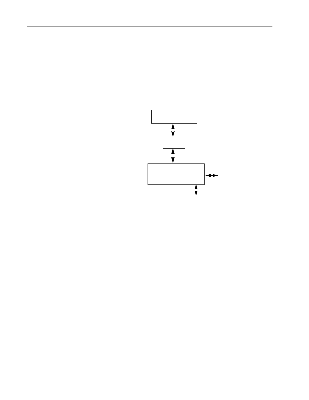
The 1746 I/O PCI Interface API
Use the 1746 I/O PCI Interface API to develop the software interface between your
application and the 1746 I/O PCI Interf ace scanner to control local I/O and to control
remote I/O via the 1747-SN or 1747-SDN scanners. The API provides calls for
typical control functions, such as:
• configuring I/O files
• initializing the scanner
• accessing the user LEDs, user jumper, and 3-position switch
• reading 1746 I/O PCI Interface status
• enabling/disabling forces
Application
API
1746 I/O PCI Interface
dual port memory
local I/O
remote I/O via
1747-SN or 1747-SDN
API Softwar e for DOS
The DOS API software provi des a library of C fun cti on cal l s f or DOS application
programs to interface with the dual port memory. The DOS API supports any
language compiler that uses the Pascal calling convention.
API Softwar e for Windows NT
The Windows NT API supports any programming languages that use the
Win32 _stdcall calling convention for application interface functions. The W indows
NT API function names are exported from a DLL in undecorated format to simplify
access from other progra mmi ng languages.
The Windows NT API software consists of two main components:
• the 1746 I/O PCI Interface device driver (OCdriver)
• the API library, which is a DLL (dynamically-linked library)
Publication 1747-6.5.3 June 1998
Page 11
Overview 1–3
The Windows NT API library is a DLL and mu st be installed on the system in order
to run an application wh ich uses it. The W indows NT API accesses the scanner vi a
the driver created for the bus interface The driver:
• allocates resources (interrupt and memory window)
• initializes scanner hardw are
• provides access to the scanner’s dual port RAM
• services interrupts from the scanner (priority messages)
Important: Only access the OCdriver through the AP I library functions.
When the OCdriver is loaded it tries to allocat e an inter rupt and a me mory window
for the memory and interr upt that were alloca ted usi ng the set tings by the PCI bus
at power-up for the dual port RAM.
Understanding the 1746 I/O PCI Interface Architecture
PCI bus
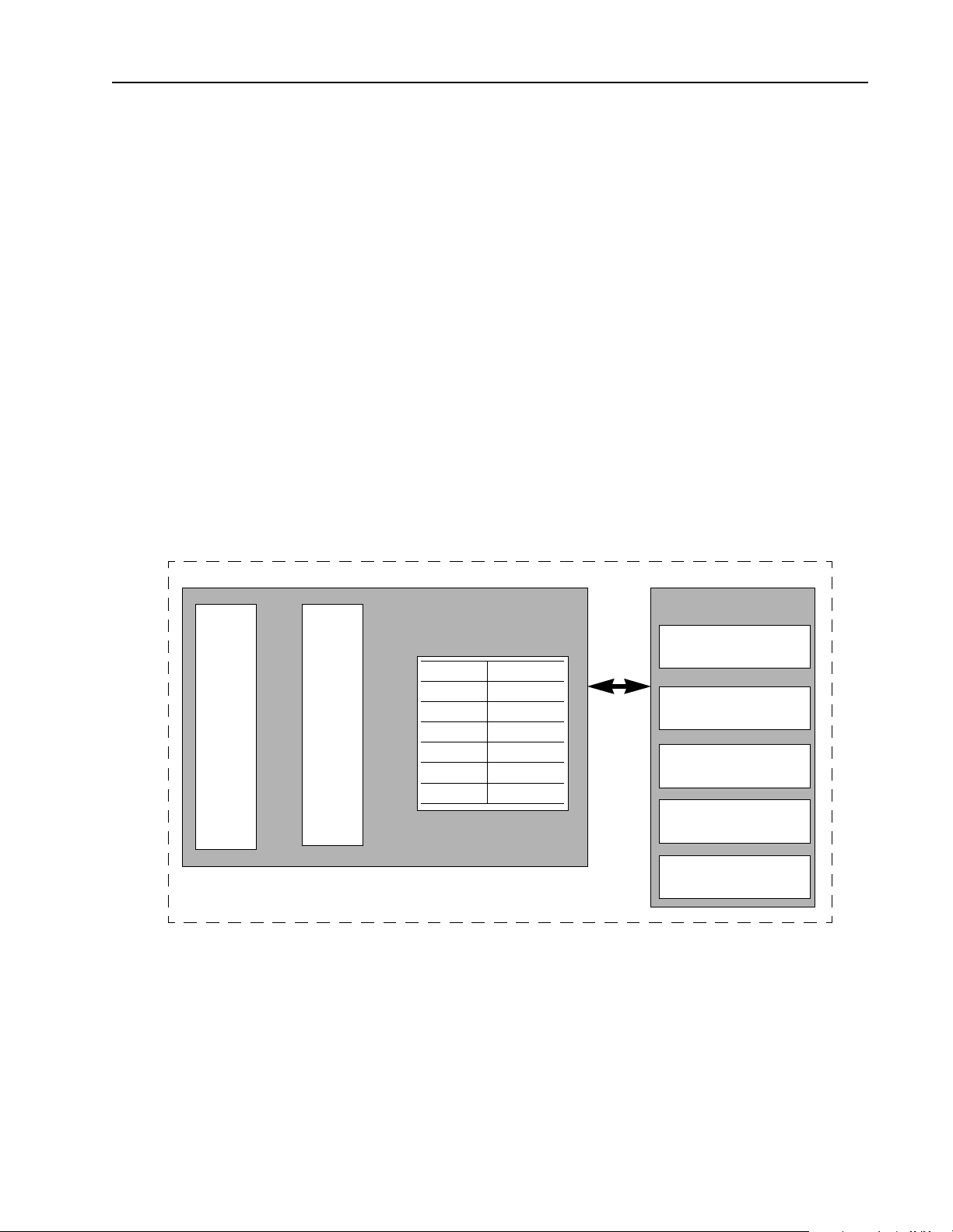
The 1746 I/O PCI Inter face archit ecture consists of a PCI card that plugs i nto a PC
and cables to a 1746 I/O chassis. The scanner scans the 1746 local I/O bus and reads/
writes inputs and outputs to/from the dual port registers.
1747-PCIS
Scanner
CPU
dual port memory
Partition: Bytes:
register 1K
commands variable
response variable
output image variable
input image variable
host data variable
cable
1747-PCIL
1746 backplane interface
status and user LEDs
3-position switch
user jumper
watchdog contact
The dual port is an 8K byte memory partition (optionally battery-backed) that
provides an int erface between the integrat ed scanner a nd your applic ation software
that resides on the host.
Important: The jumper for the battery-backed dual port memory is disabled by
default. You must switch the jumper in order to enable the dual port
memory battery-backed functi on. By enabling the battery-backed dual
port memory, you will decrease the life of the battery.
Publication 1747-6.5.3 June 1998
Page 12

1–4 Overview
Your application (the code y ou develop using the API ) u ses t he dual port memory
to communicate with the scann er to handle control functions on the 1746 backplane,
such as:
• scanner commands and responses
• battery and scanner status
• scan rate frequency and timing
• I/O image counters
• priority messages and interrupts
• semaphores to ensure data i ntegrity
• software-generated watchdogs
• control of the 4 user-definable LEDs, the 2-position jumper, and the 3-
position switch
The scanner functionality of the dual port supports I/O control functions, such as:
• synchronizing scans to the application
• forcing I/O
• defining discrete-input interrupts
• defining I/O module-driven interrupts (such as for the 1746-BAS module)
• enabling and disabling I/O slots
• resetting I/O
In addition to providing access to the co ntrol scanner, the dual port memory also
provides non-volatile (optional battery-backed) storage for:
• I/O values
• application parameters (timers, counters, presets)
Scanner Modes The scanner CPU operates in six basic modes:
• performing POST (power-on self test)
• waiting for h ost initializa tion
• Idle
• Scan
• Faulted
• non-recoverable fault
After the scanner successfully completes the POST, the scanner waits for an
initialization complete command from the application. Once the scanner receives
this command, the scanner enters Idle mode.
Before the sc anner can enter Scan mode, the application must download a valid
I/O configuration to the scanner.
Publication 1747-6.5.3 June 1998
If a recoverable fault occurs, the scanner enters Faulted mode. Use the
OC_ClearFa ult API function to clear the fault before the scanner can resume
operating in Scan mode.
Page 13

Overview 1–5
If a non-recoverable fault occurs, reset the scanner (cycle power). Some possible
non-recoverable faults include:
• POST failure
• background diagnostic failure
• internal watchdog timeout
Checking LED Indicators
PCI INTERFACE
STATUS BATT
LED 1 LED 2
LED 3 LED 4
Installing the DOS API
STATUS
The STATUS indicator reports the status of the scanner. The following table lists
the LED states for STATUS:
This state: Means: Take this action:
Yellow The scanner is running POST. None
Flashing green The scanner is in idle mode and is
not scanning I/O.
Solid green The scanner is scanning I/O. None
Flashing red An I/O fault has occurred. Check software to identify
Solid red A scanner internal fault has
occurred.
Off The adapter is not powered up. Turn on power.
To install the DOS API, copy the following files to a directory you create. The
sample code files are optional, but they show how to use the API functions.
None
fault condition.
Power system off and back on. If
the problem persists, service may
be required.
This file: Contains:
ocapil.lib API functions that you link to your application
ocapi.h API header file that contains API-referenced structures
sample.c Sample application program calling the API functions
sampleb.mak Sample make file for the Borland C compiler
samplem.mak Sample make file for the Microsoft C compiler
Publication 1747-6.5.3 June 1998
Page 14

1–6 Overview
Installing the Windows NT API
To install the Windows NT API, use the setup utility:
1. Insert the API diskette into a diskette drive.
It is recommended that you exit all applic ations before starting the setup process.
2. Select Run from th e startup men u, then se lect th e
setup.exe program from the
API diskette .
3. Click on OK to execute the s etup utility . Follow the displaye d instructions. Click
on Next.
4. The next dialog lets you choose whether to install the API development and
executable files (Complete) or the API executable files (Runtime), or just the
API development files (Development). To develop applications with the API,
you need the development files. To only run applications, only the runti me files
are necessary. The development files consist of an include file, import library,
and sample code. The runti me files consist of a d evice driver and a dynamical lylinked library.
Important: Runtime files may only be installed on a W indows NT system.
However, the development files may be installed on either
Windows NT or Windows 95 systems.
Choose the appropriate installation option and click on Next.
5. Specify the destination directory and click on Next.
6. The necessary fi les a re co pied to t he di sk, and th e syst em reg istr y i s updat ed to
include the OCdriver information.
7. Choose whether to reboot the system now or later and click on Finish.
Important: You must shutdown and reboot the scan ner before using the API. (T he
setup utility sets the registry Start parameter for OCd river to
Automatic; therefore, the service manager starts the OCdriver when
the system is booted.)
The Windows NT API uses these files:
This file: Contains:
ocapi.lib Import library in Microsoft COFF format
ocapi.h API header file that contains API-referenced structures
ocapi.dll API DLL
sample.c Sample application program calling the API functions
sampleb.mak Sample make file for the Borland C compiler
samplem.mak Sample make file for the Microsoft C compiler
Publication 1747-6.5.3 June 1998
Page 15

Overview 1–7
Installation Details
This section describes the actions the setup utility performs to install the API
and OCdriver.
If you select Runtime (Complete), the setup utility:
1. copies the device driver file,
%SystemRoot%\system32\drivers).
(
OCdriver, to the system device driver directory
2. adds this key and these values to the system registry:
HKEY_LOCAL_MACHINE\SYSTEM\CurrentControlSet\Services\OCdriver
ErrorControl: REG_DWORD 0x1
Group: REG_SZ Extended base
Start: REG_DWORD 0x2
Type: REG_DWORD 0x1
HKEY_LOCAL_MACHINE\SYSTEM\CurrentControlSet\Services\Drivers\ OCdriver
EventMessageFile= REG_EXPAND_SZ%SystemRoot%\System32\Drivers\OCdriver.sys
TypesSupported= REG_DWORD 0X00000007
3. copies the library file, OCapi.dll, to the %SystemRoot%\system32 directory.
If you select Runtime & Development, the setup utility performs the same steps as
for Runtime only and the setup ut ility copi es
ocapi.lib , ocapi.h, and the sample
source files to a development directory.
Uninstalling the Windows NT API
To uninstall Windo ws NT API, use the following instructions.
1. From the Control Panel, select Add/Remove Programs.
2. From the list of installed programs, select Open Control API.
3. Click on Add/Remove.
4. Click on Yes.
All of the API files and registry keys will be deleted.
Publication 1747-6.5.3 June 1998
Page 16

1–8 Overview
Notes:
Publication 1747-6.5.3 June 1998
Page 17

Chapter
2
Using the API
Introduction This chapter describes the API and how to use its components. For more information
about developing applications using the API, see chapter 3.
Getting Started To use the API, make sure you ha ve copied the following files to your development
directories. The sample files are optional.
This file: Contains:
ocapil.lib API functions that you link to your application (DOS only)
ocapi.lib Import library in Microsoft COFF format (Windows NT only)
ocapi.h API header file that contains API-referenced structures
ocapi.dll API DLL (Windows NT only)
sample.c Sample application program calling the API functions
sampleb.mak Sample MAKE file for the Borland C compiler
samplem.mak Sample MAKE file for the Microsoft C compiler
Your application must link to the appropriate library (
ocapi.lib
for Windows NT) and include ocapi.h. Y ou can copy the sample files
and adapt them for your application.
Programming Conventions
The API is supplied as an object code library file (ocapil.lib) or a DLL
ocapi.dll) that you link with the host application’s object code using
(
commercially-available tools.
This convention: Considerations:
The DOS API functions are specified using the C programming language syntax. To allow you to
develop control applications in other programming languages, the API functions use the standard
calling convention
header files
sample code
compiler support
Pascal calling convention.
The Windows NT API supports any programming languages that use the Win32 _stdcall calling
convention for application interface functions. The Windows NT API function names are exported
from the DLL in undecorated format to simplify access from other programming languages.
The API includes a header file (ocapi.h) tha t contains API function declarations, data structure
definitions, and other constant definitions. The header file is in standard C format.
The API comes with sample files to provide an example application that communicates with the
scanner. The sample files include all source files and MAKE files required to build the sample
application.
The DOS API is supplied in the large memory model, compatible with both Microsoft and Borland
compilers. The DOS library (ocapil.lib) is compiled as a 16-bit MS-DOS library using the
80386 instruction set.
The Windows NT library (ocapi.dll) is compiled for use with Microsoft Visual C++ or
Borland C++.
ocapil.lib for DOS or
Publication 1747-6.5.3 June 1998
Page 18

2–2 Using the API
DOS Considerations
The DOS API is as consistent as possible with APIs for other operating system
platforms. This makes it easier for you to migrate applications and it simplifies
support.
To create a consistent API, careful consideration was given to these requirements:
This requirement: Considerations:
The dual port RAM, or shared memory, is mapped automatically at power-up by the PCI bus in
the host processor’s memory address space on any even 8K boundary between 0xC0000 and
memory mapping
DOS interrupts An interrupt is automatically assigned to the scanner by the PCI bus at power-up.
control-break handler
0xDFFFF. For MS-DOS, it is important that any installed memory managers (such as EMM386)
or other TSR software avoid accessing the 8K dual port memory window.
Place the base memory select jumper in 1M position to allow the PCI BIOS to assign a base
memory address.
Because communication with the scanner requires memory and interrupt resources (as
described above), improper termination of the host application can leave these resources
allocated by the scanner and unusable by other applications. For this reason the API includes a
default control-break handler.
The default control-break handler is installed by OC_OpenScanner. If you press a [Ctrl-C]
[Ctrl-Break] key sequence, the following prompt is displayed:
or
Terminate Application? (Y/N) _
A response of Y properly exits the application; a response of N causes the application to continue.
If you need a different control-break handler, you must install it after calling the OC_OpenScanner
function. Always call the OC_CloseScanner function before exiting an application.
Publication 1747-6.5.3 June 1998
Page 19

Windows NT Considerations
During development, the application must be linked with an import library that
provides information ab out the functions contained within the DLL. The API import
library is compatible with the Microsoft linker. You can generate import libraries
for other programming languages from the DLL.
The Windows NT API can only be accessed by one process at a time. The API is
designed to be multi-t hread safe, so that mu lti-threaded co ntrol applicati ons can be
developed. Where necessary, the API functions acquire a mutex before accessing
the scanner interface. In this way, access to the scanner device is serialized. If the
mutex is in use by another thread, a threa d w ill be blocke d until it is fre ed.
T o crea te a consis te nt API, caref ul con sider at ion was given to th ese requi reme nts: :
This requirement: Considerations:
The NT API device driver detects the Scanner Adapter and automatically configures the memory
window address and inte rrupt assignment. The base memory address jump er must be positioned
to choose 32 bit addressing. The API and device driver must be installed on the system.
memory mapping
NT interrupts
Place the base memory select jumper in 32-bit position to allow the PCI BIOS to assign a base
memory address anywhere in 32-bit memory for protected-mode applications (WinNT). NT
device drivers (1747-PCINT) use the PCI BIOS or OS services to determine the memory window
base address and provide access to the dual port memory.
•To determine the allocated memory base address and interrupt, run the Windows NT
diagnostic found in Administrative Tools.
An interrupt is automatically assigned to the scanner by the PCI bus at power-up
•To determine the allocated memory base address and interrupt, run the Windows NT
diagnostic found in Administrative Tools.
Using the API 2–3
A group of thread-block ing functions are provided to aid mult i-threaded application
development. The functions are:
• OC_WaitForDII
• OC_WaitForEos
• OC_WaitForEosDmdOut
• OC_WaitForIoInt
• OC_WaitForDmdIn
• OC_WaitForExtError
For more information, see chap ter 6.
Publication 1747-6.5.3 June 1998
Page 20

2–4 Using the API
Tools to Use The API functions suppo rt both Microsoft and Bor land C compiler s. The AP I disk
includes sample MAKE files for each compiler.
When you use the DOS API and link t o
ocapil.lib, use the appropriate command-
line switch to select the large memory model. For more information, see your user
manual for your compiler.
If you plan to use a programming language other than C, make sure the programming
language follows the appropriate calling convention (Pascal for the DOS API;
Win32 _stdcall for Windows NT). After you write your application, use your
compiler to link to
ocapil.lib (DOS) or ocapi.lib (Windows NT).
Publication 1747-6.5.3 June 1998
Page 21

Using the API 2–5
Sample DOS MAKE file for Borland compilers
The following sample file shows how to use a Borland MAKE file. The bold
headings indicate the statements you need to modify for your environment.
#************************************************************************
#
# Title: Makefile for Open Controller API Sample
#
# Abstract:
# This file is used by the Borland MAKE utility to build the
# sample application.
#
# Environment:
# 1747-OCE Open Controller
# MS-DOS
# Borland C/C++ Compiler (16-bit)#
#************************************************************************
#
# Paths to Tools
#
# Note: Modify the following paths to
# correspond to your environment.
#
#---------------------------------------------CPATH = D:\BC5 # Location of Borland tools
CC = $(CPATH)\bin\Bcc # compiler
LINK = $(CPATH)\bin\TLink # linker
MAKE = $(CPATH)\bin\Make # make utility
#---------------------------------------------# Path to API Library and Include file
#
# Note: Modify the following path to
# correspond to your environment.
#
#---------------------------------------------APILIB = ..\ocapil.lib # Path to Open Controller API library
APIINC = .. # Path to Open Controller API include file
#---------------------------------------------# Options
#---------------------------------------------CFLAGS = -c -v- -w -ml -I$(APIINC)
LFLAGS = -v- -Tde -d -c
sample.exe : sample.obj $(APILIB) sampleb.mak
$(LINK) $(LFLAGS) c0l sample.obj, $*.exe, $*.map, $(APILIB) cl
clean:
del *.exe
del *.obj
del *.map
rebuild:
$(MAKE) clean
$(MAKE)
.c.obj:
$(CC) $(CFLAGS) $*.c
sample.obj: sample.c $(APIINC)\ocapi.h
sampleb.mak
Publication 1747-6.5.3 June 1998
Page 22

2–6 Using the API
Sample DOS MAKE file for Microsoft compilers
The following sample file shows how to use a Microsoft MAKE file. The bold
headings indicate the statements you need to modify for your environment.
#************************************************************************
#
Title: Makefile for Open Controller API Sample
#
# Abstract:
# This file is used by the Microsoft NMake utility to build the
# sample application.
#
# Environment:
# 1747-OCE Open Controller
# MS-DOS
# Microsoft C/C++ Compiler (16-bit)
#************************************************************************
#---------------------------------------------# Note: The enviro nm en t va ri ab le s LI B an d
# INCLUDE must be set to the path to the
# Microsoft C libr ar y an d in cl ud e fi le s.
# For example:
#
# set LIB=D:\MSVC15\LIB
# set INCLUDE=D:\MSVC15\INCLUDE
#
#---------------------------------------------# Paths to Tools
#
# Note: Modify the following paths to
# correspond to your environment.
#
#---------------------------------------------CPATH = D:\MSVC15 # Location of Microsoft tools
CC = $(CPATH)\bin\cl # compiler
LINK = $(CPATH)\bin\link # linker
MAKE = $(CPATH)\bin\nmake # make utility
#---------------------------------------------# Path to API Library and Include file
#
# Note: Modify the following path to
# correspond to your environment.
#
#---------------------------------------------APILIB = ..ocapil.lib # Path to Open Controller API library
APIINC = .. # Path to Open Controller API include file
#---------------------------------------------# Options
#----------- -- -- -- -- -- -- -- -- -- -- -- -- -- -- -- -- -- CFLAGS = /c /nologo /G3 /W3 /AL /Oi /D /Gx- /I $(APIINC)
LFLAGS = /MAP:A /NOI /PACKC
sample.exe : sample.obj $(APILIB) samplem.mak
$(LINK) $(LFLAGS) sample.obj, $*.exe, $*.map, $(APILIB), nul.def
clean:
del *.exe
del *.obj
del *.map
rebuild:
$(MAKE) -f samplem.mak clean
$(MAKE) -f samplem.mak
.c.obj:
$(CC) $(CFLAGS) $*.c
sample.obj: sample.c $(APIINC)\ocapi.h
samplem.mak
Publication 1747-6.5.3 June 1998
Page 23

Using the API 2–7
Sample Windows NT MAKE file for Microsoft compilers
The following sample file shows how to use a Microsoft MAKE file. The bold
headings indicate the statements you need to modify for your environment.
#************************************************************************
# Title: Makefile for Open Controller NT API Sample
#
# Abstract:
# This file is used by the Microsoft NMake utility to build the
# sample application.
#
# Environment:
# 1747-OCE Open Controller
# Microsoft Windows NT 4.0
# Microsoft Visual C++
#
# (c)Copyright Allen-Bradley
#
#************************************************************************
#---------------------------------------------# Note: The environment variable LIB
# must be set to the path to the
# Microsoft C library files.
# For example:
#
# set LIB=D:\MSDEV\LIB
#
#---------------------------------------------# Paths to Tools
#
# Note: Modify the following paths to
# correspond to your environment.
#
#---------------------------------------------CPATH = D:\MSDEV # Location of Microsoft tools
CC = $(CPATH)\bin\cl # compiler
LINK = $(CPATH)\bin\link # linker
MAKE = $(CPATH)\bin\nmake # make utility
#---------------------------------------------# Path to API Library and Include file
#
# Note: Modify the following paths to
# correspond to your environment.
#
#---------------------------------------------APILIB = ..\api\lib\ocapi.lib # Path to Open Controller API library
APIINC = ..\api\include # Path to Open Controller API include file
#---------------------------------# Compiler/Linker Debugging Options
# (Define DEBUG for debugging.)
#---------------------------------!ifdef DEBUG
CDEBUG = -Zi -Od
LDEBUG = -debug:full -debugtype:cv
!else
CDEBUG = -Ox
LDEBUG = /RELEASE
Publication 1747-6.5.3 June 1998
Page 24

2–8 Using the API
!endif
#------------------------------------------# Compiler Options
#
# -W3 Turn on warnings
# -GB Optimize code for 80486/Pentium
# -MT Use Multithreaded runtime lib
#
#------------------------------------------CFLAGS = -W3 -GB -MT \
-I$(APIINC) -I$(CPATH)\include
#---------------------------------# Linker Options
#
#---------------------------------LFLAGS = /NODEFAULTLIB /SUBSYSTEM:CONSOLE \
/INCREMENTAL:NO /PDB:NONE
#-----------------------------------# Libraries
#
# libcmt Multithreaded C runtime
# kernel32 Base system lib
#
#-----------------------------------LIBS = libcmt.lib kernel32.lib
#--------------------------------# Final target
#--------------------------------sample.exe : sample.obj $(APILIB)
$(LINK) @<<
$(LDEBUG) $(LFLAGS) $(LIBS) $**
<<
@echo Finished
clean:
del *.exe
del *.obj
del *.map
rebuild:
$(MAKE) -f samplem.mak clean
$(MAKE) -f samplem.mak
#-------------------------# Intermediate target rules
#-------------------------.c.obj:
$(CC) @<<
/c $(CDEBUG) $(CFLAGS) $*.c
<<
#--------------------------------# Intermediate target dependancies
#---------------------------------
sample.obj: sample.c $(APIINC)\ocapi.h
samplem.mak
Publication 1747-6.5.3 June 1998
Page 25

Using the API 2–9
Sample Windows NT MAKE file for Borland compilers
The following sample file shows how to use a Borland MAKE file. The bold
headings indicate the statements you need to modify for your environment.
#************************************************************************
#
# Title: Makefile for Open Controller API Sample
#
# Abstract:
# This file is used by the Borland MAKE utility to build the
# sample application.
#
# Environment:
# 1747-OCE Open Controller
# Microsoft Windows NT 4.0
# Borland C++ Compiler
#
# (c)Copyright Allen-Bradley
#
#************************************************************************
#---------------------------------------------# Paths to Tools
#
# Note: Modify the following paths to
# correspond to your environment.
#
#---------------------------------------------CPATH = D:\BC5 # Location of Borland tools
CC = $(CPATH)\bin\Bcc32 # compiler
LINK = $(CPATH)\bin\TLink32 # linker
MAKE = $(CPATH)\bin\Make # make utility
#---------------------------------------------# Path to API Library and Include file
#
# Note: Modify the following path to
# correspond to your environment.
#
#---------------------------------------------APIDLL = ..\api\lib\ocapi.dll # Path to Open Controller API library
APIINC = ..\api\include # Path to Open Controller API include file
APILIB = .\ocapi.lib # Borland compatible import library
#---------------------------------------------# Options
#---------------------------------------------CFLAGS = -c -v -4 -tWM -w -I$(APIINC)
LFLAGS = -v -Tpe -d -c -ap -r
#---------------------------------------------# Final Target
#---------------------------------------------sample.exe : sample.obj $(APILIB) sampleb.mak
$(LINK) @&&|
$(LFLAGS) +
D:\BC5\LIB\c0x32.obj +
$*.obj, $*.exe, $*.map
D:\BC5\LIB\import32.lib +
D:\BC5\LIB\cw32mt.lib +
$(APILIB)
Publication 1747-6.5.3 June 1998
Page 26

2–10 Using the API
|
clean:
del *.exe
del *.obj
del *.map
del *.lib
rebuild:
$(MAKE) -f sampleb.mak clean
$(MAKE) -f sampleb.mak
.c.obj:
$(CC) $(CFLAGS) $*.c
#---------------------------------------------# Create a Borland-compatible import library
#---------------------------------------------$(APILIB): $(APIDLL)
implib $(APILIB) $(APIDLL)
sample.obj: sample.c $(APIINC)\ocapi.h sampleb.mak
Publication 1747-6.5.3 June 1998
Page 27

Chapter
3
Developing Applications
Introduction This chapter describ es the proper progra mming sequence for your a pplication. This
chapter also describes how to partition the dual port memory in the 1746 I/O PCI
Interface.
How the API Functions Are Organized
Each of the API functions falls into one of these four categories:
• scanner initialization
• scanner I/O configuration
• data input/output
• user interface/miscellaneous
Chapter 6 describes each API function and identifies its functionality group.
Publication 1747-6.5.3 June 1998
Page 28
3–2 Developing Applications
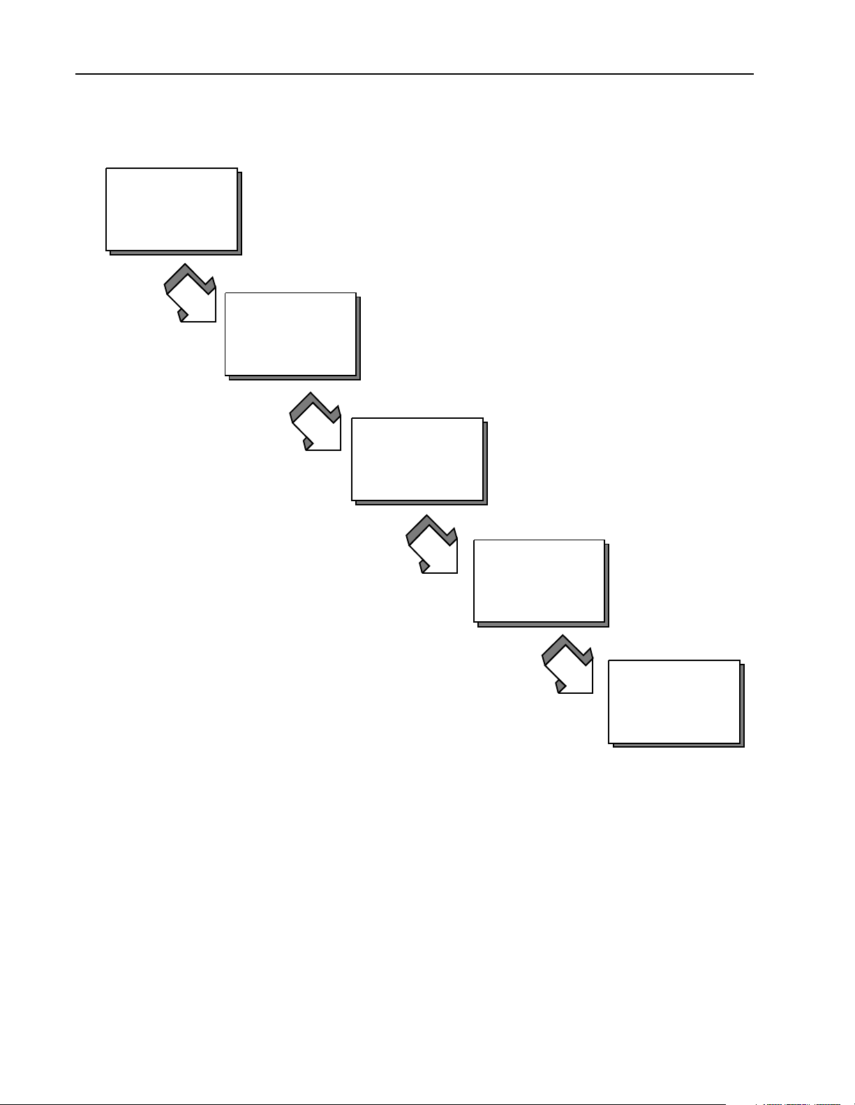
Programming Sequence
1
Access the scanner
Follow this programming sequence when you develop your application.
2
2
Initialize the scanner
Initialize the scanner
3
Configure the scanner
4
Control scanner
operation
5
Scan I/O
Access the scanner
The host applicatio n must first call OC_OpenScanner to ga in access to t he scanner .
Once an applicati on has access, no other applicat ion can gain access to the s canner .
When the application no longer requires access to the scanner, it must call
OC_CloseScanner to release access of the scanner to other applications.
Once the scanner is opened, you must call OC_CloseScanner before exiting
the application.
Publication 1747-6.5.3 June 1998
Page 29

Developing Applications 3–3
Initialize the scanner
After the scanner is reset and performs its POST, the scanner waits for initialization.
In this state, the scanner can’t be configured or control I/O. The only ope rational
function is that which co ntrols the LE Ds. Any call to a function that requires the
scanner to be initialized returns an error. You must initialize the scanner by sending
it partitioning information before the host applicat ion can commun icate with the
scanner.
Initialize the scanner by calling the OC_InitScanner function to send the scanner
partitioning information, which defines in bytes the size of the output image, the
input image, and the host retentive data. Each of these memory segments must be
at least large eno ugh t o hold their respective data, and must be an even number. If
the input or out put partit ion is init ialized s maller t han the actua l size of the input or
output image for a configuration, the OC_DownloadIOConfiguration function
returns an error. The host retentive data size is optional and can be 0.
To determine the input image and output image sizes, use the
OC_CreateIOConfiguration function to create an I/O configuration.
OC_CreateIOConfigurati on returns an I/O co nfiguratio n with the number of by tes
of inputs and outputs for each module. If a configuration already exists, you can
use OC_GetIOConfig to return the current I/O configuration. The application can
then calculate the minimum size of the segments required to hold the input and
output images. For more information, see page 3-18.
The API has a defined constant specifying the total number of bytes available for
the three segmenters This constant is specified as:
OCSEGMENTSIZELIMIT
Once the scanner has been initialized properly it cannot be re-initialized unless it
is reset with the OC_ResetScanner function. Once the scanner is reset, scanner
communications are disabled again until the scanner is initialized. The host
application can call OC_GetScannerStatus to determine if the scanner has been
initialized.
If the scanner was previously initialize d, the host app lication can retrieve the
initialization partition information with the OC_GetScannerInitInfo function
instead of resetting and re-initializing the scanner.
Configure the scanner
T o access I/O modules in a ra ck, you must define the rack sizes and installed module
types for the scanner. You can either create a specific configuration or read the
current configuration. The scanner cannot be set to Scan mode until it has been
configured (received a valid scanner configuration).
If the scanner is in Scan mode and the host applic ation has not downloaded a scanne r
configuration, the scanner has already been configured. To control I/O, use
OC_GetIOConfiguration to retrieve the current scanner configuration.
Publication 1747-6.5.3 Junel 1998
Page 30

3–4 Developing Applications
The application can read the current I/O configuration with the
OC_GetIOConfiguration fu nction. If the scanner is not in Scan mode, this fu nction
returns the curre nt scan ner conf igu rati on which ca n be down loaded to th e scanne r
using OC_DownloadIOConfiguration.
If the application requires a specific I/O configuration, the application can define
the I/O configuration structure with the rack sizes and module types installed in
each slot. The application passes this configuration structure to
OC_CreateIOConfiguration. OC_CreateIOConfiguration returns a scanner
configuration that can be downloaded to the scanner. For more information, see
chapter 5.
Once a valid scanner configuration is successfully downloaded to the scanner via
OC_DownloadIOConfiguration, the application can set the scanner to Scan mode
and control I/O.
Both OC_CreateIOConfiguration and OC_GetIOConfiguration build the
configuration data from an internal database of supported I/O modules.
Control scanner operation
Once the scanner has been confi gured, the application can control scanner op eration.
The host application can:
• set the scanner to Idle or Scan mode
• control the scan time
• control I/O
• read or write module files
• clear faults
• enable/dis able slots
• set I/O Idle state
• install/remove forces
• handle module interrupts and discrete input interrupts
The API uses messages to communicate with the scanner. The scan time settings
affect the time allowed by the scanner to process a message. OC_SetScanTi me
adjusts the scan time of the application.
The scanner processes messages during any available time that it is not scanning
I/O. If the scan time is set too small, some API functions might take a relatively
long time to complete. If some functions seem to be taking too long to complete,
increase the scan time t o provide more time fo r the scanner t o process message s. If
the scan time is set too la r ge, I/ O won’ t upd at e fast eno ugh. For inf ormati on about
estimating scan time, see PCIS Bus Card for 1746 Local I/O Installation
Instructions, publication 1747-5.31.
Publication 1747-6.5.3 June 1998
Page 31

Developing Applications 3–5
Scan I/O
The scanner provides two basic methods for scanning I/O: timed scans and
on-demand scans. The host application can use either, or a combination of both.
Typically, the scanner reads inputs from modules and writes outputs to modules
once every scan time. To read inputs and write outputs, the application calls
OC_ReadInputImage and OC_WriteOutputImage independently from the
scanner’s scan sequence.
The application can ch ange the beh avior of t he input a nd output s cans by all owing
the application to have more control over I/O s canning. The application c an prevent
the scanner from doing any output scans and allow the application to read inputs
and initialize ou tputs befor e the sca nner begi ns to wri te output s. This mode allows
the application to pre-scan the inputs before the outputs are written.
The application can set the scanner to a conditional scan mode where the scanner
writes outputs at the next scan time after the application writes data to the output
image. In this mode, the sc anner only writes outputs each time t he application writes
data to the output image.
The application can also pre vent output sca ns by the scanner and have the scanner
send a message after every input scan. The application can detect an end-of-scan
message and then read the input image, perform logic, and write outputs using
OC_DemandOutputScan to force the scanner to write outputs immediately. This
lets the application synchronize its control loop with the input and output scans.
The application can also disable both input and output scans. In this mode, the
scanner is a slave and input or output scans on ly take place when r equested by the
host application.
Publication 1747-6.5.3 Junel 1998
Page 32

3–6 Developing Applications
Programming Example for DOS
/************************************************************************
*
* FILE:sample.c
*
* PURPOSE:Sample application code for 1746 I/O PCI Interface API
*
* SUMMARY:This program,
* - Resets and initializes the scanner.
* - Displays the scanner firmware and hardware versions.
* - Autconfigures the I/O in chassis.
* - Reads the front panel switch position and lights LED 1.
* - Reads first discrete input module data word.
* - Writes incremental data to first output module data word.
* - Closes connection to scanner and exits.
*
* ENVIRONMENT:1747-PCIS 1746 I/O PCI Interface
* MS-DOS
* Borland/Microsoft C/C++ Compiler (16-bit)
*
************************************************************************/
/*=======================================================================
= INCLUDE FILES =
=========================================================================*/
The following DOS example (sample.c on your API disk) shows how to pr ogram
the above steps. Callouts on the right margin identify the code for each step.
#include ”ocapi.h”
#include <stdio.h>
#include <dos.h>
#include <time.h>
#include <conio.h>
#include <string.h>
/*=======================================================================
= MODULE WIDE GLOBAL VARIABLES =
=========================================================================*/
HANDLE Handle; /* Software ID to scanner device */
OCIOCFG OCcfg; /* Chassis I/O config. data structure */
/*=======================================================================
= FUNCTION PROTOTYPES =
=========================================================================*/
void Ioexit( int );
/*=======================================================================
= MAIN PROGRAM =
=========================================================================*/
void main()
{
int retcode; /* Return code from API calls */
int i;
int slots;
int input_slot, input_found = 0;
int output_slot, output_found = 0;
OCINIT ocpart;
BYTE status;
OCVERSIONINFO verinfo;
BYTE swpos;
WORD wData;
Publication 1747-6.5.3 June 1998
Page 33

Developing Applications 3–7
/*
** Open the scanner
*/
retcode = OC_OpenScanner( &Handle, 0, 0);
if ( retcode != SUCCESS )
{
printf( ”\nERROR: OC_OpenScanner failed: %d\n”, retcode );
Ioexit( 1 );
}
/*
** Reset the scanner
*/
printf( ”\n\n Going to reset OC, takes 6 seconds to complete...\n” );
retcode = OC_ResetScanner( Handle, OCWAIT );
if ( retcode != SUCCESS )
{
printf( ”\nERROR: OC_ResetScanner failed: %d\n”, retcode );
Ioexit( 1 );
}
/*
** Check scanner status register
*/
retcode = OC_GetScannerStatus( Handle, &status );
if ( retcode != SUCCESS )
{
printf( ”\nERROR: OC_GetScannerStatus failed: %d\n”, retcode );
Ioexit( 1 );
}
Access the
scanner
See page 6-48.
Initialize the
scanner
See pages
6-63, 6-33,
and 6-7.
if ( status != SCANSTS_INIT)
{
printf(”\nERROR: POST failure detected: %d\n”, status);
Ioexit(1);
}
/*
** Initialize the DPR partitions
** You can use OC_CreateIOConfiguration to determine the I/O image table
** sizes before paritioning the DPR
*/
ocpart.OutputImageSize = 0x800;
ocpart.InputImageSize = 0x800;
ocpart.HostRetentiveDataSize = 0;
retcode = OC_InitScanner( Handle, &ocpart );
if ( retcode != SUCCESS )
{
printf(” \nERROR: OC_InitScanner failed: %d\n”, retcode );
Ioexit( 1 );
}
/*
** Display software/hardware versions
*/
retcode = OC_GetVersionInfo( Handle, &verinfo );
if ( retcode != SUCCESS )
{
printf( ”\nERROR: OC_GetVersionInfo failed: %d\n”, retcode );
Ioexit( 1 );
}
printf( ”\n\n Scanner Firmware Series: %02d Revision: %02d ”,
verinfo.ScannerFirmwareSeries, verinfo.ScannerFirmwareRevision );
printf( ”\n Hardware Series: %02d Revision: %02d”,
verinfo.OCHardwareSeries, verinfo.OCHardwareRevision );
delay( 3000 );
Publication 1747-6.5.3 Junel 1998
Page 34

3–8 Developing Applications
/*
** Read switch position
*/
retcode = OC_GetSwitchPosition( Handle, &swpos );
if ( retcode != SUCCESS )
{
printf( ”\nERROR: OC_GetSwitchPosition failed: %d\n”, retcode );
Ioexit( 1 );
}
printf( ”\n\n Switch position: ” );
switch( swpos )
{
case SWITCH_TOP:
printf( ”Top \n” );
break;
case SWITCH_BOTTOM:
printf( ”Bottom \n” );
break;
case SWITCH_MIDDLE:
printf( ”Middle \n” );
}
delay( 3000 );
/*
** Read auto-config
*/
retcode = OC_GetIOConfiguration( Handle, &OCcfg );
if ( retcode != SUCCESS )
{
}
break;
printf( ”\nERROR: OC_GetIOConfiguration failed: %d\n”, retcode );
Ioexit( 1 );
/*
** Display rack configuration
*/
slots = OCcfg.Rack1Size + OCcfg.Rack2Size + OCcfg.Rack3Size;
if ( slots > 31 )
slots = 31;
printf( ”\n\n Chassis configuration ” );
for ( i=1; i < slots; i++ )
{
if ( OCcfg.SlotCfg[i].type != 0xff )
printf( ”\n Slot %2d: Type %2d, Mix %3d %s”,
i, OCcfg.SlotCfg[i].type, OCcfg.SlotCfg[i].mix,
else
/* Find digital input card */
if ( OCcfg.SlotCfg[i].mix < 8 && !input_found )
{
}
/* Find digital output card */
if ( (OCcfg.SlotCfg[i].mix > 7) && (OCcfg.SlotCfg[i].mix < 32) && !output_found )
{
}
}
delay( 3000 );
OCcfg.SlotCfg[i].Name );
printf( ”\n Slot %2d: %s”, i, OCcfg.SlotCfg[i].Name );
input_found = 1;
input_slot = i;
output_found = 1;
output_slot = i;
Publication 1747-6.5.3 June 1998
Page 35

/*
** Download the configuration to the scanner
*/
retcode = OC_DownloadIOConfiguration( Handle, &OCcfg );
if ( retcode != SUCCESS )
{
printf( ”\nERROR: OC_DownloadIOConfiguration failed: %d\n”, retcode );
Ioexit( 1 );
}
/*
** Set output update mode to always
*/
retcode = OC_SetOutputUpdateMode( Handle, OUTUPD_ALWAYS );
if ( retcode != SUCCESS )
{
printf( ”\nERROR: OC_SetOutputUpdateMode failed: %d\n”, retcode );
Ioexit( 1 );
}
/*
** Set scan time to 5ms, periodic scan mode
*/
retcode = OC_SetScanTime( Handle, SCAN_PERIODIC, 20 );
if ( retcode != SUCCESS )
{
printf( ”\nERROR: OC_SetScanTime failed: %d\n”, retcode );
Ioexit( 1 );
}
Developing Applications 3–9
Configure
the scanner
See page
6-11.
Control scanner
operation
See pages 6-70
and 6-73.
/*
** Goto Scan Mode
*/
retcode = OC_SetScanMode( Handle, SCAN_RUN );
if ( retcode != SUCCESS )
{
printf( ”\nERROR: OC_SetScanMode failed: %d\n”, retcode );
Ioexit( 1 );
}
/*
** Turn on User LED 1
*/
retcode = OC_SetUserLEDState( Handle, 1, LED_GREEN_SOLID );
if ( retcode != SUCCESS )
{
printf( ”\nERROR: OC_SetUserLEDState failed: %d\n”, retcode );
Ioexit( 1 );
}
printf( ”\n\n LED1 is on solid green now. \n” );
delay( 3000 );
Publication 1747-6.5.3 Junel 1998
Page 36

3–10 Developing Applications
/*
** Read first Input word
*/
retcode = OC_ReadInputImage( Handle, NULL, input_slot, 0, 1, &wData );
if ( retcode != SUCCESS )
{
printf( ”\nERROR: OC_ReadInputImage failed: %d\n”, retcode );
Ioexit( 1 );
}
printf( ”\n\n First input image data word --> 0x%04x \n”, wData );
delay( 3000 );
/*
** Write to the first Output word
*/
printf( ”\n\n Incrementing first discrete output word. \n” );
for ( wData=0; wData < 256; wData++)
{
retcode = OC_WriteOutputImage( Handle, NULL, output_slot, 0, 1, &wData );
if ( retcode != SUCCESS )
{
printf(”\nERROR: OC_WriteOutputImage failed: %d\n”, retcode);
Ioexit(1);
}
delay ( 10 );
}
/*
** Must always close the scanner before exiting
*/
OC_CloseScanner( Handle );
Scan I/O
See page
6-54 and
6-90.
printf( ”\n\n Program is done! \n\n” );
} /* end main() */
Publication 1747-6.5.3 June 1998
Page 37

Developing Applications 3–11
/************************************************************************
*
* Name: Ioexit
*
* Description:
*
* Common error handling routine. This routine displays any
* extended error and exits the program.
*
* Arguments:
* retcode : int( input )
* This error code is passed to the exit() routine.
*
* External effects:
* The program is terminated.
*
* Return value:
* none
*
************************************************************************/
void Ioexit( int retcode )
{
OCEXTERR exterr;
char *msg;
if (OC_GetExtendedError(Handle, &exterr) == SUCCESS)
{
if ( exterr.ErrorCode != 0 )
{
OC_ExtendedErrorMsg(Handle, &exterr, &msg);
printf(”\nERROR: %s\n”, msg);
}
}
OC_CloseScanner(Handle);
exit(retcode);
} /* end Ioexit() */
Publication 1747-6.5.3 Junel 1998
Page 38

3–12 Developing Applications
Programming Example for Windows NT
/********************************************************************
* Title: Simple application sample code for 1746 I/O PCI Interface API
*
* Abstract:
*
* This file contains a simple application using the PCI
* bus interface API.
*
* Environment:
* 1747-PCIS 1746 I/O PCI Interface
* Microsoft Windows NT 4.0
* Microsoft Visual C++ / Borland C++
* (c)Copyright Allen-Bradley *
************************************************************************/
/*=======================================================================
= INCLUDE FILES =
=======================================================================*/
#include <windows.h>
#include <process.h>
#include <stdio.h>
#include <stdlib.h>
#include <time.h>
#include <conio.h>
#include <string.h>
#include "ocapi.h"
The following W indows NT example (sample.c on yo ur Windows NT API disk )
shows how to program the above steps. Callouts on the right margin identify the
code for each step.
/*=======================================================================
= MODULE WIDE GLOBAL VARIABLES =
=======================================================================*/
HANDLE OChandle;
OCIOCFG OCcfg;
/************************************************************************
* Entry point:
* Ioexit
*
* Description:
* Common error handling routine. This routine displays any
* extended error and exits the program.
*
* Arguments:
* rc : int ( input )
* This error code is passed to the exit() routine.
*
* External effects:
* The program is terminated.
*
* Return value:
* none
*
* Access: Public
* ----------------------------------------------------------------------* Notes:
*
*************************************************************************/
void Ioexit
int rc
) {
OCEXTERR exterr;
char *msg;
Publication 1747-6.5.3 June 1998
Page 39

Developing Applications 3–13
if (OC_GetExtendedError(OChandle, &exterr) == SUCCESS)
{
if ( exterr.ErrorCode != 0 )
{
OC_ExtendedErrorMsg(OChandle, &exterr, &msg);
printf("\n\nERROR: %d %s\n", msg, exterr.ErrorCode);
}
}
OC_CloseScanner(OChandle);
exit(rc);
} /* end Ioexit() */
/*************************************************************************
* Entry point:
* tErrorEvent
*
* Description:
* Thread to handle errors.
*
* Arguments:
* none
*
* External effects:
* none
*
* Return value:
* none
*
* Access: Public
*
*----------------------------------------------------------------------* Notes:
*
************************************************************************/
void tErrorEvent( void *dummy )
{
while(1)
{
/* Sleep until the scanner reports an error */
OC_WaitForExtError(OChandle, INFINITE);
/* An error has occurred. Perform whatever error handling */
/* that is necessary. In this case, we just print a message */
/* and exit the process. */
Ioexit(1);
}
} /* end tErrorEvent() */
Publication 1747-6.5.3 Junel 1998
Page 40

3–14 Developing Applications
/************************************************************************ *
* Entry point:
* main
*
* Description:
* Entry point of the PCI I/O bus interface API sample application.
*
* This program resets, initializes, and autoconfigures the scanner.
* It displays the scanner firmware and hardware versions, and
* the front panel switch position.
* It lights User LED 1, reads inputs from a 32 pt discrete
* input module, and writes data to the M0 file on a BAS module.
*
* Arguments:
* none
*
* External effects:
* none
*
* Return value:
* 0 if no errors were encountered
* 1 if errors
*
* Access: Public
*
*----------------------------------------------------------------------* Notes:
*
************************************************************************/
main()
{
int rc;
int i;
int slots;
int BASslot;
int IB32slot;
int fRecreateIOcfg;
OCINIT ocpart;
BYTE status;
OCVERSIONINFO verinfo;
BYTE swpos;
WORD wData,wLen;
BYTE temp;
BASslot = IB32slot = 0;
fRecreateIOcfg = 0;
/* Open the scanner */
if (SUCCESS != (rc = OC_OpenScanner(&OChandle)))
{
printf("\nERROR: OC_OpenScanner failed: %d\n", rc);
Ioexit(1);
}
/* Create an error-handling thread */
if (-1 == (long) _beginthread(tErrorEvent, 0, NULL))
printf("\nERROR: _beginthread tErrorEvent failed.\n");
Publication 1747-6.5.3 June 1998
Access the
scanner
See page
6-48.
Page 41

/* Reset the scanner */
printf("\nResetting the scanner...");
if (SUCCESS != (rc = OC_ResetScanner(OChandle, OCWAIT)))
{
printf("\nERROR: OC_ResetScanner failed: %d\n", rc);
Ioexit(1);
}
/* Check scanner status register */
if (SUCCESS != (rc = OC_GetScannerStatus(OChandle, &status)))
{
printf("\nERROR: OC_GetScannerStatus failed: %d\n", rc);
Ioexit(1);
}
if ( status != SCANSTS_INIT)
{
printf("\nERROR: POST failure detected: %d\n", status);
Ioexit(1);
}
/* Initialize the DPR partitions */
ocpart.OutputImageSize = 0x800;
ocpart.InputImageSize = 0x800;
ocpart.HostRetentiveDataSize = 0;
if (SUCCESS != (rc = OC_InitScanner(OChandle, &ocpart)))
{
printf("\nERROR: OC_InitScanner failed: %d\n", rc);
Ioexit(1);
}
Developing Applications 3–15
Initialize the
scanner
See pages
6-63, 6-33,
and 6-46.
/* Display software/hardware versions */
if (SUCCESS != (rc = OC_GetVersionInfo(OChandle, &verinfo)))
{
printf("\nERROR: OC_GetVersionInfo failed: %d\n", rc);
Ioexit(1);
}
printf("\nOC API Series: %02d Revision: %02d ",
verinfo.APISeries,verinfo.APIRevision);
printf("\nOCdriver Series: %02d Revision: %02d ",
verinfo.OCdriverSeries, verinfo.OCdriverRevision);
printf("\nOC Scanner Firmware Series: %02d Revision: %02d ",
verinfo.ScannerFirmwareSeries, verinfo.ScannerFirmwareRevision);
printf("\nOC Hardware Series: %02d Revision: %02d\n",
verinfo.OCHardwareSeries, verinfo.OCHardwareRevision);
/* Read switch position */
if (SUCCESS != (rc = OC_GetSwitchPosition(OChandle, &swpos)))
{
printf("\nERROR: OC_GetSwitchPosition failed: %d\n", rc);
Ioexit(1);
}
printf("\nSwitch position: ");
switch(swpos)
{
case SWITCH_TOP:
printf("Top");
break;
case SWITCH_BOTTOM:
printf("Bottom");
break;
case SWITCH_MIDDLE:
printf("Middle");
break; }
/* Read temperature */
if (SUCCESS != (rc = OC_GetTemperature(OChandle, &temp)))
{
printf("\nERROR: OC_GetTemperature failed: %d\n", rc);
Ioexit(1);
}
printf("\nTemperature: %dC ", temp);
Publication 1747-6.5.3 Junel 1998
Page 42

3–16 Developing Applications
/* Read auto-config */
if (SUCCESS != (rc = OC_GetIOConfiguration(OChandle, &OCcfg)))
{
printf("\nERROR: OC_GetIOConfiguration failed: %d\n", rc);
Ioexit(1);
}
/* Display rack configuration */
slots = OCcfg.Rack1Size + OCcfg.Rack2Size + OCcfg.Rack3Size;
if ( slots > 31 ) slots = 31;
printf("\n\nRack configuration:");
for (i=1; i<slots; i++)
{
if (OCcfg.SlotCfg[i].type != 0xff)
{
printf("\nSlot %2d: Type %2d, Mix %3d %s",
i, OCcfg.SlotCfg[i].type, OCcfg.SlotCfg[i].mix,
OCcfg.SlotCfg[i].Name);
}
else
{
printf("\nSlot %2d: %s", i, OCcfg.SlotCfg[i].Name);
}
/* check for BAS modules class 1 or 4 */
if ( ((OCcfg.SlotCfg[i].mix == 35) || (OCcfg.SlotCfg[i].mix == 131))
&& (OCcfg.SlotCfg[i].type == 6))
{
if ( OCcfg.SlotCfg[i].mix == 35 )
{ /* if Class 1 BAS module, then ...
OCcfg.SlotCfg[i].mix = 131; /* ...make it class 4 */
OCcfg.SlotCfg[i].Name = NULL; /* remove name so that OC_CreateIOConfiguration
will key off mix/type */
fRecreateIOcfg = 1;
}
BASslot = i;
}
/* check for IB32 modules */
if ( OCcfg.SlotCfg[i].mix == 7 )
{
IB32slot = i;
}
}
/* if we converted a Class 1 BAS module to Class 4, recreate the IO configuration */
/* to insure we get the M0 and M1 file sizes */
if (fRecreateIOcfg == 1)
{
if (SUCCESS != (rc = OC_CreateIOConfiguration(&OCcfg)))
{
printf("\nERROR: OC_CreateIOConfiguration failed: %d\n", rc);
Ioexit(1);
}
}
/* Download the configuration to the scanner */
if (SUCCESS != (rc = OC_DownloadIOConfiguration(OChandle, &OCcfg)))
{
printf("\nERROR: OC_DownloadIOConfiguration failed: %d\n", rc);
Ioexit(1);
}
Configure
the scanner
See page
6-11.
Publication 1747-6.5.3 June 1998
Page 43

Developing Applications 3–17
/* Set output update mode to always */
if (SUCCESS != (rc = OC_SetOutputUpdateMode(OChandle, OUTUPD_ALWAYS)))
{
printf("\nERROR: OC_SetOutputUpdateMode failed: %d\n", rc);
Ioexit(1);
}
/* Set scan time to 5ms, periodic scan mode */
if (SUCCESS != (rc = OC_SetScanTime(OChandle, SCAN_PERIODIC, 20)))
{
printf("\nERROR: OC_SetScanTime failed: %d\n", rc);
Ioexit(1);
}
/* Goto Scan Mode */
if (SUCCESS != (rc = OC_SetScanMode(OChandle, SCAN_RUN)))
{
printf("\nERROR: OC_SetScanMode failed: %d\n", rc);
Ioexit(1);
}
/* Turn on User LED 1 */
if (SUCCESS != (rc = OC_SetUserLEDState(OChandle, 1, LED_GREEN_SOLID)))
{
printf("\nERROR: OC_SetUserLEDState failed: %d\n", rc);
Ioexit(1);
}
/* Read word 0 of IB32 module */
if ( IB32slot != 0 )
{ if (SUCCESS != (rc = OC_ReadInputImage(OChandle, NULL, IB32slot, 0, 1, &wData)))
{
printf("\nERROR: OC_ReadInputImage failed: %d\n", rc);
Ioexit(1);
} }
/* Write the data read to word 2 of BAS module M0 file */
wLen = 1; if ( BASslot != 0 )
{
if (SUCCESS != (rc = OC_WriteModuleFile(OChandle, FILTYP_M0, &wData, BASslot,
2, wLen)))
{
printf("\nERROR: OC_WriteModuleFile failed: %d\n", rc);
Ioexit(1);
}
}
Control scanner
operation
See pages 6-70
and 6-73.
Scan I/O
See pages
6-54 and
6-88.
/* Close the scanner before exiting */
OC_CloseScanner(OChandle);
return(0);
} /* end main()*/
Publication 1747-6.5.3 Junel 1998
Page 44

3–18 Developing Applications
Handling Interrupt Messages
Modules that communica te via discrete input int errupts or module interrupt s require
special attention. The API buffers these interrupts internally until they are extracted
via OC_PollScanner . The inte rnal message buffer can hold as many as 5 messages.
If the message buf fe r i s f ul l, t he o lde st message in the buf fer is overwritten b y th e
next message. Interrupts will be missed if OC_PollScanner is not called by the
application more often than interrupts are received.
For Windows NT, use the OC_WaitForxxx functions.
Handling Errors Every function call returns a status code for the function. Check this status code
before using the dat a returned by the functi on. The scann er reports f aults and othe r
errors via message s. The API library buf fers these errors i nternally and repor ts their
existence as an Extended Error. The application must pe riodically call
OC_GetExte ndedError to determine if an extended error message ex ists.
The library buffers extended errors in a queue. The queue can hold as many as 5
extended errors at one time. If the queue is full when a new extended e rror is received
from the scanner, the oldest extended error is lost and ERR_OCOVERRUN is
returned. The host application must call OC_GetExtendedError periodically to
remove existing extended errors from th e buffer.
Determining Partition Sizes for Shared Memory
typedef struct tagOCINIT {
WORD OutputImageSize; /* size in bytes */
WORD InputImageSize; /* size in bytes */
WORD HostRetentiveDataSize; /* size in bytes */
} OCINIT;
Extended Errors caus e the scan ner to fau lt. Once the scanne r is faul ted, it i s forc ed
to Idle mode and cannot go to Scan mode until the Extended Errors are extracted
via OC_GetExtendedError and the fa ult is cleared via OC_ClearFault. For Wi ndows
NT, use the OC_WaitForExtError function.
The host application i nit i ali ze s the scanner by providin g par ti ti oni ng i nf ormat i on,
which contains the size of memory to be reserved in the shared memory for the
input and output images . The size of memory to be res erved for each of th e images
must be greater than or equal to the number of input a nd outp ut words requir ed by
each module. The host applica tion can’ t communic ate with the scanner unt il it has
been initialized.
The partitioning infor mation is passed to OC_InitSca nner in the OCINIT structure,
which is defined as:
Publication 1747-6.5.3 June 1998
Page 45

To determine the input and output image sizes, call OC_CreateIOConfiguration
with a configuration that contains the I/O modules to be installed.
OC_CreateIOConfiguration returns the number of bytes of I/O required by each
module. Or you can use OC_GetIOConfig to use the current configuration, if one
exists. The input and ou tput sizes are based on the number of words of I/O require d
by each module. As an estimate, take the total number of input and output words
for all the modules in th e system and multiply by two to get the number of requir ed
bytes. The foll owing code frag ment cal culates the numbe r of by tes required by the
input and output images:
OCINIT initinfo;
OCIOCFG iocfg;
int i,numslots;
/* assuming application has filled iocfg with I/O configuration */
OC_CreateIOConfiguration(&iocfg);
numslots = iocfg.Rack1Size + iocfg.Rack2Size + iocfg.Rack3Size;
if ( numslots > 31 ) numslots = 31;
initinfo.OutputImageSize = initinfo.InputImageSize = 0;
for ( i=1 ; i<numslots ; i++) {
initinfo.OutputImageSize += ((iocfg.SlotCfg[i].OutputSize+1) / 2) * 2;
initinfo.InputImageSize += ((iocfg.SlotCfg[i].InputSize+1) / 2) * 2;
}
Developing Applications 3–19
Any remaining shared memory can be allocated for host retentive data, which is the
portion of the dual port RAM that you can use to store data in case power fails. If
the application doesn’t need host retentive data, set its size to 0. If the application
needs host retentive data, the application can determine the amount of memory
available by using the OCSEGMENTSIZELIMIT constant.
This constant specifies th e total number of bytes available for the three segment
sizes. To calculate the maximum memory available for t he hos t ret entiv e data , use
this formula :
initinfo.HostRetentiveDataSize =
OCSEGMENTSIZELIMIt - initinfo.OutputImageSize - initinfo.InputImageSize;
If the I/O configurati on changes and causes the image siz es to change, the maximum
memory available for Host Retentive Data will change accordingly, and information
stored in the Host Retentive Data memory may be overwritten.
Publication 1747-6.5.3 Junel 1998
Page 46

3–20 Developing Applications
Notes:
Publication 1747-6.5.3 June 1998
Page 47

Chapter
4
Using the API Structures
Introduction This chapter describes the structure s the API uses. These st ructures are de clared in
ocapi.h.
API Structures
Structure Name: Syntax:
DII_CFG
Passed to OC_ConfigureDII.
Configures a discrete input
interrupt for a module.
FORCEDATA
Passed to OC_SetForces.
Configures input and output
forces.
MSGBUF
Returned by OC_PollScanner.
MsgID identifies the message
type. Type-specific data is
contained in MsgData[ ].
OCEXTERR
Returned by
OC_GetExtendedError. I/O error
report from scanner.
OCINIT
Passed to OC_InitScanner
function to specify dual port
RAM partition sizes for output
image, input image, and host
retentive data.
OCIOCFG
Used by
OC_CreateIOConfiguration,
OC_GetIOConfiguration, and
OC_DownloadIOConfiguration.
Configuration information for a
system. 1, 2, or 3 racks may be
configured for up to 30 I/O
modules. (Slot 0 is reserved for
the 1746 I/O PCI Interface.)
typedef struct tagDII_CFG
BYTE SlotNum; /* slot number */
BYTE IOIncludeMask; /* declare which Discrete Inputs can cause interrupts */
BYTE IOEdgeType; /* select required transition of each discrete input */
WORD PresetCount; /* set the number of transitions required to cause interrupt */
} DII_CFG;
typedef struct tagFORCEDATA
{
BYTE SlotNum; /* slot number */
WORD WordOffset; /* offset to word to force */
BYTE IOType; /* selects force inputs or outputs */
WORD ForceMask; /* bits set to 1 are forced, 0 removes forces */
WORD ForceVal; /* selects force state of bits set to 1 in ForceMask */
} FORCEDATA;
#define OCMSGDATASIZE4 /* number of bytes of message data */
typedef struct tagMSGBUF
{
BYTE MsgID; /* Message type */
BYTE MsgData[OCMSGDATASIZE]; /* Type-specific data */
} MSGBUF;
#define OCERRDATASIZE3 /* number of bytes of error data */
typedef struct tagOCEXTERR
{
BYTE ErrorCode; /* Extended error code */
BYTE SlotNum; /* Associated slot number */
BYTE ErrorData[OCERRDATASIZE];/* Error code data */
} OCEXTERR;
typedef struct tagOCINIT
{
WORD OutputImageSize; /* size in bytes */
WORD InputImageSize; /* size in bytes */
WORD HostRetentiveDataSize;/* size in bytes */
} OCINIT;
typedef struct tagOCIOCFG
{
BYTE Rack1Size; /* number of slots in Rack 1 */
BYTE Rack2Size; /* number of slots in Rack 2 */
BYTE Rack3Size; /* number of slots in Rack 3 */
OCSLOTCFGSlotCfg[OCMAXSLOT];/* configuration for each slot */
} OCIOCFG;
Publication 1747-6.5.3 June 1998
Page 48

4–2 Using the API Structures
Structure Name: Syntax:
typedef struct tagOCSLOTCFG
{
OCSLOTCFG
Configuration information for a
module. The mix and type codes
together form a unique
identification for each module.
OCVERSIONINFO
Returned by
OC_GetVersionInfo. Software
and hardware version numbers.
STSFILE
Scanner status file.
BYTE mix; /* mix code */
BYTE type; /* type code */
BYTE InputSize; /* number of inputs in bytes */
BYTE OutputSize; /* number of outputs in bytes */
WORD M0Size; /* size of M0 file in words */
WORD M1Size; /* size of M1 file in words */
WORD GSize; /* size of G file in words */
WORD *GData; /* pointer to array of length GSize words */
char *Name; /* pointer to module name string */
} OCSLOTCFG;
typedef struct tagOCVERSIONINFO
{
WORD APISeries; /* API series */
WORD APIRevision; /* API revision */
WORD ScannerFirmwareSeries; /* Scanner firmware series */
WORD ScannerFirmwareRevision;/* Scanner firmware revision */
WORD OCHardwareSeries; /* Hardware series */
WORD OCHardwareRevision; /* Hardware revision */
WORD OCdriverSeries /* OCdriver series - Windows NT only */
WORD OCdriverRevision /* Ocdriver reviwion - Windows NT only */
} OCVERSIONINFO;
typedef struct tagSTSFILE
{
WORD wWordNum[OCSTSFILEWSIZE];
} STSFILE;
Publication 1747-6.5.3 June1998
Page 49

Chapter
5
Configuring I/O Modules
Introduction This chapter explains how to configure the I/O modules for your 1746 I/O PCI
Interface syst em. You can either use the a uto configure (OC_GetIOConf iguration)
function or build your own configuration (OC_CreateIOConfiguration).
A separate I/O configuration utility is available for the PCI SLC I/O bus interface
to simplify this process. The utility is on the 1746 I/O PCI Interface utilities disk
that ships with the 1746 I/O PCI Interface (1747-PCIS[2]). The I/O configuration
utility (ioconfig .exe ) al l ows an I/O c onf iguration data file to be c re ate d and saved
to disk.
Configuring I/O The application configures the scanner by downloading information about the
installed rack sizes and module types. Call the OC_GetIOConfiguration function
to get the current I/ O con fi gur at ion or use OC_CreateIOConfiguration to build an
I/O configuration. Bo th of the se funct ions return a valid I/O confi guration that ca n
be downloaded to the scanner.
The scanner will not go to Scan mode until the OC_DownloadIOConfiguration
function sends the conf igurati on informatio n. The scanner checks the downloaded
I/O configuration aga inst the installed modules when the application attempts t o set
the scanner to Scan mode. The scanner returns an extended error if the I/O
configuration is not valid and the scanner will fault.
The OC_CreateIOConfigurat ion function requires a structure conta ining rack sizes
and module types or module names. The structure is:
struct {
BYTE Rack1Size; /* number of slots in rack1 (4,7,10, or 13) */
BYTE Rack2Size; /* number of slots in rack2 (0,4,7,10, or 13) */
BYTE Rack3Size; /* number of slots in rack3 (0,4,7,10, or 13) */
OCSLOTCFGSlotCfg[31];/* slot information */
} OCIOCFG;
Initialize the three rack size variables with the total number of slots in each rack. If
rack 2 or rack 3 is not installed, set the size to 0.
SlotCfg contains information about each slot in the racks. The 1746 I/O PCI
Interface supports a s many as 31 sl ots, numbe red 0 to 30. Slot 0 is the adapt er sl ot
(left slot of rack 1) and is invalid for scanner functions. Each slot is described by
the structure
OCSLOTCFG:
Publication 1747-6.5.3 June 1998
Page 50

5–2 Configuring I/O Modules
struct {
BYTE mix; /* Module I/O Mix value */
BYTE type; /* Module Type */
BYTE InputSize; /* number of inputs in bytes */
BYTE OutputSize; /* number of outputs in bytes */
WORD M0Size; /* size of M0 file in words */
WORD M1Size; /* size of M1 file in words */
WORD GSize; /* size of G file in words */
WORD *GData; /* pointer to array of length GSize words */
char *Name; /* pointer to module name string */
} OCSLOTCFG;
You can specify a module by name or by mix and type. You only specify G data i f
the module uses G files (such as the 1747-SN). If the
OC_CreateIOConfigurati on uses
mix and type values. OC_CreateIOConfigurat ion supplies the InputSize,
for the
OutputSize, M0Size, M1Size, Gsize, and Name fields.
mix and type to identify th e module. Se e page 4
Name pointer is NULL,
Name points to a string containing a valid module name, the module name
If
identifies the module. OC_CreateIOConfiguration supplies the
InputSize, OutputSize, M0Size, M1Size, and Gsize fields.
Initialize empty sl ots and slot 0 with a
mix value of 0xFF and a type value o f 0xFF .
mix, type,
If the module is not in the internal database, OC_CreateIOConfiguration doesn’t
alter the OCSLOTCFG.
To support modules not included in the internal database of modules, the host
application can initialize the
M1Size, and GSize before downloading the I/ O configura tion to the scan ner. See
mix, type, InputSize, OutputSize, M0Size,
the I/O module’s user manual to determine the proper configuration information.
After the OC_CreateIOCon figuration and OCGetIOConfiguration fun ctions return,
the I/O configurati on structure must be checked for in stalled modu les with G files.
If the Gsize field of a non-empty slot configuration is not zero, then the module
contains a G file. If the module contains a G file, initialize GData to point to an
array of Gsize words to be l oaded i nto t he module during sca nner c onfigur atio n.
See the I/O module’s user manual to determine the proper G file data.
Publication 1747-6.5.3 June 1998
Page 51

Configuring I/O Modules 5–3
Using M0-M1 Files and G Files
The 1746 I/O PCI Inte rface uses M0-M1 files and G files to download con figuration
information to sp ecialty I/O modules. The following descrip tions describe the basics
of M0-M1 and G files. For detailed information, see the user manual for the specialty
I/O module you are configuring.
M0-M1 files
M0 and M1 files are data files that reside in specialty I/O modules only. There is
no image for these fi les in t he dual port memory (l ike the di screte input a nd output
image files). The application of these fil es depends on the function of the parti cular
specialty I/O module. Your application prog ram initiates the transfer of the se files.
Each transfer is a single request or an API call. With respect to the 1746 I/O PCI
Interface, the M0 f ile is a module outpu t file ( a write- only fil e) and the M1 file is a
module input file (a read-only file).
You can address M0 and M1 files in your application and they can also be acted
upon by the specialty I/O module - independent of the processor scan.
G files
Some specialty modules (such as the 1747-SN) use configuration files, which act
as the software equivalent of DIP switches.
The data you ente r into the G file is automatically passe d to the specialty I/ O module
when you enter Scan mode.
Publication 1747-6.5.3 June 1998
Page 52

5–4 Configuring I/O Modules
Supported I/O Modules
Module Name:
AMCI-1561 1 35 14
1203-SM1 Class1
1203-SM1 Class 4
1394-SJT
1746-IA4 4-Input 100/120 V ac
1746-IA8 8-Input 100/120 V ac
1746-IA16 16-Input 100/120 V ac
1746-IB8 8-Input (SINK) 24 V dc
1746-IB16 16-Input (SINK) 24 V dc
1746-IB32 32-Input (SINK) 24 V dc
1746-IC16 16-Input dc
1746-IH16 16-Input ac
1746-IG16 16-Input [TTL](SOURCE) 5 V dc
1746-IM4 4-Input 200/240 V ac
1746-IM8 8-Input 200/240 V ac
1746-IM16 16-Input 200/240 V ac
1746-IN16 16-Input 24 V ac/V dc
1746-ITB16 16-Input [FAST](SINK) 24V dc
1746-ITV16 16-Input [FAST](SOURCE) 24V dc
1746-IV8 8-Input (SOURCE) 24 V dc
1746-IV16 16-Input (SOURCE) 24 V dc
1746-IV32 32-Input (SOURCE) 24 V dc
1746-OA8 8-Output(TRIAC) 100/240 V ac
1746-OA16 16-Output(TRIAC) 100/240 V ac
1746-OAP12 Enhanced ac
1746-OB8 8-Output [TRANS](SOURCE)10/50 V dc
1746-OB16 16-Output [TRANS](SOURCE)10/50 V dc
1746-OB16E 16-Output dc
1746-OB32 32-Output [TRANS](SOURCE) 10/50 V dc
1746-OBP8 8-Output dc
1746-OBP16 16-Output [TRANS 1 amp](SRC) 24V dc
1746-OG16 16-Output [TTL](SINK) 5 V dc
1746-OV8 8-Output [TRANS](SINK)10/50 V dc
1746-OV16 16-Output [TRANS](SINK)10/50 V dc
1746-OV32 32-Output [TRANS](SINK) 10/50 V dc
1746-OW4 4-Output [RELAY] V ac/V dc
1746-OW8 8-Output [RELAY] V ac/V dc
1746-OW16 16-Output [RELAY] V ac/V dc
1746-OX8 8-Output [ISOLATED RELAY] V ac/V dc
1746-OVP16 16-Output [TRANS 1 amp] (SINK) 24V dc
a.The module names shown in this table correspond to those used by the OC_GetIOConfiguration and
b.The mix code for a module is composed of one byte field. The upper 3 bits represent the class of the
module, and the lower 5 bits represent the I/O mix of the module.
a
Description: Class: Mix:
OC_CreateIOConfiguration functions.
1 35 16
4 136 17
4 136 17
0 1 0
0 3 0
0 5 0
0 3 6
0 5 6
0 7 6
0 5 9
0 5 7
0 5 15
0 1 1
0 3 1
0 5 1
0 5 10
0 5 19
0 5 18
0 3 20
0 5 20
0 7 20
0 27 3
0 29 3
0 28 3
0 27 13
0 29 13
0 29 20
0 31 13
0 27 21
0 29 21
0 29 15
0 27 14
0 29 14
0 31 14
0 25 0
0 27 0
0 29 0
0 27 1
0 29 22
b
Type:
Publication 1747-6.5.3 June 1998
Page 53

Configuring I/O Modules 5–5
Module Name:
1746-IO4 2-Input 100/120 V ac 2-Output [RLY]
1746-IO8 4-Input 100/120 V ac 4-Output [RLY]
1746-IO12 6-Input 100/120 V ac 6-Output [RLY]
1746-INT4 4 thermocouples, isolated
1746sc-INO4VI Spectrum Controls, 4 Analog Outputs
1746sc-INI4VI Spectrum Controls, 4 Analog Inputs
1746sc-INO4I Spectrum Controls, 4 Analog Outputs
1746sc-INI4I Spectrum Controls, 4 Analog Inputs
1746-NI4 4 Channel Analog Input
1746-NI8 8 Analog Inputs
1746-NI8 8 Analog Inputs
1746-NIO4I Analog Comb. 2 In & 2 Current Out
1746-NIO4V Analog Comb. 2 In & 2 Voltage Out
1746-FIO4I Fast Analog Comb 2 In & 2 Current Out
1746-FIO4V Fast Analog Comb 2 In & 2 Voltage Out
1746-NO4I 4 Channel Analog Current Output
1746-NO4V 4 Channel Analog Voltage Output
1746-NT4 4 Channel Thermocouple Input Module
1746sc-NT8 Spectrum Controls, 4 Analog inputs isolated
1746-NR4 4 Channel RTD/Resistance Input Module
1746-HSCE High Speed Counter/Encoder
1746-HS Single Axis Motion Controller
1746-HSRV SLC Servo Single AX MC
1746-HSTP1 Stepper Controller Module
1746-BAS1
1746-BAS2
1746-QS Synchronized Axes
1746-QV Open Loop Velocity
1747-DCM1
1747-DCM2
1747-DCM3
1747-DCM4
1747-MNET Module Interface
1747-SDN DeviceNet Scanner
1747-SN Remote I/O Scanner
1747-DSN1
1747-DSN2
1747-KE1
1747-KE2
a
Description: Class: Mix:
0 8 0
0 11 0
0 15 0
1 35 15
1 35 19
1 35 20
1 35 21
1 35 22
1 44 1
1 35 26
3 127 26
1 32 1
1 32 2
1 32 24
1 32 18
1 54 1
1 54 2
1 35 10
1 35 33
1 35 13
3 127 5
1 33 3
3 101 14
1 35 12
c
c
BASIC Module - 5/01 Configuration
BASIC Module - 5/02 Configuration
1 35 6
4 131 6
4 136 27
4 131 15
c
c
c
c
Direct Commun. Module (1/4 RACK)
Direct Commun. Module (1/2 RACK)
Direct Commun. Module (3/4 RACK)
Direct Commun. Module (FULL RACK)
1 32 25
1 33 25
1 34 25
1 35 25
4 158 11
4 136 6
4 136 8
c
c
c
c
Distributed I/O Scanner - 7 Blks
Distributed I/O Scanner - 30 Blks
Interface Module, Series A
Interface Module, Series B
1 35 7
4 136 7
1 42 9
1 35 9
a.The module names shown in this table correspond to those used by the OC_GetIOConfiguration and
OC_CreateIOConfiguration functions.
b.The mix code for a module is composed of one byte field. The upper 3 bits represent the class of the
module, and the lower 5 bits represent the I/O mix of the module.
c.Some modules can have multiple configurations. To distinguish between different configurations of the
same module, a single digit is appended to the module name.
b
Type:
Publication 1747-6.5.3 June 1998
Page 54

5–6 Configuring I/O Modules
Notes:
Publication 1747-6.5.3 June 1998
Page 55

Chapter
6
Library of Routines
Introduction The MS-DOS API is a run-time library that can be linked with most industry
standard programming language compilers using the Pascal calling convention.
The Windows NT API is a 32-bit DLL that can be linked with most indus try-standard
programming language compilers.
This chapter provides the programming informat ion for each routin e and identifies
which operating sys tem s upport s the r outin e. The call ing conv entio n fo r each API
function is shown in C format.
Publication 1747-6.5.3 June 1998
Page 56

6–2 Library of Routines OC_CalculateCRC
OC_CalculateCRC OC_CalculateCRC calculates a 16-bit CRC.
Syntax:
void OC_CalculateCRC(BYTE *bufPtr, WORD bLen, WORD *Crc);
Parameters:
Parameter: Description:
bufPtr
bLen
Crc
Points to the buffer that contains the bytes for the CRC calculation
Number of bytes for which to calculate the CRC
A word that returns the calculated CRC
Description:
This function is useful for verifying data integrity. For example, a CRC might be appended to data stored
in the host retentive data partition. When the data is later retrieved, a new CRC can be calculated and
compared to the old CRC to ensure the data is valid.
Return Value:
none
Considerations:
Supported in the DOS API library and the Windows NT API library
Example:
BYTE buffer[100];
WORD buffer_crc;
int retcode;
retcode = OC_CalculateCRC( buffer, 100, &buffer_crc );
Publication 1747-6.5.3 June 1998
Page 57

OC_ClearFault Library of Routines 6–3
OC_ClearFault OC_ClearFault clears any fault condition of the scanner.
Syntax:
int OC_ClearFault(HANDLE handle);
Parameters:
Parameter: Description:
handle
Must be a valid handle returned from OC_OpenScanner
Description:
All extended error information must be retrieved before the fault can be cleared.
If the scanner e ncounters an error condition, it genera tes an extended error and faults. The fault forces the
scanner into Idle mode. The scanner cannot be placed into Scan mode until the fault is cleared.
Return Value:
Name: Value: Description:
SUCCESS
ERR_OCACCESS
ERR_OCEXTERR
ERR_OCINIT
ERR_OCRESPONSE
0
fault was cleared successfully
2
handle does not have access to the scanner
11
scanner extended error message, see OC_GetExtendedError
5
scanner has not been initialized, see OC_InitScanner
10
scanner did not respond to request
Considerations:
Supported in the DOS API library and the Windows NT API library
Example:
HANDLE Handle;
int retcode;
retcode = OC_ClearFault( Handle );
Publication 1747-6.5.3 June 1998
Page 58

6–4 Library of Routines OC_CloseScanner
OC_CloseScanner This function must always be called before exiting the application.
Syntax:
int OC_CloseScanner(HANDLE handle);
Parameters:
Parameter: Description:
handle
Must be a valid handle returned from OC_OpenScanner
Description:
This function releases control of the scanner device, releases the interrupt assigned by OC_OpenScanner,
and disables the segment address assignment.
ATTENTION: The system might become unstable if you don’t call OC_CloseScanner before exiting
the application.
!
Return Value:
Name: Value: Description:
SUCCESS
ERR_OCACCESS
Considerations:
Supported in the DOS API library and the Windows NT API library
Example:
HANDLE Handle;
int retcode;
retcode = OC_CloseScanner( Handle );
0
scanner was closed successfully
2
handle does not have access to the scanner
Publication 1747-6.5.3 June 1998
Page 59

OC_ConfigureDII Library of Routines 6–5
OC_ConfigureDII OC_ConfigureDII allows an application to receive a message from t he scanner when
an input bit pattern of a discrete I/O module matches a compare value.
Syntax:
int OC_ConfigureDII(HANDLE handle, DII_CFG *diicfg);
Parameters:
Parameter: Description:
handle
diicfg
Must be a valid handle returned from OC_OpenScanner
Points to the DII configuration
Description:
The application conf igures t he compare va lue using this fun ction and when the compa rison compl etes, th e
scanner generates a message to the app lication. Th e applica tion must t hen call OC_PollScann er to ret rieve
the message.
DII_CFG
The
typedef struct {
BYTE SlotNum; /* slot number 1-30*/
BYTE IOIncludeMask;/* bits allowed mask */
BYTE IOEdgeType;/* bit pattern to compare */
WORD PresetCount;/* number of matches */
} DII_CFG;
This value: Means:
Slotnum
IOIncludeMask
IOEdgeType
PresetCount
structure is defined as:
Must contain the slot number of a Class 0 Discrete Input module. An I/O error report
is generated if the scanner determines the slot does not contain a valid discrete input
module.
Should contain the bits in the discrete input module to include in the comparison.
Only bits 0 - 7 of word 0 of the module can be configured for DII’s.
is a bit-mapped mask. Any bit set to 1 in this mask includes the corresponding bit of
the discrete input module in the comparison. Any bit set to 0 is ignored.
Defines the bit pattern to compare. Only bits that correspond to bits set to 1 in
IOIncludeMask are used. Only bits 0 - 7 are valid. IOEdgeType is a bit-mapped
value. If a bit is set to 1, the comparison for the bit matches when its corresponding
discrete input bit changes from 0 to 1. If a bit is set to 0, the comparison for the bit
matches when its corresponding discrete input bit changes from 1 to 0.
When PresetCount is 0 or 1, the scanner generates a message each time the
comparison matches. When it is between 2 and 65535, the message is generated
when the number of comparison matches meets PresetCount.
IOIncludeMask
The scanner recognizes a mat ch when every bit in the IOIncludeMask has fi nished tr ansition ing. After a
message is generated, another message will be generated as soon as the next specified number of
matches occurs.
To disable DII’s, set
IOIncludeMask to 0 with a valid SlotNum. DII’s are disabled by default on reset.
Publication 1747-6.5.3 June 1998
Page 60

6–6 Library of Routines OC_ConfigureDII
Return Value:
Name: Value: Description:
SUCCESS
ERR_OCACCESS
ERR_OCRESPONSE
ERR_OCSCANCFG
ERR_OCSLOT
0
discrete input interrupt (DII) was configured successfully
2
handle does not have access to the scanner
10
scanner did not respond to request
14
scanner has not been configured
12
slot number is invalid
Considerations:
Supported in the DOS API library and the Windows NT API library
Example:
HANDLE Handle;
DII_CFG diicfg;
int retcode;
diicfg.Slotnum = 6;/* Slot 6 has discrete input module */
diicfg.IOIncludeMask = 1;/* bit 0 is the input trigger */
diicfg.IOEdgeType = 1;/* bit 0 must toggle from low to high */
diicfg.PresetCount = 3;/* bit 0 must toggle 3 times */
retcode = OC_ConfigureDII( Handle, &diicfg );
/* Use OC_PollScanner() to check for DII messages */
Publication 1747-6.5.3 June 1998
Page 61

OC_CreateIO Configuration Library of Routines 6–7
OC_CreateIO
Configuration
OC_CreateIOConfiguration creates a scanner configuration from an applicationspecific installation of rack sizes and installed modules. See chapter 5 for more
information.
Syntax:
int OC_CreateIOConfiguration(OCIOCFG *iocfg);
Parameters:
Parameter: Description:
iocfg
Specifies the rack sizes and installed modules
Description:
Modules can be specified by name or by mix and type. The function automatically fills in the rest of the
required information in the
This function returns in
installed module types specif ied in
OCIOCFG structure.
iocfg the scanner configuration information obtained from the rack sizes and
iocfg. The scanner confi guration can then be downloaded t o the scanner
with OC_DownloadIOConfigurati on, which allows the application to con trol the number of racks and their
sizes and the position and type of modules installed in the racks.
OCIOCFG
The
typedef struct tagOCIOCFG
{
BYTE Rack1Size; /* number of slots in Rack 1 */
BYTE Rack2Size; /* number of slots in Rack 2 */
BYTE Rack3Size; /* number of slots in Rack 3 */
OCSLOTCFG SlotCfg[OCMAXSLOT];/* configuration for each slot */
} OCIOCFG;
structure is defined as:
Return Value:
Name: Value: Description:
SUCCESS
ERR_OCUNKNOWN
0
I/O configuration was read successfully
18
at least one module was not found in the internal database
SlotCfg
The
modules are configured.
data for the unknown module is not altered; the remaining
Considerations:
Supported in the DOS API library and the Windows NT API library
Publication 1747-6.5.3 June 1998
Page 62

6–8 Library of Routines OC_CreateIO Configuration
Example:
OCIOCFG iocfg;
int retcode, numslots, i;
char module_name[] = ”1746-BAS”;
iocfg.Rack1Size = 10; /* 10 slot chassis */
iocfg.Rack2Size = 7; /* 7 slot chassis */
iocfg.Rack3Size = 0; /* Only 2 chassis */
numslots = iocfg.Rack1Size + iocfg.Rack2Size + iocfg.Rack3Size;
for ( i=1; i<numslots; i++ ){
iocfg.SlotCfg[i].mix = OCEMPTYMIX;
iocfg.SlotCfg[i].type = OCEMPTYTYPE; /* Empty all slots */
}
iocfg.SlotCfg[6].mix = 35;
iocfg.SlotCfg[6].type = 6; /* Slot 6 has 1746-BAS module */
or
iocfg.SlotCfg[6].name = module_name; /* Use name instead */
.
. /* Add additional module information to */
. /* match the physical I/O configuration */
.
retcode = OC_CreateIOConfiguration( &iocfg );
/* Use OC_DownloadIOConfiguration() to download the information */
Publication 1747-6.5.3 June 1998
Page 63

OC_DemandInputScan Library of Routines 6–9
OC_DemandInputScan OC_DemandInputScan forces the scanner to immediately perform an input scan.
Syntax:
int OC_DemandInputScan(HANDLE handle, int mode);
Parameters:
Parameter: Description:
handle
mode
Must be a valid handle returned from OC_OpenScanner
If mode is:
OCWAIT OC_DemandInputScan waits for the input scan to be
completed before returning to the caller.
OCNOWAITOC_DemandInputScan returns immediately.
Description:
If an I/O scan is in progress when this fu nctio n is call ed, the inp ut scan is perfor med after the curr ent scan
has completed.
The scanner updates the input image with data read from the modules. Use OC_ReadInputImage to read
data from the input image.
Return Value:
Name: Value: Description:
SUCCESS
ERR_OCACCESS
ERR_OCRESPONSE
ERR_OCSCANCFG
0
demand input request was successful
2
handle does not have access to scanner
10
scanner did not respond to request
14
scanner has not been configured
Considerations:
Supported in the DOS API library and the Windows NT API library
Example:
HANDLE Handle;
int retcode;
retcode = OC_DemandInputScan( Handle, OCWAIT );
Publication 1747-6.5.3 June 1998
Page 64

6–10 Library of Routines OC_DemandOutputScan
OC_DemandOutputScan OC_DemandOutputScan f orces the scanner to immediately perform an ou tput scan.
Syntax:
int OC_DemandOutputScan(HANDLE handle, int mode);
Parameters:
Parameter: Description:
handle
mode
Must be a valid handle returned from OC_OpenScanner
If mode is:
OCWAIT OC_DemandOutputScan waits for the output scan to be
completed before returning to the caller.
OCNOWAITOC_DemandOutputScan returns immediately.
Description:
The scanner updates mo dule outputs from the data i n the output image. Use OC_W riteOutputIma ge to write
data to the output image.
Return Value:
Name: Value: Description:
SUCCESS
ERR_OCACCESS
ERR_OCRESPONSE
ERR_OCSCANCFG
0
demand output request was successful
2
handle does not have access to scanner
10
scanner did not respond to request
14
scanner has not been configured
Considerations:
Supported in the DOS API library and the Windows NT API library
Example:
HANDLE Handle;
int retcode;
retcode = OC_DemandOutputScan( Handle, OCWAIT );
Publication 1747-6.5.3 June 1998
Page 65

OC_DownloadIO Configuration Library of Routines 6–11
OC_DownloadIO
OC_DownloadIOConfiguration downloads an I/O configuration to the scanner.
Configuration
Syntax:
int OC_DownloadIOConfiguration(HANDLE handle, OCIOCFG *iocfg);
Parameters:
Parameter: Description:
handle
iocfg
Must be a valid handle returned from OC_OpenScanner
Specifies the rack sizes and installed modules
Description:
The scanner must be i n Idle mode to receive an I/O configura ti on. This function forces the scanner to I dle
mode to download the configuration.
The scanner checks th e do wnloade d I/O c onfigu ration f or val idit y, and if there are any err ors, a n e xtende d
error might be generated. If an error is generated, the scanner will fault.
OCIOCFG
The
typedef struct tagOCIOCFG
{
BYTE Rack1Size; /* number of slots in Rack 1 */
BYTE Rack2Size; /* number of slots in Rack 2 */
BYTE Rack3Size; /* number of slots in Rack 3 */
OCSLOTCFG SlotCfg[OCMAXSLOT];/* configuration for each slot */
} OCIOCFG;
structure is defined as:
Return Value:
Name: Value: Description:
SUCCESS
ERR_OCACCESS
ERR_OCINIT
ERR_OCOUTOFMEM
ERR_OCRESPONSE
0
I/O configuration was downloaded successfully
2
handle does not have access to scanner
5
scanner has not been initialized, see OC_InitScanner
17
unable to allocate memory for configuration data
10
scanner did not respond to request
Publication 1747-6.5.3 June 1998
Page 66

6–12 Library of Routines OC_DownloadIO Configuration
Considerations:
Supported in the DOS API library and the Windows NT API library
Example:
HANDLE Handle;
OCIOCFG iocfg;
int retcode;
/* Either OC_CreateIOConfiguration() or OC_GetIOConfiguration() were */
/* called previously to fill in ’iocfg’ structure */
retcode = OC_DownloadIOConfiguration( Handle, &iocfg );
Publication 1747-6.5.3 June 1998
Page 67

OC_EnableEOSNotify Library of Routines 6–13
OC_EnableEOSNotify OC_EnableEOSNotify controls whether end-of-scan notification messages are
generated by the scanner.
Syntax:
int OC_EnableEOSNotify(HANDLE handle, int mode);
Parameters:
Parameter: Description:
handle
mode
Must be a valid handle returned from OC_OpenScanner
If mode is:
EOSMSG_ENABLE the scanner generates an end-of-scan
message
after each scan. Use the OC_PollScanner
function
to retrieve end-of-scan messages.
EOSMSG_DISABLE the scanner does not generate End-ofscan
messages. End-of-scan messages are
disabled
after the scanner has been reset.
Description:
There are three types of end-of-scan messages:
This type of message: Is generated after:
OCMSG_EOS_DMDIN a OC_DemandInputScan command has completed
OCMSG_EOS_DMDOUT a OC_DemandOutputScan command has completed
OCMSG_EOS each timed I/O scan
End-of-scan messages are generated from the scanner to the API via interrupts after each scan. The scan
rate is cont rolled by the OC_SetScanTime function and e nd-of-scan interrupts are generated at the scan
rate. Enabling end-of-scan messages can affect the performance of the application due to the overhead
incurred in processing these interrupts. An alternati ve method to synchronize with the scanner’s I/O scan
is to monitor the scanner watchdog register, which is incremented at the end of each timed I/O scan. See
OC_GetScannerWatchdogCount.
Publication 1747-6.5.3 June 1998
Page 68

6–14 Library of Routines OC_EnableEOSNotify
Return Value:
Name: Value: Description:
SUCCESS
ERR_OCACCESS
ERR_OCINIT
ERR_OCPARAM
0
notification was generated successfully
2
handle does not have access to scanner
5
scanner has not been initialized, see OC_InitScanner
8
parameter contains invalid value
Considerations:
Supported in the DOS API library and the Windows NT API library
Example:
HANDLE Handle;
int retcode;
retcode = OC_EnableEOSNotify( Handle, EOSMSG_ENABLE );
/* Use OC_PollScanner() to check EOS messages */
Publication 1747-6.5.3 June 1998
Page 69

OC_EnableForces Library of Routines 6–15
!
OC_EnableForces OC_EnableForces enables/disab les forces f or all inpu ts and outp uts with entr ies in
the force files on the scanner.
ATTENTION: Enabling forces will potentially change the
output data values that your application
was previously controlling.
Syntax:
int OC_EnableForces(HANDLE handle, int mode);
Parameters:
Parameter: Description:
handle
mode
Must be a valid handle returned from OC_OpenScanner
If mode is:
FORCE_ENABLE forces are enabled
FORCE_DISABLE forces are disabled
FORCE_CLEAR forces are disabled and all input and
output forces
are cleared from the force files.
Description:
If no I/O forces are i n the force fi les, OC_EnableFor ces does not enabl e forces and i nstead retur ns an error.
All forces are disabled by default.
Return Value:
Name: Value: Description:
SUCCESS
ERR_OCACCESS
ERR_OCNOFORCES
ERR_OCPARAM
ERR_OCRESPONSE
ERR_OCSCANCFG
0
forces were updated successfully
2
handle does not have access to scanner
15
no forces installed, scanner cannot enable forces
8
parameter contains invalid value
10
scanner did not respond to request
14
scanner has not been configured
Publication 1747-6.5.3 June 1998
Page 70

6–16 Library of Routines OC_EnableForces
Considerations:
Supported in the DOS API library and the Windows NT API library
Example:
HANDLE Handle;
int retcode;
/* Use OC_SetForces() to configure forcing information first */
retcode = OC_EnableForces( Handle, FORCE_ENABLE );
Publication 1747-6.5.3 June 1998
Page 71

OC_EnableSlot Library of Routines 6–17
OC_EnableSlot OC_EnableSlot enables fine tuning of the I/O scanning process.
Syntax:
int OC_EnableSlot(HANDLE handle, int slotnum, int state);
Parameters:
Parameter: Description:
handle
slotnum
state
Must be a valid handle returned from OC_OpenScanner
Must contain a valid slot number.
If state is:
SLOT_ENABLE the module is released from its reset state and is
included in the I/O scan
SLOT_DISABLE the module is no longer included in the I/O scan and
any outputs remain at their last state
Description:
This function enables or disabl es the scanner from scanning the module in a specific
slotnum. This applies
to both the input and output scan. Slots that are disabled are not included in the I/O scan. By default, all
slots are enabled.
Return Value:
Name: Value: Description:
SUCCESS
ERR_OCACCESS
ERR_OCNOFORCES
ERR_OCPARAM
ERR_OCRESPONSE
ERR_OCSCANCFG
0
module was updated successfully
2
handle does not have access to scanner
15
no forces installed, scanner cannot enable forces
8
parameter contains invalid value
10
scanner did not respond to request
14
scanner has not been configured
Considerations:
Supported in the DOS API library and the Windows NT API library
Example:
HANDLE Handle;
int retcode;
retcode = OC_EnableSlot( Handle, 6, SLOT_DISABLE ); /* Exclude slot 6 */
Publication 1747-6.5.3 June 1998
Page 72

6–18 Library of Routines OC_ErrorMsg
OC_ErrorMsg OC_ErrorMs g returns a descriptive text message associated with the API return
value errcode.
Syntax:
int OC_ErrorMsg(int errcode, char **msg);
Description:
The null-terminated mess age string is placed in a stati c buffer that is reused each time this function is called.
A pointer to this buffer is returned in
msg.
Return Value:
Name: Description:
SUCCESS
ERR_OCPARAM
errcode was valid. msg points to corresponding error description.
errcode was invalid. msg points to unknown error code string.
Considerations:
Supported in the DOS API library and the Windows NT API library.
Example:
HANDLE Handle;
char *msg;
int rc;
if (SUCCESS != (rc = OC_OpenScanner(&Handle)))
{
/* Open failed - display error message */
OCErrorMsg(rc, &msg);
printf(“Error: %s\n”, msg);
}
Publication 1747-6.5.3 June 1998
Page 73

OC_ExtendedErrorMsg Library of Routines 6–19
OC_ExtendedErrorMsg OC_ExtendedErrorMsg returns a descriptive text message associated with an
extended error.
Syntax:
int OC_ExtendedErrorMsg(HANDLE handle, OCEXTERR *exterr, char **msg);
Parameters:
Parameter: Description:
handle
exterr
msg
Must be a valid handle returned from OC_OpenScanner
Points to an extended error
Points to a static buffer that contains a null-terminated message string for
the associated extended error
Description:
This function is us eful when dis playing an er ror message. You should use OC_GetExte ndedError to obtain
the message before using OC_ExtendedErrorMsg to display the message. If you don’t use
OC_GetExtendedError first, OC_Exten dedErrorMsg di splays a null message.
OCEXTERR structure is defined as:
The
#define OCERRDATASIZE 3 /* number of bytes of error data */
typedef struct tagOCEXTERR
{
BYTE ErrorCode; /* Extended error code */
BYTE SlotNum; /* Associated slot number */
BYTE ErrorData[OCERRDATASIZE]; /* Error code data */
} OCEXTERR;
See appendix A for error codes.
Return Value:
Name: Value: Description:
SUCCESS
ERR_OCACCESS
0
extended error information was read successfully
2
handle does not have access to scanner
Considerations:
Supported in the DOS API library and the Windows NT API library
Publication 1747-6.5.3 June 1998
Page 74

6–20 Library of Routines OC_ExtendedErrorMsg
Example:
HANDLE Handle;
OCEXTERR exterr;
char *msg;
int retcode;
/* Should already have called OC_GetExtendedError() to obtain exterr */
retcode = OC_ExtendedErrorMsg( Handle, &exterr, &msg );
printf(“ERROR:%s\n”, msg);
Publication 1747-6.5.3 June 1998
Page 75

OC_GetBatteryStatus Library of Routines 6–21
OC_GetBatteryStatus OC_GetBatteryStatus gets the current state of the battery of the scanner.
Syntax:
int OC_GetBatteryStatus(HANDLE handle, BYTE *batstate);
Parameters:
Parameter: Description:
handle
batstate
Must be a valid handle returned from OC_OpenScanner
If batstate is:
BATTERY_GOOD battery voltage is good
BATTERY_LOW battery voltage has dropped below a reliable level
Description:
The battery provides backup power for the host retentive data (dual port RAM).
Return Value:
Name: Value: Description:
SUCCESS
ERR_OCACCESS
ERR_OCINIT
0
battery state was read successfully
2
handle does not have access to scanner
5
scanner has not been initialized, see OC_InitScanner
Considerations:
Supported in the DOS API library and the Windows NT API library
Example:
HANDLE Handle;
BYTE batt_sts;
int retcode;
retcode = OC_GetBatteryStatus( Handle, &batt_sts );
Publication 1747-6.5.3 June 1998
Page 76

6–22 Library of Routines OC_GetDeviceInfo
OC_GetDeviceInfo OC_GeDeviceInfo returns information about the scanner device.
Syntax:
int OC_GetDeviceInfo(HANDLE handle, OCDEVICEINFO *devinfo);
Description:
The OCDEVICEINFO is defined as:
{
WORD ScannerType; /* scanner device type */
WORD ScannerIrq; /* allocated interrupt */
WORD ScannerMemory; /* dual-port memory access */
WORD ControlIo; /* PCIS control registers address */
WORD SRAM_Size /* size of available SRAM in bytes */
} OCDEVICEINFO;
handle must be a valid handle returned from OC_OpenScanner.
Return Value:
Name: Description:
SUCCESS The extended error information was read successfully.
ERR_OCACCESS handle does not have access to scanner
Considerations:
Supported in the DOS API library and the Windows NT API library.
Description:
HANDLE Handle;
OCDEVICEINFO devinfo;
/* display size of available SRAM */
OC_GetDeviceInfo(Handle, &devinfo);
printf(“SRAM Size is %ld bytes\n”, devinfo.SRAM_Size);
Publication 1747-6.5.3 June 1998
Page 77

OC_GetExtendedError Library of Routines 6–23
OC_GetExtendedError OC_GetExtendedError reads extended error information from the scanner.
Syntax:
int OC_GetExtendedError(HANDLE handle, OCEXTERR *buf);
Parameters:
Parameter: Description:
handle
buf
Must be a valid handle returned from OC_OpenScanner
Contains the extended error information
If no extended error information is available, the error code field of buf
will be 0.
Description:
The extended error information is written during Scan mode or its configuration. An API function that
determines that the scanner has responded with an error returns an error code of ERR_OCEXTERR.
OC_GetExtendedError retrieves the extended e r ror informa tion written b y the scanne r and remove s the
error from the scanner.
The library buffers extended errors in a queue. The queue can hold as many as 5 extended errors at one
time. If the queue is full when a new extended error is receiv ed from the scan ner , the oldest exte nded error
is lost and ERR_OCOVERRUN is returned. The host application must call this function periodically to
remove existi ng extended errors from the buffer.
OCEXTERR structure is defined as:
The
#define OCERRDATASIZE 3 /* number of bytes of error data */
typedef struct tagOCEXTERR
{
BYTE ErrorCode; /* Extended error code */
BYTE SlotNum; /* Associated slot number */
BYTE ErrorData[OCERRDATASIZE]; /* Error code data */
} OCEXTERR;
See appendix A for error codes.
Return Value:
Name: Value: Description:
SUCCESS
ERR_OCACCESS
ERR_OCOVERRUN
0
extended error information was read successfully
2
handle does not have access to scanner
16
an error message has been discarded
Publication 1747-6.5.3 June 1998
Page 78

6–24 Library of Routines OC_GetExtendedError
Considerations:
Supported in the DOS API library and the Windows NT API library
Example:
HANDLE Handle;
OCEXTERRexterr;
int retcode;
retcode = OC_GetExtendedError( Handle, &exterr );
Publication 1747-6.5.3 June 1998
Page 79

OC_GetInputImage UpdateCounter Library of Routines 6–25
OC_GetInputImage
UpdateCounter
OC_GetInputImageUpdateCounter reads the value of the input image update
counter from the scanner and places it into count.
Syntax:
int OC_GetInputImageUpdateCounter(HANDLE handle, BYTE *count);
Parameters:
Parameter: Description:
handle
count
Must be a valid handle returned from OC_OpenScanner
Contains the value of the input image update counter
Description:
The input image update counter is incremented by the scanner after each input scan.
The input image update counter is only incremented if the scanne r is in Scan mode, input scans are enabled,
and inputs are pres ent. Use t he coun ter to d etermine whether a change occ urred; t he value of the co unter is
not important. It is possibl e to configure a system with no inputs; in this case, the input image update counter
would not be incremented.
Return Value:
Name: Value: Description:
SUCCESS
ERR_OCACCESS
ERR_OCINIT
0
input image update counter was read successfully
2
handle does not have access to scanner
5
scanner has not been initialized, see OC_InitScanner
Considerations:
Supported in the DOS API library and the Windows NT API library
Example:
HANDLE Handle;
BYTE count;
int retcode;
retcode = OC_GetInputImageUpdateCounter( Handle, &count );
Publication 1747-6.5.3 June 1998
Page 80

6–26 Library of Routines OC_GetInputImage UpdateCounter
Publication 1747-6.5.3 June 1998
Page 81

OC_GetIOConfiguration Library of Routines 6–27
!
OC_GetIOConfiguration OC_GetIOConfiguration queries the I/O rack about the installed rack sizes and
I/O modules in each 1746 chassis.
ATTENTION: OC_GetIOConfiguration can take several
milliseconds to complete, depending upon the rack
configuration. While it is executing, I/O scanning and DII’s
are disabled.
Syntax:
int OC_GetIOConfiguration(HANDLE handle, OCIOCFG *iocfg);
Parameters:
Parameter: Description:
handle
iocfg
Must be a valid handle returned from OC_OpenScanner
Specifies the rack sizes and installed modules
Use the information in
to configure the scanner.
iocfg as input to OC_DownloadIOConfiguration
Description:
If the scanner is in Scan mode and OC_GetIOConfig uration returns successfully , OC_GetIOConfiguration
enables the host appl ication to acce ss I/O. The scanner must have previousl y received a val id configuration
prior to going to Scan mode.
OCIOCFG
The
typedef struct tagOCIOCFG
{
BYTE Rack1Size; /* number of slots in Rack 1 */
BYTE Rack2Size; /* number of slots in Rack 2 */
BYTE Rack3Size; /* number of slots in Rack 3 */
OCSLOTCFG SlotCfg[OCMAXSLOT];/* configuration for each slot */
} OCIOCFG;
structure is defined as:
Publication 1747-6.5.3 June 1998
Page 82

6–28 Library of Routines OC_GetIOConfiguration
Return Value:
Name: Value: Description:
SUCCESS
ERR_OCACCESS
ERR_OCINIT
ERR_OCRESPONSE
0
I/O configuration was read successfully
2
handle does not have access to scanner
5
scanner has not been initialized, see OC_InitScanner
10
scanner did not respond to request
Considerations:
Supported in the DOS API library and the Windows NT API library
Example:
HANDLE Handle;
OCIOCFG iocfg;
int retcode;
retcode = OC_GetIOConfiguration( Handle, &iocfg );
/* Use OC_DownloadIOConfiguration() to download the information */
Publication 1747-6.5.3 June 1998
Page 83

OC_GetLastFaultCause Library of Routines 6–29
OC_GetLastFaultCause OC_Ge tLastFaultCa use retrieves the cause of the last fault.
Syntax:
int OC_GetLastFaultCause(HANDLE handle, BYTE *FaultCode, int *SlotNum);
Parameters:
Parameter: Description:
handle
FaultCode
SlotNum
Must be a valid handle returned from OC_OpenScanner
Points to the address that contains the fault cause
If the value returned in
any faults since it has been reset.
Slot number that caused the fault
FaultCode is 0, the scanner has not received
Description:
When the scanner faul ts, an e xtended e rror is generated. The er ror code and slo t number of t he most r ecent
fault is retained and r eturned by this function. The fault cause is a duplicate of the most recent ext ended error .
The OC_ClearFault function clears the fault in the scanner but does not clear the cause of the last fault.
See Appendix A for error codes.
Return Value:
Name: Value: Description:
SUCCESS
ERR_OCACCESS
ERR_OCINIT
0
fault was cleared successfully
2
handle does not have access to scanner
5
scanner has not been initialized, see OC_InitScanner
Considerations:
Supported in the DOS API library and the Windows NT API library
Example:
HANDLE Handle;
BYTE status, FaultCause;
int FaultSlot;
int retcode;
OC_GetScannerStatus ( Handle, &status );
if ( status = SCANSTS_FAULT )
{
retcode = OC_GetLastFaultCause ( Handle, &FaultCause, &FaultSlot );
}
Publication 1747-6.5.3 June 1998
Page 84

6–30 Library of Routines OC_GetMeasuredScan Time
OC_GetMeasuredScan
OC_GetMeasuredScanT ime returns the maxi mum and last observed I/O sc an times.
Time
Syntax:
int OC_GetMeasuredScanTime(HANDLE Handle, WORD *maxtime, WORD *lasttime);
Parameters:
Parameter: Description:
handle
maxtime
lasttime
Must be a valid handle returned from OC_OpenScanner
Returns the maximum scan time
Returns the last scan time
Description:
The scanner calculates the se value s at the end of each I/O scan . The values ar e repres ented in units of 250
microseconds.
The scan times are reset to zero when changi ng to Scan mo de, and are not va lid until th e end of the sec ond
I/O scan. Only the timed I/O scans are measured; the demand input or output scans are not.
Return Value:
Name: Value: Description:
SUCCESS
ERR_OCACCESS
ERR_OCINIT
0
measured scan time was read successfully
2
handle does not have access to scanner
5
scanner has not been initialized, see OC_InitScanner
Considerations:
Supported in the DOS API library and the Windows NT API library
Example:
HANDLE Handle;
WORD max_time, last_time;
int retcode;
retcode = OC_GetMeasuredScanTime( Handle, &max_time, &last_time );
Publication 1747-6.5.3 June 1998
Page 85

OC_GetScannerInitInfo Library of Routines 6–31
OC_GetScannerInitInfo This function retrieves current information about the shared memory partitioning.
Syntax:
int OC_GetScannerInitInfo(HANDLE handle, OCINIT *scaninit);
Parameters:
Parameter: Description:
handle
scaninit
Must be a valid handle returned from OC_OpenScanner
Points to the structure that contains the initialization information this
function returns
Description:
If the scanne r has not been initialized, OC_GetScanner InitInfo returns an error.
If the scanner has been previously initialized, an application can retrieve the current scanner partitioning
information with this func tion instead of r esetting and re-initializing the scanner.
OCINIT structure us defined as:
The
typedef struct tagOCINIT
{
WORD OutputImageSize; /* size in bytes */
WORD InputImageSize; /* size in bytes */
WORD HostRetentiveDataSize; /* size in bytes */
} OCINIT;
Return Value:
Name: Value: Description:
SUCCESS
ERR_OCACCESS
ERR_OCINIT
ERR_OCPOST
0
scanner initialization information was retrieved successfully
2
handle does not have access to the scanner
5
scanner has not been initialized, see OC_InitScanner
7
scanner POST failed, see OC_GetScannerStatus
Considerations:
Supported in the DOS API library and the Windows NT API library
Publication 1747-6.5.3 June 1998
Page 86

6–32 Library of Routines OC_GetScannerInitInfo
Example:
HANDLE Handle;
OCINIT scaninit;
int retcode;
retcode = OC_GetScannerInitInfo( Handle, &scaninit );
if ( retcode == SUCCESS )
{
printf( ”Input Image Size = %d bytes \n”, scaninit.InputImageSize );
printf( ”Output Image Size = %d bytes \n”, scaninit.OutputImageSize );
printf( ”Host Retentive Data Size = %d bytes \n”,
scaninit.HostRetentiveDataSize );
}
else
/* handle error */
Publication 1747-6.5.3 June 1998
Page 87

OC_GetScannerStatus Library of Routines 6–33
OC_GetScannerStatus OC_GetScannerStatus reads the current status of the scanner.
Syntax:
int OC_GetScannerStatus(HANDLE handle, BYTE *scansts);
Parameters:
Parameter: Description:
handle
scansts
Must be a valid handle returned from OC_OpenScanner
Status of the scanner
Description:
If OC_GetSca nnerStatus retur ns
Has this
This value:
SCANSTS_BPIC
SCANSTS_CRC
SCANSTS_DPR
SCANSTS_FAULT
SCANSTS_IDLE
SCANSTS_INIT
SCANSTS_INT
SCANSTS_POST
SCANSTS_RAM
SCANSTS_SCAN
SCANSTS_THERM
SCANASTS_TIMER
SCANSTS_WDOG
hex value:
4
2
5
13
11
10
8
1
3
20
6
7
12
Return Value:
SUCCESS, scansts has one of these values:
Means the:
POST backplane IC test failed; scanner is halted
software CRC checksum failed
POST dual port RAM test failed; scanner is halted
scanner faulted; scanner is in Scan mode
scanner initialized; scanner is in Idle mode
POST passed; waiting for OC_InitScanner from host
POST interrupt test failed; scanner is halted
power-on self test (POST) is in progress
POST RAM test failed; scanner is halted
scanner initialized; scanner in Scan mode
POST thermometer test failed; scanner is halted
POST timer test failed; scanner is halted
scanner watchdog timeout; scanner is halted
Name: Value: Description:
SUCCESS
ERR_OCACCESS
ERR_OCEXTERR
0
scanner status was read successfully
2
handle does not have access to scanner
11
scanner extended error message (scansts is returned)
Considerations:
Supported in the DOS API library and the Windows NT API library
Publication 1747-6.5.3 June 1998
Page 88

6–34 Library of Routines OC_GetScannerStatus
Example:
HANDLE Handle;
BYTE scansts;
int retcode;
retcode = OC_GetScannerStatus( Handle, &scansts );
Publication 1747-6.5.3 June 1998
Page 89

OC_GetScanner WatchdogCount Library of Routines 6–35
OC_GetScanner
WatchdogCount
OC_GetScannerWatchdogCount reads the content s of the watchdo g register of t he
scanner .
Syntax:
int OC_GetScannerWatchdogCount(HANDLE handle, BYTE *count);
Parameters:
Parameter: Description:
handle
count
Must be a valid handle returned from OC_OpenScanner
Returns the watchdog register contents
Description:
The watchdog register is incremented by the scanner after every timed I/O scan.
This register is incr emented in b oth Scan and Idle modes, a nd is incr emented eve n if both o utput and i nput
scans are disabled. The cont rol application can monitor t his register to ensure that t he scanner is functioning
normally. It is also useful for synchronizing with the I/O scan.
Return Value:
Name: Value: Description:
SUCCESS
ERR_OCACCESS
0
watchdog was read successfully
2
handle does not have access to scanner
Considerations:
Supported in the DOS API library and the Windows NT API library
Example:
HANDLE Handle;
BYTE wdog_count;
int retcode;
retcode = OC_GetScannerWatchdogCount( Handle, &wdog_count );
Publication 1747-6.5.3 June 1998
Page 90

6–36 Library of Routines OC_GetStatusFile
OC_GetStatusFile OC_GetStatusFile reads a copy of the current scanner system status file into the
STSFILE structure pointed to by stsfil on the scanner.
Syntax:
int OC_GetStatusFile(HANDLE handle, STSFILE *stsfil);
Parameters:
Parameter: Description:
handle
stsfil
Must be a valid handle returned from OC_OpenScanner
Points to the STSFILE structure that contains scanner system status
Description:
The status file is updated by the scanner at the end of each I/O scan.
The
STSFILE structure is defined as:
typedef struct tagSTSFILE
{
WORD wWordNum[OCSTSFILEWSIZE];
} STSFILE;
The status file is or ganized by words. Th e status fil e uses the se classi fications to define the data ea ch word
contains:
This classification: Means the data:
is used primarily to monitor scanner options or status. This
status
dynamic configuration
information is usually not written by the application, except to
clear a function such as a minor error bit.
can be written by application to select scanner options while
in Scan mode.
The status file contains:
Word/Bit: Classification: Description:
Scanner mode/status
bit 4 bit 3 bit 2bit 1bit 0
0/0 to 0/4 status
0/5 status
1 0 000= (16) download in progress
1 0 001= (17) Idle mode (program)
1 1 110= (30) Scan mode (run)
All other values for bits 0-4 are reserved.
Forces enabled bit
This bit is set if forces have been enabled.
Publication 1747-6.5.3 June 1998
Page 91

OC_GetStatusFile Library of Routines 6–37
Word/Bit: Classification: Description:
0/6 status
Forces installed bit
This bit is set is forces have been installed.
0/7 to 0/12 reserved
Major error halted bit
This bit is set by the scanner when a major error is encountered. The
scanner enters a fault condition. Word 2, Fault Code will contain a code
0/13 dynamic configuration
which can be used to diagnose the fault condition.
When bit 0/13 is set, the scanner places all outputs in a safe state and
sets the Status LED to the fault state (flashing red).
Once a major fault state exists, the condition must be corrected and bit 0/
13 cleared before the scanner will accept a mode change request.
0/14 reserved
First pass bit
0/15 status
The bit is set by the scanner to indicate that the first I/O scan following
entry into Scan mode is in progress. The scanner clears this bit following
the first scan.
1/0 to 1/10 reserved
Battery low bit
1/11 status
This bit is set by the scanner when the Battery Low LED is on. It is cleared
when the Battery Low LED is off.
DII overflow bit
1/12 status
This bit is set by the scanner when a DII interrupt occurs and the scanner
is unable to successfully transmit the DII Received priority message to the
host.
1/13 to 1/15 reserved
Major error fault code
A code is written to this word by the scanner when a major error occurs.
2 status
See word S:0/13. The code defines the type of fault. If not zero, the upper
byte indicates the slot associated with the error. This word is not cleared
by the scanner.
I/O slot enables
These two words are bit mapped to represent the 30 possible I/O slots in
an SLC 500 system. Bits 3/0 through 4/14 represent slots 0-30 (slot 0 is
reserved for the 1746 I/O PCI Interface). Bit 4/15 is unused.
3 to 4 dynamic configuration
When a bit is set (default condition), it allows the I/O module in the
referenced slot to be updated in the I/O scan. When a bit is cleared, the
corresponding I/O module will no longer be included in the I/O scan.
Changes to the I/O slot enable bits will take affect at the end of the next
I/O scan.
Maximum observed scan time
This word indicates the maximum observed interval between consecutive
5 status
I/O scans. The interval time is reported in units of 250 ms.
Resolution of the observed scan time is +0 to -250 ms. For example, the
value 10 indicates that 2.25-2.5 ms was the longest scan time.
6 dynamic configuration
Index register
This word indicates the element offset used in indexed addressing.
I/O interrupt pending
These two words are bit-mapped to the 30 I/O slots. Bits 7/1 through 8/
7 to 8 status
14 refer to slots 1-30. Bits 7/0 and 8/15 are not used.
The pending bit associated with a slot is set when an interrupt request is
received from that slot. This bit is set regardless of the state of the I/O
interrupt enabled bit (wee word 9 and 10).
Publication 1747-6.5.3 June 1998
Page 92

6–38 Library of Routines OC_GetStatusFile
Word/Bit: Classification: Description:
I/O interrupt enabled
These two words are bit-mapped to the 30 I/O slots. Bits 9/1 through 10/
9 to 10 status
14 refer to slots 1-30. Bits 9/0 and 10/15 are not used.
The corresponding enable bit must be set in order for an I/O interrupt
received priority message to be generated when a module issues an
interrupt request.
11/0 to 11/8 reserved
I/O scan toggle bit
11/9 status
This bit is cleared upon entry into Scan mode and is toggled (changes
state) at the end of every I/O scan.
DII reconfiguration bit
11/10 dynamic configuration
If the bit is set by the host, the DII function will reconfigure itself at the end
of the next I/O scan.
11/11 to 11/
15
reserved
Last I/O scan time
This word indicates the current observed interval between consecutive I/
12 status
O scans. The interval time is reported in units of 250 ms.
Resolution of the last scan time is +0 to -250 ms. For example, the value
10 indicates that 2.25-2.5 ms was the last scan time.
DII function enable
13 dynamic configuration
A value of zero written to this word will disable the discrete input interrupt
function. Any non-zero value will enable the function.
DII slot number
This word is used to configure the DII function. The slot number (1-30)
14 dynamic configuration
that contains the discrete I/O module should be written to this word. The
scanner will fault if the slot is empty or contains a non-discrete I/O module.
This word is applied upon detection of the DII reconfigure bit 11/10 or upon
entry to Scan mode.
DII bit mask
This word contains a bit-mapped value that corresponds to the bits to
monitor on the discrete I/O module. Only bits 0-7 are used in the DII
function. Setting a bit indicates that it is to be included in the comparison
15 dynamic configuration
of the discrete I/O module’s bit transition to the DII compare value (word
16). Clearing a bit indicates that the transition state of that bit is a “don’t
care.”
This word is applied upon detection of the DII reconfigure bit 11/10 and
at the end of each I/O scan.
DII compare value
This word contains a bit-mapped value that corresponds to the bit
transitions that must occur in the discrete I/O module for a count or
interrupt to occur. Only bits 0-7 are used in the DII function. Setting a bit
indicates that the bit must transition from a 0 to a 1 to satisfy the compare
16 dynamic configuration
condition for that bit. Clearing a bit indicates that the bit must transition
from a 1 to a 0 in order to satisfy the compare condition for that bit. An
interrupt or count will be generated upon the last bit transition of the
compare value.
This word is applied upon detection of the DII reconfigure bit 11/10 and
at the end of each I/O scan.
Publication 1747-6.5.3 June 1998
Page 93

OC_GetStatusFile Library of Routines 6–39
Word/Bit: Classification: Description:
DII preset
When this value is 0 or 1, an interrupt is generated each time the bit
transition comparison is satisfied (see words 15 and 16). When this value
17 dynamic configuration
18 status
19 status
20 status
21 status
22 status
23 status
24 status
is 2-65535, a count occurs each time the bit transition comparison is
satisfied. When the total number of counts equals the DII preset value, an
interrupt will be generated.
This word is applied upon detection of the DII reconfigure bit 11/10 and
at the end of each I/O scan.
DII accumulator
The DII accumulator contains the number of count transitions that have
occurred (see word 17). When a count occurs and the accumulator is
greater than or equal to the preset value, a DII interrupt is generated.
Scanner firmware series
This word indicates the scanner firmware series number. The series and
revision numbers are used to identify versions of firmware.
Scanner firmware revision
This word indicates the scanner firmware revision number. The series and
revision numbers are used to identify versions of firmware.
1746 I/O PCI Interface hardware series
This word indicates the 1746 I/O PCI Interface hardware series number.
The series and revision numbers are used to identify versions of firmware.
1746 I/O PCI Interface hardware revision
This word indicates the 1746 I/O PCI Interface hardware revision number.
The series and revision numbers are used to identify versions of firmware.
Scanner RAM size
This word indicates the size of RAM in 16-bit K words. For example, a
value of 64 indicates 64K words, or 128K bytes.
Scanner flash ROM size
This word indicates the size of flash ROM in 16-bit K words. For example,
a value of 64 indicates 64K words, or 128K bytes.
Return Value:
Name: Value: Description:
SUCCESS
ERR_OCACCESS
ERR_OCSCANCFG
0
system status file was read successfully
2
handle does not have access to scanner
14
scanner has not been configured
Considerations:
Supported in the DOS API library and the Windows NT API library
Example:
HANDLE Handle;
STSFILE stsfile;
int retcode;
retcode = OC_GetStatusFile( Handle, &stsfile );
Publication 1747-6.5.3 June 1998
Page 94

6–40 Library of Routines OC_GetSwitchPosition
OC_GetSwitchPosition OC_GetSwitchPosition reads the curr ent posi tion of t he th ree-posi tion fr ont-panel
switch from the scanner.
Syntax:
int OC_GetSwitchPosition(HANDLE handle, BYTE *swpos);
Parameters:
Parameter: Description:
handle
swpos
Must be a valid handle returned from OC_OpenScanner
If swpos is:
SWITCH_TOP switch is in the top position
SWITCH_MIDDLE switch is in the middle position
SWITCH_BOTTOM switch is in the bottom position
Description:
The switch position has no effect on the scanner. The application can use this switch for any purpose.
The scanner must be initialized before you can monitor the switch position.
Return Value:
Name: Value: Description:
SUCCESS
ERR_OCACCESS
ERR_OCINIT
0
switch position was read successfully
2
handle does not have access to scanner
5
scanner has not been initialized, see OC_InitScanner
Considerations:
Supported in the DOS API library and the Windows NT API library
Example:
HANDLE Handle;
BYTE sw_pos;
int retcode;
retcode = OC_GetSwitchPosition( Handle, &sw_pos );
if ( sw_pos == SWITCH_BOTTOM )
OC_SetScanMode ( Handle, SCAN_IDLE );
Publication 1747-6.5.3 June 1998
Page 95

OC_GetTemperature Library of Routines 6–41
OC_GetTemperature OC_GetTe mperature rea ds the current t emperature of t he 1746 I/O PCI Inter face’ s
built-in thermometer.
Syntax:
int OC_GetTemperature(HANDLE handle, BYTE*temp);
Parameters:
Parameter: Description:
handle
temp
Must be a valid handle returned from OC_OpenScanner
Returns the temperature in degrees Celsius
Description:
The temperature is updated every 10 seconds by the scanner.
The optimal operating temperature range for the 1746 I/O PCI Interface is 0° to 60°C. When
OC_GetT emper ature re turns a va lue of 75_ C o r higher, the 1746 I/O PCI Interface is oper ating beyond its
optimal operating temperature range and you need to correct the situation.
The scanner must be initialized before you can monitor the temperature.
Return Value:
Name: Value: Description:
SUCCESS
ERR_OCACCESS
ERR_OCINIT
0
temperature was read successfully
2
handle does not have access to scanner
5
scanner has not been initialized, see OC_InitScanner
Considerations:
Supported in the DOS API library and the Windows NT API library
Example:
HANDLE Handle;
BYTE temp;
int retcode;
retcode = OC_GetTemperature( Handle, &temp );
Publication 1747-6.5.3 June 1998
Page 96

6–42 Library of Routines OC_GetUserJumper State
OC_GetUserJumper
OC_GetUserJumperState reads the state of the user selectable jumper.
State
Syntax:
int OC_GetUserJumperState(HANDLE handle, BYTE *jmpr);
Parameters:
Parameter: Description:
handle
jmpr
Must be a valid handle returned from OC_OpenScanner
If jmpr is:
JUMPER_PRESENT jumper is installed
JUMPER_ABSENT jumper is not installed
Description:
The scanner reads the state of the jumper once duri ng its POST and doe s not continu ally moni tor the state
of the jumper.
The scanner must be initialized before you can monitor the jumper position.
Return Value:
Name: Value: Description:
SUCCESS
ERR_OCACCESS
ERR_OCINIT
0
switch position was read successfully
2
handle does not have access to scanner
5
scanner has not been initialized, see OC_InitScanner
Considerations:
Supported in the DOS API library and the Windows NT API library
Example:
HANDLE Handle;
BYTE jmpr;
int retcode;
retcode = OC_GetUserJumperState( Handle, &jmpr );
Publication 1747-6.5.3 June 1998
Page 97

OC_GetUserLEDState Library of Routines 6– 43
OC_GetUserLEDState OC_GetUserLEDState reads the status of one of the four user-defined LEDs.
Syntax:
int OC_GetUserLEDState(HANDLE handle, int lednum, int *state);
Parameters:
Parameter: Description:
handle
lednum
state
Must be a valid handle returned from OC_OpenScanner
Must be a value from 1 to 4, which corresponds to LED 1, LED 2, LED 3,
and LED 4
If state is:
LED_OFF LED is off
LED_RED_SOLID LED is on, red solid
LED_GREEN_SOLID LED is on, green solid
LED_RED_FLASH LED is on, red flashing (LED1 and LED2
only)
LED_GREEN_FLASH LED is on, green flashing (LED1 and LED2
only)
Description:
The application can use this function to determine the current state of the LEDs.
Return Value:
Name: Value: Description:
SUCCESS
ERR_OCACCESS
0
LED was read successfully
2
handle does not have access to scanner
Considerations:
Supported in the DOS API library and the Windows NT API library
Example:
HANDLE Handle;
int led_state;
int retcode;
retcode = OC_GetUserLEDState( Handle, 1, &led_state );
Publication 1747-6.5.3 June 1998
Page 98

6–44 Library of Routines OC_GetVersionInfo
OC_GetVersionInfo OC_GetVersionInf o re tr ie ves the current versi on o f t he AP I l ib rar y, 1746 I/O PCI
Interface hardware, and scanner firmware.
Syntax:
int OC_GetVersionInfo(HANDLE handle, OCVERSIONINFO *verinfo);
Parameters:
Parameter: Description:
handle
verinfo
Must be a valid handle returned from OC_OpenScanner
Returns the current version of the API library, 1746 I/O PCI Interface
hardware, and scanner firmware
Description:
The scanner must be initialized before this function returns valid version information.
The
OCVERSIONINFO structure is defined as:
typedef struct tagOCVERSIONINFO
{
WORD APISeries; /* API series */
WORD APIRevision; /* API revision */
WORD ScannerFirmwareSeries; /* Scanner firmware series */
WORD ScannerFirmwareRevision; /* Scanner firmware revision */
WORD OCHardwareSeries; /* Hardware series */
WORD OCHardwareRevision; /* Hardware revision */
} OCVERSIONINFO;
The Windows NT version uses the above structure with these additional members:
WORD OCDriverSeries; /* Device driver series */
WORD OCDriverRevision /* Device driver series revision */
Return Value:
Name: Value: Description:
SUCCESS
ERR_OCACCESS
ERR_OCINIT
0
version information was read successfully
2
handle does not have access to scanner
5
scanner has not been initialized, see OC_InitScanner
Considerations:
Supported in the DOS API library and the Windows NT API library
Publication 1747-6.5.3 June 1998
Page 99

OC_GetVersionInfo Library of Routines 6–45
Example:
HANDLE Handle;
OCVERSIONINFO verinfo;
int retcode;
retcode = OC_GetVersionInfo( Handle, &verinfo );
Publication 1747-6.5.3 June 1998
Page 100

6–46 Library of Routines OC_InitScanner
OC_InitScanner This function initiali zes the shared memor y interface between the host and sc anner
and this function configures the shared memory partitioning.
Syntax:
int OC_InitScanner(HANDLE handle, OCINIT *scaninit);
Parameters:
Parameter: Description:
handle
scaninit
Must be a valid handle returned from OC_OpenScanner
Points to the structure that contains the initialization information passed
from the application
Description:
If the scanner is executing POST when this function is called, E RR_OCPOST is returned.
If the scanner h as bee n pr evious ly in itia li zed and the pa rt itio n info rmat ion i n
scaninit is identical to the
current scanner partitioning, OC_InitScanner returns successfully.
If the scanne r has been previously initialized and the pa rtition information in
scaninit is different from
the current scanner partitioning, OC_InitScanner returns an error value that indicates that the scanner was
previously initi alized. The scanner must be reset via OC_ResetScanne r before the initiali zation information
can be changed. If the scanner has al ready been initiali zed, you can call OC_GetScanne rInitInfo to retri eve
current partition information.
OCINIT structure is defined as:
The
typedef struct tagOCINIT
{
WORD OutputImageSize; /* size in bytes */
WORD InputImageSize; /* size in bytes */
WORD HostRetentiveDataSize; /* size in bytes */
} OCINIT;
Publication 1747-6.5.3 June 1998
 Loading...