

Page 1

Allen-Bradley
SLC500 ControlNet
RS-232 Interface
User
(Cat. No. 1747-KFC15)
Manual
Page 2

Important User Information
Because of t he vari ety of us es for the pro duc ts de scribed in t his p ubli cati on, tho se
responsible for the application and use of this control equipment must satisfy
themselves that all necessary steps have been taken to assure that each application
and use meets all performance and safety requirements, includi ng any applicable
laws, regulations , codes and standards.
The illustrat ions, charts, sample program s and layout examples shown in this guide
are intende d sol ely for purposes of example. Since there are many variables and
requirements as sociated with any partic ular installation, Allen-Brad ley does not
assume responsibility or liability (to include intellectual property liability) for
actual use based upon the examples shown in this publication.
Allen-Bradle y publication SGI-1. 1, Safety Guidelines for the Applicati on,
Installation, and Maintenance of Solid State Control (available from your local
Allen-Bradle y office), describes some important differences betwee n solid-state
equipment and ele ctrom echan ical devices that shoul d be ta ken into co nside rat ion
when applying products such as those des cribed in this publication.
Due to the r apid change in techno logy and par t availabi lity , Allen-Bra dley reser ves
the right to cha nge the a ppeara nce of c er tain pr oduc ts whic h may not ma tch th ose
shown in this manual.
Reproduction of the conten ts of this copyrighted publication, in whole or in part,
without written permission of Allen-Bradley Company, Inc., is prohibited.
Throughout thi s manual we use notes to make yo u aware o f s afety cons id erati ons:
ATTENTION: Identifies information about practice s or
circumstances that can lead to personal injury or death, property
!
Attention statements help you to:
• identify a hazard
• avoid the hazard
• recognize the consequences
Important: Identifies information that is critical for successful application and
understanding of the product.
damage or economic loss.
Page 3

Preface
The 1747-KFC15 allows an SLC500 modular process or to
communicate with the ControlNet™ network via the processor’s
RS-232 serial port.
Purpose of the Manual
Throughout this manua l we refe r to the 1747-KFC15 Communic ation
Interface as the KFC15 module. Use this manual to:
• install and configure the KFC15 module
• understand how the KFC15 module communicates on the
network (procedure s and protocols)
• troub le shoot for problems
1747-5.34 - June 1998
Page 4

P-2
Related Publications
The following publicat ions co ntain information related to the KFC15
module:
Publication Publication Number
Allen-Bradley ControlNet Cable System
Planning and Installation Manual
Allen-Bradley ControlNet Cable System
Component List
Allen-Bradley Industrial Automation Wiring
and Grounding Guidelines
SLC 5/03 and 5/04 Modular Processors
Installation Instructions
1786-6.21
AG-2.2
1770-4.1
1747-5.27
Related Products
The KFC15 module creates an interface between the ControlNet network
and an SLC500 processor. It has been veri fied to work with t he following
products:
• Allen-Bradley ControlNet taps (1786-TPR, 1786-TPS, 1786-TPYR
and 1786-TPYS)
• Allen-B radle y high voltage ac and dc type repeaters (1786-RPT and
1786-RPTD)
• Allen-B radle y PLC-5
®
processors (1785-L20C15, -L40C15,
-L60C15, and -L80C15)
• Allen-B radle y computer interface cards (1784- KTC15 and
1784-KTCX15)
• Allen-B radle y 1794 FLEX I/O Adapters (1794-ACN15 and
1794-ACRN15)
• Allen-B radle y 1771 I/O Adapters (1771-ACN15 and 1771-ACNR15)
1747-5.34 - June 1998
Page 5

P-3
• Rockwell Software’s RSLogix500™, and RSLinx™
• Network Acce ss cable (1786-CP)
Other ContolNet devices and softwar e that comply with the ControlNet
Network specifications can also be used with the KFC15 module.
Glossary of Terms and Abbreviations
This manual may use the following terms as defined below:
ControlNet
The communication archite ct ure that allows the exchange of messages
between devices t hat follow the ControlNet spe cifications. ControlNet is
a real-time, control-layer network that provides high-spee d transport for
both time-critic al I/O and message data. A ControlNet network can be
either single or redunda nt media.
DF1
Allen-Bradley’s RS-232 proprietary protocol.
Full Duplex
The ability to simultaneously send/receive data between devices,
point-to-point.
Half Duplex
The data transmission in one dir ection at a time, usually
point-to-multipoint.
1747-5.34 - June 1998
Page 6

P-4
NAP (Network Access Port)
An input/output (RJ-45 style) connector for a programming terminal to
gain full access to the network.
Network
A collection of connected nodes (end devices). The connection paths
between any pair of nodes can include repeate rs, routers, bridges, and
gateways.
Network Addr e ss
The network address of a node on the ControlNet network. This addre ss
must be in the range of 1 to 99 (decimal) and be unique to that subnet. A
subnet can contain a maximum of 99 nodes.
Node
Any physical device connect ing to the Control Net network tha t requires a
network address in order to funct ion on the network.
NUT (Network Update Time)
The rate at which access to the network is granted.
PCCC (Programmable Controller Communications
Commands)
An application-leve l command set that Allen-Bradley programmable
controllers use to communicate across networks.
Repeater
A two-port active physical la yer component that reconstructs all traffic it
hears on one network segment side and retransmits it to another network
segment side. Repeaters allow for extensions in network distance,
conversion to altern ate media (coaxial cable, fiber, etc.) and altering the
topology of the network.
1747-5.34 - June 1998
Page 7

RS-232C Port
A serial port that complies with accepte d industry standards for seria l
communications connections.
Segment
Trunkline sections connected via taps with term inators at each end, and
with no repeat ers.
Serial Port
Input/output connec tor for a device that transmits data and controls bits
sequentially over a sin gle transmission line. (See RS-232C port.)
Subnet
Network segments connected by repe at s to make up on ControlNet
network.
P-5
Tap
The connection device betwee n any devic e and the trunkline. A tap is
required for each node and for both sides of each repeater.
Terminator
A special c ircuit that pre vents signal reflections form occurring at the e nd
of the cable.
Trunkline
The bus or central part of a cable system
Trunkline Section
A length of trunkline cable between any two taps.
1747-5.34 - June 1998
Page 8

P-6
1747-5.34 - June 1998
Page 9

Table of Contents
Chapter 1 Introducing the 1747-KFC15 Module
Overview of the 1747-KFC15 Module .................................... 1-1
Compatibility .........................................................................1-5
European Union Directive Compliance ................................... 1-6
CSA Hazardous Location Approval ......................................... 1-7
Approbation d’utilisation dans des emplacements
dangereux par la CSA ...........................................................1-8
Chapter 2 Configuring the KFC15 Module
Overview of Configuration Procedures ................................... 2-1
DIP Switches ........................................................................2-2
Configuring the KFC15 Module Using Rotary Switches ..........2-5
Chapter 3 Installing the KFC15 Module
Electrostatic Damage ............................................................ 3-2
Overview of the Installation Procedure .................................. 3-2
Connecting a Device to the Network Access Port ..................3-3
Connecting to the ControlNet Cable System ..........................3-4
Chapter 4 Communicating with the KFC15 Module
RSLinx and RSLogix500 ........................................................ 4-1
Setting the Correct Options ...................................................4-2
Verifying the KFC and SLC Processor Communication
Parameters ...........................................................................4-3
Related Publications .............................................................4-4
Chapter 5 Troubleshooting the KFC15 Module
Interpreting the Status LEDs .................................................5-1
Interpreting the Dot Matrix Displays ...................................... 5-3
Page 10

toc-ii
Appendix A Product Specifications
RS–232C Interface ................................................................A-1
ControlNet Interface ..............................................................A-2
Network Access Port (NAP) Interface .....................................A-2
Physical ................................................................................A-2
Environmental .......................................................................A-2
Agency Safety Certification ....................................................A-3
Appendix B Cabling and Pinouts
Cabling and Pinouts for RS–232C Connection ........................B-1
Appendix C DF1 Diagnostic Command Support
Diagnostic Loop ....................................................................C-2
Diagnostic Read Counters .....................................................C-2
Diagnostic Status ..................................................................C-3
Diagnostic Counter Reset ......................................................C-4
1747-5.34 - June 1998
Page 11
Chapter
1
Introducing the 1747-KFC15 Module
Overview of the 1747-KFC15 Module
The KFC15 module enables you to communicate with your SLC500
processor using a ControlNe t network. You can examine the
processor’s ladder program, monitor program operation, and make
program changes. The KFC15 module acts as a bridge between a
ControlNet network and your SLC500 processor’s RS-232C serial
port.
SLC500 Processor
30667-M
1747-5.34 - June 1998
Page 12
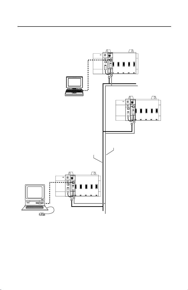
1-2 Introducing the 1747-KFC15 Module
RS-232C
Laptop PC
ControlNet
Network B
ControlNet
Network A
Desktop PC
30668-M
The KFC15 module connects to the ControlNet network from one
(channel A) or both o f it s two BNC connectors via a standar d, one-meter,
ControlNet coaxial tap. For redundant media, both connectors are used.
1747-5.34 - June 1998
Page 13
Introducing the 1747-KFC15 Module 1-3
RS-232C
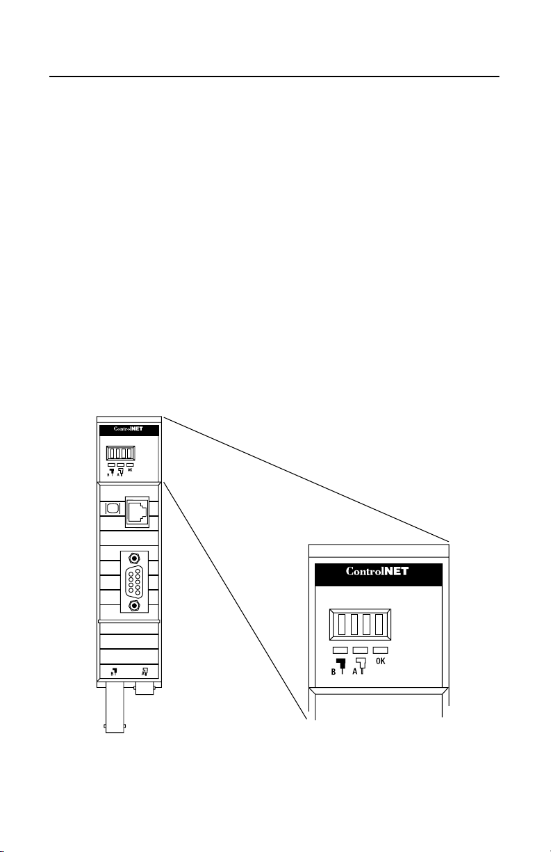
The KFC15 module has two ports for device connections:
RS-232C serial por t—provides half- or full -duplex communication wi th
a serial port on your SLC500 processor.
network access port—lets you connect a ControlNet programming
terminal or other device to the KFC15 module for full network access
without disrupting the cable wiring
The serial port uses DF1 protocol while the network access port handles
ControlNet packets directly .
Status LEDs and the dot matr ix disp lay on the fr ont of the KFC15 indica te
current operating co nditions of the unit and communication activities
taking place through the ports.
RS-232C
Display on the
1747-KFC15
module
30662-M
30665-M
1747-5.34 - June 1998
Page 14
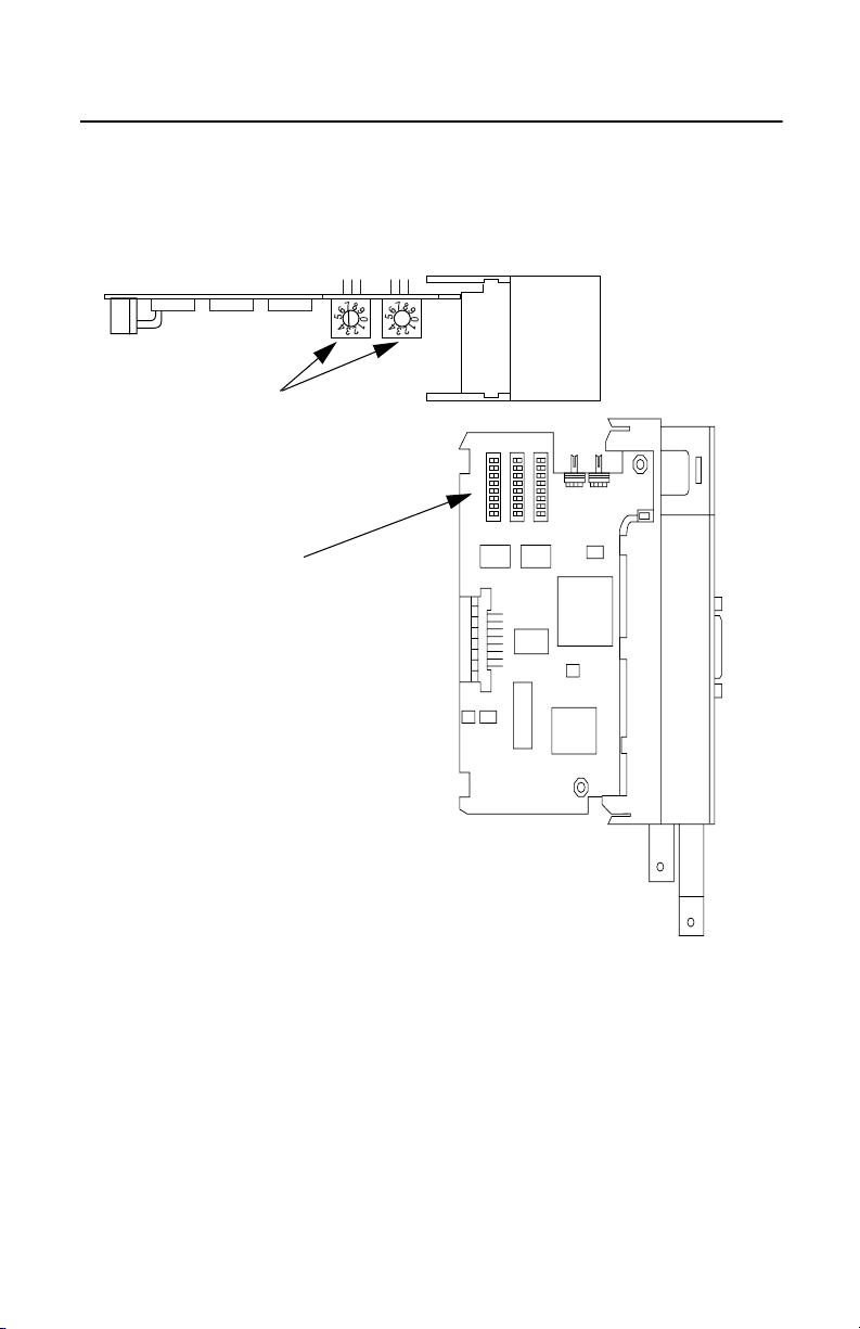
1-4 Introducing the 1747-KFC15 Module
Top View of Module
Rotary Switches
3 Banks of
DIP Switches
30663-M
30666-M
You use the three banks of DIP switches to configure the RS-232C serial
communication parameter s. Two rotary switches are available to set the
ControlNet network ad dress. To verify your settings, you can use the dot
matrix displa y located on the front of the module. Refer to Chapter 2 and
Chapter 4 for more information.
1747-5.34 - June 1998
Page 15

Introducing the 1747-KFC15 Module 1-5
Compatibility
The KFC15 is compatible with the following interfaces:
• RS-232C serial ports that comply with DF1 protocol
• ControlNet devices that comply with the ControlNet specification
• Progr amming ter minal products that comply with ControlNet
specifications for the Network Access Port
Contents of Your Order
Make sure that you have these items before you discar d any packing
material. If an item is missing or incorrect, contact your local
Allen-Bradley office.
• 1747-KFC15 module
• RS-232 cabl e
• SLC500 ControlNet RS-232 Interface User Manual
(pub. no. 1747-5.34)
1747-5.34 - June 1998
Page 16

1-6 Introducing the 1747-KFC15 Module
European Union Directive Compliance
If this product has the CE mark it is approved for installation within the
European Union and EEA regions. It has been designed a nd tested to
meet the following direct ives.
EMC Directive
This product is tested to meet Council Directive 89/336/EEC
Electromagnetic Compat ibility (EMC) and the following standards, in
whole or in part, documented in a technical construction file:
• EN 50081-2 EMC - Generic Emission Standard, Part 2 - Industrial
Environment
• EN 50082-2 EMC - Generic Immunity Standard, Part 2 - Industrial
Environment
This product is intended for use in an industrial environment.
Low Voltage Directive
This product is tested to meet Council Directive 73/23/EEC Low Voltage,
by applying the safety requir eme nts of EN 61131-2 Programmable
Controllers, Part 2 - Equipment Requirements and Tests.
For specific information required by EN 61131-2, see the appropriate
sections in this publica tion, as well as the Allen-Bradley Industr ial
Automation W iring and Grounding Guidelines For Noise Immunit y,
publication 1770-4.1.
This equipment is classif ied as open equipment and must be mounted in
an enclosure during operation to provide safety protection .
1747-5.34 - June 1998
Page 17

Introducing the 1747-KFC15 Module 1-7
CL I, DIV 2
GP A,B,C,D
TEMP
CSA Hazardous Location Approval
CSA certifies products fo r general use as well a s for use in hazardous locations. Actual CSA
certification is indicated by the product label as shown below, and not by statements in any user
documentation.
Example of the CSA certification produc t label :
To comply with CSA certification for use in hazardous lo cati ons, the
following information becomes a part of the product literature for this
CSA-certi fied industrial contro l product.
• This equipment is suitable for use in Class I, Divisio n 2, Groups A, B, C, D, or non-hazardous
locations only.
• The produ cts having the appropriate CSA markings (that is, Class I , Division 2, Groups A, B, C,
D) are certified for use in other equipment where the suitability of combination (that is, application
or use) is determined by the CSA or the local inspection office having jurisdiction.
Important: Due to the modular nature of a pro gr a mmable control s ys tem, the product with the
Temperature code rating:
highest te mperature rati ng determines the overall temper ature code rati ng of a
programmabl e con trol sy stem i n a C lass I, Divi sion 2, l ocatio n. The temperat ure co de
rating is mar ked on the product label as shown.
CL I, DIV 2
GP A,B,C,D
TEMP
Look for temperature
code rating here.
The followi ng warnings app ly to products ha ving CSA certification for use in hazar dous locations.
WARNING: Explosion hazard--
• Substitution of components may impair suitability for Class I, Division 2.
• Do not re place co m ponents unless po w er ha s be e n s w it c h ed off or the are a is know n to be non-
hazardous.
• Do not disconnect equipment unless po w e r has been switched off or the area is known t o be non-
hazardous.
• Do not d isconnect connectors unl es s power has been switched off or the area is known to be non-
hazardous. Secure any user-suppli ed connectors that mate to external circuits on this equipment
by using scre ws, sli ding latches , thread ed connec tors, or oth er means suc h that any co nnectio n can
withstand a 15 Newton (3.4 lb.) separating force applied for a minimum of one minute.
• Batteries m ust only be changed in an area known to be non-hazardou s .
CSA logo is a registered trademark of the Canadian Standards Association.
1747-5.34 - June 1998
Page 18

1-8 Introducing the 1747-KFC15 Module
C
Approbation d’utilisation dans des emplacements dangereux par la CSA
La CSA certifie les produits d'utilisation générale aussi bien que ceux qui s'utilisent dans des
emplacement s dangereux . La cer tificati on CSA en vi gueur est indiquée p ar l'ét iquette du produ it et non
par des affirmations dans la documentation à l'usage des utilisateurs.
Exemple d'étiquette de certif ica tion d'un produit par la CSA:
Pour satisfaire à la certification de la CSA dans des endroits
dangereux, les informations suivantes font partie intégrante de la
documentation ce produit industriel de contrôle certi fié par la CSA.
L I, DIV 2
GP A,B,C,D
TEMP
• Cet équipement convient à l'utilisation dans des emplacements de Classe 1, Division 2, Groupes
A, B, C, D, ou ne convient qu'à l' utilisation dans des endroits non dangereux.
• Les produi ts por tant le marqu age app ropri é de la CSA (c'est à dir e, Clas se 1, Divisi on 2, Gro upe s
A, B, C, D) sont cert ifies a l'utili sation pour d'aut res équipement s où la convenance de comb inaison
(application ou utilisation) est déterminée par la CSA ou le bureau local d'inspection qualifié.
Important: Par suite de la nature modulaire du système de contrôle programmable, le produit
Taux du code de température:
Les avertissements suivants s’appliquent aux produits ayant la certification CSA pour leur utilisation
dans des emplacements dange reux.
AVERTISSEMENT: R isque d’explosion --
ayant le taux le plus élevé de temperature déterm ine le taux d'ense mble du code de
températur e du s ys tème de contrôle d' un programmable dans un emplacement de
Classe 1, Division 2. Le taux du code de température est indiqué sur l'étiquett e du
produit.
CL I, DIV 2
GP A,B,C,D
TEMP
Le taux du code de
température est indiqué ici.
• La substitution de composants peut rendre ce matériel inacceptable pour lesemplacements de
Classe I,
Division 2.
• Couper le courant ou s'assurer quel'emplacem ent est désigné non dangereux avant de remplacer
lescomposants.
• Avant de débrancher l'équipement, couper le courant ou s'assurer que l'emplacement est dési gné
non dangereux.
• A vant de d ébrancher les con necteu rs, coup er le c ourant ou s'assur er que l'emplaceme nt est r econn u
non dang ereux . Att acher tou s co nne cteur s fo urni s p ar l' uti lisat eur et rel iés a ux ci rcui ts ext ern es d e
cet appareil à l 'aide de vis, lo quets coulissants, connecteurs filetés ou autres moyens per m ettant
aux connexions de résister à une force de séparation de 15 Newtons ( 3,4 lb. - 1,5 kg) ap pliquée
pendant au moins une minute.
• Afin d'éviter tout risq ue d'expl osion, s'as surer que l'emplace ment est dési gné non danger eux avant
de cha n ge r la ba t t erie.
Le sigle CSA est la marque déposée de l'Ass oc iation des Standards pour le Canada .
1747-5.34 - June 1998
Page 19

Chapter
2
Configuring the KFC15 Module
Use this chapter to configur e the KFC15 communica tion parameters
via the DIP switches and rotary switches on the module.
Overview of Configuration Procedures
The KFC15 module is configured by using the DIP and rotary
switches located on the module. These two types of switches
configure the RS-232 seri al communic ation parameters, and the
network address. During configuration, the module must not be
powered. Once the switches are set, the module can then be i nstalled
in the SLC chassis. Located on the front of the KFC module is a dot
matrix display, which you can use to verify your settings. Refer to
Chapter 5 for more information on the dot matrix display.
Refer to Chapter 4 for information on configuring the communicat ion
between the SLC500 and the KFC15 modules.
1747-5.34 - June 1998
Page 20

2-2 Configuring the KFC15 Module
DIP Switches
ON
1 2 3 4 5 6 7 8
The white area
indicates the position
of the switch specified
as on.
S2
S1
S3
30663-M
Located within the body of the 1747-KFC15 module are three banks (S1,
S2, and S3) of eight DIP switches. These switches are used to conf igure
the RS-232 serial communicat ion por t.
Important: The communicat ion paramet ers betwee n the SLC500 a nd the
KFC15 must be identical. Refer to Chapter 4 for more information.
Use a ball-poi nt pen to set a ny of the s witc hes withi n the th ree ba nks to on
or off.
Important: Do not use a pencil because the tip can bre ak off and short the
switch.
1747-5.34 - June 1998
Page 21

Configuring the KFC15 Module 2-3
Documented in the tables below are the DIP switches, the bank in which
they are located, and the paramete rs controlled by each switch.
Table 2-1: Bank S1 DIP Switches
DIP Switch Parameter Description
Upper digit of
Switches 1-3
Switches 4-6
Switches 7-8 Leave off
the DF1 station
addre ss
Lower digit of
DF1 station
address
SW 1/4
on
off
on
off
on
off
on
off
Table 2-2: Bank S2 DIP Switches
DIP Switch Parameters Description
Switch 1
off
off
Switches 1-3
Switch 4
Switch 5 Parity
Switch 6
Switch 7 Handshake
Switch 8
Serial Port
Baud Rate
Full/Half
duplex
Odd/Even
parity (when
used with
Switch 5)
Diagnostic
Command
Execution
off
off
on
on
on
on
off = Full duplex (default)
on = Half duplex
off = No parity (default)
on = See switch 6
off = Odd parity
on = Even parity
off = No handshake (default)
on = Hardware handshake enable
off = Disabled (default)
on = Enabled
SW 2/5
on
on
off
off
on
on
off
off
Switch 2
off
off
on
on
off
off
on
on
SW 3/6
on
on
on
on
off
off
off
off
Switch 3
off
on
off
on
off
on
off
on
Digit
0
1
2
3
4
5
6
7 (default)
Baud Rate
1200 (default)
2400
4800
9600
19200
38400
57600
Reserved
1747-5.34 - June 1998
Page 22

2-4 Configuring the KFC15 Module
Table 2-3: Bank S3 DIP Switches
DIP
Switch
Switch 1
Switch 2 Error detect
Switch
3-4
Switch
5-8
Parameter Description
Duplicate
detect
off = Duplicate detect off (default)
on = Duplicate detect on
off = CRC error check (default)
on = BCC error check
Number of
allowable
Number of
retries
retries per
attempt on the
RS-232C link:
00 - 07
The time to wait
DF1 ACK
time-out
for an ACK from
the host
computer.
SW3
on
off
on
off
SW5
on
off
on
off
on
off
on
off
on
off
on
off
on
off
on
off
SW4
on
on
off
off
SW6
on
on
off
off
on
on
off
off
on
on
off
off
on
on
off
off
Number of retries
3 (default)
SW7
SW8
on
on
on
on
on
on
on
on
off
on
off
on
off
on
off
on
on
off
on
off
on
off
on
off
off
off
off
off
off
off
off
off
0
1
2
Time
Out
.2
.4
.6
.8
1.0
1.2
1.4
1.6
1.8
2.0
2.2
2.4
2.6
2.8
3.0
3.2 (default)
1747-5.34 - June 1998
Page 23
Configuring the KFC15 Module 2-5
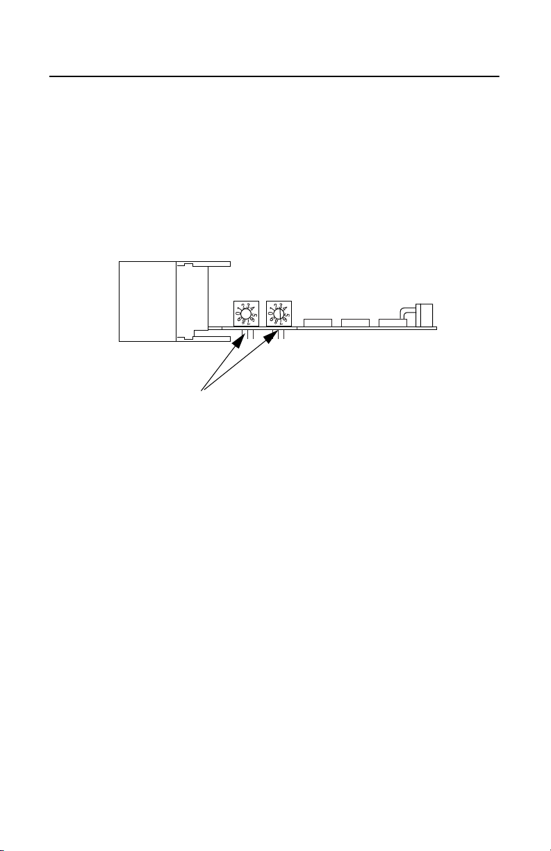
Configuring the KFC15 Module Using Rotary Switches
The KFC15’ s Control Net networ k addres s is set by the rotar y switches S4
and S5. Switch S5 sets the upper digit of the address and S4 the lower.
These switches ca n be turne d manually by hand while hol ding the module
in the orientation il lustrated below.
S5 S4
Rotary Switches S5
and S4 respectively
1747-5.34 - June 1998
Page 24

2-6 Configuring the KFC15 Module
1747-5.34 - June 1998
Page 25

Chapter
3
Installing the KFC15 Module
Use this chapter to instal l the KFC15 module. This chapter describes:
• an overvi ew of the genera l installation procedure
• how to connect the KFC15 module to your SLC500 proce ssor
through the RS-232C serial port
• how to connect the KFC15 module to a host throug h the isol ated
network access port (NAP)
• how to connect the KFC15 module to the ControlNe t network
Pinout and wiring details are provided in Appendix B, Cabling and
Pinouts. Read this if you need to construc t cables. If a tap is not
available on the ControlNe t net work for the KFC15 module, refer to
the ControlNet Cable System Planning and Installation Manual
(pub. no. 1786-6.2.1) to det ermine if your cable system can
accommodate another node and to plan where to mount the tap, then
follow the mounting instr uctions at the end of this chapter.
If you have attempted to install the KFC15 module and still have
questions, please call Rockwell Automation Technical Support at
(440) 646-6800.
1784-5.34 - June 1998
Page 26

3-2 Installing the KFC15 Module
Electrostatic Damage
ATTENTION: Electrostati c discharge can damage
semiconductor devices inside the KFC15 module. To
!
guard against electr ostatic damage wear an approved
wrist strap gr ounding devi ce, or to uch a grounded obj ect
to rid yourself of electrostatic cha rge before handli ng the
products.
Overview of the Installation Procedure
1. Configure t he communications parameters by setting the rotary and DIP
switches on the KFC15 a s detailed in Chapter 2, Configurin g the KFC15
Module. Remember tha t the R S-232 seria l communi catio n parameter s
must be the same b etween the KFC15 and the SLC500. Refer to Chapter
4 for more information.
2. Make sure that the ControlNet cabl e syst em can accommodate
additional nodes (one per KFC15 module bei ng insta lled).
3. Remove power from your SLC500 chassis.
4. Install the KFC15 module into an empty I/O slot. The 1747-KFC15
module must be placed near the SLC processor. In a large chassis, any
empty slot will not work.
5. Connect the KFC15 to the ControlNet network using taps.
1747-5.34 - June 1998
Page 27
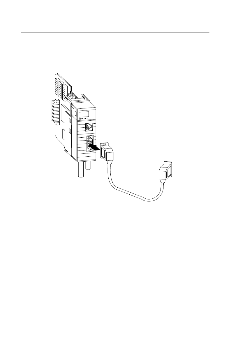
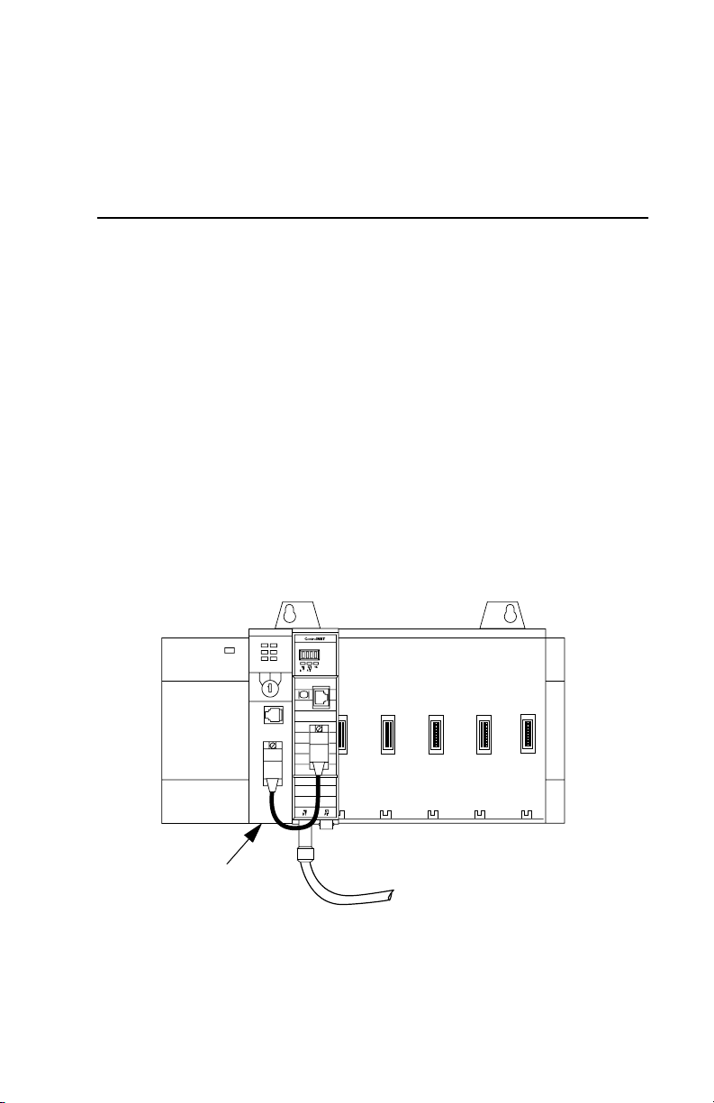
Installing the KFC15 Module 3-3
30664-M
RS-232 cable
6. Connect the KFC15 module to your SLC500 processor with the supplied
RS-232 cable.
7. Apply power to your SLC500 chassis.
Connecting a Device to the Network Access Port
Use the isolated network access port to connect a transitory device, such
as a programming device, to the KFC15 module.
Cables
You must use the Allen-Bradley Network Access cable
(cat. no. 1786-CP).
1784-5.34 - June 1998
Page 28

3-4 Installing the KFC15 Module
Connecting to the ControlNet Cable System
T o connect the KFC15 to the ControlNet cable system use an approved
ControlNet tap. Refer to the ControlNet Cable Syste m Planning and
Installation Manual (pub. no. 1786-6.2.1) for complete instructions on
connecting the tap to the cable syste m.
ATTENTION: If the KF C15 module is conne cted to a
cable system tha t does not s upport re dundant media, t he
!
tap dropline should be connecte d to the BNC connector
labeled channel A. The channel B connector should be
unused. If the cable system is redund ant, the KFC15
module should be c onnecte d su ch that a ll devices on the
network use the same cable for the same channel. The
channel A connector on all produc ts should be connected
to the same cable. The same applies for the channel B
connectors.
T o connect the KFC15 module to the tap do the following:
1. If the KFC15 module is not the last device in the segment:
• Connect the tap to the coaxial trunkli ne .
• Connect the dropline BNC to the channel A BNC of the KFC15
module.
2. If the KFC15 module is t he last device in the segment, ins tall a terminator
at the end of the cable segment, then follo w the instructions in step 1.
3. If using redundant media, repeat e ither step 1 or step 2 for channel B of
the KFC15 module.
1747-5.34 - June 1998
Page 29

Chapter
4
Communicating with the KFC15 Module
This chapter explains how to use your 1747-KFC15 module to
communicate with your SLC500 processor.
RSLinx and RSLogix500
To use your KFC15 module to communicate with your SLC500
processor, you must have RSLinx and RSLogix500 installed on your
personal computer, along with an add-on module or communica tion
card to communication between your PC and the ControlNet networ k.
Examples of add-on modules for this type of configuration are the
1784-KTCX15, 1770-KFC15, and the 1784-PCC.
1747-5.34 - June 1998
Page 30

4-2 Communicating with the KFC15 Module
Setting the Correct Options
T o communicate with your SLC500 processor, using RSLogix500,
perform the following:
1. Start RSLogix500 and choose Comms from the menu.
2. Select System Comms from the pop-up menu. A dialog box is
displayed.
1747-5.34 - June 1998
Page 31

Communicating with the KFC15 Module 4-3
3. Select the System Communications tab.
4. From the Driver field, choose the appropriate driver for the add-on
module you are using from the drop-down list that was used to co nfigure
RSLinx for communications on the ControlNet network.
5. Within the Processor Node field, enter the 1747-KFC15 ControlNet
network address displa ying on the KFC15 module. If you are unsure,
remember the network address is se t by the rota ry switches on the
KFC15 mo dule. Refer t o Cha p te r 2 for more i n form at ion .
At this point you should be able to go on-line with your SLC500
processor.
Verifying the KFC and SLC Processor Communication Parameters
Both the SLC500 and the 1747-KFC15 RS-232 serial communication
parameters need to be identical for proper communication. The default
DIP switch settings for the KFC15 are the same defaul t settings used for
the SLC500. Only if you have changed the SLC500 se ttings do you need
to modify the settings for the KFC15. Below are the steps, perfor me d in
RSLinx, to verify the parameter s between the two modules.
Determine the Serial Parameters for the SLC Processor
1. Connect a serial cable from one of the communicat ion ports on your
computer to the SLC500 processor’s serial port.
2. Start RSLinx .
3. From the menu bar choose Communications, then Configure Drivers.
4. When the dialog box appears, choose RS232 DF1 Devices from the
Available Drivers list. Click on the Add New pushbutton.
5. When the di alog box appears , select SLC-CH0/Micr o/Panelview fr om
the Device Type list.
1747-5.34 - June 1998
Page 32

4-4 Communicating with the KFC15 Module
6. Select the Auto-Configure pushbutton to obtain the serial parameters.
Once you have confirmed the communication se ttings for the SLC500,
you can use the dot matrix display on the KFC15 to verify the settings are
the same. Refer to Chapter 5 for infor mation on interpreting the display.
If you are unsure, you can check the three DIP switch banks on the
KFC15 module for the particular settings.
Related Publications
Listed below are publications you can reference for information about
RSLogix500 and RSLinx.
• Getting Results with RSNetworks for ControlNet -
pub. no. 9399-CNETGR
• Getting Resul ts with RSLogix500 with RSNetworks for ControlNet -
pub. no. 9399-RWCNPGR
• Getting Results with RSLogix500 - pub. no. 9399-RL50GR
• Getting Results with RSLinx - pub. no. 9399-WAB32GR
1747-5.34 - June 1998
Page 33

Chapter
RS-232C
5
Troubleshooting the KFC15 Module
Use this chapter to interpr et the indicators (status LEDs and dot
matrix display) on the KFC15 module to help you troubleshoot
problems.
Interpreting the Status LEDs
There are three, bi-col or (red/green) status LEDs on the top of the
KFC15 module. Two are for ControlNet, showing the physical layer
status of channels A (primary connection) and B (redundant media
connection), and one is for the KFC15 (STATUS). These indicators
can help you diagnose problems with the modul e’s installation and
operation.
RS-232C
Display on the
1747-KFC15
module
30662-M
30665-M
1747-5.34 - June 1998
Page 34

5-2 Troubleshooting the KFC15 Module
The following terms are used to describe the state of the LEDs:
solid - on continuously in the defined state
flashing - each LED alternates betwee n the two defined states (or with
OFF if only one state is defined). This only appl ies to a single LED
viewed independently of the other. If both ControlNet LEDs are flashing,
they flash together (in pha se).
railroad - both LEDs alter nate between the two de fined sta tes a t the same
time. This only applies to both ControlNet LEDs when viewed together.
The two LEDs are always in opposite states (out-of-phase).
flickering - intermittent on/off between the two states, often in an erra tic
pattern
LED State Probable Cause Recommended Action
Channels A
and B
(viewed
together)
OFF No power or reset
SOLID RED Failed unit Check network setup then cycle
power to the KFC15 module. If
the fault persists, contact your
authorized Allen-Bradley
representative or distributor.
RAILROAD RED GREEN
RAILROAD RED OFF
Self test None
Incorrect node
configuration
(duplicate node, ID,
etc.)
Check network address and
other ControlNet configuration
parameters.
1747-5.34 - June 1998
Page 35

Troubleshooting the KFC15 Module 5-3
LED State Probable Cause Recommended Action
Channel A or
B (viewed
separately)
STATUS OFF No power is applied to
OFF Channel disabled or
unused
SOLID GREEN Channel good—data is
being received and
transmitted on this
channel
FLASHING
GREEN - OFF
FLASHING RED GREEN
FLASHING RED OFF
SOLID GREEN Normal operation—the
FLASHING
GREEN
SOLID RED Critical fault—the
FLASHING RED Non-critical fault—the
Temporary errors or
device is not on-line
Bad network
configuration
Media fault or no other
nodes present on the
network
the KFC15 module
module is OK
The KFC15 is not
properly configured
KFC15 has detected an
unrecoverable fault and
must be replaced
KFC15 has detected a
recoverable fault
Program network for redundant
media if required.
None
None. Unit will correct itself.
Check network setup then cycle
power to the KFC15 module.
Check media for broken cables,
loose connector, missing
terminators, etc.
None
None
Check and change parameter
settings.
Contact your authorized AllenBradley representative or
distributor.
Reconfigure or reset the KFC15.
Interpreting the Dot Matrix Displays
Under normal conditions, the dot matrix display should be displaying the
ControlNet network addre ss as well as the ControlNet network status.
During operation , the dot matrix dis play is use d to indic ate hardware fa ult
conditions. When the STA TUS LED is solid or flashing red, the display
shows a number indicatin g the type of ha rdware f ault. The fol lowing table
gives a description of the faults.
1747-5.34 - June 1998
Page 36

5-4 Troubleshooting the KFC15 Module
This
number
1 Processor Fault A hardware fault was detected in the processor.
2 Invalid Firmware The Flash EPROM does not contain valid firmware. New
3 Firmware Checksum
4 RAM Fault The static RAM cannot be written to reliably or a parity
5 Flash EPROM Write
9 Invalid Network
10 Duplicate Network
11 Unrecoverable
Indicates this fault Meaning
This is a major fault. Return the KFC15 for servicing.
firmware must be downloaded to the unit.
A checksum error was detected in the main application
Fault
Fault
Address
Address
Firmware Error
code of the Flash EPROM.
error has occurred. Cycle power to the KFC15.
If the problem persists, return the KFC15 for servicing.
The Flash EPROM could not be programmed correctly
during download of new firmware.
This is a major fault. Return the KFC15 for servicing.
The chosen network address is greater than the highest
network address ControlNet is configured for.
There is a device on the ControlNet network with the
same address.
Failed to re-program the boot block of the Flash EPROM.
Return the KFC15 module for servicing.
If the displays show symbols other than those shown in this chapter, this
also indicate s that th e module is malfunc tioni ng. In t his case , contac t your
Allen-Bradley repre sentative.
During the power-up of the KFC15, the display shows the serial port
parameters based on the DIP switch settings. Refer to Chapter 2 for
details on these parameters.
1747-5.34 - June 1998
Page 37

Appendix
Product Specifications
RS-232C Interface
• Start Bits 1
• Data Bits 8
• Parity None, Even, Odd
• Stop Bits 1
• Baud Rates 1200, 2400, 4800,
9600,19200, 38400, 57600
• Connect or DB-9P (male)
A
• Output RS-232C
• Protoc ol Allen-Bradley DF1
• Cable Length Recommended maximum of
7.5 m (25 ft) at 57600
baud, or 15 m (50 ft) at
lower baud rates
• Cable Type Shielde d
• Ground Isola tion Opto-coupled
1747-5.34 - June 1998
Page 38

A-2 Product Specifications
ControlNet Interface
• Connect ors Standa rd BNC Connector s
• Cable RG-6 75-ohm coaxial cable
• Media Redundanc y Connection for 2 independent
coaxial cables
• Ground Isola tion Dual transformers
Network Access Port (NAP) Interface
• Connector RJ-45 8-pin, phone jack
with shield
• Ground Isola tion Opto-coupled
Physical
• Dimensions 140 cm wide x 145 cm long x
35 cm high
• W eight 217.6 g
• Mounting SLC500 chassis
Environmental
• Operating Temperature 0°C to 60°C (32°F to 140°F)
• Storage Temperature –40°C to 85°C (–40° to 1 85°F)
• Operating Humidity 5% to 95% (non-condensing)
1747-5.34 - June 1998
Page 39

Product Specifications A-3
Agency Safety Certification
• CSA Approved. Class 1, Group A, B, C or D
Division 2
• UL Listed
• C E Compliant for all application directives
1747-5.34 - June 1998
Page 40

A-4 Product Specifications
1747-5.34 - June 1998
Page 41

Appendix
B
Cabling and Pinouts
This appendix contains the pinout and wiring information required if
you need to construct cables before installing the KFC15 to a host
device.
Cabling and Pinouts for RS-232C Connection
The KFC15 RS-232C connector is a DB-9 male with the following
EIA standard pinout:
Signal I/O Pin
GND Chassis ground . Housing
TXD Transmitted data O 3
RXD Received data I 2
RTS Request to send O 7
CTS Clear to send I 8
DSR Data set ready I 6
COM Signal common . 5
DCD Data carrier detect I 1
DTR Data terminal ready O 4
1747-5.34 - June 1998
Page 42

B-2 Cabling and Pinouts
The following diagram illustrates wiring for a DB-9 cable.
9P R/A D-Shell
I
3
2
6
5
4
8
7
9
Shield
9P R/A D-Shell
I
2
3
4
5
6
7
8
9
Shield
The following diagram illustrates the handshake wiring between the
SLC500 and the KFC15.
SLC500
KFC15
TXD 3
RXD 2
RTS 7
CTS 8
GND 5
DSR 6
DCD 1
DTR 4
1747-5.34 - June 1998
Shield
2 RXD
3 TXD
8 CTS
7 RTS
5 GND
4 DTR
6 DSR
1 DCD
Page 43

Appendix
C
DF1 Diagnostic Command Support
The information in this appendix deals with DF1 communications
between the host processor and KFC15 module. The KFC15 module
interprets and responds to the following diagnostic commands from
its DF1 RS-232 serial port:
Description Command Byte Function Code (hex)
Diagnostic Loop 06 00
Diagnostic Read Counters 06 01
Diagnostic Status 06 03
Reset Diagnostic Counters 06 07
In the Comman d and Reply Format tables below, all values are in hex
and the following abbrevi ations are used:
ADDR - address of data to be read
CMD - command code
FNC - function code
STS - status code
TNS - transaction number
1747-5.34 - June 1998
Page 44

C-2 DF1 Diagnostic Command Support
Diagnostic Loop
You ca n use th is comma nd to chec k the integr ity of the tr ansmissi ons ove r
the communicati on link. The c ommand m essage transmits up to 243 by tes
of data to a node interface module. The receiving module should reply to
this command by tra nsmitting the same data back to the originating node.
Table C.1: Command Format
1 byte 1 byte 2 bytes 1 byte
CMD
06
STS TNS
FNC
00
243 bytes
max
DATA
Table C.2: Reply Format
1 byte 1 byte 2 bytes 243 bytes max
CMD
46
STS TNS DATA
Diagnostic Read Counters
This command reads the diagnostic counters from the KFC15 module.
The format of these counters is given below. The address and size fields
can have any value (but they must be included).
Table C.3: Command Format
1 byte 1 byte 2 bytes 1 byte 2 bytes 1 byte
CMD
06
STS TNS
FNC
01
ADDR
0000
SIZE
00
Table C.4: Reply Format
1 byte 1 byte 2 bytes 16 bytes
CMD
46
1747-5.34 - June 1998
STS TNS DATA
Page 45

DF1 Diagnostic Command Support C-3
Table C.5: Reply Values
1 Total DF1 packets received, low byte
2 Total DF1 packets received, high byte
3 Total DF1 packets transmitted, low byte
4 Total DF1 packets transmitted, high byte
5 Number of DF1 retries
6 Number of DF1 packets where the retry limit was exceeded
7 Number of DF1 NAKs sent
8 Number of DF1 NAKs received
9 Number of DF1 bad messages received
10 Number of RS–232C line errors
11 Total good ControlNet packets received, low byte
12 Total good ControlNet packets received, high byte
13 Total bad ControlNet packets received, low byte
14 Total bad ControlNet packets received, high byte
15 Total ControlNet packets transmitted, low byte
16 Total ControlNet packets transmitted, high byte
Diagnostic Status
This command requests a block of status information from an RS-232C
device. The reply contains the information in its DATA field. The status
information varies f rom devi ce to devi ce. The status block is shown
below.
Table C.6: Command Format
1 byte 1 byte 2 bytes 1 byte
CMD
06
STS TNS
Table C.7: Reply Format
1 byte 1 byte 2 bytes 24 bytes
CMD
46
STS TNS DATA
FNC
03
1784-5.34 - June 1998
Page 46

C-4 DF1 Diagnostic Command Support
Table C.8: Reply Values
Data Byte Description Status Reply
1 Mode/Status Byte 00 (No Modes)
Interface/Processor Type
Bits 0 – 3: Interface type
2
3 Extended Interface Type 5F (KFC15) 60 (KFCD15)
4 On-line/Off-line Mode 0 = on-line; 1 = off-line
5
6 – 16
17 – 24 Reserved for factory use only Values may vary
(E = Extended)
Bits 4 – 7: Processor type
(F = Computer)
Series/Revision
Bits 0–4:
Bits 5–7:
Bulletin Name =
ASCII
FE (Extended)
0 = Revision A
1 = Revision B, etc.
0 = Series A
1 = Series B, etc.
“1770-KFC15 ”
“1770-KFCD15 ”
Diagnostic Counter Reset
This command resets the diagnostic counters listed above.
Table C.9: Command Format
1 byte 1 byte 2 bytes 1 byte
CMD
06
1747-5.34 - June 1998
STS TNS
FNC
07
Page 47

DF1 Diagnostic Command Support C-5
Table C.10: Reply Format
1 byte 1 byte 2 bytes
CMD
46
STS TNS
1784-5.34 - June 1998
Page 48

C-6 DF1 Diagnostic Command Support
1747-5.34 - June 1998
Page 49

Index-1
A
agency safety certification A-3
C
Cabling and Pinouts B-1
Compatibility 1-5
Connecting to the ControlNet
Cable System 3-4
ControlNet interface A-2
D
DF1 1-3
commands from host C-1
DF1 diagnostic command support
C-1
diagnostic counter reset C-4
diagnostic loop C-2
diagnostic read counters C-2
diagnostic status C-3
DIP switches
Bank S1 DIP Switches 2-3
Bank S2 DIP Switches 2-3
Bank S3 DIP Switches 2-4
S1, S2, S3 2-2
dot matrix display
interpretation table 5-4
I
Installation Procedure 3-2
L
LEDs 1-3
flashing 5-2
flickering 5-2
interpreting 5-1
railroad 5-2
solid 5-2
table of 5-2
N
network access cable 3-3
network access port 1-3, 1-5, 3-
1, A-2
1786-CP 3-3
P
product specifications A-1
R
rotary switch settings 2-5
Rotary Switches
S4, S5 2-5
RS-232C serial port 1-1, 1-3, 1-4,
1-5, 3-1, A-1, B-1
connecting to host B-1
RSLinx 4-1
RSLogix500 4-1
S
SLC500 1-1, 4-1
1747-5.34-June 1998
Page 50

Index-2
1747-5.34 - June 1998
Page 51

Page 52

Rockwell Automation Support
Rockwell Automation provides technical information on the Web to assist you in
using its products. At http://support.rockwellautomation.com
technical manuals, a knowledge base of FAQs, technical and application notes,
sample code and links to software service packs, and a MySupport feature that you
can customize to make the best use of these tools.
For an additional level of technical phone support for installation, configuration,
and troubleshooting, we offer TechConnect Support programs. For more
information, contact your local distributor or Rockwell Automation representative,
or visit http://support.rockwellautomation.com
.
Installation Assistance
If you experience a problem with a hardware module within the first 24 hours of
installation, please review the information that's contained in this manual. You can
also contact a special Customer Support number for initial help in getting your
module up and running.
, you can find
United States 1.440.646.3223
Outside United
States
Monday – Friday, 8am – 5pm EST
Please contact your local Rockwell Automation representative for any
technical support issues.
New Product Satisfaction Return
Rockwell tests all of its products to ensure that they are fully operational when
shipped from the manufacturing facility. However, if your product is not
functioning, it may need to be returned.
United States Contact your distributor. You must provide a Customer Support case number
Outside United
States
Publication 1747-5.34 - June 1998 PN 955132-68
Supersedes Pub lication 1747-IN006A- US-P - February 2000 C opyright © 2007 Rockw ell Automation, Inc. A ll rights reserved. Prin ted in Singapore.
(see phone number above to obtain one) to your distributor in order to
complete the return process.
Please contact your local Rockwell Automation representative for return
procedure.
 Loading...