

Page 1
1747-DTAM
e
p
o
e
e
b
UPGRADE PROCEDURE
1. Before removal procedure is done on the DTAM, power to the panel that
it is mounted on should be disconnected. If it is not practical in your
installation to remove power on the panel to which your DTAM is
mounted, use extreme care when performing this upgrade if live parts
are present.
CAUTION: Working on and around live equipment exposes you to
increase risk of electrical shock.
Do not remove the replacement PROM from its protective package until
the current PROM has been removed from the DTAM.
2. With the back of the panel exposed, the communication/power cable
connected to the DTAM should be removed at the end that is supplying
power (SLC500 processor or Link Coupler) first. You may then remove
the cable from the top of the DTAM. If the cable is held in place by the
strain relief tab provided on the back of the DTAM enclosure, you may
have to lightly pry at the end of the tab in order to remove the cable. If
you have installed your own keyswitch thru the access port on the
backcase you will want to remove that connection.
3. Now, with access to the back of the DTAM you will need a 5/16 inch
nutdriver to remove the 4 lockwashers/nuts that hold the DTAM to the
panel. Be careful to not allow the nuts to drop onto another device if the
panel has not been powered down. There are retaining tabs on either
side of the DTAM backcase that hold the DTAM on the panel when all
four nuts have been removed. A slight pressure to both tabs will allow
the DTAM to be pulled off the panel.
4. Place the DTAM face down on a soft flat surface to prevent scratching.
Remove the 4 lockwashers/nuts that hold the back case to the front
panel assembly with a 5/16 inch nutdriver. Remove the DTAM backcase
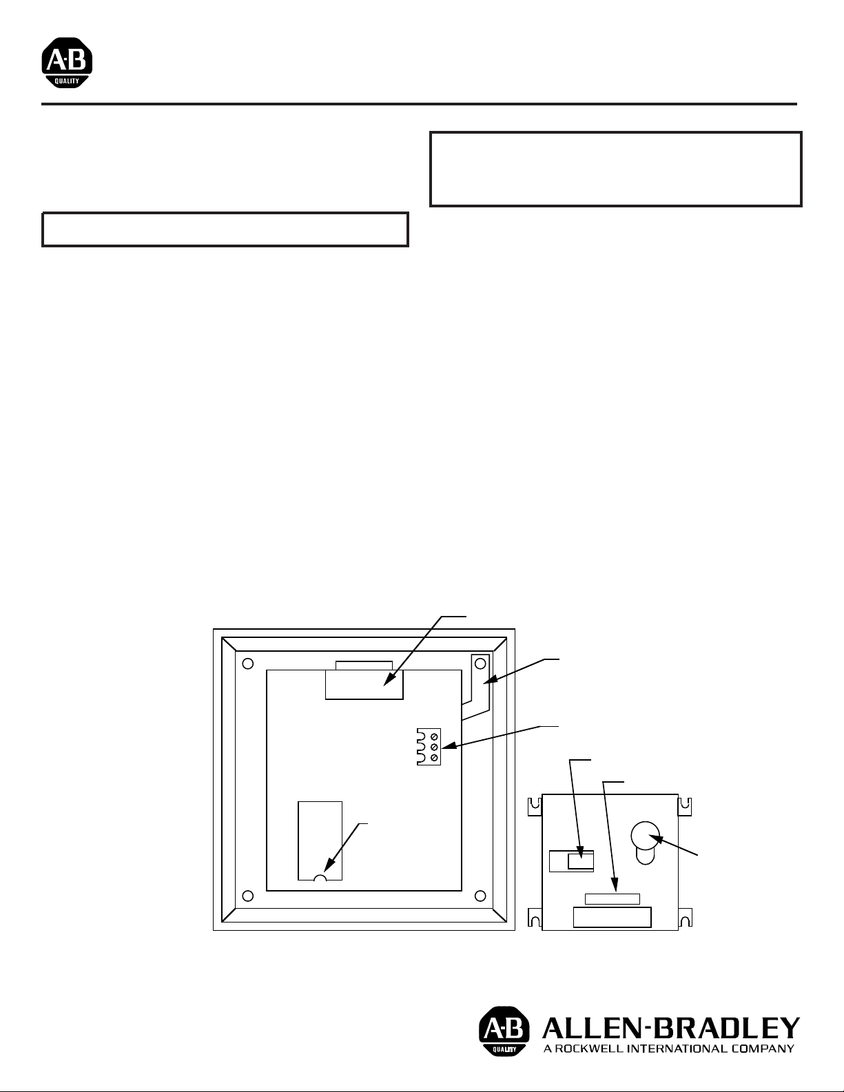
so that the socketed PROM can be viewed. See illustration 1.
CAUTION: Before proceeding, care should be taken in the removal and
insertion of the PROM. Make sure that you are electrostatically
discharged to prevent electrical damage to circuit components. Avoid
contact with the PROM leads to prevent physical damage or possible
contamination.
5. To remove the PROM from the socket use a PROM puller or
CAREFULLY pry the part out of the socket by placing a small slot-head
screwdriver between the PROM and socket. With the old PROM
removed, take the upgrade part out of the package. Place the part in
the socket with the notch facing down (see illustration 1 for correct
orientation).
6. After the upgrade PROM has been placed in the socket, powerup the
DTAM to insure that it is functioning properly. If the DTAM powers up
correctly, disconnect power and reassemble the product. The backcase
should be placed on the front panel assembly and the 4 lockwashers/
nuts torqued down to 7 inch lbs. Place the “FRN upgrade label” on the
backcase of the DTAM, while being careful not to cover any portion of
the nameplate. See illustration 1.
7. Place the DTAM back on the panel and torque down the remaining 4
lockwashers/nuts to 7 inch lbs. Connect the cable to the connector at
the top of the DTAM, and loop the cable thru the strain relieve on the
backcase if desired. If you are using an external switch rewire the
connection to the DTAM terminal block thru the back access port at the
back of the DTAM.
8. The DTAM with upgrade firmware should now be ready to operate in
your application.
Illustration 1
U103
Socketed PROM
notch facing down
U103
DTAM w/o Backcase
(Rear View)
Power / Communication P
Keypad Ground Stra
Configuration Jump
Strain Relief Ta
Add Upgrade lab
Access
Port
Nameplat
Backcase
40063-123-01 (B)
Printed in U.S.A.
 Loading...