

Page 1

Allen-Bradley
Direct
Communication
User
Module
(Cat. No. 1747-DCM)
Manual
Page 2

Important User Information
Solid state equipment has operational characteristics differing from those of
electromechanical equipment. “Safety Guidelines for the Application,
Installation and Maintenance of Solid State Controls” (Publication SGI-1.1)
describes some important differences between solid state equipment and
hard-wired electromechanical devices. Because of this difference, and also
because of the wide variety of uses for solid state equipment, all persons
responsible for applying this equipment must satisfy themselves that each
intended application of this equipment is acceptable.
In no event will the Allen-Bradley Company be responsible or liable for
indirect or consequential damages resulting from the use or application of
this equipment.
The examples and diagrams in this manual are included solely for illustrative
purposes. Because of the many variables and requirements associated with
any particular installation, the Allen-Bradley Company cannot assume
responsibility or liability for actual use based on the examples and diagrams.
No patent liability is assumed by Allen-Bradley Company with respect to use
of information, circuits, equipment, or software described in this manual.
Reproduction of the contents of this manual, in whole or in part, without
written permission of the Allen-Bradley Company is prohibited.
Throughout this manual we use notes to make you aware of safety
considerations.
ATTENTION: Identifies information about practices or
circumstances that can lead to personal injury or death, property
!
damage, or economic loss.
Attentions help you:
• identify a hazard
• avoid the hazard
• recognize the consequences
Important: Identifies information that is especially important for successful
application and understanding of the product.
PLC, PLC-2, PLC-3, and PLC-5 are registered trademarks of Allen-Bradley Company, Inc.
SLC, SLC 500, Dataliner, PanelView, RediPANEL, PLC-5/11, PLC-5/15, PLC-5/20, PLC-5/12,
PLC-5/25, PLC-5/30, PLC-5/40, PLC-5/60 are trademarks of Allen-Bradley Company, Inc.
IBM is a registered trademark of International Business Machines, Incorporated.
Page 3

Summary of Changes
Summary of Changes
The information below summarizes the changes to this manual since the last
printing as 1747-NM007–September 1993.
To help you find new information and updated information in this release of
the manual, we have included change bars as shown to the right of this
paragraph.
New Information
The table below lists sections that document new features and additional
information about existing features, and shows where to find this new
information.
For This New Information See
Related documentation updated preface
Quick Start for Experienced Users chapter 2
Default DIP switch settings chapter 4
CE certification chapter 5, appendix A
DCM clear on fault DIP switch chapter 6
Page 4

Page 5

T
able of Contents
Direct Communication Module
User Manual
Preface
Who
Should Use this Manual
Purpose
Terms
Common
Allen-Bradley
of this Manual
Contents
Related
Local
Technical Product Assistance P–5. . . . . . . . . . . . . . . . . . . . . . . . . . . . . . . .
Your Questions or Comments on this Manual P–5. . . . . . . . . . . . . . . . . . . . .
of this Manual
Documentation
and Abbreviations
Techniques Used in this Manual
Support
Product Support
P–1. . . . . . . . . . . . . . . . . . . . . . . . . . . . . . . . . . .
P–1. . . . . . . . . . . . . . . . . . . . . . . . . . . . . . . . . . . . . . . .
P–2. . . . . . . . . . . . . . . . . . . . . . . . . . . . . . . . . . . .
P–2. . . . . . . . . . . . . . . . . . . . . . . . . . . . . . . . . . . .
P–4. . . . . . . . . . . . . . . . . . . . . . . . . . . . . . . . . . . . . .
P–5. . . . . . . . . . . . . . . . . . . . . . . . . .
P–5. . . . . . . . . . . . . . . . . . . . . . . . . . . . . . . . . . . . . . . .
P–5. . . . . . . . . . . . . . . . . . . . . . . . . . . . . . . . . . . . .
Overview
Quick Start
for Experienced Users
Addressing
Chapter 1
Hardware Overview 1–1. . . . . . . . . . . . . . . . . . . . . . . . . . . . . . . . . . . . . . . . . .
System Overview 1–2. . . . . . . . . . . . . . . . . . . . . . . . . . . . . . . . . . . . . . . . . . .
What
Is a Remote I/O Adapter?
Extended
Scanner Image Division 1–4. . . . . . . . . . . . . . . . . . . . . . . . . . . . . . . . . . . . . . .
Scanner
Data Exchange Between RIO Scanners and the DCM 1–6. . . . . . . . . . . . . . . . .
What
Node Capability
Image Division Configuration Example
Is the Status W
ord? 1–6. . . . . . . . . . . . . . . . . . . . . . . . . . . . . . . . . . .
Chapter 2
Required Tools and Equipment
Procedures 2–2. . . . . . . . . . . . . . . . . . . . . . . . . . . . . . . . . . . . . . . . . . . . . . . .
Chapter 3
Addressing
PLC/Scanner Addresses 3–2. . . . . . . . . . . . . . . . . . . . . . . . . . . . . . . . . . .
SLC Addresses 3–3. . . . . . . . . . . . . . . . . . . . . . . . . . . . . . . . . . . . . . . . . .
I/O
Image
Ladder Logic Instructions
Image T
PLC to DCM/SLC 3–4. . . . . . . . . . . . . . . . . . . . . . . . . . . . . . . . . . . . . .
DCM/SLC
Mapping
ables 3–4. . . . . . . . . . . . . . . . . . . . . . . . . . . . . . . . . . . . . . . . .
to PLC
1–2. . . . . . . . . . . . . . . . . . . . . . . . . . . . . .
1–4. . . . . . . . . . . . . . . . . . . . . . . . . . . . . . . . . .
1–5. . . . . . . . . . . . . . . . . . .
2–1. . . . . . . . . . . . . . . . . . . . . . . . . . . . . . . . . .
3–1. . . . . . . . . . . . . . . . . . . . . . . . . . . . .
3–4. . . . . . . . . . . . . . . . . . . . . . . . . . . . . . . . . . . . . .
3–5. . . . . . . . . . . . . . . . . . . . . . . . . . . . . . . . . . . . . . . . . . . . .
Module Configuration
Chapter 4
DIP Switches 4–1. . . . . . . . . . . . . . . . . . . . . . . . . . . . . . . . . . . . . . . . . . . . . . .
DIP
Switch 1 Settings
Starting
Rack
DIP
Rack
Last Rack (SW2-4) 4–6. . . . . . . . . . . . . . . . . . . . . . . . . . . . . . . . . . . . . . .
Clear
Data
I/O Group Number (SW1-7 and SW1-8)
Address (SW1-1 through SW1-6)
Switch 2 Settings
Size (SW2-5 and SW2-6))
On Fault (SW2-3)
Rate (SW2-1 and SW2-2)
4–2. . . . . . . . . . . . . . . . . . . . . . . . . . . . . . . . . . . . . . . . .
4–2. . . . . . . . . . . . . . . . . . .
4–3. . . . . . . . . . . . . . . . . . . . . . . . .
4–6. . . . . . . . . . . . . . . . . . . . . . . . . . . . . . . . . . . . . . . . .
4–6. . . . . . . . . . . . . . . . . . . . . . . . . . . . . .
4–7. . . . . . . . . . . . . . . . . . . . . . . . . . . . . . . . . . . .
4–7. . . . . . . . . . . . . . . . . . . . . . . . . . . . . . .
i
Page 6

T
able of Contents
Direct Communication Module
User Manual
Installation and Wiring
Programming
Chapter 5
Compliance
EMC Directive 5–1. . . . . . . . . . . . . . . . . . . . . . . . . . . . . . . . . . . . . . . . . . .
DCM
Installation 5–2. . . . . . . . . . . . . . . . . . . . . . . . . . . . . . . . . . . . . . . . . . . . .
Removal 5–2. . . . . . . . . . . . . . . . . . . . . . . . . . . . . . . . . . . . . . . . . . . . . . .
Network
to European Union Directives
Installation
Wiring
Chapter 6
Overview 6–1. . . . . . . . . . . . . . . . . . . . . . . . . . . . . . . . . . . . . . . . . . . . . . . . .
Programming Examples 6–2. . . . . . . . . . . . . . . . . . . . . . . . . . . . . . . . . . . . . . .
Physical
Physical
Physical
Physical
Status Words 6–5. . . . . . . . . . . . . . . . . . . . . . . . . . . . . . . . . . . . . . . . . . . . . .
RIO
DCM/SLC
Applications Using I/O Status W
RIO
DCM/SLC
RIO
Input into PLC – Physical Output from SLC
Input into SLC – Physical Output from PLC
Input into Both PLC and SLC (Logical AND) –
Physical Output from SLC 6–3. . . . . . . . . . . . . . . . . . . . . . . . . . . . . . . .
Input into First SLC – Physical Output from Second SLC
Scanner Input Status W
Output Status W
Scanner Status W
Using
the Program/T
Output Status W
Using
the Data Invalid Bit
Using
the User Status Flag Bit
Scanner Input Status and DCM/SLC Output Status
Using
the Logical OR Bit
ord Examination (Decimal) 6–5. . . . . . . . . . . . .
ord Examination (Octal) 6–6. . . . . . . . . . . . . . . .
ord Bits
ord 6–7. . . . . . . . . . . . . . . . . . . . . . . . . . . . . . . . . .
est/Fault Mode Bit
ord 6–7. . . . . . . . . . . . . . . . . . . . . . . . . . . . . . .
5–1. . . . . . . . . . . . . . . . . . . . . . . . . .
5–1. . . . . . . . . . . . . . . . . . . . . . . . . . . . . . . . . . . . . . . . . . . .
5–3. . . . . . . . . . . . . . . . . . . . . . . . . . . . . . . . . . . . . . . . . . . . .
6–2. . . . . . . . . . . . . . . .
6–3. . . . . . . . . . . . . . . .
6–4. . . . . .
6–7. . . . . . . . . . . . . . . . . . . . . . . . . . . .
6–7. . . . . . . . . . . . . . . . . . . . . . .
6–7. . . . . . . . . . . . . . . . . . . . . . . . . . . . . . . . .
6–8. . . . . . . . . . . . . . . . . . . . . . . . . . . . .
6–10. . . . . . . . . . . . .
6–10. . . . . . . . . . . . . . . . . . . . . . . . . . . . . . . . .
Troubleshooting
Application Examples
ii
Chapter 7
DCM
Status Indicators
Troubleshooting
Troubleshooting Using the COMM LED (Green) 7–2. . . . . . . . . . . . . . . . . . . . . .
Using the F
AULT LED (Red) 7–1. . . . . . . . . . . . . . . . . . . . . . . .
Chapter 8
Basic Example 8–1. . . . . . . . . . . . . . . . . . . . . . . . . . . . . . . . . . . . . . . . . . . . .
1747-SN
DIP
System
System
Image
Program
Supplementary Example 8–4. . . . . . . . . . . . . . . . . . . . . . . . . . . . . . . . . . . . . .
Module
DIP
System
Image
Module Configuration
Switch Settings
Configuration for Rack 1
Configuration for Rack 2
T
able Configuration
Listing
Configuration
Switch Settings
Configuration
T
able Configuration
7–1. . . . . . . . . . . . . . . . . . . . . . . . . . . . . . . . . . . . . . . .
8–1. . . . . . . . . . . . . . . . . . . . . . . . . . . . . . .
8–2. . . . . . . . . . . . . . . . . . . . . . . . . . . . . . . . . . . . . . .
8–2. . . . . . . . . . . . . . . . . . . . . . . . . . . . . .
8–2. . . . . . . . . . . . . . . . . . . . . . . . . . . . . .
8–3. . . . . . . . . . . . . . . . . . . . . . . . . . . . . . . . . .
8–3. . . . . . . . . . . . . . . . . . . . . . . . . . . . . . . . . . . . . . . . . .
8–4. . . . . . . . . . . . . . . . . . . . . . . . . . . . . . . . . . . . . .
8–5. . . . . . . . . . . . . . . . . . . . . . . . . . . . . . . . . . . . . . .
8–5. . . . . . . . . . . . . . . . . . . . . . . . . . . . . . . . . . . . . .
8–5. . . . . . . . . . . . . . . . . . . . . . . . . . . . . . . . . .
Page 7

T
able of Contents
Direct Communication Module
User Manual
Specifications
DCM Addressing
Worksheet
Program
Program
Listing for 5/01
Listing for PLC5/15
Appendix A
Electrical
Environmental
Network
Throughput
Specifications
Specifications
Specifications
T
iming A–2. . . . . . . . . . . . . . . . . . . . . . . . . . . . . . . . . . . . . . . . . . .
Appendix B
Directions B–1. . . . . . . . . . . . . . . . . . . . . . . . . . . . . . . . . . . . . . . . . . . . . . . . .
Addressing Review B–1. . . . . . . . . . . . . . . . . . . . . . . . . . . . . . . . . . . . . . . . . .
PLC Addresses B–1. . . . . . . . . . . . . . . . . . . . . . . . . . . . . . . . . . . . . . . . . .
SLC Addresses B–1. . . . . . . . . . . . . . . . . . . . . . . . . . . . . . . . . . . . . . . . . .
8–6. . . . . . . . . . . . . . . . . . . . . . . . . . . . . . . . . . . .
8–9. . . . . . . . . . . . . . . . . . . . . . . . . . . . . . . . .
A–1. . . . . . . . . . . . . . . . . . . . . . . . . . . . . . . . . . . . . . .
A–1. . . . . . . . . . . . . . . . . . . . . . . . . . . . . . . . . . .
A–1. . . . . . . . . . . . . . . . . . . . . . . . . . . . . . . . . . . . . . . .
iii
Page 8

Page 9

Preface
Preface
Read this preface to familiarize yourself with the rest of the manual. This
preface covers the following topics:
• who should use this manual
• the purpose of this manual
• terms and abbreviations
• conventions used in this manual
• Allen–Bradley support
Who Should Use this Manual
Purpose of this Manual
Use this manual if you are responsible for designing, installing,
programming, or troubleshooting control systems that use Allen–Bradley
small logic controllers.
You should have a basic understanding of SLC 500t products. You should
understand programmable controllers and be able to interpret the ladder logic
instructions required to control your application. If you do not, contact your
local Allen–Bradley representative for information on available training
courses before using this product. If using Advanced Programming
Software (APS), we recommend that you review The APS Quick Start for
New Users, Publication 9399-APSQS.
This manual is a reference guide for the Direct Communication Module
(DCM). It describes the procedures you use to address, configure and
program the DCM for application with PLCs and SLCs.
P–1
Page 10

Preface
Contents of this Manual
Chapter Title Content
Describes the purpose, background, and scope of
Preface
1 Overview
this manual. Also specifies the audience for whom
this manual is intended.
Provides a hardware and system overview including
physical features, system communication, scanner
image division and communications flow.
2
3 Addressing Explains slot numbering and image mapping.
4 Module Configuration Provides DIP switch setting information.
5 Installation and Wiring
6 Programming
7 Troubleshooting Describes troubleshooting using front panel LEDs.
8 Application Examples
Appendix A Specifications
Appendix B DCM Addressing Worksheet
Quick Start
for Experienced Users
Serves as a Quick Start Guide for using the DCM.
Provides installation procedures and a wiring
diagram.
Shows how to program ladder logic in the PLCr
and the SLC 500, including an examination of
special programming instructions that affect system
response. Also examines the status word and its
applications.
Provides and examines both basic and
supplementary applications.
Provides module and system specifications and
discusses throughput.
Helps you to work out the image table configuration
for DCMs in your system.
P–2
Page 11

Preface
Related Documentation
The following documents contain additional information concerning
Allen–Bradley SLCt and PLC products. To obtain a copy, contact your
local Allen–Bradley office or distributor.
For Read This Document
An overview of the SLC 500 family of products SLC 500 System Overview 1747-2.30
A description on how to install and use your Fixed SLC 500
programmable controller
A description on how to install and use your Modular SLC 500
programmable controller
A reference manual that contains information regarding the use of
the PLC–5r programmable controller
A procedural manual for technical personnel who use APS to
develop control applications
A reference manual that contains status file data, and instruction
set information for the SLC 500 processors and MicroLogix 1000
controllers.
Information regarding the use of the 1747–SN SLC RIO scanner Remote I/O Scanner User Manual 1747-6.6
An introduction to APS for first–time users, containing basic
concepts but focusing on simple tasks and exercises, and allowing
the reader to begin programming in the shortest time possible
A training and quick reference guide to APS
A common procedures guide to APS.
A procedural and reference manual for technical personnel who
use an HHT to develop control applications
An introduction to HHT for first–time users, containing basic
concepts but focusing on simple tasks and exercises, and allowing
the reader to begin programming in the shortest time possible
An article on wire sizes and types for grounding electrical
equipment
A complete listing of current Allen–Bradley documentation,
including ordering instructions. Also indicates whether the
documents are available on CD–ROM or in multi–languages.
A glossary of industrial automation terms and abbreviations Allen–Bradley Industrial Automation Glossary AG-7.1
Installation & Operation Manual for Fixed Hardware
Style Programmable Controllers
Installation & Operation Manual for Modular
Hardware Style Programmable Controllers
PLC–5 Reference Instruction Set 1785-6.1
Rockwell Software Advanced Programming
Software (APS) User Manual
SLC 500t and MicroLogix 1000t Instruction Set
Reference Manual
Quick Start for New Users 9399-APSQS
SLC 500 Software Programmer’s Quick Reference
Guideavailable on PASSPORT at a list price of
$50.00
SLC 500 Common Procedures Guideavailable on
PASSPORT at a list price of $50.00
Allen–Bradley Hand–Held Terminal User Manual 1747-NP002
Getting Started Guide for HHT 1747-NM009
National Electrical Code
Allen–Bradley Publication Index SD499
Document
Number
1747-6.21
1747-6.2
9399-APSUM
1747-6.15
ABT-1747-TSG001
ABT-1747-TSJ50
Published by the
National Fire
Protection
Association of
Boston, MA.
P–3
Page 12

Preface
Terms and Abbreviations
The following terms and abbreviations are specific to this product. For a
complete listing of Allen–Bradley terminology, refer to the Allen–Bradley
Industrial Automation Glossary, Publication Number ICCG–7.1.
Adapter – Any physical device that is a slave on the RIO link.
Adapter Image – The portion of scanner image assigned to an individual
adapter. You configure the adapter image by assigning it a starting logical
rack number, starting logical group number and the number of logical groups
it uses. In the case of the DCM, this is referred to as the DCM image.
DCM – Refers to the Direct Communication Module.
Distributed Control/Controller – Refers to a control system that employs a
number of different hardware controllers/processors, each designed to
perform a different subtask on behalf of an overall program or process. In a
single processor (non–distributed) system, each task would be done by the
single processor controlling the process. In a distributed system, each task is
targeted to the specific processor required to perform its needs. Since all
processors run simultaneously and independently, the time required to
perform each task of the overall process is reduced in comparison to a single
processor system. Therefore, overall program or process performance is
typically better.
Inhibit – A function by which the scanner stops communicating with a
logical device. The logical device will consider itself inhibited if it does not
receive communications from the scanner within a certain period of time.
Logical Device
Logical Group – A logical group consists of one input and one output word
within a logical rack. A word consists of 16 bits, each bit represents one
terminal on a discrete I/O module. Also referred to as an I/O Group.
Logical Rack – A fixed section of the scanner image comprised of eight
input words and eight output words. Also referred to as a rack.
Logical Slot – A logical slot consists of one input and one output byte within
a logical group. A byte consists of 8 bits, each bit represents one terminal on
a discrete I/O module.
Physical Device – The number of devices that the supervisory processor/
scanner will support.
PLC Chassis – A physical PLC (Programmable Logic Controller) rack that
houses PLC processors and 1771 I/O modules.
– Any portion of a logical rack assigned to a single adapter.
P–4
Page 13

Preface
Rack Size – The logical rack size of the DCM image.
RIO Link – (Remote Input/Output) Refers to an Allen–Bradley
communication system supporting high–speed serial transfer of Remote I/O
(RIO) control information.
Scanner – The communication master on the RIO link.
Scanner Image – The data table area within the scanner, used to exchange
I/O information between the scanner and all the adapters on the RIO link.
The scanner image is a portion of the SLC or PLC processor image.
Slave – In a communication link, a station that cannot initiate
communication.
SLC Chassis – A physical SLC (Small Logic Controller) rack that houses
SLC processors and 1746 and 1747 I/O modules.
Slot – The physical location in any chassis used to insert I/O (or specialty)
modules.
Common Techniques Used in this Manual
Supervisory Control/Controller – A control system whereby a host
(supervisory) controller/processor monitors and intermittently adjusts control
parameters, as necessary, of one or several lower level processors while the
lower level processor(s) performs the control task continuously in real time.
The following conventions are used throughout this manual:
• Bulleted lists such as this one provide information, not procedural steps.
• Numbered lists provide sequential steps or hierarchical information.
• Italic type is used for emphasis.
P–5
Page 14

Preface
Allen–Bradley Support
Allen–Bradley offers support services worldwide, with over 75 Sales/Support
Offices, 512 authorized Distributors and 260 authorized Systems Integrators
located throughout the United States alone, plus Allen–Bradley
representatives in every major country in the world.
Local Product Support
Contact your local Allen–Bradley representative for:
• sales and order support
• product technical training
• warranty support
• support service agreements
Technical Product Assistance
If you need to contact Allen–Bradley for technical assistance, please review
the information in the Troubleshooting chapter first. Then call your local
Allen–Bradley representative.
Your Questions or Comments on this Manual
If you find a problem with this manual, please notify us of it on the enclosed
Publication Problem Report.
If you have any suggestions for how this manual could be made more useful
to you, please contact us at the address below:
Allen–Bradley Company, Inc.
Automation Group
Technical Communication, Dept. 602V, T122
P.O. Box 2086
Milwaukee, WI 53201–2086
P–6
Page 15
Chapter
are Overvie
1
Overview
This chapter provides a hardware and system overview including physical
features and connectivity illustrations. It also explains data exchange
between processors and discusses rack size. Topics include:
• hardware overview
• system overview
• scanner image division
• communications flow
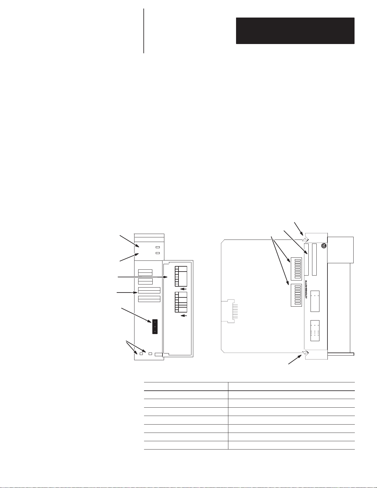
Hardw
w
FAULT LED
(Red)
COMM LED
(Green)
Door Label
Front Label
RIO Link Connector
Cable Tie Slots
The Direct Communication Module, Catalog Number 1747–DCM, is used to
connect an SLC 500 Fixed Programmable Controller with expansion chassis
or any SLC 500 Modular Programmable Controller to a supervisory
Allen–Bradley Programmable Controller via the RIO Link, thereby
providing a distributed processing system. The DCM occupies one slot in
any SLC 500 chassis.
Self–Locking Tab
Side Label
DIP Switches
DCM
FAULT
COMM
CONFIGURATION
RACK ADDR
RACK SIZE
1/4 1/2 3/4 1
FIRST I/O GROUP
0 2 4 6
DATA RATE (K B/S)
57.6 115.2 230.4
LINE 1 _______
SHIELD ______
LINE 2 _______
SW1
SW2
1747–DCM
I/O
GROUP
(LSB)
RACK
ADDRESS
2345678
(MSB)
1
O
N
X
X
RACK
SIZE
LAST
RACK
CLR ON FL
T
2345678
DATA
RATE
1
O
N
2345678
1
2345678
1
SW1 SW2
SERIAL NO.
SW 1
I/O
GROUP
(LSB)
RACK
ADDR
(MSB)
SW 2
RACK
SIZE
LAST
CLR ON FL
MADE IN USA
DATA
RATE
CAT
MODULE
X
X
RACK
T
DIRECT COMMUNICATION
SLC 500
8
7
6
5
4
3
2
1
8
7
6
5
4
3
2
1
Self–Locking Tab
Hardware Features
Hardware
Function
FAULT LED Displays operating status
COMM LED Displays communication status
Front, Side and Door Labels Provide module configuration information
RIO Link Connector Provides physical connection to RIO network
Cable Tie Slots Secure and route wiring from module
DIP Switches Establish configuration parameters for the module
Self–Locking Tabs Secure module in chassis slot
1–1
Page 16
Chapter 1
stem Overvie
Overview
Sy
w
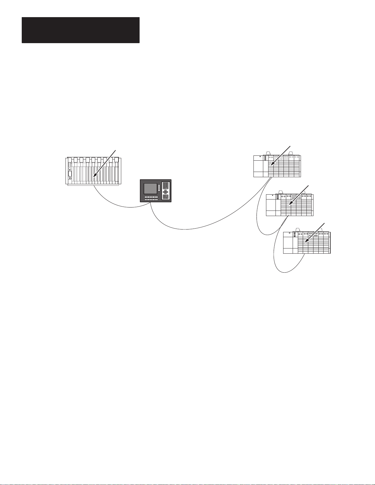
Supervisory PLC or SLC
The Direct Communication Module is an SLC 500 family Remote I/O (RIO)
adapter. It allows supervisory processors, such as PLC–5s, and distributed
SLC–500 processors residing on an Allen–Bradley RIO Communication
Link to transfer data between each other. The DCM appears as an RIO
adapter to:
• a PLC processor with integral RIO scanner on the RIO Communication
Link
• an RIO scanner, Catalog Number 1771–SN or 1747–SN, on the RIO
Communication Link
RIO
Scanner
PanelViewt
(adapter)
Distributed SLCs with
DCMs (adapters)
RIO Communication Link
DCM 1
DCM 2
DCM 3
DCM modules are connected in a daisy–chain configuration using Belden
9463 cable.
What Is a Remote I/O Adapter?
A remote I/O adapter (RIO adapter) is any module that acts as a slave to an
RIO scanner, the master on the RIO link. The DCM is an RIO adapter.
All RIO scanners have defined physical and logical specifications. Physical
specifications are the maximum number of adapters that can be connected to
the scanner. (See Extended Node Capability on page 1–4.) Logical
specifications are the maximum number of logical racks the scanner can
address, the ways logical racks can be assigned, and the ability of the scanner
to perform block transfers. Refer to the appropriate scanner manual for
details concerning physical and logical specifications.
The DCM can physically reside on the RIO link with any other adapter. The
following table lists the adapters available for use with an RIO link.
1–2
Page 17

Chapter 1
Overview
Compatible
Number
1785-LT/x PLC-5/15 Yes In adapter mode
1785-LT2 PLC-5/25 Yes In adapter mode
1785-LT3 PLC-5/12 Yes In adapter mode
1785-L30x PLC-5/30 Yes In adapter mode
1785-L40x PLC-5/40 Yes In adapter mode
1785-L60x PLC-5/60 Yes In adapter mode
1771-ASC Remote I/O Adapter Module No
1771-ASB Remote I/O Adapter Module
1771-AM1
1771-AM2
1784-F30D
1771-RIO Remote I/O Interface Module No
Catalog
Adapters
Device
1-Slot I/O Chassis with Integral
Power Supply and Adapter
2-Slot I/O Chassis with Integral
Power Supply and Adapter
Plant Floor Terminal Remote I/O
Expansion Module
Extended
Node
Capability
Series B and
C only
Yes
Yes
Yes
Comments
Series A, B, and C
1771-JAB Single Point I/O Adapter Module Yes
1771-DCM Direct Communication Module No
1778-ASB Remote I/O Adapter Module Yes
1747-ASB Remote I/O Adapter Module Yes
2706-xxxx
2705-xxx
2711-xx PanelView Terminal Yes
1336-RIO
1395-NA
1747-ASB
DL40 Datalinert
RediPANELt
Remote I/O Adapter for 1336 AC
Industrial Drives
Remote I/O Adapter for 1395 DC
Industrial Drives
SLC 500 Remote I/O Adapter
Module
Yes
Yes
Yes
Yes
Yes
Must be catalog number
2706-ExxxxxB1.
1–3
Page 18
Chapter 1
canner Image
on
Overview
Extended Node Capability
Both scanners and adapters can have extended node capability. Extended
node capability allows you to have up to 32 adapters on the RIO link using
an 82 Ohm termination resistor at both ends of the RIO link for all baud
rates.
Extended node capability can only be used if the scanner and all adapters on
the RIO link have extended node capability. The DCM has extended node
capability.
S
Divisi
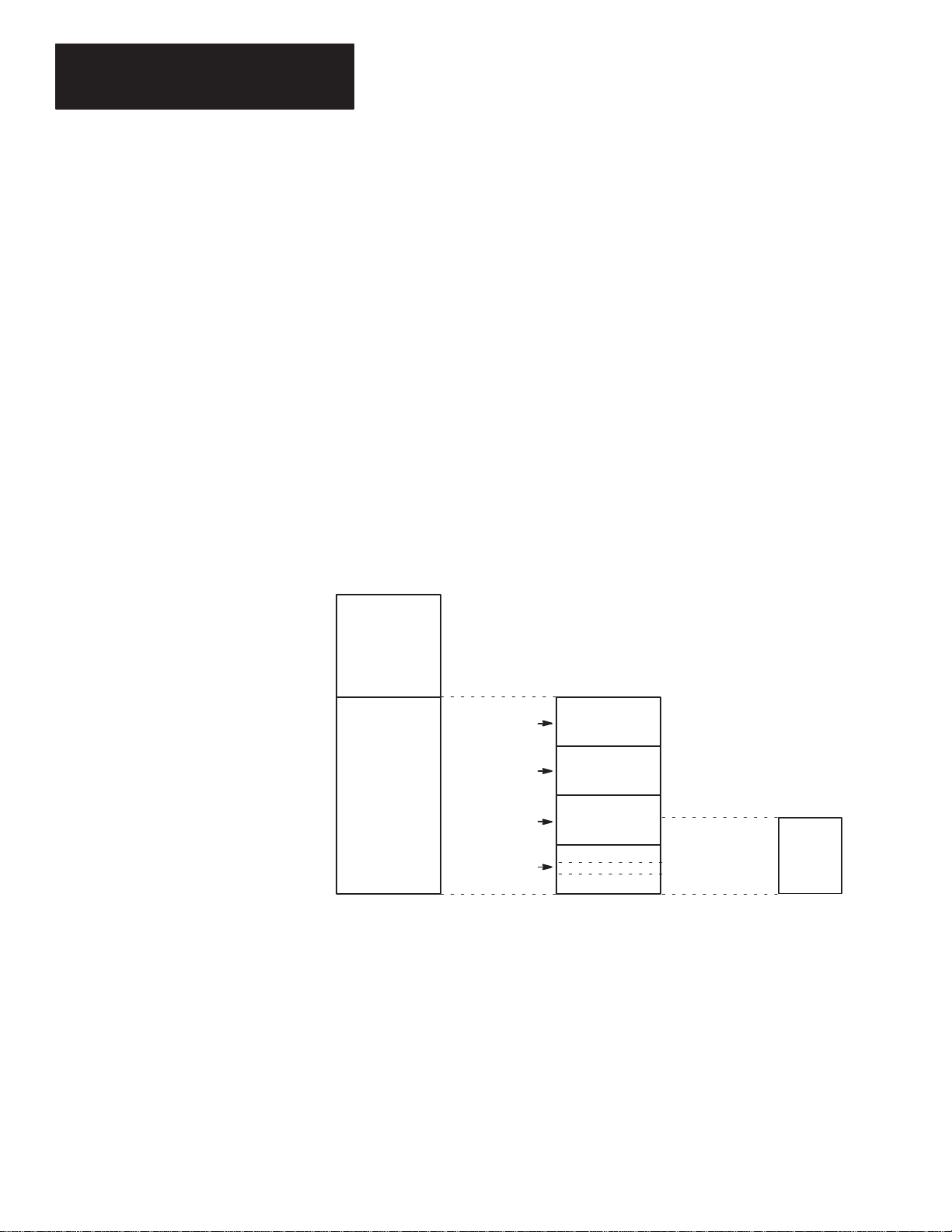
The scanner allows each adapter to use a fixed amount (user defined) of its
input and output image.
The scanner image is divided into logical racks and further divided into
logical groups. A full logical rack consists of eight input and eight output
image words. A logical group consists of one input and one output word in a
logical rack. Each logical group is assigned a number from 0–7. The
number of racks available for data and I/O transfer depends on the scanner
you are using.
Local I/O
Logical Rack 0
Remote I/O
(Scanner
Image)
Processor I/O Image Scanner I/O Image Adapter
Logical Rack 1
Logical
Rack 2
Logical Rack 3
Logical Group 0
Logical
Group 7
Image
1–4
The scanner image also contains the image of each adapter on the RIO link.
The adapter is assigned a portion of the scanner image, which is referred to
as the adapter image.
Page 19
Chapter 1
Overview
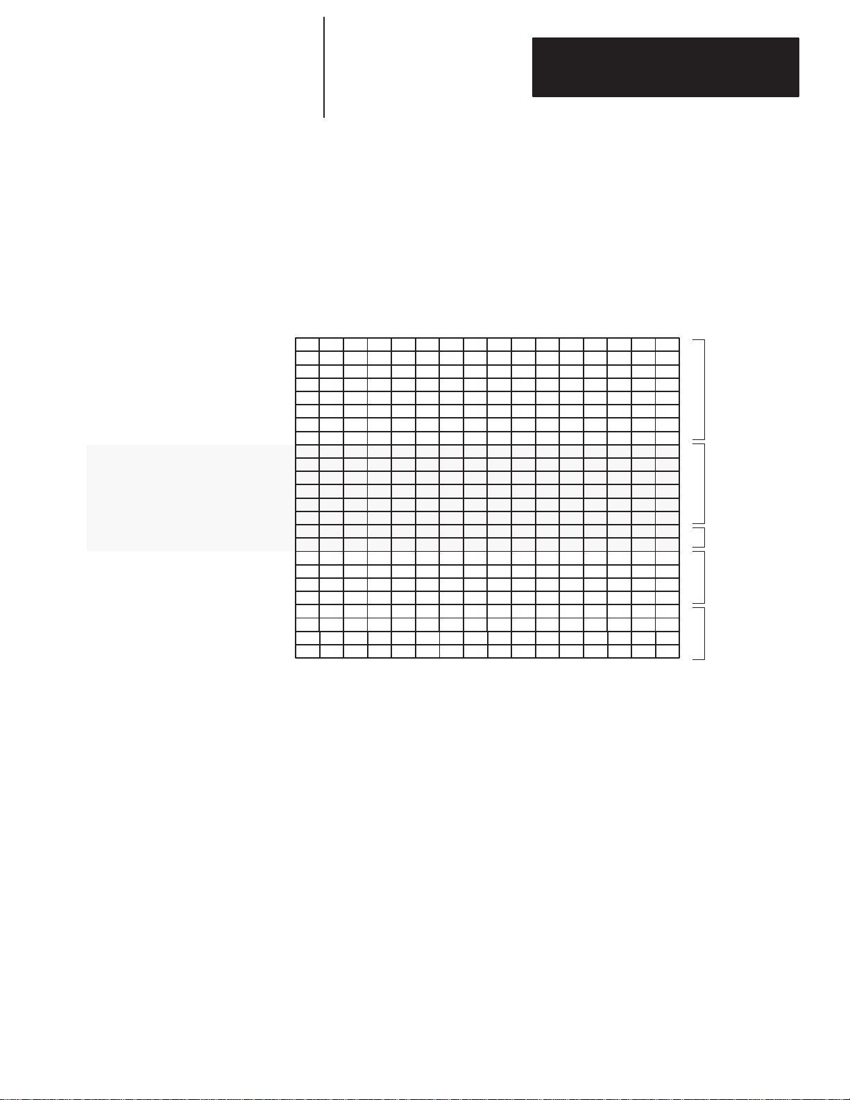
Scanner Image Division Configuration Example
The example presented here can help you configure your RIO architecture.
Refer to it as necessary.
The following figure shows how a portion of a scanner’s input image table
might be configured. An output image table would be identically configured.
Logical
0
Rack
Logical
1
Rack
Logical
Rack 2
Decimal Bit Number
Octal Bit Number
Rack 0 Group 0
Rack 0 Group 1
Rack 0 Group 2
Rack 0 Group 3
Rack 0 Group 4
Rack 0 Group 5
Rack 0 Group 6
Rack 0 Group 7
Rack 1 Group 0
Rack 1 Group 1
Rack 1 Group 2
Rack 1 Group 3
Rack 1 Group 4
Rack 1 Group 5
Rack 1 Group 6
Rack 1 Group 7
Rack 2 Group 0
Rack 2 Group 1
Rack 2 Group 2
Rack 2 Group 3
Rack 2 Group 4
Rack 2 Group 5
Rack 2 Group 6
Rack 2 Group 7
Word 0
Word 1
Word 2
Word 3
Word 4
Word 5
Word 6
Word 7
Word 8
Word 9
Word 10
Word 11
Word 12
Word 13
Word 14
Word 15
Word 16
Word 17
Word 18
Word 19
Word 20
Word 21
Word 22
Word 23
0123456789101112131415
012345671011121314151617
Device
(Full logical rack)
1
Device 2
(3/4 logical rack)
Device 3
(1/4 logical rack)
Device
Device
4
5
(1/2 logical rack)
(1/2 logical rack)
Important: The configured image size of a DCM cannot cross logical rack
boundaries; it cannot use a portion of rack 0 and a portion of
rack 1.
1–5
Page 20
Chapter 1
Overview
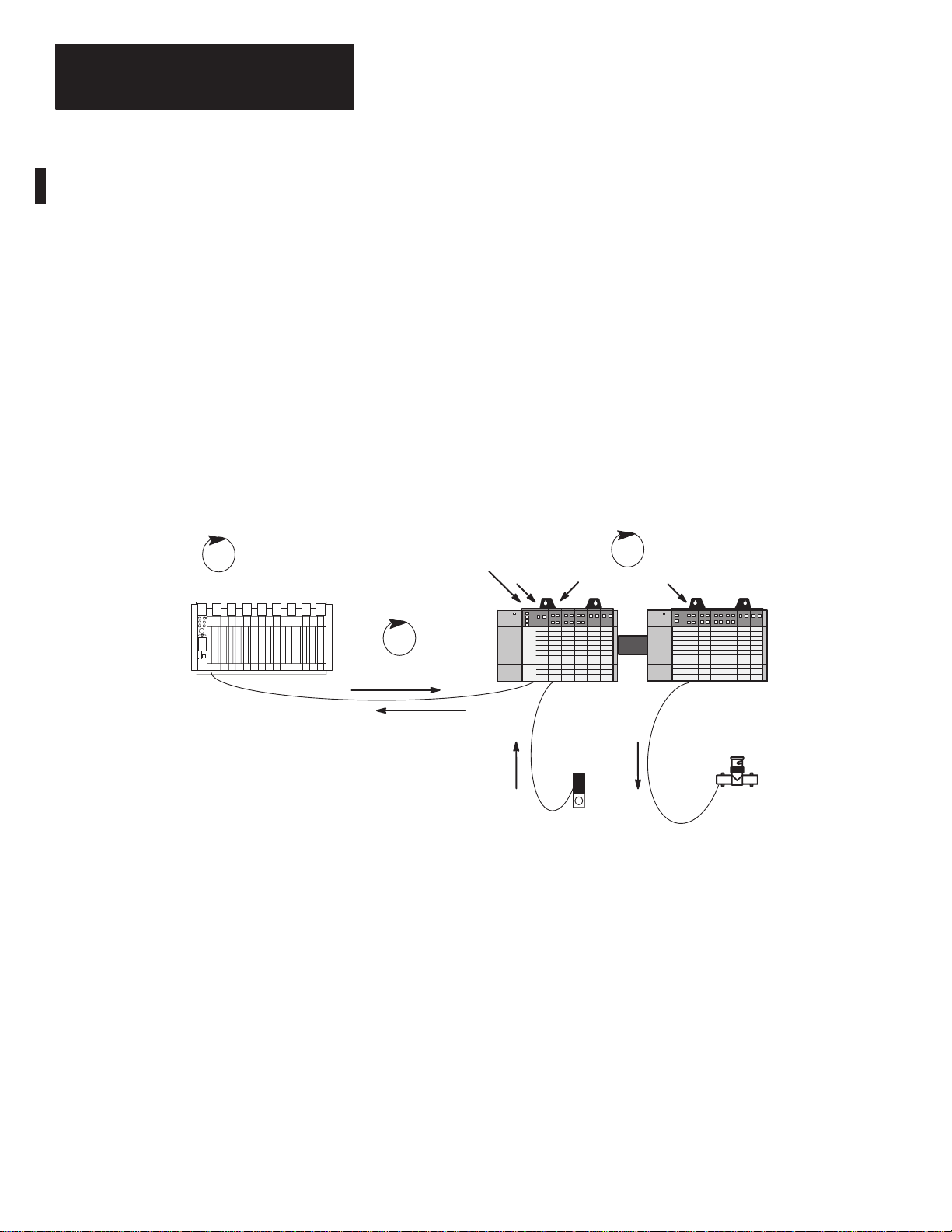
Data Exchange Between RIO Scanners and the DCM
Processor Scan
Supervisory PLC or SLC
Information is transferred between the RIO scanner and the DCM every RIO
scan. RIO transmissions are asynchronous to the processor scans.
Important: The DCM provides word integrity on all words transferred via
the SLC backplane.
The DCM communicates with supervisory PLC or SLC controllers through
RIO scanners, as if they were addressing a logical rack. However, the DCM
does not scan the I/O in its local I/O chassis, rather it passes the supervisory
data to the distributed SLC processor.
In the DCM, outputs from the SLC output image table are inputs to the
supervisory processor input image table. Likewise, outputs from the
supervisory processor output image table are inputs to the SLC input image
table.
The diagram that follows depicts the communications flow between an RIO
scanner and the DCM.
Distributed Processor Scan
SLC Distributed
Scanner
RIO Scan
Processor
DCM
I/O Module
I/O Module
Outputs from PLC,
Input Data to DCM
SLC Expansion
Chassis
Outputs from
Modules
Output Device
Inputs to PLC, Output
Data from DCM
SLC Chassis
Inputs to Modules
Input Device
What Is the Status Word?
The first word of the DCM input and output image is the status word. The
status word indicates the status of communication and data between the RIO
scanner and the DCM. For more information on status words and their
applications, see chapter 6, Programming.
1–6
Page 21

Chapter
2
Quick Start for Experienced Users
This chapter helps you to get started using the Direct Communication
Module (DCM). We base the procedures here on the assumption that you
have a basic understanding of SLC 500 products.
You must:
• understand electronic process control
• be able to interpret the ladder logic instructions for generating the
electronic signals that control your application
Because it is a start-up guide for experienced users, this chapter does not
contain detailed explanations about the procedures listed. It does, however,
reference other chapters in this book where you can get more detailed
information. It also references other documentation that may be helpful if
you are unfamiliar with programming techniques or system installation
requirements.
Required Tools and Equipment
If you have any questions, or are unfamiliar with the terms used or concepts
presented in the procedural steps, always read the referenced chapters and
other recommended documentation before trying to apply the information.
This chapter:
• tells you what tools and equipment you need
• lists preliminary considerations
• describes when to address, configure and program the module
• explains how to install and wire the module
• discusses system power-up procedures
Have the following tools and equipment ready:
• medium blade screwdriver
• (2) 1/2 watt terminating resistors (See chapter 5, Installation and Wiring,
for correct size.)
• programming equipment (All programming examples shown in this
manual demonstrate the use of Allen-Bradley’s Advanced Programming
Software [APS] for personal computers.)
2–1
Page 22

Chapter 2
Quick Start for Experienced Users
Procedures
Check
1.
the contents of the shipping box.
Unpack the module making sure that the contents include:
• Direct Communication Module (Catalog Number 1747-DCM)
• removable connector (factory-installed on module)
• cable tie
• user manual (Catalog Number 1747-NM007)
If the contents are incomplete, call your local Allen-Bradley representative for assistance.
2.
2.
Select
a scanner
.
To begin configuration of your RIO system, you should know three things:
• which scanner is compatible with your PLC/SLC controller. Use the table below to select a
scanner that is compatible with your processor. The DCM is compatible with all RIO
scanners.
Catalog Number
➀
1747-SN
➁
1771-SN
1772-SD, -SD2
➂➃
1775-S4A, -S4B, -S5
1775-SR, -SR5
1785-L11B
1785-LT/x
1785-L20B
1785-LT2
1785-L30x
1785-L40x
1785-L60x
5250-RS
6008-SI
6008-SV
➀
➀
➀➄
➀
➀➄
➀
➀
➀
➀
➀
➀
➀
SLC Remote I/O Scanner
Sub I/O scanner for Mini–PLC-2r and PLC-5 families
Remote scanner/distribution panel for PLC-2 family
I/O scanner-programmer interface module for PLC-3r family
Remote scanner/distribution panel for PLC-3/10 family
PLC 5/11t (in scanner mode)
PLC 5/15 (in scanner mode)
PLC 5/20t (in scanner mode)
PLC 5/25 (in scanner mode)
PLC 5/30t (in scanner mode)
PLC 5/40t (in scanner mode)
PLC 5/60t (in scanner mode)
Remote scanner for PLC 5/250
IBMr PC I/O Scanner Module
VMEbus I/O Scanner Module
6008-SQH1, -SQH2 Q-bus I/O Scanner Module
Description
Reference
–
Reference
The manual for
the scanner you
select
2–2
➀
Extended
➁
Revision D or later
➂
Rev
➃
Extended node capability not available with Series A.
➄
node capability
. 3 or later
.
Rev.
3 or later
PLC 5/25 Series A Revision D or later have partial rack addressing. Earlier versions are limited to 7 devices.
.PLC 5/15 Series B Revision H or later have partial rack addressing. Earlier versions are limited to 3 devices.
.
.
Page 23
Chapter 2
Quick Start for Experienced Users
• the maximum number of physical devices and logical racks your scanner supports.
• the logical rack size of each DCM. This depends on how many I/O data words you need to transfer. The first word
is always the status word. The table below shows the number of data words transferred relative to the rack size.
If you configure the DCM as:
1/4 Rack
1/2 Rack
3/4 Rack
Full Rack
3.
Select DCM addressing. (A configuration worksheet is included in appendix B to assist you in DCM
image table addressing.)
Choose
4.
Configure your system by setting the DIP switches.
5.
the type of slot addressing you will use.
Configure
Insert
the 1747-DCM module into the chassis.
1 data word (16 bits of I/O
3 data words (48 bits of I/O
5 data words (80 bits of I/O
7 data words (112 bits of I/O
the module using the DIP switches.
Then: Including the Status Word
data) are transferred.
data) are transferred.
data) are transferred.
data) are transferred.
Total transfer = 2 words
Total transfer = 4 words
Total transfer = 6 words
Total transfer = 8 words
Reference
Chapter 3
(Addressing)
Appendix B
(DCM Worksheet)
Reference
Chapter 4
(Module
Configuration)
Reference
ATTENTION: Never install, remove, or wire
modules with power applied to the chassis or
!
devices wired to the module.
SLC/DCM power requirements to ensure your SLC power supply has adequate reserve power
Review
Make sure system power is off; then insert the DCM into your 1746 chassis. In this example
procedure, local slot 1 is selected.
Module Release
Card Guide
.
.
.
Cable Tie
Chapter 5
(Installation and
Wiring)
.
2–3
Page 24

Chapter 2
Usin
xtende
8
apabilit
1
1
xtende
e
Quick Start for Experienced Users
To wire the network, a 1/2 watt terminating resistor must be attached across line 1 and line 2 of the connectors at each
end (scanner and last physical device) of the network. The size of the resistor depends on the baud rate and extended
node capability, as shown below:
Baud Rate
g E
Node C
Not Using
E
d Nod
Capability
6.
Define the application requirements. Write and enter the ladder logic program.
7.
Power up your system by performing standard start-up procedures as indicated in your processor
manual. No special start-up procedures are required when using the DCM module.
57.6K baud 3048 meters (10,000 feet)
d
115.2K baud 1524 meters (5,000 feet)
y
230.4K baud
57.6K baud 3048 meters (10,000 feet)
115.2K baud 1524 meters (5,000 feet)
230.4K baud 762 meters (2,500 feet)
Enter
Go
through the system start-up procedure.
Maximum Cable Distance
(Belden 9463)
762 meters (2,500 feet)
your ladder program.
Resistor Size
2W 1/2 Watt
Brown–Green–Brown–Gold
50W 1/2 Watt
50W 1/2 Watt
Brown–Green–Brown–Gold
82W 1/2 Watt
Gray–Red–Black–Gold
Reference
Chapter 6
(Programming)
Chapter 8
(Application
Examples)
Reference
–
2–4
Page 25

Chapter
l
3
Addressing
This chapter provides general information about how to address supervisory
PLC and distributed SLC ladder logic instructions. It also illustrates image
mapping and provides an example of how a PLC output image is mapped
into an SLC input image.
Addressing Ladder Logic Instructions
All PLC and SLC processors use 3-part addresses. These three parts include:
• logical rack or physical slot address
• logical group or word address
• bit address
PLC processors use the octal number system for bit addressing. SLC
processors use the decimal number system for bit addressing.
PLC Processors/Scanners Address By: SLC Processors Address By:
Logical Rack: PLC/scanner input and output
images are organized in logical
racks, which consist of eight
groups.
The rack address does not need to
match the SLC slot address.
Logical Group: There are eight logical groups per
logical rack, numbered 0–7. One
group consists of one input and one
output word. Each word is made
up of 16 bits.
The group number does not need
to match the SLC word address.
Bit: PLC bits are numbered octally, from
0 to 7 and 10 to 17.
Physical Slot: The slot address is determined
by what slot number you place
your DCM. SLC slots are
numbered 0–30.
The slot address does not need
to match the PLC rack address.
Word: One word is 16 bits in size. The
number of words used in input
and output images varies
according to how many you
specify in your setup. Words are
numbered consecutively
beginning with 0.
The word number does not need
to match the PLC group number.
Bit: SLC bits are numbered
decimally, from 0–15.
The bit number does not need to
match the SLC bit number
(because SLCs use decimal);
however, the position of the bit in
the word must be the same.
Octal
171615141312111076543210
Bit Number
Group 0
Group 1
Group 2
Rack
#x
Group 3
Group 4
Group 5
Group 6
Group 7
Logical
Decimal
Bit Number
Word 0
Word 1
Word 2
Word 3
Word 4
Word 5
Word 6
Word 7
The bit number does not need to
match the PLC bit number
(because PLCs use octal);
however, the position of the bit in
the word must be the same.
15 14 13 12 11 10 9 8 7 6 5 4 3 2 1 0
Physica
Slot
#x
3–1
Page 26

Chapter 3
Addressing
PLC/Scanner Addresses
The three parts of the PLC address include the:
• logical rack
• logical group (I/O group)
• bit
PLC Input
Address
PLC Output
Address
O:017/10I:023/10
I = Input
02 = Logical Rack
3 = I/O Group
10 = Bit (octal)
The rack address refers to the logical rack assigned to the DCM in the PLC/
scanner I/O image table. It is selected using switches 1 through 6 of SW1 on
the DCM. This address does not need to match the physical slot address of
the DCM. Complete information about DIP switch selection is in chapter 4,
Module Configuration.
The I/O group address refers to the word in the PLC/scanner image table
that contains the referenced I/O data bit. The I/O group address does not
need to match the word address of the SLC I/O instruction.
The bit address is the bit within the word being addressed. Bits are
numbered 0–17 (octal) for the PLC and 0–15 (decimal) for the SLC. The
physical position of the bit in the PLC word must match the position of the
bit in the SLC word to address the correct bit.
O = Output
01 = Logical Rack
7 = I/O Group
10 = Bit (octal)
3–2
Page 27

Chapter 3
Addressing
SLC Addresses
The three parts of the SLC address include the:
• physical slot
• word
• bit
SLC Input
Address
SLC Output
Address
O:1.7/8I:2.3/8
I = Input
2 = Physical Slot
3 = Word
8 = Bit (decimal)
The slot address refers to the physical slot (1–30) in the modular SLC chassis
or fixed SLC expansion chassis where the DCM is installed. This address
does not need to match the logical rack address of the PLC I/O instruction.
The word address refers to the word number (0–7) of the slot being
addressed. The maximum number of SLC I/O words that a DCM can be
assigned is 8.
The bit address is the bit within the word being addressed. Bits are
numbered 0–15 (decimal) for the SLC and 0–17 (octal) for the PLC. Outputs
from the SLC output image are inputs to the supervisory processor input
image table. Likewise, outputs from the supervisory processor output image
table are inputs to the SLC image table.
As noted, if the supervisory processor is a PLC the I/O image bits are octal
and SLC bits are decimal. While the addresses are different, the position of
the bit in the SLC word must match the position of the bit in the PLC word.
The following diagrams show this relationship.
O = Output
1 = Physical Slot
7 = Word
8 = Bit (decimal)
3–3
Page 28
Chapter 3
Addressing
I/O Image Tables
PLC to DCM/SLC
DCM/SLC configuration: Logical Rack Address = 1
Physical Slot Number = 1
Logical I/O Group = 0
Full Logical Rack
Decimal
15 14 13 12 11 10 7 6 5 4 3 2 1 098
17 16 15 14 13 12 7 6 5 4 3 2 1 011 10Octal
PLC Output Image T
Reserved for Status W
Reserved for Status W
O:011/10
O = Output
01 = Logical Rack
1 = Logical I/O Group
10 = Bit (octal)
able
ord
ord
DCM Input Image T
Decimal 15 14 13 12 11 10 7 6 5 4 3 2 1 098 Decimal 15 14 13 12 11 10 7 6 5 4 3 2 1 098
Status W
Word 0
Word 1
Word
Word 3
Word 4
Word 5
Word 6
Word 7
2
Reserved for Status W
ord
able
ord
Word 0
Word 1
Word 2
Word 3
Word 4
Word 5
Word 6
Word 7
SLC Input Image T
Status W
Reserved for Status W
I = Input
1 = Physical DCM Slot
1 = Word
8 = Bit (decimal)
DCM/SLC to PLC
DCM/SLC configuration: Logical Rack Address = 1
Physical Slot Number = 1
Logical I/O Group = 0
Full Logical Rack
ord
able
ord
I:1.1/8
Decimal
15 14 13 12 11 10 7 6 5 4 3 2 1 098
17 16 15 14 13 12 7 6 5 4 3 2 1 011 10Octal
3–4
PLC Input Image T
Status W
Reserved for Status W
I = Input
01 = Logical Rack
6 = Logical I/O Group
2 = Bit (octal)
ord
able
ord
I:016/2
DCM Output Image T
Decimal 15 14 13 12 11 10 7 6 5 4 3 2 1 098 Decimal 15 14 13 12 11 10 7 6 5 4 3 2 1 098
Status W
Word 0
Word 1
Word
Word 3
Word 4
Word 5
Word 6
Word 7
2
Reserved for Status W
ord
able
ord
Word 0
Word 1
Word 2
Word 3
Word 4
Word 5
Word 6
Word 7
SLC Output Image T
Reserved Status W
Reserved for Status W
O = Output
1 = Physical DCM Slot
6 = Word
2 = Bit (decimal)
able
ord
ord
O:1.6/2
Page 29

Chapter 3
Addressing
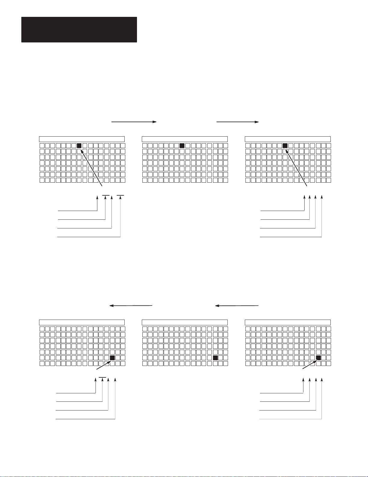
Image Mapping
An image map is a diagram showing how the scanner image is mapped into
the image of multiple adapters. The following table and illustration show
how an example PLC output image is mapped into the image of multiple
SLC processors through the DCM.
PLC Scanner Output Image To: DCM SLC Input Image
O:011/10 Starting Group 0
(Rack 01, Group 1, Bit 10 octal)
O:021/3 Starting Group 0
(Rack 02, Group 1, Bit 3 octal)
O:025/13 Starting Group 2
(Rack 02, Group 5, Bit 13 octal)
→
→
→
I:1.1/8
1
(Slot 1, Word 1, Bit 8 decimal)
I:1.1/3
2
(Slot 1, Word 1, Bit 3 decimal)
I:2.3/11
3
(Slot 2, Word 3, Bit 11 decimal)
Each row in the table represents the address of a data bit being transferred
from the PLC scanner output image to the SLC input image via three
different DCMs. The figure on the next page illustrates this data transfer.
Appendix B contains a worksheet designed to help you work out your DCM
system addressing. Use it if necessary to record I/O addresses.
3–5
Page 30

Chapter 3
Addressing
Scanner Output Image
Bit
Number:
DCM
DCM 2
DCM 3
Octal 15 14 13 12 11 10 7 6 5 4 3 2 1 0
Group 0
Group 1
Group 2
Group 3
1
Group 4
Group 5
Group 6
Group 7
Group 0
Group 1
Group 2
Group 3
Group 4
Group 5
Group
6
Group 7
17 16
10 9
13 12 11 8 7 6 5 4 3 2 1 015 14Decimal
Reserved for Status W
Reserved for Status W
Reserved for Status W
ord
ord
ord
Supervisory SLC or
PLC Processor
O:011/10
(Rack 1, Group 1, Bit 10 Octal)
O:021/2
(Rack 2, Group 1, Bit 3 Octal)
O:025/13
(Rack 2, Group 5, Bit 13 Octal)
RIO Link
Supervisory SLC or PLC
Remote I/O Scanner
SLC 1 Input Image for DCM 1
Bit
Number: Decimal
15 14 13 12 11 10 7 6 5 4 3 2 1 098
Word 0
Word 1
Word
2
Word 3
Word 4
Word 5
Word 6
Word 7
Reserved for Status W
Reserved for Status W
SLC 2 Input Image for DCM 2
Bit
Number: Decimal
15 14 13 12 11 10 7 6 5 4 3 2 1 098
Word
0
Word 1
Reserved for Status W
SLC 3 Input Image for DCM 3
Bit
Number: Decimal
15 14 13 12 11 10 7 6 5 4 3 2 1 098
Word 0
Word 1
Word 2
Word 3
Reserved for Status W
ord
ord
ord
ord
I:1.1/8
(Slot
1, Word 1, Bit 8 Decimal)
I:1.1/3
(Slot 1, Word 1, Bit 3 Decimal)
I:1.3/11
(Slot 2, W
ord 3, Bit 1
1 Decimal)
Distributed SLC
Processor 1
Distributed SLC
Processor 2
Distributed SLC
Processor 3
DCM 1
Module 1 Configured As:
Rack Address 1
Slot Number 1
DCM 2
Module 2 Configured As:
Rack Address 2
Slot Number 1
DCM 3
Module 3 Configured As:
Rack Address 2
Slot Number 2
I/O Group
Rack Size Full
I/O Group
Rack Size 1/4
I/O Group
Rack Size 1/2
0
0
2
3–6
Page 31
Chapter
4
Module Configuration
This chapter provides DIP switch setting information for the DCM. Topics
include:
• DIP switches
• DIP switch 1 settings
• DIP switch 2 settings
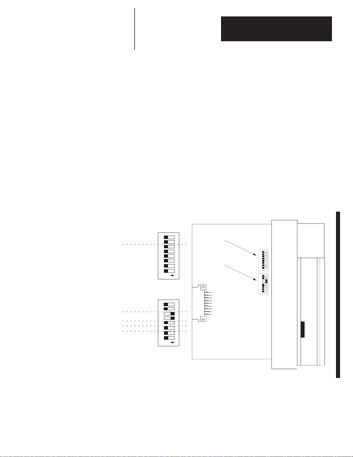
DIP Switches
To configure the DCM for your application, you must set the DIP switches.
These switches enable the DCM to properly interpret the RIO system
addressing. The DCM has two banks of DIP switches mounted on its circuit
board. Each bank contains eight switches. The default settings are shown
below.
DIP
Starting I/O Group Number
Rack Address
Reserved
Rack
Size
Last Rack
Clear On Fault
Data Rate
8
1234567
O
N
SW1
8
1234567
O
N
SW2
Switch 1
(SW1)
DIP Switch 2
(SW2)
SW1
2345678
1
234567 8
1
SW2
4–1
Page 32

Chapter 4
Module Configuration
DIP Switch 1 Settings
Starting I/O Group Number (SW1-7 and SW1-8)
The starting I/O group number is the first word assigned to the DCM from
the scanner’s image table. The starting I/O group number must be an even
number from 0 to 6 and is dependent upon whether the DCM has been
configured as a full, 3/4, 1/2, or 1/4 rack. The first word transferred is
always the status word for the DCM.
Rack Size Number of RIO Words Transferred Total Words
1/4 Logical Rack 1 Status and 1 Data 2
1/2 Logical Rack 1 Status and 3 Data 4
3/4 Logical Rack 1 Status and 5 Data 6
Full Logical Rack 1 Status and 7 Data 8
Reference the table below to set the starting I/O group number.
Starting I/O Group Number SW1-7 SW1-8 Valid Rack Configuration
0 ON ON All
2 ON OFF 3/4, 1/2, 1/4
4 OFF ON 1/2, 1/4
6 OFF OFF 1/4
Starting Group 0
Starting Group 2
Starting Group 6
Example of different starting groups:
Octal
Bit Number:
Group
Group 1, Word 1
Group 2, Word 2
Group 3, Word 3
Group 4, Word 4
Group 5, Word 5
Group 6, Word 6
Group 7, Word 7
Decimal 15 14 13 12 11 10 9 8 7 6 5 4 3 2 1 0
0, W
17 16 15 14 13 12 11 10 7 6 5 4 3 2 1 0
ord 0
RR
A SS T T U W O R D
A SS T T U W O R D
A SS T T U W O R D
In the above image map example, selecting I/O Group Number 2 instructs the scanner
to address Word 2 as the beginning of DCM 2 image. In this example, a half rack is
selected for DCM 2 (using SW2 switches 5 and 6). Since Word 2 is the first word
assigned, it becomes the Status Word.
DCM 1 Rack Size
= 1/4 Rack
DCM 2 Rack Size
= 1/2 Rack
DCM 3 Rack Size
= 1/4 Rack
4–2
Page 33

Chapter 4
Module Configuration
Rack Address (SW1-1 through SW1-6)
The rack address refers to the logical rack number from the scanner image
that contains a particular DCMs image.
The table on page 4–4 gives the switch settings that define possible rack
address choices for all scanners. To use this table, first determine which of
the following categories applies to your scanner:
• PLC-2, mini PLCs, PLC-2/30 with 1772-SD, SD2 remote scanner
• PLC-3 and PLC-5/250 processors. (This category includes those with
built-in scanners, as well as the following without built-in scanners:
catalog numbers 1775-54A, -54B, -S5, -SR, -SR5 and 5250-RS.)
• PLC-5/11, PLC-5/15, PLC-5/20, PLC-5/25, PLC-5/30, PLC-5/40, or
PLC-5/60 and 1771-SN. (This category includes all smaller in-rack
processors and standalone scanners that have local and remote I/O and
begin rack addressing at rack 1.)
• SLC-5/02 (or above) with 1747-SN scanner
After determining which category applies to your DCM application:
1. Find the column for the scanner used in your application.
2. Go down the column to the rack address that you assigned to the DCM.
3. Use the switch settings in the right-most columns of the table that
correspond to your rack address.
4–3
Page 34

Chapter 4
Module Configuration
Use this table to set SW1 – switches 1 through 6.
1747-SNPLC-2PLC-3PLC-
0 1 0 – – – – 0 ON ON ON ON ON ON
1 2 1 1 1 1 1 1 ON ON ON ON ON OFF
2 3 2 2 2 2 2 2 ON ON ON ON OFF ON
3 4 3 3 3 3 3 3 ON ON ON ON OFF OFF
5 4 4 4 4 4 ON ON ON OFF ON ON
6 5 5 5 5 5 ON ON ON OFF ON OFF
7 6 6 6 6 6 ON ON ON OFF OFF ON
Logical Rack Number (Octal) Switch Number (SW1)
7 7 7 7 7 ON ON ON OFF OFF OFF
10 10 10 10 ON ON OFF ON ON ON
11 11 11 11 ON ON OFF ON ON OFF
12 12 12 12 ON ON OFF ON OFF ON
13 13 13 13 ON ON OFF ON OFF OFF
14 14 14 14 ON ON OFF OFF ON ON
15 15 15 15 ON ON OFF OFF ON OFF
16 16 16 16 ON ON OFF OFF OFF ON
17 17 17 17 ON ON OFF OFF OFF OFF
20 20 20 ON OFF ON ON ON ON
21 21 21 ON OFF ON ON ON OFF
22 22 22 ON OFF ON ON OFF ON
23 23 23 ON OFF ON ON OFF OFF
24 24 24 ON OFF ON OFF ON ON
25 25 25 ON OFF ON OFF ON OFF
26 26 26 ON OFF ON OFF OFF ON
27 27 27 ON OFF ON OFF OFF OFF
30 30 ON OFF OFF ON ON ON
31 31 ON OFF OFF ON ON OFF
32 32 ON OFF OFF ON OFF ON
33 33 ON OFF OFF ON OFF OFF
34 34 ON OFF OFF OFF ON ON
35 35 ON OFF OFF OFF ON OFF
36 36 ON OFF OFF OFF OFF ON
37 37 ON OFF OFF OFF OFF OFF
40 OFF ON ON ON ON ON
41 OFF ON ON ON ON OFF
42 OFF ON ON ON OFF ON
43 OFF ON ON ON OFF OFF
44 OFF ON ON OFF ON ON
5/15
PLC-
5/25
PLC-
5/40
PLC-
5/60
PLC-
1 2 3 4 5 6
5/250
4–4
Continued on next page.
Page 35

Chapter 4
Module Configuration
1747-SNPLC-2PLC-3PLC-
45 OFF ON ON OFF ON OFF
46 OFF ON ON OFF OFF ON
47 OFF ON ON OFF OFF OFF
50 OFF ON OFF ON ON ON
51 OFF ON OFF ON ON OFF
52 OFF ON OFF ON OFF ON
53 OFF ON OFF ON OFF OFF
54 OFF ON OFF OFF ON ON
55 OFF ON OFF OFF ON OFF
56 OFF ON OFF OFF OFF ON
57 OFF ON OFF OFF OFF OFF
60 OFF OFF ON ON ON ON
61 OFF OFF ON ON ON OFF
62 OFF OFF ON ON OFF ON
63 OFF OFF ON ON OFF OFF
64 OFF OFF ON OFF ON ON
65 OFF OFF ON OFF ON OFF
66 OFF OFF ON OFF OFF ON
67 OFF OFF ON OFF OFF OFF
70 OFF OFF OFF ON ON ON
71 OFF OFF OFF ON ON OFF
72 OFF OFF OFF ON OFF ON
73 OFF OFF OFF ON OFF OFF
74 OFF OFF OFF OFF ON ON
75 OFF OFF OFF OFF ON OFF
76 OFF OFF OFF OFF OFF ON
77 77 77 77 77 77 77 77 Reserved
5/15
PLC-
5/25
PLC-
5/40
PLC-
5/60
PLC-
1 2 3 4 5 6
5/250
4–5
Page 36

Chapter 4
Module Configuration
DIP Switch 2 Settings
Rack Size (SW2-5 and SW2-6)
The logical rack size allocates image space in the scanner for each DCMs I/O
data. The DCM allows 1/4, 1/2, 3/4, and full rack addressing. SW2 switches
5 and 6 define the rack size.
Rack Size SW2-5 SW2-6
1/4 Logical Rack ON ON
1/2 Logical Rack ON OFF
3/4 Logical Rack OFF ON
Full Logical Rack OFF OFF
Important: The DCM image cannot cross logical rack boundaries.
Therefore, as an example, configuring the module for 1/2
logical rack with starting group 6 will cause a configuration
error. Refer to Starting I/O Group Number on page 4–2.
Last Rack (SW2-4)
Switch 4 of SW2 must be set to the OFF position if the DCM shares its
logical rack with at least one other adapter and has been assigned the highest
I/O group number in that logical rack.
Last Rack SW2-4
Yes OFF
Logical
Rack
1
SLC
Bit Number:
Module
Module 2
Module 3
Module 4
1
Octal 15 14 13 12 11 10 7 6 5 4 3 2 1 0
Group
0, W
Group 1, Word 1
Group 2, Word 2
Group 3, Word 3
Group 4, Word 4
Group 5, Word 5
Group 6, Word 6
Group 7, Word 7
ord 0
Module 4 is the last device in the logical rack.
13 12 11 10 9 8 7 6 5 4 3 2 1 015 14Decimal
17 16
No ON
Remote I/O Scanner
Output Image (to the PLC)
Because Module 4 is the last RIO adapter
in a logical rack shared by other adapter(s),
SW2 switch 4 must be in the OFF position.
Direct Communications Module 1
Module 1 Configured As:
Logical Rack Address 1
I/O Group 0
Module Rack Size 1/4
Module 2 Configured As:
Logical Rack Address 1
I/O Group 2
Module Rack Size 1/4
Module 3 Configured As:
Logical Rack Address 1
I/O Group 4
Module Rack Size 1/4
Module 4 Configured As:
Logical Rack Address 1
I/O Group 6
Module Rack Size 1/4
4–6
Page 37

Chapter 4
7
Module Configuration
Clear On Fault (SW2-3)
ATTENTION: Before setting SW2-3 to ON, make sure that
holding all DCM input bits in their last state, in the event a
communication error occurs, does not create an unsafe condition
!
in the distributed SLC processor.
Clear On Fault SW2-3
Yes OFF
No ON
Turn switch to OFF position if you want the DCM to clear and hold clear all
data bits in its input image table, in the event of an RIO communication
failure or when the supervisory processor enters Program/Test/Fault Mode.
Status bits will not be cleared.
Turn switch to ON position if you want the DCM to hold all input data bits in
their last state when an RIO communication failure occurs or when the
supervisory processor enters Program/Test/Fault Mode.
Data Rate (SW2-1 and SW2-2)
Data Rate SW2-1 SW2-2 Cable Length (Belden 9463)
57.6K baud ON ON 3048 meters (10,000 feet)
115.2K baud ON OFF 1524 meters (5,000 feet)
230.4K baud
OFF ON
62 meters (2,500 feet)
OFF OFF
4–7
Page 38

Page 39

Chapter
5
Installation and Wiring
This chapter explains how to install the DCM into the SLC chassis and
provides information about terminal wiring. Topics include:
• DCM installation
• network wiring
Compliance to European Union Directives
DCM Installation
If this product has the CE mark it is approved for installation within the
European Union and EEA regions. It has been designed and tested to meet
the following directives.
EMC Directive
This product is tested to meet Council Directive 89/336/EEC
Electromagnetic Compatibility (EMC) and the following standards, in whole
or in part, documented in a technical construction file:
• EN 50081-2
EMC – Generic Emission Standard, Part 2 – Industrial Environment
• EN 50082-2
EMC – Generic Immunity Standard, Part 2 – Industrial Environment
This product is intended for use in an industrial environment.
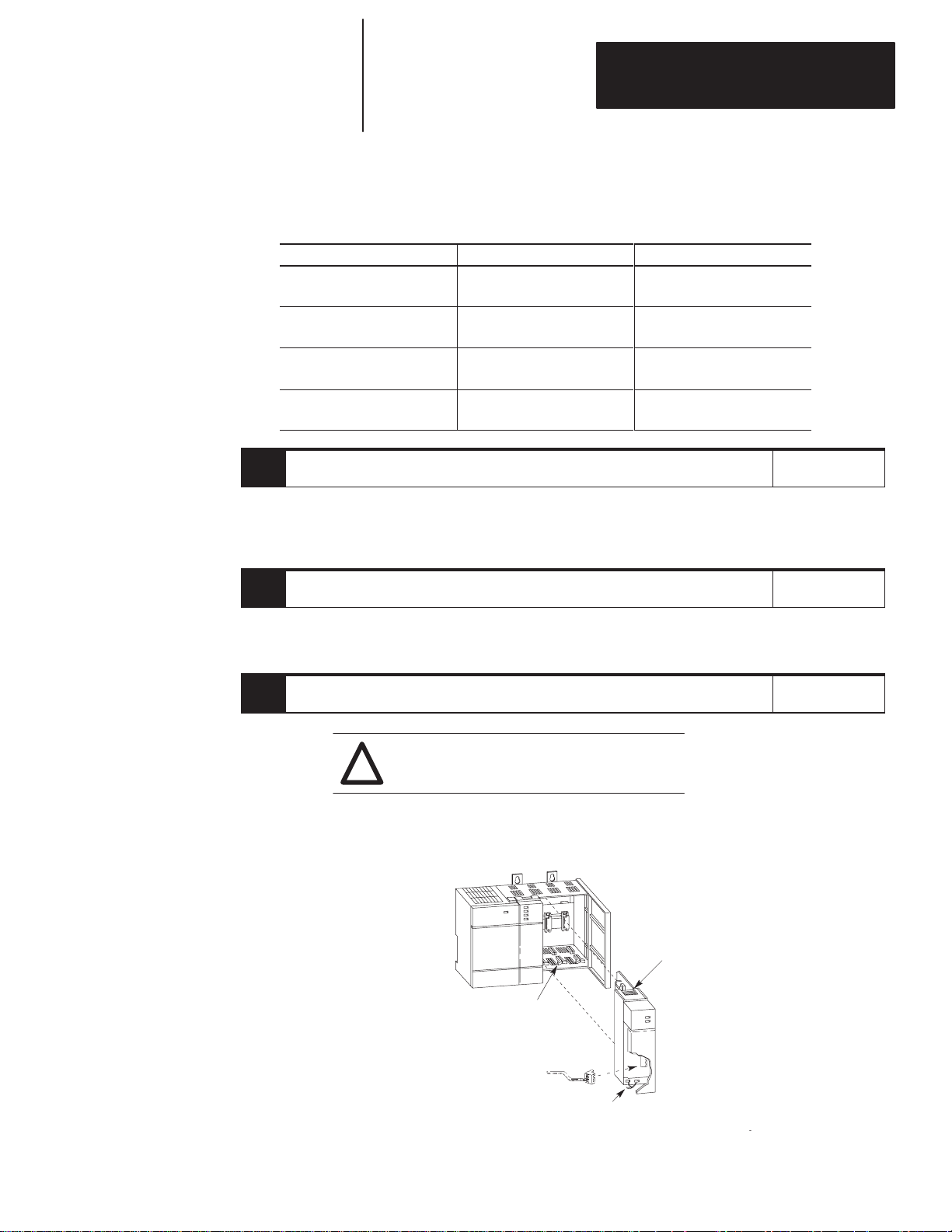
Installation procedures for this module are the same as for any other discrete
I/O or specialty module. Refer to the illustration on page 5–2 to identify
chassis and module components listed in the procedures below.
ATTENTION: Disconnect power before attempting to install,
remove, or wire the DCM.
!
Important: Make sure you have set the DIP switches properly before
installing the DCM.
Before installation make sure your modular SLC power supply
has adequate reserve current capacity. The DCM requires
360mA @ 5 volts. Each Fixed SLC 500 controller can support
up to one DCM in a 2-slot expansion chassis, depending on
which I/O module is in the second slot. Refer to the Discrete
I/O Modules Product Data, Publication Number 1746-2.35.
5–1
Page 40

Chapter 5
Installation and Wiring
Installation
1. Disconnect power.
2. Align the full-sized circuit board with the chassis card guides. The first
slot (slot 0) of the first rack is reserved for the CPU.
3. Slide the module into the chassis until the top and bottom latches are
latched.
4. Attach the RIO link cable to the connector on the front of the module
behind the door.
5. Insert the cable tie in the slots.
6. Route the cable down and away from module, securing it with the cable tie.
7. Cover all unused slots with the Card Slot Filler, Catalog Number 1746-N2.
Module Release
Card Guide
.
.
.
Cable Tie
19627
Removal
1. Disconnect power.
2. Press the releases at the top and bottom of the module and slide the
module out of the chassis slot.
3. Cover all unused slots with the Card Slot Filler, Catalog Number
1746-N2.
5–2
Page 41

Chapter 5
xten e o e
Installation and Wiring
Network Wiring
CONFIGURATION
RACK ADDR
1/4 1/2 3/4 1
RIO Link
Connector
LINE 1 _______
SHIELD ______
LINE 2 _______
Using Extended
Node Capability
Not Using
Not Using
Extended Node
Capability
DCM
FAULT
COMM
RACK SIZE
FIRST I/O GROUP
0 2 4 6
DATA RATE (K B/S)
57.6 115.2 230.4
A 1/2 watt terminating resistor must be attached across line 1 and line 2 of
the connectors at each end (scanner and last physical device) of the network.
The size of the resistor depends upon the baud rate and extended node
capability, as shown below:
Baud Rate Terminating Resistor Size
All Baud Rates
57.6K baud
115.2K baud
230.4K baud
RIO
I/O
GROUP
(LSB)
SW1
RACK
ADDRESS
2345678
(MSB)
1
O
N
X
X
RACK
SIZE
SW2
LAST
RACK
CLR ON FL
T
2345678
DATA
RATE
1
O
N
1747-DCM
Direct Communication Module
82W 1/2 Watt
150W 1/2 Watt
150W 1/2 Watt
82W 1/2 Watt
Scanner
Maximum Cable Distance
(Belden 9463)
10,000 feet at 57.6K baud
5,000 feet at 115.2K baud
2,500 feet at 230.4K baud
3048 meters (10,000 feet)
1524 meters (5,000 feet)
762 meters (2,500 feet)
Terminating
Resistor
Line 1 – Blue
Shield – Shield
Line 2 – Clear
Line 1 – Blue
Shield – Shield
Line 2 – Clear
1747–DCM
1747-DCM
Direct Communication Module
Line 1 – Blue
Shield – Shield
Line 2 – Clear
Terminating
Resistor
5–3
Page 42

Page 43

Chapter
6
Programming
This chapter shows you how to program ladder logic in the supervisory
processor/scanner and the distributed SLC to transfer data via the DCM.
Topics include:
• overview
• programming examples
• status words
• applications using status word bits
Overview
Both the supervisory processor/scanner and the distributed SLC transfer data
to and from the DCM automatically via their I/O and the RIO scan. The
DCM, as a common memory site for both supervisory and distributed
processors, has two addresses; one for the supervisory processor/
scanner and one for the SLC. The supervisory processor/scanner address is
the DCM logical rack address as set by DCM SW-1 switches 1 through 6.
The distributed SLC address is determined by the slot where the DCM is
physically installed.
The supervisory processor/scanner and distributed SLC addresses can be
different; however, the bit position part in each word must be the same.
In the programming examples on the following page, an Examine If Open
contact similar to the one shown below is used in each output rung:
I:4.0
]/[
08
This instruction checks that the Logical OR bit of the status word is false.
Whenever any of the status word bits (except the User Status Flag bit) is set,
it is indication that a condition has occurred in your logic program that may
require inspection. If this happens you would normally want to inhibit some
outputs by using a ladder logic instruction. Using an Examine If Open (XIO)
instruction examining the Logical OR bit (word 0, bit 8 for SLC; word 0, bit
10 for PLC) is the easiest way of doing this.
6–1
Page 44
Chapter 6
Programming
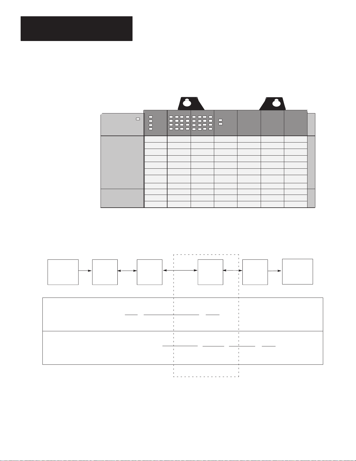
Programming Examples
The following programming examples are typical of applications using the
DCM. In each example the portion of the scanner image assigned to the
DCM is logical rack 2, starting group 0, 1 full rack, and is located in SLC
physical slot 3.
Power Supply
Physical Slot #
Output
SLC Processor
0123456
Input
DCM 1
Physical Input into PLC – Physical Output from SLC
PLC
Input Output
PLC
Processor
IN
SLC
In the example above, PLC output O:021/00 controls the (on/off) status of
DCM input I:3.1/00.
I:3.1/00 is used as a conditional ladder logic along with the Logical OR input
status bit to control SLC output O:1.0/00.
Scanner
I:000
] [
00
RIO
RIO
O:021
( )
00
I:3.1
] [
00
DCM
I:3.0
]/[
08
Logical Or Status Bit
SLC
Processor
O:1.0
( )
00
OUT
6–2
Page 45
Chapter 6
Programming
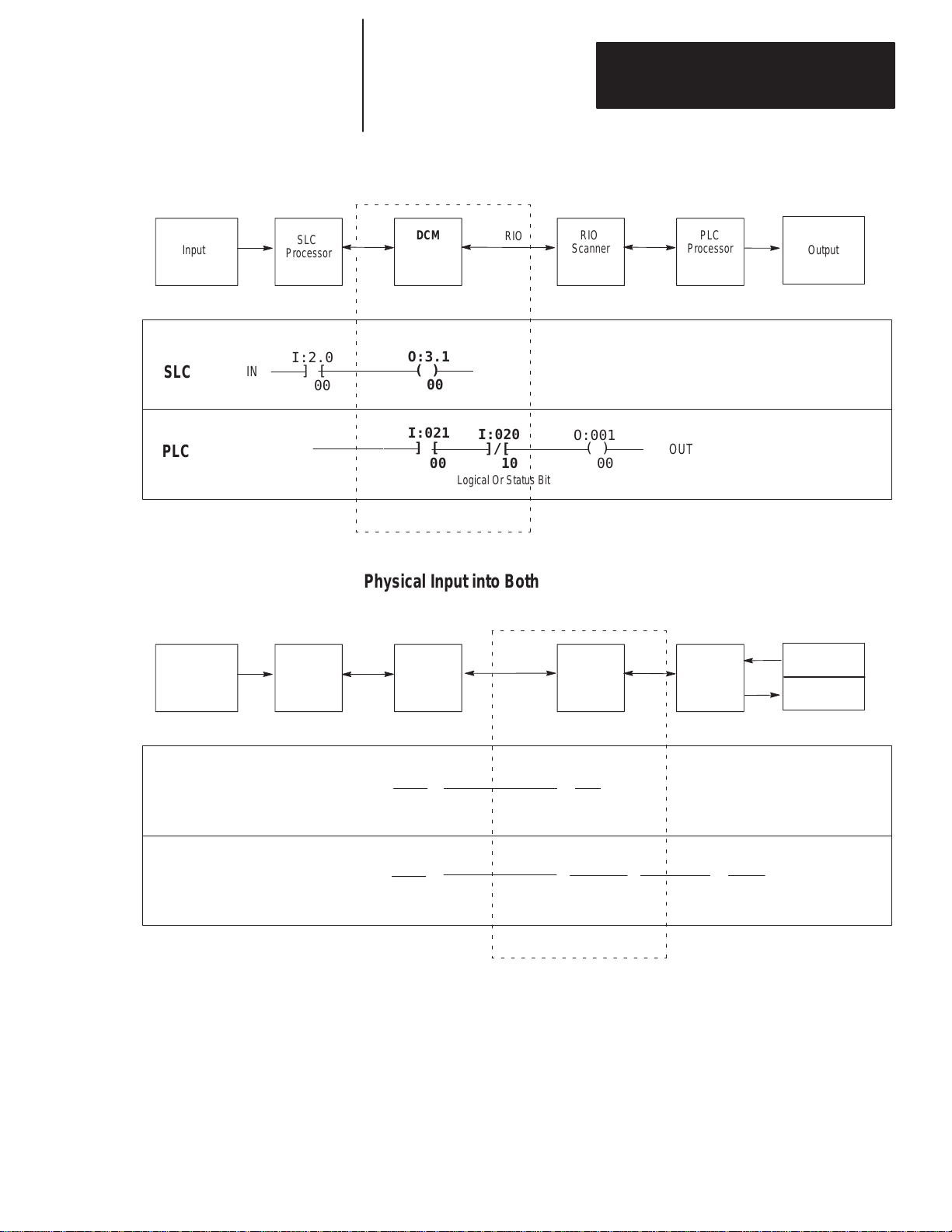
Physical Input into SLC – Physical Output from PLC
RIO
Input Output
SLC
Processor
I:2.0
SLC
IN
] [
00
DCM
O:3.1
( )
00
I:021
PLC
] [
00
Logical Or Status Bit
RIO
I:020
]/[
10
Scanner
O:001
( )
00
PLC
Processor
OUT
Physical Input into Both PLC and SLC (Logical AND) – Physical Output
from SLC
Input
PLC
Processor
RIO
Scanner
RIO
DCM
SLC
Processor
Input
Output
PLC
SLC
IN
I:000
] [
00
I:2.0
] [
00
O:021
( )
00
I:3.1
] [
00
I:3.0
]/[
08
Logical Or Status Bit
O:1.0
( )
00
OUTIN
6–3
Page 46

Chapter 6
Programming
Input
First
SLC
Processor
Physical Input into First SLC – Physical Output from Second SLC
For this example the second SLC has a logical PLC rack address of 3 and an
SLC slot address of 4.
PLC with
RIO
scanner
DCM
RIO
DCM
Second
SLC
Processor
Output
I:2.0
SLC
IN
] [
00
PLC
(No physical input into the PLC)
O:3.1
( )
00
I:021
] [
00
I:020
]/[
10
Logical Or Status Bit
I:4.1
] [
00
O:031
( )
00
I:4.0
]/[
08
Logical Or Status Bit
O:1.0
( )
00
OUT
When transmitting data from a PLC to an SLC, if the Clear On Fault (CLR
ON FLT) is active (switch is OFF), the instruction to examine the Logical
OR bit of the status word can be omitted as long as clearing the DCM input
image table puts SLC outputs into a safe state for the specific application.
6–4
Page 47

Chapter 6
Í
Í
Programming
Status Words
Bit Number: Decimal
Status Word:
Data Words:
Status Word:
Data Words:
The first word of the DCM I/O image is the status word. The status word
indicates the status of communication and data between the RIO scanner and
the DCM. Depending on what logical rack size the DCM is configured for, it
will transfer the following number of I/O words:
Rack Size Number of RIO Words Transferred Total Words
1/4 Logical Rack One (plus one Status Word) 2
1/2 Logical Rack Three (plus one Status Word) 4
3/4 Logical Rack Five (plus one Status Word) 6
Full Logical Rack Seven (plus one Status Word) 8
The figure below shows how I/O bits are transferred from the scanner to two
DCMs, each configured as a 1/2 logical rack device.
15 14 13 12 11 10 9 8 7 6 5 4 3 2 1 0
0
R
RR
R
RR
RR
RR
RRRRRRRR
DCM 1
1/2 Rack Device
RR
RRRRRRRR
DCM 2
1/2 Rack Device
Word
Word 1
Word 2
Word 3
Word 4
Word 5
Word 6
Word 7
DCM
Reserved Bits
Status Bits
R
= Reserved for future use
RIO Scanner Input Status Word Examination (Decimal)
This is the input status word sent in a data transfer from a supervisory
processor/RIO scanner to a DCM. These bits can be used as conditional
logic in your SLC program to flag DCM, RIO, or supervisory processor
system errors and/or status. Scanner status bits not defined below are
reserved for future use.
14
15
13
0
12
5
10
11
897
6
342
1
Logical OR of other Status Word bits. It is set when any
other bit is set. It is cleared when all other bits are cleared.
Program/Test/Fault Mode bit. This bit is set whenever the
supervisory processor is in the Program, Test, or Fault Mode.
DCM Initialization bit. This bit is set when the DCM is in its power-up initialization.
It will be cleared when valid data is received from the supervisory processor output
image table.
Communication Error bit. This bit is set whenever the DCM detects an RIO communication
error. It is cleared when the Communication error is cleared.
6–5
Page 48

Chapter 6
Programming
SLC
PLC
17
15
DCM/SLC Output Status Word Examination (Octal)
This is the output image status word sent in a data transfer from a DCM to a
supervisory processor/scanner. These bits can be used as conditional logic in
your supervisory processor program to flag DCM or SLC system errors
and/or status. DCM/SLC status bits not defined below are reserved for
future use.
Both the decimal and octal bit addresses are shown below to assist you in
programming your supervisory (PLC) processor and distributed SLC
processor.
0
1
0
1
16
14
15
13
14
12
11
13
10
12
897
10117
5
6
5
6
342
342
Reserved Bits
Status Bits
Logical OR of Status Word bits 11 and 12 (9 and 10 for
SLC). It is set when either 11 or 12 (9 or 10) is set. It is
cleared when 11 or 12 (9 or 10) is cleared.
Program/Test/Fault Mode bit. This bit is set whenever
the SLC controlling the DCM is in the Program, Test, or
Fault Mode.
DCM Output Data Invalid bit.➀ This bit is set when DCM output image data
could be invalid.
User Status Flag bit. This status bit is available for you to use in your application.
➀
Always use the
scanner
data being sent from the DCM to the scanner is valid. This occurs because for a brief period after the
Program/T
DCM Output Data Invalid bit
. If you use the Program/T
est/Fault mode bit is cleared the data sent from the DCM to the scanner will not be valid.
est/Fault Mode bit you may incorrectly receive an indication that the SLC
to determine the validity of SLC data sent from the DCM to the
6–6
Page 49

Chapter 6
Programming
Applications Using I/O Status Word Bits
You can use the status bits in your ladder logic to monitor various conditions
of the remote processor and the RIO network. Some examples for using the
status word bits are given here. Each of the examples shows how ladder
logic rungs could be programmed in the SLC processor to respond to the
condition of a status bit from the RIO scanner.
Important: The application examples assume the portion of the scanner
image assigned to the DCM is logical rack 2, starting group 0, 1
full rack, and is located in SLC physical slot 3.
RIO Scanner Status Word
Using the Program/Test/Fault Mode Bit
When the RIO scanner’s supervisory processor is in Program, Test, or Fault
Mode, its outputs are automatically inhibited (reset off) unless Hold Last
State is used. However, outputs sent to the DCM (DCM inputs) are not
automatically inhibited. If you want to inhibit any one SLC output
controlled by a DCM input, you can use an Examine If Open (XIO)
instruction addressed to the Program/Test/Fault Mode bit (I:3.0/9 in the
example below). This assumes an SLC output is being driven by an input
(I:3.1/0) from the scanner to the DCM, as shown below.
DCM
SLC Rung
to Monitor
RIO Scanner Status Bit 09
Conditional
I:3.1
] [
00
Input
Program/Test/Fault SLC
I:3.0
]/[
09
Status Bit
O:1.0
( )
00
Output
If you want to clear the DCM’s entire input image (data from the RIO
scanner when the RIO scanner’s supervisory processor is in Program/Test/
Fault Mode), you can set the DCM Clear On Fault DIP switch to the OFF
position. Please refer to chapter 4, Module Configuration, for more
information on this DIP switch.
DCM/SLC Output Status Word
Using the Data Invalid Bit
Whenever the distributed SLC leaves Program/Test/Fault Mode and enters
Run Mode, there is a time period after the Program/Test/Fault Mode bit is
cleared when the data sent from the DCM/SLC to the RIO scanner is invalid.
For this reason, the Program/Test/Fault Mode bit should not be used by the
RIO scanner’s supervisory processor to determine the validity of data sent
from the DCM. Instead, both processors’ programs should use the DCM
output Data Invalid bit (12 octal).
6–7
Page 50

Chapter 6
Programming
To ensure that the DCM output Data Invalid bit is cleared (signifying to the
RIO scanner’s supervisory processor that data is valid), the SLC ladder logic
rung shown below must be included as the last rung in your SLC ladder logic
program.
SLC Rung
addresses bit 10 (decimal);
RIO Scanner ’s supervisory
processor receives bit 12 (octal).
O:3.0
(U)
10
The RIO scanner’s supervisory processor ladder logic program should use
the DCM output Data Invalid bit to condition any supervisory processor
outputs whose state is dependent upon valid data from the DCM/distributed
SLC. An example of a PLC-5 processor rung that requires this conditioning
is shown below.
PLC-5 Rung
SLC addresses bit 10 (decimal);
PLC receives bit 12 (octal).
I:021
] [
00
I:020
]/[
12
O:000
( )
00
This rung uses data from the DCM (word 1, bit 0 PLC address I:021/00) to
energize a PLC-5 output: bit 0, of rack 0, module group 0. It is conditioned
with the Data Invalid bit. By using the DCM output Data Invalid bit in this
example, the PLC-5 will not energize the output shown above unless the data
received from the SLC/DCM is valid.
Using the User Status Flag Bit
This status bit (13) is available for your particular application. It is cleared
on powerup and thereafter is never operated on by the DCM. After powerup
this bit is only set (1) or cleared (0) by your SLC ladder logic program.
6–8
A typical application using this bit would be to inform the RIO scanner’s
supervisory processor that the SLC is disabling the slot where the DCM is
located. If the DCM slot is disabled while the SLC is in the Run Mode, data
sent to the RIO scanner will be last state data (invalid). Without using the
User Status Flag bit, no indication that data is not being updated would be
sent to the RIO scanner (that is, neither the Program/Test/Fault Mode bit nor
the Invalid Data bit would be set). If your SLC ladder logic program sets the
User Status Flag bit prior to disabling the DCM slot, the supervisory
processor can use this bit in its ladder logic where appropriate.
ATTENTION: Make certain that you have thoroughly examined
the effects of disabling the DCM slot before doing so in your
!
application.
An example of how rungs might be programmed in the two processors to
indicate disabling of the DCM slot is shown on the next page.
Page 51

SLC Rungs
Set User Status Flag Bit
Disable DCM
Enable DCM
Condition(s)
Condition(s)
Condition(s)
Chapter 6
Programming
➀
➀
➁
User Status Flag Bit
O:13.0
(L)
➂
11
IOM
IMMEDIATE OUT w MASK
Slot 0:3.0
Mask 0800
➃
S2:11
(U)
03
➃
S2:11
(L)
03
Clear User Status Flag Bit
➀
Condition(s) to set User Status Flag bit is the same condition(s) to disable the DCM slot. When setting the
User Status Flag bit, an Immediate I/O (IOM) instruction must be used.
➁
Condition(s) to clear User Status Flag bit is the same condition(s) to enable the DCM slot.
➂
The SLC addresses this bit as bit 1
➃
S2:11-S2:12
S2:1
1/0 represents I/O slot 0 up through S2:12/14 which represents slot 30. S2:12/15 is unused.
After programming the SLC to set and clear the User Status Flag bit, this bit
can be used to condition any PLC-5 output in this example whose state is
dependent upon the data from the distributed SLC being valid.
PLC-5 Rung
Condition(s)
➁
O:3.0
(U)
11
➂
1 (decimal); the PLC-5 receives this bit as bit 13 (octal).
– These two words are bit mapped to represent the 30 possible I/O slots in an SLC system.
I:021
] [
00
I:020
]/[
13
O:000
( )
00
The PLC-5 rung uses data from the DCM (word 1, bit 0) to energize PLC-5
output 0. It is conditioned on the User Status Flag bit being cleared. If the
SLC is programmed to set the User Status Flag bit prior to disabling the
DCM slot, the PLC-5 will never energize output 0 when data from the SLC
is invalid. For more information on how to enter PLC ladder logic, see your
PLC-5 programming manual.
6–9
Page 52

Chapter 6
Programming
RIO Scanner Input Status and DCM/SLC Output Status
Using the Logical OR Bit
Whenever any of the status word bits (except the User Status Flag bit) are
set, the Logical OR bit is set. Using an Examine If Open (XIO) instruction
examining the Logical OR bit (word 0, bit 8 for SLC; word 0, bit 10 for
PLC-5) in your ladder logic, you could inhibit any outputs or processors
when this bit is set.
SLC Rung
to Monitor
PLC-5 Status Bit 08
I:3.1
] [
00
I:3.0
]/[
08
O:1.0
( )
00
6–10
Page 53

Chapter
7
Troubleshooting
This chapter shows you how to identify and correct errors that you may
encounter using LEDs. The topics include:
• DCM status indicators
• troubleshooting using the FAULT LED (red)
• troubleshooting using the COMM LED (green)
DCM Status Indicators
Troubleshooting Using the FAULT LED (Red)
Two LEDs indicate the status of the DCM.
DCM
FAULT
COMM
If LED is: Cause: Corrective action:
On Internal Fault
Blinking Configuration Error
Off Normal State No action required.
➀
The
DCM cannot cross logical rack boundaries. Therefore, as an example, configuring the module for 1/2
logical rack with starting group 6 will cause a configuration error
Cycle power to the I/O chassis containing the DCM.
Replace DCM if red LED remains lit after powerup.
Check that the DIP switch settings are correct. Make sure
that I/O group and rack size settings are compatible.
Also see that the setting for rack address is correct. Refer
to chapter 4, Module Configuration, for help with DIP
switches.
.
Red
Green
➀
7–1
Page 54

Chapter 7
Troubleshooting
Troubleshooting Using the COMM LED (Green)
If LED is:
On Normal State No action required.
Blinking
Off
Cause: Corrective action:
RIO scanner’s processor
in Program/Test Fault
Mode
RIO scanner’s processor
not connected to scanner
RIO scanner’s processor
rack inhibited
No communication
No communication
between RIO scanner’s
processor and DCM
processor and DCM
Check for RIO scanner’s processor error, correct
condition, and cycle power to DCM.
Check that the scanner is properly installed in rack (RIO
scanner’s processor–2, #3).
Check RIO scanner’s processor rack integrity, correct any
problem, and cycle power to DCM.
Check that the baud rate of the DCM matches the baud
rate of the scanner.
Check cable connections from the RIO scanner’s
processor or scanner to the DCM.
Check that the DCM connector is properly installed.
7–2
Page 55

Chapter
8
Application Examples
This chapter provides and examines two applications of the DCM.
• basic example
• supplementary example
Basic Example
Rack 1 Rack 2
Input Switch
P2
In the following application, the 1747-DCM in the remote rack 2 will
monitor the 1747-SN data from the local rack 1. The program examples in
both local and remote rack CPUs consist of 1 rung each. When input I:1/0 is
enabled in the local rack, the output O:3.1/0 condition is transferred to the
1747-DCM input image via the 1747-SN output image. This condition
enables O:2/0 in the remote rack output card.
Output
SN
Input
SLC 5/02
1747-SN Module Configuration
RIO
(Belden 9463)
➀
P2
DCM
SLC 5/01
Output
= slot not used
Baud Rate = 57.6K baud
G-file Size = 3 words
G-File
15 14 13 12 11 10 9 8 7 6 5 4 3 2 1 0
Word 0 Reserved
Word 1 0 0 0 0 0 0 0 0 0 0 0 0 0 0 0 1 = Starting Address 0
Word 2 0 0 0 0 0 0 0 0 0 0 0 0 0 0 0 1 = 1/4 Rack Size
➀
See
SN manual for further details on configuration.
8–1
Page 56

Chapter 8
Application Examples
DCM configuration:
Rack Address = 1
I/O Group = 0
Baud Rate = 57.6K baud
Clear On Fault = no
Last Rack = no
Rack Size = 1/4
DIP Switch Settings
Switch 1 Switch 2
1 2 3 4 5 6 7 8 1 2 3 4 5 6 7 8
ON X X X X X X X X X X X X X
OFF X
System Configuration for Rack 1
Amount Device Catalog Number
1 Power Supply 1746-P2
1 SLC 5/02 Processor 1747-L524
1 4-Slot Rack 1746-A4
1 AC Input, 16 Inputs 1746-IA16
1 Relay Output, 16 Outputs 1746-OW16
1 Scanner 1747-SN
System Configuration for Rack 2
Amount Device Catalog Number
1 Power Supply 1746-P2
1 SLC 5/01 Processor 1747-L511
1 4-Slot Rack 1746-A4
= Not used
8–2
1 Relay Output, 16 Outputs 1746-OW16
1 DCM 1747-DCM
Page 57

Chapter 8
Application Examples
Image Table Configuration
Output Image
15 14 13 12 11 10 9 8 7 6 5 4 3 2 1 0
SN O:3.1/0 0 0 0 0 0 0 0 0 0 0 0 0 0 0 0 1
Input Image
15 14 13 12 11 10 9 8 7 6 5 4 3 2 1 0
DCM I:1.1/0 0 0 0 0 0 0 0 0 0 0 0 0 0 0 0 1
Program Listing
When I:1/0 is set, enabling O:3.1/0 in the SN output image, the data is sent to
the input image of the DCM I:1.1/0. The output in rack 2 is then set to
output module O:2/0.
Rack 1, Program 1
I:1
] [
0
From Input Switch To SN Output
O:3.1
Word 1, Bit 0
Rack 2, Program 2
I:1.1
] [
0
From DCM Input
Word 1, Bit 0
()
O:2
()
0
0
8–3
Page 58

Chapter 8
Application Examples
Supplementary Example
In the following application, the PLC-5/15, via its integrated RIO scanner
and the DCM, will monitor the analog data from an SLC 500. This case is
unique in that the data to be monitored is twice what the DCM can transfer.
The program in the SLC 500 will multiplex the data into four, 4-word
packets with a start and end of data word attached. The start and end of data
word is also used to designate which module the data is coming from. This
is also used by the PLC-5/15 to indicate that the data was transferred
successfully.
I/O
I/O
I/O
CPU
PLC–5
I/O
RIO
(Belden 9463)
P2
DCM
SLC 5/01
NI4
NI4
NO4I
NO4I
= slot not used
Module Configuration
PLC-5 configuration for scanner I/O status, inhibit bits:
S:27/0
=
S:27/1 = 0
S:27/2 = 1
S:27/3 = 1
* = Don’t care
DCM configuration:
Rack Address = 1
I/O Group = 0
Baud Rate = 57.6K baud
Clear on Faults = No
Last Rack = No
Rack Size = Full Rack
*
8–4
Page 59

Chapter 8
Application Examples
DIP Switch Settings
Switch 1 Switch 2
1 2 3 4 5 6 7 8 1 2 3 4 5 6 7 8
ON X X X X X X X X X X X
OFF X X X
System Configuration
Amount Device Catalog Number
1 Power Supply 1746-P2
1 SLC 5/01 Processor 1747-L511
= Not used
1 7-Slot Rack 1746-A7
2 Analog Input, 4 point 1746-NI4
2 Analog Output, 4 point 1746-NO4I
1 DCM 1747-DCM
Image Table Configuration
15 14 13 12 11 10 9 8 7 6 5 4 3 2 1 0
O:1.0 Status Word to PLC-5 from SLC
O:1.1 Counter ACC word denotes module being read
O:1.2 Word 0 of analog module being read
O:1.3 Word 1 of analog module being read
DCM
O:1.4
O:1.5 Word 3 of analog module being read
O:1.6 Counter ACC word denotes module being read
O:1.7 Not used
O:4.0 NO4I word 0
O:4.1 NO4I word 1
NO4I
O:4.2
O:4.3 NO4I word 3
O:5.0 NO4I word 0
O:5.1 NO4I word 1
NO4I
O:5.2
O:5.3 NO4I word 3
Word 2 of analog module being read
Output Image
NO4I word 2
NO4I word 2
8–5
Page 60

Chapter 8
Application Examples
Input Image
15 14 13 12 11 10 9 8 7 6 5 4 3 2 1 0
I:1.0 Status Word to SLC from PLC-5
I:1.1 Not used
I:1.2 Not used
I:1.3 Not used
DCM
I:1.4
Not used
I:1.5 Not used
I:1.6 Not used
I:1.7 Not used
I:2.0 NI4 word 0
I:2.1 NI4 word 1
NI4
I:2.2
NI4 word 2
I:2.3 NI4 word 3
I:3.0 NI4 word 0
I:3.1 NI4 word 1
NI4
I:3.2
NI4 word 2
I:3.3 NI4 word 3
Program Listing for 5/01
Processor File: MULTPLX1.ACH
Rung 0 sets the starting point of the C5:0 counter. This is done on the first scan of the program S:1/15
(first scan bit) and C5:0/DN (done bit 0) of the counter, ensuring that only the analog modules in slots 2
through 5 are read.
RUNG
2.0
C5:0
] [
DN
S:1
] [
15
Rung 1 increments the C5:0 every 5.12 seconds. The value in the ACC is referenced to the slot that the
DCM will send the data from, starting at slot 2.
S:4
RUNG
2.1
] [
8
5.12 Seconds Time Bit
MOV
MOVE
Source 2
Dest C5:0.ACC
CTU
Countup
Counter C5:0
Preset 6
Accum 0
8–6
Page 61

Chapter 8
Application Examples
For rungs 2.2 through 2.5 the module number being monitored is shown above each example. For each
rung, when SOURCE A = C5:0.ACC equals the value in SOURCE B = MODULE #, the rung moves the
module number to word 1 of the DCM output file. This verifies the start of the data and the module
number it’s coming from. Then it copies the four words of analog data to the DCM output words 2
through 5, followed by the module number at word 6 to indicate the end of data.
Module Number Monitored = 2
RUNG
2.2
RUNG
2.3
EQU
EQUAL
Source A C5:0.ACC
0
Source B 2
Module Number Monitored = 3
EQU
EQUAL
Source A C5:0.ACC
0
Source B 3
MOV
MOVE
Source C5:0.ACC
0
Dest 0:1.1
0
COP
COPY FILE
Source #I:2.0
Dest #0:1.2
Length 4
MOV
MOVE
Source C5:0.ACC
0
Dest 0:1.6
0
MOV
MOVE
Source C5:0.ACC
0
Dest 0:1.1
0
COP
COPY FILE
Source #I:3.0
Dest #0:1.2
Length 4
MOV
MOVE
Source C5:0.ACC
Dest 0:1.6
0
0
8–7
Page 62

Chapter 8
Application Examples
Module Number Monitored = 4
RUNG
2.4
RUNG
2.5
EQU
EQUAL
Source A C5:0.ACC
0
Source B 4
Module Number Monitored = 5
EQU
EQUAL
Source A C5:0.ACC
0
Source B 5
MOV
MOVE
Source C5:0.ACC
0
Dest 0:1.1
0
COP
COPY FILE
Source #I:4.0
Dest #0:1.2
Length 4
MOV
MOVE
Source C5:0.ACC
0
Dest 0:1.6
0
MOV
MOVE
Source C5:0.ACC
0
Dest 0:1.1
0
<END>
COP
COPY FILE
Source #I:5.0
Dest #0:1.2
Length 4
MOV
MOVE
Source C5:0.ACC
0
Dest 0:1.6
0
8–8
Page 63

Module Number Monitored = 2
Chapter 8
Application Examples
Program Listing for PLC5/15
The following examples are for rungs 2.0 through 2.3. The module number
being monitored is shown above the examples. For each rung, the first EQU
monitors the module number and the start of the data transfer, while the
second EQU monitors the module number and the end of the data transfer.
The COP then moves the four words of analog data to an integer file.
RUNG
2.0
RUNG
2.1
RUNG
2.2
EQU
EQUAL
Source A I:011
0
Source B 2
Module Number Monitored = 3
EQU
EQUAL
Source A I:011
0
Source B 3
Module Number Monitored = 4
EQU
EQUAL
Source A I:011
0
Source B 4
EQU
EQUAL
Source A I:016
Source B 2
EQU
EQUAL
Source A I:016
Source B 3
EQU
EQUAL
Source A I:016
Source B 4
COP
COPY FILE
Source #I:012
0
Dest #N7:0
Length 4
COP
COPY FILE
Source #I:012
0
Dest #N7:4
Length 4
COP
COPY FILE
Source #I:012
0
Dest #N7:8
Length 4
RUNG
2.3
Module Number Monitored = 5
EQU
EQUAL
Source A I:011
0
Source B 5
EQU
EQUAL
Source A I:016
Source B 5
<END>
COP
COPY FILE
Source #I:012
0
Dest #N7:12
Length 4
8–9
Page 64

Page 65

Usin
xtende
apabilit
8
1
xtende
e
Electrical Specifications
Appendix
A
Specifications
This appendix provides the following module and system specifications.
• electrical specifications
• environmental specifications
• network specifications
It also discusses throughput time for the DCM.
Backplane Current Consumption 360mA at 5V
Environmental Specifications
Network Specifications
Operating Temperature 0°C to 60°C (32°F to 140°F)
Storage Temperature
Humidity Rating 5% to 95% noncondensing
Agency Certification
(when product or packaging is marked)
Baud Rate
g E
Node C
Not Using
Not Using
Extended Node
E
d Nod
Capability
57.6K baud 10,000 feet at 57.6K baud
d
115.2K baud 5,000 feet at 115.2K baud
y
230.4K baud
57.6K baud 3048 meters (10,000 feet)
115.2K baud 1524 meters (5,000 feet)
230.4K baud 762 meters (2,500 feet)
−40°C to +85°
•CSA certified
•CSA Class I, Division 2
Groups A, B, C, D certified
•UL listed
•CE marked for all applicable directives
Maximum Cable Distance
(Belden 9463)
2,500 feet at 230.4K baud
C (
−40°F to +185°F)
82W 1/2 Watt
2W 1/2 Watt
50W 1/2 Watt
82W 1/2 Watt
Resistor Size
A–1
Page 66

Appendix
PL
Specifications
A
Throughput Timing
Use the following steps to determine the maximum throughput time in your
application.
1. Determine and record the PLC and SLC delay by following these
instructions:
I/O circuit delay:
I/O scan time:
Program scan time:
PLC Delay:
C
+
+
=
SLC Delay:
SLC
+
+
=
2. Record the remote I/O delay:
Remote I/O delay:
3. Record the DCM delay. This should be <10 msec.:
DCM delay:
4. Using your recorded values above, determine the maximum throughput
time for your application as shown below:
PLC Delay:
Remote I/O delay:
DCM delay:
SLC Delay:
Maximum throughput time:
+
+
+
=
A–2
Page 67

Appendix
B
DCM Addressing Worksheet
This appendix provides a worksheet for keeping track of the elements of each
I/O address for your system’s DCMs. Topics include:
• directions
• addressing review
Directions
Addressing Review
In the table on the next page, enter the elements of each I/O address for each
DCM in your system. All DCM inputs and outputs are addressed with
respect to the SLC.
Make sufficient copies of this worksheet to cover all DCMs in your system.
PLC Addresses
PLC Input
Address
PLC Output
Address
O:017/10I:023/10
I = Input
02 = Logical Rack
3 = I/O Group
10 = Bit (octal)
O = Output
01 = Logical Rack
7 = I/O Group
10 = Bit (octal)
SLC Addresses
SLC Input
Address
SLC Output
Address
O:1.7/8I:2.3/8
I = Input
2 = Physical Slot
3 = Word
8 = Bit (decimal)
If you configure the DCM as: Then: Including the Status Word
1/4 Rack
1/2 Rack
3/4 Rack
Full Rack
1 data word (16 bits of I/O
data) is transferred.
3 data words (48 bits of I/O
data) are transferred.
5 data words (80 bits of I/O
data) are transferred.
7 data words (112 bits of I/O
data) are transferred.
O = Output
1 = Physical Slot
7 = Word
8 = Bit (decimal)
Total transfer = 2 words
Total transfer = 4 words
Total transfer = 6 words
Total transfer = 8 words
B–1
Page 68

Appendix B
DCM
Addressing W
1/4
Logical
Rack
1/2
Logical
Rack
orksheet
DCM Input Image Table
PLC Output Rack # SLC Input
O:
O:
O:
O:
O:
O:
O:
O:
O:
O:
O:
O:
O:
O:
O:
O:
O:
O:
O:
O:
O:
O:
O:
O:
O:
O:
O:
O:
O:
O:
O:
O:
I/O Group Bit (octal) Slot # Word Bit (decimal)
I:
I:
I:
I:
I:
I:
I:
I:
I:
I:
I:
I:
I:
I:
I:
I:
I:
I:
I:
I:
I:
I:
I:
I:
I:
I:
I:
I:
I:
I:
I:
I:
B–2
Continued
on next page.
Page 69

3/4
Logical
Rack
Full
Logical
Rack
DCM Input Image Table (continued)
PLC Output Rack # SLC Input
O:
O:
O:
O:
O:
O:
O:
O:
O:
O:
O:
O:
O:
O:
O:
O:
O:
O:
O:
O:
O:
O:
O:
O:
O:
O:
O:
O:
O:
O:
O:
O:
I/O Group Bit (octal) Slot # Word Bit (decimal)
I:
I:
I:
I:
I:
I:
I:
I:
I:
I:
I:
I:
I:
I:
I:
I:
I:
I:
I:
I:
I:
I:
I:
I:
I:
I:
I:
I:
I:
I:
I:
I:
Appendix B
DCM
Addressing W
orksheet
B–3
Page 70

Appendix B
DCM
Addressing W
1/4
Logical
Rack
1/2
Logical
Rack
orksheet
DCM Output Image Table
PLC Input Rack # SLC Output
I:
I:
I:
I:
I:
I:
I:
I:
I:
I:
I:
I:
I:
I:
I:
I:
I:
I:
I:
I:
I:
I:
I:
I:
I:
I:
I:
I:
I:
I:
I:
I:
I/O Group Bit (octal) Slot # Word Bit (decimal)
O:
O:
O:
O:
O:
O:
O:
O:
O:
O:
O:
O:
O:
O:
O:
O:
O:
O:
O:
O:
O:
O:
O:
O:
O:
O:
O:
O:
O:
O:
O:
O:
B–4
Continued
on next page.
Page 71

3/4
Logical
Rack
Full
Logical
Rack
DCM Output Image Table (continued)
PLC Input Rack # SLC Output
I:
I:
I:
I:
I:
I:
I:
I:
I:
I:
I:
I:
I:
I:
I:
I:
I:
I:
I:
I:
I:
I:
I:
I:
I:
I:
I:
I:
I:
I:
I:
I:
I/O Group Bit (octal) Slot # Word Bit (decimal)
O:
O:
O:
O:
O:
O:
O:
O:
O:
O:
O:
O:
O:
O:
O:
O:
O:
O:
O:
O:
O:
O:
O:
O:
O:
O:
O:
O:
O:
O:
O:
O:
Appendix B
DCM
Addressing W
orksheet
B–5
Page 72

Page 73

Index
Direct Communication Module
User Manual
Numbers
1/2
rack, 2–3, 4–6
1/4 rack, 2–3, 4–6
3/4 rack, 2–3, 4–6
A
adapter
, 1–4
extended node capability
interaction with scanners, 1–2
on RIO link as slave device, 1–2
adapter image, 1–4
addressing ladder logic instructions, 3–1
PLC addresses, 3–2
SLC addresses, 3–3
addressing worksheet directions, B–1
Allen-Bradley
contacting for assistance, P–4
application examples
basic DCM, 8–1
programming, 6–2
supplementary DCM, 8–4
using status word bits, 6–7
applications using status word bits, 6–7
Data Invalid bit in the SLC Status W
Logical OR bit, 6–10
Program/T
User Status Flag bit in the SLC Status
available scanners, 2–2
, P–4
6–7
est/Fault Mode bit in the RIO
scanner status word, 6–7
W
ord, 6–8
, 1–4
ord,
B
backplane current consumption, A–1
basic DCM application example, 8–1
baud rate
resistor
, 2–4
specifications, 2–4, 5–3, A–1
Belden 9463 cable, maximum distance, 2–4,
5–3, A–1
bit address, 3–2, 3–3
C
CE certification, 5–1
chassis slot
card guides, 5–2
Card Slot Filler
Clear On Fault (SW2-3), 4–7
COMM LED, 1–1
Communication Error bit, 6–5
configuring the module, 4–1
contacting Allen-Bradley for assistance, P–4
contents of manual, P–2
, 5–2
D
Data Invalid bit, 6–7
Data Rate (SW2-1 and SW2-2), 4–7
DCM features, 1–1
hardware, 1–1
cable tie slots, 1–1
COMM LED, 1–1
DIP switches, 1–1
FAUL
T LED, 1–1
front, side and door labels, 1–1
self-locking tabs, 1–1
DCM Initialization bit, 6–5
DCM installation and wiring, 5–1
DCM Output Data Invalid bit, 6–6
DCM overview
DCM status word bit examination (decimal)
DCM output data invalid bit, 6–6
User Status Flag, 6–6
definitions, P–3
determining maximum throughput time, A–2
DIP switches, 1–1, 4–1
switch 1 settings, 4–2
I/O Group (SW1-7 and SW1-8), 4–2
Rack Addresses (SW1-1 through
switch 2 settings, 4–6
Clear On Fault (SW2-3), 4–7
Data Rate (SW2-1 and SW2-2), 4–7
Last Rack (SW2-4), 4–6
Module Rack Size (SW2-5 and SW2-6),
door label, 1–1
, 1–1
SW1-6), 4–3
4–6
cable distance, maximum, 2–4, 5–3, A–1
cable tie slots, 1–1, 5–2
I–1
Page 74

Index
Direct Communication Module
User Manual
E
electrical specifications, A–1
EMC Directive, 5–1
environmental specifications, A–1
equipment needed, 2–1
errors, troubleshooting, 7–2
European Union Directives Compliance, 5–1
Examine If Open instruction (XIO), 6–7, 6–10
examples
basic DCM application, 8–1
programming, 6–2
status word bit application, 6–7
supplementary DCM application, 8–4
extended node capability
of scanners and adapters, 1–4
of the DCM, 1–4
specifications, 2–4, 5–3, A–1
, 1–4
F
FAUL
T LED, 1–1
flashing LED, 7–2
front label, 1–1
full rack, 2–3, 4–6
G
getting started, 2–1
procedure, 2–2
glossary terms, P–3
green LED, troubleshooting using, 7–2
H
I
I/O Group (SW1-7 and SW1-8), 4–2
I/O group address, 3–2
I/O image tables, 3–4
image division configuration, scanner
image mapping, 3–5
inserting the cable tie, 5–2
installation, getting started, 2–1
installing the module, 5–1
, 1–5
L
labels, front, side and door
ladder logic instructions, addressing, 3–1
Last Rack (SW2-4), 4–6
LEDs, 7–1
blinking, 7–1
COMM (green), 7–2
FAUL
T (red), 7–1
steady state, 7–1
troubleshooting using, 7–1
link wiring, 5–2
logical group, 1–4
Logical OR bit, 6–5, 6–6, 6–10
logical rack, 1–4
logical specifications, 1–2
, 1–1
M
manuals, related, P–2
Module Rack Size (SW2-5 and SW2-6), 4–6
module release, 5–2
I–2
hardware features, 1–1
cable tie slots, 1–1
COMM LED, 1–1
DIP switches, 1–1
FAUL
T LED, 1–1
front, side and door labels, 1–1
RIO link connector
self-locking tabs, 1–1
hardware overview
hardware features, 1–1
Hold Last State, in status word applications,
6–7
humidity rating, A–1
, 1–1
, 1–1
N
network specifications, A–1
network wiring, 5–3
P
physical specifications, 1–2
PLC addresses, 3–2
bit address, 3–2
I/O group address, 3–2
rack address, 3–2
Page 75

Index
Direct Communication Module
User Manual
PLC scanner output image, 3–5, 3–6
power up, system, 2–4
Program/T
programming examples, 6–2
programming overview
publications, related, P–2
est/Fault Mode bit, 6–5, 6–6, 6–7
physical input into both PLC and SLC –
physical output from SLC, 6–3
physical input into first SLC – physical
output from second SLC, 6–4
physical input into PLC – physical output
from SLC, 6–2
physical input into SLC – physical output
from PLC, 6–3
, 6–1
R
rack address, 3–2
Rack Address (SW1-1 through SW1-6), 4–3
rack size
1/2 rack, 2–3, 4–6
1/4 rack, 2–3, 4–6
3/4 rack, 2–3, 4–6
full rack, 2–3, 4–6
number of data words transferred
according to, 2–3
recording I/O addresses, B–1
red LED, troubleshooting using, 7–1
remote I/O
adapter
, 1–2
communications link, 1–2
link connector
removing the module, 5–2
required tools and equipment, 2–1
resistor baud rate, 2–4
RIO adapter
RIO communications link, 1–2
RIO link connector
RIO scanner status word bit examination
(decimal), 6–5
Communications Error bit, 6–5
DCM initialization bit, 6–5
Logical OR of other status word bits, 6–5
Program/T
RIO scanners, 2–2
, 1–1
, 1–2
, 1–1
est/Fault Mode bit, 6–5
S
scanner
, image division, 1–4
logical groups, 1–4
logical racks, 1–4
scanner image division, 1–4
configuration example, 1–5
scanners
number of physical and logical devices
supported by
selection, 2–2
self-locking tabs, 1–1
setting the DIP switches, 4–1
side label, 1–1
SLC addresses, 3–3
bit address, 3–3
slot address, 3–3
word address, 3–3
SLC input image, 3–5, 3–6
slot address, 3–3
specifications, A–1
cable distance, 2–4, 5–3, A–1
electrical, A–1
environmental, A–1
network, A–1
resistor size, 2–4, 5–3, A–1
temperature and humidity
start-up instructions, 2–1
status words, 1–6, 6–5
about the, 1–6
DCM status word bit examination (octal),
6–6
RIO scanner status word bit examination
(decimal), 6–5
supplementary DCM application example,
8–4
SW1-1 through SW1-6, DIP switch, Rack
Address, 4–3
SW1-7 and SW1-8, DIP switch, I/O Group,
4–2
SW2-1 and SW2-2, DIP switch, Data Rate,
4–7
SW2-3, DIP switch, Clear On Fault, 4–7
SW2-4, DIP switch, Last Rack, 4–6
, 2–3
, A–1
I–3
Page 76

Index
Direct Communication Module
User Manual
SW2-5 and SW2-6, DIP switch, Module Rack
Size, 4–6
system overview
data exchange between a PLC and SLC,
1–2
logical rack, 1–2
remote I/O analysis, 1–2
system configuration restriction factors,
1–2
system powerup, 2–4
, 1–2
T
temperature specifications, A–1
operating, A–1
storage, A–1
terminating resistor
terms, P–3
, size of, 5–3
throughput timing, A–2
tools needed, 2–1
troubleshooting, 7–1
contacting Allen-Bradley
using the COMM LED (green), 7–2
using the F
AUL
T LED (red), 7–1
, P–4
U
User Status Flag bit, 6–6, 6–8
W
wiring the network, 5–3
word address, 3–3
worksheets, B–1
I–4
Page 77

Page 78

Page 79

Page 80

Worldwide representation.
Allen-Bradley, a Rockwell Automation Business, has been helping its customers improve
productivity and quality for more than 90 years. We design, manufacture and support a broad
range of automation products worldwide. They include logic processors, power and motion
control devices, operator interfaces, sensors and a variety of software. Rockwell is one of the
world’s leading technology companies.
Argentina •
Ecuador
Jamaica
Rico • Qatar • Romania • Russia–CIS • Saudi Arabia • Singapore • Slovakia • Slovenia • South Africa, Republic • Spain • Sweden
United
Australia • Austria • Bahrain • Belgium • Brazil • Bulgaria • Canada • Chile • China, PRC • Colombia • Costa Rica • Croatia • Cyprus • Czech Republic • Denmark
• Egypt • El Salvador • Finland • France • Germany • Greece • Guatemala • Honduras • Hong Kong • Hungary • Iceland • India • Indonesia •
• Japan • Jordan • Korea • Kuwait • Lebanon • Malaysia • Mexico • Netherlands
Arab Emirates • United Kingdom • United States • Uruguay • V
enezuela • Y
•New
Zealand • Norway • Pakistan • Peru • Philippines • Poland • Portugal • Puerto
ugoslavia
•Switzerland • Taiwan •
Allen-Bradley Headquarters, 1201 South Second Street, Milwaukee, WI 53204 USA, Tel: (1) 414 382-2000 Fax: (1) 414 382-4444
Publication
Supersedes
1747-6.8 – June 1996
Publication 1747-NM007 – September 1993
Copyright 1996 Allen-Bradley Company
Publication
Ireland •
Israel • Italy •
Thailand • T
40072-032-01(A)
1747-6.8 – June 1996
, Inc. Printed in USA
urkey
•
•
 Loading...