

Page 1

Installation Instructions
POINT I/O 24V dc Expansion Power Supply
Catalog Number 1734-EP24DC, Series B
Inside . . .
For See Page
Important User Information 2
Preventing Electrostatic Discharge 3
Environment and Enclosure 4
North American Hazardous Location Approval 5
European Hazardous Location Approval 6
About the Power Supply 8
Install the Power Supply 9
Remove the Power Supply 10
Replace the Power Supply 10
Wire the Power Supply 11
Specifications 16
Publication 1734-IN058B-EN-P - June 2005
Page 2
2 POINT I/O 24V dc Expansion Power Supply
S
Important User Information
Solid state equipment has operational characteristics differing from those of electromechanical
equipment. Safety Guidelines for the Application, Insta llat ion and Main te nanc e of So lid Stat e Contr ols
(Publication SGI-1.1 available from your local Rockwell Automation sales office or online at
http://www.literature.rockwellautomation.com) describes some important differences between solid
state equipment and hard-wired electromechanical devices. Because of this difference, and also
because of the wide variety of uses for solid state equipment, all persons responsible for applying this
equipment must satisfy themselves that each intended application of this equipment is acceptable.
In no event will Rockwell Automation, Inc. be responsible or liab le for indir ect or consequen tial damage s
resulting from the use or application of this equipment.
The examples and diagrams in this manual are included solely for illustrative purposes. Because of the
many variables and requirements associated with any particular installation, Rockwell Automation, Inc.
cannot assume responsibility or liability for actual use based on the examples and diagrams.
No patent liability is assumed by Rockwell Automation, Inc. with respect to use of information, circuits,
equipment, or software described in this manual.
Reproduction of the contents of th is manual, in whole or in part, without writ t en p e r mission of Rockwell
Automation, Inc., is prohibited.
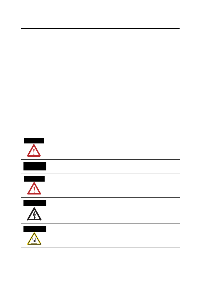
Throughout this manual, when necessary, we use notes to make you aware of safety considerations.
WARNING
Identifies information about practic es or circu mstances th at can cause an explosion in
a hazardous environment, which may lead to personal injury or death, property
damage, or economic loss.
IMPORTANT
ATTENTION
HOCK HAZARD
BURN HAZARD
Publication
Identifies information that is critical for successful application and understanding of
the product.
Identifies information about practices or circumstances that can lead to personal
injury or death, property damage, or economic loss. Attentions help you identify a
hazard, avoid a hazard and recognize the consequences.
Labels may be located on or insi de the equipm ent (e .g., dr ive or moto r) to ale rt p eople
that dangerous voltage may be present.
Labels may be located on or insi de the equipm ent (e .g., dr ive or moto r) to ale rt p eople
that surfaces may be dangerous temperatures.
1734-IN058B-EN-P - June 2005
Page 3

POINT I/O 24V dc Expansion Power Supply 3
N
Preventing Electrostatic Discharge
ATTENTIO
This equipment is sensitive to electrostatic discharge,
which can cause internal damage and affect normal
operation. Follow these guidelines when you handle this
equipment:
• Touch a grounded object to discharge potential static.
• Wear an approved grounding wriststrap.
• Do not touch connectors or pins on component
boards.
• Do not touch circuit components inside the
equipment.
• If available, use a static-safe workstation.
• When not in use, store the equipment in appropriate
static-safe packaging.
Publication
1734-IN058B-EN-P - June 2005
Page 4

4 POINT I/O 24V dc Expansion Power Supply
N
Environment and Enclosure
ATTENTIO
This equipment is intended for use in a Pollution Degree
2 industrial environment, in overvoltage Category II
applications (as defined in IEC publication 60664-1), at
altitudes up to 2000 meters without derating.
This equipment is considered Group 1, Class A industrial
equipment according to IEC/CISPR Publication 11.
Without appropriate precautions, there may be potential
difficulties ensuring electromagnetic compatibility in other
environments due to conducted as well as radiated
disturbance.
This equipment is supplied as “open type” equipment. It
must be mounted within an enclosure that is suitably
designed for those specific environmental conditions that
will be present and appropriately designed to prevent
personal injury resulting from accessibility to live parts.
The interior of the enclosure must be accessible only by
the use of a tool. Subsequent sections of this publication
may contain additional information regarding specific
enclosure type ratings that are required to comply with
certain product safety certifications.
See NEMA Standards publication 250 and IEC publication
60529, as applicable, for explanations of the degrees of
protection provided by different types of enclosure. Also,
see the appropriate sections in this publication, as well as
the Allen-Bradley publication 1770-4.1 (“Industrial
Automation Wiring and Grounding Guidelines”), for
additional installation requirements pertaining to this
equipment.
Publication
1734-IN058B-EN-P - June 2005
Page 5
POINT I/O 24V dc Expansion Power Supply 5
North American Hazardous Location Approval
The following information applies when
operating this equipment in hazardous
locations:
Products marked “CL I, DIV 2, GP A, B, C, D” are suitable
for use in Class I Division 2 Groups A, B, C, D, Hazardous
Locations and nonhazardous locations only. Each product
is supplied with markings on the rating nameplate
indicating the hazardous location temperature code. When
combining products within a system, the most adverse
temperature code (lowest “T” number) may be used to
help determine the overall temperature code of the
system. Combinations of equipment in your system are
subject to investigation by the local Authority Having
Jurisdiction at the time of installation.
EXPLOSION HAZARD -
WARNING
• Do not disconnect equipment unless
power has been removed or the area
is known to be nonhazardous.
• Do not disconnect connections to
this equipment unless power has
been removed or the area is known
to be nonhazardous. Secure any
external connections that mate to
this equipment by using screws,
sliding latches, threaded
connectors, or other means provided
with this product.
• Substitution of components may
impair suitability for Class I, Division
2.
• If this product contains batteries,
they must only be changed in an
area known to be nonhazardous.
Informations sur l’utilisation de cet équipement
en environnements dangereux:
Les produits marqués “CL I, DIV 2, GP A, B, C, D” ne
conviennent qu’à une utilisation en environnements de Classe I
Division 2 Groupes A, B, C, D dangereux et non dangereux.
Chaque produit est livré avec des marquages sur sa plaque
d’identification qui indiquent le code de température pour les
environnements dangereux. Lorsque plusieurs produits sont
combinés dans un système, le code de température le plus
défavorable (code de température le plus faible) peut être
utilisé pour déterminer le code de température global du
système. Les combinaisons d’équipements dans le système
sont sujettes à inspection par les autorités locales qualifiées
au moment de l’installation.
AVERTISSEMENT
RISQUE D’EXPLOSION –
• Couper le courant ou s’assurer que
l’environnement est classé non
dangereux avant de débrancher
l'équipement.
• Couper le courant ou s'assurer que
l’environnement est classé non
dangereux avant de débrancher les
connecteurs. Fixer tous les
connecteurs externes reliés à cet
équipement à l'aide de vis, loquets
coulissants, connecteurs filetés ou
autres moyens fournis avec ce
produit.
• La substitution de composants peut
rendre cet équipement inadapté à une
utilisation en environnement de
Classe 1, Division 2.
• S’assurer que l’environnement est
classé non dangereux avant de
changer les piles.
Publication
1734-IN058B-EN-P - June 2005
Page 6

6 POINT I/O 24V dc Expansion Power Supply
European Hazardous Location Approval
European Zone 2 Certification (The following applies when the product bears the
EEx marking.)
This equipment is intended for use in potentially explosive atmospheres as defined by
European Union Directive 94/9/EC.
DEMKO certifies that this equipment has been found to comply with the Essential Health
and Safety Requirements relating to the design and construction of Category 3 equipment
intended for use in potentially explosive atmospheres, given in Annex II to this Directive.
The examination and test results are recorded in confidential report No 03NK30347.
Compliance with the Essential Health and Safety Requirements has been assured by
compliance with EN 50021.
IMPORTANT
Publication
Observe the following additional Zone 2 certification
requirements.
• This equipment is not resistant to sunlight or
other sources of UV radiation.
• The secondary of a current transformer shall not
be open-circuited when applied in Class I, Zone
2 environments.
• Equipment of lesser Enclosure Type Rating must
be installed in an enclosure providing at least
IP54 protection when applied in Class I, Zone 2
environments.
• This equipment shall be used within its specified
ratings defined by Allen-Bradley.
• Provision shall be made to prevent the rated
voltage from being exceeded by transient
disturbances of more than 40% when applied in
Class I, Zone 2 environments.
1734-IN058B-EN-P - June 2005
Page 7

POINT I/O 24V dc Expansion Power Supply 7
N
N
N
ATTENTIO
ATTENTIO
ATTENTIO
Do not connect 120/240V ac to the 1734-EP24DC
terminals. Damage to the supply will result.
Use the 1734-EP24DC expansion power supply only with
1734 POINT I/O adapters, such as the 1734-ADN
DeviceNet adapter.
POINT I/O is grounded through the DIN rail to chassis
ground. Use zinc plated yellow-chromate steel DIN rail to
assure proper grounding. The use of other DIN rail
material (e.g., aluminum, plastic, etc.) that can corrode,
oxidize, or are poor conductors, can result in improper or
intermittent grounding.
Secure DIN rail to mounting surface approximately every
200 mm (7.8 inches).
Publication
1734-IN058B-EN-P - June 2005
Page 8

8 POINT I/O 24V dc Expansion Power Supply
About the Power Supply
The expansion power supply passes 24V dc field power to the I/O
modules to the right of it. The expansion power supply extends the
backplane bus power for up to 17 I/O modules to the right of the
supply and creates a new field voltage partition segment for driving
field devices. The expansion power supply separates field power
from I/O modules to the left of the unit, effectively providing
functional and logical partitioning for the following.
• Separate field power between input and output modules.
• Separate field power to the analog and digital modules.
• Group modules to perform a specific task or function.
The dark-gray color of the expansion power supply allows for easy
visual inspection and identification. Refer to the figure to identify
external power supply components.
Use multiple expansion power supplies with POINT I/O adapters to
assemble a full system. With any POINT I/O adapter, use an
expansion power supply to add additional modules in 4-17 module
increments, for a total of 63 I/O modules.
DIN Rail Locking
Screw (orange)
RTB Removal
Module
Label
Handle
Removable
Terminal
Block (RTB)
Publication
Interlocking Side
Pieces
43970
1734-IN058B-EN-P - June 2005
Page 9

POINT I/O 24V dc Expansion Power Supply 9
Install the Power Supply
To install the expansion power supply on the DIN rail, proceed as
follows.
WARNING
When you insert or remove the module while
backplane power is on, an electrical arc can occur .
This could cause an explosion in hazardous
location installations.
Be sure that power is removed or the area is
nonhazardous before proceeding. Repeated
electrical arcing causes excessive wear to contacts
on both the module and its mating connector . W orn
contacts may create electrical resistance that can
affect module operation.
1. Position the power supply vertically above the DIN rail.
2. Engage the interlocking side pieces with the unit on the left.
3. Press down firmly to install the power supply on the DIN rail.
The locking mechanism locks the module to the DIN rail.
Remove the Power Supply
To remove an expansion power supply, proceed as follows.
Publication
1734-IN058B-EN-P - June 2005
Page 10

10 POINT I/O 24V dc Expansion Power Supply
1. Pull up on the RTB removal handle to remove the terminal
block.
42511
2. Remove the module to the right of the 1734-EP24DC module
from its base unit.
3. Use a small-bladed screwdriver to rotate the DIN rail locking
screw to a vertical position.
This releases the locking mechanism.
4. Lift straight up to remove.
Replace the Power Supply
To install a replacement expansion power supply, proceed as foll ows.
WARNING
Publication
When you connect or disconnect the removable
terminal block (RTB) with field-side power applied,
an electrical arc can occur. This could cause an
explosion in hazardous location installations.
Be sure that power is removed or the area is
nonhazardous before proceeding.
1734-IN058B-EN-P - June 2005
Page 11

POINT I/O 24V dc Expansion Power Supply 11
N
N
1. Remove the module to the right of the power supply from its
base unit.
2. Position the power supply vertically above the DIN rail.
3. Slide the power supply down allowing the interlocking side
pieces to engage the adjacent modules (both left and right
sides).
4. Press firmly to seat the power supply on the DIN rail.
The power supply locking mechanism snaps into place.
5. Reinsert the module into the base next to the expansion
power supply.
Wire the Power Supply
WARNING
ATTENTIO
ATTENTIO
If you connect or disconnect wiring while the field-side
power is on, an electrical arc can occur. This could cause
an explosion in hazardous location installations. Be sure
that power is removed or the area is nonhazardous before
proceeding.
Use the 1734-EP24DC expansion power supply only with
adapter class products.
Use the 1734-EP24DC expansion power supply only with
1734 POINT I/O adapters, such as the 1734-ADN
DeviceNet adapter.
Publication
1734-IN058B-EN-P - June 2005
Page 12

12 POINT I/O 24V dc Expansion Power Supply
NC = No Connection
CHAS GND = Chassis Ground
C = Common
V = Supply
12/24Vdc Wiring
12/24V dc
Do not connect
120/240V ac power to
this supply.
V = 12/24V dc C = Common
CHAS GND = Chassis Ground
Publication
1734-IN058B-EN-P - June 2005
V dc
NC
C
V
01
NC NC
CHAS
GND
C
3
5
7
2
CHAS
GND
4
C
6
VV
NC
CHAS GNDCHAS GND
C
V
This supply will be
connected to the
internal field power
bus.
41970
EP24
Page 13

POINT I/O 24V dc Expansion Power Supply 13
Connect Terminal Terminals (for continuing power)
+V dc 6 7
-V dc 4 5
Chas Gnd 2 3
12/24V dc becomes the internal field power bus for modules to the right.
Example of Continuing Power
ADN
Adapter
Status
DeviceNet
Status
PointBus
Status
1734-ADN
System
Power
DeviceNet
Power
12/24V dc only
EP24DC
O
I
1734-EP24DC
System
Power
r
DeviceNet
Power
I
E
E
E
2
2
2
C
C
C
0 1
0 1
0 1
0 1
1
O
I
I
O
B
B
B
B
2
2
4
4
E
E
0 1
0 1
0 1
0 1
Example of Continued Power
1734adn4
Publication
1734-IN058B-EN-P - June 2005
Page 14

14 POINT I/O 24V dc Expansion Power Supply
Example of Functional Partitioning
ADN
Adapter
Status
DeviceNet
Status
PointBus
Status
1734-ADN
System
Power
DeviceNet
Power
12/24V dc
Digital Supply
EP24DC
O
I
1734-EP24DC
System
Power
r
DeviceNet
Power
I
E
E
E
2
2
2
C
C
C
0 1
0 1
0 1
0 1
1
O
I
I
O
B
B
B
B
2
2
4
4
E
E
0 1
0 1
0 1
0 1
12/24V dc
Analog
Supply
1734adn4
Publication
1734-IN058B-EN-P - June 2005
Page 15

POINT I/O 24V dc Expansion Power Supply 15
Example of Logical Partitioning
ADN
Adapter
Status
DeviceNet
Status
PointBus
Status
1734-ADN
Status
Power
DeviceNet
Power
24V dc Supply
EP24DC
I
O
I
I
O
O
B
E
E
B
2
2
2
C
0 1
2
C
E
1734-EP24DC
System
Power
r
DeviceNet
Power
0 1
0 1
0 1
0 1
O
B
B
B
2
2
4
E
E
0 1
0 1
0 1
1
12V dc
Supply
1734adn4
Publication
1734-IN058B-EN-P - June 2005
Page 16

16 POINT I/O 24V dc Expansion Power Supply
Specifications
1734-EP24DC POINT I/O 24V dc Expansion Power Supply
Specification Value
I/O Module Capacity 4-17 modules, depending on current rating of each module
Input Voltage Rating 24V dc nominal
10…28.8V dc range
Field Side Power
Requirements
Inrush Current 6 A maximum for 10 ms
Indicators 1 Green Field Power Status Indicator
POINTBus Output Current Horizontal mounting -
Input Overvoltage Protection Reverse polarity protected
Interruption Output voltage will stay within specifications when input
Module Location Between I/O modules in 1734 system
Limitations Use with POINT I/O Adapters only
Dimensions millimeters
inches
Weight 0.12 kg (0.27 lb)
Terminal Base Screw Torque 0.6 Nm (7 lb-in)
24V dc (+20% = 28.8V dc maximum) @ 400 mA maximum
1 Green 5V System Power Indicator
1 A at 10…19.2V input;
1.3 A at 19.2…28.8V input
Vertical mounting 1 A at 10…28.8V input
drops out for 10ms at 10V with maximum load.
Breaks field power bus
76.2H x 25.4W x 133.4L mm
(3.00H x 1.00W x 5.25L in)
Publication
1734-IN058B-EN-P - June 2005
Page 17

POINT I/O 24V dc Expansion Power Supply 17
General Specifications
Specification Value
Power Consumption 9.8 W maximum @ 28.8V dc
Power Dissipation 3.0 W maximum @ 28.8V dc
Thermal Dissipation 10.0 BTU/hr maximum @ 28.8V dc
Isolation Voltage
(continuous-voltage
withstand rating)
Field Power Bus
Supply Voltage
Voltage Range
Supply Current
50V continuous
Tested to withstand 2600V dc for 60 s
24V dc nominal
10…28.8V dc range
10 A maximum
Environmental Specifications
Specification Value
Operational Temperature IEC 60068-2-1 (Test Ad, Operating Cold),
IEC 60068-2-2 (Test Bd, Operating Dry Heat),
IEC 60068-2-14 (Test Nb, Operating Thermal Shock)
-20...55 °C (-4...131 °F)
Storage Temperature IEC60068-2-1 (Test Ab, Unpackaged Non-operating Cold)
IEC60068-2-2 (Test Bb, Unpackaged Non-operating Dry
Heat)
IEC60068-2-14 (Test Na, Unpackaged Non-operating
Thermal Shock)
-40...85
°C (-40...185 °F)
Relative Humidity IEC60068-2-30
(Test Db, Unpackaged Non-operating Damp Heat)
5...95% non-condensing
Shock Operating IEC60068-2-27 (Test Ea, Unpackaged Shock) 30 g
Shock Non-operating IEC60068-2-27 (Test Ea, Unpackaged Shock) 50 g
Vibration IEC 60068-2-6 (Test Fc, Operating)
5 g @ 10-500 Hz
Publication
1734-IN058B-EN-P - June 2005
Page 18

18 POINT I/O 24V dc Expansion Power Supply
Environmental Specifications
Emissions CISPR 11: Group 1, Class A
ESD Immunity IEC6100-4-2
6 kV contact discharges
8 kV air discharges
Radiated RF Immunity IEC 61000-4-3
EFT/B Immunity IEC 61000-4-4
Surge Transient Immunity IEC 61000-4-5
Conducted RF Immunity IEC61000-4-6
Enclosure Type Rating None (open-style)
Conductor Size #22…#14 AWG (0.324…2.08 sq. mm)
Conductor Category
1
10V/m with 1 KHz sine-wave 80% AM
from 30 MHz to 2000 MHz
10V/m with 200 Hz 50% Pulse 100% AM at 900 MHz
10V/m with 200 Hz 50% Pulse 100% AM at 1890 MHz
+
4 kV at 2.5 kHz on power ports
+
1 kV line-line (DM) and + 2kV line-earth (CM)
on power ports
10Vrms with 1 kHz sine-wave 80% AM
from 150 kHz to 80 MHz
solid or stranded copper wire rated @ 75 °C or greater
3/64 inch (1.2 mm) insulation maximum
1 - on power ports
1 Use this Conductor Category information for planning conductor routing. Refer to publication
1770-4.1, Industrial Automation Wiring and Grounding Guidelines.
Publication
1734-IN058B-EN-P - June 2005
Page 19

Environmental Specifications
Current Derating for Mounting
1.3
1.0
Current
0.5
10 19.2 28.8
Horizontal - 1A @ (10-19.2V); 1.3A @ (19.2-28.8)
Vertical - 1A @ (10-28.8V)
POINT I/O 24V dc Expansion Power Supply 19
Voltage
43971
Publication
1734-IN058B-EN-P - June 2005
Page 20

Certifications
Certifications
1
(when product is marked)
c-UL-us UL Listed Industrial Control Equipment,
certified for U.S. and Canada
c-UL-us UL Listed for Class I, Division 2, Group A,B,C,D
Hazardous Locations, certified for U.S. and Canada
CE European Union 89/336/EEC EMC Directive,
compliant with:
EN 50082-2; Industrial Immunity
EN 61326; Meas./Control/Lab., Industrial
Requirements
EN 61000-6-2; Industrial Immunity
EN 61000-6-4; Industrial Emissions
C-Tick Australian Radiocommunications Act,
compliant with:
AS/NZS CISPR11; Industrial Emissions
EE
X European Union 94/9/EC ATEX Directive,
compliant with:
EN 50021; Potentially Explosive Atmospheres,
Protection “n” (Zone 2)
1 See the Product Certification link at www.ab.com for Declarations of Conformity, Certificates,
and other certification details.
POINT I/O and POINTBus are trademarks of Rockwell Automation.
Publication 1734-IN058B-EN-P - June 2005 PN 957955-68
Supersedes Publication 1734-IN058A-EN-P - August 2000 Copyright © 2005 Rockwell Automation, Inc. All rights reserved. Printed in the U.S.A.
ö
 Loading...