

Page 1
Installation Instructions
POINT I/O Common Terminal Module and
Voltage Terminal Module
Catalog No. 1734-CTM, Series C, and 1734-VTM, Series C
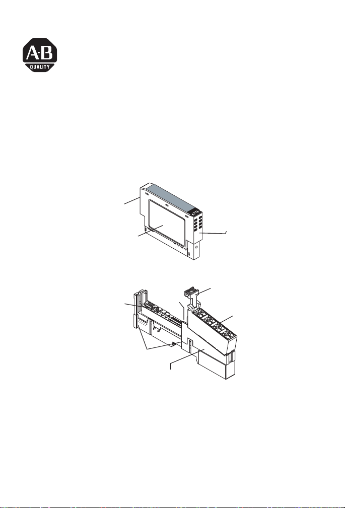
Module Locking Mechanism
Insertable I/O Module
Module Wiring Diagram
DIN Rail
Mechanical keying
(orange)
Interlocking
Side Pieces
Locking
Screw
(orange)
Mounting Base
RTB Removable Handle
Removable Terminal
Block (RTB)
31538-M
The Wiring Base Assembly consists of Mounting Base, 1734-MB,
and Removable Terminal Block, 1734-RTB or 1734-RTBS.
Publication 1734-IN024A-EN-E - March 2005
Page 2
2 POINT I/O Common Terminal Module and Voltage Terminal Module
S
Important User Information
Solid state equipment has operational characteristics differing from those of
electromechanical equipment. Safety Guidelines for the Application, Installation and
Maintenance of Solid State Controls (Publication SGI-1.1 available from your local Rockwell
Automation sales office or online at http://literature.rockwellautomation.com) describes
some important differences between solid state equipment and hard-wired
electromechanical devices. Because of this difference, and also because of the wide variety
of uses for solid state equipment, all persons responsible for applying this equipment must
satisfy themselves that each intended application of this equipment is acceptable.
In no event will Rockwell Automation, Inc. be responsible or liable for indirect or
consequential damages resulting from the use or application of this equipment.
The examples and diagrams in this manual are included solely for illustrative purposes.
Because of the many variables and requirements associated with any particular installation,
Rockwell Automation, Inc. cannot assume responsibility or liability for actual use based on
the examples and diagrams.
No patent liability is assumed by Rockwell Automation, Inc. with respect to use of
information, circuits, equipment, or software described in this manual.
Reproduction of the contents of this manual, in whole or in part, without written permission
of Rockwell Automation, Inc., is prohibited.
Throughout this manual, when necessary, we use notes to make you aware of safety
considerations.
WARNING
Identifies information about practices or circumstances that can cause an explosion in a
hazardous environment, which may lead to pers onal injury or death, property damage, or
economic loss.
IMPORTANT
ATTENTION
HOCK HAZARD
BURN HAZARD
Publication
Identifies information that is critical for successful application and understanding of the
product.
Identifies information about practices or ci rcumstances that can lead to pe rsonal injury or
death, property damage, or economic loss. Attentions help you:
• identify a hazard
• avoid a hazard
• recognize the consequence
Labels may be located on or inside the equipment (e.g., drive or motor) to alert people
that dangerous voltage may be present.
Labels may be located on or inside the equipment (e.g., drive or motor) to alert people
that surfaces may be dangerous temperatures.
1734-IN024A-EN-E - March 2005
Page 3

POINT I/O Common Terminal Module and Voltage Terminal Module 3
WARNING
Environment and Enclosure
This equipment is intended for use in a Pollution Degree
2 industrial environment, in overvoltage Category II
applications (as defined in IEC publication 60664-1), at
altitudes up to 2000 meters without derating.
This equipment is considered Group 1, Class A industrial
equipment according to IEC/CISPR Publication 11.
Without appropriate precautions, there may be potential
difficulties ensuring electromagnetic compatibility in
other environments due to conducted as well as radiated
disturbance.
This equipment is supplied as “open type” equipment. It
must be mounted within an enclosure that is suitably
designed for those specific environmental conditions that
will be present and appropriately designed to prevent
personal injury resulting from accessibility to live parts.
The interior of the enclosure must be accessible only by
the use of a tool. Subsequent sections of this publication
may contain additional information regarding specific
enclosure type ratings that are required to comply with
certain product safety certifications.
See NEMA Standards publication 250 and IEC publication
60529, as applicable, for explanations of the degrees of
protection provided by different types of enclosure. Also,
see the appropriate sections in this publication, as well as
the Allen-Bradley publication 1770-4.1 (“Industrial
Automation Wiring and Grounding Guidelines”), for
additional installation requirements pertaining to this
equipment.
Publication
1734-IN024A-EN-E - March 2005
Page 4

4 POINT I/O Common Terminal Module and Voltage Terminal Module
WARNING
Explosion Hazard
Do not disconnect equipment unless power has been
removed or the area is known to be nonhazardous.
Do not disconnect connections to this equipment unless
power has been removed or the area is known to be
nonhazardous. Secure any external connections that mate
to this equipment by using screws, sliding latches,
threaded connectors, or other means provided with this
product.
Substitution of components may impair suitability for
Class I, Division 2.
If this product contains batteries, they must only be
changed in an area known to be nonhazardous.
About the Modules
The POINT I/O Common Terminal Module and Voltage Terminal
Module provide expansion of the termination capability of POINT
I/O. The modules support higher density (8 channel) POINT I/O
modules and management of wiring of field devices to the POINT
I/O solution.
Publication
1734-IN024A-EN-E - March 2005
Page 5
POINT I/O Common Terminal Module and Voltage Terminal Module 5
Install the Mounting Base
To install the mounting base on the DIN rail, proceed as follows.
1. Position the mounting base vertically above the installed units
(adapter, power supply, or existing module).
2. Slide the mounting base down so that the interlocking side
pieces to engage the adjacent module or adapter.
3. Press firmly to seat the mounting base on the DIN rail. The
mounting base snaps into place.
Install the Module
Install the module before or after mounting base installation. Be sure
to correctly key the mounting base before installing the module into
the mounting base. In addition, be sure to position the mounting
base locking screw horizontal referenced to the base.
WARNING
When you insert or remove the module while backplane
power is on, an electrical arc can occur. This could cause
an explosion in hazardous location installations.
Be sure that power is removed or the area is
nonhazardous before proceeding. Repeated electrical
arcing causes excessive wear to contacts on both the
module and its mating connector. Worn contacts may
create electrical resistance that can affect module
operation.
1. Using a bladed screwdriver, rotate the keyswitch on the
mounting base clockwise until the number required for the
type of module you are installing aligns with the notch in the
base.
Publication
1734-IN024A-EN-E - March 2005
Page 6

6 POINT I/O Common Terminal Module and Voltage Terminal Module
2. Make certain the DIN rail locking screw is in the horizontal
position.
You cannot insert the module if the locking mechanism is
unlocked.
3. Insert the module straight down into the mounting base and
press to secure.
The module locks into place.
Install the Removable Terminal Block (RTB)
You will find the RTB supplied with the wiring base assembly. To
remove, pull up on the RTB handle. You can now remove the
mounting base and replace as necessary without removing any of the
wiring. To reinsert the RTB, proceed as follows.
1. Insert the end opposite the handle into the base unit.
This end has a curved section that engages with the wiring
base.
2. Rotate the terminal block into the wiring base until it locks
itself in place.
3. If an I/O module is installed, snap the RTB handle into place
on the module.
Publication
1734-IN024A-EN-E - March 2005
Page 7

POINT I/O Common Terminal Module and Voltage Terminal Module 7
Remove a Mounting Base
To remove a mounting base, y ou must remove any installed module,
and the module installed in the base to the right. Remove the
removable terminal block (if wired).
1. Unlatch the RTB handle on the I/O module.
2. Pull on the RTB handle to remove the removable terminal
block.
3. Press on the module lock on the top of the module.
4. Pull on the I/O module to remove from the base.
WARNING
When you insert or remove the module while backplane
power is on, an electrical arc can occur. This could cause
an explosion in hazardous location installations.
Be sure that power is removed or the area is
nonhazardous before proceeding. Repeated electrical
arcing causes excessive wear to contacts on both the
module and its mating connector. Worn contacts may
create electrical resistance that can affect module
operation.
5. Repeat steps 1, 2, 3, and 4 for the module to the right.
6. Use a small-bladed screwdriver to rotate the orange base
locking screw to a vertical position.
This releases the locking mechanism.
7. Lift straight up to remove.
Publication
1734-IN024A-EN-E - March 2005
Page 8

8 POINT I/O Common Terminal Module and Voltage Terminal Module
Wire the Modules
1734-VTM
0
1
1734
VTM
Voltage Out
Voltage Out
Voltage Out
Voltage Out
Voltage Out = 0 to 7
Voltage Out
Voltage Out
Voltage Out
Voltage Out
1734-CTM
Common
Common
Common
Common
Common = 0 to 7
0
1
1734
CTM
Common
Common
Common
Common
43929
Publication
1734-IN024A-EN-E - March 2005
Page 9

POINT I/O Common Terminal Module and Voltage Terminal Module 9
Sink Input Wiring
1734-IB8
0
In 0
2
In 2
4
In 4
6
In 6
In 1
In 3
In 5
In 7
1
Prox
3
5
3-wire
7
Prox
2-wire
1734-VTM
0
V
2
V
V
4
V
V
6
V
V
V
1
3
5
7
2
4
6
V = Voltage Out
1
0
C
C
3
C
C
5
C
C
7
C
C
C = Common
43927
1734-CTM
Publication
1734-IN024A-EN-E - March 2005
Page 10

10 POINT I/O Common Terminal Module and Voltage Terminal Module
t
Source Input Wiring
1734-IV8
1
0
In 1
In 0
In 2
In 6
3
In 3
5
In 5
7
In 7
2
4
In 4
6
2-wire
Prox
3-wire
Prox
1734-VTM
0
C
2
C
4
C
6
C
C = Common
C
C
C
C
1734-CTM
1
1
3
5
7
0
V
V
3
2
V
V
5
4
V
V
6
V
7
V
V = Voltage Ou
43927
Publication
1734-IN024A-EN-E - March 2005
Page 11

POINT I/O Common Terminal Module and Voltage Terminal Module 11
Source Output Wiring
1734-OB8
0
Out 0
2
Out 2
4
Out 4
6
Out 6
Sink Output Wiring
1734-OV8
0
Out 0
Out 1
2
Out 2
4
Out 4
6
Out 6
Out 3
Out 5
Out 7
Out 1
Out 3
Out 5
Out 7
1
3
5
7
1734-CTM
1
3
5
7
Load
Load
Load
Load
0
CC
2
C
4
C
6
C
C = Common
1
3
C
5
C
7
C
43928
1734-VTM
Load
Load
Load
Load
0
VV
2
V
4
V
6
V
1
3
V
5
V
7
V
Publication
V = Voltage Out
1734-IN024A-EN-E - March 2005
43928
Page 12

12 POINT I/O Common Terminal Module and Voltage Terminal Module
t
General Purpose Wiring
1734
Adapter
VTM
1734
CTM
V = Voltage Ou
C = Common
Other
Devices
Power
Supply
43926
Publication
1734-IN024A-EN-E - March 2005
Page 13

POINT I/O Common Terminal Module and Voltage Terminal Module 13
4V dc 2 Input Sink Module Cat. No. 1734-IB2
Safety Approvals
North American Hazardous Location Approval
The 1734-CTM and 1734-VTM modules, Series C, are North American
Hazardous Location approved.
The following information applies when
operating this equipment in hazardous
locations:
Products marked “CL I, DIV 2, GP A, B, C, D” are suitable
for use in Class I Division 2 Groups A, B, C, D, Hazardous
Locations and nonhazardous locations only. Each product
is supplied with markings on the rating nameplate
indicating the hazardous location temperature code. When
combining products within a system, the most adverse
temperature code (lowest “T” number) may be used to
help determine the overall temperature code of the
system. Combinations of equipment in your system are
subject to investigation by the local Authority Having
Jurisdiction at the time of installation.
EXPLOSION HAZARD -
WARNING
• Do not disconnect equipment unless
power has been removed or the area
is known to be nonhazardous.
• Do not disconnect connections to
this equipment unless power has
been removed or the area is known
to be nonhazardous. Secure any
external connections that mate to
this equipment by using screws,
sliding latches, threaded
connectors, or other means provided
with this product.
• Substitution of components may
impair suitability for Class I, Division
2.
• If this product contains batteries,
they must only be changed in an
area known to be nonhazardous.
Informations sur l’utilisation de cet équipement
en environnements dangereux:
Les produits marqués “CL I, DIV 2, GP A, B, C, D” ne
conviennent qu’à une utilisation en environnements de Classe I
Division 2 Groupes A, B, C, D dangereux et non dangereux.
Chaque produit est livré avec des marquages sur sa plaque
d’identification qui indiquent le code de température pour les
environnements dangereux. Lorsque plusieurs produits sont
combinés dans un système, le code de température le plus
défavorable (code de température le plus faible) peut être
utilisé pour déterminer le code de température global du
système. Les combinaisons d’équipements dans le système
sont sujettes à inspection par les autorités locales qualifiées
au moment de l’installation.
RISQUE D’EXPLOSION –
AVERTISSEMENT
• Couper le courant ou s’assurer que
l’environnement est classé non
dangereux avant de débrancher
l'équipement.
• Couper le courant ou s'assurer que
l’environnement est classé non
dangereux avant de débrancher les
connecteurs. Fixer tous les
connecteurs externes reliés à cet
équipement à l'aide de vis, loquets
coulissants, connecteurs filetés ou
autres moyens fournis avec ce
produit.
• La substitution de composants peut
rendre cet équipement inadapté à une
utilisation en environnement de
Classe 1, Division 2.
• S’assurer que l’environnement est
classé non dangereux avant de
changer les piles.
Publication
1734-IN024A-EN-E - March 2005
Page 14

14 POINT I/O Common Terminal Module and Voltage Terminal Module
Specifications
Indicators None
Keyswitch Position 5
Module Location 1734-TB or -TBS wiring base assembly
Pointbus Current None
Power Dissipation None
Thermal Dissipation None
Isolation Voltage (Continuous
Voltage Withstand Rating)
Field Power Bus
Supply Voltage
Output Current
Dimensions Inches
(Millimeters)
Environmental Conditions
Operational Temperature IEC 60068-2-1 (Test Ad, Operating Cold),
Storage Temperature IEC 60068-2-1 (Test Ab, Unpackaged Nonoperating Cold),
Relative Humidity IEC 60068-2-30 (Test Db, Unpackaged Nonoperating
Shock
Operating
Non-operating
Vibration IEC 60068-2-6, (Test Fc, Operating) Tested 5g @ 10-500Hz
Enclosure Type Rating None (open-style)
Conductors Wire Size
Tested to 1600 Vrms for 60 seconds
10-28.8V dc, 120/240V ac
2A per point, 4A module max.
2.2H x 0.47W x 2.97L
(56H x 12W x 75.5L)
IEC 60068-2-2 (Test Bd, Operating Dry Heat),
IEC 60068-2-14 (Test Nb, Operating Thermal Shock):
-20 to 55°C (-4 to 131°F)
IEC 60068-2-2 (Test Bb, Unpackaged Nonoperating Dry Heat),
IEC 60068-2-14 (Test Na, Unpackaged Nonoperating Thermal
Shock): -40 to 85°C (-40 to 185°F)
Damp Heat):
5 to 95% noncondensing
IEC 60068-2-27 (Test Ea, Unpackaged Shock)
30g peak acceleration
50g peak acceleration
2
14 AWG (2.5mm
copper wire rated at 75°C or greater
3/64 inch (1.2mm) insulation maximum
) - 22 AWG (0.25mm2) solid or stranded
Publication
1734-IN024A-EN-E - March 2005
Page 15

POINT I/O Common Terminal Module and Voltage Terminal Module 15
Terminal Base Screw Torque 7 pound-inches (0.8Nm)
Mass 1.09 oz/30.9 grams
Field Wiring Terminations 1734-VTM, Series C
0 - Voltage Out1 - Voltage Out
2 - Voltage Out3 - Voltage Out
4 - Voltage Out5 - Voltage Out
6 - Voltage Out7 - Voltage Out
1734-CTM, Series C
0 - Common1 - Common
2 - Common3 - Common
4 - Common5 - Common
6 - Common7 - Common
Certifications (when product is
marked)
1 See the Product Certification link at www.ab.com for Declaration of Conformity, Certificates, and
other certification details.
POINT I/O and POINTBus are trademarks of Rockwell Automation.
1
C-UL-US
- UL Listed for Class I, Division 2, Groups A,
B, C, and D Hazardous locations, certified
for US and Canada
Publication
1734-IN024A-EN-E - March 2005
Page 16

Rockwell Automation Support
Rockwell Automation provides technical info rmation on the web to assist you
in using its products. At http://support .rockwell aut omation .com, y ou can find
technical manuals, a knowledge base of FAQs, technical and application
notes, sample code and links to software service packs, and a MySupport
feature that you can customize to make the best use of these tools.
For an additional level of technical phone support for installation,
configuration and troubleshooting, we offer TechConnect Support programs.
For more information, contact your local distributor or Rockwell Automation
representative, or visit http://support.rockwellautomation.com.
Installation Assistance
If you experience a problem with a hardware module wit hin the first 24 hours
of installation, please review the information that's contained in this manual.
You can also contact a special Customer Support number for initial help in
getting your module up and running:
United States 1.440.646.3223 Monday – Friday, 8am – 5pm EST
Outside United States Please contact your local Rockwell Automation representative for any
New Product Satisfaction Return
Rockwell tests all of its products to ensure that they are ful ly operational when
shipped from the manufacturing facility. However, if your product is not
functioning and needs to be returned:
United States Contact your distributor. You must provide a Customer Support case number
Outside United States Please contact your local Rockwell Automation representative for return
technical support issues.
(see phone number above to obtain one) to your distributor in order to
complete the return process.
procedure.
Publication 1734-IN024A-EN-E - March 2005 PN 957955-20
Copyright © 2005 Rockwell Automation, Inc. All rights reserved. Printed in the U.S.A.
 Loading...