

Page 1
Installation Instructions
POINT I/O
Use this document to install and wire the following components of your POINT™ I/O system:
Interface: 1734-ADN, -PDN Bases: 1734-TB, -TBS, -TB3, -TB3S
POINT I/O modules have no switches to set. You set module parameters with a software configuration tool. To obtain EDS files for use in
configuration, go to: http://www.ab.com/networks/eds
(RTB usage covered)
This product installation information is also available at: http://www.ab.com/manuals/io/
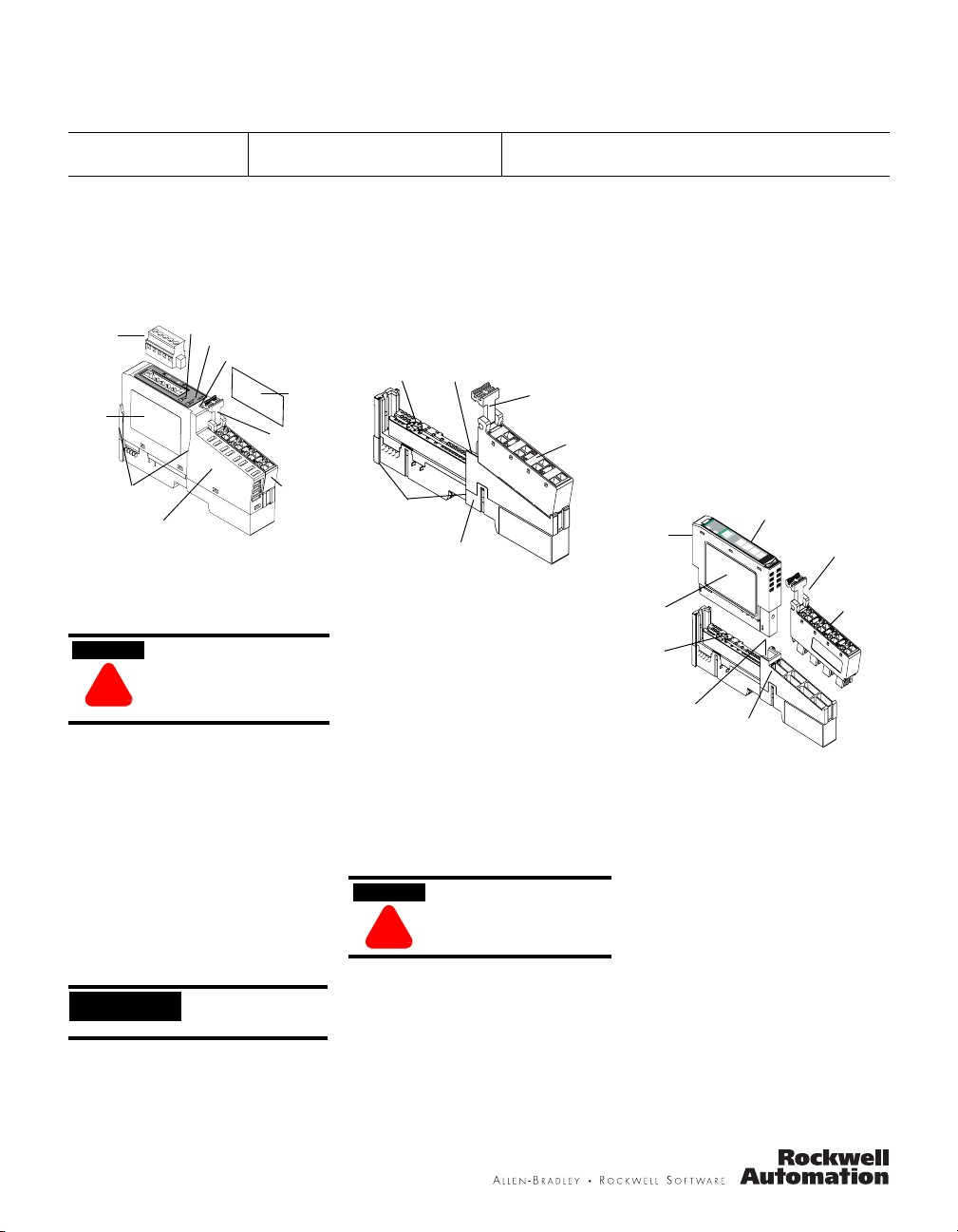
Installing the POINT I/O Adapter or Communication Interface
The 1734-ADN DeviceNet adapter and
1734-PDN communication interface install
onto a DeviceNet network.
DeviceNet
connector
Module
label
Interlocking
side pieces
1. Position the interface above the DIN rail.
2. Press down firmly to install the interface
3. The locking mechanism will lock the
4. Remove safety end cap. Slide it up to
1734-PDN Adaptor
on the DIN rail.
interface to the DIN rail.
expose backplane and power connections.
ATTENTION
!
If installing a replacement interface to an
existing system:
1. Position the interface above the DIN rail.
2. Slide the interface down allowing the
interlocking side pieces to engage the
adjacent module.
3. Press firmly to seat the interface on the
DIN rail. The interface locking mechanism
will snap into place.
4. To remove the interface from the DIN rail,
pull up on the RTB removal handle to
remove the terminal block.
5. Use a small bladed screwdriver to rotate
the DIN rail locking screw to a vertical
position.
6. This releases the locking mechanism.
Then lift straight up to remove.
System Power Indicator
Module Power Indicator
DIN Rail Locking Screw
Do not discard end cap. Use
end cap to cover exposed
connections on the last terminal
base in the chassis. Failure to
do so could result in injury or
equipment damage.
(orange)
Safety
End Cap
RTB Removal
Handle
Removable
Ter mi na l
Block
Installing the Field Potential Dist.
IMPORTANT
The 1734-FPD installs onto a DeviceNet
network using the same steps as the
1734-PDN communication interface with one
additional step included.
The 1734-FPD looks
like the 1734-PDN but
has no indicators.
After positioning the 1734-FPD above the
DIN rail, engage the interlocking side pieces
with the unit on the left.
Installing the POINT I/O Wiring Base
The wiring base consists of a base and a
removable terminal block (RTB). The
1734-TB uses screw-clamp terminations; the
1734-TBS uses spring-clamp terminations.
Mech. Keying
Interlocking
Side Pieces
Installing the Wiring Base
1. Position wiring base vertically above
installed units (interface, power supply or
existing module.
2. Slide the wiring base down allowing the
interlocking side pieces to engage the
adjacent module or interface.
3. Press firmly to seat the wiring base on the
DIN rail. The wiring base will snap into
place.
4. To remove the wiring base from the DIN
rail, remove the module, and use a small
bladed screwdriver to rotate the base
locking screw to a vertical position. This
releases the locking mechanism. Then lift
straight up to remove.
Installing the Removable Terminal Block
A removable terminal block is supplied with
your terminal base. To remove, pull up on
the RTB removal handle.
ATTENTION
!
This allows the base to be removed and
replaced as necessary without removing any
of the wiring. To reinsert the removable
terminal block:
1. Insert the end opposite the handle into the
base unit. This end has a curved section
that engages the wiring base.
2. Rotate the terminal block into the wiring
base until it locks itself in place.
DIN Rail Locking Screw (orange)
Wiring Base
Do not pull on the installed
wiring to remove a terminal
block. A shock hazard exists if
power is applied to the
terminal block.
Modules:1734-IA2, IB2, -IB4, -IJ, -IK, -IM2, -IV2, -IV4, -IE2C, -OA2,
-OE2C, -OW2, -OB2E, -OB4E, -VHSC24, -VHSC5
3. If an I/O module is installed, snap the RTB
handle into place on the module.
4. Insert module straight down into wiring
base and press to secure. Module locks
into place.
Removing a Wiring Base
To remove a wiring base, you must remove
any installed module, and remove the
removable terminal block (if wired). Then
follow these steps:
RTB
6
Removal
Handle
RTB
1. Remove the RTB (if wired).
2. Turn the wiring base locking screw to a
vertical position to unlock the base from
the DIN rail.
3. Slide base up to release it from its mating
units.
Installing the I/O Module
I/O Module
le
u
s
d
o
tu
M
ta
S
Network
Status
Module
Locking
Mechanism
Module
Wiring
Diagram
Mech.
Keying
DIN Rail
Locking Screw
(orange)
The module can be installed before, or after
base installation. Make sure that the wiring
base is correctly keyed before installing the
module into the wiring base. In addition,
make sure the wiring base locking screw is
positioned horizontal according to the base.
1. Using a bladed screwdriver, rotate the
keyswitch on the wiring base clockwise to
until the number required for the type of
module being installed aligns with the
notch in the base.
2. Make certain the DIN rail locking screw is
in the horizontal position. (You cannot
insert the module if the locking
mechanism is unlocked.)
3. Insert the module straight down into the
wiring base and press to secure. The
module will lock into place.
NODE:
24VDC
Source
Output
0
1
Wiring Base
2
3
1734
B4E
O
RTB
Removal
Handle
RTB
30880-MB
Page 2
2 POINT I/O
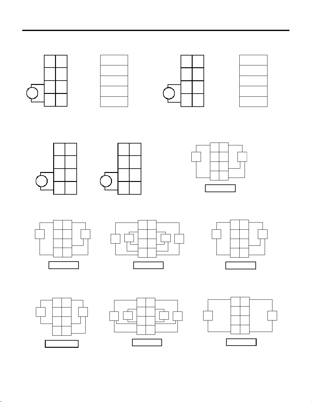
Wiring Diagrams
1734-ADN
0
V dc
12/24V dc
Power
2
1
4
6
12/24V dc
Power
NC = No Connection Chass GND = Chassis Ground
C = Common V = Supply
1
Do not connect 120/240V ac power to this supply. This dc
supply will be connected to the internal pow er bus.
V dc
V = 12/24V dc, C = Common Chass GND = Chassis Ground
This supply will be connected to the internal power b us.
Prox
V = 12/24V dc, C = Common
Field power is supplied from power bus
NC
Chass
Gnd
C
V
1734-IB2
1
NC
3
Chass
Gnd
5
C
7
V
0
NC
2
Chass
Gnd
4
C
6
V
0
In 0 In 1
2
NC
NC
4
C
C
6
VV
IB2 Sink Input
30880
NC
Chass
Gnd
C
V
1
3
5
7
DeviceNet
connection
1734-FPD
1
3
5
Daisy
chain
power
7
out to
modules
Prox
41966
Black
Blue
Bare
White
Red
0
NC
2
120/240V ac
Power
Chass
Gnd
4
L2/
V ac
N
6
L1
L2/N = Neutral, L1 = 120/240V ac
This supply will be connected to
the internal power bus.
Prox
V = 12/24V dc, C = Common
Field power is supplied from power bus
-V
CAN - Low
Shield
CAN - High
+V
1
NC
3
Chass
Gnd
5
L2/
N
7
L1
1734-IB4
0
In 0 In 1
2
In 2
4
6
IB4 Sink Input
Daisy
chain
power
out to
modules
1
3
In 3
5
C
C
7
VV
1734-PDN
0
1
NC
NC
2
3
Chass
V dc
Chass
Gnd
4
C
6
V
Gnd
C
V
5
Daisy chain
7
power out to
modules
DeviceNet
connection
12/24V dc
Power
NC = No Connection Chass GND = Chassis Ground
C = Common V = Supply
1734-IA2
0
1
Ch 0 Ch 1
2
Prox
2-Wire 3-Wire
Ch 0 = Channel 0 Ch 1 = Channel 1 NC = No Connection
L2/N = 120V ac Neutral L1 = 120V ac
Prox
ProxProx
41967
Ch 0 = Channel 0 Ch 1 = Channel 1 NC = No Connection
L2/N = 220V ac Neutral L1 = 220V ac
3
NC
NC
4
5
L2/N
L2/N
6
7
L1 L1
IA2 Input
Prox
2-Wire 3-Wire
Prox
1734-IM2
0
Ch 0 Ch 1
2
NC
NC
4
L2/N
L2/N
6
L1 L1
IM2 Input
Black
Blue
Bare
White
Red
41960
1
3
5
7
-V
CAN - Low
Shield
CAN - High
+V
Prox
41968
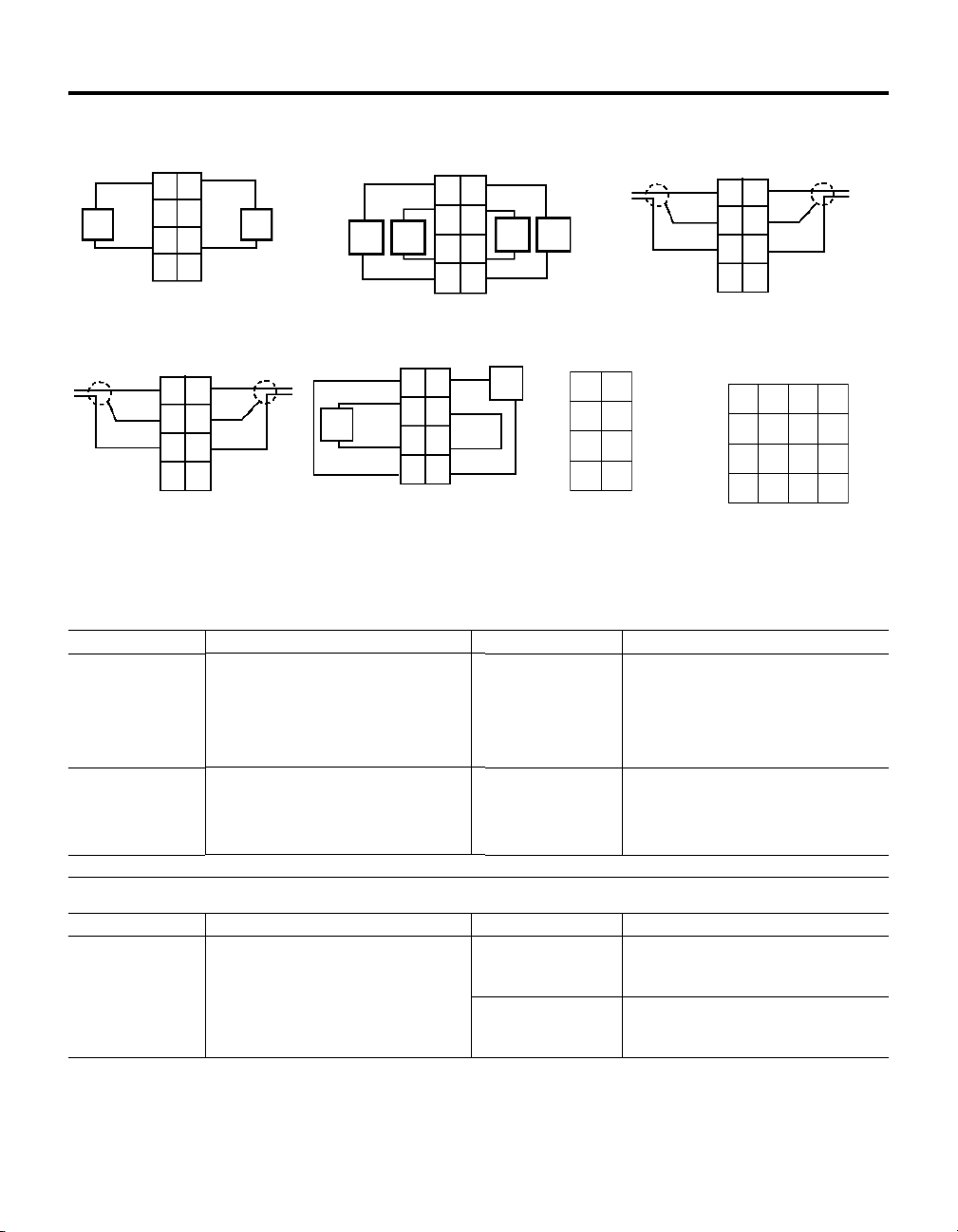
1734-IV2
1
0
In 0 In 1
3
2
NC
Prox
V = 12/24V dc, C = Common
Field power is supplied from power bus
NC
4
C
C
6
VV
IV2 Source Input
Prox
5
7
41968
Publication 1734-IN510B-EN-P - August 2000
1734-IV4
0
In 0 In 1
2
In 2
Prox
V = 12/24V dc, C = Common
Field power is supplied from power bus
In 3
4
C
C
6
VV
IV4 Source Input
1734-OA2
1
1
3
Prox
5
7
ProxProx
41969
Load
Ch 0 = Channel 0 Ch 1 = Channel 1 NC = No Connection
L2/N = 120/220V ac Return L1 = 120/220V ac Supply
Field power is supplied from the internal power bus.
0
Ch 0 Ch 1
2
NC
4
L2/N
L2/N
6
L1 L1
OA2 Output
3
NC
5
7
Load
42014
Page 3
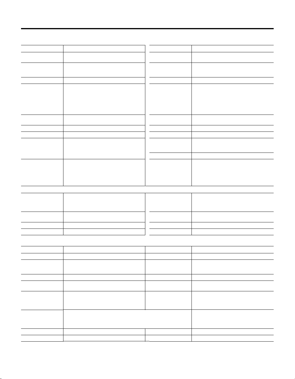
Wiring Diagrams
1734-OB2E
1
0
Out 0Out
1
3
2
Out
Out
1
Load Load
V = 12/24V dc, C = Common
Field power is supplied from power bus
0
4
CC
6
5
7
VV
42014
1734-OE2C
Out 0 Out 1
0
1
Out 0Out
1
2
3
Chass
Chass
Gnd
Gnd
4
5
CC
6
7
VV
V = 12/24V dc, C = Common
Chass GND = Chassis Ground
This supply will be connected to
the internal power bus.
42018
Load Load
Load
V = 12/24V dc, C = Common
This supply will be connected to
the internal power bus.
1734-OB4E
0
1
Out 0Out
1
2
3
Out
Out
3
2
5
7
CC
Load Load
4
CC
6
V = 12/24V dc, C = Common
Field power is supplied from powe r bus
1734-OW2
0
1
Out
Out
0A
2
Out
Out
0B
4
C
6
VV
1A
1B
C
Load
3
5
7
42019
42015
V = 12/24V dc, C = Common Chass GND = Chassis Ground
This supply will be connected to the internal pow er bus.
1734-IJ, & 1734-IK
1
0
AAnot
3
2
B
Bnot
5
4
Z
Znot
7
6
FE FE
A, B, Z, Anot, Bnot,
and Znot = inputs
FE = Functional Earth
41975
1734-IE2C
In 0 In 1
0
2
Chass
Gnd
4
6
Specifications
General specifications - These specifications are shared by all components of the 1734 POINT I/O system.
Specification: Value: Specification: Value:
Environ. Conditions
Operating Temp.
Storage Temp.
Relative Humidity
Shock Operating
Non-operating
Vibration
Terminal Base Screw
Torque
1
Use this conductor category information for planning conductor routing as described in the system level installation manual.
30g peak acceleration, 11(±1)ms pulse width
50g peak acceleration, 11(±1)ms pulse width
Tested 5g @ 10-500Hz per IEC 68-2-6
o
-20 to 55
C (-4 to 131oF)
o
C (-40 to 185oF)
-40 to 85
5 to 95% noncondensing
7 inch-pounds max Agency Certification
Conductors
Wire Size
Category
(When Product or
Packaging is Marked)
14 AWG (2.5mm
(18 AWG max if connecting 2 wires to same terminal)
CE marked for all applicable directives
C-Tick marked for all applicable acts
CUL listed – Class I, Division 2
CUL recognized
DeviceNet conformance tested
solid or stranded max
3/64 inch (1.2mm) insulation max
Groups A, B, C and D certified
POINT I/O 3
1
In 0In
1
3
Chass
Gnd
5
CC
7
VV
42017
1734-VHSC24, &
1734-VHSC5
0
1
0
FE FE
2
RET 0
RET 1
4
-Vaux -Vaux
6
+Vaux +Vaux
1
3
5
7
42444
A Anot
2
3
B
Bnot
4
5
Z
Znot
6
7
Out 0 Out 1
A, B, Z, Anot, Bnot, and Znot = inputs
FE = Functional Earth
-Vaux = Auxiliary Supply
+Vaux = Auxiliary Supply
2
) - 22 AWG (0.25mm2)
1
2
1734-TB, -TBS, -TB3 and -TB3S Specifications
Specification: 1734-TB, -TBS, -TB3, -TB3S Specification: 1734-TB, -TBS, -TB3, -TB3S
Field Power Bus
Voltage 240V ac (1734-TB, -TBS)
28.8V dc, 120/240V ac (1734-TB3, -TB3S)
Current 10A max Mass 2.94 oz/83.35 grams (1734-TB)
Dimensions
(HxWxL)
65mm x 12mm x 133.4mm
(2.560in x 0.472in x 5.250in) (1734-TB, -TBS)
65mm x 12mm x 160mm
(2.560in x 0.472in x 6.25in) (1734-TB3, -TB3S)
2.57 oz/73.86 grams (1734-TBS)
3.44 oz/97.5 grams (1734-TB3)
3.07 oz/87 grams (1734-TB3S)
Publication 1734-IN510B-EN-P - August 2000
Page 4
4 POINT I/O
1734-ADN Specifications
Specification Value Specification Value
Expansion I/O Capacity 12 modules (Note: Total expansion up to 63 modules
DeviceNet Communication
Rate
Module Location Starter module - left side of 1734 system Input Voltage Rating 24V dc nominal
Power Supply Note: In order to comply with CE Low Voltage
DeviceNet Input Voltage
Range
Power Consumption 8.1W maximum @ 28.8V dc Isolation Voltage 1250V rms/V ac
Power Dissipation 2.8W maximum @ 28.8V Thermal Dissipation 9.5 BTU/hr maximum @ 28.8V dc
Field Power Bus
Nominal Voltage
Supply Voltage Range
Supply Current 10A maximum Mass 9.0 oz/255 grams
Field Wiring Terminations
DeviceNet 1 - Black Wire V
with 1734-EP24DC)
125K bit/s (500m maximum)
250K bit/s (250m maximum)
500K bit/s (100m maximum)
Directives (LVD), you must use a Safety Extra Low
Voltage (SELV) or a Protected Extra Low Voltage (PELV)
power supply to power this adapter.
11-25V dc DeviceNet specification DeviceNet Power
24V dc
10-28.8V dc range,
2 - Blue Wire CAN Low
3 - Bare Wire Shield
4 - White Wire CAN High
5 - Red Wire +V
Power Supply Specifications
Power Supply Note: In order to comply with CE Low Voltage
Input Voltage Rating 24V dc nominal
Inrush Current 6A maximum for 10ms PointBus Output Current 1A maximum @ 5V dc ±5% (4.75 - 5.25)
Input Overvoltage Protection
Directives (LVD), you must use a Safety Extra Low
Voltage (SELV) or a Protected Extra Low Voltage (PELV)
power supply to power this adapter.
10-28.8V dc range
Reverse polarity protected
Input Overvoltage
Protection
DeviceNet Cable Allen-Bradley part number 1485C-P1-Cxxx
Indicators 3 red/green status indicators
Requirements
Dimensions Inches
(Millimeters)
Field Wiring Terminations
Power Supply
Interruption Output voltage will stay within specifications when
Field Side Power
Requirements
Reverse polarity protected
Refer to publication DN-2.5 for more information
Adapter status
DeviceNet status
PointBus status
2 green power supply status indicators:
System Power (PointBus 5V power)
Field Power (24V from field supply)
24V dc (+4% = 25V dc max) @ 30mA maximum
3.0H x 2.16W x 5.25L
(76.2H x 54.9W x 133.4L)
0 - No Connection 1 - No Connection
2 - Chassis Ground 3 - Chassis Ground
4 - Common 5 - Common
6 - Supply 7 - Supply
input drops out for 10ms at 10V with maximum load.
24V dc (+20% = 28.8V dc maximum) @ 400mA
maximum
1734-PDN Specifications
Specification Value: Specification Value:
Expansion I/O Capacity 12 modules Module Location Starter module - left side of 1734 system
Communication Rate 125K bits/s (500m max)
DeviceNet Power Req. 24V dc (+4% = 25V dc max @ 400mA max Dimensions (HxWxL) 76.2mm x 25.4mm x 133.4mm (3.0in x 1.0in x 5.25in)
DeviceNet Cable Allen-Bradley PN 1485C-P1-Cxxx
Power Supply Note: In order to comply with CE Low Voltage
Field Wiring
Power Supply
Input Voltage Rating 24V dc nominal Power Dissipation 1.2W max @ 25V
Input Voltage Range 11-25V dc DeviceNet specification Thermal Dissipation 4.1 BTU/hr max @ 25V dc
250K bits/s (250m max)
512K bits/s (100m max)
Refer to publication DN-2.5
Directives (LVD), you must use a Safety Extra Low
Voltage (SELV) or a Protected Extra Low Voltage (PELV)
power supply to power this interface.
0 - No connection 4 - Common
1 - No connection 5 - Common
2 - Ground 6 - Supply
3 - Ground 7 - Supply
Indicators 2 green power supply status indicators
Input Overvoltage
Protection
Field Power Bus
Voltage
Current
Field Wiring Terminations
DeviceNet
System power (PointBus 5V power)
DeviceNet power (24V from DeviceNet)
Reverse polarity protected
10V to 28.8V dc,
120V ac or 240V ac
10A max
1 - Black -V 4 - White CAN High
2 - Blue CAN Low 5 - Red +V
3 - Bare Drain
Publication 1734-IN510B-EN-P - August 2000
Page 5

Specification Value: Specification Value:
Inrush Current 6A for 5ms Power Consumption 7.0W max @ 25V dc
Pointbus Output Current 1A maximum @ 5V dc +
Isolation Voltage 1528V rms/V ac
5% (4.75-5.25) Mass 4.56 oz/129.28 grams
POINT I/O 5
1734-FPD Specifications
Specification Value: Specification Value:
Pointbus Output Current Pass through Indicators None
Input Current 10A max Inrush Current 10A max
Module Location Between I/O modules in 1734 system
Field Power Bus
Volt age
Current
Input Voltage Rating 12V dc, 24V dc, 120V ac, 240V ac nominal Mass 4.38 oz/124.17 grams
Breaks power bus
264V ac max
12V dc, 24V dc/120V ac or 240V ac
10A max
Dimensions
(HxWxL)
Power Supply 0 - No connection 4 - Common
76.2mm x 25.4mm x 133.4mm
(3.00in x 1.00in x 5.25in)
1 - No connection 5 - Common
2 - Ground 6 - Supply
3 - Ground 7 - Supply
1734-AC Input Modules (1734-IA21, -IM22)
Specification Value Specification Value
Module Location 1734-TB, -TBS, -TB3 or -TB3S wiring base assembly Pointbus Current 75mA maximum @ 5V dc
Power Dissipation 0.7W maximum @ 28.8V dc Thermal Dissipation 2.4 BTU/hr maximum @ 28.8V dc
Isolation Voltage Tested at 1250V rms/V for 1s (1734-IA2)
External AC Power Supply
Volt age
Field Wiring Terminations 0 - Input 0 1 - Input 1
Tested at 1500V rms/V for 1s (1734-IM2)
120V ac, 60Hz nominal (1734-IA2)
220V ac, 60Hz nominal (1734-IM2)
2 - No Connection 3 - No Connection
4 - L2N 5 - L2/N
6 - L1 7 - L1
Input Specifications (1734-IA2, -IM2)
Number of Inputs 2 (1 group of 2) non-isolated, sinking OFF-State Voltage 43V ac maximum
ON-State Voltage 1734-IA2
OFF-State Current 2.5mA maximum (1734-IA2)
3
Delay Time
OFF to ON and
ON to OFF
Keyswitch Position 8
65V ac minimum 159V ac minimum
120V ac nominal 220V ac nominal
2.9mA maximum (1734-IM2)
20ms hardware filter plus 1ms - 64ms digital filter
programmable in increments of 1ms
1734-IM2
Dimensions Inches
(Millimeters)
External AC Power Supply
Voltage Range
Mass 1.09 oz/30.90 grams
ON-State Current 1734-IA2
Nominal Input Impedance 10.6kΩ (1734-IA2)
Indicators 2 yellow input status, logic side
1
This module is IEC3 120V ac input compliant.
2
This module is IEC3 220V ac input compliant.
3
Off/on delay is time from a valid out put “on” signal to output energization. On/off delay is time
from a valid output “off” signal to ou tput deenergization.
2.21H x 0.47W x 2.97L
(56.0H x 12.0W x 75.5L)
85-132V ac, 47-63Hz (1734-IA2)
159-264V ac, 47-63Hz (1734-IM2)
3.7mA minimum 5.7mA minimum
6.9mA nominal @ 120V ac, 60Hz 8.0mA nominal
22.3kΩ (1734-IM2)
1 green/red network status, logic side
1 green/red module status, logic side
1734-IM2
Publication 1734-IN510B-EN-P - August 2000
Page 6

6 POINT I/O
1734-AC Output Modules1 (1734-OA2)
Specification Value Specification Value
Module Location 1734-TB, TBS, TB3 or -TB3S wiring base assembly Pointbus Current 75mA maximum @ 5V dc
Power Dissipation 0.8W maximum @ 28.8V dc Thermal Dissipation 2.7 BTU/hr maximum @ 28.8V dc
Isolation Voltage Tested at 1500V rms/V ac dc for 1s Mass 1.09 oz/30.9 grams
External AC Power Supply
Volt age
Dimensions Inches
(Millimeters)
Output Specifications
Outputs per Module 2 non-isolated, sourcing ON-State Voltage Drop 1.0V maximum @ 0.75A
ON-State Voltage Range 74V ac minimum
ON-State Current 10mA minimum per channel
OFF-State Leakage 2.7mA max Output Current Rating 1.5A (2 channels @ 0.75A each)
Surge Current 16A for 100ms, repeatable every 10s Keyswitch Position 8
1
This module is IEC3 120V/220V ac Output Compliant
1
Off/on delay is time from a valid output “on” signal to output energization. On/off delay is time from a valid output “off” signa l to output deenergization.
1734 DC Input Sink Modules
Specification: Value: Specification: Value:
Module Location 1734-TB or -TBS terminal base unit Pointbus Current 75mA max @ 5V dc
Inputs/Module 2 (1 group of 2) non-isolated, sinking (1734-IB2)
ON-State Voltage 10V dc min
OFF-State Voltage 5V dc max OFF-State Current 1.5mA min
Input Impedance 5.3K Ω max Keyswitch Position 1
Indicators 2 yellow input status, logic side (1734-IB2)
Power Dissipation 0.7W max @ 28.8V dc (1734-IB2)
Field Power
Supply Voltage
Voltage Range
Dimensions (HxWxL) 56mm x 12mm x 75.5mm (2.206in x 0.472in x 2.97in) Mass 1.09 oz/30.90 grams - (1734-IB2)
1
1734-IB2 and -IB4 specifications are IEC 1+ 24V dc input compliant
2
Input OFF to ON, and ON to OFF, filter time is the time from a valid input signal to recognition by the module.
120/220V ac, 60Hz nominal External AC Power Supply
2.21H x 0.47W x 2.97L
(56.0H x 12.0W x 75.5L)
120/220V ac nominal
264V ac maximum
750mA maximum per channel
1
(1734-IB2, -IB4)
4 (1 group of 4) non-isolated, sinking (1734-IB4)
24V dc nominal
28.8 V dc max
4 yellow input status, logic side (1734-IB4)
1 green/red network status, logic side
1 green/red module status, logic side
0.9W max @ 28.8V dc (1734-IB4)
24V dc nominal
10-28.8V dc
Voltage Range
Field Wiring Terminations 0 - Output 0 1 - Output 1
2
Delay Time
OFF to ON
ON to OFF
Indicators (field side
indication, logic driven)
Input Filter Time
ON-State Current 2mA min
Power Supply 0 - Input 0 6 - Supply
Thermal Dissipation 2.4 BTU/hr max @ 28.8V dc (1734-IB2)
Isolation Voltage 1250V rms/V ac
2
85-264V ac, 47-63Hz
2 - No Connection 3 - No Connection
4 - L2N Return 5 - L2/N Return
6 - L1 7 - L1
1/2 cycle maximum
1/2 cycle maximum
2 yellow status
2 green/red status
OFF to ON: 0-65ms (1ms default)
ON to OFF: 0-65ms (1ms default)
4mA nominal @ 24V dc
5mA max
1 - Input 1 7 - Supply
2 - No Conn. (1734-IB2) - Input 2 1734-IB4)
3 - No Conn. (1734-IB2) - Input 3 (1734-IB4)
4 - Common (1734-IB2) - User Supply (1734-IB4)
5 - Common (1734-IB2) - User Supply (1734-IB4)
3.1 BTU/hr max @ 28.8V dc (1734-IB2)
1.12 oz/31.75 grams - (1734-IB4)
Publication 1734-IN510B-EN-P - August 2000
Page 7

POINT I/O 7
1734 DC Input Source Modules1 (1734-IV2, -IV4,)
Specification: Value: Specification: Value:
Module Location 1734-TB or -TBS terminal base unit Pointbus Current 75mA max @ 5V dc
Inputs/Module 2 (1 group of 2) non-isolated, sourcing (1734-IV2)
ON-State Voltage 10V dc min
OFF-State Voltage 5V dc max OFF-State Current 1.5mA min
Input Impedance 5.3K Ω max Keyswitch Position 1
Power Dissipation 0.7W max @ 28.8V dc (1734-IV2)
Field Power
Supply Voltage
Voltage Range
Indicators 2 yellow input status, logic side (1734-IV2)
Dimensions (HxWxL) 56mm x 12mm x 75.5mm (2.206in x 0.472in x 2.97in) Mass 1.10 oz/31.19 grams - (1734-IV2)
1
1734-IV2 and -IV4 specifications are IEC 1+ 24V dc input compliant.
2
Input OFF to ON, and ON to OFF, filter time is the time from a valid input signal to recognition by the module.
4 (1 group of 4) non-isolated, sourcing (1734-IV4)
24V dc nominal
28.8 V dc max
0.9W max @ 28.8V dc (1734-IV4)
24V dc nominal
10-28.8V dc
4 yellow input status, logic side (1734-IV4)
1 green/red network status, logic side
1 green/red module status, logic side
Input Filter Time
ON-State Current 2mA min
Thermal Dissipation 2.4 BTU/hr max @ 28.8V dc (1734-IV2)
Isolation Voltage 1250V rms/V ac
Power Supply 0 - Input 0 4 - Common
2
OFF to ON: 0-65ms (1ms default)
ON to OFF: 0-65ms (1ms default)
4mA nominal @ 24V dc
5mA max
3.1 BTU/hr max @ 28.8V dc (1734-IV4)
1 - Input 1 5 - Common
2 - No Conn. (1734-IV2) 6 - Supply (1734-IV2)
Input 2 (1734-IV4) Common (1734-IV4)
3 - No Conn. (1734-IV2) 7 - Supply (1734-IV2)
Input 3 (1734-IV4) Common (1734-IV4)
1.12 oz/31.75 grams - (1734-IV4)
1734 DC Electronically Protected Output Modules (1734-OB2E, -OB4E)
Specification: Value: Specification: Value:
Module Location 1734-TB or -TBS terminal base unit Pointbus Current 75mA max @ 5V dc
Number of Outputs 2 (1734-OB2E) - 4 (1734-OB4E) nonisolated, sourcing Keyswitch Position 1
ON-State Current 1.0mA min/channel OFF-State Voltage 28.8V dc max
ON-State
Voltage Range
ON-State Voltage Drop 0.2V dc max OFF-State Leakage 0.5mA max
Output Current Rating Max 1.0A/output
Surge Current 2A for 10ms, repeatable every 3s Isolation Voltage 1250V rms/V ac
Power Dissipation 0.8W max @ 28.8V dc - (1734-OB2E)
Field Wiring Terminations 0 - Output 0
1
OFF to ON delay is time from a valid output ON signal to output energization. ON to OFF delay is time from a valid output OFF signal to output deenergization.
10V dc min
24V dc nominal
28.8V dc max
2.0 max/module (1734-OB2E)
4.0 max/module (1734-OB4E)
1.2W max @ 28.8V dc - (1734-OB4E)
1 - Output 1
2 - Output 0 (1734-OB2E) - Output 2 (1734-OB4E)
3 - Output 1 (1734-OB2E) - Output 3 (1734-OB4E)
4 - Common
5 - Common
6 - Supply (1734-OB2E) - Common (1734-OB4E)
7 - Supply (1734-OB2E) - Common (1734-OB4E) Mass 1.15 oz/32.60 grams (1734-OB2E)
Output Signal Delay
OFF to ON
ON to OFF
Dimensions
(HxWxL)
Thermal Dissipation 2.7 BTU/hr max @ 28.8V dc - (1734-OB2E)
External dc Power
Supply Voltage
Voltage Range
Indicators (Field side
indication, logic driven)
1
0.1ms max
0.1ms max
56mm x 12mm x 75.5mm
(2.206in x 0.472in x 2.97in)
4.1 BTU/hr max @ 28.8V dc - (1734-OB4E)
24V dc nominal
10 - 28.8V dc
2 yellow status (1734-OB2E) - 4 yellow status (1734-OB4E)
2 red fault (1734-OB2E) - 4 red fault (1734-OB4E)
2 green/red status
1.17 oz/33.43 grams (1734-OB4E)
Publication 1734-IN510B-EN-P - August 2000
Page 8

8 POINT I/O
1734 Analog Modules (1734-IE2C, -OE2C)
Specification: 1734-IE2C Value: 1734-OE2C Value: Specification: 1734-IE2C Value: 1734-OE2C Value:
Module Location 1734-TB or -TBS terminal base unit Pointbus Current 75mA max @ 5V dc
Inputs/Module 2 single-ended,
Input Current Terminal 4-20mA
Output Current Terminal 0mA Output until module
non-isolated
0-20mA
is configured
4-20mA user configurable
0-20mA user configurable
Number of Outputs 2 single-ended,
non-isolated
Keyswitch Position 3 4
Resolution
Current
16 bits - over 21mA
1.28μA/cnt, 0.32μA/cnt
13 bits over 21mA
2.56μA/cnt
Data Format Signed Integer Calibration Factory Calibrated
Conversion Type Delta Sigma Digital to Analog
Conversion Rate
External dc Power
Supply Voltage
Voltage Range
Supply Current
Field Wiring Terminations 0 - Input 0 4 - Common
Absolute Accuracy
60ms/channel @ Notch = 50Hz
50ms/channel @ Notch = 60Hz
12ms/channel @ Notch = 250Hz
6ms/channel @ Notch = 500Hz
24V dc nominal
10-28.8V dc
10mA @ 24V dc
1 - Input 1 5 - Common
2 - Ground 6 - Supply
3 - Ground 7 - Supply
1
0.1% of Full Scale @ 25°C 0.3% of Full Scale @ 25°C Accuracy Drift w/Temp. 30ppm/°C
convertor
Digital to Analog
convertor
24V dc nominal
10-28.8V dc (includes 5%
ac ripple)
50mA @ 24V dc (including
outputs @ 20mA)
0 - Output 0 4 - Common
1 - Output 1 5 - Common
2 - Ground 6 - Supply
3 - Ground 7 - Supply
Common Mode Rejection
Ration
Step Response to 63% of
Full Scale
Step Response to Current
Ter mi na l
Normal Mode Rejection
Ration
120dB
Notch Filter
60Hz 70ms
50Hz 80ms
250Hz 16ms
500Hz 8ms
-60dB
-3dB
Notch filter
13.1Hz @ Notch = 50Hz
15.7Hz @ Notch = 60Hz
65.5Hz @ Notch = 250Hz
131Hz @ Notch = 500Hz
24μs
Maximum Overload Fault protected to 28.8V dc Resist. Load on mA Output 0-330Ω
Indicators 4 green/red indicators Mass 1.22 oz/34.59 grams 1.26 oz/25.72 grams
Power Dissipation 0.5W max @ 28.8V dc 1.0W max @ 28.8V dc Thermal Dissipation
Isolation Voltage 1250V rms/V ac
1
Includes offset, gain, non-linearity and repeatability error terms.
No isolation between individual channels
Dimensions
(HxWxL)
1.7 BTU/hr max @ 28.8V dc 3.4 BTU/hr max @ 28.8V dc
56mm x 12mm x 75.5mm
(2.206in x 0.472in x 2.97in)
1734 Relay Module (1734-OW2)
Specification: Value: Specification: Value:
Module Location 1734-TB or -TBS terminal base unit Pointbus Current 80mA max @ 5V dc
1
Number of Outputs
OFF-State Leakage 1.2mA (max @ 240V ac)
Output Voltage Range
(load dependent)
Output Current Rating (at
rated power)
2 Form A isolated (normally open) electromechanical relays
Bleed resistor through snubber circuit
5-28.8V dc @ 2.0A resistive
48V dc @ 0.5A resistive
125V dc @ 0.25A resistive
125V ac @ 2.0A resistive
240V ac @ 2.0A resistive
Resistive
2A @ 5-28.8V dc 2A @ 125V ac
0.5A @ 48V dc 2A @ 240V ac
0.25A @ 125V dc
Inductive
2A steady state @ 5-30V dc, L/R = 7ms
0.5A steady state @ 48V dc, L/R = 7ms
0.25A steady state @ 125V dc, L/R = 7ms
2A steady state, 15A make @ 125V ac, PF = cos θ = 0.4
2A steady state, 15A make @ 240V ac, PF = cos θ = 0.4
Keyswitch Position 7
Output Signal Delay OFF to ON - 8ms max
Power Supply 0 - Output 0A 4 - Common
Power Rating (steady
state)
ON to OFF - 26ms max
1 - Output 1A 5 - Common
2 - Output 0B 6 - Supply
3 - Output 1B 7 - Supply
250W max for 125V ac resistive output
480W max for 240V ac resistive output
60W max for 28.8V dc resistive output
24W max for 48V dc resistive output
31W max for 125V dc resistive output
250VA max for 125V ac inductive output
480VA max for 240V ac inductive output
60VA max for 30V dc inductive output
24VA max for 48V dc inductive output
31VA max for 125V dc inductive output
Publication 1734-IN510B-EN-P - August 2000
Page 9

Specification: Value: Specification: Value:
Isolation Voltage
Between any 2 sets
of contacts
Customer load to logic
Initial Contact Resistance 30mΩ Operate/Release Time 10ms max
Switching Frequency 1 operation/3s (0.3Hz at rated load) max Bounce Time 1.2ms (mean)
Min. Contact Load 100μA at 100mV dc Mass 1.30 oz/36.86 grams
Expected Life of Electrical
Contacts
Power Dissipation 0.5W max @ 28.8V dc Thermal Dissipation 1.7 BTU/hr max @ 28.8V dc
Dimensions (HxWxL) 56mm x 12mm x 75.5mm (2.206in x 0.472in x 2.97in)
1
Module outputs are not fused. If external fusing is desired, you must provide external fusing.
2550V dc for 1s
2550V dc for 1s
Min 100,000 operations @ rated loads Indicators 2 green/red module/network status
Field Power
Supply Voltage
Voltage Range
Supply Current
None required
240V ac max
2A/channel max 4A/module
2 yellow output status
1734-Counter Modules (1734-IJ, -IK)
Specification Value Specification Value
Number of Inputs 1 - 1 group of A/Areturn, B/Breturn and Z/Zreturn Input Voltage 5V (1734-IJ)
Input Current 19.1mA @ 5V dc (1734-IJ); 6.1mA @ 15V dc (1734-IK)
Input OFF-State Current <
Input OFF-State Voltage <
Input Filter Selections (per
A/B/Z group)
Module Location 1734-TB, -TBS, -TB3, -TB3S wiring base assembly Pointbus Current 160mA maximum
Keyswitch Position 2 Mass 1.15 oz/32.60 grams
Thermal Dissipation 3.75 BTU/hr maximum @ rated load (1734-IJ)
Isolation Voltage
(minimum)
External dc Power No additional external power required to power
25.7mA @ 6V dc (1734-IJ);10.2mA @ 24V dc (1734-IK)
0.250mA max Input ON-State Current >5mA
1.25V dc (1734-IJ) / <1.8V dc (1734-IK) Input ON-State Voltage >2.6V dc (1734-IJ); >12.5V dc (1734-IK)
Off
10μs
100μs
1.0ms
10.0ms
5.1 BTU/hr maximum @ rated load (1734-IK)
Prequalified at 1250V ac/rms between:
System side
Chassis ground
A/B/Z inputs
module.
Maximum ON-State
Voltage
Maximum Input Frequency 1.0MHz counter and encoder X1 configurations
Power Dissipation 1.1W maximum @ rated load (1734-IJ)
Field Wiring Terminations 0 - A 1 - Aret
DimensionsInches
(Millimeters)
15-24V dc (1734-IK)
+
6V (1734-IJ)
For 1734-IK, see pub. 1734-TD002A-EN-P
500kHz encoder X2 configuration (no filter)
250kHz encoder X4 configuration (no filter)
1.5W maximum @ rated load (1734-IK)
2 - B 3 - Bret
4 - Z 5 - Zret
6 - Chassis ground 7 - Chassis ground
2.21H x 0.47W x 2.97L
(56.0H x 12.0W x 75.5L)
POINT I/O 9
1734-Very High Speed Counter Modules (1734-VHSC24, -VHSC5)
Specification Value Specification Value
Module Location 1734-TB, -TBS, -TB3, -TB3S wiring base assembly Keyswitch Position 2
Pointbus Current 180mA maximum Field Power Bus 24V dc nominal; range 10-28.8V dc
Power Dissipation 1.9W maximum @ rated load (1734-VHSC24)
Isolation Voltage
(minimum)
External dc Power (does
not represent power
required to supply outputs)
1.5W maximum @ rated load (1734-VHSC5)
Prequalified for 1250V ac/rms between:
Module 1
System side (PointBus)
Chassis ground
A/B/Z inputs
O0/O1 and user power supply
Module 2
System side
Chassis ground
Vaux +
User power supply common
No additional external power required to
power module
Thermal Dissipation 6.5 BTU/hr maximum @ rated load (1734-VHSC24)
Field Wiring Terminations Module 1
Dimensions Inches
(Millimeters)
5.1 BTU/hr maximum @ rated load (1734-VHSC5)
0 - A 1 - Aret
2 - B 3 - Bret
4 - Z 5 - Zret
6 - Output 0 7 - Output 1
Module 2
0 - Chassis ground 1 - Chassis ground
2 - Return 0 3 - Return 1
4 - -V 5 - -V
6 - +V 7 - +V
2.21H x 0.47W x 2.97L
(56.0H x 12.0W x 75.5L)
Publication 1734-IN510B-EN-P - August 2000
Page 10

10 POINT I/O
Mass 1.15 oz/32.60 grams
Input Specifications
Number of Inputs 1 - 1 group of A/Areturn, B/Breturn and Z/Zreturn Maximum Input Frequency 1.0MHz counter and encoder X1 configurations
Input Voltage 15-24V dc(1734-VHSC24)
Input Current 6.1mA @ 15V dc (1734-VHSC24)
Input OFF-State Current <
Input ON-State Current >
5V dc (1734-VHSC5)
10.2mA @ 24V dc (1734-VHSC24)
19.1mA @ 5V dc (1734-VHSC5)
25.7mA @ 6V dc (1734-VHSC5)
0.250mA max Input OFF-State Voltage <1.8V dc (1734-VHSC24); <1.25V dc (1734-VHSC5)
5mA Input ON-State Voltage >12.5V dc (1734-VHSC24); >2.6V dc (1734-VHSC5)
Maximum ON-State
Voltage
Input Filter Selections Off
Output Specifications (1734-VHSC24, -VHSC4)
Number of Outputs 1 isolated group of 2 capable of 0.5A @ 24V dc Output Control Outputs can be tied to any of 4 compare windows
Output Supply Volt. Range 10-28.8V dc ON-State Current 0.5A maximum
OFF-State Leakage Current <
Short Circuit Current 6A - Outputs are short circuit protected and either
ON-State Voltage Drop <
0.5mA Open Wire Detection Open wire detected when output is turned off
1
cycle until the fault is corrected, or latch off
(depending upon programming)
Short circuit detected when output is turned on.
0.3V dc @ 0.5A
Delay Time
OFF to ON
ON to OFF
1 Off/on delay is time from a valid output “on” signa l to output energization. On/off delay is time
from a valid output “off” signal to ou tput deenergization.
500kHz encoder X2 configuration (no filter)
250kHz encoder X4 configuration (no filter)
For 1734-VHSC24, see pub. 1734-TD002A-EN-P
+
6V (1734-VHSC5)
10μs
100μs
1.0ms
10.0ms
25μs (load dependent)
150μs (load dependent)
Publication 1734-IN510B-EN-P - August 2000
Page 11

European Communities (EC) Directive Compliance
If this product has the CE mark it is approved for installation within
the European Union and EEA regions. It has been designed and tested
to meet the following directives.
EMC Directive
This product is tested to meet the Council Directive 89/336/EC Electromagnetic Compatibility (EMC) by applying the following standards, in
whole or in part, documented in a technical construction file:
• EN 50081-2 EMC — Generic Emission Standard, Part 2 —
Industrial Environment
• EN 50082-2 EMC — Generic Immunity Standard, Part 2 —
Industrial Environment
This product is intended for use in an industrial environment.
Low Voltage Directive
This product is tested to meet Council Directive 73/23/EEC Low
Voltage, by applying the safety requirements of EN 61131-2
Programmable Controllers, Part 2 - Equipment Requirements and
Tests. For specific information required by EN 61131-2, see the
appropriate sections in this publication, as well as the Allen-Bradley
publication Industrial Automation Wiring and Grounding Guidelines
For Noise Immunity, publication 1770-4.1.
This equipment is classified as open equipment and must be mounted
in an enclosure during operation to provide safety protection.
POINT I/O 11
Publication 1734-IN510B-EN-P - August 2000
Page 12

Publication 1734-IN510B-EN-P - August 2000 PN 957395-13
Supersedes Publication 1734-5.10 - September 1999 © 2000 Rockwell International Corporation. Printed in Singapore.
 Loading...