

Page 1

User Manual
1732E ArmorBlock Dual-Port EtherNet/IP 4-Point
Analog Input and Output Modules
Catalog Numbers
1732E-IF4M12R, 1732E-OF4M12R
Page 2
Important User Information
IMPORTANT
Solid-state equipment has operational characteristics differing from those of electromechanical equipment. Safety
Guidelines for the Application, Installation and Maintenance of Solid State Controls (publication SGI-1.1
your local Rockwell Automation sales office or online at http://www.rockwellautomation.com/literature/
important differences between solid-state equipment and hard-wired electromechanical devices. Because of this difference,
and also because of the wide variety of uses for solid-state equipment, all persons responsible for applying this equipment
must satisfy themselves that each intended application of this equipment is acceptable.
In no event will Rockwell Automation, Inc. be responsible or liable for indirect or consequential damages resulting from
the use or application of this equipment.
The examples and diagrams in this manual are included solely for illustrative purposes. Because of the many variables and
requirements associated with any particular installation, Rockwell Automation, Inc. cannot assume responsibility or
liability for actual use based on the examples and diagrams.
No patent liability is assumed by Rockwell Automation, Inc. with respect to use of information, circuits, equipment, or
software described in this manual.
Reproduction of the contents of this manual, in whole or in part, without written permission of Rockwell Automation,
Inc., is prohibited.
Throughout this manual, when necessary, we use notes to make you aware of safety considerations.
WARNING: Identifies information about practices or circumstances that can cause an explosion in a hazardous
environment, which may lead to personal injury or death, property damage, or economic loss.
available from
) describes some
ATTENTION: Identifies information about practices or circumstances that can lead to personal injury or death,
property damage, or economic loss. Attentions help you identify a hazard, avoid a hazard, and recognize the
consequence
SHOCK HAZARD: Labels may be on or inside the equipment, for example, a drive or motor, to alert people that
dangerous voltage may be present.
BURN HAZARD: Labels may be on or inside the equipment, for example, a drive or motor, to alert people that
surfaces may reach dangerous temperatures.
Identifies information that is critical for successful application and understanding of the product.
Allen-Bradley, Rockwell Software, Rockwell Automation, and TechConnect are trademarks of Rockwell Automation, Inc.
Trademarks not belonging to Rockwell Automation are property of their respective companies.
Page 3

Preface
Read this preface to familiarize yourself with the rest of the manual. It provides
information concerning:
• who should use this manual
• the purpose of this manual
• related documentation
• conventions used in this manual
Who Should Use this Manual
Purpose of this Manual
Resource Description
1732E ArmorBlock™ Dual-Port EtherNet/IP 4-Point Analog
Modules 1732E-WD003
1732E ArmorBlock Dual-Port EtherNet/IP 4-Point Analog Input
and Output Installation Instructions, publication 1732E-IN006
EtherNet/IP Embedded Switch Technology Application Guide,
publication ENET-AP005
EtherNet/IP Modules in Logix5000 Control Systems User
Manual, publication ENET-UM001
Use this manual if you are responsible for designing, installing, programming, or
troubleshooting control systems that use 1732E ArmorBlock Dual Port
EtherNet/IP Dual-Port 4-Point Analog Input and Output Modules.
This manual is a reference guide for the 1732E-IF4M12R, 1732E-OF4M12R
modules. It describes the procedures you use to install, wire, configure,
troubleshoot, and use your module.
Related Documentation
The following documents contain additional information concerning Rockwell
Automation products. To obtain a copy, contact your local Rockwell Automation
office or distributor.
Information on wiring the ArmorBlock Dual-Port EtherNet/IP 4-Point Analog
Modules (1732E-IF4M12R, 1732E-OF4M12R, 1732E-IT4IM12R,
1732E-IR4IM12R).
Information on installing the ArmorBlock EtherNet/IP module.
A manual on how to install, configure and maintain linear and Device-level
Ring (DLR) networks using Rockwell Automation EtherNet/IP devices with
embedded switch technology.
A manual on how to use EtherNet/IP modules with Logix5000 controllers and
communicate with various devices on the Ethernet network.
Getting Results with RSLogix 5000™, publication
9399-RLD300GR
Allen-Bradley Industrial Automation Glossary, AG-7.1
Common Techniques Used in this Manual
The following conventions are used throughout this manual:
• Bulleted lists such as this one provide information, not procedural steps.
Information on how to install and navigate RSLogix 5000. The guide includes
troubleshooting information and tips on how to use RSLogix 5000 effectively.
A glossary of industrial automation terms and abbreviations.
• Numbered lists provide sequential steps or hierarchical information.
• Italic type is used for emphasis.
Rockwell Automation Publication 1732E-UM005A-EN-E - July 2012 iii
Page 4

Notes:
iv Rockwell Automation Publication 1732E-UM005A-EN-E - July 2012
Page 5

Table of Contents
Preface
Who Should Use this Manual . . . . . . . . . . . . . . . . . . . . . . . . . . . . . . . . . . . . . . iii
Purpose of this Manual . . . . . . . . . . . . . . . . . . . . . . . . . . . . . . . . . . . . . . . . . . . . iii
Related Documentation. . . . . . . . . . . . . . . . . . . . . . . . . . . . . . . . . . . . . . . . iii
Common Techniques Used in this Manual. . . . . . . . . . . . . . . . . . . . . . . . . . iii
Chapter 1
Overview of the 1732E
ArmorBlock Analog Input and
Output Modules
Install Your ArmorBlock
Module
Overview . . . . . . . . . . . . . . . . . . . . . . . . . . . . . . . . . . . . . . . . . . . . . . . . . . . . . . . . . . 1
Module Features . . . . . . . . . . . . . . . . . . . . . . . . . . . . . . . . . . . . . . . . . . . . . . . . . . . 1
Physical Features of Your Modules. . . . . . . . . . . . . . . . . . . . . . . . . . . . . . . . . . . 2
Types of Modules . . . . . . . . . . . . . . . . . . . . . . . . . . . . . . . . . . . . . . . . . . . . . . . . . . 3
Hardware/Software Compatibility . . . . . . . . . . . . . . . . . . . . . . . . . . . . . . . . . . 3
Input and Output Types. . . . . . . . . . . . . . . . . . . . . . . . . . . . . . . . . . . . . . . . . . . . 3
Alarms/Limits . . . . . . . . . . . . . . . . . . . . . . . . . . . . . . . . . . . . . . . . . . . . . . . . . . . . . 3
Process Alarms . . . . . . . . . . . . . . . . . . . . . . . . . . . . . . . . . . . . . . . . . . . . . . . . . 4
Clamping . . . . . . . . . . . . . . . . . . . . . . . . . . . . . . . . . . . . . . . . . . . . . . . . . . . . . . 4
Overrange and Underrange Detection. . . . . . . . . . . . . . . . . . . . . . . . . . . . 4
Digital Filters . . . . . . . . . . . . . . . . . . . . . . . . . . . . . . . . . . . . . . . . . . . . . . . . . . . . . . 5
Chapter Summary. . . . . . . . . . . . . . . . . . . . . . . . . . . . . . . . . . . . . . . . . . . . . . . . . . 5
Chapter 2
Overview . . . . . . . . . . . . . . . . . . . . . . . . . . . . . . . . . . . . . . . . . . . . . . . . . . . . . . . . . . 7
Install the Module. . . . . . . . . . . . . . . . . . . . . . . . . . . . . . . . . . . . . . . . . . . . . . . . . . 7
Set the Network Address. . . . . . . . . . . . . . . . . . . . . . . . . . . . . . . . . . . . . . . . 7
Mount the Module . . . . . . . . . . . . . . . . . . . . . . . . . . . . . . . . . . . . . . . . . . . . . . . . . 8
Wire the Module. . . . . . . . . . . . . . . . . . . . . . . . . . . . . . . . . . . . . . . . . . . . . . . . . 10
Chapter Summary. . . . . . . . . . . . . . . . . . . . . . . . . . . . . . . . . . . . . . . . . . . . . . . . 12
Chapter 3
Configure Your Analog Input
and Output Modules with
RSLogix 5000 Software
Rockwell Automation Publication 1732E-UM005A-EN-E - July 2012 v
Introduction. . . . . . . . . . . . . . . . . . . . . . . . . . . . . . . . . . . . . . . . . . . . . . . . . . . . . 13
Set Up the Hardware . . . . . . . . . . . . . . . . . . . . . . . . . . . . . . . . . . . . . . . . . . . . . 14
Create the Example Application . . . . . . . . . . . . . . . . . . . . . . . . . . . . . . . . . . . 15
Configure Your I/O Module . . . . . . . . . . . . . . . . . . . . . . . . . . . . . . . . . . . . . . 16
RSLogix 5000 Configuration Software . . . . . . . . . . . . . . . . . . . . . . . . . 16
Overview of the Configuration Process through RSLogix 5000. . . . . . . 16
Add a New Bridge and Module to Your RSLogix 5000 Project . . . . . . . 16
Add the Local EtherNet/IP Bridge to the I/O Configuration . . . . 17
Add the I/O module as a child of the 1756-EN2T module . . . . . . . 18
Download the Program to Your Controller . . . . . . . . . . . . . . . . . . . . . . . . 21
Edit Your 1732E-IF4M12R Configuration. . . . . . . . . . . . . . . . . . . . . . . . . 21
General Tab. . . . . . . . . . . . . . . . . . . . . . . . . . . . . . . . . . . . . . . . . . . . . . . . . . 22
Page 6

Table of Contents
Connection Tab . . . . . . . . . . . . . . . . . . . . . . . . . . . . . . . . . . . . . . . . . . . . . . 23
Configuration Tab. . . . . . . . . . . . . . . . . . . . . . . . . . . . . . . . . . . . . . . . . . . . 25
Alarm Configuration Tab . . . . . . . . . . . . . . . . . . . . . . . . . . . . . . . . . . . . . 26
Internet Protocol Tab . . . . . . . . . . . . . . . . . . . . . . . . . . . . . . . . . . . . . . . . 28
Calibration Tab . . . . . . . . . . . . . . . . . . . . . . . . . . . . . . . . . . . . . . . . . . . . . . 30
Edit Your 1732E-OF4M12R Configuration. . . . . . . . . . . . . . . . . . . . . . . . 30
General Tab. . . . . . . . . . . . . . . . . . . . . . . . . . . . . . . . . . . . . . . . . . . . . . . . . . 31
Connection Tab . . . . . . . . . . . . . . . . . . . . . . . . . . . . . . . . . . . . . . . . . . . . . . 33
Configuration Tab . . . . . . . . . . . . . . . . . . . . . . . . . . . . . . . . . . . . . . . . . . . 35
Limits Configuration Tab . . . . . . . . . . . . . . . . . . . . . . . . . . . . . . . . . . . . . 36
Fault/Program Action Tab . . . . . . . . . . . . . . . . . . . . . . . . . . . . . . . . . . . . 38
Internet Protocol Tab . . . . . . . . . . . . . . . . . . . . . . . . . . . . . . . . . . . . . . . . 39
Calibration Tab . . . . . . . . . . . . . . . . . . . . . . . . . . . . . . . . . . . . . . . . . . . . . . 41
Status and Monitoring Tabs. . . . . . . . . . . . . . . . . . . . . . . . . . . . . . . . . . . . . . . 41
Chapter Summary . . . . . . . . . . . . . . . . . . . . . . . . . . . . . . . . . . . . . . . . . . . . . . . . 42
Chapter 4
Configurable Features for the
Analog Input and Output
Modules
Calibrate Your Modules
Overview . . . . . . . . . . . . . . . . . . . . . . . . . . . . . . . . . . . . . . . . . . . . . . . . . . . . . . . . 45
Configurable Features for the 1732E-IF4M12R Input Module . . . . . . . 45
Input Types and Ranges . . . . . . . . . . . . . . . . . . . . . . . . . . . . . . . . . . . . . . . 46
Digital Filters. . . . . . . . . . . . . . . . . . . . . . . . . . . . . . . . . . . . . . . . . . . . . . . . . 46
High Engineering/Low Engineering. . . . . . . . . . . . . . . . . . . . . . . . . . . . 47
Real-time Sampling . . . . . . . . . . . . . . . . . . . . . . . . . . . . . . . . . . . . . . . . . . . 48
Process Alarms . . . . . . . . . . . . . . . . . . . . . . . . . . . . . . . . . . . . . . . . . . . . . . . 48
Configurable Features for the 1732E-OF4M12R Output Module . . . . 48
Output Types and Ranges . . . . . . . . . . . . . . . . . . . . . . . . . . . . . . . . . . . . . 48
High Engineering/Low Engineering. . . . . . . . . . . . . . . . . . . . . . . . . . . . 49
Fault Mode and Program Mode . . . . . . . . . . . . . . . . . . . . . . . . . . . . . . . . 49
Clamping/Limiting . . . . . . . . . . . . . . . . . . . . . . . . . . . . . . . . . . . . . . . . . . . 49
Data Tables . . . . . . . . . . . . . . . . . . . . . . . . . . . . . . . . . . . . . . . . . . . . . . . . . . . . . . 50
Chapter Summary . . . . . . . . . . . . . . . . . . . . . . . . . . . . . . . . . . . . . . . . . . . . . . . . 54
Chapter 5
Overview . . . . . . . . . . . . . . . . . . . . . . . . . . . . . . . . . . . . . . . . . . . . . . . . . . . . . . . . 57
Difference of Calibrating an Input Module and an Output Module. . . 57
Calibrate in Program or Run Mode. . . . . . . . . . . . . . . . . . . . . . . . . . . . . 58
Calibrate the Input Module (1732E-IF4M12R). . . . . . . . . . . . . . . . . . . . . 58
Calibrate the Output Module (1732E-OF4M12R). . . . . . . . . . . . . . . . . . 62
Current Meter Calibrations . . . . . . . . . . . . . . . . . . . . . . . . . . . . . . . . . . . 62
Voltage Meter Calibrations . . . . . . . . . . . . . . . . . . . . . . . . . . . . . . . . . . . . 65
Chapter Summary . . . . . . . . . . . . . . . . . . . . . . . . . . . . . . . . . . . . . . . . . . . . . . . . 68
vi Rockwell Automation Publication 1732E-UM005A-EN-E - July 2012
Page 7

Chapter 6
Table of Contents
Troubleshoot the Modules
Specifications
1732E ArmorBlock Embedded
Web Server
Interpret Status Indicators . . . . . . . . . . . . . . . . . . . . . . . . . . . . . . . . . . . . . . . . 69
Check for Faults . . . . . . . . . . . . . . . . . . . . . . . . . . . . . . . . . . . . . . . . . . . . . . . . . 70
Appendix A
General Specifications . . . . . . . . . . . . . . . . . . . . . . . . . . . . . . . . . . . . . . . . . . . . 73
Input Specifications . . . . . . . . . . . . . . . . . . . . . . . . . . . . . . . . . . . . . . . . . . . . . . 73
Output Specifications . . . . . . . . . . . . . . . . . . . . . . . . . . . . . . . . . . . . . . . . . . . . 74
Environmental Specifications . . . . . . . . . . . . . . . . . . . . . . . . . . . . . . . . . . . . . 74
Certifications . . . . . . . . . . . . . . . . . . . . . . . . . . . . . . . . . . . . . . . . . . . . . . . . . . . . 76
Appendix B
Introduction. . . . . . . . . . . . . . . . . . . . . . . . . . . . . . . . . . . . . . . . . . . . . . . . . . . . . 77
Typical Applications . . . . . . . . . . . . . . . . . . . . . . . . . . . . . . . . . . . . . . . . . . . . . 77
Browser Requirements. . . . . . . . . . . . . . . . . . . . . . . . . . . . . . . . . . . . . . . . . . . . 77
Access the Home Page of the Web Server. . . . . . . . . . . . . . . . . . . . . . . . . . . 78
Log On to the Web Server . . . . . . . . . . . . . . . . . . . . . . . . . . . . . . . . . . . . . . . . 78
Navigate the 1732E ArmorBlock I/O . . . . . . . . . . . . . . . . . . . . . . . . . . . . . . 79
Access Diagnostic Information . . . . . . . . . . . . . . . . . . . . . . . . . . . . . . . . . . . . 79
Access Configuration Information. . . . . . . . . . . . . . . . . . . . . . . . . . . . . . . . . 80
Module Tag Definitions
Index
Appendix C
Module Tags for 1732E-IF4M12R . . . . . . . . . . . . . . . . . . . . . . . . . . . . 81
Module Tags for 1732E-OF4M12R . . . . . . . . . . . . . . . . . . . . . . . . . . . 83
Access the Module Tags . . . . . . . . . . . . . . . . . . . . . . . . . . . . . . . . . . . . . . . . . . 84
Rockwell Automation Publication 1732E-UM005A-EN-E - July 2012 vii
Page 8

Table of Contents
viii Rockwell Automation Publication 1732E-UM005A-EN-E - July 2012
Page 9

Chapter
1
Overview of the 1732E ArmorBlock Analog
Input and Output Modules
Overview
Module Features
This chapter provides an introduction to the features and functionalities of the
1732E ArmorBlock Analog Input and Output Modules, 1732E-IF4M12R and
1732E-OF4M12R. It includes the following sections:
Topic Page
Module Features 1
Physical Features of Your Modules 2
Types of Modules 3
Hardware/Software Compatibility 3
Input and Output Types 3
Alarms/Limits 3
Digital Filters 5
ArmorBlock analog I/O modules are interface modules that convert analog
signals to digital values for inputs and convert digital values to analog signals for
outputs. Controllers can then use these signals for control purposes.
By using the producer/consumer network model, ArmorBlock analog I/O
modules produce information when needed.
Some of the module features are as follows:
• multiple preset ranges of voltage or current inputs/outputs
• process alarms and limits
• overrange and underrange detection
• digital filter for 1732E-IF4M12R
For more information about module features, see Configurable Features for the
Analog Input and Output Modules on page 43.
You must use RSLogix 5000 to configure these features. For a more detailed howto-configure guide, read the chapter, Configure Your Analog Input and Output
Modules with RSLogix 5000 Software on page 13.
Rockwell Automation Publication 1732E-UM005A-EN-E - July 2012 1
Page 10
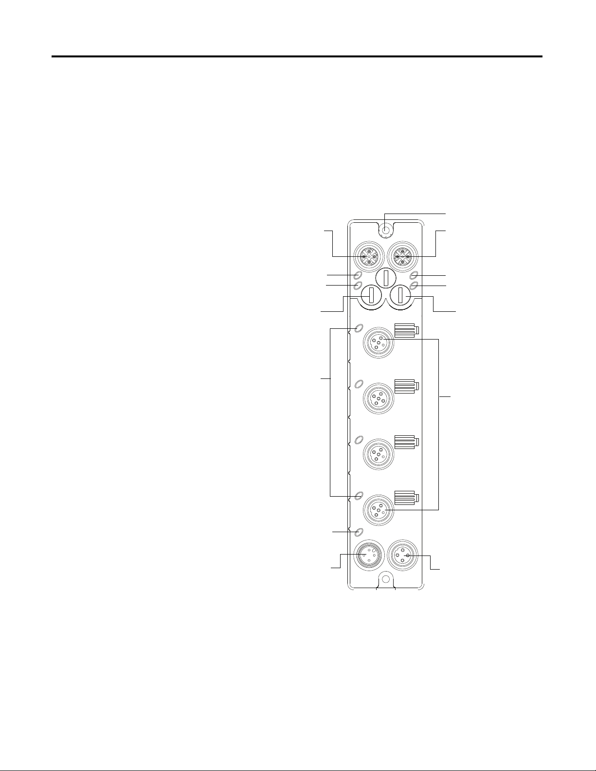
Chapter 1 Overview of the 1732E ArmorBlock Analog Input and Output Modules
45871
Link 1 status indicator
EtherNet/IP D-code
M12 connector
Node address switches
M12 style
I/O connectors
Micro-style power in
Micro-style power out
I/O status
indicators
EtherNet/IP D-code
M12 connector
Link 2 status indicator
Node address switches
Network status indicator
Module status indicator
Auxiliary Power
status indicator
Functional Earth Ground
(1)
Physical Features of Your Modules
The modules have the following components:
• Node address switches
• Connectors (two EtherNet/IP D-code M12 connectors, two micro-style
Power in/out connectors, four I/O M12 connectors)
• Status indicators (Link, I/O, Module, Network, and Auxiliary power
status indicators)
• Functional earth ground
Physical Features of 1732E-IF4M12R and 1732E-OF4M12R Modules
(1)
Functional Earth grounds the I/O block’s EtherNet/IP communication circuitry which is designed to mitigate the
effect of noise on the network. The device requires a solid earth ground connection, either through a metal
screw to a grounded metal panel or through a wire.
2 Rockwell Automation Publication 1732E-UM005A-EN-E - July 2012
Page 11

Overview of the 1732E ArmorBlock Analog Input and Output Modules Chapter 1
Types of Modules
Hardware/Software Compatibility
Input and Output Types
The Analog Input and Output modules are as follows.
Catalog Number Description Network
1732E-IF4M12R 24V DC power, 4-Point Analog Input,
Dual-Port EtherNet/IP Module
1732E-OF4M12R 24V DC power, 4-Point Analog Output,
Dual-Port EtherNet/IP Module
Connector
Dual D-code
M12
Power
Connector
Dual 4-pin
micro
The module and the applications described in this manual are compatible with
the following firmware versions and software releases.
Product Firmware Version / Software Release
1732E-IF4M12R and 1732E-OF4M12R Firmware rev. 1.1 or later
1756-EN2T, 1756-EN2TR, 1756-EN3TR 3.x version when using RSLogix 5000 v20 or later
RSLogix 5000 software 20 or later
RSLinx software 2.56 or later
The 1732E-IF4M12R module supports four input channels, while the
1732E-OF4M12R supports four output channels. Each of the four input/output
channels can be configured as either current or voltage input/output, with
current mode as default configuration.
Alarms/Limits
You can select from a series of operational ranges for each channel. The range
designates the minimum and maximum signals that are detectable by the module.
Input/Output Ranges for 1732E-IF4M12R and 1732E-OF4M12R
Module Input/Output range
1732E-IF4M12R 0…20 mA
1732E-OF4M12R
4…20 mA
0…10 V
-10…10 V
0…5 V
-5…5 V
To use an input or output as a current or voltage device, you must:
• wire the input/output connector for the correct input type (see page 10
)
• configure the input/output as current or voltage via RSLogix 5000
(see page 25
and page 35)
The modules are capable of generating the following alarms:
• process alarms (low, low-low, high, high-high) for 1732E-IF4M12R
• clamp/limits alarm for 1732E-OF4M12R
Rockwell Automation Publication 1732E-UM005A-EN-E - July 2012 3
Page 12

Chapter 1 Overview of the 1732E ArmorBlock Analog Input and Output Modules
Process Alarms
The following level alarms are available for the for 1732E-IF4M12R module:
• Low
• Low-Low
• High
• High-High
When the channel input goes below a low alarm or above a high alarm, a bit is set
in the data table. All Alarm Status bits can be read individually or by reading the
Channel Status Byte (see page 48
).
You can configure each channel alarm individually. See Alarm Configuration Tab
on page 26 to learn how to configure the alarms.
Clamping
Clamping limits the output from the analog module to remain within a range
configured by the controller, even when the controller commands an output
outside that range. This safety feature sets a high clamp and a low clamp.
Once clamps are determined for a module, any data received from the controller
that exceeds those clamps sets an appropriate limit alarm and transitions the
output to that limit but not beyond the requested value.
Clamping alarms can be disabled or latched on a per channel basis.
To learn how to set clamp limits, see Limits Configuration Tab
on page 36.
Overrange and Underrange Detection
This feature detects when the input module is operating beyond limits set by the
input range. For example, if you are using the 1732E-IF4M12R module in the
0V…10V input range and the module voltage increases to 11V, the overrange
detects this condition.
The table shows the input ranges of the input module and the lowest/highest
signal available in each range before the module detects an underrange/overrange
condition.
Lowest and Highest Signal for Overrange and Underrange Detection
Available Range Lowest Signal in Range Highest Signal in Range
0…20 mA 0 mA 20 mA
4…20 mA 4 mA 20 mA
0…10 V 0 V 10 V
4 Rockwell Automation Publication 1732E-UM005A-EN-E - July 2012
Page 13

Overview of the 1732E ArmorBlock Analog Input and Output Modules Chapter 1
Lowest and Highest Signal for Overrange and Underrange Detection
Available Range Lowest Signal in Range Highest Signal in Range
-10…10 V -10 V 10 V
0…5 V 0 V 5 V
-5…5 V -5 V 5 V
Digital Filters
Chapter Summary
The 1732E-IF4M12R module also supports a digital filter to smooth input data
noise transients on each input channel. This value specifies the time constant for a
digital first order lowpass filter on the input. It is specified in units of
milliseconds. A value of 0 disables the filter.
To learn more about digital filter, see page 44
.
In this chapter, you were introduced to the features of the ArmorBlock Analog
Input and Output modules.
Rockwell Automation Publication 1732E-UM005A-EN-E - July 2012 5
Page 14

Chapter 1 Overview of the 1732E ArmorBlock Analog Input and Output Modules
Notes:
6 Rockwell Automation Publication 1732E-UM005A-EN-E - July 2012
Page 15

Install Your ArmorBlock Module
Chapter
2
Overview
Install the Module
This chapter shows you how to install and wire the 1732E ArmorBlock Dual Port
4-Point EtherNet/IP Analog Input and Output modules. The only tools you
require are a flat or Phillips head screwdriver and drill. This chapter includes the
following topics:
Topics Page
Install the Module 7
Set the Network Address 7
Mount the Module 9
Wire the Module 10
To install the module:
• Set the network address
• Mount the module
• Connect the I/O, Network, and Auxiliary cables to the module.
Set the Network Address
The I/O block ships with the rotary switches set to 999 and DHCP enabled. To
change the network address, you can do one of the following:
• adjust the node address switches on the front of the module.
• use a Dynamic Host Configuration Protocol (DHCP) server, such as
Rockwell Automation BootP/DHCP.
• retrieve the IP address from nonvolatile memory.
The I/O block reads the switches first to determine if the switches are set to a
valid number. To set the network address:
1. Remove power.
2. Remove the switch dust caps.
3. Rotate the three (3) switches on the front of the module using a small
blade screwdriver.
4. Line up the small notch on the switch with the number setting you wish to
use.
Valid settings range from 001…254.
Rockwell Automation Publication 1732E-UM005A-EN-E - July 2012 7
Page 16

Chapter 2 Install Your ArmorBlock Module
Example shows network switches
set at 163, which sets the module
IP address to 192.168.1.163.
44233
Note: You need to remove the
protective switch dust caps before
you can adjust the address
settings.
5. Replace switch dust caps. Make sure not to over tighten.
6. Reapply power.
7. Record IP address on product label found on the side of enclosure.
Set Network Address
2
0
2
4
0
6
8
4
8
6
2
0
4
6
8
When the switches are set to a valid number, the I/O block’s IP address is
192.168.1.xxx, where xxx represents the number set on the switches. The I/O
block’s subnet mask is 255.255.255.0 and default gateway address is set to
192.168.1.1.
When the I/O block uses the network address set on the switches, the I/O block
does not have a host name assigned to it or use any Domain Name Server.
If the switches are set to an invalid number (for example, 000 or a value greater
than 254 excluding 888), the I/O block checks to see if DHCP is enabled. If
DHCP is enabled, the I/O block asks for an address from a DHCP server. The
DHCP server also assigns other Transport Control Protocol (TCP) parameters.
(The modules are shipped with the network switches set to 999.)
If DHCP is not enabled, the I/O block uses the IP address (along with other
TCP configurable parameters) stored in nonvolatile memory.
Network Address Switch value 001
The module IP address cannot be the same as the gateway address. If the address
switches are set to 001, the module IP address becomes 192.168.1.1, which is the
same as the default gateway address. In this case, the module gateway address will
be set to 0.0.0.0.
Default Factory Configuration
The switch value 888 resets the module to default factory configuration on power
up. The module will not operate properly when powered up with this setting.
The switches must be set to a different (and valid) value and then power cycled
after a reset.
8 Rockwell Automation Publication 1732E-UM005A-EN-E - July 2012
While in reset state, the module LED flashes red and the network LED goes off.
Page 17
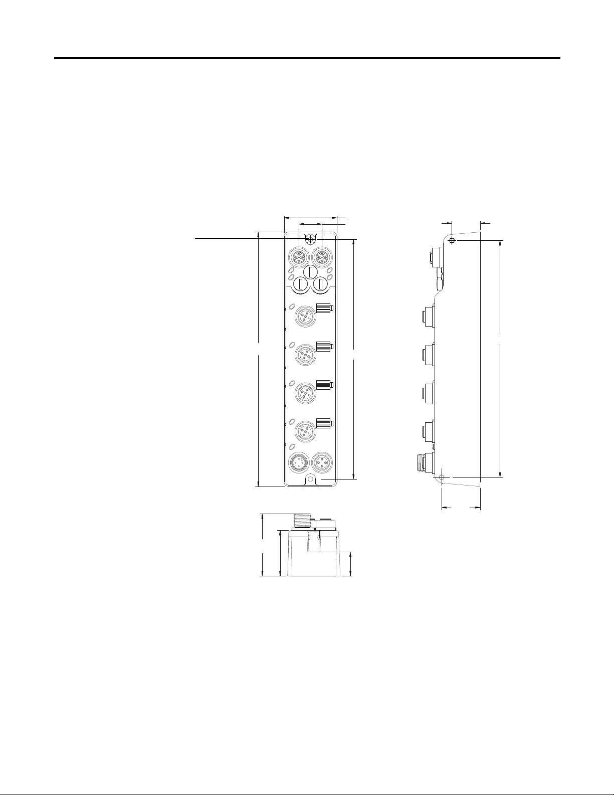
Install Your ArmorBlock Module Chapter 2
37 (1.46)
16.2 (0.64)
168.6 (6.64)
(1.26)
32
(1.70)
43.3
(0.78)
19.8
166.5 (6.56)
27
(1.06)
6LGH0RXQWLQJ
)URQW0RXQWLQJ
179 (7.05)
18
(0.71)
Millimeters
(Inches)
45870
Functional Earth
Grounds the I/O block
EtherNet/IP communication
circuitry which is designed to
mitigate the effect of noise on
the network. It requires a solid
earth ground connection,
either through a metal screw
to a grounded metal panel or
through a wire.
Mount the Module
Two sets of mounting holes are used to mount the module directly to a panel or
machine. Mounting holes accommodate #6 (M3) pan head screws. The torque
specification is 0.68 Nm (6 lb-in.).
To mount the module on a wall or panel, use the screw holes provided in the
module. Refer to the drilling dimensions illustration to guide you in mounting
the module.
Mounting Dimensions
Install the mounting base as follows:
1. Lay out the required points as shown above in the drilling dimension
drawing.
2. Drill the necessary holes for #6 (M3) pan head screws.
Rockwell Automation Publication 1732E-UM005A-EN-E - July 2012 9
3. Mount the module using #6 (M3) screws.
Page 18
Chapter 2 Install Your ArmorBlock Module
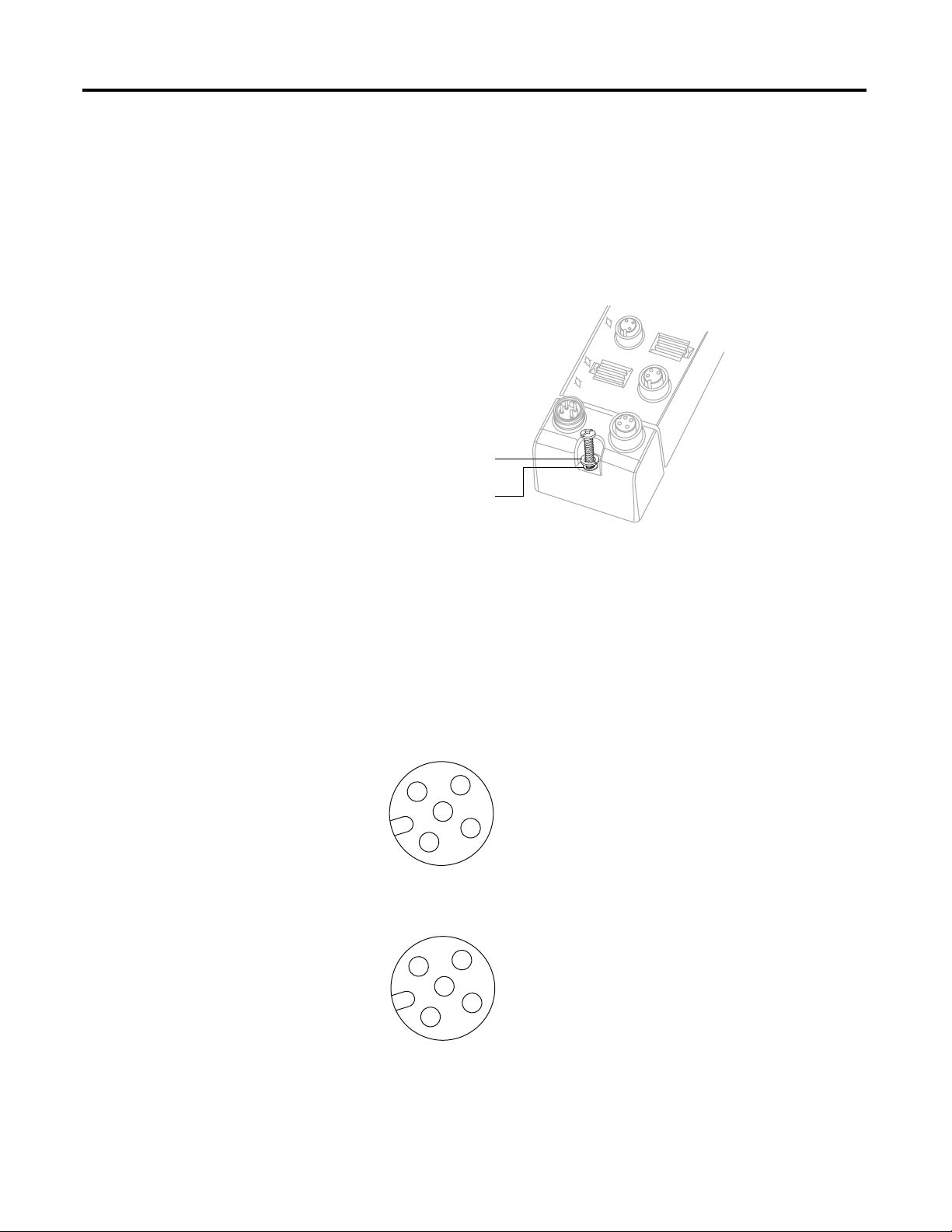
45768
Lock washer
Flat washer
3
4
1
2
5
45868
(View into connector)
Pin 1 Current Input +
Pin 2 Current Common
Pin 3 Voltage Input +
Pin 4 Voltage Common
Pin 5 No Connect
45868
(View into connector)
Pin 1Current Output +
Pin 2Current Common
Pin 3Voltage Output +
Pin 4Voltage Common
Pin 5No Connect
Mount the Module in High Vibration Areas
If you mount the module in an area that is subject to shock or vibration, we
recommend you use a flat and a lock washer to mount the module. Mount the flat
and the lock washer as shown in the mounting illustration. Torque the mounting
screws to 0.68 Nm (6 lb-in.).
High Vibration Area Mounting
Wire the Module
The 1732E-IF4M12R, 1732E-OF4M12R ArmorBlock EtherNet/IP modules
have 5-pin micro-style M12 I/O connectors. We provide caps to cover the unused
connectors on your module. Connect the quick-disconnect cord sets you selected
for your module to the appropriate ports.
I/O Connectors
Micro-style M12 5-Pin Input Female Connector – 1732E-IF4M12R
Micro-style M12 5-Pin Input Female Connector – 1732E-OF4M12R
(1)
3
2
5
4
1
10 Rockwell Automation Publication 1732E-UM005A-EN-E - July 2012
(1) Only 4 of the 5 pins are active. The center pin (5) is internally tied to signal ground to minimize
external noise pickup.
Page 19

Ethernet Connector
IMPORTANT
IMPORTANT
(View into connector 1)
Pin 1M12_Tx+
Pin 2 M12_Rx+
Pin 3 M12_TxPin 4 M12_RxPin 5 Connector shell shield GND
44808
D-Code
M12 Pin
Wire Color Signal 8-way Modular
RJ45 Pin
1White-
orange
TX+ 1
2 White-green RX+ 3
3 Orange TX- 2
4GreenRX-6
1
4
3
2
3
4
1
2
45764
(View into receptacle)
Pin 1 Auxiliary power+
Pin 2 Module power+
Pin 3 Module powerPin 4 Auxiliary power-
45763
Male Input
Female Output
D-Code Micro Network Female Connector
5
1
Install Your ArmorBlock Module Chapter 2
4
2
3
Use the 1585D–M4DC–H: Polyamide small body unshielded mating
connectors for the D-Code M12 female network connector.
Note that the distance between the center of each Ethernet connector
is 16.2 mm (see Mounting Dimensions on page 9
).
Rockwell Automation recommends the use of suitable cable based on
this measurement. Some of the recommended cables are 1585DM4TBJM-x and 1585D-M4TBDM-x for daisychains.
Use two twisted pair CAT5E UTP or STP cables.
Rockwell Automation Publication 1732E-UM005A-EN-E - July 2012 11
Power Connectors
Attach the mini-style 4-pin connector to the mini-style 4-pin receptacle as shown
below.
Micro-style 4-Pin Input Male Receptacle
The power required by the module is based on a 4-pin micro-style connector
system. Power can be daisy chained through the module either left to right or
right to left. The standard configuration is with Module/Auxiliary power
entering the module on the left connector.
Page 20
Chapter 2 Install Your ArmorBlock Module
IMPORTANT
Both modules require two 24V DC (nominal) supplies. These supplies are called
the Module Power and the Auxiliary Power. The Module power supplies the
microprocessor and Ethernet portions of the module. The Auxiliary Power
provides power for the voltage or current outputs on the 1732E-OF4M12R
analog output module.
Internally, the Module Power and Auxiliary Power are electrically isolated.
The maximum current that any pin on the power connectors can
carry is 4 A.
ATTENTION: To comply with the CE Low Voltage Directive (LVD), this
equipment and all connected I/O must be powered from a source
compliant with the following:
Safety Extra Low Voltage (SELV) or Protected Extra Low Voltage (PELV).
ATTENTION: To comply with UL restrictions, this equipment must be
powered from a source compliant with the following: Limited Voltage/
Limited Current.
ATTENTION: The device meets UL Type 1 Enclosure rating.
Chapter Summary
In this chapter, you learned how to install and wire your module. The following
chapter describes how to configure your module to communicate on the
EtherNet/IP network by providing an IP address, gateway address, and Subnet
mask.
12 Rockwell Automation Publication 1732E-UM005A-EN-E - July 2012
Page 21

Chapter
Configure Your Analog Input and Output
Modules with RSLogix 5000 Software
3
Introduction
This chapter guides you through the steps required to configure your modules
using the RSLogix 5000 software. Note that the modules presented in this
chapter can be configured using RSLogix 5000 software, version 20, or later.
Topic Page
Set Up the Hardware 14
Create the Example Application 15
Configure Your I/O Module 16
Overview of the Configuration Process through RSLogix 5000 16
Add a New Bridge and Module to Your RSLogix 5000 Project 16
Download the Program to Your Controller 21
Edit Your 1732E-IF4M12R Configuration 21
Edit Your 1732E-OF4M12R Configuration 30
Status and Monitoring Tabs 41
Chapter Summary 42
Adding the two modules through RSLogix 5000 involve the same general
procedure. Note, however, that the two modules do not have exactly similar
Module Definition properties or configuration parameters. The customization of
both modules are distinctly covered in the next sections.
Rockwell Automation Publication 1732E-UM005A-EN-E - July 2012 13
Page 22
Chapter 3 Configure Your Analog Input and Output Modules with RSLogix 5000 Software
Local
Chassis
1732E
ArmorBlock
Logix5565
Controller (slot 1)
1756-EN2T
192.168.1.20 (slot 3)
Data
Switch
192.168.1.100
Programming
Terminal
0
1732E ArmorBlock
Ethernet Module
192.168.1.3
44971
32Slot 1
Embedded
Technology
Set Up the Hardware
In this example, a ControlLogix chassis contains the Logix5565 processor in slot
1 and a 1756-EN2T bridge module in slot 3. The 1732E ArmorBlock module is
mounted remotely.
Logix5565
EtherNet/IP
Logix5565
1756-EN2T
To work along with this example set up your system as shown.
• Note that in the example application, the Logix5565 controller and
1756-EN2T module (firmware version 2.3 or higher) are assumed to be in
the slots shown.
• Verify the IP addresses for your programming terminal, 1756-EN2T
module and 1732E ArmorBlock Ethernet module.
• Verify that you connected all wiring and cabling properly.
• Be sure you configured your communication driver (for example,
AB_ETH-1 or AB-ETHIP-1) in RSLinx™ software.
14 Rockwell Automation Publication 1732E-UM005A-EN-E - July 2012
Page 23
Configure Your Analog Input and Output Modules with RSLogix5000 Software Chapter 3
Create the Example Application
Perform the following steps to create the example application:
1. From the File menu, select New.
The New Controller dialog opens.
2. Enter an appropriate name for the Controller, for example,
ArmorBlock_IO_Controller.
3. Select the correct version, chassis type, and slot number of the controller,
and the folder where you want to save the RSLogix 5000 software file
(Create In). The Description is optional.
To use redundancy in your system, select the Redundancy Enabled
checkbox.
4. Click OK.
Rockwell Automation Publication 1732E-UM005A-EN-E - July 2012 15
Page 24

Chapter 3 Configure Your Analog Input and Output Modules with RSLogix 5000 Software
IMPORTANT
Configure Your I/O Module
Overview of the Configuration Process through RSLogix 5000
You must configure your module upon installation. The module will not work
until it has been configured with at least the default configuration.
RSLogix 5000 Configuration Software
You must use RSLogix 5000, version 20 or later, to configure your module. You
have the option of accepting default configuration for your module or writing
point-level configuration specific to your application.
Both options are explained in detail, including views of software screens, in this
chapter.
When you use the RSLogix 5000 software to configure a module, you must
perform the following steps:
1. Add the Local EtherNet/IP Bridge (1756-EN2T, 1756-EN2TR, or
1756-EN3TR) to your project’s I/O Configuration.
2. Add the 1732E-IF4M12R or 1732E-OF4M12R module as a child of the
1756-EN2T module.
Add a New Bridge and Module to Your RSLogix 5000 Project
3. Accept the default configuration or change it to specific configuration for
the module.
4. Edit configuration for a module when changes are needed.
After you have started RSLogix 5000 software and created a controller, you must
add a new bridge and a new module to your project. The bridge allows your
module to communicate with the controller.
The wizard allows you to create a new module and write configuration. You can
use default configuration or write specific configuration for your application.
Click Help on the configuration dialogs shown in this section if you
need assistance in selecting and setting the parameters.
16 Rockwell Automation Publication 1732E-UM005A-EN-E - July 2012
Page 25
Configure Your Analog Input and Output Modules with RSLogix5000 Software Chapter 3
If you are not offline, use this
pull-down menu to go offline.
A. Right-click 1756 Backplane.
B. Select New Module.
A. Select the 1756-EN2T
EtherNet/IP Bridge.
B. Click OK.
Add the Local EtherNet/IP Bridge to the I/O Configuration
1. If necessary, go offline.
2. Add the EtherNet/IP Bridge to your RSLogix 5000 project.
3. Expand Communications and select the new module in the Select Module
dialog that appears. Select the 1756-EN2T EtherNet/IP Bridge.
Rockwell Automation Publication 1732E-UM005A-EN-E - July 2012 17
Page 26
Chapter 3 Configure Your Analog Input and Output Modules with RSLogix 5000 Software
A. Name the bridge.
B. Enter the IP address.
C. Select slot 3 for the EtherNet/IP bridge.
D. Make sure the Minor Revision number
matches your module revision number.
E. Choose an Electronic Keying method.
For more information, see page 23
.
F. Click OK.
4. The New Module dialog opens.
Configure the bridge module as illustrated below.
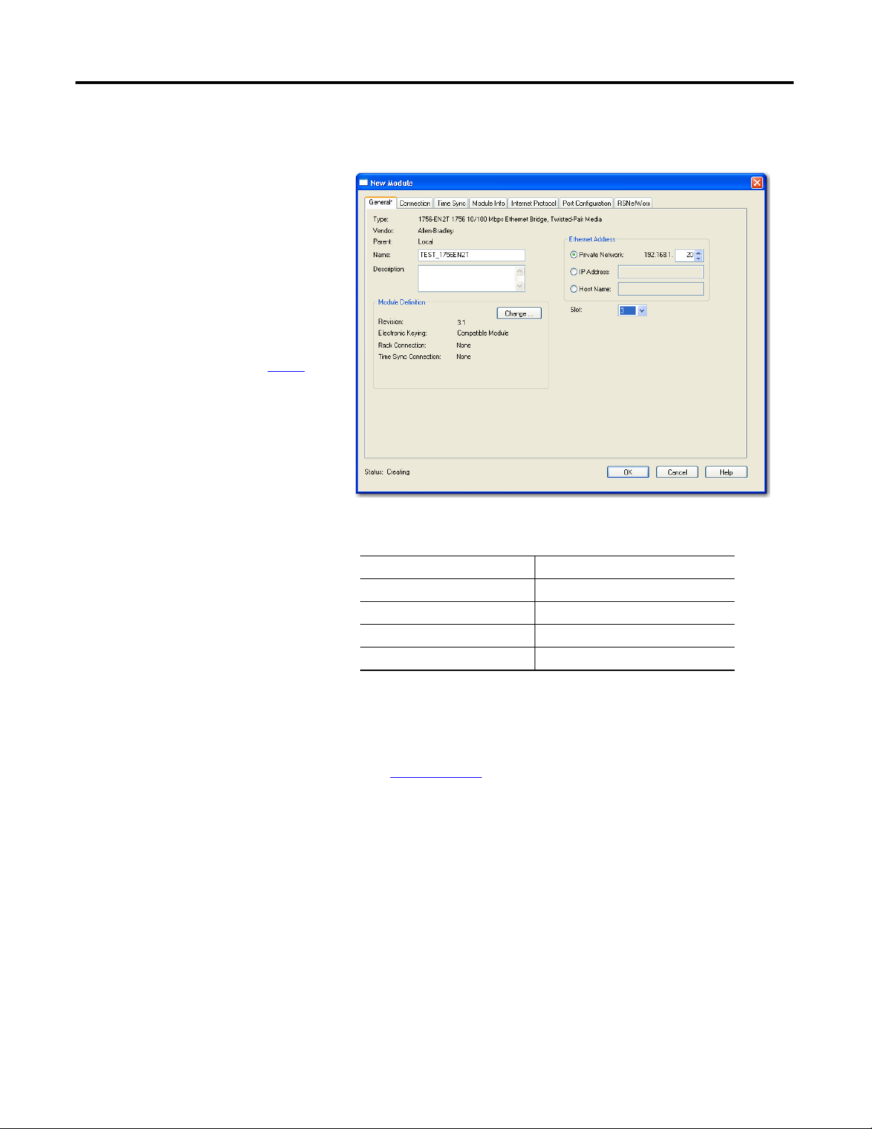
Note that we have entered the following properties in this example:
Name TEST_1756EN2T
IP address 192.168.1.20
Slot 3
Revision 3.1
Electronic Keying Compatible Module
The local 1756-EN2T communication module will communicate with the
1732E ArmorBlock module on Ethernet. Before you can communicate with your
module, you need to add it as a child of the 1756-EN2T communication module.
For more information about using 1756 controller and EtherNet/IP products, see
publication ENET-UM001
.
Add the I/O module as a child of the 1756-EN2T module
1. Right-click the Ethernet folder that appears below the 1756-EN2T bridge
you added to the I/O Configuration tree and select New Module.
18 Rockwell Automation Publication 1732E-UM005A-EN-E - July 2012
Page 27
Configure Your Analog Input and Output Modules with RSLogix5000 Software Chapter 3
TIP
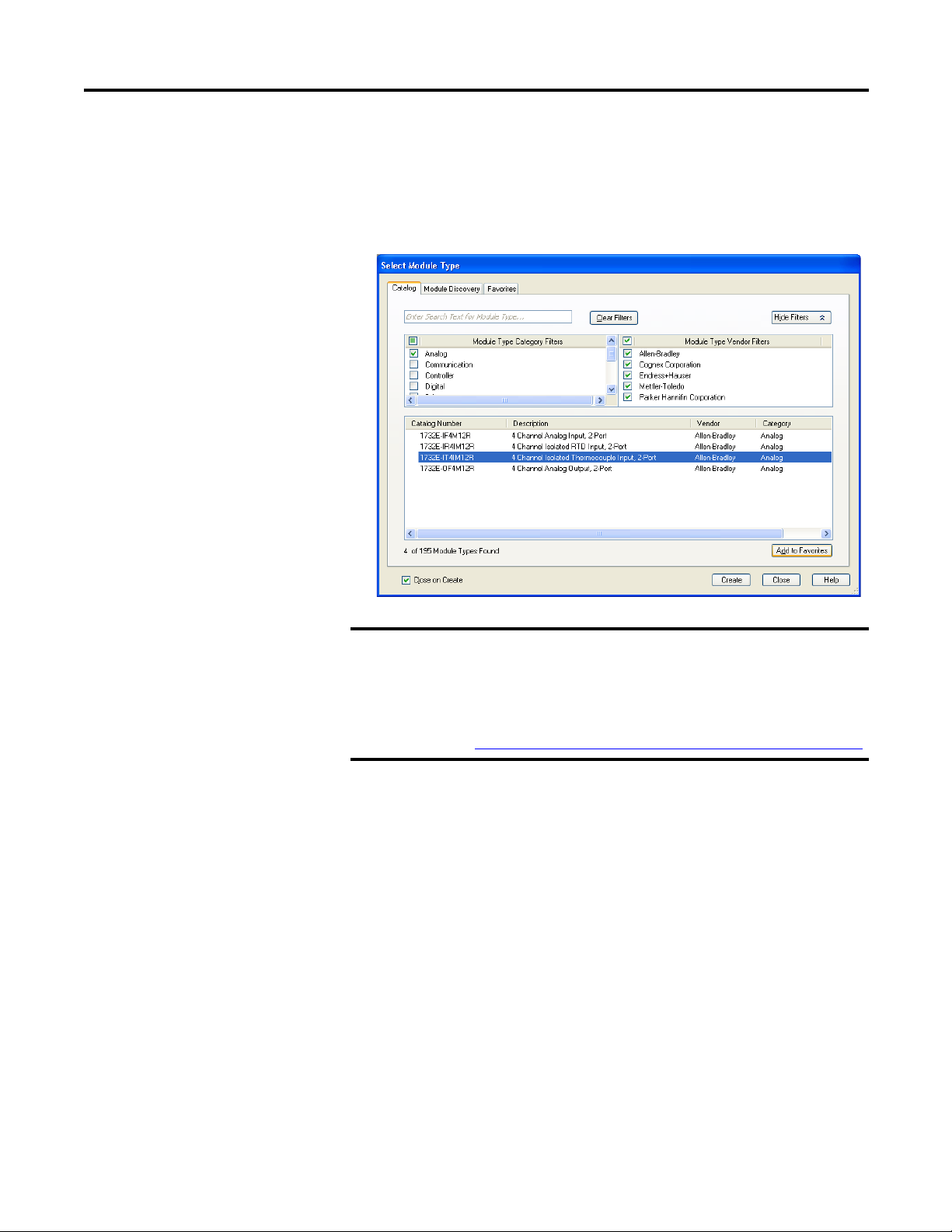
2. On the Select Module Type dialog that appears, select the
1732E-IF4M12R module. Click Create.
To look for the 1732E-IF4M12R module in the list, you can type the
catalog number in the search box or use the filters. To do so, click Clear
Filters and check Analog in the Module Type Category Filters.
If the 1732E-IF4M12R, 1732E-OF4M12R modules are not listed
under the analog category of the Select Module Type dialog,
you may need to download the Add-On Profile (AOP) for the
1732E ArmorBlock 2-Port and install it as an add-on to
RSLogix 5000. The AOP file can be downloaded from:
support.rockwellautomation.com/controlflash/LogixProfiler.asp
Rockwell Automation Publication 1732E-UM005A-EN-E - July 2012 19
Page 28
Chapter 3 Configure Your Analog Input and Output Modules with RSLogix 5000 Software
3. The New Module dialog appears.
Fill in the Module Properties information as shown, and then click OK.
Note that we have used the following properties in this example:
Field Name Value
Name TEST_1732EIF4M12R
IP address 192.168.1.3
Electronic keying Compatible Module
Revision 1.1
Connection Input Only
(This parameter is Exclusive Owner for
1732E-OF4M12R)
To add the 1732E-OF4M12R Analog output module, follow the same
steps. After adding the modules to your project, the I/O Configuration
tree should appear as follows:
This example uses default Module Definition and configuration
properties. To customize your module configuration, go to:
• Edit Your 1732E-IF4M12R Configuration
on page 21
• Edit Your 1732E-OF4M12R Configuration on page 30
20 Rockwell Automation Publication 1732E-UM005A-EN-E - July 2012
Page 29
Configure Your Analog Input and Output Modules with RSLogix5000 Software Chapter 3
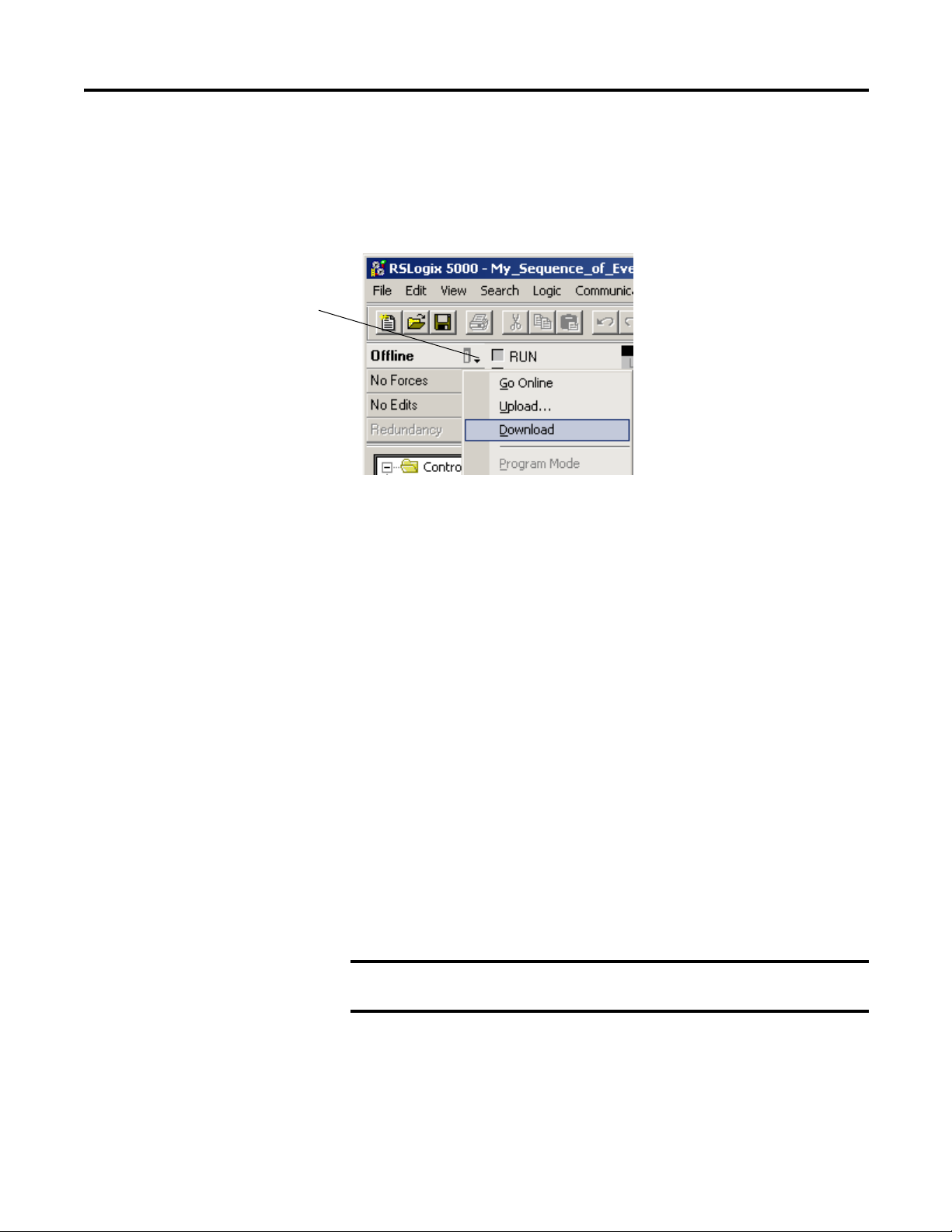
A. Click here to see the
pull-down menu.
B. Click download.
IMPORTANT
Download the Program to Your Controller
After you write configuration for your module, the module does not use this
configuration until you download it to the owner-controller. The download
transfers the entire program to the controller, overwriting any existing program.
Download module configuration as shown below:
Depending on your application, a variety of RSLogix 5000 software screens may
appear to choose a path to your ControlLogix controller and to verify the
download. Navigate those screens as best fits your application.
This completes the download process.
Edit Your 1732E-IF4M12R Configuration
RSLogix 5000 programming software automatically creates module-defined data
types and tags when a module is created. This section describes how to modify
the default configuration for input modules.
Data types symbolically name module configuration, input and output data. Tags
let you provide each a unique name, such as where the user-defined data type and
slot reside on the controller. This information is used to communicate data
between the controller and module.
After you have set configuration for a module, you can review and change your
choices. You can change configuration data and download it to the controller
while online. This is called dynamic reconfiguration.
Your freedom to change some configurable features, though, depends on whether
the controller is in Remote Run Mode or Program Mode.
Although you can change configuration while online, you must
go offline to add or delete modules from the project.
The editing process begins on the main page of RSLogix 5000 software.
Rockwell Automation Publication 1732E-UM005A-EN-E - July 2012 21
Page 30

Chapter 3 Configure Your Analog Input and Output Modules with RSLogix 5000 Software
TIP
1. On the I/O Configuration tree for your project in RSLogix 5000,
right-click the name of your module.
2. Select Properties. The Module Properties dialog appears and has the
following tabs available for configuration.
3. Click any of the tabs to edit the parameters for your module.
The next sections show you how to edit the different tabs in the Module
Properties dialog.
Tabs can be selected in any order. The following examples are for
instructional purposes.
General Tab
The General tab allows you to edit general properties such as Name, IP Address,
and Description for your module.
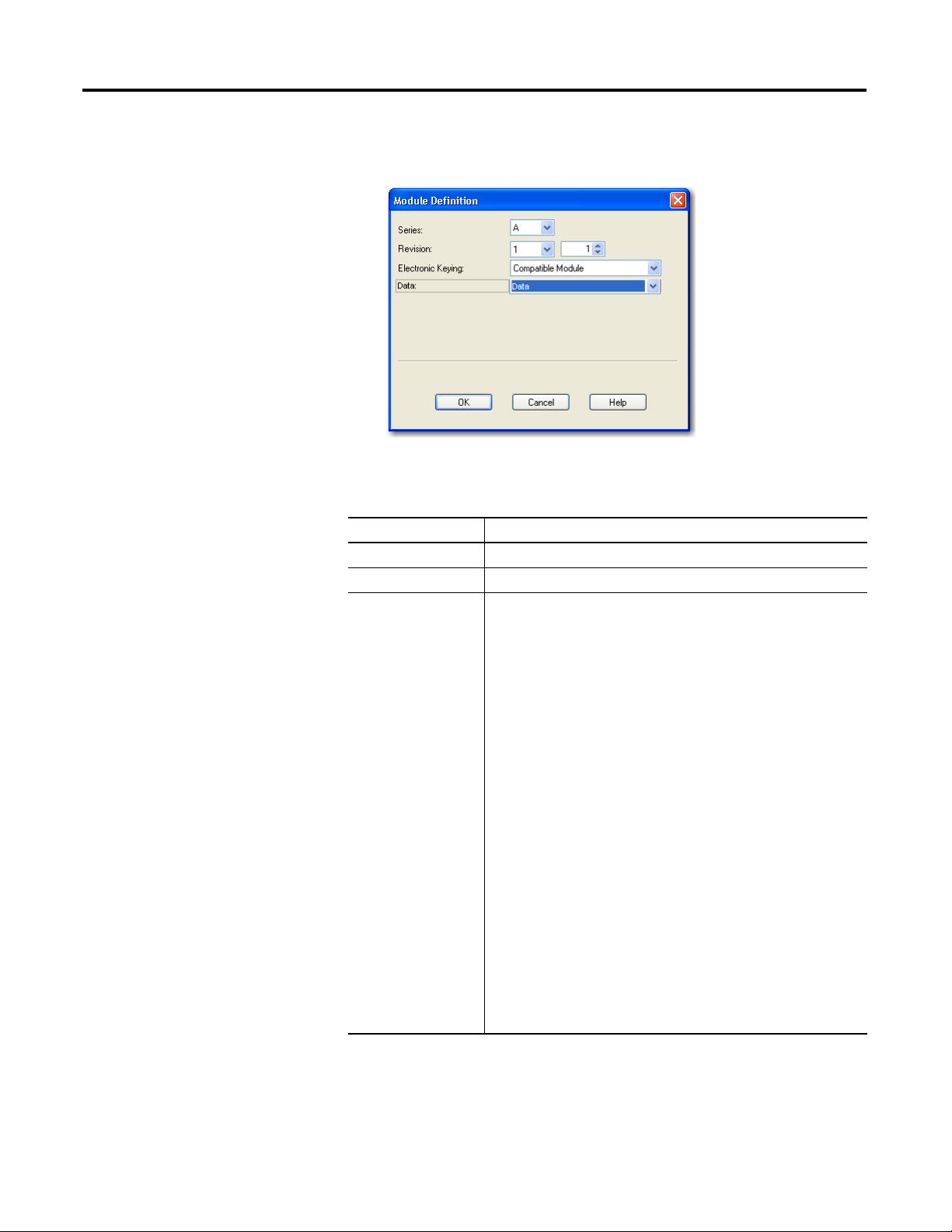
You also can edit Module Definition properties such as revision, electronic
keying, and data. To do so, click Change.
22 Rockwell Automation Publication 1732E-UM005A-EN-E - July 2012
Page 31

Configure Your Analog Input and Output Modules with RSLogix5000 Software Chapter 3
Module Definition Fields
Field Name Description
Series Specifies the module series.
Revision Specifies the module’s major and minor revision.
Electronic Keying The electronic keying feature automatically compares the expected
Connection Available options are Data, Input Only, Exclusive Owner, and Listen Only.
module, as shown in the RSLogix 5000 I/O Configuration tree, to the
physical module before I/O communication begins. You can use electronic
keying to help prevent communication to a module that does not match
the type and revision expected.
For each module in the I/O Configuration tree, the user-selected keying
option determines if, and how, an electronic keying check is performed.
Typically, three keying options are available:
• Exact Match
• Compatible Module (default value)
• Disable Keying
Exact Match is an electronic keying protection mode that requires the
physical module and the module configured in the software to match
according to vendor, catalog number, major revision and minor revision.
Compatible Module indicates that the module determines whether to
accept or reject communication. Compatible Keying is the default setting.
It allows the physical module to accept the key of the module configured
in the software, provided that the configured module is one the physical
module is capable of emulating. The exact level of emulation required is
product and revision specific.
Disable Keying indicates the keying attributes are not considered when
attempting to communicate with a module. Other attributes, such as data
size and format, are considered and must be acceptable before I/O
communication is established. With Disabled Keying, I/O communication
may occur with a module other than the type specified in the I/O
configuration tree with unpredictable results. We generally do not
recommend using Disabled Keying.
Calibration and Configuration options are not available for Listen Only
option.
Input Only specifies an independent connection where a device receives
inputs from the target device and sends configuration data to the target
device. An Input Only connection does not send outputs; it only receives
inputs. You can specify multiple Input Only connections to the target
device from different originators.
Exclusive Owner specifies an independent connection where a single
device controls the output states in the target device. If you have an
existing Exclusive Owner connection to a target device, you cannot
specify another Exclusive Owner or Redundant connection to that same
target device.
Listen Only specifies a dependent connection where a device receives
inputs from the target device, but does not send configuration data with
the target device. A Listen Only connection only functions properly when
another non-Listen Only connection exists to the same target device. A
Listen Only connection does not send outputs; it only receives inputs. You
can specify multiple Listen Only connections to the target device from
different originators.
Connection Tab
The Connection tab on the Module Properties dialog box lets you enter a
requested packet interval (RPI), inhibit a module, and set a connection fault
Rockwell Automation Publication 1732E-UM005A-EN-E - July 2012 23
Page 32

Chapter 3 Configure Your Analog Input and Output Modules with RSLogix 5000 Software
when the controller is in Run mode. The RPI provides a defined, maximum
period of time when data is transferred to the owner-controller.
1. Choose from the options on the Connection tab.
Connection Tab Fields
Field Description
Requested Packet Interval
(RPI) (ms)
Inhibit Module Check the box to prevent communication between the ownercontroller
Major fault On Controller If
Connection Fails While in
Run Mode
Use Unicast Connection
over EtherNet/IP
Module Fault The fault box is empty if you are offline. The type of connection fault
A user-defined rate at which the module updates the information sent
to its owner-controller.
This interval defines the slowest rate at which a module sends its
data to the owner-controller. The time ranges from 2.0…750 ms and
is sent to the module with all other configuration parameters.
and the module. This option allows for maintenance of the module
without faults being reported to the controller.
Check the box to create a major fault if there is a connection failure
with the controller while in Run mode.
This option is enabled by default.
Unicast connections are point to point transmissions between a
source node and destination node on the network. A Frame is sent to
a single destination.
appears in the text box if a fault occurs when the module is online.
2. Do one of the following:
• Click Apply to store a change but stay on the dialog box to choose
another tab.
• Click OK if you are finished making changes.
24 Rockwell Automation Publication 1732E-UM005A-EN-E - July 2012
Page 33

Configure Your Analog Input and Output Modules with RSLogix5000 Software Chapter 3
Configuration Tab
The Configuration tab on the Module Properties dialog box lets you program
information on each of the four channels on the 1732E-IF4M12R module.
1. Choose from the options on the Configuration tab.
Configuration tab
Field Description
Channel Indicates the four input channels 0…3.
Input range Input can be voltage or current, with current mode as default.
Digital filter Serves to reject higher frequency noise and harmonics.
It has the following input range options:
Choose a value in milliseconds that specifies the time constant for a digital
first order lowpass filter on the input. A value of 0 disables the filter.
Rockwell Automation Publication 1732E-UM005A-EN-E - July 2012 25
Page 34

Chapter 3 Configure Your Analog Input and Output Modules with RSLogix 5000 Software
Data =
(Signal-LowSignal)(HighEngineering-LowEngineering)
High Signal - Low Signal
+ Low Engineering
Data =
(Signal-LowSignal)(HighEngineering-LowEngineering)
High Signal - Low Signal
+ Low Engineering
Configuration tab
Field Description
High Engineering High engineering value helps determine the engineering units the signal
values scale into. The high engineering term corresponds to the high signal
value. The scaling equation used is shown below.
Low Engineering One of four points used in scaling. The low engineering helps determine the
Real Time Sample
(RTS)
engineering units the signal values scale into. The low engineering term
corresponds to the low signal value. The scaling equation used is as follows:
This parameter instructs the module how often to scan its input channels
and obtain all available data. This feature is applied on a module-wide
basis.
2. Do one of the following:
• Click Apply to store a change but stay on the dialog box to choose
another tab.
• Click OK if you are finished making changes.
Alarm Configuration Tab
The Alarm Configuration tab on the Module Properties dialog box lets you
program high and low limits, and disable and latch alarms per channel.
26 Rockwell Automation Publication 1732E-UM005A-EN-E - July 2012
Page 35

Configure Your Analog Input and Output Modules with RSLogix5000 Software Chapter 3
Click Channel button to set limits
and alarm configuration for each
of the 4 channels.
Use the sliders to set limits. HH
slider sets High High limits; HI
sets High limits; LL for Low Low;
and LO for Low.
1. Choose from the options on the Alarm Configuration tab.
Alarm Configuration tab
Field What to do Description
Channel Select a push button
to correspond to a
channel (0…3)
Process Alarms Type a value for each of the four alarm trigger
High High Choose from
-32,768...32,767
High Choose from
-32,768...32,767
Low Choose from
-32,768...32,767
Click the channel that is being configured.
points that alert you when the module has
exceeded these limitations.
You also can use the respective slider icon to set a
trigger value.
The Unlatch buttons are enabled only when the
module is online.
See Process Alarms
information.
Select a value so that any value out of range in this
field causes a profile validation error. This value
also appears in the HH slider on
this dialog.
Select a value so that any value out of range in this
field causes a profile validation error. This value
also appears in the HI slider on this dialog.
Select a value so that any value out of range in this
field causes a profile validation error. This value
also appears in the LO slider on this dialog.
on page 46 for more
Rockwell Automation Publication 1732E-UM005A-EN-E - July 2012 27
Page 36

Chapter 3 Configure Your Analog Input and Output Modules with RSLogix 5000 Software
Alarm Configuration tab
Field What to do Description
Low Low Choose from
-32,768...32,767
Disable All Alarms Click to check the
checkbox
Latch Process Alarms Click to check the
checkbox
2. After the channels are configured, do one of the following:
• Click Apply to store a change but stay on the dialog box to choose
another tab.
• Click OK to apply the change and close the dialog box.
• Click Cancel to close the dialog box without applying changes.
Select a value so that any value out of range in this
field causes a profile validation error. This value
also appears in the LL slider on this dialog.
Check the box to disable all alarms.
Important: When you disable all alarms, you
disable process, and channel diagnostic alarms (for
example, underrange and overrange). We
recommend that you disable only unused channels
so extraneous alarm bits are not set.
Check the box to latch an alarm in the set position
even if the condition that causes the alarm
disappears.
Click to unlatch all alarms together. This feature is
disabled when offline
Internet Protocol Tab
1. To configure your IP settings, click the Internet Protocol tab. This tab is
only available for editing when the device is online. To manually configure
your IP settings, specify the IP address in the Physical Module IP Address
field.
28 Rockwell Automation Publication 1732E-UM005A-EN-E - July 2012
Page 37

Configure Your Analog Input and Output Modules with RSLogix5000 Software Chapter 3
IMPORTANT
2. On other fields (Domain Name, Host Name, Primary DNS Server
Address, Secondary DNS Server Address), specify the corresponding
parameter. Click Set and then click OK.
Port Configuration Tab
To configure the Ethernet ports, click the Port Configuration tab.
This tab is only available for editing when the device is online.
To configure the ports:
To Then
Use the default port speed and duplex settings Leave Auto-negotiate port speed and duplex
Manually configure your port’s speed and
duplex settings
Consider the following when you configure the module’s port settings:
• If the module is connected to an unmanaged switch, leave Auto-negotiate port
speed and duplex checked or the module will fail.
• If you are forcing the port speed and duplex with a managed switch, the
corresponding port of the managed switch must be forced to the same settings or
the module will fail.
checked. This setting determines the actual speed
and duplex setting.
Follow these steps.
1. Clear the Auto-negotiate port speed and duplex
checkbox.
2. From the Current Port Speed pull-down menu,
choose a port speed.
3. From the Current Duplex pull-down menu,
choose the appropriate Duplex value, that is,
Half Duplex or Full Duplex.
Rockwell Automation Publication 1732E-UM005A-EN-E - July 2012 29
Page 38

Chapter 3 Configure Your Analog Input and Output Modules with RSLogix 5000 Software
IMPORTANT
Calibration Tab
The Calibration tab on the Module Properties dialog box lets you recalibrate the
module, if necessary. Calibration corrects any hardware inaccuracies on a
particular channel.
For detailed information about calibration, see Calibrate Your Modules on
page 45.
Edit Your 1732E-OF4M12R Configuration
30 Rockwell Automation Publication 1732E-UM005A-EN-E - July 2012
RSLogix 5000 programming software automatically creates module-defined data
types and tags when a module is created. This section describes how to modify
the default configuration for input modules.
Data types symbolically name module configuration, input and output data. Tags
let you provide each a unique name, such as where the user-defined data type and
slot reside on the controller. This information is used to communicate data
between the controller and module.
After you have set configuration for a module, you can review and change your
choices. You can change configuration data and download it to the controller
while online. This is called dynamic reconfiguration.
Your freedom to change some configurable features, though, depends on whether
the controller is in Remote Run Mode or Program Mode.
Although you can change configuration while online, you must
go offline to add or delete modules from the project.
Page 39

Configure Your Analog Input and Output Modules with RSLogix5000 Software Chapter 3
TIP
The editing process begins on the main page of RSLogix 5000 software.
1. On the I/O Configuration tree for your project in RSLogix 5000,
right-click the name of your module.
2. Select Properties. The Module Properties dialog appears and has the
following tabs available for configuration.
3. Click any of the tabs to edit the parameters for your module.
The next sections show you how to edit the different tabs in the Module
Properties dialog.
Tabs can be selected in any order. The following examples are for
instructional purposes.
General Tab
The General tab allows you to edit general properties such as Name, IP Address,
and Description for your module.
Rockwell Automation Publication 1732E-UM005A-EN-E - July 2012 31
Page 40
Chapter 3 Configure Your Analog Input and Output Modules with RSLogix 5000 Software
You also can edit Module Definition properties such as revision, electronic
keying, and data. To do so, click Change.
General Tab Field Description
Field Name Description
Series Specifies the module series.
Revision Specifies the module’s major and minor revision.
Electronic Keying The electronic keying feature automatically compares the expected
module, as shown in the RSLogix 5000 I/O Configuration tree, to the
physical module before I/O communication begins. You can use electronic
keying to help prevent communication to a module that does not match
the type and revision expected.
For each module in the I/O Configuration tree, the user-selected keying
option determines if, and how, an electronic keying check is performed.
Typically, three keying options are available:
• Exact Match
• Compatible Module (default value)
• Disable Keying
Exact Match is an electronic keying protection mode that requires the
physical module and the module configured in the software to match
according to vendor, catalog number, major revision and minor revision.
Compatible Module indicates that the module determines whether to
accept or reject communication. Compatible Keying is the default setting.
It allows the physical module to accept the key of the module configured
in the software, provided that the configured module is one the physical
module is capable of emulating. The exact level of emulation required is
product and revision specific.
Disable Keying indicates the keying attributes are not considered when
attempting to communicate with a module. Other attributes, such as data
size and format, are considered and must be acceptable before I/O
communication is established. With Disabled Keying, I/O communication
may occur with a module other than the type specified in the I/O
configuration tree with unpredictable results. We generally do not
recommend using Disabled Keying.
32 Rockwell Automation Publication 1732E-UM005A-EN-E - July 2012
Page 41

Configure Your Analog Input and Output Modules with RSLogix5000 Software Chapter 3
General Tab Field Description
Field Name Description
Connection Available options are Data and Listen Only, with Data as default.
Calibration and Configuration options are not available for Listen Only
option.
Listen Only specifies a dependent connection where a device receives
inputs from the target device, but does not send configuration data with
the target device. A Listen Only connection only functions properly when
another non-Listen Only connection exists to the same target device. A
Listen Only connection does not send outputs; it only receives inputs. You
can specify multiple Listen Only connections to the target device from
different originators.
Connection Tab
The Connection tab on the Module Properties dialog box lets you enter a
requested packet interval (RPI), inhibit a module, and set a connection fault
when the controller is in Run mode. The RPI provides a defined, maximum
period of time when data is transferred to the owner-controller.
1. Choose from the options on the Connection tab.
Connection Tab Fields
Field Description
Requested Packet Interval
(RPI) (ms)
Inhibit Module Check the box to prevent communication between the ownercontroller
Major fault On Controller If
Connection Fails While in
Run Mode
Use Unicast Connection
over EtherNet/IP
Module Fault The fault box is empty if you are offline. The type of connection fault
A user-defined rate at which the module updates the information sent
to its owner-controller.
This interval defines the slowest rate at which a module sends its
data to the owner-controller. The time ranges from 2.0…750 ms and
is sent to the module with all other configuration parameters.
and the module. This option allows for maintenance of the module
without faults being reported to the controller.
Check the box to create a major fault if there is a connection failure
with the controller while in Run mode.
This option is enabled by default.
Unicast connections are point to point transmissions between a
source node and destination node on the network. A Frame is sent to
a single destination.
appears in the text box if a fault occurs when the module is online.
Rockwell Automation Publication 1732E-UM005A-EN-E - July 2012 33
Page 42

Chapter 3 Configure Your Analog Input and Output Modules with RSLogix 5000 Software
2. Do one of the following:
• Click Apply to store a change but stay on the dialog box to choose
another tab.
• Click OK if you are finished making changes.
34 Rockwell Automation Publication 1732E-UM005A-EN-E - July 2012
Page 43

Configure Your Analog Input and Output Modules with RSLogix5000 Software Chapter 3
Configuration Tab
1. Choose from the options on the Configuration tab.
Configuration tab
Field Description
Channel Indicates the four input channels 0…3.
Output range Sets the output as current or voltage output, with the following output range
options:
Rockwell Automation Publication 1732E-UM005A-EN-E - July 2012 35
Page 44

Chapter 3 Configure Your Analog Input and Output Modules with RSLogix 5000 Software
Data =
(Signal-LowSignal)(HighEngineering-LowEngineering)
High Signal - Low Signal
+ Low Engineering
Data =
(Signal-LowSignal)(HighEngineering-LowEngineering)
High Signal - Low Signal
+ Low Engineering
Click Channel button to set limits
and alarm configuration for each
of the 4 channels.
Use the sliders to set limits. HI
sets High limits; and LO for Low.
Configuration tab
Field Description
High Engineering High engineering value helps determine the engineering units the signal
values scale into. The high engineering term corresponds to the high signal
value. The scaling equation used is shown below.
Low Engineering Low engineering helps determine the engineering units the signal values
scale into. The low engineering term corresponds to the low signal value.
The scaling equation used is as follows:
Limits Configuration Tab
The Limits Configuration tab on the Module Properties dialog box lets you
program high and low limits, and disable and latch alarms per channel.
36 Rockwell Automation Publication 1732E-UM005A-EN-E - July 2012
Page 45

Configure Your Analog Input and Output Modules with RSLogix5000 Software Chapter 3
1. Choose from the options on the Limit Configuration tab.
Limit Configuration tab
Field What to do Description
Channel Select apush button
Clamp Limits
High Clamp
Low Clamp
Disable All Alarms Click to check the
Latch Limit Alarms Click to check the
to correspond to a
channel (0…3).
Type a high and low
clamp value that
limits the output
from the analog
module within this
range.
checkbox
checkbox
Refers to the channel being configured.
Click to configure.
See Clamping/Limiting
information.
Check the box to disable all alarms.
Important: When you disable all alarms, you
disable process, and channel diagnostic alarms (for
example, underrange and overrange). We
recommend that you disable only unused channels
so extraneous alarm bits are not set.
Check the box to latch an alarm if the controller
data value exceeds the clamping limit.
on page 47 for more
2. After the channels are configured, do one of the following:
• Click Apply to store a change but stay on the dialog box to choose
another tab.
• Click OK to apply the change and close the dialog box.
• Click Cancel to close the dialog box without applying changes.
Rockwell Automation Publication 1732E-UM005A-EN-E - July 2012 37
Page 46

Chapter 3 Configure Your Analog Input and Output Modules with RSLogix 5000 Software
Fault/Program Action Tab
1. To configure the Fault/Program Action tab, set the following parameters:
Fault/Program Action tab
Field What to do Description
Channel Select a push button to
correspond to a channel
(0…3).
Fault Mode Select from a dropdown
list:
Fault Value Specify a value. Activates when Use Fault Value is selected as Fault
Program Mode Select from a dropdown
list:
Refers to the channel being configured.
Allows the user to select any of the following
output behavior for each channel when in Fault
mode:
• Go to Low Clamp (default)
• Hold Last State
• Go to High Clamp
• Use Fault Value
Mode. The user needs to enter a value for the
output to transition to when there is a
communication fault.
Allows the user to select any of the following
output behavior for each channel when in Program
mode:
• Go to Low Clamp (default)
• Hold Last State
• Go to High Clamp
• Use Program Value
Program Value Specify a value. Activates when Use Program Value is selected as
38 Rockwell Automation Publication 1732E-UM005A-EN-E - July 2012
Program Mode. The user needs to enter a value for
the output to transition to when in Program mode.
Page 47

Configure Your Analog Input and Output Modules with RSLogix5000 Software Chapter 3
2. Do one of the following:
• Click Apply to store a change but stay on the dialog box to choose
another tab.
• Click OK if you are finished making changes.
Internet Protocol Tab
1. To configure your IP settings, click the Internet Protocol tab. This tab is
only available for editing when the device is online. To manually configure
your IP settings, specify the IP address in the Physical Module IP Address
field.
2. On the other fields (Domain Name, Host Name, Primary DNS Server
Address, Secondary DNS Server Address), specify the corresponding
parameter. Click Set and then click OK.
Rockwell Automation Publication 1732E-UM005A-EN-E - July 2012 39
Page 48

Chapter 3 Configure Your Analog Input and Output Modules with RSLogix 5000 Software
IMPORTANT
Port Configuration Tab
To configure the Ethernet ports, click the Port Configuration tab.
This tab is only available for editing when the device is online.
To configure the ports:
To Then
Use the default port speed and duplex settings Leave Auto-negotiate port speed and duplex
Manually configure your port’s speed and
duplex settings
Consider the following when you configure the module’s port settings:
• If the module is connected to an unmanaged switch, leave Auto-negotiate port
speed and duplex checked or the module will fail.
• If you are forcing the port speed and duplex with a managed switch, the
corresponding port of the managed switch must be forced to the same settings
or the module will fail.
checked. This setting determines the actual speed
and duplex setting.
Follow these steps.
1. Clear the Auto-negotiate port speed and duplex
checkbox.
2. From the Current Port Speed pull-down menu,
choose a port speed.
3. From the Current Duplex pull-down menu,
choose the appropriate Duplex value, that is,
Half Duplex or Full Duplex.
Calibration Tab
The Calibration tab on the Module Properties dialog box lets you recalibrate the
module, if necessary. Calibration corrects any hardware inaccuracies on a
40 Rockwell Automation Publication 1732E-UM005A-EN-E - July 2012
Page 49

Configure Your Analog Input and Output Modules with RSLogix5000 Software Chapter 3
particular channel. The Calibration Range that appears on the Calibration tab is
dependent on the output range configured for the channel.
For detailed information about calibration, see Calibrate Your Modules on
page 45.
Status and Monitoring Tabs
Although each dialog box maintains importance during online monitoring, some
of the tabs, such as the Module Info and Network, are blank during the initial
module configuration.
Rockwell Automation Publication 1732E-UM005A-EN-E - July 2012 41
Page 50

Chapter 3 Configure Your Analog Input and Output Modules with RSLogix 5000 Software
Check the status of your module using these tabs.
Chapter Summary
42 Rockwell Automation Publication 1732E-UM005A-EN-E - July 2012
This chapter provided instructions on how to configure the 1732E ArmorBlock
Analog Input and Output modules through the RSLogix 5000 software.
Page 51

Chapter
4
Configurable Features for the Analog Input
and Output Modules
Overview
Configurable Features for the 1732E-IF4M12R Input Module
This chapter describes how the different configuration parameters affect the
analog input and output channels. It also includes the data structure for both
modules.
Topic Page
Configurable Features for the 1732E-IF4M12R Input Module 43
Configurable Features for the 1732E-OF4M12R Output Module 46
Data Tables 48
Chapter Summary 52
The parameters discussed in this chapter can be configured through the
RSLogix 5000 software. See the previous chapter, Configure Your Analog Input
and Output Modules with RSLogix 5000 Software, to learn more about the stepby-step I/O configuration and setup process using RSLogix 5000.
The following features can be configured on each of the four channels for the
1732E-IF4M12R module, unless otherwise specified.
Feature Page
Input Types and Ranges 44
Digital Filters 44
High Engineering/Low Engineering 45
Real-time Sampling 46
Process Alarms 46
Rockwell Automation Publication 1732E-UM005A-EN-E - July 2012 43
Page 52

Chapter 4 Configurable Features for the Analog Input and Output Modules
Yn = Yn-1 +
[Δt]
Δt + TA
(X
n
- Yn - 1)
Input Types and Ranges
Each of the four 1732E-IF4M12R input points can be configured as either
current input or voltage input, with current mode as default configuration.
The user must do two things to use the input as a current or voltage device:
• Wire for the correct input type (see page 10
• Configure accordingly through RSLogix 5000 (see page 25
)
)
Current Mode
In current mode, the module supports either 0…20 mA or 4…20 mA input
currents independently for each channel, with the latter as default input range.
Voltage Mode
In voltage mode, the module supports both unipolar ranges of 0…10V and 0…5V,
and bipolar ranges of ±5V and ±10V. The nominal common mode input
impedance per channel in voltage mode is 125 kΩ.
Digital Filters
The digital filter smooths input data noise transients for all channels on the
module. This feature is applied on a per channel basis. The digital filter value
specifies the time constant for a digital first order lowpass filter on the input. It is
specified in units of milliseconds. A value of 0 disables the filter.
The digital filter equation is a classic first order lag equation.
Yn = Present output, filtered peak voltage (PV)
Yn-1 =Previous output, filtered PV
Δt = Module channel update time (seconds)
TA = Digital filter time constant (seconds)
Xn = Present input, unfiltered PV
44 Rockwell Automation Publication 1732E-UM005A-EN-E - July 2012
Page 53

Configurable Features for the Analog Input and Output Modules Chapter 4
0 0.01 0.5 0.99 Time in Seconds
16723
100%
63%
0
Amplitude
Unfiltered Input
TA = 0.01 sec
TA = 0.5 sec
TA = 0.99 sec
Data =
(Signal-LowSignal)(HighEngineering-LowEngineering)
High Signal - Low Signal
+ Low Engineering
Using a step input change to illustrate the filter response, as shown in the
illustration, you can see that when the digital filter time constant elapses, 63.2%
of the total response is reached. Each additional time constant achieves 63.2% of
the remaining response.
To set digital filters in RSLogix 5000, go to page 25
.
High Engineering/Low Engineering
High engineering and low engineering values help determine the engineering
units the signal values scale into. The high engineering term corresponds to the
high signal value, while the low engineering term corresponds to the low signal
value. The scaling equation used is shown below.
Rockwell Automation Publication 1732E-UM005A-EN-E - July 2012 45
Page 54

Chapter 4 Configurable Features for the Analog Input and Output Modules
Real-time Sampling
This parameter instructs the module how often to scan its input channels and
obtain all available data. The data is produced at the rate configured by the RPI
parameter on the connection tab. This feature is applied on a module-wide basis.
Process Alarms
Configurable Features for the 1732E-OF4M12R Output Module
Process alarms alert you when the module has exceeded configured high or low
limits for each channel. You can latch process alarms. These are set at four user
configurable alarm trigger points.
• High high
• High
• Low
• Low low
To set process alarms via RSLogix 5000, go to page 26
The following features can be configured on each of the four channels for the
1732E-OF4M12R module, unless otherwise specified.
Feature Page
Output Types and Ranges 46
High Engineering/Low Engineering 47
Fault Mode and Program Mode 47
Clamping/Limiting 47
.
Output Types and Ranges
Each of the four 1732E-OF4M12R output points can be configured as either
current output or voltage output, with current mode as default configuration.
46 Rockwell Automation Publication 1732E-UM005A-EN-E - July 2012
Page 55

Configurable Features for the Analog Input and Output Modules Chapter 4
The user must do two things to use the output as a current or voltage device:
• Wire for the correct output type (see page 10
• Configure accordingly through RSLogix 5000 (see page 35
)
)
Current Mode
In current mode, the module supports either 0…20 mA or 4…20 mA output
currents independently for each channel, with the latter as default output range.
Voltage Mode
In voltage mode, the module supports ranges of 0…5V, -5…+5V, 0…10V, or 10…+10V, independently for each channel.
In voltage mode, the outputs are short circuit protected to 20 mA per channel.
High Engineering/Low Engineering
See High Engineering/Low Engineering on page45.
Fault Mode and Program Mode
The module allows the user to set output states or behavior when in program
mode or fault mode, for each of the four channels. When in program mode the
user can define the following go-to transition behavior for each of the four
channels:
• Hold Last State – instructs the module to maintain last valid state
• Go to Low Clamp – defined in the Limits Configuration tab
• Go to High Clamp – defined in the Limits Configuration tab
• Use Program Value – user defined value in RSLogix 5000
The user can define the following go-to transition behavior for each channel
when the module has a communication fault:
• Hold Last State
• Go to Low Clamp
• Go to High Clamp
• Use Fault Value – user defined fault value
Clamping/Limiting
Clamping limits the output from the analog module to remain within a range
configured by the controller, even when the controller commands an output
Rockwell Automation Publication 1732E-UM005A-EN-E - July 2012 47
Page 56

Chapter 4 Configurable Features for the Analog Input and Output Modules
outside that range. This safety feature sets a high clamp and a low clamp. Once
clamps are determined for a module, any data received from the controller that
exceeds those clamps sets an appropriate limit alarm and transitions the output to
that limit but not beyond the requested value.
For example, an application may set the high clamp on a module for 8V and the
low clamp for -8V. If a controller sends a value corresponding to 9V to the
module, the module will only apply 8V to its screw terminals.
Clamping alarms can be disabled or latched on a per channel basis.
Data Tables
To set clamping limits via RSLogix 5000, go to page 36
.
Clamp/Limit Alarms
This function works directly with clamping. When a module receives a data value
from the controller that exceeds clamping limits, it applies signal values to the
clamping limit but also sends a status bit to the controller notifying it that the
value sent exceeds the clamping limits.
Using the example above, if a module has clamping limits of 8V and -8V but then
receives data to apply 9V, only 8V is applied to the screw terminals and the
module sends a status bit back to the controller informing it that the 9V value
exceeds the module’s clamping limits.
To set clamping alarms via RSLogix 5000, go to page 36
The data structure of each Assembly instance used by the Analog Input and
Output modules is defined in the tables below.
1732E-IF4M12R – Configuration Assembly Instance 100 Data Structure
Configuration
Byte
4…5 Channel 0 Low Engineering
6…7 Channel 0 High Engineering
8…9 Channel 0 Digital Filter
10…11 Channel 0 Low Alarm
12…13 Channel 0 High Alarm
14…15 Channel 0 Low Low Alarm
16…17 Channel 0 High High Alarm
18 Channel 0 Input Range
19 Channel 0 Enable Alarm Latch
20 Channel 0 Disable Alarms
21…23 Reserved (Ignore)
24…25 Channel 1 Low Engineering
Bit 7 Bit 6 Bit 5 Bit 4 Bit 3 Bit 2 Bit 1 Bit 0
.
48 Rockwell Automation Publication 1732E-UM005A-EN-E - July 2012
Page 57

Configurable Features for the Analog Input and Output Modules Chapter 4
1732E-IF4M12R – Configuration Assembly Instance 100 Data Structure
Configuration
Byte
26…27 Channel 1 High Engineering
28…29 Channel 1 Digital Filter
30…31 Channel 1 Low Alarm
32…33 Channel 1 High Alarm
34…35 Channel 1 Low Low Alarm
36…37 Channel 1 High High Alarm
38 Channel 1 Input Range
39 Channel 1 Enable Alarm Latch
40 Channel 1 Disable Alarms
41…43 Reserved (Ignore)
44…45 Channel 2 Low Engineering
46…47 Channel 2 High Engineering
48…49 Channel 2 Digital Filter
50…51 Channel 2 Low Alarm
52…53 Channel 2 High Alarm
54…55 Channel 2 Low Low Alarm
56…57 Channel 2 High High Alarm
58 Channel 2 Input Range
59 Channel 2 Enable Alarm Latch
60 Channel 2 Disable Alarms
61…63 Reserved (Ignore)
64…65 Channel 3 Low Engineering
66…67 Channel 3 High Engineering
68…69 Channel 3 Digital Filter
70…71 Channel 3 Low Alarm
72…73 Channel 3 High Alarm
74…75 Channel 3 Low Low Alarm
76…77 Channel 3 High High Alarm
78 Channel 3 Input Range
79 Channel 3 Enable Alarm Latch
80 Channel 3 Disable Alarms
81…83 Reserved (Ignore)
84…85 Update Rate
Bit 7 Bit 6 Bit 5 Bit 4 Bit 3 Bit 2 Bit 1 Bit 0
Rockwell Automation Publication 1732E-UM005A-EN-E - July 2012 49
Page 58

Chapter 4 Configurable Features for the Analog Input and Output Modules
1732E-OF4M12R – Configuration Assembly Instance 101 Data Structure
Configuration
Byte
4…5 Channel 0 Fault Value
6…7 Channel 0 Idle Value
8…9 Channel 0 Low Engineering
10…11 Channel 0 High Engineering
12…13 Channel 0 Low Clamp
14…15 Channel 0 High Clamp
16 Channel 0 Output Range
17 Channel 0 Fault Action
18 Channel 0 Idle Action
19 Channel 0 Enable Alarm Latch
20 Channel 0 Disable Alarms
21…23 Reserved (Ignore)
24…25 Channel 1 Fault Value
26…27 Channel 1 Idle Value
28…29 Channel 1 Low Engineering
30…31 Channel 1 High Engineering
32…33 Channel 1 Low Clamp
34…35 Channel 1 High Clamp
36 Channel 1 Output Range
37 Channel 1 Fault State
38 Channel 1 Idle State
39 Channel 1 Enable Alarm Latch
40 Channel 1 Disable Alarms
41…43 Reserved (Ignore)
44…45 Channel 2 Fault Value
46…47 Channel 2 Idle Value
48…49 Channel 2 Low Engineering
50…51 Channel 2 High Engineering
52…53 Channel 2Low Clamp
54…55 Channel 2 High Clamp
56 Channel 2 Output Range
57 Channel 2 Fault State
58 Channel 2 Idle State
59 Channel 2 Enable Alarm Latch
60 Channel 2 Disable Alarms
61…63 Reserved (Ignore)
Bit 7 Bit 6 Bit 5 Bit 4 Bit 3 Bit 2 Bit 1 Bit 0
50 Rockwell Automation Publication 1732E-UM005A-EN-E - July 2012
Page 59

Configurable Features for the Analog Input and Output Modules Chapter 4
1732E-OF4M12R – Configuration Assembly Instance 101 Data Structure
Configuration
Bit 7 Bit 6 Bit 5 Bit 4 Bit 3 Bit 2 Bit 1 Bit 0
Byte
64…65 Channel 3 Fault Value
66…67 Channel 3 Idle Value
68…69 Channel 3 Low Engineering
70…71 Channel 3 High Engineering
72…73 Channel 3 Low Clamp
74…75 Channel 3 High Clamp
76 Channel 3 Output Range
77 Channel 3 Fault State
78 Channel 3 Idle State
79 Channel 3 Enable Alarm Latch
80 Channel 3 Disable Alarms
81 Reserved (Ignore)
1732E-OF4M12R – Consumed Assembly Instance 106 Data Structure
Consumed
Byte
0…1 Channel 0 Data
2…3 Channel 1 Data
4…5 Channel 2 Data
6…7 Channel 3 Data
Bit 7 Bit 6 Bit 5 Bit 4 Bit 3 Bit 2 Bit 1 Bit 0
1732E-IF4M12R – Produced Assembly Instance 105 Data Structure
Produced
Byte
0…3 Reserved (must be zero)
4…5 Channel 0 Data
6…7 Channel 1 Data
8…9 Channel 2 Data
10…11 Channel 3 Data
12 Channel 0 Status
13 Channel 1 Status
14 Channel 2 Status
15 Channel 3 Status
(1) This parameter is in Byte and has the following structure:
Bit 0 = Fault; Bit 1 = Calibration; Bit 2 = Low Alarm; Bit 3 = High Alarm; Bit 4 = Low Low Alarm; Bit 5 = High High
Alarm; Bit 6 = Underrange; Bit 7 = Overrange
Bit 7 Bit 6 Bit 5 Bit 4 Bit 3 Bit 2 Bit 1 Bit 0
(1)
(1)
(1)
(1)
Rockwell Automation Publication 1732E-UM005A-EN-E - July 2012 51
Page 60

Chapter 4 Configurable Features for the Analog Input and Output Modules
1732E-OF4M12R – Produced Assembly Instance 107 Data Structure
Chapter Summary
Produced
Byte
0…3 Reserved (must be zero)
4 Channel 0 Status
5 Channel 0 Status
6 Channel 0 Status
7 Channel 0 Status
(1) This parameter is in Byte and has the following structure:
Bit 0 = Fault; Bit 1 = Calibration; Bit 2 = Low Alarm; Bit 3 = High Alarm
Bit 7 Bit 6 Bit 5 Bit 4 Bit 3 Bit 2 Bit 1 Bit 0
(1)
(1)
(1)
(1)
This chapter discussed the different configurable features for the analog input
and output modules. It also provides the configuration and produced data
structure tables for the modules.
52 Rockwell Automation Publication 1732E-UM005A-EN-E - July 2012
Page 61

Calibrate Your Modules
IMPORTANT
Chapter
5
Overview
The Analog Input and Output modules are shipped to you calibrated but
calibration is also made available through the RSLogix 5000 software should you
choose to recalibrate to increase module accuracy for your specific application.
This chapter shows you how to calibrate your modules.
It includes the following topics.
Topic Page
Difference of Calibrating an Input Module and an Output Module 53
Calibrate the Input Module (1732E-IF4M12R) 54
Calibrate the Output Module (1732E-OF4M12R) 58
The analog input module can be calibrated on a channel-by-channel basis
or with the channels grouped together, while the output module only
allows for channels to be calibrated one at a time. Regardless of which
option you choose, we recommend you calibrate all channels on your
module each time you calibrate. This will help you maintain consistent
calibration readings and improve module accuracy.
Calibration is meant to correct any hardware inaccuracies that may be
present on a particular channel. The calibration procedure compares a
known standard, either input signal or recorded output, with the
channel’s performance and then calculating a linear correction factor
between the measured and the ideal.
The linear calibration correction factor is applied on every input or output
same to obtain maximum accuracy.
Difference of Calibrating an Input Module and an Output Module
Rockwell Automation Publication 1732E-UM005A-EN-E - July 2012 53
Although the purpose of calibrating analog modules is the same for input and
output modules, to improve the module’s accuracy and repeatability, the
procedures involved differs for each.
• When you calibrate input modules, you use current or voltage calibrators
to send a signal to the module to calibrate it.
• When you calibrate output modules, you use a digital multimeter (DMM)
to measure the signal the module is sending out.
To maintain your module’s accuracy specifications, we recommend you use
calibration instruments with specific ranges. The table lists the recommended
instruments for each module.
Page 62

Chapter 5 Calibrate Your Modules
IMPORTANT
IMPORTANT
IMPORTANT
Module Recommended Instrument Range
1732E-IF4M12R -10V…+10V source
±500 μV accuracy
0…20 mA source
±2 μA accuracy
1732E-OF4M12R DMM accurate to within ±500 μV or ±2 μA
Do not calibrate your module with an instrument that is less accurate
than those recommended to avoid anomalies.
• Calibration appears to occur normally but the module gives inaccurate
data during operation.
• A calibration fault occurs, forcing you to abort calibration.
• The calibration fault bits are set for the channel you attempted to
calibrate. The bits remain set until a valid calibration is completed.
• In this case, you must recalibrate the module with an instrument as
accurate as recommended.
Calibrate the Input Module (1732E-IF4M12R)
Calibrate in Program or Run Mode
You must be online to calibrate your analog I/O modules by using RSLogix 5000
software. When you are online, choose Program mode as the state of your
program during calibration.
The module freezes the state of each channel and does not update the
controller with new data until after the calibration ends. This could be
hazardous if active control were attempted during calibration.
Input calibration is a multi-step process that involves multiple services being sent
to the module.
The 1732E-IF4M12R module is used in applications requiring voltage or
current. The module offers the following input ranges:
• -10…10V
• 0…10V
• 0…5V
• -5…5V
• 0…20 mA
• 4…20 mA
Apply power to the power supply and module for at least 10 minutes
before calibrating the module.
54 Rockwell Automation Publication 1732E-UM005A-EN-E - July 2012
Page 63

Calibrate Your Modules Chapter 5
Choose whether to calibrate each
channel one at a time or in groups all
at once
While you are online, you must access the Calibration tab on the Module
Properties dialog box through RSLogix 5000.
Follow these steps to calibrate your module.
1. Click Calibration Tab on the Module Properties dialog box.
Rockwell Automation Publication 1732E-UM005A-EN-E - July 2012 55
2. Check the Calibrate checkbox to specify which channel to calibrate.
In this example, check Channels 0…3.
3. Under Calibrate Channels select One At a Time.
4. Click Start Calibration. This button is active when:
• the system is online, and
• you selected at least one of the channels.
Note that you can press the F1 button on your keyboard or click Help from
the wizard and warning message that appear to get detailed information
about the procedures for calibration.
5. After clicking Start Calibration, a warning dialog appears notifying you of
the risk involved in calibrating an active system and gives you the option to
quit.
Page 64

Chapter 5 Calibrate Your Modules
TIP
TIP
If at least one channel has been selected and there is a mismatch between
the device in the RSLogix 5000 I/O Configuration and the actual physical
device, another warning dialog comes up. It informs you that this is
dangerous with an active system and there is a mismatch. This message box
gives you an option to quit. Help is provided to you more information.
From the Danger dialog, for a module not currently used for control, click
OK to continue.
6. The Low Value dialog appears.
Set the calibrator for the low reference and apply it to the module.
Click Next to start low reference calibration.
If several channels have been selected for calibration with One At a Time
option enabled, only one channel will appear in the list at the first round
of calibration (that is, after low reference and high reference calibration).
If calibration is configured to be done In Groups, the Low Value dialog
box shows all the channels enabled for calibration.
56 Rockwell Automation Publication 1732E-UM005A-EN-E - July 2012
Page 65

Calibrate Your Modules Chapter 5
TIP
TIP
7. Set the calibrator for the high reference voltage and apply it to the module
The High Value dialog appears.
If several channels have been selected for calibration with One At a Time
option enabled, only one channel will appear in the list at the first round
of calibration (that is, after low reference and high reference calibration).
If calibration is configured to be done In Groups, the High Value dialog
box shows all the channels enabled for calibration.
8. From the High Value dialog, click Next to start calibration.
The Input Calibration - Results dialog appears. It shows you the results of
calibration.
• For failed calibration, go to step 9
• For successful calibration, go to step 10
.
.
9. If the calibration failed, click Retry to recalibrate the same channel.
This takes you back to steps 6
…8 until you get successful calibration on the
channel.
10. If the calibration is successful, click Next to start calibration on the next
channel (in this example, channel 1).
This takes you back to steps 6
…8. You will have to go through the same
cycle of steps for each of the next channels lined up for calibration.
11. After successful calibration on the channel(s), click Finish to close the
Calibration Wizard.
Rockwell Automation Publication 1732E-UM005A-EN-E - July 2012 57
Page 66

Chapter 5 Calibrate Your Modules
Calibrate the Output Module (1732E-OF4M12R)
Output calibration is a multi-step process that involves measuring a signal from
the module. This section has two parts, as shown in the table.
Topic Page
Current Meter Calibration 58
Voltage Meter Calibration 61
Current Meter Calibrations
RSLogix 5000 software commands the module to output specific levels of
current. You must measure the actual level and record the results. This
measurement allows the module to account for any inaccuracies.
While you are online, you must access the Module Properties dialog box. See Edit
Your 1732E-OF4M12R Configuration on page 30.
Follow these steps to calibrate your module.
1. Connect your current meter to the module.
2. Go to the Configuration tab on the Module Properties dialog box.
3. At the Output Range, choose the range from the pull-down menu to
calibrate the channels. Click Apply.
58 Rockwell Automation Publication 1732E-UM005A-EN-E - July 2012
Page 67

Calibrate Your Modules Chapter 5
TIP
4. Click the Calibration Tab on the Module Properties dialog box.
5. Set the channels to be calibrated. In this example, all channels are enabled
for calibration.
For the output module, calibration is done one channel at a time.
6. Click Start Calibration to access the Calibration Wizard. This button is
active when:
• the system is online, and
• you selected at least one of the channels.
Note that you can press the F1 button on your keyboard or click Help from
the wizard and warning message that appear to get detailed information
about the procedures for calibration.
7. After clicking Start Calibration, a warning dialog appears notifying you of
the risk involved in calibrating an active system and gives you the option to
quit.
Rockwell Automation Publication 1732E-UM005A-EN-E - July 2012 59
Page 68

Chapter 5 Calibrate Your Modules
If at least one channel has been selected and there is a mismatch between
the device in the RSLogix 5000 I/O Configuration and the actual physical
device, another warning dialog comes up. It informs you that this is
dangerous with an active system and there is a mismatch. This message box
gives you an option to quit. Help is provided to you more information.
8. From the Danger dialog, for a module not currently used for control, click
OK to continue.
The Output Calibration - Low Value dialog appears.
9. Record the results of your measurement.
10. Click Next. The Output Calibration - High Value dialog appears.
11. Record the results of your measurement.
12. Click Next to calibrate the module.
The Output Calibration Results page appears.
60 Rockwell Automation Publication 1732E-UM005A-EN-E - July 2012
Page 69

Calibrate Your Modules Chapter 5
• For failed calibration, go to step 13.
• For successful calibration, go to step 14
.
13. If the calibration failed, click Retry to recalibrate the same channel.
This takes you back to steps 8
…12 until you get successful calibration on
the channel.
14. If the calibration is successful, click Next to start calibration on the next
channel (in this example, channel 1).
This takes you back to steps 8
…12. You will have to go through the same
steps for each of the next channels lined up for calibration.
15. After successful calibration on the channel(s), click Finish to close the
Calibration Wizard.
Voltage Meter Calibrations
RSLogix 5000 software commands the module to output specific levels of
voltage. You must measure the actual level and record the results. This
measurement allows the module to account for any inaccuracies.
While you are online, you must access the Module Properties dialog box. See Edit
Your 1732E-OF4M12R Configuration on page 30.
Follow these steps to calibrate your module.
1. Connect your voltage meter to the module.
2. Go to the Configuration tab on the Module Properties dialog box.
Rockwell Automation Publication 1732E-UM005A-EN-E - July 2012 61
Page 70

Chapter 5 Calibrate Your Modules
TIP
3. At the Output Range, choose the range from the pull-down menu to
calibrate the channels. Click Apply.
4. Click the Calibration Tab on the Module Properties dialog box.
5. Set the channels to be calibrated. In this example, all channels are enabled
for calibration.
For the output module, calibration is done one channel at a time.
6. Click Start Calibration to access the Calibration Wizard. This button is
active when:
• the system is online, and
• you selected at least one of the channels.
Note that you can press the F1 button on your keyboard or click Help from
the wizard and warning message that appear to get detailed information
about the procedures for calibration.
62 Rockwell Automation Publication 1732E-UM005A-EN-E - July 2012
Page 71

Calibrate Your Modules Chapter 5
7. After clicking Start Calibration, a warning dialog appears notifying you of
the risk involved in calibrating an active system and gives you the option to
quit.
If at least one channel has been selected and there is a mismatch between
the device in the RSLogix 5000 I/O Configuration and the actual physical
device, another warning dialog comes up. It informs you that this is
dangerous with an active system and there is a mismatch. This message box
gives you an option to quit. Help is provided to you more information.
8. From the Danger dialog, for a module not currently used for control, click
OK to continue.
The Output Calibration - Low Value dialog appears.
9. Record the results of your measurement.
10. Click Next. The Output Calibration - High Value dialog appears.
11. Record the results of your measurement.
Rockwell Automation Publication 1732E-UM005A-EN-E - July 2012 63
Page 72

Chapter 5 Calibrate Your Modules
12. Click Next to calibrate the module.
The Output Calibration Results page appears.
Chapter Summary
• For failed calibration, go to step 13
• For successful calibration, go to step 14
13. If the calibration failed, click Retry to recalibrate the same channel.
This takes you back to steps 8
the channel.
14. If the calibration is successful, click Next to start calibration on the next
channel (in this example, channel 1).
This takes you back to steps 8
steps for each of the next channels lined up for calibration.
15. After successful calibration on the channel(s), click Finish to close the
Calibration Wizard.
This chapter provided a step-by-step guide on how to calibrate your ArmorBlock
analog input and output modules.
…12 until you get successful calibration on
…12. You will have to go through the same
.
.
64 Rockwell Automation Publication 1732E-UM005A-EN-E - July 2012
Page 73

Chapter
Link 2 status indicator
Network status indicator
Module status indicator
I/O status indicators
Auxiliary power
status indicator
Link 1 status indicator
45871
6
Troubleshoot the Modules
This chapter describes the different status indicators available in the
analog input and output modules, 1732E-IF4M12R and 1732E-OF4M12R, and
how to interpret these indicators to help troubleshoot the modules. It also
includes a section on how to check your module for faults through the
RSLogix 5000 software.
Interpret Status Indicators
The 1732E-IF4M12R and 1732E-OF4M12R modules have the following status
indicators:
• Network, Module, and Link status indicators for EtherNet/IP
• Auxiliary power status indicator
• Individual I/O status indicators for inputs
Rockwell Automation Publication 1732E-UM005A-EN-E - July 2012 65
Page 74

Chapter 6 Troubleshoot the Modules
Indicator Status for Modules
Indicator Status Description
Module status Off No power applied to the device.
Flashing red/
green
Green Device operating normally.
Flashing red Module has experienced a recoverable fault.
Red Unrecoverable fault – may require device replacement.
Network status Off The device is not initialized or the module does not have an IP
Flashing green The device has no CIP connections. The device has an IP
Green Device is online, has an IP address. CIP connections are
Flashing red One or more connections have timed out.
Red The module has detected that its IP address is
Flashing red/
green
Network link
status
(Link 1/Link 2)
Auxiliary
Power status
I/O status Off The input or output channel is inactive, can be calibrated.
Off No link established.
Green Link established on indicated port at 100 Mbps.
Flashing green Link activity present on indicated port at 100 Mbps.
Yellow Link established on indicated port at 10 Mbps.
Flashing yellow Link activity present on indicated port at 10 Mbps.
Off Auxiliary power off or not connected.
Green Auxiliary power applied to device.
Flashing Green Channel is calibrating.
Green 1732E-IF4M12R – Normal operation, inputs being scanned.
Flashing Red 1732E-IF4M12R – Fault. Channel is at end of range.
Red 1732E-OF4M12R – Auxiliary power disconnected or off.
The module is performing POST (Power-On Self Test), which
completes within 30 s.
address.
address, but no CIP connections are established.
established.
already in use.
The module is performing a power-on self test (POST).
1732E-OF4M12R – The output is active and under control.
1732E-OF4M12R – Output fault. The output is open (current
mode only), or a low/high clamp alarm is present.
Check for Faults
In addition to the status indicators on the module, RSLogix 5000 software alerts
you to fault and other conditions in one of three ways:
66 Rockwell Automation Publication 1732E-UM005A-EN-E - July 2012
Page 75

Troubleshoot the Modules Chapter 6
Warning icon appears
when a communications
fault occurs or if the
module is inhibited
Warning signal – The module has a communications fault
Status line provides information
on the module fault and on the
connection to the module
RSLogix 5000 software generates 1 s in
response to a module communication fault.
In this example, a communication fault
occurred between the controller and the
module, so the controller automatically
writes 1 s for all bits in the word.
• Warning signal on the main screen next to the module – This occurs when
the connection to the module is broken.
• Message in a screen’s status line.
Rockwell Automation Publication 1732E-UM005A-EN-E - July 2012 67
• Notification in the Tag Monitor – General module faults are also reported
in the Tag Monitor. Communication faults are reported in the input tags.
Page 76

Chapter 6 Troubleshoot the Modules
Notes:
68 Rockwell Automation Publication 1732E-UM005A-EN-E - July 2012
Page 77

Specifications
Appendix
A
General Specifications
The analog input and output modules, 1732E-IF4M12R and
1732E-OF4M12R, have the following general specifications.
General Specifications
Attributes Value
Voltage, power, max 30V DC
Voltage, power, min 12V DC
Module power 12…30V DC @ @ 150mA – 1732E-IF4M12R
Power consumption 3 W @ 24V DC, typical
Isolation voltage 50V (continuous), Basic Insulation Type
Communication rate EtherNet/IP
Status indicators Module status – red/green
Dimensions, approx., HxWxD 179 x 37 x 27 mm (7.05 x 1.46 x 1.06 in.)
Weight, approx. 0.34 kg (0.75 lb)
Wiring category
(1)
12…30V DC @ @ 250mA – 1732E-OF4M12R
3.5 W, max (module unloaded)
Type tested @ 707V DC for 60 s
10/100 Mbps
Full or half-duplex
100 meter per segment
Network status – red/green
Link status – green/yellow
Auxiliary power status – green
I/O LED – red/green
1 – on signal ports
1 – on power ports
1 – on communication ports
(1) Use this Conductor Category information for planning conductor routing. Refer to publication 1770-4.1,
Industrial Automation Wiring and Grounding Guidelines.
Input Specifications
Rockwell Automation Publication 1732E-UM005A-EN-E - July 2012 69
The 1732E-IF4M12R module has the following input specifications.
Input Specifications – 1732E-IF4M12R
Attributes Value
Number of inputs 4
Resolution, min 16 bits
Data format 16-bit sign magnitude
Conversion rate 1.005 kHz per channel
Input type Configurable as voltage or current inputs
Notch Filter 1 kHz per channel
Page 78

Appendix A Specifications
Input Specifications – 1732E-IF4M12R
Attributes Value
Input range
Current input
Voltage input
Input impedance 125 kΩ per channel
Accuracy 0.1% Full Scale @ 25 °C (77 °F)
Accuracy drift with
temperature, max
Calibration Factory calibrated. Calibration is also supported through
Overload support
Current input
Voltage input
32 mA, 275 mW
±30V, 20 mA, 25 mW
40 ppm % Full Scale /°C @ 25 °C (77 °F)
RSLogix 5000.
32 mA
30V continuous
Output Specifications
The 1732E-OF4M12R module has the following input specifications.
Output Specifications – 1732E-OF4M12R
Attributes Value
Number of outputs 4
Resolution, min 16 bits
Data format 16-bit sign magnitude
Conversion rate <
Output type Configurable as voltage or current per channel
Output range
Current output
Voltage output
Short circuit protection, max
Current output
Voltage output
Accuracy 0.1% Full Scale @ 25 °C (77 °F)
Accuracy drift with
temperature, max
Calibration Factory calibrated. Calibration is also supported through
2 ms
0…20 mA, 4…20 mA
+/-10V, 10 mW
20 mA (0…20 mA mode)
20 mA per channel
40 ppm % Full Scale /°C @ 25 °C (77 °F)
RSLogix 5000.
70 Rockwell Automation Publication 1732E-UM005A-EN-E - July 2012
Page 79

Specifications Appendix A
Environmental Specifications
The analog input and output modules, 1732E-IF4M12R and
1732E-OF4M12R, have the following environmental specifications.
Environmental Specifications
Attribute Value
Temperature, operating IEC 60068-2-1 (Test Ad, Operating Cold),
IEC 60068-2-2 (Test Bd, Operating Dry Heat),
IEC 60068-2-14 (Test Nb, Operating Thermal Shock):
-20…60 °C (-4…140 °F)
Temperature, nonoperating IEC 60068-2-1 (Test Ab, Unpackaged Nonoperating Cold),
IEC 60068-2-2 (Test Bb, Unpackaged Nonoperating Dry Heat),
IEC 60068-2-14 (Test Na, Unpackaged Nonoperating Thermal
Shock):
-40…85 °C (-40…185 °F)
Temperature, ambient, max 60 °C (140 °F)
Relative humidity IEC 60068-2-30 (Test Db, Unpackaged Damp Heat):
5…95% noncondensing
Vibration IEC60068-2-6 (Test Fc, Operating):
5 g @ 10…500 Hz
Shock, operating IEC60068-2-27 (Test Ea, Unpackaged Shock):
30 g
Shock, nonoperating IEC60068-2-27 (Test Ea, Unpackaged Shock):
50 g
Emissions CISPR 11:
Group 1, Class A
ESD immunity IEC 61000-4-2:
6 kV contact discharges
8 kV air discharges
Radiated RF immunity IEC 61000-4-3:
10V/m with 1 kHz sine-wave 80% AM from 80…2000 MHz
10V/m with 200 Hz 50% Pulse 100% AM at 900 MHz
10V/m with 200 Hz 50% Pulse 100% AM at 1890 MHz
10V/m with 1 kHz sine-wave 80% AM from 2000…2700 MHz
EFT/B immunity IEC 61000-4-4:
±3 kV @ 5 kHz on power ports
±3 kV @ 5 kHz on signal ports
±3 kV @ 5 kHz on communication ports
Surge transient immunity IEC 61000-4-5:
±2 kV line-line (DM) and ±2 kV line-earth (CM) on power ports
±500V line-line (DM) and ±1 kV line-earth (CM) on signal
ports
±2 kV line-earth (CM) on communication ports
Conducted RF immunity IEC 61000-4-6:
10V rms with 1 kHz sine-wave 80% AM from 150 kHz…80
MHz
Enclosure type rating Meets IP65/66/67/69K (when marked)
Rockwell Automation Publication 1732E-UM005A-EN-E - July 2012 71
Page 80

Appendix A Specifications
Certifications
The analog input and output modules, 1732E-IF4M12R and
1732E-OF4M12R, have the following certifications.
Certifications
Certification (when
product is marked)
c-UR-us UL Recognized Component Industrial Control Equipment, certified
CE European Union 2004/108/EC EMC Directive, compliant with:
C-Tick Australian Radiocommunications Act, compliant with:
KC Korean Registration of Broadcasting and Communications
EtherNet/IP ODVA conformance tested to EtherNet/IP specifications.
(1) See the Product Certification link at http://www.ab.com for Declarations of Conformity, Certificates,
and other certification details.
Valu e
(1)
for US and Canada. See UL File E322657.
EN 61326-1; Meas./Control/Lab., Industrial Requirements
EN 61000-6-2; Industrial Immunity
EN 61000-6-4; Industrial Emissions
EN 61131-2; Programmable Controllers (Clause 8, Zone A & B)
AS/NZS CISPR 11; Industrial Emissions
Equipment, compliant with:
Article 58-2 of Radio Waves Act, Clause 3
72 Rockwell Automation Publication 1732E-UM005A-EN-E - July 2012
Page 81

Appendix
1732E ArmorBlock Embedded Web Server
B
Introduction
Typical Applications
Browser Requirements
Rockwell Automation offers enhanced 1732E ArmorBlock for your EtherNet/IP
control systems so you can monitor data remotely via web pages.
This chapter shows how you can use the module’s web server.
Topic Page
Typical Applications 73
Browser Requirements 73
Access the Home Page of the Web Server 74
Log On to the Web Server 74
Navigate the 1732E ArmorBlock I/O 75
The module provides access to internal and network diagnostics. This access
opens up different, remote access applications to control systems. Use the
ArmorBlock I/O web browser to remotely access module data. Use a web browser
to monitor live module data and access diagnostic information.
You can access the 1732E ArmorBlock I/O web pages only with Internet
Explorer 6.0 or higher. To access data view pages, the browser requires Javascript
support.
The supported display size is 640 x 480 or greater. Smaller display sizes work but
might require extensive scrolling to view the information.
Rockwell Automation Publication 1732E-UM005A-EN-E - July 2012 73
Page 82

Appendix B 1732E ArmorBlock Embedded Web Server
Specify the IP address of the
module in the Address field.
Module home page
Default Access
User Name: administrator
Password: <blank>
Access the Home Page of the Web Server
From your web browser, enter the IP address of the 1732E ArmorBlock module.
The module displays its home page.
Log On to the Web Server
Many of the features of the 1732E ArmorBlock I/O require you to log on with
appropriate access. If you select a feature, such as Configuration, the 1732E
ArmorBlock I/O prompts you to enter your user name and password. The user
name is Administrator. The default password is blank. Both are case sensitive.
74 Rockwell Automation Publication 1732E-UM005A-EN-E - July 2012
Page 83

1732E ArmorBlock Embedded Web Server Appendix B
Click folders to open
and close additional
levels of information.
Click a document to display
a web page showing
specific information.
Tabs across the top match
the documents within a
folder, as shown in the left
navigation panel.
Click the Diagnostics
folder to expand the
navigation, then click
the Diagnostic
Overview page.
View diagnostic
information such as Ring
Status, System Resource
Utilization, and CIP
Connection Statistics.
Navigate the 1732E ArmorBlock I/O
You navigate the web server pages by using the navigation panel on the left of the
screen. There are also tabs across the top you can use to navigate the sections
within folders
Access Diagnostic Information
You can view specific diagnostic information by clicking Diagnostic Overview on
the navigational panel on the left.
Rockwell Automation Publication 1732E-UM005A-EN-E - July 2012 75
Page 84

Appendix B 1732E ArmorBlock Embedded Web Server
Click the Configuration
folder to expand the
navigation.
You can view and edit
Device Identity,
Network Configuration
and Device Services
information.
Access Configuration Information
You can also view configuration information through the Web Server pages.
Click Configuration folder.
76 Rockwell Automation Publication 1732E-UM005A-EN-E - July 2012
Page 85

Appendix
C
Module Tag Definitions
The 1732E-IF4M12R and 1732E-OF4M12R modules have the following sets
of tags:
• Configuration
• Input
• Output (for 1732E-OF4M12R only)
Module Tags for 1732E-IF4M12R
Input Tags (1732E-IF4M12R)
Tag Name Data Type Definition
I.Fault DINT Collection of all module level fault bits.
I.Ch0Data
I.Ch1Data
I.Ch2Data
I.Ch3Data
I.Ch0Fault
I.Ch1Fault
I.Ch2Fault
I.Ch3Fault
I.Ch0Calibration
I.Ch1Calibration
I.Ch2Calibration
I.Ch3Calibration
I.Ch0Lalarm
I.Ch1Lalarm
I.Ch2Lalarm
I.Ch3Lalarm
I.Ch0HAlarm
I.Ch1HAlarm
I.Ch2HAlarm
I.Ch3HAlarm
I.Ch0LLAlarm
I.Ch1LLAlarm
I.Ch2LLAlarm
I.Ch3LLAlarm
I.Ch0HHAlarm
I.Ch0HHAlarm
I.Ch0HHAlarm
I.Ch0HHAlarm
I.Ch0Underrange
I.Ch1Underrange
I.Ch1Underrange
I.Ch1Underrange
INT The channel input signal represented in counts where -32,768 counts is the minimum detectable input signal and
32,767 counts is the maximum detectable.
BOOL Individual channel fault status bit. Indicates a ‘hard’ fault has occurred on the channel that means: calibration is
ongoing; or if an input, an overrange or underrange condition is present These bits also are set by the controller if
communication is lost with the I/O module.
BOOL Indicates if calibration is currently in progress on a channel.
BOOL Low alarm bits that set when the input signal moves beneath the configured low alarm trigger point,
C.Ch<0...3>LAlarmLimit. Remains set until the input signal moves above the trigger point, unless latched via
C.Ch<0...3>LimitAlarmLatch.
BOOL High alarm bit that sets when the input signal moves above the configured high alarm trigger point,
Ch<0…3>HAlarmLimit. emains set until the input signal moves below the trigger point, unless latched via
Ch<0…3>LimitAlarmLatch of the high alarm trigger point.
BOOL Low low alarm bit that sets when the input signal moves beneath the configured low low alarm trigger point,
Ch<0…3>LLAlarmLimit. Remains set until the input signal moves above the trigger point, unless latched via
Ch<0…3>LimitAlarmLatch.
BOOL High high alarm bit that sets when the input signal moves above the configured high high alarm trigger point,
Ch<0…3>LimitAlarmLatch.
BOOL Alarm bits indicating the channel’s input is less than the minimum detectable input signal.
Rockwell Automation Publication 1732E-UM005A-EN-E - July 2012 77
Page 86

Appendix C Module Tag Definitions
Data =
(Signal-LowSignal)(HighEngineering-LowEngineering)
High Signal - Low Signal
+ Low Engineering
Data =
(Signal-LowSignal)(HighEngineering-LowEngineering)
High Signal - Low Signal
+ Low Engineering
Input Tags (1732E-IF4M12R)
Tag Name Data Type Definition
I.Ch0Overrange
I.Ch1Overrange
I.Ch2Overrange
I.Ch3Overrange
BOOL Alarms bit indicating the channel’s input is greater than the maximum detectable input signal.
Configuration Tags (1732E-IF4M12R)
Tag Name Data Type Definition
C.Ch0LEngineering
C.Ch1LEngineering
C.Ch2LEngineering
C.Ch3LEngineering
INT The low engineering value helps determine the engineering units the signal values scale into. The low
engineering term corresponds to the low signal value. The scaling equation used is as follows:
C.Ch0HEngineering
C.Ch1HEngineering
C.Ch2HEngineering
C.Ch3HEngineering
C.Ch0Filter
C.Ch1Filter
C.Ch2Filter
C.Ch3Filter
C.Ch0LAlarmLimit
C.Ch1LAlarmLimit
C.Ch2LAlarmLimit
C.Ch3LAlarmLimit
C.Ch0HAlarmLimit
C.Ch1HAlarmLimit
C.Ch2HAlarmLimit
C.Ch3HAlarmLimit
C.Ch0LLAlarmLimit
C.Ch1LLAlarmLimit
C.Ch2LLAlarmLimit
C.Ch3LLAlarmLimit
C.Ch0HHAlarmLimit
C.Ch0HHAlarmLimit
C.Ch0HHAlarmLimit
C.Ch0HHAlarmLimit
C.Ch0Range
C.Ch1Range
C.Ch2Range
C.Ch3Range
INT The high engineering helps determine the engineering units the signal values scale into. The high
INT Configures the channel’s filter settings. A non-zero value enables the filter. The value serves as a time
INT The low alarm trigger point. This value causes the Ch<0...3>LAlarm bit to trigger when the input signal
INT The high alarm trigger point. This value causes the Ch<0...3>HAlarm bit to trigger when the input signal
INT The low low alarm trigger point. This value causes the Ch<0...3>LLAlarm bit to trigger when the input
INT The high high alarm trigger point. This value causes the Ch<0...3>HHAlarm bit to trigger when the input
SINT Configures the input range for the channel.
engineering term corresponds to the high signal value. The scaling equation used is as follows:
constant in milliseconds that can be used in a first order lowpass filter to smooth the input signal.
See Digital Filters on page 44 for more information.
moves beneath the configured trigger point, in engineering units.
See Alarm Configuration Tab
moves above the configured trigger point, in engineering units.
See Alarm Configuration Tab
signal moves beneath the configured trigger point, in engineering units.
See Alarm Configuration Tab
signal moves above the configured trigger point, in engineering units.
See Alarm Configuration Tab
See Input Types and Ranges
on page 26 and Process Alarms on page 46 for more information.
on page 26 and Process Alarms on page 46 for more information.
on page 26 and Process Alarms on page 46 for more information.
on page 26 and Process Alarms on page 46 for more information.
on page 44 for more information.
78 Rockwell Automation Publication 1732E-UM005A-EN-E - July 2012
Page 87

Configuration Tags (1732E-IF4M12R)
Data =
(Signal-LowSignal)(HighEngineering-LowEngineering)
High Signal - Low Signal
+ Low Engineering
Tag Name Data Type Definition
C.Ch0LimitAlarmLatch
C.Ch1LimitAlarmLatch
C.Ch2LimitAlarmLatch
C.Ch3LimitAlarmLatch
C.Ch0AlarmDisable
C.Ch1AlarmDisable
C.Ch2AlarmDisable
C.Ch3AlarmDisable
C.RealTimeSample INT Configures real-time sampling on a module-wide basis.
SINT Enables latching for the process alarms. Latching causes the process alarms to remain set until an
unlatch service is explicitly sent to the channel or alarm.
SINT Disables all alarms for the channel:
0 – Alarms are not disabled
1 – Alarms are disabled
See Real-time Sampling on page 46 for more information.
Module Tag Definitions Appendix C
Module Tags for 1732E-OF4M12R
Input Tags (1732E-OF4M12R)
Tag Name Data Type Definition
I.Fault DINT Collection of all module level fault bits.
I.Ch0Fault
I.Ch1Fault
I.Ch2Fault
I.Ch3Fault
I.Ch0Calibration
I.Ch1Calibration
I.Ch2Calibration
I.Ch3Calibration
I.Ch0LAlarm
I.Ch1LAlarm
I.Ch2LAlarm
I.Ch3LAlarm
I.Ch0HAlarm
I.Ch1HAlarm
I.Ch2HAlarm
I.Ch3HAlarm
Configuration Tags (1732E-OF4M12R)
Tag Name Data Type Definition
C.Ch0FaultValue
C.Ch1FaultValue
C.Ch2FaultValue
C.Ch3FaultValue
C.Ch0ProgramValue
C.Ch1ProgramValue
C.Ch2ProgramValue
C.Ch3ProgramValue
C.Ch0LEngineering
C.Ch1LEngineering
C.Ch2LEngineering
C.Ch3LEngineering
BOOL Individual channel fault status bit. Indicates a ‘hard’ fault has occurred on the channel that means:
calibration is ongoing; or if an input, an overrange or underrange condition is present; or if an output, a
low or high clamp condition is occurring. These bits also are set by the controller if communication is
lost with the I/O module.
BOOL Indicates if calibration is currently in progress on a channel.
BOOL Low alarm bits that set when the input signal moves beneath the configured low alarm trigger point,
Ch<0...3>LAlarmLimit. Remains set until the input signal moves above the trigger point, unless latched
via Ch<0...3>LimitAlarmLatch, of the low alarm trigger point.
BOOL High alarm bit that sets when the input signal moves above the configured high alarm trigger point,
Ch<0...3>HAlarmLimit. Remains set until the input signal moves below the trigger point, unless latched
via Ch<0...3>LimitAlarmLatch.
INT Defines the value, in counts, the output should take if a communication fault occurs when the
ChxFaultMode bit is set.
Where: x = output channel.
INT Defines the value, in counts, the output should take when the connection transitions to Program mode
if the ChxProgMode bit is set.
Where: x = output channel.
INT The low engineering value helps determine the engineering units the signal values scale into. The low
engineering term corresponds to the low signal value. The scaling equation used is as follows:
Rockwell Automation Publication 1732E-UM005A-EN-E - July 2012 79
Page 88

Appendix C Module Tag Definitions
Data =
(Signal-LowSignal)(HighEngineering-LowEngineering)
High Signal - Low Signal
+ Low Engineering
Configuration Tags (1732E-OF4M12R)
Tag Name Data Type Definition
C.Ch0HEngineering
C.Ch1HEngineering
C.Ch2HEngineering
C.Ch3HEngineering
INT The high engineering value helps determine the engineering units the signal values scale into. The high
engineering term corresponds to the high signal value. The scaling equation used is as follows:
C.Ch0LClamp
C.Ch1LClamp
C.Ch2LClamp
C.Ch3LClamp
C.Ch0HClamp
C.Ch1HClamp
C.Ch2HClamp
C.Ch3HClamp
C.Ch0Range
C.Ch1Range
C.Ch2Range
C.Ch3Range
C.Ch0FaultMode
C.Ch1FaultMode
C.Ch2FaultMode
C.Ch3FaultMode
C.Ch0ProgMode
C.Ch1ProgMode
C.Ch2ProgMode
C.Ch3ProgMode
C.Ch0LimitAlarmLatch
C.Ch1LimitAlarmLatch
C.Ch2LimitAlarmLatch
C.Ch3LimitAlarmLatch
C.Ch0AlarmDisable
C.Ch1AlarmDisable
C.Ch2AlarmDisable
C.Ch3AlarmDisable
INT Sets the low clamp limit value for the channel.
See Clamping/Limiting on page 47 for more information.
INT Sets the high clamp limit value for the channel.
See Clamping/Limiting
SINT Configures the channel’s output range and determines the signal range the output channel can detect.
See Output Types and Ranges
SINT Selects the behavior the output channel should take if a communication fault occurs. Either hold last
state, go to a user-defined value, go to low clamp, or go to high clamp. Ch<0...3>FaultValue defines the
value to go to on fault if the bit is set.
SINT Selects the behavior the output channel should take if a communication fault occurs. Either hold last
state, go to a user-defined value, go to low clamp, or go to high clamp. Ch<0…3>FaultValue defines
the value to go to on fault if the bit is set.
SINT Enables latching for the clamp limit alarms. Latching causes the limit alarms to remain set until an
unlatch service is explicitly sent to the channel or alarm.
SINT Disables all alarms for the channel:
0 – Alarms are not disabled
1 – Alarms are disabled
on page 47 for more information.
on page 46 for more information.
Output Tags (1732E-OF4M12R)
Tag Name Data Type Definition
O.Ch0Data
O.Ch1Data
O.Ch2Data
O.Ch3Data
Access the Module Tags
INT The channel output signal represented in counts where -32,768 counts is the minimum detectable
output signal and 32,767 counts is the maximum detectable.
When you access tags, you have two options. You can:
• monitor tags – this option allows you to view tags and change their values
80 Rockwell Automation Publication 1732E-UM005A-EN-E - July 2012
Page 89

Module Tag Definitions Appendix C
• edit tags – this option allows you to add or delete tags but not to change
their values
When you click Edit Tags or Monitor Tags, you can view and/or edit the tags
through the following screen that shows all the tags for your modules:
Rockwell Automation Publication 1732E-UM005A-EN-E - July 2012 81
Page 90

Appendix C Module Tag Definitions
Notes:
82 Rockwell Automation Publication 1732E-UM005A-EN-E - July 2012
Page 91

Index
Numerics
1585D–M4DC–H 11
1585D-M4TBDM-x 11
1585D-M4TBJM-x 11
1732E ArmorBlock
embedded web server 73
navigate 75
1732E-IF4M12R 1, 3, 4, 5
calibration 54
configurable features 43
configuration data 48
Configuration tags 78
digital filters 5
input points 44
input tags 77
overrange and underrange 4
produced data 51
specifications 69
troubleshoot 65
wiring 10
1732E-OF4M12R 1, 3, 12, 20
calibration 58
configurable features 46
configuration data 50
configuration tags 79
consumed data 51
edit configuration 30
input female connector 10
input tags 79
Output tags 80
produced data 52
specifications 69
1756-EN2T 3, 14, 16, 17
1756-EN2TR 3, 16
1756-EN3TR 3, 16
A
accuracy 70
alarms 1, 4, 27, 37, 46
clamp/limits 3
high 3, 4, 46
high-high 3, 4, 46
latch 28, 37
low 3, 4, 46
low-low 3, 4, 46
analog signals 1
Auxiliary Power 12
B
bridge
add new 16
browser requirements
embedded web server 73
cable connections 7
calibration 30, 40, 53, 70
input module 54
output module 58
current meter 58
range 41
voltage meter 61
CE 72
CE Low Voltage Directive 12
certifications 72
channel 25, 27, 35, 37, 38
clamping 3
high 37
limits 4, 37
low 37, 47
common techniques used in this manual iii
communication rate 69
conducted RF immunity 71
configuration 16
1732E EtherNet/IP ArmorBlock 13
add bridge 17, 18
default 16
default factory 8
edit 21
I/O 16
port 40
process 16
RSLogix 5000 13
software 16
wizard 16
connection 23, 33
data 23, 33
exclusive owner 23
Input Only 23
listen only 23, 33
unicast 24, 33
connectors 2
4-pin micro 3
EtherNet/IP D-code M12 2, 3, 11
I/O M12 2, 10
power 11
power in/out 2
controller
download program 21
Remote Run 21
Program 21
ControlLogix 14
conventions iii
conversion rate 69, 70
C-Tick 72
current
input 70
mode 44
output 70
c-UR-us 72
C
data
Rockwell Automation Publication 1732E-UM005A-EN-E - July 2012 83
D
access 73
Page 92

Index
format 69, 70
module 73
monitor 73
types 21, 30
data tables 48
default configuration 16
use 16
default gateway 8
DHCP 7, 8
diagnostic
information 75
digital filters 1, 5, 25, 44
dimensions 69
DNS Server
primary 29, 39
secondary 29, 39
domain name 29, 39
Domain Name Server (DNS) 8
dynamic reconfiguration 21, 30
E
EFT/B immunity 71
electronic keying 23, 32
choosing in RSLogix 5000 18
compatible module 23, 32
disable keying 23, 32
exact match 23, 32
embedded web server
1732E Armorblock 73
browser requirements 73
enclosure type rating 71
ESD immunity 71
EtherNet/IP 24, 33, 72
example application 15
exclusive owner 23
F
factory configuration 8
fault 66, 77
communication 67
general module 67
major 24, 33
mode 38, 47
module 24, 33
notification 67
value 38
warning signal 67
features
configurable 43
physical 2
filter 25
firmware version 3
frequency noise 25
functional earth 2, 9
G
gateway
default 8
H
hardware
set up 14
hardware/software compatibility 3
high alarm 27
high engineering 26, 36, 45
high vibration 10
high-high alarm 27 (see also alarms)
home page
web server 74
host name 29, 39
I
I/O Configuration 17, 20, 22, 23, 31
indicators
status 66
Inhibit Module 24, 33
input current range 3
input impedance 70
input mode
current 44
voltage 44
input range 25, 70
input type 69
input voltage range 3
installation 7
IP address 8, 28, 31
IP settings 28, 39
isolation voltage 69
K
KC 72
keying
electronic 18
L
latch alarms 28, 36, 37
LED indicator 8
limits 1, 3, 36
high 36
low 36
84 Rockwell Automation Publication 1732E-UM005A-EN-E - July 2012
Page 93

Index
listen only 23, 33
Logix5565 14
low alarm 27
low engineering 26, 36, 45
low-low alarm 27
LVD 12
M
manuals
related iii
minor revision
setting in RSLogix 5000 18
module
add new 16
data 73
electronic keying 32
mount 9
power 12
revision 32
series 32
tags 77
Module Definition 20, 22
electronic keying 23
fields 23
revision 23
series 23
Module Properties 22, 31, 36
monitor
data 73
monitoring 41
mounting 7, 10
high vibration area 10
module 9
panel 9
wall 9
N
network address 7
switches 2, 8
network diagnostics 73
notch filter 69
O
output
current mode 3, 35, 70, 47
types and ranges 46, 70
voltage mode 3, 47
overload support 70
overrange 1, 4
overview
configuration process 16
P
PELV 12
port speed 29, 40
auto-negotiate 29, 40
power
Auxiliary 12
consumption 69
Module 12
process alarms 27
producer/consumer model 1
program download 21
Protected Extra Low Voltage 12
publications
related iii
purpose of this manual iii
R
radiated RF immunity 71
Real Time Sample (RTS) 26, 46
redundancy
use 15
related documentation iii
relative humidity 71
Requested Packet Interval (RPI) 24, 33
resolution 69, 70
RSLinx 3, 14
RSLogix 5000 3, 13, 15, 17, 21, 22, 23, 30, 31, 43, 53, 66
Add-On Profile 19
Alarm Configuration tab 26
Calibration tab 30
choosing an electronic keying method 18
Configuration tab 25
Connection tab 23
Fault/Program Action tab 38
General Tab 22
Internet Protocol tab 28, 39
Limits Configuration tab 36
Port Configuration tab 40
setting the minor revision 18
use 16
S
Safety Extra Low Voltage 12
screws
#6 (M3) pan head 9
SELV 12
shock
nonoperating 71
operating 71
short circuit protection 70
software
configuration 16
specification
emissions 71
general 69
ESD immunity 71
input 69
module power 69
Rockwell Automation Publication 1732E-UM005A-EN-E - July 2012 85
Page 94

Index
output 70
voltage 69
weight 69
wiring category 69
status indicators 2, 65, 69
auxiliary power 2, 65
flashing green 66
flashing red 66
green 66
I/O 2, 65
link 65
module 2, 65
network 2, 65
red 66
surge transient immunity 71
switch value
001 8
888 8
999 8
T
tags 21, 30
TCP 8
temperature
ambient 71
nonoperating 71
operating 71
torque 9, 10
troubleshoot 65, 66
U
UL Type 1 enclosure 12
underrange 1
unicast 24
use
default configuration 16
redundancy 15
RSLogix 5000 16
screw holes 9
V
vibration 71
voltage input 70
voltage output 70
W
web server 73, 74
home page 74
log in 74
wiring 10
86 Rockwell Automation Publication 1732E-UM005A-EN-E - July 2012
Page 95

Rockwell Automation Publication 1732E-UM005A-EN-E - July 2012 11
Page 96

Rockwell Otomasyon Ticaret A.Ş., Kar Plaza İş Merkezi E Blok Kat:6 34752 İçerenköy, İstanbul, Tel: +90 (216) 5698400
Rockwell Automation Support
Rockwell Automation provides technical information on the Web to assist you in using its products.
At http://www.rockwellautomation.com/support/
application notes, sample code and links to software service packs, and a MySupport feature that you can customize to make the
best use of these tools.
For an additional level of technical phone support for installation, configuration, and troubleshooting, we offer TechConnect
support programs. For more information, contact your local distributor or Rockwell Automation representative,
or visit http://www.rockwellautomation.com/support/
Installation Assistance
If you experience a problem within the first 24 hours of installation, review the information that is contained in this manual.
You can contact Customer Support for initial help in getting your product up and running.
United States or Canada 1.440.646.3434
Outside United States or
Canada
Use the Worldwide Locator
your local Rockwell Automation representative.
, you can find technical manuals, a knowledge base of FAQs, technical and
.
at http://www.rockwellautomation.com/support/americas/phone_en.html, or contact
New Product Satisfaction Return
Rockwell Automation tests all of its products to ensure that they are fully operational when shipped from the manufacturing facility.
However, if your product is not functioning and needs to be returned, follow these procedures.
United States Contact your distributor. You must provide a Customer Support case number (call the phone number above to obtain
Outside United States Please contact your local Rockwell Automation representative for the return procedure.
one) to your distributor to complete the return process.
Documentation Feedback
Your comments will help us serve your documentation needs better. If you have any suggestions on how to improve this document,
complete this form, publication RA-DU002
, available at http://www.rockwellautomation.com/literature/.
Rockwell Automation Publication 1732E-UM005A-EN-E - July 2012 12
Copyright © 2012 Rockwell Automation, Inc. All rights reserved.
 Loading...