

Page 1

User Manual
Redundant I/O System
Catalog Numbers 1715-AENTR, 1715-IB16D, 1715-OB8DE, 1715-IF16, 1715-OF8I
Page 2
Important User Information
IMPORTANT
Read this document and the documents listed in the additional resources section about installation, configuration, and
operation of this equipment before you install, configure, operate, or maintain this product. Users are required to
familiarize themselves with installation and wiring instructions in addition to requirements of all applicable codes, laws,
and standards.
Activities including installation, adjustments, putting into service, use, assembly, disassembly, and maintenance are required
to be carried out by suitably trained personnel in accordance with applicable code of practice.
If this equipment is used in a manner not specified by the manufacturer, the protection provided by the equipment may be
impaired.
In no event will Rockwell Automation, Inc. be responsible or liable for indirect or consequential damages resulting from the
use or application of this equipment.
The examples and diagrams in this manual are included solely for illustrative purposes. Because of the many variables and
requirements associated with any particular installation, Rockwell Automation, Inc. cannot assume responsibility or
liability for actual use based on the examples and diagrams.
No patent liability is assumed by Rockwell Automation, Inc. with respect to use of information, circuits, equipment, or
software described in this manual.
Reproduction of the contents of this manual, in whole or in part, without written permission of Rockwell Automation,
Inc., is prohibited.
Throughout this manual, when necessary, we use notes to make you aware of safety considerations.
WARNING: Identifies information about practices or circumstances that can cause an explosion in a hazardous environment,
which may lead to personal injury or death, property damage, or economic loss.
ATTENTION: Identifies information about practices or circumstances that can lead to personal injury or death, property
damage, or economic loss. Attentions help you identify a hazard, avoid a hazard, and recognize the consequence.
Identifies information that is critical for successful application and understanding of the product.
Labels may also be on or inside the equipment to provide specific precautions.
SHOCK HAZARD: Labels may be on or inside the equipment, for example, a drive or motor, to alert people that dangerous
voltage may be present.
BURN HAZARD: Labels may be on or inside the equipment, for example, a drive or motor, to alert people that surfaces may
reach dangerous temperatures.
ARC FLASH HAZARD: Labels may be on or inside the equipment, for example, a motor control center, to alert people to
potential Arc Flash. Arc Flash will cause severe injury or death. Wear proper Personal Protective Equipment (PPE). Follow ALL
Regulatory requirements for safe work practices and for Personal Protective Equipment (PPE).
Allen-Bradley, Rockwell Software, Rockwell Automation, ControlFLASH, ControlLogix, Logix5000, Studio 5000 Logix Designer, RSLinx, RSLo gix, Stratix 8000, and Studio 5000 are trademarks of Rockwell Automation,
Inc.
Trademarks not belonging to Rockwell Automation are property of their respective companies.
Page 3

Summary of Changes
This publication contains new and updated information. Changes throughout
this revision are marked by change bars, as shown to the right of this paragraph.
New and Updated Information
This table contains the changes made to this publication revision.
Table 1 - New and Updated Information
Top ic Pa ge
Updates to include SIL 2 operations with L7 ControlLogix® controllers 13
Studio 5000® Logix Designer™ application added throughout document and new
information about who can use this system
Using ControlLogix in SIL 2 Applications Safety Reference Manual added to Additional
Resources section
Added redundant 1715 adapter module and status indicator information 15
Added information about using a 1715 system in a SIL 2 application 16
Corrected drawing; added 1756-L7 controller and 1756-RM2 module; added reference
for DLR topologies.
Corrected drawing; added 1756-L7 controller and 1756-RM2 module 21
Network status indicator information 27
CIP messages 30
Required connections for duplex and simplex operation 31
Listen Only connections 32
Conformal coating is available on all 1715 modules 39
1715-A2A adapter base unit fuse graphic and removal and replacement information 42
Digital input termination assembly removal and replacement of fuses 47
Digital output termination assembly removal and replacement of fuses 48
Analog input termination assembly removal and replacement of fuses 49
Power requirements 53
1715 chassis firmware upgrade; power recycle needed 54
ControlF LASH™ revis ion number 54
Power requirements for PELV/SELV 63
Correction to system power graphic 76
Digital Input diagram correction-standard inputs 80
Short circuit information 79
Digital Input diagram correction-line monitored inputs. Added reference for ca libration
drift checks.
Corrected digital input termination assembly graphics 85
Added Attention table for inductive loads 87
Added missing arrow on 1715-OB8DE function block diagram, going from the Control B
box to the Output Control.
Diagram correction-digital outputs 93
Damaging pins when inserting/removing I/O modules under power can fault the system 95
Corrected analog inputs graphic by removing footnote numbers on voltage 96
14
14
20
81
88
Rockwell Automation Publication 1715-UM001C-EN-P - March 2014 3
Page 4

Summary of Changes
Table 1 - New and Updated Information
Top ic Pa ge
Added information about analog field loops, input modules and analog input field
devices
Find and record MAC addresses 109
Added status indicator labels to the adapter graphic of the locking mechanism 110
Changes throughout the Assign an IP Address on the BOOTP/DHCP Server section 111
Verify BOOTP network settings Important table added 112
Added last step to disable BootP/DHCP 114
Module inhibiting when using multiple controllers 128
Corrected ohms symbol and added DC on voltage numbers 132
Shutdown states 137
Removed references to the 1756-IA16 module 138
Digital input module tags 138
Digital output module tags 139
Correction of table header to ControlLogix Analog I/O Modules and Components 142
Added performance criteria for the analog input module 143
Added performance criteria for the analog output module 144
Module inhibiting when using multiple controllers 145
Changed Get Support Now website to the Product and Compatibility Download Center
website, added Add-On Profile versions for the adapter and I/O modules. Added
reference to the release list of approve d versions on www.tuv asi.com.
Updated screen shots throughout to reflect Logix Designer version 21 interface and to
include SIL 2 operation options
Connections for Listen Only 162
Module definition parameters for 1715-IB16D digital input module in Duplex mode for
SIL 2 applications
Connections for Listen Only 188
Added Important table about changing Alarms/Limits values 196
Added a new chapter about SIL 2 safety operation with 1715 redundant I/O 201
Added a new chapter about SIL 2 Add-On Instructions with 1715 redundant I/O 223
Corrected text from 3.9 to 4.3. 282
Corrected text from 15 to 15.4. Added Calibration Drift Checks section. 283
SIL 2 safety application online configuration restrictions 285
Added appendix for PFD and PFH calculations for a SIL 2 system 289
Added appendix for SIL 2 Applications Checklist 303
Added appendix for Tag Definitions 305
98
150
160
175
4 Rockwell Automation Publication 1715-UM001C-EN-P - March 2014
Page 5

Table of Contents
Preface
Redundancy System Overview
Before You Begin . . . . . . . . . . . . . . . . . . . . . . . . . . . . . . . . . . . . . . . . . . . . . . . . 13
Required Software. . . . . . . . . . . . . . . . . . . . . . . . . . . . . . . . . . . . . . . . . . . . 13
Studio 5000 Environment . . . . . . . . . . . . . . . . . . . . . . . . . . . . . . . . . . . . . . . . 14
Additional Resources . . . . . . . . . . . . . . . . . . . . . . . . . . . . . . . . . . . . . . . . . . . . . 14
Chapter 1
Redundant 1715 Adapter Modules . . . . . . . . . . . . . . . . . . . . . . . . . . . . 15
1715 I/O Modules . . . . . . . . . . . . . . . . . . . . . . . . . . . . . . . . . . . . . . . . . . . 16
1715 I/O Modules in SIL 2 Applications . . . . . . . . . . . . . . . . . . . . . . . 16
System Architecture. . . . . . . . . . . . . . . . . . . . . . . . . . . . . . . . . . . . . . . . . . . . . . 16
Termination Assemblies . . . . . . . . . . . . . . . . . . . . . . . . . . . . . . . . . . . . . . 16
Base Unit Structure. . . . . . . . . . . . . . . . . . . . . . . . . . . . . . . . . . . . . . . . . . . 17
1715-AENTR Adapter Modules. . . . . . . . . . . . . . . . . . . . . . . . . . . . . . . 17
I/O Modules. . . . . . . . . . . . . . . . . . . . . . . . . . . . . . . . . . . . . . . . . . . . . . . . . 17
Module Positioning in the 1715 Redundant I/O System. . . . . . . . . 18
Layout the Hardware. . . . . . . . . . . . . . . . . . . . . . . . . . . . . . . . . . . . . . . . . . . . . 20
System Context . . . . . . . . . . . . . . . . . . . . . . . . . . . . . . . . . . . . . . . . . . . . . . 20
Simplex Architecture . . . . . . . . . . . . . . . . . . . . . . . . . . . . . . . . . . . . . . . . . 22
Duplex Architecture. . . . . . . . . . . . . . . . . . . . . . . . . . . . . . . . . . . . . . . . . . 23
Mixed Architecture. . . . . . . . . . . . . . . . . . . . . . . . . . . . . . . . . . . . . . . . . . . 25
Bus Diagram . . . . . . . . . . . . . . . . . . . . . . . . . . . . . . . . . . . . . . . . . . . . . . . . . 26
Switchover Considerations. . . . . . . . . . . . . . . . . . . . . . . . . . . . . . . . . . . . . . . . 27
Obtaining a New IP Address . . . . . . . . . . . . . . . . . . . . . . . . . . . . . . . . . . 28
Ethernet Topology . . . . . . . . . . . . . . . . . . . . . . . . . . . . . . . . . . . . . . . . . . . 29
Communication on the EtherNet/IP Network . . . . . . . . . . . . . . . . . 30
System Performance. . . . . . . . . . . . . . . . . . . . . . . . . . . . . . . . . . . . . . . . . . . . . . 31
Connections . . . . . . . . . . . . . . . . . . . . . . . . . . . . . . . . . . . . . . . . . . . . . . . . . 31
RPI . . . . . . . . . . . . . . . . . . . . . . . . . . . . . . . . . . . . . . . . . . . . . . . . . . . . . . . . . 32
Connection and Data Format . . . . . . . . . . . . . . . . . . . . . . . . . . . . . . . . . 32
Installation Instructions
Chapter 2
Environment and Enclosure. . . . . . . . . . . . . . . . . . . . . . . . . . . . . . . . . . . 34
Prevent Electrostatic Discharge . . . . . . . . . . . . . . . . . . . . . . . . . . . . . . . . 34
European Hazardous Location Approval . . . . . . . . . . . . . . . . . . . . . . . 35
Multi-point Network Communication Connections . . . . . . . . . . . . 35
Field-side Power. . . . . . . . . . . . . . . . . . . . . . . . . . . . . . . . . . . . . . . . . . . . . . 35
Removal and Insertion Under Power (RIUP) Fuses . . . . . . . . . . . . . 35
North American Hazardous Location Approval . . . . . . . . . . . . . . . . 36
Before You Begin . . . . . . . . . . . . . . . . . . . . . . . . . . . . . . . . . . . . . . . . . . . . . . . . 37
Parts List . . . . . . . . . . . . . . . . . . . . . . . . . . . . . . . . . . . . . . . . . . . . . . . . . . . . 37
Required Tools. . . . . . . . . . . . . . . . . . . . . . . . . . . . . . . . . . . . . . . . . . . . . . . 38
Spacing Requirements . . . . . . . . . . . . . . . . . . . . . . . . . . . . . . . . . . . . . . . . 38
System Hardware Components . . . . . . . . . . . . . . . . . . . . . . . . . . . . . . . . . . . 39
1715-AENTR Adapter Redundant Module Pair . . . . . . . . . . . . . . . . 40
1715 Digital and Analog I/O Modules . . . . . . . . . . . . . . . . . . . . . . . . . 41
Rockwell Automation Publication 1715-UM001C-EN-P - March 2014 5
Page 6

Table of Contents
1715-A2A Adapter Base Unit . . . . . . . . . . . . . . . . . . . . . . . . . . . . . . . . . 42
1715-A3IO I/O Base Unit . . . . . . . . . . . . . . . . . . . . . . . . . . . . . . . . . . . . 45
I/O Termination Assemblies . . . . . . . . . . . . . . . . . . . . . . . . . . . . . . . . . . 46
1715-C2 Expansion Cable. . . . . . . . . . . . . . . . . . . . . . . . . . . . . . . . . . . . . 52
1715-N2T and 1715-N2S Slot Filler Covers . . . . . . . . . . . . . . . . . . . . 52
Power Requirements . . . . . . . . . . . . . . . . . . . . . . . . . . . . . . . . . . . . . . . . . . 53
Cooling Requirements . . . . . . . . . . . . . . . . . . . . . . . . . . . . . . . . . . . . . . . . 53
Heating Requirements . . . . . . . . . . . . . . . . . . . . . . . . . . . . . . . . . . . . . . . . 53
Specify an Enclosure . . . . . . . . . . . . . . . . . . . . . . . . . . . . . . . . . . . . . . . . . . 54
System Software. . . . . . . . . . . . . . . . . . . . . . . . . . . . . . . . . . . . . . . . . . . . . . . . . . 54
Module Placement . . . . . . . . . . . . . . . . . . . . . . . . . . . . . . . . . . . . . . . . . . . . . . . 55
Base Units . . . . . . . . . . . . . . . . . . . . . . . . . . . . . . . . . . . . . . . . . . . . . . . . . . . 56
Install Summary. . . . . . . . . . . . . . . . . . . . . . . . . . . . . . . . . . . . . . . . . . . . . . . . . . 58
Step 1: Enclosure DIN Rail Assembly . . . . . . . . . . . . . . . . . . . . . . . . . . 58
Step 2: Build the System. . . . . . . . . . . . . . . . . . . . . . . . . . . . . . . . . . . . . . . 58
Product Dimensions. . . . . . . . . . . . . . . . . . . . . . . . . . . . . . . . . . . . . . . . . . . . . . 59
DIN Rail Mounting Dimensions. . . . . . . . . . . . . . . . . . . . . . . . . . . . . . . 59
DIN Rail Assembly . . . . . . . . . . . . . . . . . . . . . . . . . . . . . . . . . . . . . . . . . . . . . . . 60
Component Size and Weights . . . . . . . . . . . . . . . . . . . . . . . . . . . . . . . . . 60
Install the Power Supply . . . . . . . . . . . . . . . . . . . . . . . . . . . . . . . . . . . . . . . . . . 63
Install the Adapter Base Unit. . . . . . . . . . . . . . . . . . . . . . . . . . . . . . . . . . . . . . 64
Install the I/O Base Unit. . . . . . . . . . . . . . . . . . . . . . . . . . . . . . . . . . . . . . . . . . 64
Install Termination Assembly to I/O Base Unit. . . . . . . . . . . . . . . . . . . . . 67
Mount Termination Assemblies . . . . . . . . . . . . . . . . . . . . . . . . . . . . . . . 68
Mount I/O Expansion Cable . . . . . . . . . . . . . . . . . . . . . . . . . . . . . . . . . . . . . . 70
Cable Assembly. . . . . . . . . . . . . . . . . . . . . . . . . . . . . . . . . . . . . . . . . . . . . . . 70
Expansion Cable. . . . . . . . . . . . . . . . . . . . . . . . . . . . . . . . . . . . . . . . . . . . . . 71
Install Expansion Cable . . . . . . . . . . . . . . . . . . . . . . . . . . . . . . . . . . . . . . . 72
Wire the Adapter. . . . . . . . . . . . . . . . . . . . . . . . . . . . . . . . . . . . . . . . . . . . . . . . . 76
Connect the 24V DC System Power . . . . . . . . . . . . . . . . . . . . . . . . . . . 76
Wire the Ground Connection . . . . . . . . . . . . . . . . . . . . . . . . . . . . . . . . . 78
Connect Field Wiring . . . . . . . . . . . . . . . . . . . . . . . . . . . . . . . . . . . . . . . . . . . . 79
Recommended Circuits for Digital Inputs . . . . . . . . . . . . . . . . . . . . . . 80
Recommended Circuits for Digital Outputs . . . . . . . . . . . . . . . . . . . . 87
1715-OB8DE Digital Output Module Functional Block Diagram
88
Recommended Circuits for Analog Inputs . . . . . . . . . . . . . . . . . . . . . . 94
Recommended Wiring for Analog Output Modules . . . . . . . . . . . . 100
Connect the Adapter to the Ethernet Network . . . . . . . . . . . . . . . . . . . . 102
Module Keying. . . . . . . . . . . . . . . . . . . . . . . . . . . . . . . . . . . . . . . . . . . . . . . . . . 103
Verify Coding Pegs . . . . . . . . . . . . . . . . . . . . . . . . . . . . . . . . . . . . . . . . . . 105
Install the Adapter Modules. . . . . . . . . . . . . . . . . . . . . . . . . . . . . . . . . . . . . . 107
Assign an IP Address. . . . . . . . . . . . . . . . . . . . . . . . . . . . . . . . . . . . . . . . . . . . . 111
Step 1: Assign an IP Address on the BOOTP/DHCP Server . . . . 111
Step 2: Configure the Module with RSLinx Software . . . . . . . . . . . 114
Install the I/O Modules. . . . . . . . . . . . . . . . . . . . . . . . . . . . . . . . . . . . . . . . . . 117
Install Slot Filler Covers . . . . . . . . . . . . . . . . . . . . . . . . . . . . . . . . . . . . . . . . . 120
Remove Modules . . . . . . . . . . . . . . . . . . . . . . . . . . . . . . . . . . . . . . . . . . . . . . . . 121
6 Rockwell Automation Publication 1715-UM001C-EN-P - March 2014
Page 7

Chapter 3
Table of Contents
Digital I/O Operation
1715 Digital Module Overview. . . . . . . . . . . . . . . . . . . . . . . . . . . . . . . . . . . 123
1715-IB16D Digital Input Module . . . . . . . . . . . . . . . . . . . . . . . . . . . 124
1715-OB8DE Digital Output Module . . . . . . . . . . . . . . . . . . . . . . . . 125
Common Features. . . . . . . . . . . . . . . . . . . . . . . . . . . . . . . . . . . . . . . . . . . 126
Determining Input Module Compatibility . . . . . . . . . . . . . . . . . . . . . . . . 126
Termination Assemblies . . . . . . . . . . . . . . . . . . . . . . . . . . . . . . . . . . . . . 126
Determining Output Module Compatibility . . . . . . . . . . . . . . . . . . . . . . 127
Termination Assemblies . . . . . . . . . . . . . . . . . . . . . . . . . . . . . . . . . . . . . 127
Using Features Common to 1715 Standard Digital I/O Modules . . . 127
Removal and Insertion Under Power (RIUP). . . . . . . . . . . . . . . . . . 127
Module Fault Reporting . . . . . . . . . . . . . . . . . . . . . . . . . . . . . . . . . . . . . 128
Fully Software Configurable. . . . . . . . . . . . . . . . . . . . . . . . . . . . . . . . . . 128
Module Inhibiting. . . . . . . . . . . . . . . . . . . . . . . . . . . . . . . . . . . . . . . . . . . 128
Status Indicator Information . . . . . . . . . . . . . . . . . . . . . . . . . . . . . . . . . 129
Features Specific to 1715-IB16D Digital Input Modules. . . . . . . . . . . . 129
Data Transfer on Either Cyclic Time or Change of State. . . . . . . . 129
Set RPI . . . . . . . . . . . . . . . . . . . . . . . . . . . . . . . . . . . . . . . . . . . . . . . . . . . . . 130
Enable Change of State . . . . . . . . . . . . . . . . . . . . . . . . . . . . . . . . . . . . . . 132
Field-side Diagnostics. . . . . . . . . . . . . . . . . . . . . . . . . . . . . . . . . . . . . . . . 132
Features Specific to 1715-OBD8E Digital Output Modules . . . . . . . . 133
Configurable Point-level Output Fault States . . . . . . . . . . . . . . . . . . 133
Output Data Echo. . . . . . . . . . . . . . . . . . . . . . . . . . . . . . . . . . . . . . . . . . . 133
Fusing . . . . . . . . . . . . . . . . . . . . . . . . . . . . . . . . . . . . . . . . . . . . . . . . . . . . . . 134
Diagnostic Latch Information . . . . . . . . . . . . . . . . . . . . . . . . . . . . . . . . 135
Shutdown State . . . . . . . . . . . . . . . . . . . . . . . . . . . . . . . . . . . . . . . . . . . . . 137
Energize-on-communication-failure. . . . . . . . . . . . . . . . . . . . . . . . . . . 137
De-energize-to-trip . . . . . . . . . . . . . . . . . . . . . . . . . . . . . . . . . . . . . . . . . . 138
Disable Line Test. . . . . . . . . . . . . . . . . . . . . . . . . . . . . . . . . . . . . . . . . . . . 138
Fault and Status Reporting between Input Modules
and Controllers . . . . . . . . . . . . . . . . . . . . . . . . . . . . . . . . . . . . . . . . . . . . . . . . . 138
Fault and Status Reporting between Output Modules
and Controllers . . . . . . . . . . . . . . . . . . . . . . . . . . . . . . . . . . . . . . . . . . . . . . . . . 139
Using 1715 Analog I/O
Module Features
Chapter 4
1715 Analog Module Overview . . . . . . . . . . . . . . . . . . . . . . . . . . . . . . . . . . 141
1715-IF16 Analog Input Module . . . . . . . . . . . . . . . . . . . . . . . . . . . . . 142
1715-OF8I Analog Output Module . . . . . . . . . . . . . . . . . . . . . . . . . . 143
Features Common to All
Analog I/O Modules . . . . . . . . . . . . . . . . . . . . . . . . . . . . . . . . . . . . . . . . . . . . 144
Removal and Insertion Under Power (RIUP). . . . . . . . . . . . . . . . . . 144
Module Fault Reporting . . . . . . . . . . . . . . . . . . . . . . . . . . . . . . . . . . . . . 144
Fully Software Configurable. . . . . . . . . . . . . . . . . . . . . . . . . . . . . . . . . . 145
Status Indicator Information . . . . . . . . . . . . . . . . . . . . . . . . . . . . . . . . . 145
Module Inhibiting. . . . . . . . . . . . . . . . . . . . . . . . . . . . . . . . . . . . . . . . . . . 145
Scaling . . . . . . . . . . . . . . . . . . . . . . . . . . . . . . . . . . . . . . . . . . . . . . . . . . . . . . . . . 146
Rockwell Automation Publication 1715-UM001C-EN-P - March 2014 7
Page 8

Table of Contents
Configure the Redundant I/O System
Operating Modes. . . . . . . . . . . . . . . . . . . . . . . . . . . . . . . . . . . . . . . . . . . . . . . . 147
Online Mode. . . . . . . . . . . . . . . . . . . . . . . . . . . . . . . . . . . . . . . . . . . . . . . . 147
Offline Mode. . . . . . . . . . . . . . . . . . . . . . . . . . . . . . . . . . . . . . . . . . . . . . . . 147
Shutdown Mode. . . . . . . . . . . . . . . . . . . . . . . . . . . . . . . . . . . . . . . . . . . . . 147
Ready Mode. . . . . . . . . . . . . . . . . . . . . . . . . . . . . . . . . . . . . . . . . . . . . . . . . 148
Run Mode . . . . . . . . . . . . . . . . . . . . . . . . . . . . . . . . . . . . . . . . . . . . . . . . . . 148
Shutdown States. . . . . . . . . . . . . . . . . . . . . . . . . . . . . . . . . . . . . . . . . . . . . 148
Chapter 5
Before You Begin. . . . . . . . . . . . . . . . . . . . . . . . . . . . . . . . . . . . . . . . . . . . . . . . 149
Install the Software . . . . . . . . . . . . . . . . . . . . . . . . . . . . . . . . . . . . . . . . . . . . . . 150
Install the Add-on Profiles . . . . . . . . . . . . . . . . . . . . . . . . . . . . . . . . . . . . . . . 150
If Installing from the CD. . . . . . . . . . . . . . . . . . . . . . . . . . . . . . . . . . . . . 150
If Installing from the Product Compatibility and
Download Center Website . . . . . . . . . . . . . . . . . . . . . . . . . . . . . . . . . . . 150
EDS Files . . . . . . . . . . . . . . . . . . . . . . . . . . . . . . . . . . . . . . . . . . . . . . . . . . . 152
Create the Project in the RSLogix 5000 or
Logix Designer Application . . . . . . . . . . . . . . . . . . . . . . . . . . . . . . . . . . . . . . 153
Step 1: Create the New Project . . . . . . . . . . . . . . . . . . . . . . . . . . . . . . . 154
Step 2: Configure the Controller in the RSLogix 5000 or
Logix Designer Project . . . . . . . . . . . . . . . . . . . . . . . . . . . . . . . . . . . . . . . 155
Step 3: Add a 1756-EN2TR Module to the Project . . . . . . . . . . . . . 156
Add the 1715-AENTR Adapter to the I/O Configuration Tree. . . . . 159
Step 1: Configure the Adapter for the EtherNet/IP Network. . . . 159
Options for Setting the IP Addresses of 1715-AENTR Modules . 159
Ethernet Network . . . . . . . . . . . . . . . . . . . . . . . . . . . . . . . . . . . . . . . . . . . 159
Step 2: Add the 1715-AENTR Adapter Module to the Project . . 160
Obtaining System Status . . . . . . . . . . . . . . . . . . . . . . . . . . . . . . . . . . . . . 170
Add a 1715-IB16D Digital Input Module to the Project . . . . . . . . . . . . 172
Step 1: Add a 1715-IB16D Digital Input Module in
Duplex Mode . . . . . . . . . . . . . . . . . . . . . . . . . . . . . . . . . . . . . . . . . . . . . . . 173
Step 2: Add a 1715-IB16D Digital Input Module in
Simplex Mode . . . . . . . . . . . . . . . . . . . . . . . . . . . . . . . . . . . . . . . . . . . . . . . 178
Add a1715-OB8DE Digital Output Module to the Project . . . . . . . . . 181
Step 1: Add a 1715-OB8DE Digital Output Module in
Duplex Mode . . . . . . . . . . . . . . . . . . . . . . . . . . . . . . . . . . . . . . . . . . . . . . . 181
Step 2: Add a 1715-OB8DE Digital Output Module in
Simplex Mode . . . . . . . . . . . . . . . . . . . . . . . . . . . . . . . . . . . . . . . . . . . . . . . 185
Add a 1715-IF16 Analog Input Module to the Project. . . . . . . . . . . . . . 187
Step 1: Add a 1715-IF16 Analog Input Module in
Duplex Mode . . . . . . . . . . . . . . . . . . . . . . . . . . . . . . . . . . . . . . . . . . . . . . . 187
Step 2: Add a 1715-IF16 Analog Input Module in Simplex Mode 190
Add a 1715-OF8I Analog Output Module to the Project . . . . . . . . . . . 192
Step 1: Add a 1715-OF8I Analog Output Module in
Duplex Mode . . . . . . . . . . . . . . . . . . . . . . . . . . . . . . . . . . . . . . . . . . . . . . . 192
Step 2: Add a 1715-OF8I Analog Output Module in
Simplex Mode . . . . . . . . . . . . . . . . . . . . . . . . . . . . . . . . . . . . . . . . . . . . . . . 197
8 Rockwell Automation Publication 1715-UM001C-EN-P - March 2014
Page 9

Chapter 6
Table of Contents
1715 Redundant I/O System in SIL 2
Safety Applications
SIL 2 Safety Application Requirements . . . . . . . . . . . . . . . . . . . . . . . . . . . 202
1715 I/O Modules in SIL 2 Safety Applications . . . . . . . . . . . . . . . . . . . 202
Typical Configurations . . . . . . . . . . . . . . . . . . . . . . . . . . . . . . . . . . . . . . . . . . 204
Internal Diagnostics. . . . . . . . . . . . . . . . . . . . . . . . . . . . . . . . . . . . . . . . . . . . . 206
Power Supplies. . . . . . . . . . . . . . . . . . . . . . . . . . . . . . . . . . . . . . . . . . . . . . . . . . 206
Requirements for Using 1715 I/O Modules . . . . . . . . . . . . . . . . . . . . . . . 207
Energize-to-action Requirements . . . . . . . . . . . . . . . . . . . . . . . . . . . . . 207
Requirements for ControlLogix-based SIL 2 Applications . . . . . . . . . . 208
Add-On Instructions . . . . . . . . . . . . . . . . . . . . . . . . . . . . . . . . . . . . . . . . 208
Connection Reaction Time Limit . . . . . . . . . . . . . . . . . . . . . . . . . . . . 209
Using the 1715 Adapter in SIL 2 Applications. . . . . . . . . . . . . . . . . . . . . 209
Reaction to Faults . . . . . . . . . . . . . . . . . . . . . . . . . . . . . . . . . . . . . . . . . . . 210
Using 1715 I/O Modules in SIL 2 Applications . . . . . . . . . . . . . . . . . . . 210
Input Modules . . . . . . . . . . . . . . . . . . . . . . . . . . . . . . . . . . . . . . . . . . . . . . 210
Considerations for Sensor and Actuator Configurations. . . . . . . . . . . . 214
Configure SIL 2 Operation . . . . . . . . . . . . . . . . . . . . . . . . . . . . . . . . . . . . . . 214
Enable SIL 2 Operation. . . . . . . . . . . . . . . . . . . . . . . . . . . . . . . . . . . . . . 215
Specify the Connection Reaction Time Limit and
Requested Packet Interval . . . . . . . . . . . . . . . . . . . . . . . . . . . . . . . . . . . . 215
Set Safe State Values for Inputs . . . . . . . . . . . . . . . . . . . . . . . . . . . . . . . 218
Check SIL 2 Reset Status . . . . . . . . . . . . . . . . . . . . . . . . . . . . . . . . . . . . . . . . 219
View Module Information . . . . . . . . . . . . . . . . . . . . . . . . . . . . . . . . . . . . . . . 219
Diagnostic Data . . . . . . . . . . . . . . . . . . . . . . . . . . . . . . . . . . . . . . . . . . . . . 219
Reaction Times . . . . . . . . . . . . . . . . . . . . . . . . . . . . . . . . . . . . . . . . . . . . . . . . . 220
System Reaction Time . . . . . . . . . . . . . . . . . . . . . . . . . . . . . . . . . . . . . . . 220
Logix System Reaction Time . . . . . . . . . . . . . . . . . . . . . . . . . . . . . . . . . 221
Configuring the SIL 2 Task Period and Watchdog . . . . . . . . . . . . . . . . . 222
SIL Task/Program Instructions. . . . . . . . . . . . . . . . . . . . . . . . . . . . . . . 222
Additional Resources. . . . . . . . . . . . . . . . . . . . . . . . . . . . . . . . . . . . . . . . . . . . 222
Using SIL 2 Add-On Instructions with
1715 Redundant I/O Modules
Chapter 7
SIL 2 Add-On Instructions Overview. . . . . . . . . . . . . . . . . . . . . . . . . . . . . 223
SIL 2 Check Data . . . . . . . . . . . . . . . . . . . . . . . . . . . . . . . . . . . . . . . . . . . . . . . 227
Add-On Instruction Inputs . . . . . . . . . . . . . . . . . . . . . . . . . . . . . . . . . . . . . . 227
Add-On Instruction Outputs . . . . . . . . . . . . . . . . . . . . . . . . . . . . . . . . . . . . 228
Download and Import the Add-On Instructions. . . . . . . . . . . . . . . . . . . 229
Import Add-On Instructions to Upgraded Projects. . . . . . . . . . . . . 230
Create a Periodic Task for
SIL 2 Safety Functions. . . . . . . . . . . . . . . . . . . . . . . . . . . . . . . . . . . . . . . . . . . 230
1715 SIL 2 Periodic Task ‘Period’ Configuration. . . . . . . . . . . . . . . 231
Configure an Input Module Add-On Instruction . . . . . . . . . . . . . . . . . . 234
Configure an Output Module Add-On Instruction . . . . . . . . . . . . . . . . 238
AOI Scan Times . . . . . . . . . . . . . . . . . . . . . . . . . . . . . . . . . . . . . . . . . . . . 240
Safety Reaction Time Calculations. . . . . . . . . . . . . . . . . . . . . . . . . . . . 240
Rockwell Automation Publication 1715-UM001C-EN-P - March 2014 9
Page 10

Table of Contents
Redundant I/O System Diagnostics
Status Indicators
Using the Add-On Instruction Data Tags in an
Application Program . . . . . . . . . . . . . . . . . . . . . . . . . . . . . . . . . . . . . . . . . . . . 242
Performing a SIL 2 Reset. . . . . . . . . . . . . . . . . . . . . . . . . . . . . . . . . . . . . . . . . 243
Chapter 8
Diagnostic Features. . . . . . . . . . . . . . . . . . . . . . . . . . . . . . . . . . . . . . . . . . . . . . 245
Appendix A
Faults . . . . . . . . . . . . . . . . . . . . . . . . . . . . . . . . . . . . . . . . . . . . . . . . . . . . . . . . . . 249
System Faults. . . . . . . . . . . . . . . . . . . . . . . . . . . . . . . . . . . . . . . . . . . . . . . . 249
Module Faults . . . . . . . . . . . . . . . . . . . . . . . . . . . . . . . . . . . . . . . . . . . . . . . 249
Channel Faults . . . . . . . . . . . . . . . . . . . . . . . . . . . . . . . . . . . . . . . . . . . . . . 250
Field Faults. . . . . . . . . . . . . . . . . . . . . . . . . . . . . . . . . . . . . . . . . . . . . . . . . . 250
User Application Fault Indications and Logging. . . . . . . . . . . . . . . . 250
Troubleshooting Faults . . . . . . . . . . . . . . . . . . . . . . . . . . . . . . . . . . . . . . 251
1715 Adapter . . . . . . . . . . . . . . . . . . . . . . . . . . . . . . . . . . . . . . . . . . . . . . . . . . . 252
Reset Button . . . . . . . . . . . . . . . . . . . . . . . . . . . . . . . . . . . . . . . . . . . . . . . . 255
1715 Digital Input Module. . . . . . . . . . . . . . . . . . . . . . . . . . . . . . . . . . . . . . . 256
1715 Digital Output Module. . . . . . . . . . . . . . . . . . . . . . . . . . . . . . . . . . . . . 258
1715 Analog Input Module . . . . . . . . . . . . . . . . . . . . . . . . . . . . . . . . . . . . . . 260
1715 Analog Output Module . . . . . . . . . . . . . . . . . . . . . . . . . . . . . . . . . . . . 262
Electronic Keying
1715-IB16D Digital Input Module
Diagnostics
Reconfigure a Module Online
Appendix B
Introduction . . . . . . . . . . . . . . . . . . . . . . . . . . . . . . . . . . . . . . . . . . . . . . . . . . . . 265
Exact Match. . . . . . . . . . . . . . . . . . . . . . . . . . . . . . . . . . . . . . . . . . . . . . . . . 266
Compatible Keying . . . . . . . . . . . . . . . . . . . . . . . . . . . . . . . . . . . . . . . . . . 267
Disabled Keying . . . . . . . . . . . . . . . . . . . . . . . . . . . . . . . . . . . . . . . . . . . . . 269
Appendix C
Threshold Values for Digital Inputs. . . . . . . . . . . . . . . . . . . . . . . . . . . . . . . 271
Threshold Diagnostics Settings . . . . . . . . . . . . . . . . . . . . . . . . . . . . . . . 273
Calculate Threshold and Resistor Values . . . . . . . . . . . . . . . . . . . . . . . . . . 276
Calculate the Voltage for Off/On Conditions for
Threshold Values . . . . . . . . . . . . . . . . . . . . . . . . . . . . . . . . . . . . . . . . . . . . 277
Calculate On/Off Condition for Resistor Values . . . . . . . . . . . . . . . 281
Calibration Drift Checks . . . . . . . . . . . . . . . . . . . . . . . . . . . . . . . . . . . . . . . . 283
Appendix D
Use Ladder Logic to Reconfigure an I/O Module . . . . . . . . . . . . . . . . . . 285
Reconfigure a Module via Logix Designer Application . . . . . . . . . . 285
Reconfigure a Module via Ladder Logic. . . . . . . . . . . . . . . . . . . . . . . . 286
10 Rockwell Automation Publication 1715-UM001C-EN-P - March 2014
Page 11

Appendix E
Table of Contents
PFD and PFH Calculations for a SIL 2
System
SIL 2 Applications Checklist
I/O Tag Definitions
Index
About PFD and PFH Calculations . . . . . . . . . . . . . . . . . . . . . . . . . . . . . . . 289
Determine Which Values to Use . . . . . . . . . . . . . . . . . . . . . . . . . . . . . . . . . 289
Calculations for 1715 I/O Modules. . . . . . . . . . . . . . . . . . . . . . . . . . . . . . . 290
PFD Calculations with 10-hour MTTR. . . . . . . . . . . . . . . . . . . . . . . 291
PFD Calculations with 24-hour MTTR. . . . . . . . . . . . . . . . . . . . . . . 297
Appendix F
1715 I/O Modules . . . . . . . . . . . . . . . . . . . . . . . . . . . . . . . . . . . . . . . . . . . . . . 303
Appendix G
1715-AENTR Adapter Module . . . . . . . . . . . . . . . . . . . . . . . . . . . . . . . . . . 305
1715-IB16D. . . . . . . . . . . . . . . . . . . . . . . . . . . . . . . . . . . . . . . . . . . . . . . . . . . . 307
1715-OB8DE. . . . . . . . . . . . . . . . . . . . . . . . . . . . . . . . . . . . . . . . . . . . . . . . . . . 308
1715-IF16. . . . . . . . . . . . . . . . . . . . . . . . . . . . . . . . . . . . . . . . . . . . . . . . . . . . . . 310
1715-OF8I . . . . . . . . . . . . . . . . . . . . . . . . . . . . . . . . . . . . . . . . . . . . . . . . . . . . . 312
Appendix H
Changes to This Manual. . . . . . . . . . . . . . . . . . . . . . . . . . . . . . . . . . . . . . . . . 315
Rockwell Automation Publication 1715-UM001C-EN-P - March 2014 11
Page 12

Table of Contents
Notes:
12 Rockwell Automation Publication 1715-UM001C-EN-P - March 2014
Page 13

Preface
This manual explains how to install and set up the 1715 Redundant I/O System.
This redundant, modular system is designed to work in conjunction with a
ControlLogix Enhanced Redundancy System. This system provides fault
tolerant I/O and redundancy for use in critical process applications.
This manual is intended for the following individuals, who:
– Understand how to configure and use a ControlLogix System, as well as
a ControlLogix Enhanced Redundancy System
– Understand how to configure remote devices on an Ethernet/IP
network.
Before You Begin
Before you begin using your 1715 Redundant I/O System, verify that you have
the software required to install and configure your system.
Required Software
This list identifies the minimum software versions required to use your 1715
Redundant I/O System:
• RSLogix™ 5000 programming software, version 19
• RSLogix 5000 programming software, version 20 or later when using
SIL 2 operations
• RSLinx® Classic software, version 2.57
• Microsoft Windows XP Service Pack 2, or higher; Microsoft Windows
Vista; Microsoft Windows 7, 32- and 64-bit; and Microsoft Windows
2003 Server operating systems
• Adapter Add-on Profile at: Product Compatibility and Download Center
website
• I/O Modules Add-on Profile at: Product Compatibility and Download
Center website
ATT EN TI ON : ControlLogix L7 controllers are certified in RSLogix 5000 version
20 or later for SIL 2 operations. See the latest certifications for software and
firmware at http://www.rockwellautomation.com
http://www.tuvasi.com
Rockwell Automation Publication 1715-UM001C-EN-P - March 2014 13
for SIL 2 certification listings.
. See the TÜV website at
Page 14

Preface
Studio 5000 Environment
The Studio 5000 Engineering and Design Environment combines engineering
and design elements into a common environment. The first element in the Studio
5000 environment is the Logix Designer application. The Logix Designer
application is the rebranding of RSLogix 5000 software and continues to be the
product to program Logix5000™ controllers for discrete, process, batch, motion,
safety, and drive-based solutions.
Additional Resources
These documents contain additional information related to products from
Rockwell Automation.
Resource Description
Industrial Automation Wiring and Grounding Guidelines,
publication 1770-4.1
Product Certifications website,
http://www.ab.com
1715 Redundant I/O System Technical Specifications,
publication 1715-TD001
EtherNet/IP Modules in Logix5000 Control Systems,
publication ENET-UM001
ControlLogix Enhanced Redundancy System, publication
1756-UM535
ControlLogix Digital I/O Modules User Manual, publication
1756-UM058
ControlLogix Analog I/O Modules User Manual,
publication 1756-UM009
Using ControlLogix in SIL 2 Applications Safety Reference
Manual, publication 1756-RM001
Provides general guidelines for installing a Rockwell
Automation® industrial system.
Provides declarations of conformity, certific ates, and other
certification details.
Provides technical specifications for components of the
1715 Redundant I/O System.
Describes how you can use EtherNet/IP modules with your
Logix5000 controller and communicate with various
devices on the Ethernet network.
Provides design and configuration information for a
ControlLogix Redundancy System.
Describes how to install, configure, and troubleshoot
ControlLogix digital I/O modules.
Describes how to install, configure, and troubleshoot
ControlLogix analog I/O modules.
Describes the guidelines for using ControlLogix controllers
in a SIL 2 safety application.
You can view or download publications at http://
www.rockwellautomation.com/literature/. To order paper copies of technical
documentation, contact your local Allen-Bradley distributor or Rockwell
Automation sales representative.
14 Rockwell Automation Publication 1715-UM001C-EN-P - March 2014
Page 15

Chapter 1
Redundancy System Overview
The 1715 Redundant I/O System lets a ControlLogix controller communicate to
a remote, redundant I/O chassis by using EtherNet/IP. The 1715 Redundant I/
O system provides fault tolerance and redundancy for critical processes by using a
redundant adapter pair and multiple I/O modules that have diagnostics and are
easily replaceable.
The modular architecture lets a system be built and adapted to suit the specific
needs of an installation. It lets the user to choose from different levels of adapter
and I/O fault protection.
The 1715 Redundant I/O System consists of a single, two-slot, adapter base unit
that houses a redundant adapter module pair. The adapter base unit is connected
to up to eight I/O base units, that can hold up to 24 I/O modules (three I/O
modules per I/O base unit) when connected together. The I/O modules can be
configured in any combination of simplex or duplex pairs, depending on the
mode of operation needed. The I/O base units can be connected directly to the
adapter base unit and other I/O base units, or through expansion cables.
The 1715 Redundant I/O System is a modular system in which the adapter and
I/O base units snap together by using mating connectors and retaining clips to
form the backplane. Modules can be removed and replaced without system
interruption. The base units, via termination assemblies, provide the
interconnections for power, adapter, and I/O data. Once connected, the base
units form the single, mechanical assembly, or backplane.
Redundant 1715 Adapter Modules
The redundant, partnered adapter modules monitor inputs/outputs and
diagnostics for the I/O in the remote chassis. If a fault occurs in one of the
redundant adapters, an IP address switchover occurs and I/O monitoring and
communication to the ControlLogix System continues without interruption.
This switchover is completely transparent to the user. Status indicators and status
information available to the ControlLogix application enables you to determine
the status of each 1715-AENTR adapter module.
Rockwell Automation Publication 1715-UM001C-EN-P - March 2014 15
Page 16

Chapter 1 Redundancy System Overview
1715 I/O Modules
Both digital and analog I/O modules are available for use in this system,
depending on your needs. I/O modules can be used singly or in pairs, providing
configuration in either Simplex or Duplex modes.
These are the 1715 modules that can be used in this system.
Table 2 - Modules Available for the 1715 Redundant I/O System
Cat. No. Description
1715-AENTR x 2 A pair of Ethernet adapter modules
1715-IB16D A 16-channel digital input module
1715-OB8DE An 8-channel digital output module
1715-IF16 A 16-channel analog input module
1715-OF8I An 8-channel analog output module
1715 I/O Modules in SIL 2 Applications
System Architecture
With the inclusion of diagnostics for the CIP messaging channel, the 1715
Redundant I/O system can be used for SIL 2 safety applications. For information
about using a SIL 2 safety applications, see Chapter 6
and Chapter 7.
The 1715 Redundant I/O System operates with a pair of 1715-AENTR
adapters.
When designing your control system by using the 1715 Redundant I/O System,
you can use digital and analog I/O modules in one of these ways:
• One I/O module in Simplex mode
• One I/O module with the option to add a second module
• A pair of I/O modules that work in Duplex mode
You must decide the layout of your I/O before building your system, but you can
add additional I/O at any time.
The use of termination assemblies communicates the I/O mode of operation you
choose (Simplex or Duplex) to your system through the backplane (the adapter
and I/O base units).
Termination Assemblies
The termination assembly (TA) matches your software configuration for simplex
or duplex. Attached to an I/O base, the TA can start in any slot and can span
multiple connected bases. When modules are used in Duplex mode, one module
can be absent and the system still runs.
16 Rockwell Automation Publication 1715-UM001C-EN-P - March 2014
Page 17

Redundancy System Overview Chapter 1
IMPORTANT
IMPORTANT
Base Unit Structure
The adapter base unit is always the leftmost base unit in the connection chain.
The total length of the base unit connection chain, including all expansion cables
cannot exceed 10 m (32.81 ft).
A adapter module always occupies slot 0 or 1.
An adapter base unit can support up to 8 I/O base units (up to 24 I/O modules).
1715-AENTR Adapter Modules
The leftmost adapter module position, or slot, is 0. The rightmost adapter
module slot is 1. Slots 0 and 1 of the system are always occupied by one
redundant adapter module pair, and are designated as ‘A’ for the primary adapter
partner and ‘B’ for the secondary adapter partner. This system is designed to run
with two adapter modules. It can run with one adapter module for a limited time
while replacing a damaged module, but ideally, needs both adapter modules
running simultaneously.
There is no method for configuring a system to use only one 1715-AENTR
adapter module. If you use only one 1715-AENTR adapter module, the unused
module generates errors.
A ‘partner’ adapter module can be installed or removed for replacement, while
the 1715 Redundant I/O System is operational. During replacement of the
module, there is a one-time, up to a maximum 500 ms, delay to the system.
I/O Modules
I/O module slots are numbered from 2…25, based on distance from the adapter
base unit. If duplex I/O module pairs are used, the two modules of the pair must
be in adjacent slots. The left, lower slot number is considered the slot number and
address for the pair. Any combination of simplex modules and duplex pairs can be
used in one or more connected I/O bases units.
A ‘partner’ I/O module can be installed or removed while the 1715 Redundant
I/O System is operational, without impact to the rest of the system.
Rockwell Automation Publication 1715-UM001C-EN-P - March 2014 17
Page 18

Chapter 1 Redundancy System Overview
TIP
Module Positioning in the 1715 Redundant I/O System
There are 26 total slot positions in the system numbered from 0…25. The first
two positions always contain the redundant adapter module pair, in slots 0 and 1.
The remaining positions begin numbering at slot 2 and contain the I/O modules,
ending at slot position number 25. Any combination of simplex or duplex I/O
module pairs can be used in the I/O base units. See Ta b l e 3
system could look like.
Expansion cables can be used to connect base units, as shown in Figure 1 on
page 19.
Table 3 - Example 1 - A Sample System Configuration
for a sample of what a
The sample system configuration in Example 1 does not match the system
layout displayed in Example 2. These are different examples of possible
configurations you can have for your system.
System Slot Number Base Unit Type Module Position/Slot Number by Base
Unit Type
0 Adapter 0 Adapter A
1 Adapter 1 Adapter B
2 I/O 01 First I/O base unit Module A of first duplex pair
3 I/O 02 Module B of first duplex pair
4 I/O 03 Module A of second duplex pair
5 I/O 04 Second I/O base unit Module B of second duplex pair
6 I/O 05 First simplex module
7 I/O 06 Module A of third duplex pair
8 I/O 07 Third I/O base unit Module B of third duplex pair
9 I/O 08 Second simplex module
10 I/O 09 Third simplex module
11…25 I/O 10…24 Fourth…eighth I/O base unit Any combination of simplex/duplex pair modules
Module Designation
18 Rockwell Automation Publication 1715-UM001C-EN-P - March 2014
Page 19
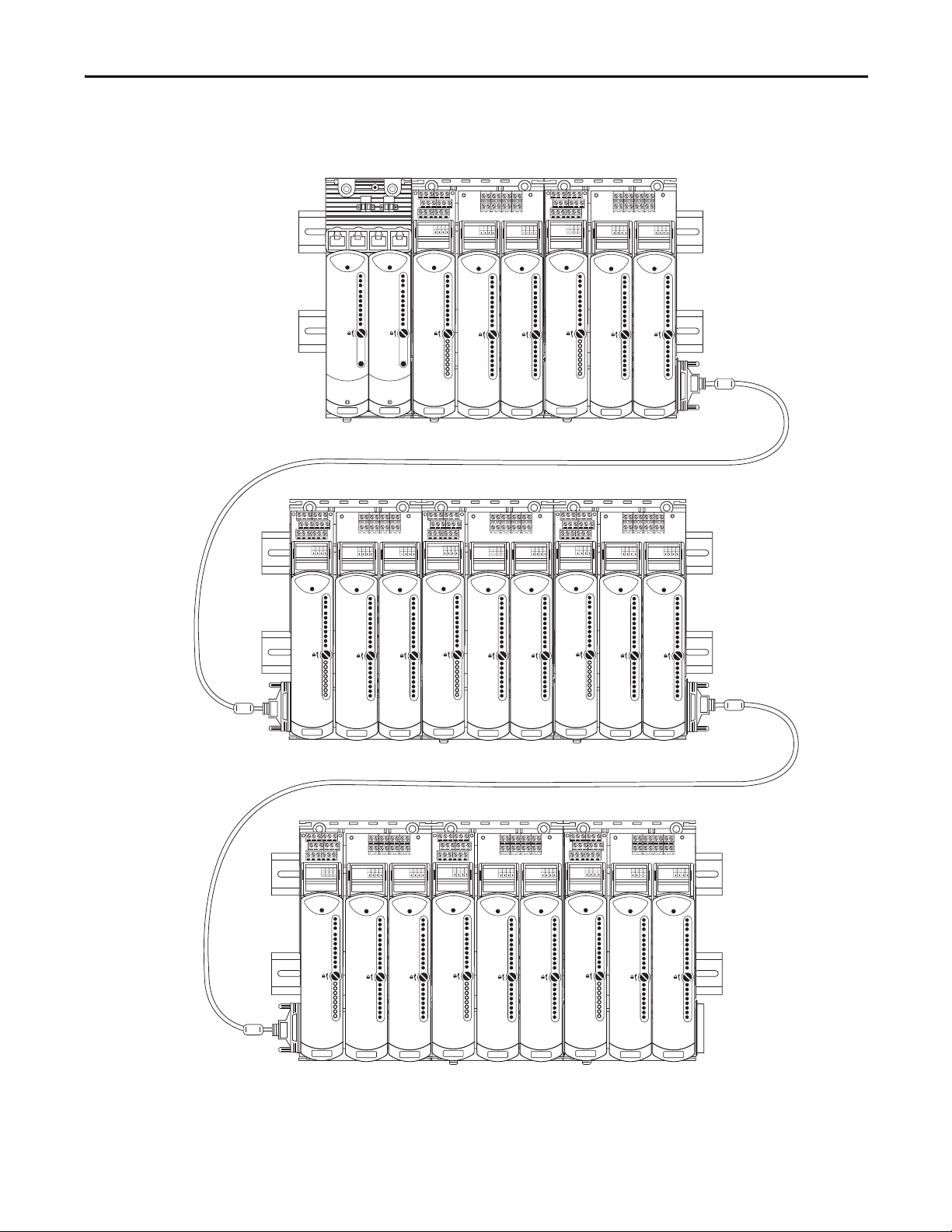
Figure 1 - Example 2 - A Sample System Layout
IO BASE
1715-A310
CH1
CH1
CH1
CH1
CH1
CH1
CH1
CH1
TERMINAL IDENTITY
AOTA
Dual.
CH1
CH1
CH1
CH1
CH1
CH1
CH1
CH1
TERMINAL IDENTITY
AOTA
Dual.
CH1
CH1
CH1
CH1
CH1
CH1
CH1
CH1
TERMINAL IDENTITY
AOTA
Dual.
Channel 00
Channel 01
Channel 02
Channel 03
Channel 04
Channel 05
Channel 06
Channel 07
Channel 00
Channel 01
Channel 02
Channel 03
Channel 04
Channel 05
Channel 06
Channel 07
Channel 08
Channel 09
Channel 10
Channel 11
Channel 12
Channel 13
Channel 14
Channel 15
Channel 00
Channel 01
Channel 02
Channel 03
Channel 04
Channel 05
Channel 06
Channel 07
Channel 08
Channel 09
Channel 10
Channel 11
Channel 12
Channel 13
Channel 14
Channel 15
IO BASE
1715-A310
CH1
CH1
CH1
CH1
CH1
CH1
CH1
CH1
TERMINAL IDENTITY
AOTA
Dual.
CH1
CH1
CH1
CH1
CH1
CH1
CH1
CH1
TERMINAL IDENTITY
AOTA
Dual.
CH1
CH1
CH1
CH1
CH1
CH1
CH1
CH1
TERMINAL IDENTITY
AOTA
Dual.
IO BASE
1715-A310
CH1
CH1
CH1
CH1
CH1
CH1
CH1
CH1
TERMINAL IDENTITY
AOTA
Dual.
CH1
CH1
CH1
CH1
CH1
CH1
CH1
CH1
TERMINAL IDENTITY
AOTA
Dual.
CH1
CH1
CH1
CH1
CH1
CH1
CH1
CH1
TERMINAL IDENTITY
AOTA
Dual.
Module Status
Redundancy Status
Network Status
Rack Status
Ethernet 1
Ethernet 2
Reset
IO BASE
1715-A310
CH1
CH1
CH1
CH1
CH1
CH1
CH1
CH1
TERMINAL IDENTITY
AOTA
Dual.
CH1
CH1
CH1
CH1
CH1
CH1
CH1
CH1
TERMINAL IDENTITY
AOTA
Dual.
CH1
CH1
CH1
CH1
CH1
CH1
CH1
CH1
TERMINAL IDENTITY
AOTA
Dual.
IO BASE
1715-A310
CH1
CH1
CH1
CH1
CH1
CH1
CH1
CH1
TERMINAL IDENTITY
AOTA
Dual.
CH1
CH1
CH1
CH1
CH1
CH1
CH1
CH1
TERMINAL IDENTITY
AOTA
Dual.
CH1
CH1
CH1
CH1
CH1
CH1
CH1
CH1
TERMINAL IDENTITY
AOTA
Dual.
IO BASE
1715-A310
CH1
CH1
CH1
CH1
CH1
CH1
CH1
CH1
TERMINAL IDENTITY
AOTA
Dual.
CH1
CH1
CH1
CH1
CH1
CH1
CH1
CH1
TERMINAL IDENTITY
AOTA
Dual.
CH1
CH1
CH1
CH1
CH1
CH1
CH1
CH1
TERMINAL IDENTITY
AOTA
Dual.
Channel 01
Channel 02
Channel 03
Channel 04
Channel 05
Channel 06
Channel07
Channel 08
IO BASE
1715-A310
CH1
CH1
CH1
CH1
CH1
CH1
CH1
CH1
TERMINAL IDENTITY
AOTA
Dual.
CH1
CH1
CH1
CH1
CH1
CH1
CH1
CH1
TERMINAL IDENTITY
AOTA
Dual.
CH1
CH1
CH1
CH1
CH1
CH1
CH1
CH1
TERMINAL IDENTITY
AOTA
Dual.
Module Status
Redundancy Status
Network Status
Rack Status
Ethernet 1
Ethernet 2
Reset
Healthy
Ready
Run
Healthy
Ready
Run
Healthy
Ready
Run
Healthy
Ready
Run
Healthy
Ready
Run
Healthy
Ready
Run
Healthy
Ready
Run
Healthy
Ready
Run
Healthy
Ready
Run
Healthy
Ready
Run
Healthy
Ready
Run
Healthy
Ready
Run
Healthy
Ready
Run
Healthy
Ready
Run
Healthy
Ready
Run
Healthy
Ready
Run
Healthy
Ready
Run
Healthy
Ready
Run
Healthy
Ready
Run
Healthy
Ready
Run
Healthy
Ready
Run
Healthy
Ready
Run
Healthy
Ready
Run
Healthy
Ready
Run
Channel 00
Channel 01
Channel 02
Channel 03
Channel 04
Channel 05
Channel 06
Channel 07
Channel 00
Channel 01
Channel 02
Channel 03
Channel 04
Channel 05
Channel 06
Channel 07
Channel 08
Channel 09
Channel 10
Channel 11
Channel 12
Channel 13
Channel 14
Channel 15
Channel 00
Channel 01
Channel 02
Channel 03
Channel 04
Channel 05
Channel 06
Channel 07
Channel 08
Channel 09
Channel 10
Channel 11
Channel 12
Channel 13
Channel 14
Channel 15
Channel 00
Channel 01
Channel 02
Channel 03
Channel 04
Channel 05
Channel 06
Channel 07
Channel 08
Channel 09
Channel 10
Channel 11
Channel 12
Channel 13
Channel 14
Channel 15
Channel 00
Channel 01
Channel 02
Channel 03
Channel 04
Channel 05
Channel 06
Channel 07
Channel 00
Channel 01
Channel 02
Channel 03
Channel 04
Channel 05
Channel 06
Channel 07
Channel 08
Channel 09
Channel 10
Channel 11
Channel 12
Channel 13
Channel 14
Channel 15
Channel 00
Channel 01
Channel 02
Channel 03
Channel 04
Channel 05
Channel 06
Channel 07
Channel 08
Channel 09
Channel 10
Channel 11
Channel 12
Channel 13
Channel 14
Channel 15
Channel 00
Channel 01
Channel 02
Channel 03
Channel 04
Channel 05
Channel 06
Channel 07
Channel 08
Channel 09
Channel 10
Channel 11
Channel 12
Channel 13
Channel 14
Channel 15
Channel 00
Channel 01
Channel 02
Channel 03
Channel 04
Channel 05
Channel 06
Channel 07
Channel 00
Channel 01
Channel 02
Channel 03
Channel 04
Channel 05
Channel 06
Channel 07
Channel 08
Channel 09
Channel 10
Channel 11
Channel 12
Channel 13
Channel 14
Channel 15
Channel 00
Channel 01
Channel 02
Channel 03
Channel 04
Channel 05
Channel 06
Channel 07
Channel 08
Channel 09
Channel 10
Channel 11
Channel 12
Channel 13
Channel 14
Channel 15
Channel 00
Channel 01
Channel 02
Channel 03
Channel 04
Channel 05
Channel 06
Channel 07
Channel 08
Channel 09
Channel 10
Channel 11
Channel 12
Channel 13
Channel 14
Channel 15
Channel 00
Channel 01
Channel 02
Channel 03
Channel 04
Channel 05
Channel 06
Channel 07
Channel 00
Channel 01
Channel 02
Channel 03
Channel 04
Channel 05
Channel 06
Channel 07
Channel 08
Channel 09
Channel 10
Channel 11
Channel 12
Channel 13
Channel 14
Channel 15
Channel 00
Channel 01
Channel 02
Channel 03
Channel 04
Channel 05
Channel 06
Channel 07
Channel 08
Channel 09
Channel 10
Channel 11
Channel 12
Channel 13
Channel 14
Channel 15
Channel 00
Channel 01
Channel 02
Channel 03
Channel 04
Channel 05
Channel 06
Channel 07
Channel 08
Channel 09
Channel 10
Channel 11
Channel 12
Channel 13
Channel 14
Channel 15
Channel 00
Channel 01
Channel 02
Channel 03
Channel 04
Channel 05
Channel 06
Channel 07
32066-M
Redundancy System Overview Chapter 1
Rockwell Automation Publication 1715-UM001C-EN-P - March 2014 19
Page 20
Chapter 1 Redundancy System Overview
1756-RM2
1756-EN2TR
IO BASE
1715-A310
CH1
CH1
CH1
CH1
CH1
CH1
CH1
CH1
TERMINAL IDENTITY
AOTA
Dual.
CH1
CH1
CH1
CH1
CH1
CH1
CH1
CH1
TERMINAL IDENTITY
AOTA
Dual.
CH1
CH1
CH1
CH1
CH1
CH1
CH1
CH1
TERMINAL IDENTITY
AOTA
Dual.
IO BASE
1715-A310
CH1
CH1
CH1
CH1
CH1
CH1
CH1
CH1
TERMINAL IDENTITY
AOTA
Dual.
CH1
CH1
CH1
CH1
CH1
CH1
CH1
CH1
TERMINAL IDENTITY
AOTA
Dual.
CH1
CH1
CH1
CH1
CH1
CH1
CH1
CH1
TERMINAL IDENTITY
AOTA
Dual.
1715-AENTR
1756-EN2TR
1756-RM2
1715-AENTR
1715-I/O
1715-I/O
1715-I/O
1715-I/O
1715-I/O
1715-I/O
1756 ControlLogix
Primary Chassis
1756 ControlLogix
Secondary Chassis
1756 RM Cable
1715 Redundant I/O
System
45242
Layout the Hardware
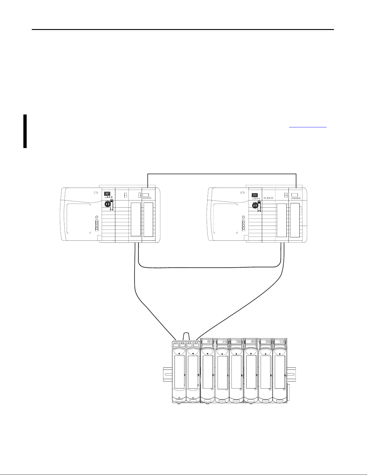
This section discusses how to layout the system’s hardware by topology.
System Context
The redundant I/O subsystem must be connected to one ControlLogix
redundancy system, or any Logix system that supports I/O via the
EtherNet/IP network. All connections are established via the Ethernet network
by using the topologies supported by the 1756-EN2T or 1756-EN2TR module,
that is, DLR (Ring) or Star.
For additional information about DLR topologies, see the EtherNet/IP
Embedded Switch Technology Application Guide, publication ENET-AP005
Figure 2 - 1715 Redundant I/O System DLR (ring) Topology Attached to a 1756 ControlLogix
Enhanced Redundancy System
.
20 Rockwell Automation Publication 1715-UM001C-EN-P - March 2014
Page 21
Redundancy System Overview Chapter 1
1756-RM2
1756-EN2T
IO BASE
1715-A310
CH1
CH1
CH1
CH1
CH1
CH1
CH1
CH1
TERMINAL IDENTITY
AOTA
Dual.
CH1
CH1
CH1
CH1
CH1
CH1
CH1
CH1
TERMINAL IDENTITY
AOTA
Dual.
CH1
CH1
CH1
CH1
CH1
CH1
CH1
CH1
TERMINAL IDENTITY
AOTA
Dual.
IO BASE
1715-A310
CH1
CH1
CH1
CH1
CH1
CH1
CH1
CH1
TERMINAL IDENTITY
AOTA
Dual.
CH1
CH1
CH1
CH1
CH1
CH1
CH1
CH1
TERMINAL IDENTITY
AOTA
Dual.
CH1
CH1
CH1
CH1
CH1
CH1
CH1
CH1
TERMINAL IDENTITY
AOTA
Dual.
1715-AENTR
1756-EN2T
1756-RM2
1715-AENTR
1715-I/O
1715-I/O
1715-I/O
1715-I/O
1715-I/O
1715-I/O
1756 ControlLogix
Secondary Chassis
1756 ControlLogix
Primary Chassis
1715 Redundant I/O
System
1756 RM Cable
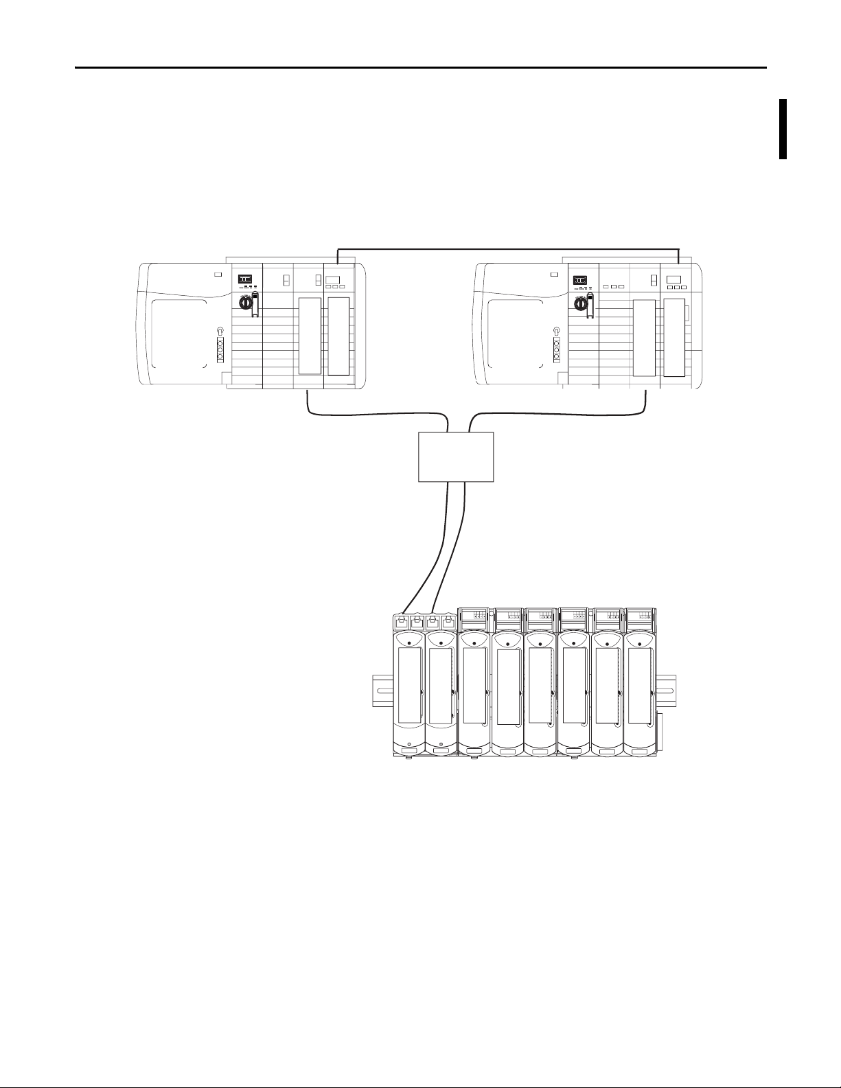
Ethernet
Switch
45239
Figure 3 - 1715 Redundant I/O System Star Topology Attached to a 1756 ControlLogix Enhanced
Redundancy System
Rockwell Automation Publication 1715-UM001C-EN-P - March 2014 21
Page 22
Chapter 1 Redundancy System Overview
IO BASE
1715-A310
CH1
CH1
CH1
CH1
CH1
CH1
CH1
CH1
TERMINAL IDENTITY
AOTA
Dual.
CH1
CH1
CH1
CH1
CH1
CH1
CH1
CH1
TERMINAL IDENTITY
AOTA
Dual.
CH1
CH1
CH1
CH1
CH1
CH1
CH1
CH1
TERMINAL IDENTITY
AOTA
Dual.
1715-AENTR
1715-AENTR
1715-IB16D
1715-OB8DE
ADAPTER
ADAPTER
O/P
I/P
SENSORS
FINAL
ELEMENTS
1715-
TADOB8DE
1715-
TADIB16D
1715-A2A
1715-A3IO
ControlLogix
CIP NETWORK
Digital Output
Simplex Termination
Assembly
Digital Input
Simplex Termination
Assembly
Adapter
Base Unit
I/O Base Units
45241
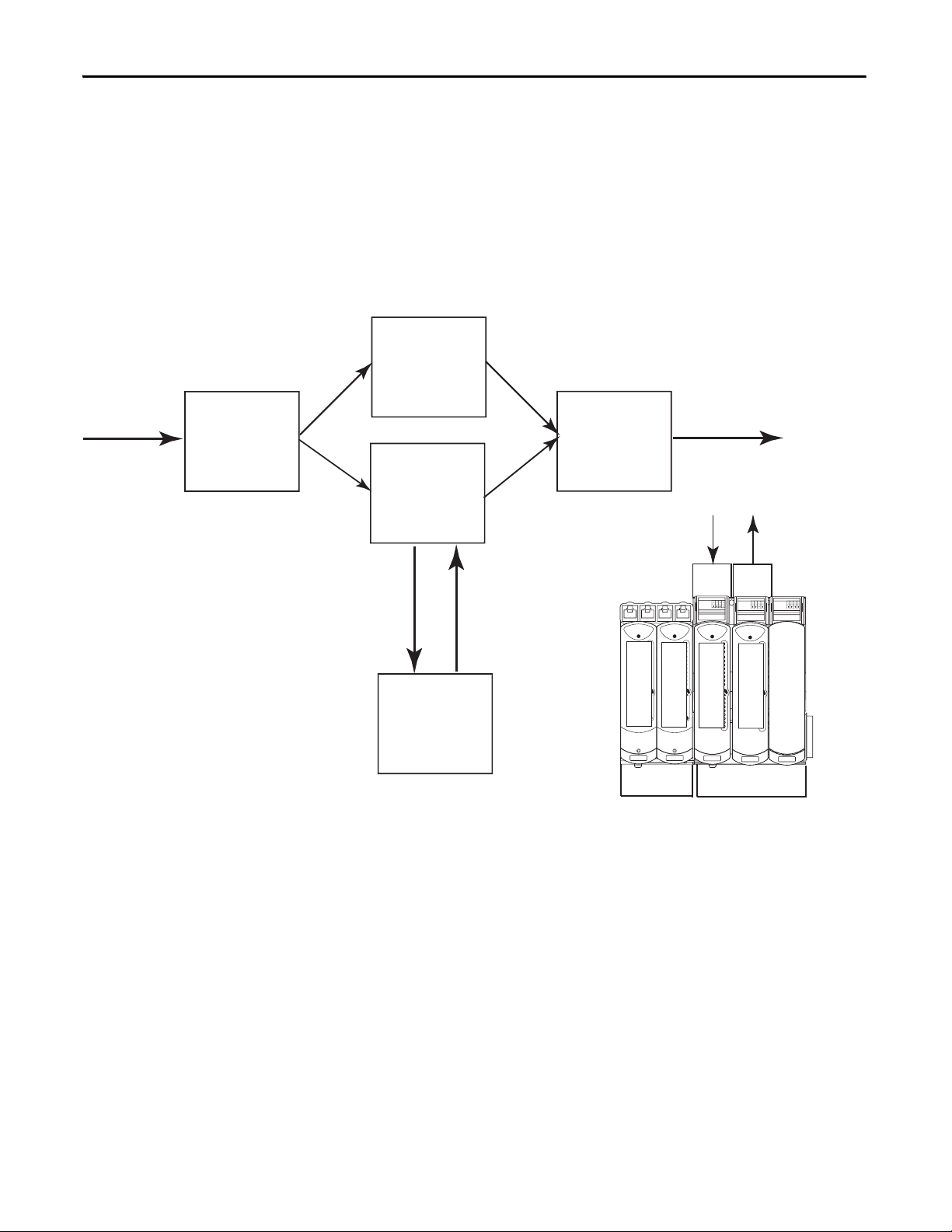
Simplex Architecture
Simplex I/O modules fail safe on the first detected fault. The process under
control shuts down when the fault is detected.
This configuration is suitable for high, as well as low demand module
applications.
Figure 4 - Simplex Architecture - Input and Output
22 Rockwell Automation Publication 1715-UM001C-EN-P - March 2014
Page 23
Redundancy System Overview Chapter 1
ADAPTER
ADAPTER
O/P
I/P
I/P
CLX
CIP NETWORK
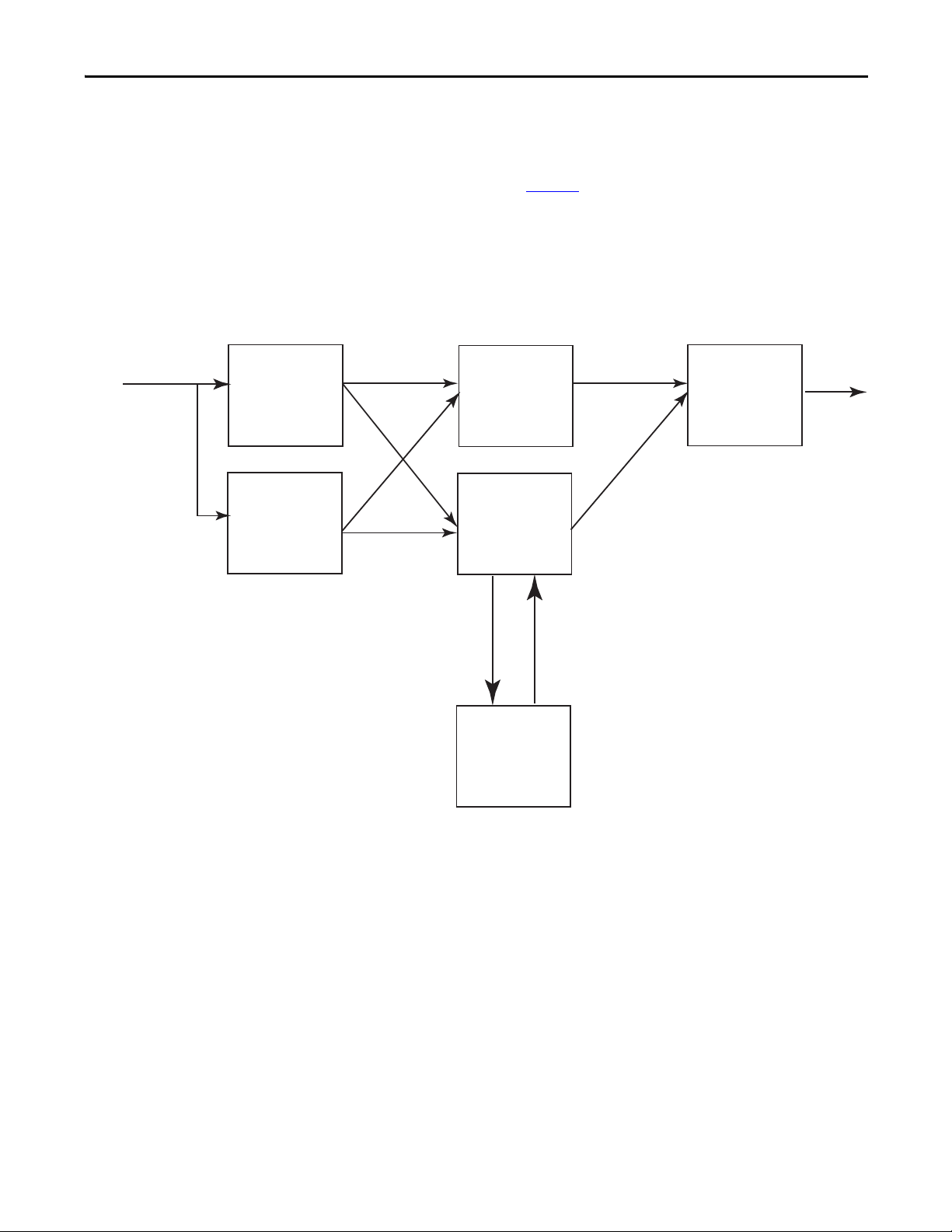
Duplex Architecture
An example configuration of dual input modules and adapters, and a single
output module is shown in Figure 5
module provides fault tolerance for module failures. The duplex arrangement can
be used for low demand and high demand applications.
Figure 5 - Duplex Architecture Duplex Inputs, Simplex Output
. A redundant input or redundant output
Rockwell Automation Publication 1715-UM001C-EN-P - March 2014 23
Page 24

Chapter 1 Redundancy System Overview
1715-AENTR
1715-AENTR
ADAPTER
ADAPTER
O/P
I/P
SENSORS FINAL
ELEMENTS
IO BASE
1715-A310
CH1
CH1
CH1
CH1
CH1
CH1
CH1
CH1
TERMINAL IDENTITY
AOTA
Dual.
CH1
CH1
CH1
CH1
CH1
CH1
CH1
CH1
TERMINAL IDENTITY
AOTA
Dual.
CH1
CH1
CH1
CH1
CH1
CH1
CH1
CH1
TERMINAL IDENTITY
AOTA
Dual.
1715-IB16D
1715-IF16
I/P
O/P
IO BASE
1715-A310
CH1
CH1
CH1
CH1
CH1
CH1
CH1
CH1
TERMINAL IDENTITY
AOTA
Dual.
CH1
CH1
CH1
CH1
CH1
CH1
CH1
CH1
TERMINAL IDENTITY
AOTA
Dual.
CH1
CH1
CH1
CH1
CH1
CH1
CH1
CH1
TERMINAL IDENTITY
AOTA
Dual.
1715-IB16D
1715-IF16
1715-
TADIF16
1715-
TADIB16D
1715-A2A
1715-A3IO
1715-A3IO
CLX
CIP NETWORK
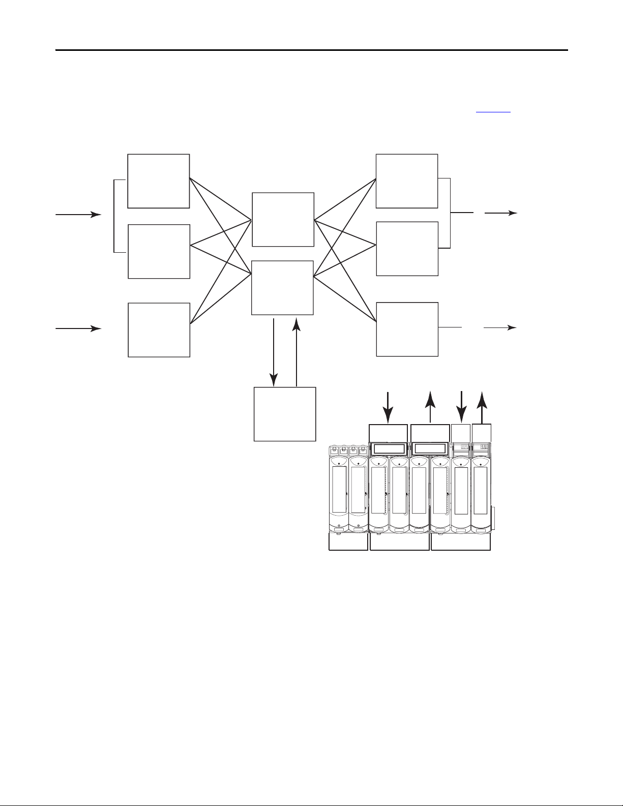
Figure 6 - Duplex Architecture Inputs and Outputs
Note that termination assemblies can span across I/O base units.
24 Rockwell Automation Publication 1715-UM001C-EN-P - March 2014
Page 25
Redundancy System Overview Chapter 1
1715-AENTR
1715-AENTR
ADAPTER
ADAPTER
O/P
SENSORS FINAL
ELEMENTS
IO BASE
1715-A310
CH1
CH1
CH1
CH1
CH1
CH1
CH1
CH1
TERMINAL IDENTITY
AOTA
Dual.
CH1
CH1
CH1
CH1
CH1
CH1
CH1
CH1
TERMINAL IDENTITY
AOTA
Dual.
CH1
CH1
CH1
CH1
CH1
CH1
CH1
CH1
TERMINAL IDENTITY
AOTA
Dual.
1715-IB16D
1715-OB8DE
I/P
O/P
IO BASE
1715-A310
CH1
CH1
CH1
CH1
CH1
CH1
CH1
CH1
TERMINAL IDENTITY
AOTA
Dual.
CH1
CH1
CH1
CH1
CH1
CH1
CH1
CH1
TERMINAL IDENTITY
AOTA
Dual.
CH1
CH1
CH1
CH1
CH1
CH1
CH1
CH1
TERMINAL IDENTITY
AOTA
Dual.
1715-IB16D
1715-OB8DE
1715-
TADOB8DE
1715-
TADIB16D
1715-A2A
1715-A3IO
1715-A3IO
I/P
I/P
O/P
1715-IB16D
FINAL
ELEMENTS
SENSORS
1715-
TASIB16D
1715-
TASOB8DE
1715-OB8DE
CLX
CIP NETWORK
45423
Mixed Architecture
There can be a mixture of architectures within one system. Figure 7 shows
simplex and dual I/O configurations with dual processors.
Figure 7 - Mixed Architecture
Rockwell Automation Publication 1715-UM001C-EN-P - March 2014 25
Page 26
Chapter 1 Redundancy System Overview
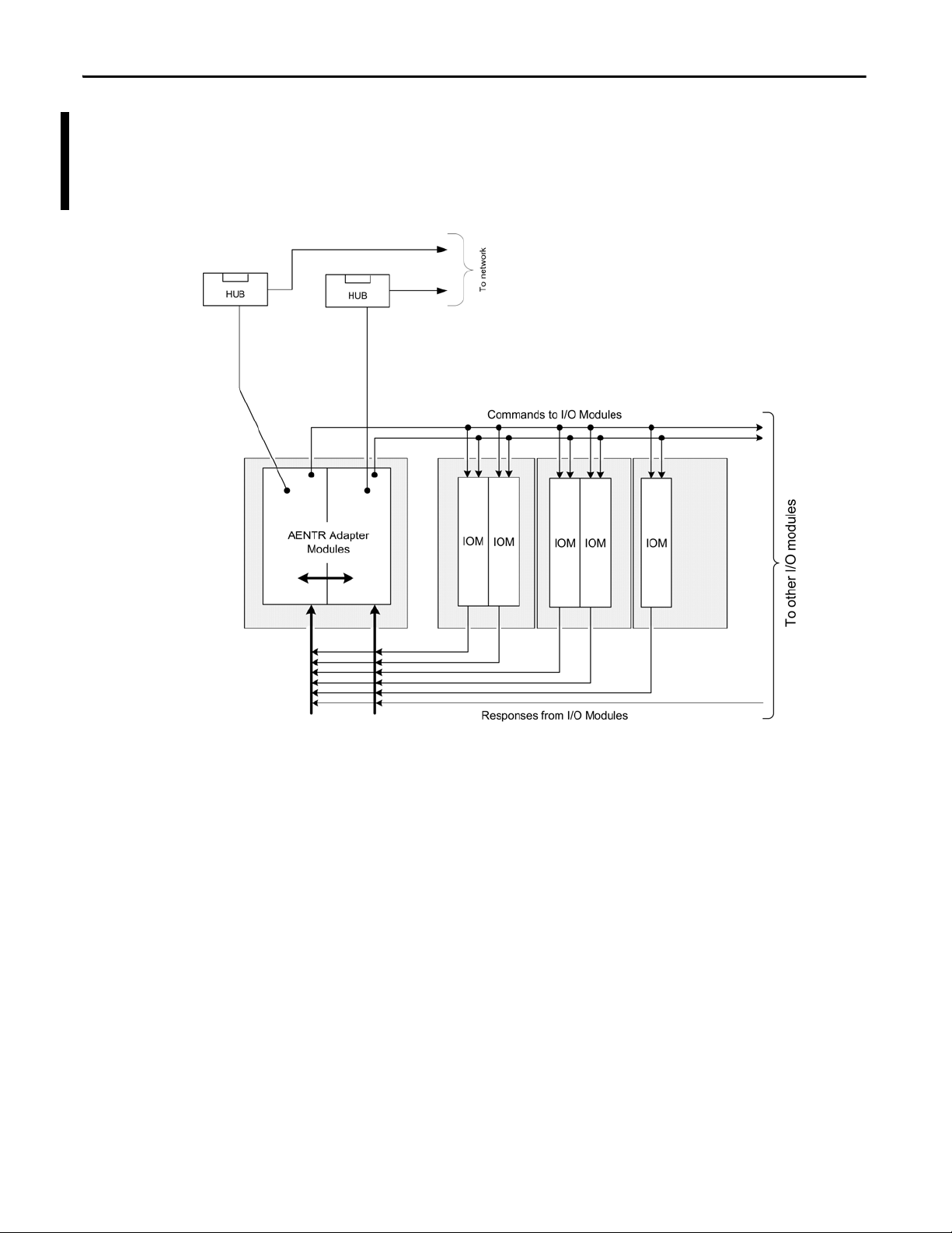
Bus Diagram
A detailed drawing of the backplane is shown below.
Figure 8 - Bus Diagram of 1715 Redundant I/O System
26 Rockwell Automation Publication 1715-UM001C-EN-P - March 2014
Page 27

Redundancy System Overview Chapter 1
Switchover Considerations
Each 1715 Redundant I/O System uses a single IP address as the primary IP
address for all communication on the EtherNet/IP network. The redundant
adapter module pair consists of two active modules, a primary adapter module
and its partner, a secondary module. For the purpose of this document, the
primary module is referred to as module ‘A’ and the secondary module is referred
to as module ‘B’.
On power-up, the adapter module in the leftmost slot is considered the primary
module (when two adapter modules are present) because it uses the primary IP
address, and because it is the module responsible for receiving/transmitting to
ControlLogix controller on the EtherNet/IP network.
The module in the rightmost slot is considered the secondary module partner
and uses the primary IP address +1. For example, if the primary module in the
leftmost slot has an IP address of ‘N’, then the secondary module in the rightmost
slot, has an IP address of ‘N+1’.
Both modules are active at all times and are responsible for monitoring all inputs
and outputs, monitoring diagnostics in the system, and reading and writing data
from/to I/O at exactly the same time. When the primary module receives a write,
it tells the secondary module the data that is to be written, and to which module
it is to be written to. At a synchronized point in time, both adapter modules
physically write to the I/O.
The adapter modules negotiate which module is primary, depending on the
status of the system. If the primary module is unable to perform its role, for
example, if a fault occurs in the primary module, then the secondary module
becomes the new primary, assuming the primary module’s IP address, taking over
the role of communication. The primary module is the only module of the pair
that produces data on the EtherNet/IP network.
In the event of a fault, the IP address swapping between the primary module and
the secondary module takes no longer than 20 ms from the time of the initiating
fault. The secondary module is the new primary and handles all communication.
(Depending on the structure of your Ethernet configuration, this time can be
impacted.)
This IP address swap is transparent to the user. The user can detect which module
the primary module is by looking at the Network status indicator near the top of
each adapter module. On the primary adapter the Network status indicator is
solid green; on the secondary adapter, the Network status indicator flashes green.
Once a swap occurs, the ‘new’ primary module remains the primary unless there’s
a good reason to swap over again. If the B module becomes the primary module
because you need to replace the A module, that is not enough cause to swap IP
addresses back again. Module B remains as the primary module.
Rockwell Automation Publication 1715-UM001C-EN-P - March 2014 27
Page 28

Chapter 1 Redundancy System Overview
Obtaining a New IP Address
The primary module’s IP address is stored in the adapter base unit through
interaction with the TCP/IP object. If a stored primary IP address is available,
the adapter uses that address. If a stored primary IP address is not available, then
the adapter uses BOOTP/DHCP to obtain an IP address.
The adapter transmits DHCP requests, but is able to process a BOOTP/DHCP
response from either a DHCP or BOOTP server. If the BOOTP/DHCP
request is unsuccessful, the secondary adapter module (that is, Module B),
attempts to obtain the primary module’s IP address through BOOTP/DHCP.
The adapters continue to attempt BOOTP/DHCP configuration until an IP
address is obtained, alternating between adapter Modules A and B. Once an
adapter module has obtained the IP address, the secondary module can use that
IP address + 1.
Once an adapter has a primary IP address, it confirms that it does not have a
duplicate IP address. See EtherNet/IP Modules in Logix5000 Control Systems,
publication ENET-UM001
Network Status indicator showing solid RED.
. Duplicated IP addresses are displayed by the
For additional information about assigning an IP address for the first time, see
Chapter 2, Assign an IP Address on page 111
.
28 Rockwell Automation Publication 1715-UM001C-EN-P - March 2014
Page 29

Redundancy System Overview Chapter 1
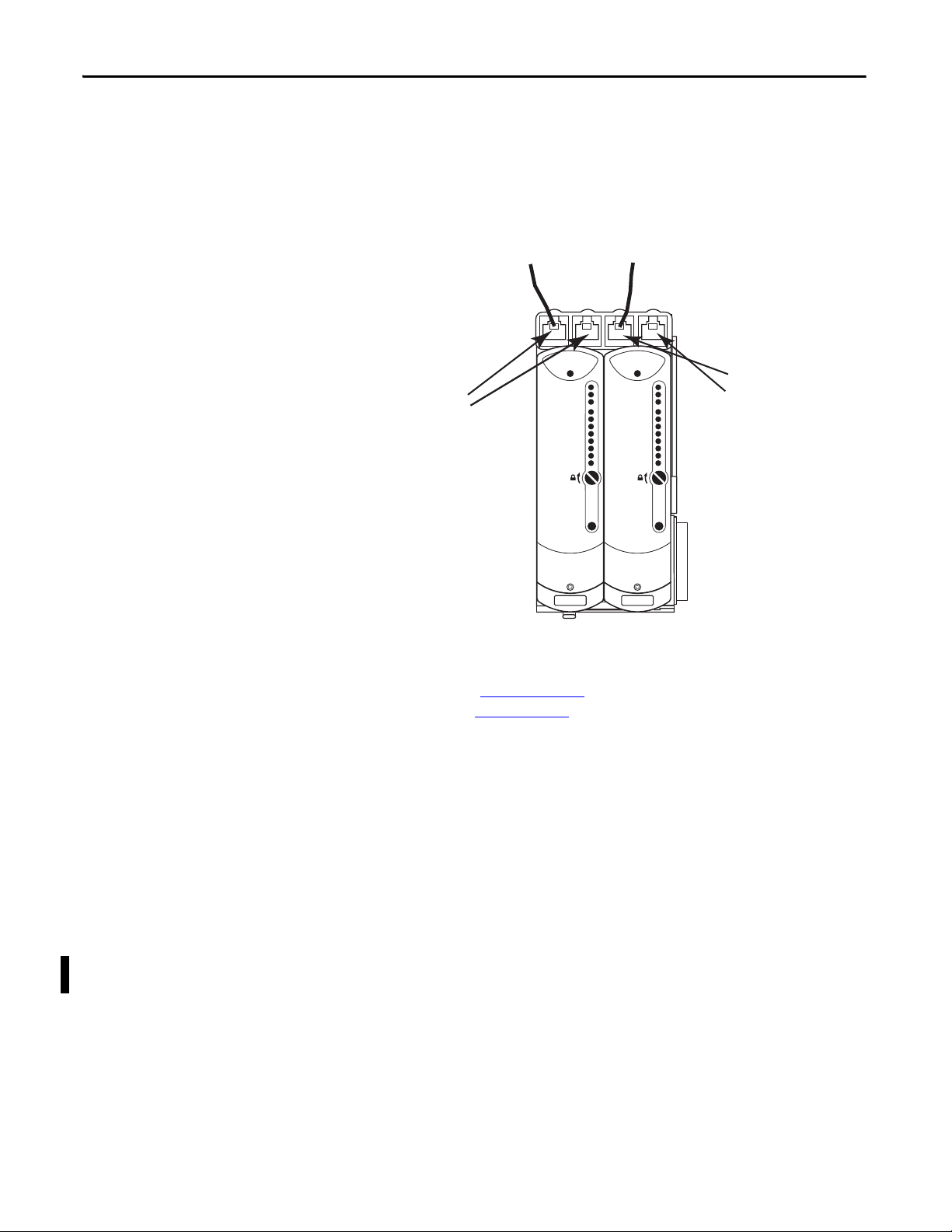
Module Status
Redundancy Status
Network Status
Rack Status
Ethernet 1
Ethernet 2
Reset
Ethernet 1
Ethernet 2
Reset
Module A
Port 1
Port 2
Module B
Port 1
Port 2
Module Status
Redundancy Status
Network Status
Rack Status
Ethernet Topology
The 1715 Redundant I/O System supports DLR (Ring) and Star Topologies.
For a DLR (Ring) Topology, the adapter modules’ Ethernet ports are configured
with the outward-facing ports (Port 1 of Module A and Port 2 of Module B)
operating as a 2-port switch. Port 2 of Module A and Port 1 of Module B are
chained together.
Figure 9 - DLR (Ring) Ethernet Topology
Rockwell Automation Publication 1715-UM001C-EN-P - March 2014 29
Page 30
Chapter 1 Redundancy System Overview
Ethernet 1
Ethernet 2
Reset
Ethernet 1
Ethernet 2
Reset
Module A
Port 1
Port 2
Module B
Port 1
Port 2
Module Status
Redundancy Status
Network Status
Rack Status
Module Status
Redundancy Status
Network Status
Rack Status
45240
For a STAR Topology, the adapter modules’ Ethernet ports are configured with
the leftmost ports (Port 1 of Module A and Port 1of Module B) operating as a
2-port switch. The rightmost ports on each adapter are left unused.
Figure 10 - STAR Ethernet Topology
For Ethernet considerations, see EtherNet/IP Modules in Logix5000 Control
Systems, publication ENET-UM001
System, publication 1756-UM535
, and ControlLogix Enhanced Redundancy
.
Communication on the EtherNet/IP Network
Communication to a simplex module is addressed to the slot number for that
module. CIP communication to modules in a duplex configuration (including
the adapter modules) are addressed to the lowest slot number for the module pair.
The adapter modules respond with CIP errors for attempts to communicate to
an I/O module of a type that is not the same as the physically installed module.
The termination assembly type (simplex/duplex) determines the CIP messages
for corresponding CIP objects that the adapter processes for each I/O module.
30 Rockwell Automation Publication 1715-UM001C-EN-P - March 2014
Page 31

Redundancy System Overview Chapter 1
System Performance
This section discusses connections and RPI settings for the 1715 Redundant I/O
System.
Connections
The adapter module has one required connection and does not support a rack
connection.
Each I/O module has one required connection (simplex or duplex).
For example, the system in Figure 11
one is simplex. They are all configured for data connection.
Figure 11 - Duplex and Simplex Connections
has five I/O modules. Four are duplex and
The example in Figure 11 shows six connections; one for each entry in the
configuration.
Table 4 - RSLogix 5000 or Logix Designer Configuration
Connection Module Duplex/Simplex Module Description
1 1715-AENTR Duplex Ethernet Adapter
1 1715-IB16D Duplex 16-point Digital Input
1 1715-OB8DE Duplex 8-point Diagnostic Digital Output
1 1715-IF16 Duplex 16-point Analog Input
1 1715-OF8I Duplex 8-point Analog Digital Input
1 1715-IF16 Simplex 16-point Analog Input
The digital module connections use change-of state-triggers, and the adapter and
analog module connections use cyclic triggers.
Rockwell Automation Publication 1715-UM001C-EN-P - March 2014 31
Page 32

Chapter 1 Redundancy System Overview
RPI
The RPI you set specifies the maximum amount of time between data updates.
The 1715 modules support an RPI range of 60…750 ms.
Cat. No. Minimum RPI Maximum RPI Default RPI
1715-AENTR 60 ms 750 ms 180 ms
1715-IB16D 60 ms
1715-OB8DE 60 ms
1715-IF16 120 ms
1715-OF8I 120 ms
Connection and Data Format
The adapter and I/O modules each support a single data connection for input/
output data. Listen Only connections are not supported.
32 Rockwell Automation Publication 1715-UM001C-EN-P - March 2014
Page 33

Installation Instructions
Top ic Pa ge
Before You Begin 37
System Hardware Components 39
System S oftware 54
Module Placement 55
Install Summary 58
Product Dimensions 59
DIN Rail Assembly 60
Install the Power Supply 63
Install the Adapter Base Unit 64
Install the I/O Base Unit 64
Install Termination Assembly to I/O Base Unit 67
Mount I/O Expansion Cable 70
Wire the Adapter 76
Connect Field Wiring 79
Connect the Adapter to the Ethernet Network 102
Module Keying 103
Install the Adapter Modules 107
Assign an IP Address 111
Install the I/O Modules 117
Install Slot Filler Covers 120
Remove Modules 121
Chapter 2
This chapter explains how to build the 1715 Redundant I/O System. These
installation instructions include how to build the backplane by connecting the
adapter and I/O base units and mounting them on DIN rails within a cabinet,
how to install and wire the termination assemblies, how to mount the adapter
and the I/O modules onto the system, and how to use expansion cables to allow
for additional space requirements for the system within an enclosure.
Rockwell Automation Publication 1715-UM001C-EN-P - March 2014 33
Page 34

Chapter 2 Installation Instructions
ATTENTION: This equipment is intended for use in a Pollution Degree 2 industrial environment, in overvoltage Category II
applications (as defined in IEC 60664-1), at altitudes up to 2000 m (6562 ft) without derating.
This equipment is not intended for use in residential environments and may not provide adequate protection to radio
communication services in such environments.
This equipment is supplied as open-type equipment. It must be mounted within an enclosure that is suitably designed for
those specific environmental conditions that will be present and appropriately designed to prevent personal injury resulting
from accessibility to live parts. The enclosure must have suitable flame-retardant properties to prevent or minimize the spread
of flame, complying with a flame spread rating of 5VA or be approved for the application if non-metallic. The interior of the
enclosure must be accessible only by the use of a tool. Subsequent sections of this publication may contain additional
information regarding specific enclosure type ratings that are required to comply with certain product safety certifications.
In addition to this publication, see the following:
• Industrial Automation Wiring and Grounding Guidelines, publication
• NEMA Standard 250 and IEC 60529, as applicable, for explanations of the degrees of protection provided by enclosures
Environment and Enclosure
1770-4.1, for additional installation requirements
Prevent Electrostatic Discharge
ATTENTION: This equipment is sensitive to electrostatic discharge, which can cause internal damage and affect normal
operation. Follow these guidelines when you handle this equipment:
• Touch a grounded object to discharge potential static.
• Wear an approved grounding wriststrap.
• Do not touch connectors or pins on component boards.
• Do not touch circuit components inside the equipment.
• Use a static-safe workstation, if available.
• Store the equipment in appropriate static-safe packaging when not in use.
ATTENTION: Do not insert or remove a module, base unit or termination assembly while power is applied. Interruption of
the backplane can result in unintentional operation or machine motion.
ATTENTION: For UL approved installations, the 1715-OB8DE output power source must be isolating, wired with a minimum
of 0.75 mm
2
(18 AWG) wire and fused with a rating of 32V DC min/5 A max.
ATTENTION: Do not wire more than 1 conductor on any single terminal.
ATTENTION: This equipment is not resistant to sunlight or other sources of UV radiation.
34 Rockwell Automation Publication 1715-UM001C-EN-P - March 2014
Page 35

Installation Instructions Chapter 2
European Hazardous Location Approval
The following applies when the product bears the Ex Marking.
This equipment is intended for use in potentially explosive atmospheres as defined by European Union Directive 94/9/EC and has been found to
comply with the Essential Health and Safety Requirements relating to the design and construction of Category 3 equipment intended for use in
Zone 2 potentially explosive atmospheres, given in Annex II to this Directive.
Compliance with the Essential Health and Safety Requirements has been assured by compliance with EN 60079-15 and EN 60079-0.
WARNING:
• This equipment shall be mounted in an ATEX-certified enclosure with a minimum ingress protection rating of at least IP54
(as defined in IEC60529) and used in an environment of not more than Pollution Degree 2 (as defined in IEC 60664-1) when
applied in Zone 2 environments. The enclosure must have a tool-removable cover or door.
• This equipment shall be used within its specified ratings defined by Rockwell Automation.
• Provision shall be made to prevent the rated voltage from being exceeded by transient disturbances of more than 140% of
the rated voltage when applied in Zone 2 environments.
• This equipment must be used only with ATEX certified Rockwell Automation Termination Assemblies.
• Secure any external connections that mate to this equipment by using screws, sliding latches, threaded connectors, or
other means provided with this product.
• Do not disconnect equipment unless power has been removed or the area is known to be nonhazardous.
• Enclosure must be marked with the following: ‘Warning - Do not open when energized.’ After installation of equipment
into the enclosure, access to termination compartments shall be dimensioned so that conductors can be readily connected.
Multi-point Network Communication Connections
WARNING: If you connect or disconnect the communication cable with power applied to this module or any device on the
network, an electrical arc can occur. This could cause an explosion in hazardous location installations.
Be sure that power is removed or the area is nonhazardous before proceeding.
Field-side Power
WARNING: If you connect or disconnect wiring while the field-wire power is on, an electrical arc can occur. This could cause
an explosion in hazardous location installations. Be sure that power is removed or the area is nonhazardous before
proceeding.
Removal and Insertion Under Power (RIUP) Fuses
WARNING: If you insert or remove a base unit or termination assembly while power is applied, an electrical arc can occur.
This could cause an explosion in hazardous location installations.
Be sure that power is removed before proceeding.
WARNING: Do not remove or replace fuses when energized. This could cause an explosion in hazardous location
installations.
Be sure that power is removed or the area is nonhazardous before proceeding.
Rockwell Automation Publication 1715-UM001C-EN-P - March 2014 35
Page 36

Chapter 2 Installation Instructions
North American Hazardous Location Approval
The following information applies when operating this equipment in hazardous
locations.
Products marked ‘CL I, DIV 2, GP A, B, C, D’ are suitable for use in Class I
Division 2 Groups A, B, C, D, Hazardous Locations and nonhazardous
locations only. Each product is supplied with markings on the rating
nameplate indicating the hazardous location temperature code. When
combining products within a system, the most adverse temperature
code (lowest ‘T’ number) be used to help determine the overall
temperature code of the system. Combinations of equipment in your
system are subject to investigation by the local Authority Having
Jurisdiction at the time of installation.
EXPLOSION HAZARD
• Do not disconnect equipment unless
power has been removed or the area is
known to be nonhazardous.
• Do not disconnect connections to this
equipment unless power has been
removed or the area is known to be
nonhazardous. Secure any external
connections that mate to this equipment
by using screws, sliding latches, threaded
connectors, or other means provided with
this product.
• Substitution of components may impair
suitability for Class I, Division 2.
• If this product contains batteries, they
must only be changed in an area known to
be nonhazardous.
Informations sur l'utilisation de cet équipement en environnements
dangereux.
Les produits marqués ‘CL I, DIV 2, GP A, B, C, D’ ne conviennent qu'à
une utilisation en environnements de Classe I Division 2 Groupes A,
B, C, D dangereux et non dangereux. Chaque produit est livré avec
des marquages sur sa plaque d'identification qui indiquent le code
de température pour les environnements dangereux. Lorsque
plusieurs produits sont combinés dans un système, le code de
température le plus défavorable (code de température le plus faible)
peut être utilisé pour déterminer le code de température global du
système. Les combinaisons d'équipements dans le système sont
sujettes à inspection par les autorités locales qualifiées au moment
de l'installation.
RISQUE D’EXPLOSION –
• Couper le courant ou s'assurer que
l'environnement est classé non
dangereux avant de débrancher
l'équipement.
• Couper le courant ou s'assurer que
l'environnement est classé non
dangereux avant de débrancher les
connecteurs. Fixer tous les
connecteurs externes reliés à cet
équipement à l'aide de vis, loquets
coulissants, connecteurs filetés ou
autres moyens fournis avec ce
produit.
• La substitution de composants peut
rendre cet équipement inadapté à
une utilisation en environnement de
Classe I, Division 2.
• S'assurer que l'environnement est
classé non dangereux avant de
changer les piles.
36 Rockwell Automation Publication 1715-UM001C-EN-P - March 2014
Page 37

Installation Instructions Chapter 2
IMPORTANT
Before You Begin
This section lists important information you need to consider before starting to
build your 1715 Redundant I/O System:
• Review the parts list and identify the system components.
• Review the power requirements for the system and for field devices.
• Review design considerations for heating and cooling.
• Specify an enclosure.
• Install the necessary software.
Please note that throughout this manual, some graphics do not depict the
actual hardware as required. These graphics are for representational purposes
only and do not necessarily reflect the actual component layout of your system.
Parts List
These parts are available to build a 1715 Redundant I/O System. Their
description and catalog part numbers are as follows.
Table 5 - Par ts Table
Cat. No. Description
1715-AENTR Adapter module
1715-IB16D 16-channel digital input module
1715-OB8DE 8-channel digital output module
1715-IF16 16-channel analog input module
1715-OF8I 8-channel analog output module
1715-A2A 2-slot adapter base unit
1715-A3IO 3-slot I/O base unit
1715-TASIB16D Termination assembly - digital input simplex
1715-TADIB16D Termination assembly - digital input duplex
1715-TASOB8DE Termination assembly - digital output simplex
1715-TADOB8DE Termination assembly - digital output duplex
1715-TASIF16 Termination assembly - analog input simplex
1715-TADIF16 Termination assembly - analog input duplex
1715-TASOF8 Termination assembly - analog output simplex
1715-TADOF8 Termination assembly - analog output duplex
1715-N2T Tall slot filler cover
1715-N2S Short slot filler cover
1715-C2 Expansion cable - 2 m
Rockwell Automation Publication 1715-UM001C-EN-P - March 2014 37
Page 38

Chapter 2 Installation Instructions
IMPORTANT
IMPORTANT
Wireway
IO BASE
1715-A310
CH1
CH1
CH1
CH1
CH1
CH1
CH1
CH1
TERMINAL IDENTITY
AOTA
Dual.
CH1
CH1
CH1
CH1
CH1
CH1
CH1
CH1
TERMINAL IDENTITY
AOTA
Dual.
CH1
CH1
CH1
CH1
CH1
CH1
CH1
CH1
TERMINAL IDENTITY
AOTA
Dual.
Ethernet 1
Ethernet 2
Reset
Ethernet 1
Ethernet 2
Reset
Channel 01
Channel 02
Channel 03
Channel 04
Channel 05
Channel 06
Channel07
Channel 08
Channel 01
Channel 02
Channel 03
Channel 04
Channel 05
Channel 06
Channel07
Channel 08
Channel 09
Channel 10
Channel 11
Channel 12
Channel 13
Channel 14
Channel15
Channel 16
Channel 01
Channel 02
Channel 03
Channel 04
Channel 05
Channel 06
Channel07
Channel 08
Channel 09
Channel 10
Channel 11
Channel 12
Channel 13
Channel 14
Channel15
Channel 16
IO BASE
1715-A310
CH1
CH1
CH1
CH1
CH1
CH1
CH1
CH1
TERMINAL IDENTITY
AOTA
Dual.
CH1
CH1
CH1
CH1
CH1
CH1
CH1
CH1
TERMINAL IDENTITY
AOTA
Dual.
CH1
CH1
CH1
CH1
CH1
CH1
CH1
CH1
TERMINAL IDENTITY
AOTA
Dual.
Channel 01
Channel 02
Channel 03
Channel 04
Channel 05
Channel 06
Channel07
Channel 08
Channel 01
Channel 02
Channel 03
Channel 04
Channel 05
Channel 06
Channel07
Channel 08
Channel 09
Channel 10
Channel 11
Channel 12
Channel 13
Channel 14
Channel15
Channel 16
Channel 01
Channel 02
Channel 03
Channel 04
Channel 05
Channel 06
Channel07
Channel 08
Channel 09
Channel 10
Channel 11
Channel 12
Channel 13
Channel 14
Channel15
Channel 16
Module Status
Redundancy Status
Network Status
Rack Status
Module Status
Redundancy Status
Network Status
Rack Status
Healthy
Ready
Run
Healthy
Ready
Run
Healthy
Ready
Run
Healthy
Ready
Run
Healthy
Ready
Run
Healthy
Ready
Run
IO BASE
1715-A310
CH1
CH1
CH1
CH1
CH1
CH1
CH1
CH1
TERMINAL IDENTITY
AOTA
Dual.
CH1
CH1
CH1
CH1
CH1
CH1
CH1
CH1
TERMINAL IDENTITY
AOTA
Dual.
CH1
CH1
CH1
CH1
CH1
CH1
CH1
CH1
TERMINAL IDENTITY
AOTA
Dual.
Ethernet 1
Ethernet 2
Reset
Ethernet 1
Ethernet 2
Reset
Channel 01
Channel 02
Channel 03
Channel 04
Channel 05
Channel 06
Channel07
Channel 08
Channel 01
Channel 02
Channel 03
Channel 04
Channel 05
Channel 06
Channel07
Channel 08
Channel 09
Channel 10
Channel 11
Channel 12
Channel 13
Channel 14
Channel15
Channel 16
Channel 01
Channel 02
Channel 03
Channel 04
Channel 05
Channel 06
Channel07
Channel 08
Channel 09
Channel 10
Channel 11
Channel 12
Channel 13
Channel 14
Channel15
Channel 16
IO BASE
1715-A310
CH1
CH1
CH1
CH1
CH1
CH1
CH1
CH1
TERMINAL IDENTITY
AOTA
Dual.
CH1
CH1
CH1
CH1
CH1
CH1
CH1
CH1
TERMINAL IDENTITY
AOTA
Dual.
CH1
CH1
CH1
CH1
CH1
CH1
CH1
CH1
TERMINAL IDENTITY
AOTA
Dual.
Channel 01
Channel 02
Channel 03
Channel 04
Channel 05
Channel 06
Channel07
Channel 08
Channel 01
Channel 02
Channel 03
Channel 04
Channel 05
Channel 06
Channel07
Channel 08
Channel 09
Channel 10
Channel 11
Channel 12
Channel 13
Channel 14
Channel15
Channel 16
Channel 01
Channel 02
Channel 03
Channel 04
Channel 05
Channel 06
Channel07
Channel 08
Channel 09
Channel 10
Channel 11
Channel 12
Channel 13
Channel 14
Channel15
Channel 16
Module Status
Redundancy Status
Network Status
Rack Status
Module Status
Redundancy Status
Network Status
Rack Status
Healthy
Ready
Run
Healthy
Ready
Run
Healthy
Ready
Run
Healthy
Ready
Run
Healthy
Ready
Run
Healthy
Ready
Run
IO BASE
1715-A310
CH1
CH1
CH1
CH1
CH1
CH1
CH1
CH1
TERMINAL IDENTITY
AOTA
Dual.
CH1
CH1
CH1
CH1
CH1
CH1
CH1
CH1
TERMINAL IDENTITY
AOTA
Dual.
CH1
CH1
CH1
CH1
CH1
CH1
CH1
CH1
TERMINAL IDENTITY
AOTA
Dual.
Ethernet 1
Ethernet 2
Reset
Ethernet 1
Ethernet 2
Reset
Channel 01
Channel 02
Channel 03
Channel 04
Channel 05
Channel 06
Channel07
Channel 08
Channel 01
Channel 02
Channel 03
Channel 04
Channel 05
Channel 06
Channel07
Channel 08
Channel 09
Channel 10
Channel 11
Channel 12
Channel 13
Channel 14
Channel15
Channel 16
Channel 01
Channel 02
Channel 03
Channel 04
Channel 05
Channel 06
Channel07
Channel 08
Channel 09
Channel 10
Channel 11
Channel 12
Channel 13
Channel 14
Channel15
Channel 16
IO BASE
1715-A310
CH1
CH1
CH1
CH1
CH1
CH1
CH1
CH1
TERMINAL IDENTITY
AOTA
Dual.
CH1
CH1
CH1
CH1
CH1
CH1
CH1
CH1
TERMINAL IDENTITY
AOTA
Dual.
CH1
CH1
CH1
CH1
CH1
CH1
CH1
CH1
TERMINAL IDENTITY
AOTA
Dual.
Channel 01
Channel 02
Channel 03
Channel 04
Channel 05
Channel 06
Channel07
Channel 08
Channel 01
Channel 02
Channel 03
Channel 04
Channel 05
Channel 06
Channel07
Channel 08
Channel 09
Channel 10
Channel 11
Channel 12
Channel 13
Channel 14
Channel15
Channel 16
Channel 01
Channel 02
Channel 03
Channel 04
Channel 05
Channel 06
Channel07
Channel 08
Channel 09
Channel 10
Channel 11
Channel 12
Channel 13
Channel 14
Channel15
Channel 16
Module Status
Redundancy Status
Network Status
Rack Status
Module Status
Redundancy Status
Network Status
Rack Status
Healthy
Ready
Run
Healthy
Ready
Run
Healthy
Ready
Run
Healthy
Ready
Run
Healthy
Ready
Run
Healthy
Ready
Run
IO BASE
1715-A310
CH1
CH1
CH1
CH1
CH1
CH1
CH1
CH1
TERMINAL IDENTITY
AOTA
Dual.
CH1
CH1
CH1
CH1
CH1
CH1
CH1
CH1
TERMINAL IDENTITY
AOTA
Dual.
CH1
CH1
CH1
CH1
CH1
CH1
CH1
CH1
TERMINAL IDENTITY
AOTA
Dual.
Ethernet 1
Ethernet 2
Reset
Ethernet 1
Ethernet 2
Reset
Channel 01
Channel 02
Channel 03
Channel 04
Channel 05
Channel 06
Channel07
Channel 08
Channel 01
Channel 02
Channel 03
Channel 04
Channel 05
Channel 06
Channel07
Channel 08
Channel 09
Channel 10
Channel 11
Channel 12
Channel 13
Channel 14
Channel15
Channel 16
Channel 01
Channel 02
Channel 03
Channel 04
Channel 05
Channel 06
Channel07
Channel 08
Channel 09
Channel 10
Channel 11
Channel 12
Channel 13
Channel 14
Channel15
Channel 16
IO BASE
1715-A310
CH1
CH1
CH1
CH1
CH1
CH1
CH1
CH1
TERMINAL IDENTITY
AOTA
Dual.
CH1
CH1
CH1
CH1
CH1
CH1
CH1
CH1
TERMINAL IDENTITY
AOTA
Dual.
CH1
CH1
CH1
CH1
CH1
CH1
CH1
CH1
TERMINAL IDENTITY
AOTA
Dual.
Channel 01
Channel 02
Channel 03
Channel 04
Channel 05
Channel 06
Channel07
Channel 08
Channel 01
Channel 02
Channel 03
Channel 04
Channel 05
Channel 06
Channel07
Channel 08
Channel 09
Channel 10
Channel 11
Channel 12
Channel 13
Channel 14
Channel15
Channel 16
Channel 01
Channel 02
Channel 03
Channel 04
Channel 05
Channel 06
Channel07
Channel 08
Channel 09
Channel 10
Channel 11
Channel 12
Channel 13
Channel 14
Channel15
Channel 16
Module Status
Redundancy Status
Network Status
Rack Status
Module Status
Redundancy Status
Network Status
Rack Status
Healthy
Ready
Run
Healthy
Ready
Run
Healthy
Ready
Run
Healthy
Ready
Run
Healthy
Ready
Run
Healthy
Ready
Run
IO BASE
1715-A310
CH1
CH1
CH1
CH1
CH1
CH1
CH1
CH1
TERMINAL IDENTITY
AOTA
Dual.
CH1
CH1
CH1
CH1
CH1
CH1
CH1
CH1
TERMINAL IDENTITY
AOTA
Dual.
CH1
CH1
CH1
CH1
CH1
CH1
CH1
CH1
TERMINAL IDENTITY
AOTA
Dual.
Ethernet 1
Ethernet 2
Reset
Ethernet 1
Ethernet 2
Reset
Channel 01
Channel 02
Channel 03
Channel 04
Channel 05
Channel 06
Channel07
Channel 08
Channel 01
Channel 02
Channel 03
Channel 04
Channel 05
Channel 06
Channel07
Channel 08
Channel 09
Channel 10
Channel 11
Channel 12
Channel 13
Channel 14
Channel15
Channel 16
Channel 01
Channel 02
Channel 03
Channel 04
Channel 05
Channel 06
Channel07
Channel 08
Channel 09
Channel 10
Channel 11
Channel 12
Channel 13
Channel 14
Channel15
Channel 16
IO BASE
1715-A310
CH1
CH1
CH1
CH1
CH1
CH1
CH1
CH1
TERMINAL IDENTITY
AOTA
Dual.
CH1
CH1
CH1
CH1
CH1
CH1
CH1
CH1
TERMINAL IDENTITY
AOTA
Dual.
CH1
CH1
CH1
CH1
CH1
CH1
CH1
CH1
TERMINAL IDENTITY
AOTA
Dual.
Channel 01
Channel 02
Channel 03
Channel 04
Channel 05
Channel 06
Channel07
Channel 08
Channel 01
Channel 02
Channel 03
Channel 04
Channel 05
Channel 06
Channel07
Channel 08
Channel 09
Channel 10
Channel 11
Channel 12
Channel 13
Channel 14
Channel15
Channel 16
Channel 01
Channel 02
Channel 03
Channel 04
Channel 05
Channel 06
Channel07
Channel 08
Channel 09
Channel 10
Channel 11
Channel 12
Channel 13
Channel 14
Channel15
Channel 16
Module Status
Redundancy Status
Network Status
Rack Status
Module Status
Redundancy Status
Network Status
Rack Status
Healthy
Ready
Run
Healthy
Ready
Run
Healthy
Ready
Run
Healthy
Ready
Run
Healthy
Ready
Run
Healthy
Ready
Run
IO BASE
1715-A310
CH1
CH1
CH1
CH1
CH1
CH1
CH1
CH1
TERMINAL IDENTITY
AOTA
Dual.
CH1
CH1
CH1
CH1
CH1
CH1
CH1
CH1
TERMINAL IDENTITY
AOTA
Dual.
CH1
CH1
CH1
CH1
CH1
CH1
CH1
CH1
TERMINAL IDENTITY
AOTA
Dual.
Ethernet 1
Ethernet 2
Reset
Ethernet 1
Ethernet 2
Reset
Channel 01
Channel 02
Channel 03
Channel 04
Channel 05
Channel 06
Channel07
Channel 08
Channel 01
Channel 02
Channel 03
Channel 04
Channel 05
Channel 06
Channel07
Channel 08
Channel 09
Channel 10
Channel 11
Channel 12
Channel 13
Channel 14
Channel15
Channel 16
Channel 01
Channel 02
Channel 03
Channel 04
Channel 05
Channel 06
Channel07
Channel 08
Channel 09
Channel 10
Channel 11
Channel 12
Channel 13
Channel 14
Channel15
Channel 16
IO BASE
1715-A310
CH1
CH1
CH1
CH1
CH1
CH1
CH1
CH1
TERMINAL IDENTITY
AOTA
Dual.
CH1
CH1
CH1
CH1
CH1
CH1
CH1
CH1
TERMINAL IDENTITY
AOTA
Dual.
CH1
CH1
CH1
CH1
CH1
CH1
CH1
CH1
TERMINAL IDENTITY
AOTA
Dual.
Channel 01
Channel 02
Channel 03
Channel 04
Channel 05
Channel 06
Channel07
Channel 08
Channel 01
Channel 02
Channel 03
Channel 04
Channel 05
Channel 06
Channel07
Channel 08
Channel 09
Channel 10
Channel 11
Channel 12
Channel 13
Channel 14
Channel15
Channel 16
Channel 01
Channel 02
Channel 03
Channel 04
Channel 05
Channel 06
Channel07
Channel 08
Channel 09
Channel 10
Channel 11
Channel 12
Channel 13
Channel 14
Channel15
Channel 16
Module Status
Redundancy Status
Network Status
Rack Status
Module Status
Redundancy Status
Network Status
Rack Status
Healthy
Ready
Run
Healthy
Ready
Run
Healthy
Ready
Run
Healthy
Ready
Run
Healthy
Ready
Run
Healthy
Ready
Run
15.3 (6.0)
10.2 (4.0)
15.3…20 (6.0…8.0)
10.2 (4.0)
5.1 (2.0)
5.1 (2.0)
15.3 (6.0)
7.7…10.2
(3.0…4.0)
Required Tools
The installation and maintenance of the 1715 Redundant I/O System requires
these tools:
• Screwdriver, 0.8 x 9.0 mm (1/25 x 3/8 in.), for module clamp screws and
slot filler covers
• Torque screw driver, 0.6 x 3.0 mm (1/40 x 1/8 in.), for DC power wiring
terminals
• Torque screwdriver, 0.4 x 2.0 mm (1/64 x 5/64 in.), for field wiring
terminals
• Two open-end wrenches, 10 mm (0.39 in.), for ground stud nuts
• A 2.5 mm (0.10 in.) Allen wrench
Spacing Requirements
You must consider spacing requirements before mounting your system.
Make sure you meet the minimum spacing requirements shown.
Allow 15.3…20 cm (6.0…8.0 in.) between chassis and a heat source, and
chassis and cabinet, and allow 5.1 cm (2.0 in.) between wire way and top or
bottom of chassis.
Dimensions are in cm (in.).
Figure 12 - Cabinet
When installing the system in a chassis, note that chassis are intended to be
mounted horizontally only. The modules are to be installed in the chassis in a
vertical orientation only.
38 Rockwell Automation Publication 1715-UM001C-EN-P - March 2014
Page 39

Installation Instructions Chapter 2
IMPORTANT
IO BASE
1715-A310
CH1
CH1
CH1
CH1
CH1
CH1
CH1
CH1
TERMINAL IDENTITY
AOTA
Dual.
CH1
CH1
CH1
CH1
CH1
CH1
CH1
CH1
TERMINAL IDENTITY
AOTA
Dual.
CH1
CH1
CH1
CH1
CH1
CH1
CH1
CH1
TERMINAL IDENTITY
AOTA
Dual.
Ethernet 1
Ethernet 2
Reset
Ethernet 1
Ethernet 2
Reset
Channel 00
Channel 01
Channel 02
Channel 03
Channel 04
Channel 05
Channel 06
Channel 07
Channel 08
Channel 09
Channel 10
Channel 11
Channel 12
Channel 13
Channel 14
Channel 15
IO BASE
1715-A310
CH1
CH1
CH1
CH1
CH1
CH1
CH1
CH1
TERMINAL IDENTITY
AOTA
Dual.
CH1
CH1
CH1
CH1
CH1
CH1
CH1
CH1
TERMINAL IDENTITY
AOTA
Dual.
CH1
CH1
CH1
CH1
CH1
CH1
CH1
CH1
TERMINAL IDENTITY
AOTA
Dual.
Module Status
Redundancy Status
Network Status
Rack Status
Module Status
Redundancy Status
Network Status
Rack Status
Healthy
Ready
Run
Healthy
Ready
Run
Healthy
Ready
Run
Healthy
Ready
Run
Healthy
Ready
Run
Healthy
Ready
Run
Channel 00
Channel 01
Channel 02
Channel 03
Channel 04
Channel 05
Channel 06
Channel 07
Channel 08
Channel 09
Channel 10
Channel 11
Channel 12
Channel 13
Channel 14
Channel 15
Channel 00
Channel 01
Channel 02
Channel 03
Channel 04
Channel 05
Channel 06
Channel 07
Channel 00
Channel 01
Channel 02
Channel 03
Channel 04
Channel 05
Channel 06
Channel 07
Channel 08
Channel 09
Channel 10
Channel 11
Channel 12
Channel 13
Channel 14
Channel 15
Channel 00
Channel 01
Channel 02
Channel 03
Channel 04
Channel 05
Channel 06
Channel 07
Channel 08
Channel 09
Channel 10
Channel 11
Channel 12
Channel 13
Channel 14
Channel 15
Channel 00
Channel 01
Channel 02
Channel 03
Channel 04
Channel 05
Channel 06
Channel 07
32065-M
System Hardware Components
The 1715 Redundant I/O System is a remote redundant I/O system developed
to communicate with a Logix controller in a ControlLogix enhanced redundant
system by using the EtherNet/IP network and includes these components:
• A pair of 1715-AENTR adapter modules serve as a ‘proxy’ for all
EtherNet/IP messages to and from redundant I/O modules.
• 1715 digital and analog I/O modules.
• A 1715-A2A dual redundant I/O adapter base unit connects to a
1715-A3I0 I/O module base unit to form the backplane for the system.
• Termination assemblies configured in either Simplex or Duplex mode
mount onto the base units to allow communication between the modules
and the backplane. Each I/O module uses either a simplex termination
assembly or a duplex termination assembly, depending on the mode
needed.
• Each 1715-A3IO I/O base unit holds up to three I/O modules. Up to
24 I/O modules can be added to the system.
• The system is built on DIN rails within a cabinet enclosure.
• 1715-C2 expansion cables can be used to allow for space restrictions of the
system within the cabinet.
Conformal coating is standard on all 1715 modules.
Rockwell Automation Publication 1715-UM001C-EN-P - March 2014 39
Page 40

Chapter 2 Installation Instructions
Rack Status
Ethernet 1
Ethernet 2
1715-AENTR
ADAPTER
Reset
Module Status
Redundancy Status
Network Status
32096-M
Do not open this module door, or plug or
insert anything into the port.
32096-M
Rack Status
Ethernet 1
Ethernet 2
1715-AENTR
ADAPTER
Reset
Module Status
Redundancy Status
Network Status
32096-M
Rack Status
Ethernet 1
Ethernet 2
1715-AENTR
ADAPTER
Reset
Module Status
Redundancy Status
Network Status
1715-AENTR Redundant
Adapter Module Pair
IMPORTANT
The general system layout for the 1715 Redundant I/O System consists of the
following hardware components.
1715-AENTR Adapter Redundant Module Pair
The 1715 adapter module communicates via the EtherNet/IP network to a 1756
ControlLogix controller, conveying system I/O data.
Figure 13 - 1715-AENTR Adapter Module
Do not open this module door, or plug or insert anything into the port behind
the module door unless instructed to do so by technical support.
40 Rockwell Automation Publication 1715-UM001C-EN-P - March 2014
Page 41

Installation Instructions Chapter 2
Healthy
Ready
Run
Channel 00
Channel 01
Channel 02
Channel 03
Channel 04
Channel 05
Channel 06
Channel 07
1715-IB16D
DIGITAL INPUT
Channel 08
Channel 09
Channel 10
Channel 11
Channel 12
Channel 13
Channel 14
Channel 15
Channel 00
Channel 01
Channel 02
Channel 03
Channel 04
Channel 05
Channel 06
Channel 07
1715-OB8DE
DIGITAL OUTPUT
Healthy
Ready
Run
Channel 00
Channel 01
Channel 02
Channel 03
Channel 04
Channel 05
Channel 06
Channel 07
1715-IF16
ANALOG INPUT
Channel 08
Channel 09
Channel 10
Channel 11
Channel 12
Channel 13
Channel 14
Channel 15
Healthy
Ready
Run
Channel 00
Channel 01
Channel 02
Channel 03
Channel 04
Channel 05
Channel 06
Channel 07
1715-OF8I
ANALOG OUTPUT
Healthy
Ready
Run
1715-IB16D 16-channel Digital Input
Module
1715-OB8DE 8-channel Digital
Output Module
1715-IF16 16-channel Analog Input
Module
1715-OF8I8 8-channel Analog Output
Module
32092-M
32090-M
32091-M
32089-M
1715 Digital and Analog I/O Modules
Your system can be configured with any combination of I/O modules, and in
either Simplex or Duplex mode. These I/O modules can be included in your
system:
– 1715-IB16D 16-channel digital input module
– 1715-OB8DE 8-channel digital output module
– 1715-IF16 16-channel analog input module
– 1715-OF8I 8-channel analog output module
Figure 14 - 1715 Digital and Analog I/O Modules
Rockwell Automation Publication 1715-UM001C-EN-P - March 2014 41
Page 42

Chapter 2 Installation Instructions
32060-M
1715-A2A Adapter Base Unit
The adapter base unit holds a pair of adapter modules.
Adapter Base Unit Fuses
The 1715-A2A adapter base unit contains four fuses.
To replace the fuses, follow this procedure.
1. Lift the door to access the fuses.
The fuses are labeled from F1…F4, from left to right. The replacement fuse
part number is Littlefuse 0154004.DRT.
2. With a pair of small long-nosed pliers, remove and replace the blown fuse.
42 Rockwell Automation Publication 1715-UM001C-EN-P - March 2014
Page 43

Installation Instructions Chapter 2
32060-M
Lift door to access fuses
Use replacement fuse four A slow blow fuses in OMNIBLOK holders manufactured by Littlefuse. Remove and
replace with a pair of long-nosed pliers.
Fuses
Figure 15 - Power Routing of Adapter Base Unit Fuses
Fuses F1 and F3 have independent tags under the 1715-AENTR module
status flags. For example, in Figure 16
, F3 is blown or adapter power is
missing to the PWR-2 connector.
Rockwell Automation Publication 1715-UM001C-EN-P - March 2014 43
Page 44

Chapter 2 Installation Instructions
IMPORTANT
Figure 16 - Fuse Tags
1715 I/O modules’ F2 and F4 fusing faults cannot be pinpointed. Any F2 or F4
blown fuse is indicated by all healthy I/O module status indicators showing solid
red.
The adapter tags indicate each individual I/O module tag, ModAFault and
ModBFault, as shown in Figure 17
Figure 17 - Adapter Tags Indicate Faults
.
After any fuse replacement or power-related issue on PWR-1/PWR-2, the Reset
button on the 1715-AENTR must be pressed to clear the fault and reset the
status indicator back to solid green.
44 Rockwell Automation Publication 1715-UM001C-EN-P - March 2014
Page 45

1715-A3IO I/O Base Unit
32059-M
The I/O base unit holds up to three I/O modules.
Installation Instructions Chapter 2
Rockwell Automation Publication 1715-UM001C-EN-P - March 2014 45
Page 46

Chapter 2 Installation Instructions
I/O Termination Assemblies
I/O termination assemblies are inserted into the I/O base units. There are eight
types of termination assemblies (two for each module) depending on the
architecture of your system and the I/O modules you are going to use.
Table 6 - I/O Termination Assembly Descriptions
I/O Module Termination Assembly Cat. No. Termination Assembly Description
1715-IB16D 1715-TASIB16D Digital input simplex
1715-TADIB16D Digital input duplex
1715-OB8DE 1715-TAS0B8DE Digital output simplex
1715-TADOB8DE Digital output duplex
1715-IF16 1715-TASIF16 Analog input simplex
1715-TADIF16 Analog input duplex
1715-OF8I 1715-TASOF8 Analog output simplex
1715-TADOF8 Analog output duplex
Digital Input Termination Assemblies
Digital input termination assemblies support these features:
• 16-channel simplex TA provides termination for 16 digital input channels
• Industry-standard field device connections at terminal blocks
• 24V DC digital input channels with a load of 5.11 k
per input channel
• Individually fused channels with over voltage input protection
There are two types of digital input termination assemblies:
• A 1715-TASIB16D, 16-channel simplex TA that provides termination for
16 digital input channels and mates with a single 1715-IB16D digital
input module
• A 1715-TADIB16D, 16-channel duplex TA that provides termination for
16 digital input channels and mates with up to two 1715-IB16D digital
input modules
46 Rockwell Automation Publication 1715-UM001C-EN-P - March 2014
Page 47

Installation Instructions Chapter 2
1616
1616
FH1FH1
FH2FH2
FH3FH3
FH4FH4
FH5FH5
FH6FH6
FH7FH7
FH8FH8
FH9FH9
J1J1
TB1TB1
TB2TB2
J2J2
FH10FH10
FH11FH11
FH12FH12
FH13FH13
FH14FH14
FH15FH15
FH16FH16
FH1FH1F1
OVOV
OVOV
CH0CH0
CH1CH1
CH2CH2
CH3CH3
CH4CH4
CH5CH5
CH6CH6 CH7CH7
CH8CH8 CH9CH9
CH10CH10CH11CH11
CH12CH12
CH13CH13
CH14CH14 CH15CH15
1
a
c
c
b
1
a
c
c
b
1715-TASIB16D
Digital Input Simplex
Termination Assembly
1715-TADIB16D
Digital Input Duplex
Ter mi nat ion As semb ly
32120-M
32095
Fuse Type: Littlefuse No. 396/TE5 50 mA Timelag Fuse; UL 248-14, 125V, T Leadfree for Digital Input Termination Assemblies. Remove and replace fuses with a pair of
long-nosed pliers.
Terminal Block Cable Entry This Side
Fuse Cover
Polar ization Pin s
Field Connections This Side
Fuse
Covers
Polar izati on
Pins
Figure 18 - 1715-TASIB16D and 1715-TADIB16D Digital Input Termination Assemblies
Fuse
CH0 CH1 CH2 CH3 CH4CH5 CH6CH7 CH8CH9
Channel -
Channel +
TB1 TB2
Fuse
Holder
FS1 FS3 FS5 FS7
FS2
FS4 FS6 FS8
J1
cc cc
16
J2 J4
16 16 16
11 11
FS9 FS11 FS13 FS15
FS10 FS12 FS14 FS16
CH10CH11CH12CH13CH14CH15
J3
32120 -M
The simplex termination assembly routes the input signals to one input module.
In duplex arrangements, the input signals are routed to two parallel modules.
See page 86
Rockwell Automation Publication 1715-UM001C-EN-P - March 2014 47
for detailed wiring instructions.
Page 48

Chapter 2 Installation Instructions
TEST
Ov V1+ Ov V2+ Ov V1+ Ov V2+
CH0 CH1 CH2 CH3 CH4 CH5 CH6 CH7
TB1 TB2 TB3 TB4
J1
FH1 FH2
1715-TADOB8DE
Digital Output Duplex
Ter mi nat ion As semb ly
1715-TASOB8DE
Digital Output Simplex
Ter mina tio n Ass embl y
32121-M
32093-M TA
10 A Fuse
Fuse type: Littlefuse Type 451 Omni-Block 10 A, 125V very fast acting fuse. Surface Mount Fuse Block 154 010 for Digital Ouptut Termination Assemblies. Use a pair of
long-nosed pliers for fuse removal and replacement.
Field Connections Entry This Side
Field Connections This Side
Polariza tion Pin s
10 A Fuse
Digital Output Termination Assemblies
Digital output termination assemblies support these features:
• Provide connections for eight output channels
• Industry-standard field device connectors
• 24V DC operation
• Provide a fused field voltage supply to the module
There are two types of digital output termination assemblies:
• A 1715-TASOB8DE digital output, 24V DC, 8-channel, simplex TA that
provides termination for 8 digital output channels and mates with a single
1715-OB8DE digital output module
• A 1715-TADOB8DE digital output, 24V DC 8-channel duplex TA that
provides fault tolerant operation for 8 digital output channels and mates
with redundant 1715-OB8DE digital output modules
Figure 19 - 1715-TASOB8DE and 1715-TADOB8DE Digital Output Termination Assemblies
Ov
V1+ Ov V1+Ov V2+ Ov V2+
CH0 CH1 CH2 CH3 CH4 CH5 CH6 CH7
TB1 TB2 TB3 TB4
FH1
J1 J2
cc
FH2
Pola rizati on
Pins
32121 -M
See page 91 for detailed wiring instructions.
48 Rockwell Automation Publication 1715-UM001C-EN-P - March 2014
Page 49

Installation Instructions Chapter 2
CH0 CH1 CH2 CH3
CH4 CH5 CH6 CH7 CH8 CH9
CH10 CH11 CH12 CH13 CH14 CH15
1715-TASIF16
Analog Input Simplex
Termination Assembly
1715-TADIF16
Analog Input Duplex
Termination Assembly
32094 AI SIMPLEX TA
32120-M
Fuse Type: Littlefuse No. 396/TE5 50 mA Timelag Fuse; UL 248-14, 125V, T Leadfree for Analog Input Termination Assemblies. Use a pair of long-nosed pliers for
fuse removal and replacement.
Terminal Block Cable Entry This Side
Fuse Cover
Polarizi ng Pins
Polar izing
Pins
Fuse Covers
Field Connections This Side
Analog Input Termination Assemblies
Analog input termination assemblies support these features:
• 16 input channels for a simplex/duplex configuration
• Industry-standard field device connections at the terminal blocks
• Analog input channels with a high reliability 120
termination per input channel
• Individually-fused channels with over voltage input protection
There are two types of analog input termination assemblies:
• A 1715-TASIF16, 16-channel simplex TA that provides termination for
16 single-ended analog input channels and mates with a single 1715-IF16
16-channel analog input module
• A 1715-TADIF16, 16-channel duplex TA that provides termination for 16
isolated analog input channels and mates with up to two 1715-IF16
16-channel analog input modules
precision resistor
Figure 20 - 1715-TASIF16 and 1715-TADIF16 Analog Input Termination Assemblies
Fuse
CH0 CH1 CH2 CH3 CH4CH5 CH6 CH7 CH8CH9
Channel -
Channel +
TB1 TB2
Fuse
Holder
FS1 FS3 FS5 FS7
FS2
FS4 FS6 FS8
J1
cc cc
16
J2 J4
16 16 16
CH10CH11CH12CH13CH14CH15
FS9 FS11 FS13 FS15
FS10 FS12 FS14 FS16
J3
11 11
See page 99 for detailed wiring instructions.
Rockwell Automation Publication 1715-UM001C-EN-P - March 2014 49
32120 -M
Page 50

Chapter 2 Installation Instructions
IMPORTANT
Analog Output Termination Assemblies
Analog output termination assemblies support these features:
• Eight output channels for a simplex/duplex configuration
• Industry-standard field device connections at the terminal blocks
• Analog output channels provide 4…20 mA DC for external field devices
• Duplex termination assembly provides increased fault tolerance for output
channels
There are two types of analog output termination assemblies:
• A 1715-TASOF8, 8-channel simplex TA that provides termination for 8
single-ended analog output channels and mates with a single 1715-OF8I 8
-channel analog output module
• A 1715-TADOF8, 8-channel duplex termination assembly provides fault
tolerant operation for 8 analog output channels through inter-module
communication and by routing the output source current from two
modules to the same field device
The dual termination assembly does this by supporting inter-module
communication for current sync operation and by routing the channel outputs
from two 8-channel analog output modules in parallel to 8 field device.
Therefore, each field device receives a current source from a channel on each of
two modules. So if one module fails, or one or more channels fail on a module,
the outputs from the second module continues to supply the field devices.
50 Rockwell Automation Publication 1715-UM001C-EN-P - March 2014
Page 51

Installation Instructions Chapter 2
J1 J2
cc
CH0 1 2 3 4 5 6 7
CH
LOOP-
DAOTA
PCB130861 REV A
LOOP+
TB1
J1 J2 J4
J3
01
TB2
23
TB3
45
TB4
67
1715-TASOF8
Analog Output Simplex
Termination Assembly
1715-TADOF8
Analog Output Duplex
Termination Assembly
32122-M
32123-M
Figure 21 - 1715-TASOF8 and 1715-TAD0F8 Analog Output Termination Assemblies
Rockwell Automation Publication 1715-UM001C-EN-P - March 2014 51
Page 52

Chapter 2 Installation Instructions
32086-M
CH1
CH1
CH1
CH1
CH1
CH1
CH1
CH1
TERMINAL IDENTITY
AOTA
Dual.
Ethernet 1
Ethernet 2
Reset
Ethernet 1
Ethernet 2
Reset
Rack Status
Module Status
Redundancy Status
Network Status
Rack Status
Module Status
Redundancy Status
Network Status
Slot Filler Covers
32078-M
1715-C2 Expansion Cable
A 2 m (6.56 ft) expansion cable is available to connect I/O modules to field
devices, and to allow for space restrictions within the system’s enclosure.
1715-N2T and 1715-N2S Slot Filler Covers
Slot filler covers are available in two sizes to cover empty slots in your system. Use
the tall cover (catalog number 1715-N2T) when no termination assembly is
present. Use the short cover (catalog number 1715-N2S) when a slot has a
termination assembly, but no module.
52 Rockwell Automation Publication 1715-UM001C-EN-P - March 2014
Page 53

Installation Instructions Chapter 2
IMPORTANT
Power Requirements
A 24V DC power supplied is required. See Install the Power Supply on page 63
for complete details.
ATT EN TI ON : To comply with the CE Low Voltage Directive (LVD), all connections
to this equipment must be powered from a source compliant with the
following:
– Safety Extra Low Voltage (SELV) or Protected Extra Low Voltage (PELV)
Cooling Requirements
The 1715-AENTR adapter module is designed to operate in its specified
environment without forced air cooling. Forced air cooling can be needed in
individual circumstances, such as when the system shares its enclosure with other
heat producing equipment.
Adequate ventilation must be provided for the system and the ambient
temperature in the enclosure must not be higher than the maximum operating
value of 60 °C (140 °F).
The adapter module dissipates all of the power it uses as heat. This is the power
supplied to the terminals on the 1715-A2A adapter base unit. The I/O modules
dissipate some of the power they take from the field power source as heat. The
actual amount of heat depends on the number of channels in use.
Cooling by Convection: For correct cooling of the equipment, fit the base units
in the vertical plane and orientate so the modules are upright, with their
ventilation slots at the top and bottom.
The 1715-AENTR adapter module is open-type equipment that is rated IP20.
This provides protection against solid objects over 12 mm (0.47 in.), but does not
provide protection against liquids.
Heating Requirements
If enclosure is in colder environments, temperatures must be kept at
-20 °C (-4 °F) or above.
Rockwell Automation Publication 1715-UM001C-EN-P - March 2014 53
Page 54

Chapter 2 Installation Instructions
IMPORTANT
IMPORTANT
Specify an Enclosure
An enclosure for the 1715 Redundant I/O System must be designed for the
specific environmental conditions that are present. It needs to support the weight
of the system, provide mechanical protection and remove the heat that the system
creates. If the application of the adapter module is not using existing power
sources, the power supply units can be placed inside the enclosure.
ATTENTION: The modules contain static-sensitive devices that can be
damaged by incorrect handling. Label the exterior surface of the enclosure
to caution personnel to observe anti-static precautions when handling the
modules.
System Software
Install this software for your 1715 Redundant I/O System:
• RSLogix 5000 programming software, version 19 or later, or Studio 5000
environment, version 21 or later
• RSLinx Classic software, version 2.57
• Microsoft Windows XP Service Pack 2, or higher; Microsoft Windows
Vista; Microsoft Windows 7, 32- and 64-bit; and Microsoft Windows
2003 Server
• ControlFLASH revision 2.001
• Adapter Add-on Profile at:
Product Compatibility and Download Center
• I/O Modules Add-on Profile
Product Compatibility and Download Center
The adapter ships with factory boot firmware and must be updated before use.
The I/O modules are flashed with the correct firmware.
website
website
You must ensure that there are no active connections to the 1715 chassis
before performing a firmware update.
After upgrading a revision 1.005 1715 chassis to revision 2.001 or later, power
to the 1715 chassis must be cycled.
54 Rockwell Automation Publication 1715-UM001C-EN-P - March 2014
Page 55

Installation Instructions Chapter 2
IO BASE
1715-A310
CH1
CH1
CH1
CH1
CH1
CH1
CH1
CH1
TERMINAL IDENTITY
AOTA
Dual.
CH1
CH1
CH1
CH1
CH1
CH1
CH1
CH1
TERMINAL IDENTITY
AOTA
Dual.
CH1
CH1
CH1
CH1
CH1
CH1
CH1
CH1
TERMINAL IDENTITY
AOTA
Dual.
Ethernet 1
Ethernet 2
Reset
Ethernet 1
Ethernet 2
Reset
Channel 00
Channel 01
Channel 02
Channel 03
Channel 04
Channel 05
Channel 06
Channel 07
Channel 08
Channel 09
Channel 10
Channel 11
Channel 12
Channel 13
Channel 14
Channel 15
IO BASE
1715-A310
CH1
CH1
CH1
CH1
CH1
CH1
CH1
CH1
TERMINAL IDENTITY
AOTA
Dual.
CH1
CH1
CH1
CH1
CH1
CH1
CH1
CH1
TERMINAL IDENTITY
AOTA
Dual.
CH1
CH1
CH1
CH1
CH1
CH1
CH1
CH1
TERMINAL IDENTITY
AOTA
Dual.
Module Status
Redundancy Status
Network Status
Rack Status
Module Status
Redundancy Status
Network Status
Rack Status
Healthy
Ready
Run
Healthy
Ready
Run
Healthy
Ready
Run
Healthy
Ready
Run
Healthy
Ready
Run
Healthy
Ready
Run
Channel 00
Channel 01
Channel 02
Channel 03
Channel 04
Channel 05
Channel 06
Channel 07
Channel 08
Channel 09
Channel 10
Channel 11
Channel 12
Channel 13
Channel 14
Channel 15
Channel 00
Channel 01
Channel 02
Channel 03
Channel 04
Channel 05
Channel 06
Channel 07
Channel 00
Channel 01
Channel 02
Channel 03
Channel 04
Channel 05
Channel 06
Channel 07
Channel 08
Channel 09
Channel 10
Channel 11
Channel 12
Channel 13
Channel 14
Channel 15
Channel 00
Channel 01
Channel 02
Channel 03
Channel 04
Channel 05
Channel 06
Channel 07
Channel 08
Channel 09
Channel 10
Channel 11
Channel 12
Channel 13
Channel 14
Channel 15
Channel 00
Channel 01
Channel 02
Channel 03
Channel 04
Channel 05
Channel 06
Channel 07
1
4
2
3
5
6
7
8
9
10
11
32065-M
12
13
TIP
Module Placement
A general overview of a typical redundant I/O system layout is shown here.
This illustration is only an example and is for illustrative purposes only.
Item Description
1 Adapter base unit
2 Adapter A module
3 Adapter B module
4I/O base unit
5 Simplex I/O module
6 Duplex I/O module - first in pair
7 Duplex I/O module - second in pair
8I/O base unit
9 Simplex I/O module
10 Duplex I/O module - first in pair
11 Duplex I/O module - second in pair
12 Power connections
13 Ethernet connections
The adapter and base units are DIN-rail mounted and connections are chained
together from left to right.
Rockwell Automation Publication 1715-UM001C-EN-P - March 2014 55
Page 56

Chapter 2 Installation Instructions
Base Units
The adapter base unit is always the leftmost base unit in the connection chain.
The total length of the base unit backplane length, including all expansion cables
cannot exceed 10 m (32.81 ft).
A base slot (adapter or I/O) consumes an address whether it is full or empty. The
first adapter in the pair occupies slot 0 and is on the left, the second adapter
occupies slot 1 and is on the right. Only adapters can occupy the slots of the
adapter base.
An adapter base unit can support up to 8 I/O base units (up to 24 I/O modules)
on its right side.
Module positions within the I/O base units are numbered from 2…25, the
leftmost position being slot 2.
The total number of slot positions in the system is 26; 0…1 are occupied by
adapters and 2…25 are occupied by I/O modules.
Expansion cables can be used to connect base units, as shown here.
56 Rockwell Automation Publication 1715-UM001C-EN-P - March 2014
Page 57

Figure 22 - Example System Layout
IO BASE
1715-A310
CH1
CH1
CH1
CH1
CH1
CH1
CH1
CH1
TERMINAL IDENTITY
AOTA
Dual.
CH1
CH1
CH1
CH1
CH1
CH1
CH1
CH1
TERMINAL IDENTITY
AOTA
Dual.
CH1
CH1
CH1
CH1
CH1
CH1
CH1
CH1
TERMINAL IDENTITY
AOTA
Dual.
Channel 00
Channel 01
Channel 02
Channel 03
Channel 04
Channel 05
Channel 06
Channel 07
Channel 00
Channel 01
Channel 02
Channel 03
Channel 04
Channel 05
Channel 06
Channel 07
Channel 08
Channel 09
Channel 10
Channel 11
Channel 12
Channel 13
Channel 14
Channel 15
Channel 00
Channel 01
Channel 02
Channel 03
Channel 04
Channel 05
Channel 06
Channel 07
Channel 08
Channel 09
Channel 10
Channel 11
Channel 12
Channel 13
Channel 14
Channel 15
IO BASE
1715-A310
CH1
CH1
CH1
CH1
CH1
CH1
CH1
CH1
TERMINAL IDENTITY
AOTA
Dual.
CH1
CH1
CH1
CH1
CH1
CH1
CH1
CH1
TERMINAL IDENTITY
AOTA
Dual.
CH1
CH1
CH1
CH1
CH1
CH1
CH1
CH1
TERMINAL IDENTITY
AOTA
Dual.
IO BASE
1715-A310
CH1
CH1
CH1
CH1
CH1
CH1
CH1
CH1
TERMINAL IDENTITY
AOTA
Dual.
CH1
CH1
CH1
CH1
CH1
CH1
CH1
CH1
TERMINAL IDENTITY
AOTA
Dual.
CH1
CH1
CH1
CH1
CH1
CH1
CH1
CH1
TERMINAL IDENTITY
AOTA
Dual.
Module Status
Redundancy Status
Network Status
Rack Status
Ethernet 1
Ethernet 2
Reset
IO BASE
1715-A310
CH1
CH1
CH1
CH1
CH1
CH1
CH1
CH1
TERMINAL IDENTITY
AOTA
Dual.
CH1
CH1
CH1
CH1
CH1
CH1
CH1
CH1
TERMINAL IDENTITY
AOTA
Dual.
CH1
CH1
CH1
CH1
CH1
CH1
CH1
CH1
TERMINAL IDENTITY
AOTA
Dual.
IO BASE
1715-A310
CH1
CH1
CH1
CH1
CH1
CH1
CH1
CH1
TERMINAL IDENTITY
AOTA
Dual.
CH1
CH1
CH1
CH1
CH1
CH1
CH1
CH1
TERMINAL IDENTITY
AOTA
Dual.
CH1
CH1
CH1
CH1
CH1
CH1
CH1
CH1
TERMINAL IDENTITY
AOTA
Dual.
IO BASE
1715-A310
CH1
CH1
CH1
CH1
CH1
CH1
CH1
CH1
TERMINAL IDENTITY
AOTA
Dual.
CH1
CH1
CH1
CH1
CH1
CH1
CH1
CH1
TERMINAL IDENTITY
AOTA
Dual.
CH1
CH1
CH1
CH1
CH1
CH1
CH1
CH1
TERMINAL IDENTITY
AOTA
Dual.
Channel 01
Channel 02
Channel 03
Channel 04
Channel 05
Channel 06
Channel07
Channel 08
IO BASE
1715-A310
CH1
CH1
CH1
CH1
CH1
CH1
CH1
CH1
TERMINAL IDENTITY
AOTA
Dual.
CH1
CH1
CH1
CH1
CH1
CH1
CH1
CH1
TERMINAL IDENTITY
AOTA
Dual.
CH1
CH1
CH1
CH1
CH1
CH1
CH1
CH1
TERMINAL IDENTITY
AOTA
Dual.
Module Status
Redundancy Status
Network Status
Rack Status
Ethernet 1
Ethernet 2
Reset
Healthy
Ready
Run
Healthy
Ready
Run
Healthy
Ready
Run
Healthy
Ready
Run
Healthy
Ready
Run
Healthy
Ready
Run
Healthy
Ready
Run
Healthy
Ready
Run
Healthy
Ready
Run
Healthy
Ready
Run
Healthy
Ready
Run
Healthy
Ready
Run
Healthy
Ready
Run
Healthy
Ready
Run
Healthy
Ready
Run
Healthy
Ready
Run
Healthy
Ready
Run
Healthy
Ready
Run
Healthy
Ready
Run
Healthy
Ready
Run
Healthy
Ready
Run
Healthy
Ready
Run
Healthy
Ready
Run
Healthy
Ready
Run
Channel 00
Channel 01
Channel 02
Channel 03
Channel 04
Channel 05
Channel 06
Channel 07
Channel 00
Channel 01
Channel 02
Channel 03
Channel 04
Channel 05
Channel 06
Channel 07
Channel 08
Channel 09
Channel 10
Channel 11
Channel 12
Channel 13
Channel 14
Channel 15
Channel 00
Channel 01
Channel 02
Channel 03
Channel 04
Channel 05
Channel 06
Channel 07
Channel 08
Channel 09
Channel 10
Channel 11
Channel 12
Channel 13
Channel 14
Channel 15
Channel 00
Channel 01
Channel 02
Channel 03
Channel 04
Channel 05
Channel 06
Channel 07
Channel 08
Channel 09
Channel 10
Channel 11
Channel 12
Channel 13
Channel 14
Channel 15
Channel 00
Channel 01
Channel 02
Channel 03
Channel 04
Channel 05
Channel 06
Channel 07
Channel 00
Channel 01
Channel 02
Channel 03
Channel 04
Channel 05
Channel 06
Channel 07
Channel 08
Channel 09
Channel 10
Channel 11
Channel 12
Channel 13
Channel 14
Channel 15
Channel 00
Channel 01
Channel 02
Channel 03
Channel 04
Channel 05
Channel 06
Channel 07
Channel 08
Channel 09
Channel 10
Channel 11
Channel 12
Channel 13
Channel 14
Channel 15
Channel 00
Channel 01
Channel 02
Channel 03
Channel 04
Channel 05
Channel 06
Channel 07
Channel 08
Channel 09
Channel 10
Channel 11
Channel 12
Channel 13
Channel 14
Channel 15
Channel 00
Channel 01
Channel 02
Channel 03
Channel 04
Channel 05
Channel 06
Channel 07
Channel 00
Channel 01
Channel 02
Channel 03
Channel 04
Channel 05
Channel 06
Channel 07
Channel 08
Channel 09
Channel 10
Channel 11
Channel 12
Channel 13
Channel 14
Channel 15
Channel 00
Channel 01
Channel 02
Channel 03
Channel 04
Channel 05
Channel 06
Channel 07
Channel 08
Channel 09
Channel 10
Channel 11
Channel 12
Channel 13
Channel 14
Channel 15
Channel 00
Channel 01
Channel 02
Channel 03
Channel 04
Channel 05
Channel 06
Channel 07
Channel 08
Channel 09
Channel 10
Channel 11
Channel 12
Channel 13
Channel 14
Channel 15
Channel 00
Channel 01
Channel 02
Channel 03
Channel 04
Channel 05
Channel 06
Channel 07
Channel 00
Channel 01
Channel 02
Channel 03
Channel 04
Channel 05
Channel 06
Channel 07
Channel 08
Channel 09
Channel 10
Channel 11
Channel 12
Channel 13
Channel 14
Channel 15
Channel 00
Channel 01
Channel 02
Channel 03
Channel 04
Channel 05
Channel 06
Channel 07
Channel 08
Channel 09
Channel 10
Channel 11
Channel 12
Channel 13
Channel 14
Channel 15
Channel 00
Channel 01
Channel 02
Channel 03
Channel 04
Channel 05
Channel 06
Channel 07
Channel 08
Channel 09
Channel 10
Channel 11
Channel 12
Channel 13
Channel 14
Channel 15
Channel 00
Channel 01
Channel 02
Channel 03
Channel 04
Channel 05
Channel 06
Channel 07
32066-M
Installation Instructions Chapter 2
Rockwell Automation Publication 1715-UM001C-EN-P - March 2014 57
Page 58

Chapter 2 Installation Instructions
IMPORTANT
Install Summary
The 1715 Redundant I/O System is a modular system. The adapter and I/O base
units snap together by using mating connectors and retaining clips to form the
backplane.
The base units provide the interconnections for power, adapter, and I/O data.
Once connected, the base units form a single, mechanical assembly, or backplane.
The insertion and removal of modules does not disturb the electrical
connections with field devices.
Step 1: Enclosure DIN Rail Assembly
The 1715 Redundant I/O System is assembled on DIN rails within an enclosure.
After deciding on an enclosure, install the DIN rails prior to building your
system.
Step 2: Build the System
After assembling the DIN rail enclosure, follow these steps in this order to build
your redundant I/O system.
1. Mount a 24V, user-supplied, power supply.
Refer to the instructions that came with the power supply.
2. Mount the adapter base unit onto the DIN rails.
3. Mount the I/O base units onto the DIN rails.
4. Insert retaining clips to connect adapter and I/O base units.
5. Install anchor end stops onto the DIN rails.
6. Mount termination assemblies to the base units.
7. Mount I/O expansion cable, if needed.
8. Wire the adapter base.
• Connect to power.
• Wire the ground.
• Connect to field wiring.
9. Connect the adapter to the Ethernet network.
10. Module keying/verify coding peg positions.
11. Install the adapter redundant module pair.
12. Install the I/O modules.
13. Install slot filler covers over unused slots.
58 Rockwell Automation Publication 1715-UM001C-EN-P - March 2014
Page 59

Installation Instructions Chapter 2
IMPORTANT
IMPORTANT
IO BASE
1715-A310
CH1
CH1
CH1
CH1
CH1
CH1
CH1
CH1
TERMINAL IDENTITY
AOTA
Dual.
CH1
CH1
CH1
CH1
CH1
CH1
CH1
CH1
TERMINAL IDENTITY
AOTA
Dual.
CH1
CH1
CH1
CH1
CH1
CH1
CH1
CH1
TERMINAL IDENTITY
AOTA
Dual.
Module Status
Redundancy Status
Network Status
Rack Status
Ethernet 1
Ethernet 2
Reset
Ethernet 1
Ethernet 2
Reset
Channel 00
Channel 01
Channel 02
Channel 03
Channel 04
Channel 05
Channel 06
Channel 07
Channel 08
Channel 09
Channel 10
Channel 11
Channel 12
Channel 13
Channel 14
Channel 15
IO BASE
1715-A310
CH1
CH1
CH1
CH1
CH1
CH1
CH1
CH1
TERMINAL IDENTITY
AOTA
Dual.
CH1
CH1
CH1
CH1
CH1
CH1
CH1
CH1
TERMINAL IDENTITY
AOTA
Dual.
CH1
CH1
CH1
CH1
CH1
CH1
CH1
CH1
TERMINAL IDENTITY
AOTA
Dual.
Healthy
Ready
Run
Module Status
Redundancy Status
Network Status
Rack Status
Healthy
Ready
Run
Healthy
Ready
Run
Healthy
Ready
Run
Healthy
Ready
Run
Healthy
Ready
Run
Channel 00
Channel 01
Channel 02
Channel 03
Channel 04
Channel 05
Channel 06
Channel 07
Channel 08
Channel 09
Channel 10
Channel 11
Channel 12
Channel 13
Channel 14
Channel 15
Channel 00
Channel 01
Channel 02
Channel 03
Channel 04
Channel 05
Channel 06
Channel 07
Channel 00
Channel 01
Channel 02
Channel 03
Channel 04
Channel 05
Channel 06
Channel 07
Channel 08
Channel 09
Channel 10
Channel 11
Channel 12
Channel 13
Channel 14
Channel 15
Channel 00
Channel 01
Channel 02
Channel 03
Channel 04
Channel 05
Channel 06
Channel 07
Channel 08
Channel 09
Channel 10
Channel 11
Channel 12
Channel 13
Channel 14
Channel 15
Channel 00
Channel 01
Channel 02
Channel 03
Channel 04
Channel 05
Channel 06
Channel 07
32058-M
46 mm
(1.81 in.)
101 mm
(3.98 in.)
Each Base Unit (Two Shown) Occupies
126 mm (4.96 in.) Width
233 mm
(9.17 in.)
Product Dimensions
Allow sufficient free space around the base units. Every installation needs space on at least three sides, as follows:
• Space above, to manipulate and install field wiring
• Space below, to enable modules to fit and to be able to grasp a module during removal
• Space to the right, to maneuver an I/O base unit during assembly or in the event of installing a new base unit
Minimum clearance between the product and the adjacent equipment must be 15.3…20 cm (6.0…8.0 in.) between
chassis and a heat source, and allow 5.1 cm (2.0 in.) between wire way and top or bottom of chassis.
This section outlines the space requirements needed for your 1715 Redundant
I/O System.
DIN Rail Mounting Dimensions
The system requires free space of at least 140 mm deep (5.51 in.) from front to
back between the rear panel of an enclosure and the inside of an enclosure door.
DIN rail mounting is shown below.
Rockwell Automation Publication 1715-UM001C-EN-P - March 2014 59
Page 60

Chapter 2 Installation Instructions
32067-M
DIN Rail Assembly
The 1715 Redundant I/O System is mounted on DIN rails within an enclosure.
Pay special attention to dimensions needed for base unit placement.
For each pair of DIN rails, mount the lower rail with its center line 101 mm
(3.98 in.) below the center line of the upper rail.
Free space must also be provided on each end of the DIN rail for the end stops, if
required.
Component Size and Weights
Table 7 - Component Sizes
Item Size (H x W x D)
Adapter base unit 224 x 84 x 30 mm (8.82 x 3.31 x 1.18 in.)
I/O module base unit 233 x 126 x 18 mm (9.25 x 5 x .75 in.)
Module 166 x 42 x 118 mm (6.5 x 1.625 x 4.625 in.)
The total depth of a base unit and module is 136 mm (5.375 in.).
Figure 23 - Module Dimensions
All module dimensions are the same, whether they are adapter modules or I/O
modules.
60 Rockwell Automation Publication 1715-UM001C-EN-P - March 2014
Page 61

Figure 24 - System Dimensions
32068-M
84 mm
(3.31 in.)
Installation Instructions Chapter 2
126 mm
(4.96 in.)
237 mm
9.33 in.)
233 mm
(9.17 in.)
237 mm
9.33 in.)
Rockwell Automation Publication 1715-UM001C-EN-P - March 2014 61
Page 62

Chapter 2 Installation Instructions
Be sure that the mounting assembly can support the weight of the components by
using this table.
Table 8 - Component Weights
Cat. No. Component Weight g (oz)
1715-A2A Adapter base unit 283 (9.98)
1715-A3IO I/O base unit 220 (7.76)
1715-AENTR Adapter module 420 (14.82)
1715-IB16D Digital input module 360 (12.70)
1715-IF16 Analog input module 360 (12,70)
1715-OB8DE Digital output module 290 (10.23)
1715-OF8I Analog output module 340 (11.99)
1715-TASIB16D Digital input simplex termination assembly 133 (4.69)
1715-TADIB16D Digital input duplex termination assembly 260 (9.17)
1715-TASIF16 Analog input simplex termination assembly 133 (4.69)
1715-TADIF16 Analog input duplex termination assembly 260 (9.17)
1715-TASOB8DE Digital output simplex termination assembly 133 (4.69)
1715-TADOB8DE Digital output duplex termination assembly 260 (9.17)
1715-TASOF8I Analog output simplex termination assembly 133 (4.69)
1715-TADOF8I Analog output duplex termination assembly 260 (9.17)
1715-N2S Short blank slot filler 40 (1.41)
1715-N2T Tall blank slot filler 50 (1.76)
Power supply User-supplied Varies
(1)
(1) All weights are approximate.
62 Rockwell Automation Publication 1715-UM001C-EN-P - March 2014
Page 63

Installation Instructions Chapter 2
Power Supply
32070-M
Install the Power Supply
Power supplies must be installed to the left of the adapter base unit in a position
where the 24V DC supply wiring can be kept reasonably short. Figure 25
shows
an example of a mounted power supply.
ATT EN TI ON : To comply with the CE Low Voltage Directive (LVD), all connections
to this equipment must be powered from a source compliant with the
following:
– Safety Extra Low Voltage (SELV) or Protected Extra Low Voltage (PELV)
Figure 25 - Power Supply
The 1715 Redundant I/O System requires 24V DC power with a tolerance
between 18…32V DC. The system has been designed to operate with most
commercially available industrial uninterruptable power supplies (UPS). To
select a suitable power supply, calculate the overall system load that must be
powered (by using the table below), include any additional devices and add a
contingency allowance between 25…50%.
Component Power Requirement
Adapter module 8.0 W
Digital input module 4.0 W
Analog input module 4.0 W
Digital output module 3.0 W
Analog output module 3.6 W
Power supply Vari es
Rockwell Automation Publication 1715-UM001C-EN-P - March 2014 63
Page 64

Chapter 2 Installation Instructions
Adapter Base Unit
Retaining Lever
DIN Rails
45246
Install the Adapter Base Unit
The adapter base unit supports a pair of adapter modules. The adapter base unit
has connections for two power feeds, four Ethernet ports, and two adapter
modules on the front of the unit, and a single I/O base connector on the righthand side of the unit. The connections for the adapter modules are commonly
referred to as adapter module slots.
To mount the 1715-A2A adapter base unit, follow these steps.
1. Place the 1715-A2A adapter base unit onto the DIN rails and position
them toward the left, leaving space for the I/O base units to the right.
2. Secure the adapter base unit onto the DIN rails by sliding the retaining
lever (below the base unit) to the left, as far as it goes, until it latches in the
locked position.
Install the I/O Base Unit
You can install up to three I/O modules on an I/O base unit. The I/O base unit
has an incoming I/O base connector on the left-hand side of the unit, an
outgoing I/O base connector on the right-hand side, and, on the front,
64 Rockwell Automation Publication 1715-UM001C-EN-P - March 2014
Page 65

Installation Instructions Chapter 2
Adapter Base Unit
I/O Base Unit
Retaining Clip
Retaining Clip
DIN Rails
Retaining Lever
Mating
Connector
Retaining Lever
45247
connections for three I/O termination assemblies and three I/O modules. The
locations for each I/O termination assembly and I/O module connectors are
paired, and together represent an I/O module slot.
To mount the 1715-A3IO base unit, follow these steps.
1. Mount each 1715-A3IO base unit onto the DIN rails to the right of the
1715-A2A adapter base unit.
2. Slide the base unit to the left until the joining connectors are fully mated.
Rockwell Automation Publication 1715-UM001C-EN-P - March 2014 65
3. Secure the I/O base unit onto the DIN rails by sliding the bottom
retaining lever (below the base unit) as far to the left as it goes until it
latches in the locked position.
4. Insert the retaining clips into the top and the bottom slots to connect the
adapter base unit to the I/O base unit.
Page 66

Chapter 2 Installation Instructions
I/O Base Unit
Retaining Clip
Retaining Clip
DIN Rails
Retaining Lever
Mating
Connector
45247
32087-M
32088-M
Typical types of end stops.
5. Attach anchor end stops to the top of the DIN rails once all of the base
units are mounted.
66 Rockwell Automation Publication 1715-UM001C-EN-P - March 2014
Page 67

Installation Instructions Chapter 2
Install Termination Assembly to I/O Base Unit
I/O termination assemblies determine the type of I/O modules that can be
installed in a particular slot. The I/O termination assemblies provide the
mechanism to connect the field wiring specific to the I/O module type to the
back of one or more installed I/O modules. I/O termination assemblies are
available in single-width and double-width varieties. A single-width I/O
termination assembly connects the field wiring to a single I/O module slot for
simplex operation, where a double-width I/O termination assembly connects the
field wiring to two I/O module slots for duplex/redundant operation. I/O
termination assemblies can span I/O base unit boundaries, though the I/O base
units must be connected directly. I/O termination assemblies are keyed so that
only I/O modules appropriate to the termination assembly type can be installed.
Each redundant I/O subsystem supports a maximum of 24 I/O module slots,
which can be configured with 24 simplex I/O termination assemblies, 12 duplex
I/O termination assemblies, or any combination in between.
Once the base units and termination assemblies have been installed, the insertion
and removal of modules does not disturb other electrical connections.
Rockwell Automation Publication 1715-UM001C-EN-P - March 2014 67
Page 68

Chapter 2 Installation Instructions
32061-M
Mount Termination Assemblies
Termination assemblies connect to I/O base units. You can fit three simplex
assemblies, or one duplex and one simplex assembly. The combination used
depends on your system’s specific configuration requirements.
To connect termination assemblies to I/O base units, follow these steps.
1. Insert the termination assembly (TA) retaining clip on the back of the
termination assembly into the slot on the I/O base unit.
2. Press in and slide the assembly upward as far as it goes until it locks in
place.
68 Rockwell Automation Publication 1715-UM001C-EN-P - March 2014
Page 69

Installation Instructions Chapter 2
32061-M
3. Make sure the retaining tab clips over the circuit board to secure the TA in
position.
Rockwell Automation Publication 1715-UM001C-EN-P - March 2014 69
Page 70

Chapter 2 Installation Instructions
32080-M
Mount I/O Expansion Cable
The expansion cable assembly connects an I/O base unit to another I/O base
unit or to the adapter base unit. It lets extra I/O to be added at a different
location (for example, on a different DIN rail). The cable is 2 m long and
provides connection for up to 24 I/O modules. The maximum length of an entire
bus, or backplane, (the combination of I/O base units and expansion cables) is 10
m.
The assembly consists of a cable, terminated by multi-way plugs, and a pair of
adapters.
The expansion cable offers these features:
• Two -m eter ca ble le ng th
• Secure with retaining screws and screw cap screws
• Connects all command and response signals and system power
• Screened to reduce emissions
For additional information on pin-out and pin allocations, see 1715 Redundant
I/O System Technical Data, publication 1715-TD001
.
Cable Assembly
The cable assembly is made up of a SCSI-3 cable and two ferrites. The ferrites are
snap-on components that reduce resonance emissions.
Fit the ferrites 50 mm (1.97 in.) from each end and secure with cable ties either
side of the ferrites.
Table 9 - Cable Assembly
Item Description
1 SCSI-3 cable
2 Ferrite
3 Cable-tie
70 Rockwell Automation Publication 1715-UM001C-EN-P - March 2014
Page 71

Installation Instructions Chapter 2
Cable Adapter
32086-M
Cable Adapter
TIP
Expansion Cable
The expansion cable has a left cable adapter and a right cable adapter. Connect
one end to the right-hand bus connector of an I/O base (or adapter base) unit.
The other end connects to the left-hand bus connector of an I/O base unit.
Figure 26 - I/O Expansion Cable Adapters
Item Description
1Cable socket assembly
2SCS1-3 cable
3 Ferrite
4 Cable plug assembly
Expansion cables are available in 2 m (78.74 in.) lengths.
Terminators are not required at the end of the bus (last base unit).
Rockwell Automation Publication 1715-UM001C-EN-P - March 2014 71
Page 72

Chapter 2 Installation Instructions
32081-M
IMPORTANT
Install Expansion Cable
To install an expansion cable, follow these steps.
Table 10 - Expansion Cable Components
Item Description
1 M3 socket cap screw
2 Cable plug assembly
3 Cable socket assembly
4M3 nut
Adapter base units can only be extended from the right side.
72 Rockwell Automation Publication 1715-UM001C-EN-P - March 2014
Page 73

Installation Instructions Chapter 2
32081-M
32081-M
Connect to a 1715-A3IO 3-slot I/O Base Unit
1. To extend from the right-hand side of an I/O base unit, insert a cable plug
assembly into the I/O backplane connector.
2. When installing the cable on the left side of the base unit, insert a cable
socket assembly into the I/O backplane connector.
Rockwell Automation Publication 1715-UM001C-EN-P - March 2014 73
Page 74

Chapter 2 Installation Instructions
32081-M
32081-M
3. Insert an M3 nut into the base unit molding assembly as shown.
4. Secure the plug or socket assembly by inserting the two M3 socket cap
screws.
5. Tighten the screws with a 2.5 mm Allen wrench.
6. Install the cable end into the plug or socket assembly and tighten the
retaining screws by hand.
7. Fit the cable plug or socket assembly to the other I/O base unit and secure
as in steps 3
and 4 above.
8. Fit the other end of the cable into the cable plug or socket assembly.
74 Rockwell Automation Publication 1715-UM001C-EN-P - March 2014
Page 75

Installation Instructions Chapter 2
Extending from
right hand side
3
2
3
4
1
2
3
4
1
2
32082-M
Cable Plug Assembly
M3 Socket Cap Screw
M3 Socket Cap Screw
M3 Nut
32060-M
Connect cable plug assembly to
the adapter base connector.
Adapter Base Connec tor
Connect to a 1715-A2A 2-slot Adapter Base Unit
1. When installing the expansion cable from the right-hand side, insert a
cable plug assembly into the 1715-A2A adapter base unit connector.
2. Follow steps 3
, 4, and 5 above.
3. Insert the cable end into the cable plug assembly and tighten the retaining
screws by hand.
4. Fit the cable socket assembly to the I/O base unit and secure as in steps 4
above.
and 5
5. Fit the other end of the cable into the cable socket assembly.
Rockwell Automation Publication 1715-UM001C-EN-P - March 2014 75
Page 76

Chapter 2 Installation Instructions
Pwr1
Pwr2
+24V DC +24V DC
C
o
m
m
o
n
C
o
m
m
o
n
32065-M1
Wire the Adapter
The 1715 adapter base unit has a series of screw terminal blocks to terminate
power connections to ease cable installation.
Connect the 24V DC System Power
The 1715 modules are designed to operate from two independent 24V DC
sources with a common return. Power is connected to the two plugs, ‘PWR-1’
and ‘PWR-2’ on the adapter base plate. Power is distributed to the I/O modules
through the base units.
Figure 27 - Connect System Power
ATT EN TI ON : To comply with the CE Low Voltage Directive (LVD), all connections
to this equipment must be powered from a source compliant with safety extra
low voltage (SELV) or protected extra low voltage (PELV)
ATT EN TI ON : To comply with UL restrictions, all connections to this equipment
must be powered from a UL Listed source compliant with Limited Voltage/
76 Rockwell Automation Publication 1715-UM001C-EN-P - March 2014
Current per UL 508.
Page 77

Installation Instructions Chapter 2
MP-PWR-24V1
OV
MP-PWR-24V2
OV
32125-M
PWR 1
PWR 2
For each power supply connection, follow these steps.
1. Connect the negative line from the power supply, typically labelled ‘OV’,
to the left-hand terminal.
2. Connect the positive line from the power supply, typically labelled ‘+24V’,
to the right-hand terminal.
3. Apply a minimum tightening torque of 0.5 N•m (0.37 lb•ft) to the
terminal screws.
Table 11 - Module Power Wiring Sizes
Wiring Attribute Size
2.5 mm
2
(12 AWG)
2
(12 AWG)
Conduc tor cross section, stranded maximum 2.5 mm
Conduc tor cross section, solid maximum
Stripping length 7 mm (9/32 in.)
For maximum protection, be sure that the PWR-1 and PWR-2 plugs are supplied
from independent 24V DC sources as in Figure 28
. Only having one power
supply plug connection causes a Rack Status fault status indicator to illuminate
on adapter modules.
Figure 28 - Independent Power Sources
Rockwell Automation Publication 1715-UM001C-EN-P - March 2014 77
Page 78

Chapter 2 Installation Instructions
MP-PWR-24V1
OV
MP-PWR-24V2
OV
32125-M
AC Ground Connection Only
Wire the Ground Connection
The system can have up to three separate ground systems:
• An AC Safety Ground (sometimes called the ‘dirty ground’) to protect
you in the event of a fault. The ground stud on the adapter base unit must
be connected to the AC safety ground, along with all exposed metalwork,
such as DIN rails.
• An Instrument Ground (sometimes called the ‘clean ground’ or ‘OV DC
ground’) to provide a good stable OV reverence for the system. Every
signal return must be referenced to the instrument ground, which is
isolated from the AC Safety Ground.
• Some field wiring needs shielded (screened) cable. There can be a Shield
Ground in addition to the AC Safety and Instrument Grounds to provide
a common point to terminate cable shields.
Connect the adapter base unit ground stud to the AC safety ground bus bar of
the system:
• Use an M6 lug on the end of the ground wire.
• Place the lug below the second nut on the ground stud between two
washers and use two 10 mm (.039 in.) wrenches to tighten the nuts.
2
• Use a minimum conductor wire size of 4 mm
(10 AWG).
Figure 29 - Adapter Base Unit Ground Connection Detail
78 Rockwell Automation Publication 1715-UM001C-EN-P - March 2014
Page 79

Installation Instructions Chapter 2
IMPORTANT
IMPORTANT
Connect Field Wiring
Connect the field wiring to the screw terminal blocks on the termination
assemblies.
The termination assemblies have integral fuses.
You must use safety wiring principles if the applicable standards for the system
require you take precautions to avoid external short circuits, because the
internal diagnostics in the 1715 adapter do not detect external short circuits
between channels. These standards include NFPA-72.
ATT EN TI ON : To comply with the CE Low Voltage Directive (LVD), all connections
to this equipment must be powered from a source compliant with safety extra
low voltage (SELV) or protected extra low voltage (PELV).
ATT EN TI ON : To comply with UL restrictions, all connections to this equipment
must be powered from a UL. Listed source compliant with Limited Voltage/
Current per UL 508.
Rockwell Automation Publication 1715-UM001C-EN-P - March 2014 79
Page 80

Chapter 2 Installation Instructions
DC
5.11
33113-M
Recommended Circuits for Digital Inputs
These circuits can be used for simplex and duplex configurations of digital input
modules. Fit a fuse in each circuit to protect the field wiring.
Figure 30 - Standard Input
80 Rockwell Automation Publication 1715-UM001C-EN-P - March 2014
Page 81

Figure 31 - Line Monitored Inputs
DC
5.11
32114-M
Installation Instructions Chapter 2
Threshold Settings for Line Monitored Field Devices
For information about setting threshold values, see Threshold Values for Digital
Inputs on page 271.
It is recommended that you do a manual calibration drift check every two years.
See Calibration Drift Checks
on page 283 .
Rockwell Automation Publication 1715-UM001C-EN-P - March 2014 81
Page 82

Chapter 2 Installation Instructions
Channel 0
Channel 1
Channel 2
Channel 3
Channel 4
Channel 5
Channel 6
Channel 7
Field
Inputs
Termination
Assembly
Dual
Redundant
System
Power
SYS_24V1
SYS_24V2
SYS_OV
Dual Input
Measurement
Device
Isolated
Power
Supply
Over/Under
Voltage
Protection
PWR
Power
Valid
Isolator
PWR
CMD
RES
PWR
CMD
RES
PWR
CMD
RES
PWR
CMD
RES
PWR
CMD
RES
PWR
CMD
RES
PWR
CMD
RES
Dual Input
Measurement
Device
Isolator
PWR
CMD
RES
PWR
CMD
Input Data
Data Management
FPGA
PWR
Power
Valid
SPI
Flash
PMA Commands
PMB Commands
PM Commands
I/O Command Bus
Response Bus
Front Panel
LEDS
I/O Backplane
Input Data
Module Status
Channel Status
32106-M
Typ ica l Cir cui t
1715-IF16 Digital Input Module Functional Block Diagram
Figure 32 - 1715-IF16 16-channel Module Functional Block Diagram
Figure 32 provides a Function Block Diagram of the 1715 digital input module
illustrating the input circuits, isolation circuits, internal power supplies and the
input data management by the FPGA. Each input signal is routed through a
termination assembly to two input measurement devices. These devices
determine the input status and channel condition and generate the input data for
the ControlLogix controller.
The digital input module receives commands from the adapter module and
converts the channel input data into secure digital data packets. Signal power and
isolation circuits separate out each input channel from the rest of the system and
protect the system components from field faults.
Module power is produced by the internal isolated power supply from the 24V
DC dual redundant system power inputs. The isolated power supply provides
power to the module and is protected by over-voltage and under-voltage
detection circuits. Supply voltage monitoring initiates a warning signal and
Power-off Protection mode when a power failure is detected.
Internal diagnostics test the module every application cycle to see whether values
are within the 1%-value fault band, and if appropriate, report a fault.
82 Rockwell Automation Publication 1715-UM001C-EN-P - March 2014
Page 83

Installation Instructions Chapter 2
IMPORTANT
An independent watchdog arrangement also monitors the module operation and
provides additional fault containment by activating a shutdown mechanism if a
fault is detected.
If a fault occurs during normal operation in a duplex-configured system, an
input module can be removed and replaced without disrupting the flow of
input data.
The adapter module also monitors the input data paths and can detect faults
within each input channel. A visual indication of the module status and
individual channel status is provided by an array of front panel indicators.
The range of termination assemblies can accept one or two input modules. Each
assembly provides passive signal load termination and fuse over-voltage
protection on each input channel. The system provides flexible and scalable input
connectivity through mating termination assemblies with the relevant number of
input modules.
Rockwell Automation Publication 1715-UM001C-EN-P - March 2014 83
Page 84

Chapter 2 Installation Instructions
+ve
4K99
F1
24V Digital
Field Input
Channel
50 mA Time Lag
Fuse
100
20
-ve
1715-TASIB16D- Termination Assembly
J1/J2
OV Common
500 mV Range
2.5V Range
1715-IB16D Digital Input Module
Power & Signal
Isolator
32101-M
Field Wiring of Digital Input Termination Assemblies
The termination assembly routes each digital input through a circuit. See
Figure 33
over-voltage is applied to the input, the fuse blows. Each digital input signal is
terminated by 5.11 khigh reliability load and is fed to the input module’s input
circuit.
Figure 33 - 1715-TASIB16D Digital Input Termination Assembly Input Circuit
. The input channel is protected with a 50 mA fuse. When an extreme
84 Rockwell Automation Publication 1715-UM001C-EN-P - March 2014
Page 85

Installation Instructions Chapter 2
Fuse
Fuse
Holder
Channel -
Channel +
TB1 TB2
CH0 CH1 CH2 CH3 CH4 CH5 CH6CH7 CH8CH9
CH10CH11CH12CH13CH14CH15
FS1 FS3 FS5 FS7
FS2
J1
16
cc cc
11 11
16 16 16
J2 J4
J3
FS4 FS6 FS8
FS9 FS11 FS13 FS15
FS10 FS12 FS14 FS16
1715-TASIB16D Digital Input
Simplex Termination
Assembly
1715-TADIB16D Digital Input
Duplex Termination Assembly
32120-M
16
16
FH1
FH2
FH3
FH4
FH5
FH6
FH7
FH8
FH9
J1
TB1
TB2
J2
FH10
FH11
FH12
FH13
FH14
FH15
FH16
OV
OV
CH1
CH2
CH3
CH4
CH5
CH6
CH7
CH8
CH9
CH10
CH11
CH12
CH13
CH14
CH15
CH16
1
1
Terminal Block Cable Entry This Side
Field Connections This Side
Fuse Cover
Pola rizati on
Pins
Pola rizati on
Pins
32095
Fuse Covers
Figure 34 - 1715-TASIB16D and 1715-TADIB16D Digital Input Termination Assemblies
OV
CH5
CH11
FH2
FH1
FH10
FH9
J1
c
16
c
OV
CH12
TB1
CH1
CH6
CH13
FH4
FH3
FH12
FH11
CH4
CH2
CH3
CH9
CH14
CH10
CH8
CH15
CH16
TB2
FH6
FH5
FH13
FH8
FH7
FH16
FH15
FH14
J2
CH7
c
16
a
b
a
c
b
Rockwell Automation Publication 1715-UM001C-EN-P - March 2014 85
Page 86

Chapter 2 Installation Instructions
OV OV CH0 CH1 CH2
CH3
CH4
CH10 CH11 CH12 CH13 CH14 CH15
CH5 CH6
CH7
CH8
CH9
32115-M
TB2
TB1
CH0 - CH1 - CH2- CH3- CH4- CH5- CH6- CH7- CH8- CH9- CH10-CH11-CH12-CH13-CH14-CH15-
CH0+CH1+CH2+ CH3+CH4+CH5+CH6+CH7+ CH8+CH9+CH10+CH11+CH12+CH13+CH14+CH15+
32110-M
Figure 35 - Connections to 1715-TASIB16D Simplex Nonisolated Digital Input
16-channel Termination Assembly
Apply a minimum tightening torque of 0.5 N•m (0.37 lb•ft) to the terminal
screws.
Figure 36 - Connections to 1715-TADIB16D Duplex Digital Input 16-channel Termination
Assembly
Apply a minimum tightening torque of 0.5 N•m (0.37 lb•ft) to the terminal
screws.
86 Rockwell Automation Publication 1715-UM001C-EN-P - March 2014
Page 87

Installation Instructions Chapter 2
46198
Field Loop Circuits for Digital Inputs
The recommended digital input field loop circuits for the 1715-IB16D digital
input module are shown on page 80
.
For line monitored digital input loop circuit wiring and recommended threshold
values, see Appendix C
.
Recommended Circuits for Digital Outputs
This circuit is suitable for simplex and duplex configurations of digital output
modules. The two 10 A fuses shown are supplied with the adapter in the output
termination assembly. They protect all of the output circuits associated with the
particular termination assembly.
ATT EN TI ON : For inductive loads, connect a diode at the actuator to protect the
adapter against back EMF.
Rockwell Automation Publication 1715-UM001C-EN-P - March 2014 87
Page 88

Chapter 2 Installation Instructions
VFIELD 1
VFIELD 2
Response Bus
24V
FIELD
POWER
Response
Command A,B,C
I/0 Command Bus
I/0 Backplane
VFIELD
OV RTN
Power
Combiner
Isolated
Backplane
Interface
PWR
Power
Valid
PWR
Power
Valid
Response
Command
Command
Dual
Redundant
System
Power
SYS_24V1
SYS_24V2
SYS_OV
Isolated
Power
Supply
Over/Under
Voltage
Protection
PWR
Power
Valid
LED Array
Front Panel
Channel
Status
Module
Status
VREF
Termination
Assembly
CH0 CH7
Transient
Suppression
VMON B
VMON A
Output Control
Output Control
Reverse Voltage
Blocking
IMON B
IMON A
VREF
Data Management
& Output Switch
Control A
PWR Feed Combiner Drives
SPI
Flash
Response
Combined Power Feed
Termination
Assembly
Data Management
& Output Switch
Control B
32107-M1
1715-OB8DE Digital Output Module Functional Block Diagram
Figure 37 - 1715-OB8DE Functional Bock Diagram
Refer to Figure 37. The field output channel is controlled by two independent
88 Rockwell Automation Publication 1715-UM001C-EN-P - March 2014
output switch control units. The field output circuitry is galvanically isolated
from the processor input commands and response lines by an isolated interface
circuit. This architecture protects the system processors from faults in the
module’s output control circuits and possible field device faults.
Module power is produced by the internal isolated power supply, supplied by the
dual redundant system power inputs. Over- and under-voltage protection is
applied to the module internal power supply outputs.
Page 89

Installation Instructions Chapter 2
Command packets are received from the processor module via the EtherNet/IP
network. The output switch control units decode and vote the output data
addressed to them and set the output FET switches accordingly. The output
voltages are produced from the 24V DC field power input voltages by a power
combiner circuit. Each output channel has a pair of FET switches arranged in a
series that are independently controlled. Load current and voltage monitoring is
provided for each switch. Output channel protection ensures the output circuit is
switched off when the channel load current exceeds a safe limit.
A reverse voltage protection circuit ensures that externally applied voltages to any
output channel do not generate current flow backwards into the module outputs.
In Duplex redundant mode, the two fail-safe output switches per channel are
combined in a parallel arrangement so that they automatically form a faulttolerant output configuration. In this configuration, removal and of an output
module is possible without any disruption to a live system.
The module has a range of self-checking functionality. Short circuit and open
circuit line monitoring is provided on all outputs. In addition, each output
channel is tested and checked for ‘stuck-on’ and ‘stuck-off ’ conditions on the
output switch pairs.
Rockwell Automation Publication 1715-UM001C-EN-P - March 2014 89
Page 90

Chapter 2 Installation Instructions
TEST
Ov V1+ Ov V2+ Ov V1+ Ov V2+
CH0 CH1 CH2 CH3 CH4 CH5 CH6 CH7
TB1 TB2 TB3 TB4
J1
FH1 FH2
TB1 TB2 TB3 TB4
J1 J2
cc
Ov
CH0 CH1 CH2 CH3 CH4 CH5 CH6 CH7
V1+ Ov V1+Ov V2+ Ov V2+
FH1
FH2
1715-TASOB8DE
Digital Output Simplex
Termination Assembly
32093-M
1715-TAD0B8DE
Digital Output Duplex
Ter mina tio n Ass embl y
32121-M
Field Connections This Side
Field Connections This Side
Polarizing Pins
Polar izing
Pins
10 A Fuse
10 A Fuse
Field Wiring of Digital Output Termination Assemblies
The 1715-TASOB8DE and 1715-TADOB8DE consist of a simple PCB, screw
termination blocks (16 terminals), two 10A fuses with a plastic fuse cover, coding
pegs, field terminal connectors and connectors to connect the module to the
command and response buses.
Figure 38 - 1715-TASOB8DE and 1715-TADOB8DE Digital Output Termination Assemblies
90 Rockwell Automation Publication 1715-UM001C-EN-P - March 2014
Page 91

Installation Instructions Chapter 2
OV OV OV
V1
+
+
V2
V1 +
V2 +
OV
To
Next
TA
(if tted)
TB1 TB2 TB3 TB4
CH0 CH2 CH4 CH6
CH1 CH3 CH5 CH7
32105-M DO TA Field Wiring
VFIELD1+24V DC
VFIELD2+24V DC
VFIELD RTN OV
DO CH0
DO CH1
DO CH2
DO CH3
DO CH4
DO CH5
DO CH6
DO CH7
F2
F1
Digital Output Module
Fail Safe Channel
Array
32103-M DO Simplex Output
Connections
Figure 39 - Connections to 1715-TASOB8DE and 1715-TADOB8DE Digital Output Termination
Assembly 8-channel Simplex/Duplex
Apply a minimum tightening torque of 0.5 N•m (0.37 lb•ft) to the terminal
screws.
The 24V DC field voltages VFIELD 1 and VFIELD 2, used by the output
module for the output field voltages, are connected at the terminal blocks and fed
via two replaceable 10 A fuses, F1 and F2. These fuses give protection for the
output module against field faults. Field OV (VFIELD RTN) is also routed from
the output module connectors to the terminal block.
Figure 40 - 1715-TASOB8DE Digital Output Simplex Termination Assembly Connections
Rockwell Automation Publication 1715-UM001C-EN-P - March 2014 91
Page 92

Chapter 2 Installation Instructions
VFIELD1
+24V DC
VFIELD2
+24V DC
VFIELD RTN
OV
Fuse F2
Fuse F1
Digital Output
Fail Safe Channel
Array
Connector J1
DO Module
Digital Output
Fail Safe Channel
Array
Connector J2
DO Module
DO CH0
DO CH1
DO CH2
DO CH3
DO CH4
DO CH5
DO CH6
DO CH7
33004-M DO Duplex Outpu t
Connections
OV OV OV
V1
+
+
V2
V1 +
V2 +
OV
To
Next
TA
(if tted)
TB1 TB2 TB3 TB4
CH0 CH2 CH4 CH6
CH1 CH3 CH5 CH7
32105-M DO TA Field Wiring
Figure 41 - 1715-TADOB8DE Digital Output Duplex Termination Assembly Connections
Figure 42 - Digital Output Termination Assembly Field Wiring
92 Rockwell Automation Publication 1715-UM001C-EN-P - March 2014
Page 93

Installation Instructions Chapter 2
IMPORTANT
DC
DC
33002-M
Important: For inductive loads, a back EMF protection diode
is fitted at the load.
Field Loop Circuits for Digital Outputs
The field loop circuit for a digital output is shown in Figure 43.
The field power 5A fuses comply with UL508 requirements. The 5A fuses are
No. 396/TE5 5A time lag fuse; UL 248-14, 125 V,T Leadfree; manufactured by
Littlefuse.
• You can use Class 2 power supplies for the +24V DC field voltage instead of
the two 5A fuses. Class 2 is defined by the NEC as providing less than 100
watts (at 24V).
• When digital output modules are configured as a redundant pair, the
minimum load current required for channels with line monitoring is 20 mA.
Figure 43 - Digital Output (simplex or duplex) Field Loop Circuit
Rockwell Automation Publication 1715-UM001C-EN-P - March 2014 93
Page 94

Chapter 2 Installation Instructions
Channel 0
Channel 1
Channel 2
Channel 3
Channel 4
Channel 5
Channel 6
Channel 7
Field
Inputs
Termination
Assembly
Dual
Redundant
System
Power
SYS_24V1
SYS_24V2
SYS_OV
Dual Input
Measurement
Device
Isolated
Power
Supply
Over/Under
Voltage
Protection
PWR
Power
Valid
Isolator
PWR
CMD
RES
PWR
CMD
RES
PWR
CMD
RES
PWR
CMD
RES
PWR
CMD
RES
PWR
CMD
RES
PWR
CMD
RES
Dual Input
Measurement
Device
Isolator
PWR
CMD
RES
PWR
CMD
Input Data
Data Management
FPGA
PWR
Power
Valid
SPI
Flash
PMA Commands
PMB Commands
PM Commands
I/O Command Bus
Response Bus
Front Panel
LEDS
I/O Backplane
Input Data
Module Status
Channel Status
32106-M Function Block Diagram
Typ ica l Ci rcu it
Recommended Circuits for Analog Inputs
This section describes the layout for analog inputs.
1715-TASIF16 Analog Input Termination Assembly Functional Block Diagram
This is the diagram for the analog input termination assembly.
Figure 44 - 1715-Analog Input Termination Assembly Functional Block
Each input signal is routed through the termination assembly to two input
measurement devices. These devices determine the input status and channel
condition and generate the input data for the controller.
Signal and power isolation circuits separate each input channel from the rest of
the system, thus protecting the system components from field faults.
Module power is produced by the internal isolated power supply from the
24V DC dual redundant system power inputs. The isolated power supply
provides power to the module and is protected by over-voltage and under-voltage
detection circuits. Supply voltage monitoring initiates a warning signal and
Power-off Protection mode when a power failure is detected.
Internal diagnostics, controlled by the adapter module, test the module at routine
intervals of 50…100 ms. An independent watchdog arrangement also monitors
the module operation and provides additional fault containment by activating a
shutdown mechanism when a fault is detected.
94 Rockwell Automation Publication 1715-UM001C-EN-P - March 2014
Page 95

Installation Instructions Chapter 2
IMPORTANT
Shield
Required
Terminal
Blocks
OV
Termination
Assembly
+24V DC
4…20 mA
2-Wire Analog Input
50 mA
120Ω
32116-M
If a fault occurs during normal operation in a duplex configured system, a
faulted input module can be removed and replaced without disrupting the
input signals to a live system.
Use extreme caution when removing and inserting I/O modules under power
because bending or damaging the pins can fault the system.
The module also monitors the input data paths and can detect faults within each
input channel. A visual indication of the module status and individual channel
status is provided by an array of front panel indicators and can be connected to
tags within the Logix Designer application.
The termination assemblies can accept one or two input modules. Each
termination assembly provides passive signal load termination and over-voltage
protection for each input channel. The system provides flexible input
connectivity by mating specific termination assemblies with the relevant number
of input modules.
Field Loop Circuits for Analog Inputs
These circuits can be used for simplex and duplex configurations of analog input
modules. Fit a fuse in each circuit to protect the field wiring.
This field loop connection method is used for two-wire field devices.
Figure 45 - Two-wire Analog Input Field Loop Circuit
Rockwell Automation Publication 1715-UM001C-EN-P - March 2014 95
Page 96

Chapter 2 Installation Instructions
Shield
Required
Terminal
Blocks
OV
Termination
Assembly
+24V DC
4…20 mA
3-Wire Analog Input
50 mA
120 Ω
32117-M
Shield
Required
Terminal
Blocks
OV
Termination
Assembly
-V
+V
4…20 mA
4-Wire Analog Input
50 mA
120 Ω
32118-M
This field loop connection is used for three-wire analog field devices.
Figure 46 - Three-wire Analog Input
This field loop connection method is used for four-wire analog field devices.
Figure 47 - Four-wire Analog Input
96 Rockwell Automation Publication 1715-UM001C-EN-P - March 2014
Page 97

Installation Instructions Chapter 2
IMPORTANT
Input
Circuit
Input
Circuit
Ch. 0…15
+ve
F1 50 mA
100R
2.5V
500mV
0V
20R
-ve
Analog Input Module
Termination Assembly
32111-M
Field Wiring of Analog Input Termination Assemblies
The termination assembly routes each analog input through a circuit similar to
that shown in Figure 48
When an extreme over voltage is applied to the input, the fuse blows. Each analog
input channel is terminated by a precision120
input circuits. The fuses have a plastic fuse cover that must be kept in the closed
position during normal operation. Standard field wiring connections are made at
the terminal blocks on the termination assembly.
With a simplex termination assembly the input signals are routed to one input
module. In duplex configurations they are routed in parallel to two modules.
Figure 48 - Analog Input Termination Assembly Input Circuit
. The input channel is protected with a 50 mA fuse.
resistor and fed to the module’s
These re sisto rs mus t be consi dered as p art o f the f ield l oop ci rcuit. Each c hanne l
has a 50 mA fuse to prevent component damage in over-current situations.
Rockwell Automation Publication 1715-UM001C-EN-P - March 2014 97
Page 98

Chapter 2 Installation Instructions
Fuse
Fuse
Holder
Channel -
Channel +
TB1 TB2
CH0 CH1 CH2 CH3 CH4 CH5 CH6 CH7 CH8CH9
CH10CH11CH12CH13CH14CH15
FS1 FS3 FS5 FS7
FS2
J1
16
cc cc
11 11
16 16 16
J2 J4
J3
FS4 FS6 FS8
FS9 FS11 FS13 FS15
FS10 FS12 FS14 FS16
FH1
FH2
FH7
FH6
FH5
FH4
FH3
FH9
FH8
FH10
FH16
FH15
FH14
FH13
FH12
FH11
FH1
F1
OV OV CH0
CH1 CH2 CH3
CH4 CH5 CH6 CH7 CH8 CH9
CH10 CH11 CH12 CH13 CH14 CH15
TB1
TB2
J1
J2
16
16
11
1715-TADIF16
Analog Input Duplex
Termination Assembly
1715-TASIF16
Analog Input Simplex
Termination Assembly
45238
32120-M
Terminal Block Cable This Side
Field Connections This Side
Fuse Cove r
Fuse Covers
Pola rizing
Pins
Pola rizing
Pins
When an analog input module is configured as dual, the analog field loop
connected to channel 0 is automatically fed to both modules. The system
automatically votes the data from the input modules so that you have only one
value presented to the application. The application program is presented with
channel 0 and channel 1 values in a fault tolerant manner so that if either input
module is lost, both values are still available to the application program.
Figure 49 - 1715-TASIF16 and 1715-TADIF16 Analog Input Termination Assemblies
Analog Input Module Field Devices
If there are two field devices, you normally connect them to two channels of a
fault tolerant pair of modules, for example to channel 0 and to channel 1.
The two input values (0 and 1) then need to be voted by using logic or a function
block in the application program. This is accomplished by taking either the
lowest or highest value, depending on the application. The other option is to use
the two values in two simplex input modules, for example, both using channel 0.
In this case, the values still need to be voted in the application program in the
same way as previously stated, but the system has less fault tolerance, as the loss of
one module removes one of the inputs.
98 Rockwell Automation Publication 1715-UM001C-EN-P - March 2014
Page 99

Installation Instructions Chapter 2
OV OV CH0 CH1 CH2
CH3
CH4
CH10 CH11 CH12 CH13 CH14 CH15
CH5 CH6
CH7
CH8
CH9
32115-M
TB2
TB1
CH0 - CH1 - CH2- CH3- CH4- CH5- CH6- CH7- CH8- CH9- CH10-CH11-CH12-CH13-CH14- CH15-
CH0+CH1+CH2+ CH3+CH4+CH5+CH6+CH7+ CH8+CH9+CH10+CH11+CH12+CH13+CH14+CH15+
32110-M
Figure 50 - Connections to 1715-TASIF16 Simplex Nonisolated Analog Input Termination
Assembly-16-channel
Apply a minimum tightening torque of 0.5 N•m (0.37 lb•ft) to the terminal
screws.
Figure 51 - Connections to 1715-TADIF16 Duplex Isolated Analog Input Termination Assembly
Apply a minimum tightening torque of 0.5 N•m (0.37 lb•ft) to the terminal
screws.
Rockwell Automation Publication 1715-UM001C-EN-P - March 2014 99
Page 100

Chapter 2 Installation Instructions
CH
LOOP-
DAOTA
PCB130861 REV A
LOOP+
TB1
J1 J2 J4
J3
01
TB2
23
TB3
45
TB4
67
32122-M
1715-TADOF8
Analog Output Duplex
Termination Assembly
1715-TASOF8
Analog Output Simplex
Termination Assembly
32123-M
Field Connections This Side
Field Connections This Side
J1 J2
cc
CH0 1 2 3 4 5 6 7
Fuse Cover
Fuse Cove rs
Pola rizing
Pins
Pola rizing
Pins
Recommended Wiring for Analog Output Modules
This section describes the wiring for analog outputs.
Field Wiring of Analog Output Termination Assemblies
Figure 52 - 1715-TASOF8 and 1715-TADOF8 Analog Output Termination Assemblies
100 Rockwell Automation Publication 1715-UM001C-EN-P - March 2014
 Loading...