

Page 1

Supplementary Instructions for
ProSYS Version 7.xx
Page 2

Table of Contents
Introduction ............................................................................................................................3
Triple End Of Line (TEOL) – New Zone Termination...........................................................3
Bus Accessories .................................................................................................................... 5
Touchscreen Keypad.........................................................................................................5
Zone Expanders with TEOL Termination ........................................................................5
Bus Zone Expanders .........................................................................................................5
Fast PSTN Modem - 2400 BPS..........................................................................................5
iWISE Grade 2 and 3 Bus Zone Detectors.......................................................................6
Bus Zone Parameters: iWISE DT Grade 2................................................................. 8
Bus Zone Parameters: iWISE DT AM Grade 3 .......................................................... 9
Bus Zone Parameters: iWISE QUAD Grade 2 ......................................................... 11
Bus Zone Parameters: iWISE QUAD AM Grade 3 .................................................. 12
Bus Detector Naming Conventions................................................................................13
New Firmware Capabilities.................................................................................................. 13
Tamper Test during Exit Programming .........................................................................13
WatchOUT Proximity Anti Mask in WatchOUT extreme...............................................13
Utility Output Operation Using Proximity Tag ..............................................................14
ACM Supported in ProSYS 16 and ProSYS 40..............................................................14
New SMTP User and Password Parameters .................................................................14
New Feature - MS Polling by IP/GPRS ...........................................................................14
2 ProSYS Version 7.XX - Supplementary Instructions
Page 3

Introduction
ProSYS now provides Freedom of Communication - locally between the panel
and the detectors, install detectors serially on the Bus, in star/relay connection or
wirelessly - and remotely via IP, GSM/GPRS or Fast PSTN.
This document describes the following improvements and changes in the ProSYS
version 7.xx due to market requirements and quality improvements:
x Triple EOL Zone Termination and TEOL Zone Expanders
x Fast PSTN modem – 2400 Bps
x Bus Zone Expander for installing up to 128 Bus detectors
x iWISE Bus detectors (Grade 2 and Grade 3) with extra zone input
x Bus detector naming conventions
x Monitoring Station polling via IP and GPRS
x Proximity Anti-Mask setting for WatchOUT DT Version B
x Output activation using a Proximity Tag
x SMTP user and password parameters for email
Please follow the instructions below and refer to the indicated documents for a
detailed description of all the software changes.
Triple End Of Line (TEOL) – New Zone Termination
The Triple End of Line (TEOL) termination type has been added to the zones in
the ProSYS system. TEOL termination is available for zones on the PCB main
board, on the new zone expanders and on the relay input zones on iWISE Bus
detectors.
TEOL uses normally-closed (NC) contacts in a zone to distinguish between
alarm, tamper condition and fault/AM condition using 4.7 Kȍ +6.8 Kȍ + 12 Kȍ End-of-
Line resistors.
ProSYS Version 7.XX - Supplementary Instructions 3
Page 4
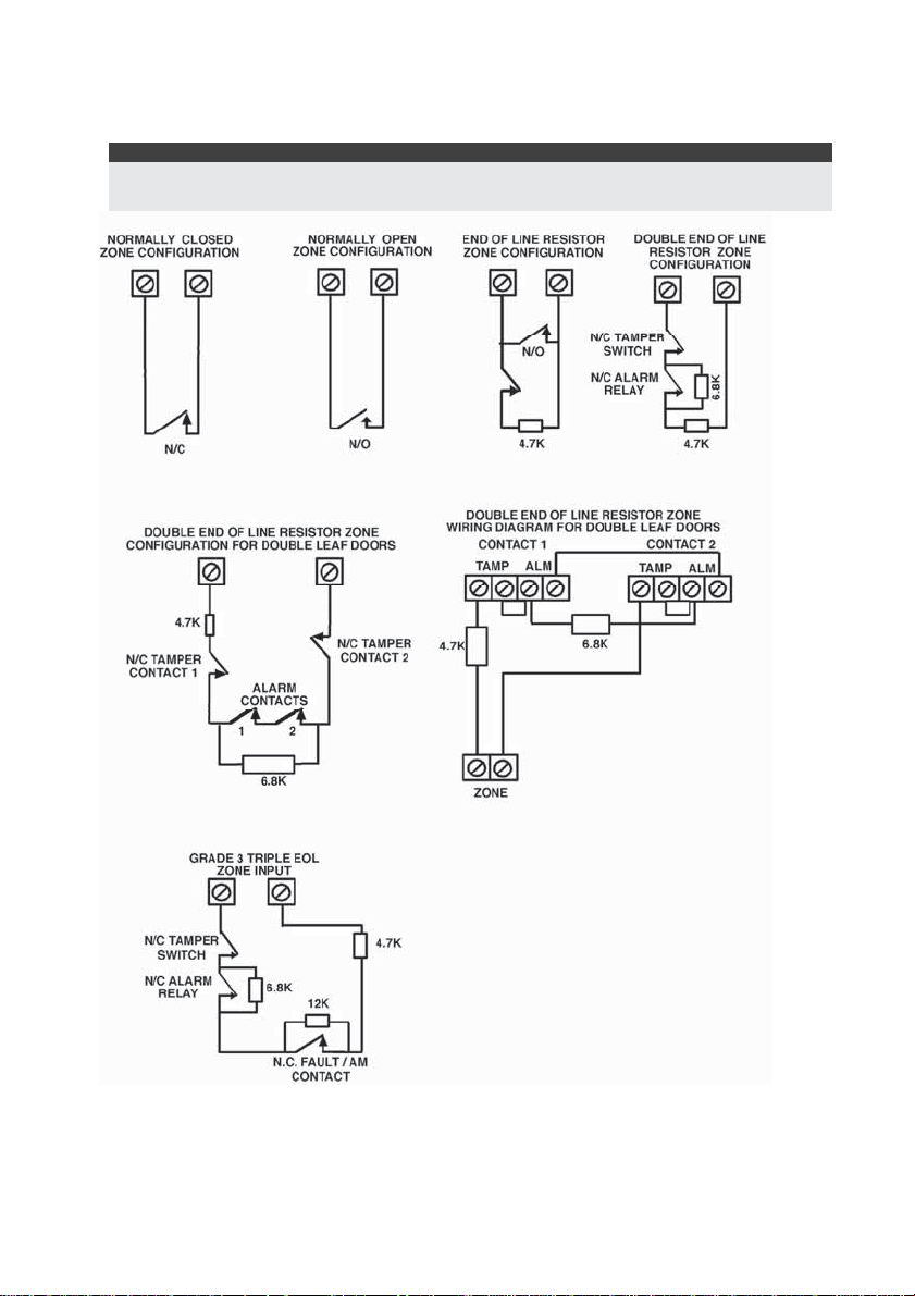
The following figure illustrates all types of termination with the new resistor values
that should be used for zone connections on the main board, new zone
expanders and relay inputs on iWISE Bus zones.
Important Note:
For all existing 8 and 16 hardwired zone expanders, the resistor values remain 2.2Kȍ
(resistors supplied with the product).
4 ProSYS Version 7.XX - Supplementary Instructions
Page 5

Bus Accessories
The information in this section describes new accessories that have been added
to the ProSYS Bus and modifications that have been implemented in parameters
under the Installer programming menu.
Touchscreen Keypad
There is a new 7" Touchscreen keypad with a slim and contemporary design. The
Touchscreen Keypad is compatible with any ProSYS version and is available with
or without a proximity reader.
Adding/deleting the Touchscreen keypad is identical to the procedure for the
adding/deleting of current ProSYS keypads.
Zone Expanders with TEOL Termination
There are two new wired zone expanders that support TEOL termination. See
TEOL explanation above.
When adding/deleting a zone expander there are two new types to choose from:
x G3Z08 (8 hardwired zone expander with TEOL termination)
x G3Z16 (16 hardwired zone expander with TEOL termination)
Note:
The current DEOL Zone Expander (ProSYS EZ8/EZ16/EZ8F) can still be used.
Bus Zone Expanders
A new wired Bus Zone Expander enables to expand the number of Bus zone
detectors in the ProSYS.
When adding/deleting a Bus Zone Expander select from the following options
depending on the amount of zones you want to use:
x BZE08 (8 Bus zone expander)
x BZE18 (16 Bus zone expander)
x BZE24 (24 Bus zone expander)
x BZE32 (32 Bus zone expander)
For detailed information refer to the instructions supplied with the Bus Zone
Expander.
Fast PSTN Modem - 2400 BPS
The Fast PSTN Modem enables PSTN communication at 2400 Bps between a
remote PC and the ProSYS security panel when programming the system using
the Upload/Download software.
Important:
Communication with the fast modem is supported by ProSYS Version 7 and above and by
Upload/Download software version 3.2.3.6 and above.
Adding the Fast PSTN Modem to ProSYS:
1. Access the Installer menu and select [7] Accessories > [1] Add Delete Module >
[9] More.. > [7] XMODEM.
Set the Type field to XModem.
ProSYS Version 7.XX - Supplementary Instructions 5
Page 6

2. Enable communication with the external fast modem:
Select [5] Dialer > [5] Control > [16] X. Modem Enable.
Set the parameter to Yes.
3. Ensure that the Upload/Download GSM parameter is set to No:
Select [5] Dialer > [5] Control > [15] Upload Download GSM Enable.
Verify that the parameter is set to No.
Note that when using the Upload/Download software in the Client Screen, the Fast
PSTN Modem option needs to be selected.
iWISE Grade 2 and 3 Bus Zone Detectors
There are four iWISE Bus zone detectors:
x iWISE DT Grade 2 15m (50') and 25m (82')
x iWISE QUAD Grade 2 15m (50')
x iWISE DT AM Grade 3 15m (50') and 25m (82')
x iWISE QUAD AM Grade 3 15m (50')
All iWISE Bus detectors include an additional on-board relay zone defined in the
software as an “input”. This zone can be used and assigned to any other relay
zone in the system.
Programming:
The iWISE Bus detectors are part of the Bus zones category. Therefore,
adding/deleting an iWISE Bus is identical to adding/deleting any Bus zone in the
system.
The iWISE Bus detectors can be assigned to a physical wired zone or to a virtual
zone or to a Bus Zone Expander.
Notes:
1. Up to 32 Bus detectors can be installed on the ProSYS main Bus.
2. Up to 128 Bus detectors can be assigned to the ProSYS using the Bus Zone Expanders.
For assigning the iWISE Bus detector using the Bus Zone Expander please refer to
the instructions supplied with the Bus Zone Expander.
Physical zone: Any zone on the ProSYS PCB (zones 1-8) or on a wired zone
expander (ZE08, ZE16, G3Z08, G3Z16, BZE08, BZE16, BZE24, BZE32).
Virtual zone: Any zone on a virtual zone expander defined as BZ08 or BZ16.
Notes:
Virtual Bus zones enable to expand your system zones without adding physical zone
expanders.
The virtual Bus Zone expander can be used only for Bus zone detectors. To add a virtual Bus
zone expander select type BZ08 or BZ16 when adding a zone expander.
1. Add/delete an iWISE Bus detector:
a. Access the Installer menu and select [7] Accessories > [1] Add Delete
Module > [9] More.. > [5] Bus Zone. The display will show:
Bus Zone:
(0:yy) TYPE=None
In the 0:yy designation, the 0 represents that the Bus detector is not
assigned to a Bus Zone Expander and the yy represents the Bus
detector ID number as set by the detector's DIP switches
6 ProSYS Version 7.XX - Supplementary Instructions
Page 7

b. Use the /
and
keys to position the cursor over
/
the Bus Zone ID number (yy designation) to which you want to assign
(or delete) a detector. Make sure that the detector’s physical ID
dipswitch setting is identical to the ID number you select during
programming.
c. Place the cursor on the TYPE field and use the
/ key to
select:
iDTG2 for an iWISE DT Grade 2 detector
iQDG2 for an iWISE QUAD Grade 2 detector
iDTG3 for an iWISE DT AM Grade 3 detector
iQDG3 for an iWISE QUAD AM Grade 3 detector
d. Press
/ to confirm.
e. Repeat the above steps for other Bus detectors.
2. Assign the iWISE Bus detectors to a Zone:
a. From the main Installer menu select [2] Zones > [1] One by One.
b. Select the zone number that you want to assign the Bus detector.
Note:
If you defined a virtual Bus Zone Expander, select a zone number from the virtual zones
(defined by the Bus Zone expander).
c. Define Partitions, Groups, Zone Type and Zone Sound.
d. In the Termination category, select [5] Bus Zone followed by
/ .
e. Select the Bus zone number to assign to the programmed zone. The
type field will be updated automatically when selecting the zone.
f. Press
/ . The loop response category is not applicable to a
Bus zone.
g. Press
/ , assign a label and press / .
3. If you want to use the extra relay zone input on the IWISE Bus detector:
a. Repeat steps a. – c. in step 2 above.
b. In the Termination category, select the relevant Bus Zone input
termination:
Bus Zone Input N/C
Bus Zone Input EOL
Bus Zone Input DEOL
Bus Zone Input N/O
Bus Zone Input TEOL
c. Press
/ . Select the Bus zone that the input zone belongs to.
The Type field will be updated automatically when selecting the zone.
d. Press
e. Press
/ . Define the loop response time.
/ , assign a label and press / .
4. Configure the iWISE Bus detector parameters:
a. From the main Installer menu select [2] Zones > [0] Miscellaneous >
[3] Bus Zone Parameters.
ProSYS Version 7.XX - Supplementary Instructions 7
Page 8

b. Select the zone that the Bus Zone was assigned to and press
/ .
c. Use the following tables to configure the parameters for the relevant
iWISE Bus detector.
Bus Zone Parameters: iWISE DT Grade 2
Quick Keys Parameter Default Range
[2][0][3][zz]
LEDS
On
[1]
Defines the LEDS operation mode.
[2][0][3][zz]
LEDS Options
[1] [1] to [2]
1) Off - Disables the LEDS operation.
2) On – Enables the LEDS operation.
[2][0][3][zz]
MW (Microwave) Range
Trimmer
[2]
Defines the microwave channel range.
[2][0][3][zz]
MW Range Options
[2] [1] to [7]
1) Minimum 2) 25% 3) 50% 4) 65% 5) 85% 6) Maximum 7) Trimmer
(MW is defined by the trimmer setting on the PCB)
[2][0][3][zz]
ACT
No
[3]
Defines the Anti-Cloak™ Technology (ACT) operation mode.
[2][0][3][zz]
ACT Options
[3] [1] to [2]
1) No - Disables the ACT mode.
2) Yes – Enables the ACT mode.
[2][0][3][zz]
Automatic Microwave Bypass
No
[4]
Defines whether the MW channel will be bypassed or not while the
detector identifies trouble in the MW channel.
[2][0][3][zz]
Automatic Microwave Bypass Options
[4] [1] to [2]
1) No - While detecting a problem in the MW channel it is not
bypassed. Alarm condition cannot be established until the MW
channel is fixed.
2) Yes - Switches the detector to operate only in PIR mode in case of
MW trouble.
[2][0][3][zz]
Green Line
Yes
[5]
A feature that follows environmental guidelines by avoiding surplus
emission. This feature defines the activation of the microwave
channel while the system is disarmed.
8 ProSYS Version 7.XX - Supplementary Instructions
Page 9

Bus Zone Parameters: iWISE DT Grade 2
Quick Keys Parameter Default Range
[2][0][3][zz]
Green Line Options
[5] [1] to [2]
1) No - Green Line feature is disabled. MW is constantly activated.
2) Yes – Green Line feature is activated.
[2][0][3][zz]
Self Test
Remote
[6]
Used to test the detection technologies. In the event of a failed test, a
Self Test Trouble is created.
[2][0][3][zz]
Remote (manual)
[6][1]
The remote self test is performed by the system when a user
manually selects the Diagnostics option from the Maintenance menu
via the ProSYS User Functions menu.
[2][0][3][zz]
Local (automatic)
[6][2]
Once an hour, the detector automatically checks that the detector’s
channels are functioning properly.
Bus Zone Parameters: iWISE DT AM Grade 3
Quick Keys Parameter Default Range
[2][0][3][zz]
LEDS
On
[1]
Defines the LEDS operation mode.
[2][0][3][zz]
LEDS Options
[1] [1] to [2]
1) Off - Disables the LEDS operation.
2) On – Enables the LEDS operation.
[2][0][3][zz]
MW (Microwave) Range
Trimmer
[2]
Defines the microwave channel range.
[2][0][3][zz]
MW Range Options
[2] [1] to [7]
1) Minimum 2) 25% 3) 50% 4) 65% 5) 85% 6) Maximum 7) Trimmer
(MW is defined by the trimmer setting on the PCB)
[2][0][3][zz]
ACT
No
[3]
Defines the Anti-Cloak™ Technology (ACT) operation mode.
[2][0][3][zz]
ACT Options
[3][1] to [2]
1) No - Disables the ACT mode.
2) Yes – Enables the ACT mode.
ProSYS Version 7.XX - Supplementary Instructions 9
Page 10

Bus Zone Parameters: iWISE DT AM Grade 3
Quick Keys Parameter Default Range
[2][0][3][zz]
Automatic Microwave Bypass
No
[4]
Defines whether the MW channel will be bypassed or not while the
detector identifies trouble in the MW channel.
[2][0][3][zz]
Automatic Microwave Bypass Options
[4][1] to [2]
1) No - While detecting a problem in the MW channel it is not
bypassed. Alarm condition cannot be established until the MW
channel is fixed.
2) Yes - Switches the detector to operate only in PIR mode in case of
MW trouble.
[2][0][3][zz]
Green Line
Yes
[5]
A feature that follows environmental guidelines by avoiding surplus
emission. This feature defines the activation of the microwave
channel while the system is disarmed.
[2][0][3][zz]
Green Line Options
[5] [1] to [2]
1) No - Green Line feature is disabled. MW is constantly activated.
2) Yes – Green Line feature is enabled.
[2][0][3][zz]
Anti-Mask
Enable
[6]
Defines the operation of Anti Masking detection.
[2][0][3][zz]
Anti-Mask Options
[6] [1] to [2]
1) Disable 2) Enabled and behaves according to the settings defined
in quick keys [2][0][3][zz][7] .
[2][0][3][zz]
Arm/Disarm
No
[7]
Defines the operation of the anti masking feature while the detector
is armed or disarmed.
[2][0][3][zz]
Arm/Disarm Options
[7] [1]
1) No – When detector is armed or disarmed Anti-mask behaves
according to the settings defined in quick keys [2][0][3][zz][6]
2) Yes –When detector is armed Anti-mask is disabled. When
detector is disarmed Anti-mask behaves according to the settings
defined in quick keys [2][0][3][zz][6]
[2][0][3][zz]
Self Test
Remote
[8]
Used to test the detection technologies. In the event of a failed test, a
Self Test Trouble is created.
10 ProSYS Version 7.XX - Supplementary Instructions
Page 11

Bus Zone Parameters: iWISE DT AM Grade 3
Quick Keys Parameter Default Range
[2][0][3][zz]
Remote (manual)
[8] [1]
The remote self test is performed by the system when a user
manually selects the Diagnostics option from the Maintenance menu
via the ProSYS User Functions menu.
[2][0][3][zz]
Local (automatic)
[8] [2]
Once an hour, the detector automatically checks that the detector’s
channels are functioning properly.
Bus Zone Parameters: iWISE QUAD Grade 2
Quick Keys Parameter Default Range
[2][0][3][zz]
LEDS
On
[1]
Defines the LEDS operation mode.
[2][0][3][zz]
LEDS Options
[1] [1] to [2]
1) Off - Disables the LEDS operation.
2) On – Enables the LEDS operation.
[2][0][3][zz]
Sensitivity
Normal
[2]
Defines the sensitivity of the detector (PIR).
[2][0][3][zz]
Sensitivity Options
[2] [1]to[2]
1) Low 2) High
[2][0][3][zz]
Self Test
Remote
[3]
Used to test the detection technologies. In the event of a failed test, a
Self Test Trouble is created.
[2][0][3][zz]
Remote (manual)
[3][1]
The remote self test is performed by the system when a user
manually selects the Diagnostics option from the Maintenance menu
via the ProSYS User Functions menu.
[2][0][3][zz]
Local (automatic)
[3][2]
Once an hour, the detector automatically checks that the it's
channels are functioning properly.
ProSYS Version 7.XX - Supplementary Instructions 11
Page 12

Bus Zone Parameters: iWISE QUAD AM Grade 3
Quick Keys Parameter Default Range
[2][0][3][zz]
LEDS
On
[1]
Defines the LEDS operation mode.
[2][0][3][zz]
LEDS Options
[1] [1] to [2]
1) Off - Disables the LEDS operation.
2) On – Enables the LEDS operation.
[2][0][3][zz]
Sensitivity
Normal
[2]
Defines the sensitivity of the detector (PIR).
[2][0][3][zz]
Sensitivity Options
[2] [1]to[2]
1) Low 2) High
[2][0][3][zz]
Anti-Mask
Enable
[3]
Defines the operation of Anti Masking detection.
[2][0][3][zz]
Anti-Mask Options
[3] [1]to[2]
1) Disable 2) Enable and behaves according to the settings defined
in quick keys [2][0][3][zz][4] .
[2][0][3][zz]
Arm/Disarm
No
[4]
Defines the operation of the anti masking feature while the detector
is armed or disarmed.
[2][0][3][zz]
Arm/Disarm Options
[4][1]
1) No – When detector is armed or disarmed Anti-mask behaves
according to the settings defined in quick keys [2][0][3][zz][3]
2) Yes – When detector is armed Anti-mask is disabled. When
detector is disarmed Anti-mask behaves according to the settings
defined in quick keys [2][0][3][zz][3].
[2][0][3][zz]
Self Test
Remote
[5]
Used to test the detection technologies. In the event of a failed test, a
Self Test Trouble is created.
[2][0][3][zz]
Remote (manual)
[5][1]
The remote self test is performed by the system when a user
manually selects the Diagnostics option from the Maintenance menu
via the ProSYS User Functions menu.
[2][0][3][zz]
Local (automatic)
[5][2]
Once an hour, the detector automatically checks that the detector’s
channels are functioning properly.
12 ProSYS Version 7.XX - Supplementary Instructions
Page 13

Bus Detector Naming Conventions
The following table contains the names of the various Bus detectors and their
corresponding Installer programming menu codes under the Type field, when
adding a new Bus zone to the system.
Bus Detector TYPE Field Option
in Previous Versions
TYPE Field Option
in Version 7 and above
WatchOUT DT ODT15 ODT15
WatchOUT PIR OPR12 OPR12
Industrial LuNAR LUNR Cannot be selected,
Replaced by Industrial
LuNAR Grade 3.
Industrial LuNAR Grade 3 LUNG3 ILun3
WatchIN IDT25 WatIN
iWISE DT G2 Bus 15m,
25m
N/A iDTG2
iWISE QUAD G2 Bus N/A iQDG2
iWISE DT G3 Bus 15m,
25m
iWISE QUAD G3 Bus N/A iQDG3
N/A iDTG3
New Firmware Capabilities
The information in this section describes new capabilities in the ProSYS firmware
and new parameters under the Installer programming menu.
Tamper Test during Exit Programming
When exiting the Installer Programming menu, ProSYS will check if there are any
existing tamper faults in the system. A list of these tamper faults will appear. The
installer can select whether to confirm exiting the programming mode with a
tamper condition and by this a tamper alarm can occur or fix the tamper faults.
WatchOUT Proximity Anti Mask in WatchOUT extreme
WatchOUT DT version B (P/N RK325DT00xxB) has a new proximity anti masking
capability in addition to its improved IR anti masking capability.
When the WatchOUT DT is installed as a Bus zone, in order to enable Proximity
Anti-Mask the following parameters must be programmed:
Zones Miscellaneous: Bus Zone - WatchOUT
Quick Keys Parameter Default Range
[2][0][3][zz]
Prox Anti Mask
Enable
[8]
Defines the operation of proximity anti masking detection.
[1] Disable [2] Enable
ProSYS Version 7.XX - Supplementary Instructions 13
Page 14

System: Controls
Quick Keys Parameter Default Range
[1][2][37] Prox AM=Tamper
No
Used to determine the operation of the proximity anti masking
detection.
Yes: Proximity anti mask detection will activate the tamper alarm.
No: Proximity anti mask detection will be regarded as a trouble
event.
Note that this parameter is new and replaces the VBR=Tamper
parameter that once used the same quick key sequence.
Note that Proximity AM operates for approximately 2.2 seconds
when the detector is approached in close proximity.
Utility Output Operation Using Proximity Tag
A Utility Output that is defined as “Follow Code” can now also be activated when
a proximity tag is presented to a proximity key reader or a proximity keypad.
ACM Supported in ProSYS 16 and ProSYS 40
The Advanced Communication Module (ACM) that was previously supported only
in ProSYS 128 is now supported in the ProSYS 16 and ProSYS 40 models.
New SMTP User and Password Parameters
Quick Keys Parameter Default Range
[5][7][5][6] SMTP User Name – New Parameter
21 characters
This is a new ACM E-Mail parameter that defines the user name that
the SMTP server requires for authentication when defined as such by
the IT department.
[5][7][5][7] SMTP Password – New Parameter
21 characters
This is a new ACM E-Mail parameter that defines the password that
the SMTP server requires for authentication when defined as such by
the IT department.
New Feature - MS Polling by IP/GPRS
Quick Keys Parameter Default Range
[5][0][4] MS Polling by IP network
IP Primary
This parameter checks connectivity between RISCO Group's IP/GSM
Receiver software and the ProSYS panel by sending polling signals
from the ProSYS ACM via the IP channel. Ensure that the IP channel
has been configured properly in the IP/GSM Receiver software.
The information regarding which MS is to be used to perform the
polling is defined according to the MS report split for “urgent events”.
The time intervals for performing the polling with each MS is defined
under the IP Primary, Secondary and Backup parameters.
14 ProSYS Version 7.XX - Supplementary Instructions
Page 15

Quick Keys Parameter Default Range
The following table describes how the three MSs use the primary,
secondary and backup time intervals in the various MS report split
options.
[5][0][4][1]
MS report
split for
urgent
MS #1
Polling
State
MS #2
Polling
State
MS #3
Polling
State
events
DO NOT
N/A N/A N/A
CALL
CALL 1ST Primary N/A N/A
CALL 2ND N/A Primary N/A
CALL 3RD N/A N/A Primary
CALL ALL Primary Primary Primary
1ST BKUP
ND
2
Primary If (MS#1 is OK)
Secondary
N/A
Else (MS#1
Failed)
Backup
1ST BK
ND3RD
2
Primary If (MS#1 is OK)
Secondary
Else (MS#1
Failed)
Backup
If (MS#2 is OK)
Secondary
Else (MS#2
Failed)
Backup
1ST BK 3
CALL2
Primary Primary If (MS#1 is OK)
Secondary
Else (MS#1
Failed)
Backup
2ND BK 3
CALL1
Primary Primary If (MS#2 is OK)
Secondary
Else (MS#2
Failed)
Backup
Important note:
The installer must manually enter the report code value of 87 under the Report
Codes programming menu using quick keys [6][8][0][4]. This value represents
SIA code ZZ and Contact ID code 999 that are used to validate the report
process.
IP Primary
00003 (x10
0-65535 sec
sec)
Defines the polling interval through the primary channel. When using
the default time, a polling message is sent every 30 seconds.
When the IP Primary polling time is defined as 0, no polling message
is sent to the MS (when the MS channel is in the Primary polling
mode).
ProSYS Version 7.XX - Supplementary Instructions 15
Page 16

Quick Keys Parameter Default Range
[5][0][4][2] IP Secondary
00360 (x10
0-65535 sec
sec)
Defines the polling interval through the secondary channel. When
using the default time, a polling message is sent every 3600 seconds
(1 hour).
When the IP Secondary polling time is defined as 0, no polling
message is sent to the MS (when the MS channel is in the Secondary
polling mode).
[5][0][4][3] IP Backup
00003 (x10
0-65535 sec
sec)
Defines the polling interval through the backup channel. When using
the default time, a polling message is sent every 30 seconds.
When the IP Backup polling time is defined as 0, no polling message
is sent to the MS (when the MS channel is in the Backup polling
mode).
Quick Keys Parameter Default Range
[8][3][1][5]
MS Polling through GPRS
GPRS Primary
[4]
This parameter checks connectivity between RISCO Group's IP/GSM
Receiver software and the ProSYS panel by sending polling signals
from the ProSYS GSM via the GPRS
channel. Ensure that the GPRS
channel has been configured properly in the IP/GSM Receiver
software.
For additional information, refer to the above description that appears
for MS Polling through IP network.
Note:
The only difference from the above explanation (MS Polling by IP) is that the
default time intervals for Primary and Backup in MS Polling through GPRS are
defined as 9 (90 seconds).
MS Polling example:
When selecting MS#1 IP(ACM), MS#2 GPRS (GSM) and split report option 1st
BKUP 2ND (using the default primary, secondary and backup values), the report
process will be as follows:
In a normal state:
Polling through the IP network using the ACM will occur every 30 seconds
according to the primary time interval.
Polling through the GPRS network using the GSM module will occur every 3600
seconds (1 hour) according to secondary time interval.
When communication to MS#1 (ACM) fails, polling through the GPRS network
occurs every 90 seconds according to the backup time interval. When
communication returns to MS#1, polling through the GPRS network reverts back
to the secondary time interval and occurs every 3600 seconds (1 hour).
© RISCO Group 06/09 5IN1181 C
16 ProSYS Version 7.XX - Supplementary Instructions
 Loading...