

Page 1

PPrrooSSYYSS –– AACCMM
((MMooddeellss:: AACCMM AAAA0011,, AACCMM AABB0011)
FFoorr uussee wwiitthh RRIISSCCOO GGrroouupp''ss SSeeccuurriittyy
SSyysstteemms
s
)
Page 2

2 Advanced Communication Module
Page 3

Table of Contents
INTRODUCTION........................................................................................4
ACM FEATURES........................................................................................5
COMPATIBILITY........................................................................................5
MOUNTING & CONNECTIONS..................................................................6
TERMINAL BLOCK WIRING......................................................................8
JUMPER SETTINGS ..................................................................................8
LED INDICATION.......................................................................................9
PROGRAMMING THE ACM - GENERAL .................................................11
A
DDING DELETING THE ACM..................................................................11
D
EFINING MS CONNECTION TYPE...........................................................11
D
EFINING ACM PARAMETERS ................................................................13
D
EFINING THE ACM CONTROL PARAMETERS ...........................................15
EFINING THE NETWORK CONTROL PARAMETERS ....................................16
D
EFINING ACM SPECIAL FUNCTIONS ......................................................16
D
V
IEWING ACM VERSION AND PARAMETERS .............................................16
E-MAIL
REPORT BY THE ACM...............................................................17
E
VENTS REPORT OVER IP .....................................................................18
G
ETTING ACM IP ADDRESS...................................................................18
APPENDIX - A: IP ADDRESS TABLE (ACM CHANNEL)........................19
APPENDIX - B: PORT TABLE..................................................................19
APPENDIX - C: COMMON TERMS AND DEFINITIONS..........................20
TECHNICAL SPECIFICATION.................................................................22
ORDERING INFORMATION.....................................................................22
CUSTOMER INFORMATION ...................................................................22
Advanced Communication Module 3
Page 4
Introduction
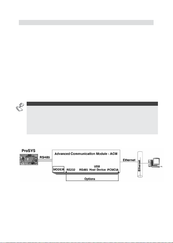
The ACM (Advanced Communication Module) is a communication
accessory for the ProSYS control panel, for enhancing its hardware and
software connectivity. It enables TCP/IP Ethernet connectivity and
enables usage of existing LAN and WAN infrastructures for the transfer of
security data. The ACM offers full functionality of the ProSYS over
TCP/IP, and provides Ethernet and Fast Modem Interface.
ACM Encryption is of the SSL/TLS type. The module can be
simultaneously accessed by multiple clients and seamlessly connects to
Upload/Download software, thus enabling remote access and monitoring.
ACM versions include:
Ê ACM Basic - includes RS485 and Ethernet interfaces
Ê ACM Basic + Modem - includes Ethernet interfaces plus fast modem
interface
Ê ACM Full future configuration with interfaces is shown in Figure 1.
NOTES:
1. The programming options described in this manual refer to both Universal and UK
ProSYS versions. The UK differences in programming locations are indicated
below the Universal programming options.
2. The ACM AB01 is UL approved only as supplementary and cannot be relied upon
for MS communication , hence the DACT(PSTN) must be the primary
communicator to MS.
Figure 1: ACM Interfaces - Full Configuration
4 Advanced Communication Module
Page 5

ACM Features
i Provides IP connectivity over networks supporting the TCP/IP
protocol (LAN and WAN).
i Fully supervised accessory of the ProSYS
i Secure communication with full SSL stack, 256 bit encryption,
cipher key changed frequently making it difficult to break the code
i IP Receiver software available for compatibility with Monitoring
Station applications
i Compatible with 10BaseT and 100BaseT networks
i Supports simultaneous multiple channel Ethernet communication
i Selected events may be reported to two different email addresses.
Security Manager can receive security events, while installer
receives technical indications only.
i Embedded web server with application links into the ProSYS control
panel
i Supports dynamic network addressing (DHCP)
i Module firmware is remotely upgradeable when a new version is
released
i Customizable according to project requirements
i Optional fast modem interface 56-kbps
Compatibility
The ACM module is compatible with the ProSYS 40 (UK version only) and
ProSYS 128 (All versions), software version 4.xx and above.
The ACM is compatible with RISCO Group's Upload/Download Software
Version 1.8 and above.
Advanced Communication Module 5
Page 6

Mounting & Connections
The ACM may be mounted onto the ProSYS main board using the
provided plastic spacers or in a special accessory box (P/N:
RP128B300UKA).
NOTES:
1. Handle the ACM module with care when installing it.
2. When attaching an ACM box to the wall, it is recommended to use Ø4.2mm, 32mm
length screws (DIN 7981 4.2X32 ZP).
3. In order to meet EMC requirements, it is recommended that when the ACM is
installed in a special accessory box use a ferrite bead manufactured by Fair-Rite
p/n 2643626502 with one turn at the 4-wire cable Bus close to the connector
inside the metal box.
4. The ACM is only UL listed for installation on the main ProSYS boa rd.
To connect the ACM to the ProSYS, perform the following steps:
IMPORTANT:
1. Disconnect all power sources from the ProSYS panel prior to servicing the ACM or
connecting it to the panel BUS!
2. Before connecting the ACM, calculate and check that the power drawn by the ACM,
together with all accessories connected to the ProSYS, is within the power supply
current range! Add a power supply module if required.
UL NOTE:
For UL installation only UL listed burglar alarm power supply can be used.
1. Mount the ProSYS main board inside the BOX as described in the
Installer manual 5IN128IM.
2. Attach the 4 plastic spacers using the provided plastic screws to the
ProSYS main holes shown in Figure 2.
3. Connect 2 plastic support spacers to the ACM board (using plastic
screws) as shown in Figure 2.
4. Align the ACM mounting holes with the spacers on the ProSYS panel
and snap into place.
5. Connect the provided 4-wire cable from the ACM BUS connector to
the ProSYS BUS connector.
6. Connect the ACM to the Ethernet by plugging an appropriate
Ethernet cable plug into the RG-45 connector on the ACM (see
Figure 2).
NOTES:
In order to meet EMC requirements, it is recommended to use a ferrite bead
manufactured by Fair-Rite p/n 0446167281 with one turn at the Ethernet cable close to
the connector inside the metal box.
6 Advanced Communication Module
Page 7
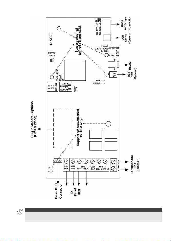
Figure 2: ACM Layout with Spacers
UL NOTE:
UL approved unit ACM AB01 does not include any of the optional items which appear in
figure 2.
Advanced Communication Module 7
Page 8
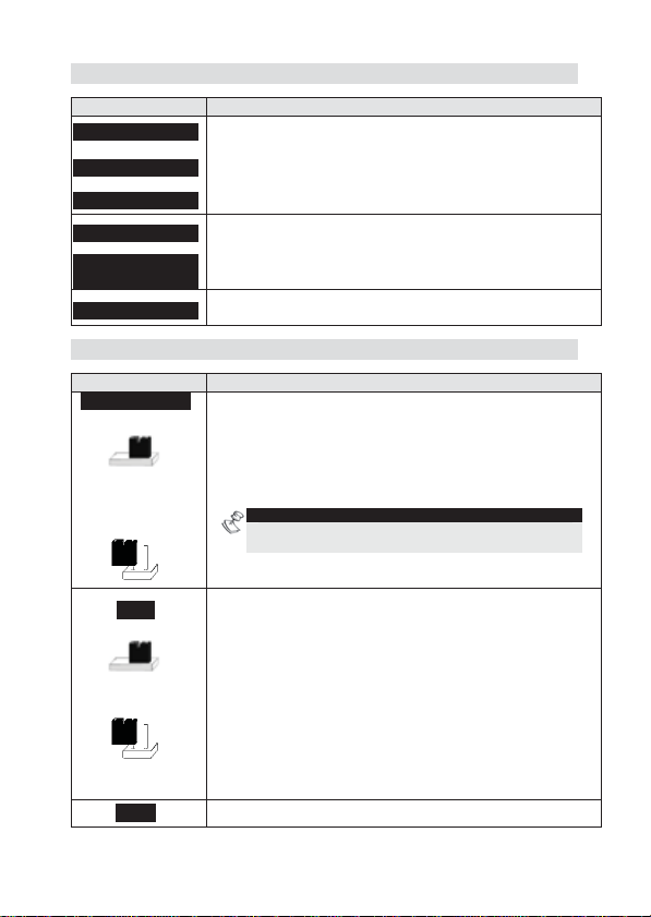
Terminal Block Wiring
Terminal Description
AUX RED
COM BLK
BUS YEL GRN
COM BLK
BUS 2 YEL2
GRN2
TIP, RING
Used to connect the ACM to the ProSYS Panel board
(the terminals are connected in parallel to the panel
BUS connector).
Provision for optional functionality
Used for PSTN telephone line connection (for ACM
version that includes the modem option).
Jumper Settings
Jumper Description
STAND AL ONE
DFLT
CFG2 Provision for optional functionality
Used to enable a local U/D connection to the ProSYS
using a local PC, while the ACM is connected to the
BUS.
2 pins configuration: The ACM U/D channel is
disabled, and a local U/D connection to the ProSYS
Bus is enabled.
NOTE:
Sending information from the panel via the ACM is
functioning normally.
1 pin (default): Local U/D connection to the ProSYS
Bus is disabled, and the ACM channel is enabled.
Used to restore the default software provided by the
manufacturer (e.g. when remote software upgrade
fails).
2 pins configuration: Enables restoring of the default
manufacturer’s software.
To restore the ACM to the default manufacturers
software:
1) Disconnect power from the ACM
2) Place the DFLT jumper on its 2 pins.
3) Reconnect the power to the ACM.
1 pin (default): Restoring of the default
manufacturer’s software is not enabled.
8 Advanced Communication Module
Page 9

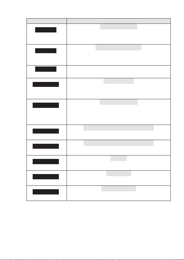
LED Indication
LED Description
LINK
(Yellow)
ACTIV
(Green)
10/100
(Green)
SERIAL 1
(optional)
(Green)
SERIAL 2
(optional)
(Green)
GOOD LINK
(USB) - optional
(Green)
POWER
(Red)
RUN
(Red)
MODEM RX
(Green)
Indicates appropriate communication between the
ACM and the Ethernet network.
ON: Ethernet communication OK.
OFF: Ethernet connection is not working (check cable).
Indicates either active or non-active Ethernet
communication.
ON: Data packets are being transmitted or received via
the Ethernet.
OFF: No data packets are being transmitted or
received via the Ethernet.
Indicates data transmission speed over the Ethernet
(the ACM automatically detects the speed).
ON: 100 Mbps
OFF: 10 Mbps
Indicates ACM communication with a device via the
optional RS232 serial port 1.
Indicates ACM communication with a device via the
optional RS232 serial port 2.
Indicates communication between the ACM and a
device connected to the optional USB port.
Indicates communication status between the ACM and
the ProSYS main panel via the RS 485 BUS.
ON: Normal communication with the ProSYS panel
OFF: No communication with the ProSYS panel
Slow flashing: When BUS communication is
interrupted, during ProSYS programming, or if the
ACM has not been programmed correctly during
installation.
Indicates the CPU operation
Indicates data reception via the ACM’s optional
modem.
ON: Data reception is in process.
OFF: Data reception is not in process.
Advanced Communication Module 9
Page 10

LED Description
MODEM TX
(Red)
STAND AL ONE
(Yellow)
PCMCIA IN
(optional)
(Green)
PCMCIA READ
(optional)
(Yellow)
COMM 485
(optional)
(Red)
10 Advanced Communication Module
Indicates data transmission via the ACM’s optional
modem.
ON: Data transmission is in process.
OFF: Data transmission is not in process.
Indicates either enabled or disabled local U/D
connection to the ProSYS.
ON: Local U/D is enabled and ACM U/D channel is
disabled.
OFF: Local U/D is disabled and ACM U/D channel is
enabled.
Indicates presence of PCMCIA card.
Indicates communication between the ACM and
PCMCIA card.
Indicates communication status via an optional
additional RS485 port.
Page 11

Programming the ACM - General
The ACM Module is programmed in a similar manner to all ProSYS
accessories, via the LCD keypad or via the UD Software, locally or
remotely.
The following information refers to ACM programming features added for
ACM functionality. We recommend reading and fully understanding the
ProSYS Installation and User Manuals, before programming the ACM.
NOTE:
The term “Provision for” in the fo llowing programming instructions, refers to optional
additional functionality!
The quick keys and programming locations for the ProSYS UK version are marked in
Italic text
Adding Deleting the ACM
To add/delete the ACM module, perform the following steps:
1. From the ProSYS installer menu, enter the ADD/Delete option
(Quick Key [7][1]).
2. Press [9][3] to access the ACM module option.
3. Use the
or ACM1 (ACM installed).
4. Press
Defining MS Connection Type
Connection between the ProSYS panel and the monitoring station
(MS) is configured via the DIALER (Digicom) Menu.
From the ProSYS installer menu, access the Dialer menu [5].
1. Press [1] to access the Link Up sub-menu.
2. Use the quick key combinations described in the table below to
access your desired option and configure your system as desired.
Quick Key Parameter
[5][1][1]
[5][1][1][1]
NOTE:
3 linkups are available.
/ / key to select either NONE (no ACM)
/ / to confirm your selection.
MS LINK UP
Defines the link up parameters between the
monitoring station receiver and the ProSYS panel.
MS 1 LINK UP
Defines the link up parameters used for the first
monitoring station.
Advanced Communication Module 11
Page 12

Quick Key Parameter
[5][1][1][1][1]
[5][1][1][1][2]
[5][1][1][1][3]
[5][1][1][1][4]
[5][1][2]
The ProSYS will report the monitoring station over
the voice channel (PSTN or GSM if connected).
Define the MS (Monitoring Station) telephone
number. Up to 32 digits may be typed in to define
the CS telephone numbers, including dialing
prefixes and area codes or special letters. For
more information refer to the ProSYS Installer
manual.
The ProSYS will report the MS over the TCP/IP
using the ACM.
Define the MS IP address and port that identifies
the receiver on the network.
Note: RISCO IP/GSM receiver has to be at the
MS site
Default: 192.168.001.010
The ProSYS will report the MS via SMS using
RISCO's GSM/GPRS module. Define the MS GSM
phone number.
Note: RISCO IP/GSM receiver has to be at the MS
site.
Default: 03010
The ProSYS will report the MS via the GPRS
network using the GSM/GPRS module. Define the
IP and Port address of the IP/GSM receiver on the
network.
Note: RISCO IP/GSM receiver has to be at the
MS site
Default IP:192.168.001.010
Default Port: 03010
The phone numbers to which the alarm company’s
computer, equipped with the Upload/Download
software, is connected.
PSTN/VOICE
IP
SMS
GPRS
U/D PHONES
12 Advanced Communication Module
Page 13

Defining ACM Parameters
From the Dialer menu [5] press [0][2] to enter ACM Parameters Menu.
(ProSYS UK: [8][1][1])
Quick Key Parameter
[5][0][2][1]
UK: [8][1][1][1]
[5][0][2][2]
UK: [8][1][1][4]
[5][0][2][3]
UK: [8][1][1][5]
[5][0][2][4]
UK: [8][1][1][6]
[5][0][2][5]
UK: [8][1][1][7]
[5][0][2][6]
UK: [8][1][1][2]
[5][0][2][7]
UK: [8][1][1][3]
[5][0][2][8]-[9]
UK: [8][1][1][8]-[9]
The static IP address that identifies the ACM
module on the network.
Default: 192.168.001.100
The port address of the ACM U/D application.
Default: 03000
The port address of the ACM AUX. protocol 1. The
ACM AUX 1 protocol supports the Modbus TCP/IP
protocol by default.
Default: 00502
Provision for optional functionality
Provision for optional functionality
The definition of the network portion of the IP
address. This location must be configured that all
IP addresses up to and including the local gateway
are allowed.
Default: 255.255.255.0
The IP address of the local Gateway, which
enables communication settings to other LAN
segments. This address is the IP address of the
router connected to the same LAN segment as the
ACM module.
Default: 192.168.001.254
Remote upgrading allows remote downloading of
upgraded software over the network. The new
upgraded software is stored in a specific IP
address on the network. Once the ACM is
informed of the new software, it refers to the IP
address to download the new software.
ACM IP ADDRESS
ACM U/D PORT
ACM AUX 1 PORT
ACM AUX 2 PORT
ACM AUX 3 PORT
SUBNET IP MASK
GATEWAY IP ADDR
REMOTE UPGRADE of ACM
Advanced Communication Module 13
Page 14
Quick Key Parameter
[5][0][2][8]
UK: [8][1][1][8]
[5][0][2][9]
UK: [8][1][1][9]
[5][0][2][0]
UK: [8][1][1][0]
[5][0][2][0][1]
UK: [8][1][1][0][1]
[5][0][2][0][2]
UK: [8][1][1][0][2]
[5][0][2][0][3]
UK: [8][1][1][0][3]
[5][0][2][0][4]
UK: [8][1][1][0][4]
[5][0][2][0][5]
UK: [8][1][1][0][5]
[5][0][2][0][6]
UK: [8][1][1][0][6]
[5][0][2][0][7]
UK: [8][1][1][0][7]
The IP address that the ACM turns to, for
downloading the upgraded software.
Default:192.168.100.001
The port address that the ACM turns to, during the
process of software upgrading.
Default: 00080
More …
The IP address from which a connection to the
ACM can be established via the U/D software.
Default: 0.0.0.0
A text name used to identify the ACM module over
the network.
Default: acm
Range: 16 characters of any type
Provision for optional functionality
Provision for optional functionality
Provision for optional functionality
Provision for optional functionality
Provision for optional functionality
S.W UPDATE IP
S.W UPDATE PORT
U/D IP MASK
ACM NET NAME
DOMAIN NAME SYSTEM 1# IP
DOMAIN NAME SYSTEM 2# IP
NTP IP
NTP PORT
NTP UPD TIME
14 Advanced Communication Module
Page 15

Defining the ACM Control Parameters
From the Dialer menu [5], press [0][3] to enter the ACM Control
parameters Menu .
Quick Key Parameter
[5][0][3][1]
UK: [8][1][2][1]
[5][0][3][1][1]
UK: [8][1][2][1][1]
[5][0][3][1][2]
UK: [8][1][2][1][2]
[5][0][3][2]
UK: [8][1][2][2]
[5][0][3][3]
UK: [8][1][2][3]
[5][0][3][4]
UK: [8][1][2][4]
[5][0][3][5]
UK: [8][1][2][5]
Defines the ACM parameters configuration.
Provision for optional functionality
Defines whether the IP address, which the ACM
refers to, is static or dynamic
YES: The ACM refers to an IP address provided
by the DHCP
NO: The ACM refers to the ACM static IP Address
defined by quick key [5][0][2][1].
Default: NO
Defines the authorization type when using the U/D
software application over the Ethernet network;
i Disabled
i Full Control (ENABLED)
Default: Full Control
Defines the authorization type when using the
received application by the ACM auxiliary 1
protocol (Modbus).
i Disabled
i Full Control (ENABLED)
Default: Disabled
Provision for optional functionality
ACM CONFIGURATION
CLIENT ATN
DHCP IP
.
ACM U/D CONFIGURATION
ACM AUX1 CONFIGURATION
ACM AUX2 CONFIGURATION
ACM AUX3 CONFIGURATION
Advanced Communication Module 15
Page 16

Defining the Network Control Parameters
From the Dialer menu [5], press [0][4] to enter the Network Control
parameters Menu.
Quick Key Parameter
[5][0][4]
UK: [8][1][4]
This option contains parameters that specify
counters for the ACM to establish a connection
MS KEEP ALIVE
with the network.
Defining ACM Special Functions
From the Dialer menu [5], press [0][4] to enter the Network Control
parameters Menu.
Quick Key Parameter
[5][0][5]
UK: [8][1][5]
The ACM Special function menu enables you to
perform special operations of the ACM. This option
is applicable for ACM with dedicated features that
are customized per project (e.g. performing remote
upgrade of the ACM).
A confirmation beep is heard in the keypad,
indicating that the command was successfully sent
to the ACM, followed by the following message:
“SPECIAL MESSAGE ACTIVATED”.
Default: 001
Range: 001-255
Viewing ACM Version and Parameters
Quick Key Parameter
[5][0][6]
UK: [8][1][6]
This menu is used to view the ACM hardware and
software configurations.
The information includes 4 parameters as follows:
i ACM MAC Address
i ACM Software Version
i ACM Hardware Version
i ACM Project Number
If a communication trouble with the ACM occurs,
the “COMMUNICATION TROUBLE” message
appears and 3 beeps are heard from the keypad.
16 Advanced Communication Module
Page 17

E-MAIL Report by the ACM
The ProSYS can send follow me events reports by Email using the
ACM or the GSM/GPRS module. .
To send report by the ACM select the Follow Me type ACM Mail option.
Quick Key Parameter
[5][7][4][FM
number][1][4]
To enable event reporting using the ACM, the following parameters
should be defined.
Quick Key Parameter
[5][7][5][1]
UK: [8][1][3][1]
[5][7][5][2]
UK: [8][1][3][2]
[5][7][5][3]
UK: [8][1][3][3]
[5][7][5][4]
UK: [8][1][3][4]
[5][7][5][5]
UK: [8][1][3][5]
Follow me report will be established by Email using
the ACM. The email address is defined in the user
menu (quick key [2][7][Code][FM defined as ACM
mail]
NOTE:
Only Follow Me 1 and 2 can be defined to send Email
report by using the ACM.
The IP address of the ACM mail server.
Default: 192.168.001.253
The port address of the ACM SMTP mail server
port, used to send messages.
Default: 00025
The port address of the ACM POP3 mail server
port, used to retrieve e-mails.
Default: 00110
The ACM email address prefix; 16 characters are
used to define the ACM email prefix (for example
in the ACM@riscogroup.coml e-mail address, the
prefix name is “ACM”).
Default: acm
The ACM email address domain name, which
identifies the web server of the ACM. For example,
in the email address ACM@riscogroup.com, the
domain name is riscogroup.com.
NOTE:
Do not enter the @ sign.
Default: YourCompany.com
ACM MAIL
MAIL IP ADDRESS
MAIL SMTP PORT
MAIL POP3 PORT
E-MAIL PREFIX
E-MAIL Domain
Advanced Communication Module 17
Page 18

Events Report Over IP
In addition to local events printing (using a local printer connected to
the ProSYS), the ACM will enable storing of unlimited amount of
events over Ethernet resources, which can be used for backup and
analysis. (Not applicable for the ProSYS UK version).
Quick Key Parameter
[5][7][6][1]
[5][7][6][2]
[5][7][6][3]
Getting ACM IP Address
In some installations the ACM IP address might be configured to be
dynamic (see quick key [4][0][3] for DHCP IP address). In this case the
host server will assign the IP address.
Sometimes it might be needed to get the IP address, from someone on
the premises in order to maintain a proper operation of the ACM over
the network.
To get the ACM IP address:
From the ProSYS user menu enter Maintenance by pressing [*][4]
Enter the Grand Master Code followed by the
Press [0][3] for the option “GET ACM IP”.
Press
appears on the LCD.
/ / to confirm; the desired ACM IP address
Provision for optional functionality
Provision for optional functionality
Provision for optional functionality
ENABLE
E-LOG IP ADDRESS
E-LOG IP PORT
/ / .
18 Advanced Communication Module
Page 19

Appendix - A: IP Address Table (ACM Channel)
Description Default
MS x IP Address
ACM IP Address
SUBNET IP MASK
Gateway IP
Software update IP
Mail IP Address
DNS#1 SERVER IP
DNS#2 SERVER IP
NTP SERVER IP
U/D IP MASK
192.168.001.010 [5][1][1][x][2] [5][1][1][x][2]
192.168.001.100 [5][0][2][1] [8][1][1][1]
255.255.255.000 [5][0][2][6] [8][1][1][2]
192.168.001.254 [5][0][2][7] [8][1][1][3]
192.168.100.001 [5][0][2][8] [8][1][1][8]
192.168.001.253 [5][7][5][1] [8][1][3][1]
192.168.100.251 [5][0][2][0][3] [8][1][1][0][3]
192.168.100.252 [5][0][2][0][4] [8][1][1][1][4]
192.168.000.060 [5][0][2][0][5] [8][1][1][1][5]
000.000.000.000 [5][0][2][0][1] [8][1][1][0][1]
Programming
Location to
Configure
Appendix - B: Port Table
Description Default
MS x Port
ACM U/D Port
ACM AUX 1 Port
ACM AUX2 PORT
ACM AUX3 PORT
Software Update IP
Mail SMTP Port
Mail POP3 Port
NTP SERVER PORT
03010
03000 [5][0][2][2]
00502 [5][0][2][3]
03001 [5][0][2][4]
03002 [5][0][2][5]
00080 [5][0][2][9]
00025 [5][7][5][2]
00110 [5][7][5][3]
00123 [5][0][2][0][6]
Programming
Location to
Configure
[5][1][1][ x][2] [5][1][1][ x][2]
ProSYS UK
ProSYS UK
[8][1][1][4]
[8][1][1][5]
[8][1][1][6]
[8][1][1][7]
[8][1][1][9]
[8][1][3][2]
[8][1][3][3]
[8][1][1][0][6]
Advanced Communication Module 19
Page 20

Appendix - C: Common Terms and Definitions
Term Definition
DHCP Short for Dynamic Host Configuration Protocol; a
protocol for assigning dynamic IP addresses to
devices on the network.
DNS
Domain Name
An internet service that translates domain names
into IP addresses
System/Service
Domain Name Domain names are typically in a three-level format.
The top level denotes the type of organization, e.g.
“com” or “edu”; the second level is the top level
plus the organization name and the third level
identifies a specific host server at the address, such
as the “www”. A domain name is ultimately mapped
to an IP address, but two or more domain names
can be mapped to the same IP address.
The unique name that identifies an Internet site.
Domain Names always have 2 or more parts,
separated by dots, e.g. www.riscogroup.com
Ethernet Telecommunications networking protocol;
a standard computer interconnection method with a
data rate of 100 megabits per second . The original
specification requires coaxial cable as the
communications medium, but costs have been
reduced through the employment of simple paired
wires
IP Address Number that uniquely identifies each computer on
the Internet.
Gateway A combination of hardware and software that links
two types of networks.
LAN Communications network consisting of many
computers within a local area, such as a single
building or company complex
Node Device connected to a network, e.g. client, server,
hub, ACM module etc.
Network Two or more computers and peripheral equipment
(e.g., printers) that are connected with one another
for the purpose of exchanging data electronically.
Port Hardware interface by which a Computer
communicates with another device or system
POP3 Short for Post Office Protocol; a protocol used to
retrieve an e-mail from a mail server.
20 Advanced Communication Module
Page 21

Term Definition
SMTP Sho rt for Simple Mail Transfer Protocol , a protocol
SSL Short for Secure Socket Layer; is a protocol that
Subnet Portions of networks, which share the same
WAN (Wide Area
Network)
Web
Service/Sites
for sending e-mail messages between servers.
SMTP is generally used to send messages from a
mail client to a mail server. This is why you need to
specify both the POP server and the SMTP server,
when you configure your e-mail application.
provides privacy and integrity between two
communicating applications using TCP/IP
common address format. A subnet in a TCP/IP
network that uses the same first three set of
numbers (e.g. 198.63.45) indicating it is on the
same network. A subnet can be used to increase
the bandwidth on the network by breaking up the
network into portions or segments.
WANs are built to provide communication solutions
for organizations or people who need to exchange
digital information between two distant places.
The main purpose of a WAN is to provide reliable,
fast and safe communication between two or more
places (Nodes) with low delays and at low prices.
WANs enable an organization to have one integral
network between all its departments and offices,
even if they are not all in the same building or city,
providing communication between the organization
and the rest of the world.
A group of World Wide Web pages usually
containing hyperlinks to each other and made
available online by an individual, company,
educational institution, government, or organization
Advanced Communication Module 21
Page 22

Technical Specification
ACM Card Dimensions: 180mm x 85mm
Current Consumption: 250mA Max
Operating Voltage: 9-16VDC +/-10%,
Operating Temperature: 0°-49°C
Storage Temperature: 0°-85°C
Ordering Information
Description Model Name
ACM Basic version ACM AB01
ACM Basic + Modem ACM AA01
Customer Information
RTTE COMPLIANCE STATEMENT
Hereby, RISCO Group declares that this equipment is in compliance with
the essential requirements and other relevant provisions of Directive
1999/5/EC.
For the CE Declaration of Conformity please refer to our website:
www.riscogroup.com.
22 Advanced Communication Module
Page 23

RISCO Group Limited Warranty
RISCO Group and its subsidiaries and affiliates ("Seller") warrants its
products to be free from defects in materials and workmanship under
normal use for 24 months from the date of production. Because Seller
does not install or connect the product and because the product may be
used in conjunction with products not manufactured by the Seller, Seller
cannot guarantee the performance of the security system which uses this
product. Sellers obligation and liability under this warranty is expressly
limited to repairing and replacing, at Sellers option, within a reasonable
time after the date of delivery, any product not meeting the specifications.
Seller makes no other warranty, expressed or implied, and makes no
warranty of merchantability or of fitness for any particular purpose.
In no case shall seller be liable for any consequential or incidental
damages for breach of this or any other warranty, expressed or implied, or
upon any other basis of liability whatsoever.
Sellers obligation under this warranty shall not include any transportation
charges or costs of installation or any liability for direct, indirect, or
consequential damages or delay.
Seller does not represent that its product may not be compromised or
circumvented; that the product will prevent any persona; injury or property
loss by burglary, robbery, fire or otherwise; or that the product will in all
cases provide adequate warning or protection. Buyer understands that a
properly installed and maintained alarm may only reduce the risk of
burglary, robbery or fire without warning, but is not insurance or a
guaranty that such will not occur or that there will be no personal injury or
property loss as a result.
Consequently seller shall have no liability for any personal injury, property
damage or loss based on a claim that the product fails to give warning.
However, if seller is held liable, whether directly or indirectly, for any loss
or damage arising from under this limited warranty or otherwise,
regardless of cause or origin, sellers maximum liability shall not exceed
the purchase price of the product, which shall be complete and exclusive
remedy against seller. No employee or representative of Seller is
authorized to change this warranty in any way or grant any other
warranty.
Page 24

Contacting RISCO Group
RISCO Group is committed to customer service and product support. You
can contact us through our website (www.riscogroup.com) or as follows:
United Kingdom
Tel: +44-161-655-5500
technical@riscogroup.co.uk
Italy
Tel: +39-02-66590054
support@riscogroup.it
USA
Tel: +1-631-719-4400
support-usa@riscogroup.com
Brazil
Tel: +55-11-3661-8767
support-br@riscogroup.com
Spain
Tel: +34-91-490-2133
support-es@riscogroup.com
France
Tel: +33-164-73-28-50
support-fr@riscogroup.com
Belgium
Tel: +32-2522-7622
support-be@riscogroup.com
All rights reserved.
No part of this document may be reproduced in any form without prior
written permission from the publisher.
RISCO Group 04/10 5INACM D
China
Tel: +86-21-52-39-0066
support-cn@riscogroup.com
Poland
Tel: +48-22-500-28-40
support-pl@riscogroup.com
Israel
Tel: +972-3-963-7777
support@riscogroup.com
 Loading...