

Page 1

Access Control
Module
User's Manual
For use with ProSYS 16, ProSYS 40,
and ProSYS 128
Page 2

Important Notice
This manual is delivered subject to the following conditions and
restrictions:
x This manual contains proprietary information belonging to
RISCO Group. Such information is supplied solely for the
purpose of assisting explicitly and properly authorized users of
the system.
x No part of its contents may be used for any other purpose,
disclosed to any person or firm or reproduced by any means,
electronic or mechanical, without the express prior written
permission of RISCO Group.
x The text and graphics are for the purpose of illustration and
reference only. The specifications on which they are based
are subject to change without notice.
x Information in this document is subject to change without
notice. Corporate and individual names and data used in
examples herein are fictitious unless otherwise noted.
Copyright 2008 RISCO Group. All rights reserved.
2 Access Control User's Manual
Page 3

Customer Information
RTTE COMPLIANCE STATEMENT
Hereby, RISCO Group, declares that this equipment is in
compliance with the essential requirements and other relevant
provisions of Directive 1999/5/EC.
RADIO FREQUENCY INTERFERENCE (Ref.: FCC Part 15, Para.
15.105)
This equipment has been tested and found to comply with the
limits for a Class B digital device pu rsuant to Part 15 of the FCC
Rules. These limits are designed to provide reasonable protection
against harmful interference in a residential installation. This
equipment generates, uses, and can radiate radio frequency
energy and, if not installed and used in accordance with the
instructions, may cause harmful interference to radio
communications. However, there is no guarantee that
interference will not occur in a particular installation. If this
equipment does cause harmful interference to radio or televi sion
reception, which can be determined by turning the equipment
off and on, the user is encouraged to try to correct the
interference by one or more of the following measures:
1) Reorient or relocate the receiving antenna.
2) Increase the separation between the equipment and the
receiver.
3) Connect the equipment into an outlet on a circuit different
from that to which the receiver is connected.
4) Consult the dealer or an experienced Radio/TV technician
for help.
CHANGES OR MODIFICATIONS (Ref.: FCC Part 15, Para. 15.21 and
15.27)
Changes or modifications to this unit not expressly approved by
RISCO Group, could void the user's authority to operate the
equipment.
Access Control User's Manual 3
Page 4

4 Access Control User's Manual
Page 5

Table of Contents
CHAPTER 1: INTRODUCING THE ACCESS CONTROL
MODULE .........................................................................7
Access Control Terms and Definitions...........................8
Feature-Specific Limitations...........................................9
Access Control Workflow..............................................10
CHAPTER 2: USING THE ACCESS CONTROL MODULE 11
Entering/Exiting Doors...................................................11
Arming/Disarming the System .....................................11
Arming the System.............................................................12
Disarming the System ........................................................13
Duress Disarming ................................................................13
CHAPTER 3: PLANNING AND PREPARING THE ACCESS
CONTROL DATA...........................................................14
CHAPTER 4: PROGRAMMING THE ACCESS CONTROL
MODULE .......................................................................16
Accessing the Access Control Menu..........................17
Configuring Door and Reader Settings .......................17
Defining the Door Mode...................................................17
Defining the Reader Type.................................................19
Configuring Time Schedules.........................................20
Defining Time Windows .....................................................20
Defining Weekly Pro gr a ms................................................22
Configuring Access Groups .........................................24
Adding Users to the System..........................................25
When a Code Entry Fails...................................................25
Adding Arm/Disarm Users .................................................26
Adding Enter/Exit Users......................................................29
Access Control User's Manual 5
Page 6

Configuring User Settings..............................................33
Assigning PIN (Personal Identification Number) Codes33
Assigning Users to Access Groups ...................................34
Deleting Users......................................................................35
Opening Doors...............................................................36
APPENDIX A: WHY YOUR SYSTEM DOES NOT ARM....37
APPENDIX B: PLANNING AND PREPARATION TABLES38
Table 1: Doors ................................................................38
Table 2: Readers............................................................39
Table 3: Time Windows..................................................40
Table 4: Weekly Programs............................................41
Table 5: Access Groups................................................42
Table 6: User Settings.....................................................43
6 Access Control User's Manual
Page 7

Chapter 1: Introducing the Access Control
Module
The Access Control module, which is integrated with your security
system, is designed for use in small- to medium-size companies.
This module is used wherever there is a need to control which
users should have access to the different doors and areas on the
premises. The doors can be equipped with devices such as
readers, door contacts, door relays, and motion detectors.
The Access Control module enables you to define and control
the access level and time definitions of the users in your security
system, as well as determine the functions that each user can
perform.
The Access Control module provides flexibility by enabling you to
connect up to eig h t Ac cess Control mo d u le s to y o ur security
system. In addition, each module supports two readers, enabling
the security system to control up to 16 doors.
This manual explains the Access Control module programming
options using the installed LCD keypad, as well as the data
preparation process. Alternatively, the Access Control modul e
can also be programmed using the Upload/Download
application (refer to the Upload/Download User's Manual for
further details).
Access Control User's Manual 7
Page 8

Access Control Terms and Definitions
The following is a list of terms and definitions that relate to the
Access Control module:
x Arm/Disarm Users: Users assigned access rights that enable
them to arm and disarm the system. There can be up to 99
arm/disarm users in the system. It is recommended to assign
the same PIN code in the Access Control module as the one
assigned to the user in the security system.
x Enter/Exit Users: Users assigned access rights that enable
them to only open and close doors; not arm/disarm the
system. There can be up to 999 enter/exit users in the system.
x Time Scheduling: Defining specific time windows that
determine when users can access the system.
x Access Group: A group of users that can access the system
only through specific doors during specific time periods. There
can be up to 16 access groups configured in the system.
x Card Code: An 8-digit code on an access card that is
entered into the system in order to assign access rights to a
user.
x PIN Code (Personal Identification Number): A 4-digit code
that is assigned to a user in order to enable a user to access
the system using an installed keypad. The PIN code can be
used instead of a card or in addition to a card.
x RTE (Request to Exit): A push button or automa tic motion
detector that, when activated, opens a specific door by
sending a signal to the door's relay.
x Reader: The Access Control module supports four reader
types: Card only, keypad only, card + keypad, and
card/keypad.
x Partition: A subsystem within the security system that can be
controlled as a separate system.
x Event Log: Each Access Control module supports up to 1,000
events. The events can be printed from a local printer or
uploaded from the Upload/Download application,
according to specified criteria.
8 Access Control User's Manual
Page 9

Feature-Specific Limitations
Feature ProSYS 16 ProSYS 40 ProSYS 128
The following table contains the feature-specific limitations of the
system, depending on the installed ProSYS model.
NOTE:
The information and examples in this manual are written from the viewpoint of
the ProSYS 128 model. If you have the ProSYS 16 or the ProSYS 40 model
installed, then the feature-specific limitations in the table below are relevant.
Access Control
2 4 8
Modules
Readers 4 8 16
Partitions 4 4 8
Arm/Disarm Users 00-29 00-59 00-98
Enter/Exit Users 100-349 100-999 100-999
Time Windows 15 25 25
Weekly Programs 10 25 25
Access Groups 8 16 16
Total No. of Inputs 8 16 32
Total No. of Relays 6 12 24
Access Control User's Manual 9
Page 10
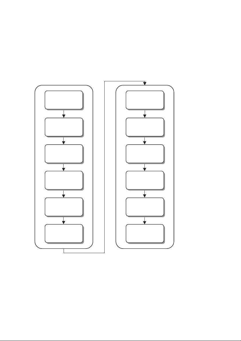
Access Control Workflow
The following workflow illustrates the recommended method for
working with the Access Control module:
Plan and Prepare the
Plan and Prepare the
Access Control Da ta
Access Control Da ta
(Chapter 3)
(Chapter 3)
Create a
Create a
Doors Table
Doors Table
Create a
Create a
Readers Table
Readers Table
Create a Time
Create a Time
Windows Table
Windows Table
Create a Weekly
Create a Weekly
Programs Table
Programs Table
Create an Access
Create an Access
Groups Table
Groups Table
Program the Access
Program the Access
Control Module
Control Module
(Chapter 4)
(Chapter 4)
Access the Access
Access the Access
Control Menu
Control Menu
Configure Door
Configure Door
and Reader
and Reader
Sett ings
Sett ings
Configure Time
Configure Time
S che dules
S che dules
Configure
Configure
Access Groups
Access Groups
Add Users to
Add Users to
the System
the System
Create a User
Create a User
Settings Table
Settings Table
Configure User
Configure User
Settings
Settings
10 Access Control User's Manual
Page 11

Chapter 2: Using the Access Control
Module
Entering/Exiting Doors
To enter/exit the system:
Arming/Disarming the System
The Access Control module can be used to allow
entering/exiting doors and for arming/disarming the security
system.
Doors that are defined to operate in automatic mode can be
entered/exited by all users with access cards or access codes.
The access card or code must:
x Used only during its assigned time windows.
x Used only with its assigned doors.
In addition, doors can be programmed to have a fixed status
(Always Open or Always Closed) or can be programmed to
open when a motion detector detects movement. In this case,
users can enter/exit normally without using their access card or
code.
¾
x Present your card or code to the reader, using the required
method (depending on the reader type). The system verifies
the card or code (indicated by a confirmation LED and
beep) and opens the door.
NOTES:
If a wrong code or an unknown card is entered five times, a false code
announcement is sent to the monitoring station.
Users with Entrance Only cards cannot enter a door if all the door
partitions are armed (refer to Adding Enter/Exit Users, page 29).
The system can be armed/disarmed only by users who have
been assigned with arm/disarm rights. To arm/disarm the system,
the following criteria must be met:
Access Control User's Manual 11
Page 12

x The reader must be authorized for the arming/disarming
Arming the System
To arm the system:
Disarming the System
operations.
x The access card/code must be programmed as an
Arm/Disarm user.
x The access card/code must be used only during its assigned
time windows.
x The access card/code must be used only with its assigned
doors.
x The access card/code must be assigned to the partitions that
are assigned to the door and to the user partition definitions
in the security panel.
NOTES:
Users can perform regular arming or instant arming, depending on the arm code. Ask
your Installer for the appropriate code. The system will arm only the partitions that are
common to the door, user security, and the arm user definitions.
Arming the system can be performed only from readers that
have a keypad and have been authorized for the arming
operation.
¾
x If the reader is defined as a Keypad Only type, enter your
arm code followed by your PIN code:
ARM CODE + [#] + PIN CODE + [#]
-OR-
x If the reader is defined as a Keypad + Card type (for higher
security), enter your arm code using the keypad, pass your
access card in the reader, and then enter your PIN code
using the keypad:
ARM CODE + [#] + PASS CARD + PIN CODE + [#]
IMPORTANT:
If you do not succeed in arming the system, refer to the checklist in
Appendix A, Why Your System Does Not Arm, page 37.
Disarming the system can be performed from any type of reader
that has been authorized for the disarming operation.
12 Access Control User's Manual
Page 13

¾
To disarm the system:
Duress Disarming
To perform duress disarming:
x If the reader is defined as a Keypad Only or Card Only or
Keypad/Card type, enter your PIN code using the keypad
OR pass your access card in the reader, as required:
PIN CODE + [#] or PASS CARD
-OR-
x If the reader is defined as a Keypad + Card type, pass your
access card in the reader AND then enter your PIN code
using the keypad:
PASS CARD + PIN CODE + [#]
You can also use the Access Control readers (Keypad Only,
Keypad/Card, and Keypad + Card types) for duress disarming.
This type o f disarmin g sends a quiet alarm to the monitoring
station while you disarm the system under coerciveness.
The duress code is automatically the number following the user's
PIN code (for example: PIN code = 1234; duress code = 1235).
Refer to the ProSYS User's Manual for additional details.
¾
x If the reader is defined as a Keypad Only or a Keypad/Card
type, enter the next sequential number after your PIN code:
[PIN CODE + 1] + [#]
-OR-
x If the reader is defined as a Keypad + Card type, pass your
access card in the reader and then enter the next sequential
number after your PIN code:
PASS CARD + [PIN CODE + 1] + [#]
Access Control User's Manual 13
Page 14

Chapter 3: Planning and Preparing the
Access Control Data
To plan and prepare the Access Control data:
Before programming the Access Control module, you must plan
how you want the system to function, such as which hours entry
will be permitted through the main entrance, who should have
access to specific areas of the premises, and so on. As part of
the planning, it is recommended to prepare the data that will be
used during programming in tables, as described in this section.
¾
1) Create a table that includes the following door data for each
door: number, name, location, mode, and partition. The
table should be based on information from your Installer.
(Refer to the table provided in Table 1: Doors, page 38.)
2) Create a table that includes the following reader data for
each reader: number, associated door, name, type, and
arm/disarm capabilities. The table should be based on
information from your Installer. (Refer to the table provided in
Table 2: Readers, page 39.)
3) Create two time schedule tables, as described below.
The purpose of creating time schedules is to give different
users access to doors at different hours. This consists of
identifying the different types of working hours or other time
divisions in the premises and then deciding what time
schedule will be used.
NOTE:
When you program the time schedules, you must program the time
windows first, and then you can program the weekly programs for each
access group.
Create a table that includes the following time window
data: number, program name, and one or two start and
stop times, as required. (Refer to the table provided in
Table 3: Time Windows, page 40.)
14 Access Control User's Manual
Page 15

Create a table that includes the following weekly
program data: number, program name, and assigned
Time Window numbers for each day of the week and for
a holiday. (Refer to the table provided in Table 4: Weekly
Programs, page 41.)
4) Create a table that includes the following access group data
for each group: number, name, allowed doors, and assigned
weekly program. The purpose of creating access groups is to
identify the different departments or sections in the company
and decide which group can enter which department at
what time. (Refer to the table provided in Table 5: Access
Groups,
page 42.)
5) Create a table that includes the following user data for each
user: number, name, access card code number, PIN code,
and assigned access group. This table enables you to easily
keep track of your user information. (Refer to the table
provided in Table 6: User Settings, page 43.)
Access Control User's Manual 15
Page 16

Chapter 4: Programming the Access
Control Module
66
66
66
66
66
66
66
This chapter provides detailed instructions for programming the
functions of the Access Control module, as well as describes the
related quick key combinations.
NOTE:
The programming instructions described in this chapter are based on the same
concepts as those described in the ProSYS User's Manual.
This chapter includes the following sections:
88
CODECODE
88
CODECODE
##
Accessing the Access Control Menu, page 17
## 11
Configuring Door and Reader Settings, page
17
88
CODECODE
88
CODECODE
88
CODECODE
88
CODECODE
88
CODECODE
## 22
Configuring Time Schedules, page 20
## 33
Configuring Access Groups, page 24
## 44
Adding Users to the System, page 25
## 55
Configuring User Settings, page 33
## 66
Opening Doors, page 36
Some of the Access Control programming options have been
pre-programmed by the Installer (refer to the ProSYS Installation
and Programming Manual). In addition, a detailed description of
how to use the keypad is provided in the ProSYS User's Manual.
IMPORTANT:
Ensure that your security system is disarmed before you program any of the
Access Control functions and also that all the Access Control modules are
connected to the Main Panel.
16 Access Control User's Manual
Page 17

Accessing the Access Control Menu
66
88
To access the Access CControl menu:
Configuring Door and Reader Settings
66
Defining the Door Mode
66
CODECODE
All functions in this manual are performed from the Access
Control menu.
¾
1) From the initial keypad display, enter the [] User Functions
mode and select [8] Access Control.
The following option is displayed:
INSERT CODE:
_ _ _ _
2) Enter the current Master Code or the Manager Code and
press
The first option of the Access Control menu is displayed, as
shown in the next section. You can now program the
required Access Control options, as described in the
subsequent sections of this manual.
.
##
88
CODECODE
Configuring the Access Control settings consists of defining the
door mode for each door and the reader type for each reader
in the system, as described in the following sections:
x Defining the Door Mode, below
x Defining the Reader Type, page 19
The door mode option enables you to determine the status of
the electric strike on each door. For example, during a weekend
period, you may want a specific door to be closed at all times to
prevent people from entering the premises.
When performing this procedure, use the data that you
prepared in Table 1: Doors, page 38.
Access Control User's Manual 17
## 11
88
CODECODE
## 11 11
Page 18

¾
To define the door mode:
1)
ACCESS CONTROL:
ACCESS CONTROL:
1) SETTINGS
1) SETTINGS
2)
3)
SETTINGS:
SETTINGS:
1) DOOR MODE
1) DOOR MODE
SELECT A DOOR:
SELECT A DOOR:
01) DOOR 01
01) DOOR 01
From the Access Control menu, select
[1] Settings.
Select [1] Door Mode.
Select the appropriate door number
and then press
. The first door
mode option is displayed.
4)
DOOR MODE:
1) AUTOMATIC
Define the door mode (status of the
door electric strike) by selecting the
appropriate option number:
[1] Automatic: Sets the door relay to automatic mode.
This enables access to any user with access rights when
introducing a card or code to the reader.
NOTE:
This is the default door mode, which is generally used for everyday purposes.
[2] Always Open: Sets the door relay to always open
mode. This option keeps the door open at all times and is
used when you want to keep the door open but do not
want an alarm to occur, for example, when
merchandise is being delivered.
[3] Always Closed: Sets the door relay to always closed
mode. This option keeps the door closed at all times and
is used to prevent people from using the door, for
example, during a weekend period.
18 Access Control User's Manual
Page 19

Defining the Reader Type
66
To define the reader type:
88
CODECODE
## 11 22
The reader type option enables you to define the access type
and level of security for each reader. This consists of defining
which type of reader is installed on each door and defining
whether or not the system can be armed and/or disarmed from
the reader. For example, you may have two readers at the
entrance of your premises, but you only want the system to be
armed from the inside reader and disarmed from the outside
reader.
NOTES:
The reader type depends on the installed reader.
The system enables you to have different reader technologies throughout your
premises, but each Access Control module can support only one technology.
When performing this procedure, use the data that you
prepared in Table 2: Readers, page 39.
¾
1)
ACCESS CONTROL:
ACCESS CONTROL:
1) SETTINGS
1) SETTINGS
2)
3)
4)
SETTINGS:
SETTINGS:
1) DOOR MODE
1) DOOR MODE
SELECT A READER:
SELECT A READER:
01) READER 01
01) READER 01
READER TYPE
READER TYPE
1) CARD ONLY
1) CARD ONLY
From the Access Control menu,
select
[1] Settings.
Select [2] Reader Type.
Select the appropriate reader
number and then press
.
Define the reader type (depending
on the installed reader type) by
selecting the appropriate option:
[1] Card Only: Enables door access by using an
access card in the reader. After selecting this option,
select [Y] Yes or
[N] No to define the disarm rights. (This option only
allows users to disarm the system.)
Access Control User's Manual 19
Page 20

[2] Keypad Only: Enables door access by entering a
Configuring Time Schedules
66
Defining Time Windows
66
code using the installed keypad. After selecting this
option, select [Y] Yes or [N] No to define the arm rights
and then, at the next option, select [Y] Yes or [N] No to
define the disarm rights.
[3] Keypad + Card: Enables door access by using an
access card in the reader in addition to entering a
code using the installed keypad. After selecting this
option, select [Y] Yes or [N] No to define the arm rights
and then, at the next option, select [Y] Yes or [N] No to
define the disarm rights. (This option is used for higher
security.)
[4] Keypad/Card: Enables door access either using an
access card in the reader or by entering a code using
the installed keypad. After selecting this option, select
[Y] Yes or [N] No to defin e the disarm rights. (This
option only allows users to disarm the system.)
You can configure the time schedules by
which users can access the system. This
1
1
Define Time
Define Time
Windows
Windows
88
CODECODE
## 22
consists of first defining daily time windows, as
described below, and then defining the
2
2
Define Weekly
Define Weekly
Programs
Programs
weekly programs that are based on the
required schedules of the users, as described
on page 22.
NOTE:
The time windows in the weekly programs that are defined for holidays will work
during the holiday dates that are defined in Quick Keys [6][6][2] in the ProSYS
User's Manual.
88
CODECODE
## 22 11
The time window option enables you to create daily time
windows that determine when users can access the system. You
can define up to 25 time windows, which consists of assigning a
logical name and two time intervals to each time window. You
must define time windows for each group of users, as you will use
20 Access Control User's Manual
Page 21

these time windows to later build the weekly programs for each
Time
Window
Program Name Start
Time 1
Stop
Time 1
Start
Time 2
Stop
Time 2
To define a time window:
group.
The following example shows different time windows defined to
allow access to different groups only during certain time periods:
1 Markt Personnel 08:00 12:00 12:30 19:00
2 Cleaning Day 08:00 12:00 12:30 16:00
3 Cleaning Night 15:00 19:00 19:30 23:00
4 Half Day Work 08:00 14:00 14:00 14:00
NOTE:
The time intervals that you define for the time windows must be in ascending
order. For example, the system will not enable you to enter the start time 17:00
before the end time 08:00 for a specific time window.
When performing this procedure, use the data that you
prepared in Table 3: Time Windows, page 40.
¾
1)
ACCESS CONTROL:
ACCESS CONTROL:
1) SETTINGS
1) SETTINGS
2)
TIME SCHEDULE:
TIME SCHEDULE:
1) TIME WINDOW
1) TIME WINDOW
3)
SELECT PROGRAM:
SELECT PROGRAM:
01) T. WINDOW 01
01) T. WINDOW 01
From the Access Control menu,
select [2] Time Schedule.
Select [1] Time Window.
Enter a program number (1-25) and
press
.
4)
TIME WINDOW 01
TIME WINDOW 01
START1 00:00
START1 00:00
Enter the s tart time of the first tim e
interval in HH:MM format and press
.
5)
TIME WINDOW 01
TIME WINDOW 01
STOP1 00:00
STOP1 00:00
Enter the stop time of the first time
interval in HH:MM format and press
.
6)
TIME WINDOW 01
TIME WINDOW 01
START2 00:00
START2 00:00
Enter the start time of the second
time interval in HH:MM format and
press
.
Access Control User's Manual 21
Page 22

7)
Defining Weekly Programs
66
ID Name Mon Tue Wed Thu Fri Sat Sun Hol
TIME WINDOW 01
TIME WINDOW 01
STOP2 00:00
STOP2 00:00
Enter the stop time of the second
time interval and press
.
8)
T. WINDOW LABELT. WINDOW LABEL
9)
TIME WINDOW 01
TIME WINDOW 01
IS DEFINED
IS DEFINED
Enter a logical name for the time
window and press
.
This message indicates that the time
window has been defined
successfully.
88
CODECODE
## 22 22
The weekly program option enables you to define weekly
programs for each group of users. Each weekly program is
comprised of seven separate time windows and one holiday
time window that you select, which then determine the days and
time intervals during which each group has access to the system.
The time window that you select for the holiday time window
determines how the permissions for the assigned access group
will act once the system goes into holiday mode.
NOTES:
Before defining weekly programs, you must first define the time windows, as
described in the previous section.
Weekly programs are required when you define access groups, as described in
Configuring Access Groups, page 24.
You can define up to 25 weekly programs. For example, you can
create a weekly program named Markt Weekly that consists of
the Markt Personnel time window for Monday through Thursday;
the Half Day Work time window for Friday; and the Never time
window for weekends and holidays, as shown in the table below.
Markt
1
Weekly
Cleaning
2
Night
x Time Window 1: Markt Personnel
x Time Window 2: Half Day Work
x Time Window 00: Never
1 1 1 1 2 00 00 00
3 3 3 3 2 00 00 00
When performing this procedure, use the data that you
prepared in Table 4: Weekly Programs, page 41.
22 Access Control User's Manual
Page 23

¾
To define a weekly program:
1)
ACCESS CONTROL:
ACCESS CONTROL:
1) SETTINGS
1) SETTINGS
2)
TIME SCHEDULE:
TIME SCHEDULE:
1) TIME WINDOW
1) TIME WINDOW
3)
SELECT PROGRAM:
SELECT PROGRAM:
01) WEEKLY 01
01) WEEKLY 01
4)
5)
CHOOSE DAY
CHOOSE DAY
1) SUNDAY
1) SUNDAY
SET TIME WINDOW
SET TIME WINDOW
01) T. WINDOW 01
01) T. WINDOW 01
From the Access Control menu,
select
[2] Time Schedule.
Select [2] Weekly Prog.
Enter a weekly program number (1-
25) and press
.
Select [1] Sunday and press
Assign a time window for Sunday
by scrolling through the list of
defined daily time windows and
then pressing
at the
appropriate one.
NOTE:
In addition to the list of time windows that have been defined in the
system, the [99] Always (default) and [00] Never options are available.
6)
CHOOSE DAY
CHOOSE DAY
2) MONDAY
2) MONDAY
NOTE:
You can press [] at any time during the programming to exit the weekly
programming option and save the changes that were defined.
The option for the next day is
displayed automatically.
.
7) Repeat steps 4 to 6 for the other days of the week (as
well as for the [8] Holiday option), by selecting the
appropriate option number and then pressing Enter
after each one.
8)
ENTER PROG LABEL
ENTER PROG LABEL
WEEKLY 01
WEEKLY 01
Enter a logical name for the weekly
program, for example, Markt
Weekly
(up to 12 characters), and press
Enter.
9)
WEEKLY PROG 01
WEEKLY PROG 01
IS DEFINED
IS DEFINED
This message indicates that the
weekly program has been defined
successfully.
Access Control User's Manual 23
Page 24

Configuring Access Groups
66
To configure an access group:
W
W
88
CODECODE
## 33
After defining the door mode, reader type, and the time
schedules, you can configure access groups. Each access group
represents the doors that groups of users can access during
specific time periods.
You can configure up to 16 access groups in the system, which
consists of assigning a logical name to the access group and
then assigning up to 16 doors, each with its own weekly program,
to the access group. Afterwards, you will assign each individual
user to the appropriate access group, as described in Assigning
Users to Access Groups, page 34.
For example, you can configure an access group named Markt
Personnel that represents a group of users that have access to
doors 1, 7 and 8, according to the weekly program named Markt
Weekly that you defined earlier. Then you can configure another
access group named Cleaning Personnel that represents a
group of users that only has access to doors 7 and 8 and only
during the time periods defined in the weekly program named
Cleaning Night (i.e., Mon-Fri, 17:00 to 19:00).
NOTE:
Changes that you make to access group definitions directly affect the users
assigned to the groups.
When performing this procedure, use the data that you
prepared in Table 5: Access Groups, page 42.
¾
1)
ACCESS CONTROL:
ACCESS CONTROL:
1) SETTINGS
1) SETTINGS
2)
SELECT GROUP:
SELECT GROUP:
01) GROUP 01
01) GROUP 01
3)
4)
EEKLY PROGRAM:
EEKLY PROGRAM:
01) WEEKLY 1
01) WEEKLY 1
GROUP 1
GROUP 1
1) DOOR 01
1) DOOR 01
From the Access Control menu,
select
[3] Group Access.
Enter a group number (1-16).
Select a door number for the
selected group and press
Select a weekly program (1-25) for
the selected door and press
.
.
24 Access Control User's Manual
Page 25

NOTE:
Adding Users to the System
66
When a Code Entry Fails
In addition to the list of weekly programs that have been defined in the
system, the [99] Always (default) and [00] Never options are available.
5) Repeat steps 3 and 4 to define additional doors and
their associated weekly programs to the access
group, as required.
6)
ENTER GROUP NAME
After you have selected weekly
programs for the available doors, this
option is displayed. Enter a logical
name for the group and press
.
7)
ACCESS GROUP 01
ACCESS GROUP 01
IS DEFINED
IS DEFINED
This message indicates that the
access group has been defined
successfully.
88
CODECODE
## 44
The record users option enables you to add two types of users to
the system, as follows:
x Adding Arm/Disarm Users, page 26
x Adding Enter/Exit Users, page 29
NOTE:
This option is only enabled when the Access Control module is connected to the
security system.
When performing these procedures, use the data that you
prepared in Table 6: User Settings, page 43.
When adding both types of users to the system, if the user
number has already been used, a message is displayed,
providing you with the option to overwrite the user data. In
addition, if the card code has already been used in the system,
a message is displayed, indicating that the card code exists,
followed by three beeps.
Access Control User's Manual 25
Page 26

Adding Arm/Disarm Users
66
By Entering a Card Code
66
88
CODECODE
## 44 11
The record users option enables you to add up to the maximum
number of users that are currently defined in your security system
with arm/disarm access rights in the following ways:
x By Entering a Card Code, below
x By Passing a Card in a Reader, page 29
When adding arm/disarm users, you must also select any
partition which each user is allowed to arm/disarm. For example,
you can assign only partitions 1, 2, and 3 to allow the user
arm/disarm rights to the Marketing Department and the kitchen
facilities, but prevent arm/disarm rights to the other areas where
the management offices are located (thus creating a "walking
path").
NOTES:
Arm/disarm users can only arm the system from readers for which you
configured arm/disarm capabilities in the reader type definitions (refer to
Defining the Reader Type, page 19).
The system will arm only the partitions that are common to the door, user
security, and the arm user definitions.
88
CODECODE
## 44 11 11
You can add arm/disarm users to the system by manually
entering the 8-digit code on each user's access card using an
installed keypad. This, in effect, enables you to add users by
remote programming.
This option is recommended when using RISCO Group cards that
contain 8-digit numbers on the face of the cards. If you are using
cards other than RISCO Group cards or cards with less than 8
digits, it is recommend ed to add the users by passing the card s,
as described in By Passing a Card in a Reader, page 31.
26 Access Control User's Manual
Page 27

¾
To add an arm/disarm user by entering a card code:
By Passing a Card in a Reader
66
1)
ACCESS CONTROL:
ACCESS CONTROL:
1) SETTINGS
1) SETTINGS
2)
3)
4)
5)
6)
RECORD USERS
1) ARM CARDS
ARM CARDS 00-98
ARM CARDS 00-98
1) BY CARD CODE
1) BY CARD CODE
SELECT USER:
SELECT USER:
00 (00-98)
00 (00-98)
USER 00 12345678
USER 00 12345678
PAR: Y.......
PAR: Y.......
U:00 CARD CODE
U:00 CARD CODE
........
........
7)
U:00 INSERTION
CONFIRMED
From the Access Control menu,
select
[4] Record Users.
Select [1] Arm Cards.
Select [1] By Card Code.
Enter a user number between 00-98
and press
. The first available
user number is displayed as the
default.
Assign between 1 and 8 partitions to
the user by pressing [Y] Yes or [N] No,
as required, and then press
Enter the 8-digit card code of the
access card that you want to assign
to the user and press
.
This message indicates that the
arm/disarm user has been added to
the system successfully.
.
88
CODECODE
## 44 11 22
You can add arm/disarm users to the system by passing each
user's access card in a reader. This option is recommended when
you have access cards without numbers printed on them or
when the cards have less than eight digits printed on them.
Access Control User's Manual 27
Page 28

¾
To add an arm/disarm user by passing a card in a reader:
1)
ACCESS CONTROL:
ACCESS CONTROL:
1) SETTINGS
1) SETTINGS
2)
3)
4)
5)
6)
RECORD USERS
1) ARM CARDS
ARM CARDS 00-98
ARM CARDS 00-98
1) BY CARD CODE
1) BY CARD CODE
GET INSTALLATION
GET INSTALLATION
READER:
READER:
SELECT USER:
SELECT USER:
00 (00-98)
00 (00-98)
USER 00 12345678
USER 00 12345678
PAR: Y.......
PAR: Y.......
From the Access Control menu,
select
[4] Record Users.
Select [1] Arm Cards.
Select [2] Pass Card. The green
reader LED flashes for 12 seconds
while the reader waits for the card. If
you do not pass a card, the reader
emits an error beep.
Select the reader number that you
want to use to pass the card and
press
Enter.
Enter a user number between 00-98
and press
.
Assign between 1 and 8 partitions to
the selected user by pressing [Y] Yes
or
[N] No, as required, and press
.
7)
PASS THE CARD IN
THE DOOR READER
8)
U:00 INSERTION
CONFIRMED
Physically pass the card in the
installed reader and wait for the
confirmation beep.
This message indicates that the
arm/disarm user has been added to
the system successfully.
28 Access Control User's Manual
Page 29

Adding Enter/Exit Users
66
By Entering Card Codes for a Group
66
To enter card codes for a group of enter/exit users:
88
CODECODE
## 44 22
You can add up to 999 users that have only enter/exit access
rights to the system in the following ways:
x By Entering Card Codes for a Group, below
x By Entering Card Codes One-by-One, page 30
x By Passing a Card in a Reader, page 31
NOTE:
Enter/exit users can only open doors; not arm/disarm the system.
If you have different categories of users, it is recommended to
assign a different block of numbers to each access group. This
makes it easier to allocate each category to the required time
schedule. For example, you can assign user numbers 100-199 to
Access Group 1, 200-299 to Access Group 2, and so on.
88
CODECODE
You can add a group of enter/exit users by assigning a batch of
cards in ascending order. For example, you can add a group of
100 cards with sequential user numbers by only entering the first
card code, and the system enters the remaining information
automatically.
NOTE:
When entering card codes for a group, if the system detects a problem, the
process will stop automatically.
## 44 22 11 11
¾
1)
ACCESS CONTROL:
ACCESS CONTROL:
1) SETTINGS
1) SETTINGS
2)
3)
RECORD USERS
1) ARM CARDS
EN. CARDS 100-999
1) BY CARD CODE
From the Access Control menu,
select
[4] Record Users.
Select [2] Entrance Card.
Select [1] By Card Code.
Access Control User's Manual 29
Page 30

4)
By Entering Card Codes One by One
66
CODE ALLOCATION
1) BY GROUP
5)
FIRST USER NO.
FIRST USER NO.
100 100-999
100 100-999
Select [1] By Group.
Enter a user number between 100999 and press
. The first
available user number is displayed
as the default.
6)
NUMBER OF USERS
IN GROUP:001
7)
FIRST CARD CODE
FIRST CARD CODE
........
........
Enter the number of users that are in
the group that you want to add to
the system and press
.
Enter the 8-digit card code number
of
the access card that you want to
assign
to the first user in the group and
press
. The system automatically
assigns a sequential card code
number to each user in the group.
8)
GROUP INSERTION
CONFIRMED
This message indicates that the
group of enter/exit users has been
added to the system successfully.
88
CODECODE
You can add a group of enter/exit users one at a time, if
required. This option is used when assigning a batch of cards that
are not sequential or when assigning a batch of cards from a
remote keypad that is not located near a reader.
## 44 22 11 22
If the code on the access card is less than 8 digits, it is
recommended to swipe the card instead of entering zeros for
the remaining digits. Refer to By Passing a Card in a Reader,
page 31.
30 Access Control User's Manual
Page 31

¾
To enter card codes for a group of enter/exit users one by one:
By Passing a Card in a Reader
66
1)
ACCESS CONTROL:
ACCESS CONTROL:
1) SETTINGS
1) SETTINGS
2)
3)
4)
5)
6)
7)
RECORD USERS
1) ARM CARDS
EN. CARDS 100-999
1) BY CARD CODE
CODE ALLOCATION
1) BY GROUP
SELECT USER:
SELECT USER:
100 100-999
100 100-999
U:100 CARD CODE
U:100 CARD CODE
........
........
U: 100 INSERTION
CONFIRMED
From the Access Control menu,
select
[4] Record Users.
Select [2] Entrance Card.
Select [1] By Card Code.
Select [2] One by One.
Enter a user number between 100999 and press
. The first
available user number is displayed
as the default.
Enter the 8-digit card code of the
access card that you want to assign
to the first user and press
.
This message indicates that the first
enter/exit user has been added to
the system successfully, and then the
Select User option is redisplayed.
8) Repeat steps 5 to 7 to add the remain ing enter/exit
users in the group, as required.
88
CODECODE
## 44 22 22
You can add enter/exit users by passing each user's card in a
reader without returning to the keypad. This option is used in the
following circumstances:
x When you have access cards without numbers printed on
them.
x When the cards have less than eight digits printed on them.
x When you have a batch of cards without sequential
numbering.
Access Control User's Manual 31
Page 32

¾
To add an enter/exit user by passing a card in a reader:
1)
ACCESS CONTROL:
ACCESS CONTROL:
1) SETTINGS
1) SETTINGS
2)
3)
4)
RECORD USERS
1) ARM CARDS
EN. CARDS 100-999
1) BY CARD CODE
GET INSTALLATION
READER: 01
From the Access Control menu,
select
[4] Record Users.
Select [2] Entrance Card.
Select [2] Pass Card.
Enter the reader number that you
want
to use to pass the card and press
Enter.
5)
FIRST USER NO.
FIRST USER NO.
100 100-999
100 100-999
Enter a user number between 100999 and press
. The first
available user number is displayed
as the default.
6)
PASS THE CARD IN
THE DOOR READER
7)
U:100 INSERTION
CONFIRMED
NOTE:
If you are performing this procedure on a remote reader, you will not see
the message shown above.
Physically pass the card in the
installed reader and wait for the
confirmation beep.
This message indicates that the
enter/exit user has been added to
the system successfully.
8) Repeat step 6 to record additional cards, as required.
9) In order to stop the recording process, pass a card
that has already been introduced into the system.
32 Access Control User's Manual
Page 33

Configuring User Settings
66
Assigning PIN (Personal Identification Number) Codes
66
To assign a PIN code:
88
CODECODE
## 55
You can define settings for users of the system, including
assigning PIN (Personal Identification Number) codes, assigning
users to specific access groups, and deleting users, as described
in the following sections:
x Assigning PIN Codes, below
x Assigning Users to Access Groups, page 34
x Deleting Users, page 35
88
CODECODE
The PIN code option enables you to assign one PIN code to each
individual user, which is required if your system has readers with
keypads installed. The system automatically assigns a duress
code to each user's PIN code, which is one number after the
user's
PIN code (for example: PIN code = 1234; automatic duress
code = 1235). Therefore, you cannot assign sequential PIN codes
to users in the system. You must use every other number, for
example, 1234, 1236, 1238, and so on.
NOTES:
The PIN CODE must be defined after assigning a card to a user or else it will be
erased.
For users 00-98 it is recommended to use the same PIN code that was used in
your security system.
If you enter a sequential number by mistake, the following message is
displayed: PIN CODE FAILED
## 55 11
¾
1)
ACCESS CONTROL:
ACCESS CONTROL:
1) SETTINGS
1) SETTINGS
2)
USER SETTINGS
1) PIN CODE
From the Access Control menu,
select
[5] User Settings.
Select [1] PIN Code.
Access Control User's Manual 33
Page 34

3)
Assigning Users to Access Groups
66
To assign users to access groups:
4)
CHOOSE USER:
CHOOSE USER:
...
...
ENTER PIN CODE:
ENTER PIN CODE:
....
....
5)
PIN CODE
CONFIRMED
Enter the user's number and press
Enter.
Enter the user's PIN code and press
Enter.
This message indicates that the PIN
code has been assigned
successfully.
88
CODECODE
You can assign individual users or groups of users to the
appropriate access groups, which is performed by defining a
user range and then allocating the range to the access group.
Each user that you assign to a group will have access to the
system, depending on the parameters that you selected when
configuring the assigned access group (refer to Configuring
Access Groups, page 24).
NOTE:
Each user in the system can be assigned to only one access group.
¾
1)
ACCESS CONTROL:
ACCESS CONTROL:
1) SETTINGS
1) SETTINGS
2)
USER SETTINGS
1) PIN CODE
3)
ENTER USERS:
ENTER USERS:
FROM:... TO:...
FROM:... TO:...
From the Access Control menu,
select
[5] User Settings.
Select [2] Assign Group.
Enter the first and last user numbers
in the range of users that you want
to add to the access group and
press
Enter.
NOTE:
When entering a range of users, the number entered in the From field
must always be lower than or equal to the number entered in the To field.
## 55 22
4)
ASSIGN TO GROUP:
ASSIGN TO GROUP:
01) GROUP 01
01) GROUP 01
Enter a group number (01-16).
34 Access Control User's Manual
Page 35

5)
Deleting Users
66
To delete a user from the system:
GROUP ALLOCATION
CONFIRMED
The following message is displayed,
confirming that the group
assignment was successful.
88
CODECODE
## 55 33
The user delete option enables you to remove individual users or
groups of users from the system. This can be required, for
example, when a user's card has been stolen or when a specific
user no longer works at your premises and therefore no longer
requires access.
¾
1)
ACCESS CONTROL:
ACCESS CONTROL:
1) SETTINGS
1) SETTINGS
2)
USER SETTINGS
1) PIN CODE
3)
ENTER USERS:
ENTER USERS:
FROM:... TO:...
FROM:... TO:...
NOTE:
When entering a range of users, the number entered in the From field
must always be lower than or equal to the number entered in the To field.
4)
***DELETE***
***DELETE***
ARE YOU SURE? N
ARE YOU SURE? N
From the Access Control menu,
select
[5] User Settings.
Select [3] Delete Users.
Enter the first and last user numbers
in the range of users that you want
to delete and press
.
Select [Y] Yes or [N] No in the
confirmation message, as required,
and press
.
5)
USER DELETED
This message indicates that the user
has been deleted successfully.
Access Control User's Manual 35
Page 36

Opening Doors
66
To open a door:
88
CODECODE
## 66
You can use the security system to remotely open any door from
any keypad that has previously been defined in the system.
NOTE:
Only authority levels of the Grand Master or the Manager can perform this
procedure.
¾
1)
ACCESS CONTROL:
ACCESS CONTROL:
1) SETTINGS
1) SETTINGS
2)
SELECT A DOOR:
01) DOOR 01
3)
DOOR 01 IS
OPENED
From the Access Control menu,
select
select [6] Open Door.
Select the appropriate door number
and then press
.
The selected door is opened and this
confirmation message is displayed.
36 Access Control User's Manual
Page 37

Appendix A: Why Your System Does Not
Arm
If you do not succeed in arming the system, check that all the
following criteria are met:
The partitions you want to arm are in Ready mode.
REMEMBER:
Only the common partitions of the access user, the door partition
definitions, and the security user partition definitions will be armed.
The user is defined as an Arm/Disarm user.
The user is defined to the correct access group.
REMEMBER:
In order to define an access group, you must first define a weekly program
and assign it to a door.
The use of the card/code is in the authorized access time
window.
The correct arm code has been entered. (Ask your Installer
for the default code, if required.)
The correct PIN code has been entered.
The reader is authorized for the arming operation.
Access Control User's Manual 37
Page 38

Appendix B: Planning and Preparation
Tables
Table 1: Doors
Door
No.
Name
Door
Location
Door
Mode
Door
Partition
1
2
3
4
5
6
7
8
9
10
11
12
13
14
15
16
Door Modes: Automatic, Always Open, and Always Closed
38 Access Control User's Manual
Page 39

Table 2: Readers
Reader No.
Belongs to
Door
Reader
Name
Reader
Type
Arm Y/N Disarm Y/N
1
2
3
4
5
6
7
8
9
10
11
12
13
14
15
16
Reader Type: [1] Card Only; [2] Keypad Only; [3] Card + Keypad;
[4] Card/Keypad
Access Control User's Manual 39
Page 40

Table 3: Time Windows
No. Program Name
Start
Time 1
HH:MM
Stop
Time 1
HH:MM
Start
Time 2
HH:MM
Stop
Time 2
HH:MM
OTE:
he time intervals that you define for the time windows must be in ascending order.
or example, the system will not enable you to enter the start time 17:00 before the
nd time 08:00 for a specific time window.
40 Access Control User's Manual
Page 41

Table 4: Weekly Programs
Hol
Sat
Fri
Thu
Wed
Tues
Mon
Time Window Allocation
Sun
Program Name
Access Control User's Manual 41
Page 42

Table 5: Access Groups
No. Group Name Access Doors Weekly Program
1 Marketing
NOTE:
The table above shows an example of how you can set up the information for each
access group with up to 16 access doors. Duplicate this table, as required, for the
additional access groups in your system.
42 Access Control User's Manual
Page 43

Table 6: User Settings
User
No.
User Name
Card
Code #
PIN # Access Group
Access Control User's Manual 43
Page 44

Notes
44 Access Control User's Manual
Page 45

Notes
Access Control User's Manual 45
Page 46

46 Access Control User's Manual
Page 47

RISCO Group Limited Warranty
RISCO Group and its subsidiaries and affiliates ("Seller") warrants its products
to be free from defects in materials and workmanship under normal use for
24 months from the date of production. Because Seller does not install or
connect the product and because the product may be used in conjunction
with products not manufactured by the Seller, Seller can no t guarantee the
performance of the security system which uses this product. Sellers obligation
and liability under this warranty is expressly limited to repairing and
replacing, at Sellers option, within a reasonable time after the date of
delivery, any product not meeting the specifications. Seller makes no other
warranty, expressed or implied, and makes no warranty of merchantability
or of fitness for any particular purpose.
In no case shall seller be liable for any consequential or incidental damages
for breach of this or any other warranty, expressed or implied, or upon any
other basis of liability whatsoever.
Sellers obligation under this warranty shall not include any transportati on
charges or costs of installation or any liability for direct, indirect, or
consequential damages or delay.
Seller does not represent that its product may not be compromised or
circumvented; that the product will prevent any persona; injury or property
loss by burglary, robbery, fire or otherwise; or that the product will in all cases
provide adequate warning or protection. Buyer understands that a properly
installed and maintained alarm may only reduce the risk of burglary, robbery
or fire without warning, but is not insurance or a guaranty that such will not
occur or that there will be no personal injury or property loss as a result.
Consequently seller shall have no liability for any personal injury, property
damage or loss based on a claim that the product fails to give warning.
However, if seller is held liable, whether directly or indirectly, for any loss or
damage arising from under this limited warranty or otherwise, regardless of
cause or origin, sellers maximum liability shall not exce ed the purchase price
of the product, which shall be complete and exclusive remedy against
seller.
No employee or representative of Seller is authorized to change this
warranty in any way or grant any other warranty.
WARNING: This product should be tested at least once a week.
Access Control User's Manual 47
Page 48

Contacting RISCO Group
RISCO Group is committed to customer service and product
support. You can contact us through our website
(www.riscogroup.com) or at the following telephone and fax
numbers:
United Kingdom
USA
Tel: +44-161-655-5500
technical@riscogroup.co.uk
Italy
Tel: +39-02-66590054
support@riscogroup.it
Spain
Tel: +34-91-490-2133
support-es@riscogroup.com
France
Tel: +33-164-73-28-50
support-fr@riscogroup.com
Belgium
Tel: +32-2522-7622
support-be@riscogroup.com
All rights reserved.
Tel: +305-592-3820
support@riscogroupusa.com
Brazil
Tel: +55-11-3661-8767
support-br@riscogroup.com
China
Tel: +86-21-52-39-0066
support-cn@riscogroup.com
Poland
Tel: +48-22-500-28-40
support-pl@riscogroup.com
Israel
Tel: +972-3-963-7777
support@riscogroup.com
No part of this document may be reproduced in any form
without prior written permission from the publisher.
© RISCO Group 07/08 5IN128EACUM B
48 Access Control User's Manual
 Loading...