


QT454-403-5
Q-See QT454-403-5, QT426-818-5, QT454, QT474, QT446 User Manual
...
1
User Manual
QT4 Series
H.264 NETWORK DVR
MODEL QT454
QT474
QT428
QT426
QT446
QT4332
2 3
© 2010, 2011 Q-See. Reproduction in whole or in part without written permission is
prohibited. All rights reserved. This manual and software and hardware described herein, in
whole or in part, may not be reproduced, translated, or reduced to any machine-readable
form without prior written approval.
Trademarks: All brand names and products are trademarks or registered trademarks of their
respective owners.
Q-See is a registered trademark of DPS, Inc.
Disclaimer: The information in this document is subject to change without notice. The
manufacturer makes no representations or warranties, either express or implied, of any kind
with respect to completeness of its contents.
Manufacturer shall not be liable for any damages whatsoever from misuse of this product.
Thank You for Choosing a Q-See Product!
All of our products are backed by a conditional service warranty covering all hardware for 12
months from the date of purchase. Additionally, our products also come with a free exchange
policy that covers all manufacturing defects for one month from the date of purchase.
Permanent upgrading service is provided for the software and is available at www.Q-See.com.
Be certain to make the most of your warranty by completing the registration form online. In
addition to warranty and technical support benefits, you’ll receive notifications of product
updates along with free downloadable firmware updates for your DVR. Register today at
www.Q-See.com!
Please see the back of this manual for exclusions.
This manual is written for the QT4 family of DVRs. Not all features and capabilities are shared
across all models so you may see features described which are not applicable or available on
your machine. In addition you may see screen images that do not exactly match those on your
display.
This manual was accurate at the time it was completed. However, because of our ongoing
effort to constantly improve our products, additional features and functions may have
been added since that time and on-screen displays may change. We encourage you to
visit our website at www.Q-see.com to check for the latest firmware updates and product
announcements.
Throughout the manual we have highlighted warnings and other important information that will
assist you in operating your new system in a safe and trouble-free manner. Please take the
time to read and follow all instructions and pay attention to alerts as shown below:
About this Manual
NOTE! Text in blue boxes with the Information icon offer additional guidance
and explanations about how to make the most out of your system.
IMPORTANT! Red boxes with this icon indicate warnings. To prevent
possible injury or damage to the product, read all warnings before use.
Rev. 2.6 8/19/2011

4 5
1. INTRODUCTION 7
For Your Safety 7
Features 8
2. CONNECTIONS AND CONTROLS 10
Models
QT454 10
QT474 12
QT426 14
QT428 16
QT446 18
QT4332 20
2.2 Mouse 22
2.3 Remote Control 23
3. BASIC FUNCTIONS 24
3.1 Power On/Off 24
Power On 24
Power Off 24
3.2 The Control Bar 25
3.3 Live Viewing And Recording 26
Switching Video Output 26
Live Viewing 26
3.4 Live Playback 27
4. MAIN MENU SETUP 28
4.1 Basic Configuration 28
Login 28
Main Menu 29
Setup 29
4.2 Live Configuration 31
4.3 Record Configuration 33
4.4 Schedule Configuration 35
4.5 Alarm Configuration 36
Sensor 36
Motion 37
Video Loss 38
Other Alarm 38
Alarm Out 39
4.6 Network Configuration 40
4.7 User Management 44
4.8 Pan-Tilt-Zoom (PTZ) Configuration 45
4.9 Advanced 48
Time Search 49
Event Search 50
File Management 50
Image 51
5. BACKUP 52
6. DVR MANAGEMENT 53
6.1 INFORMATION 53
Event Information 54
Log Information 54
Network Information 54
Online User Information 55
6.2 Manual Alarm 55
6.3 Disk Management 55
6.4 Upgrade 56
6.5 Logoff 56
6.6 Shut Down 56
7. HARD DISK DRIVE 57
7.1 Installation/Removal 57
7.2 Calculating the Recording Capacity of a Hard Disk Drive 59
APPENDIX 60
Troubleshooting 60
Specifications 63
Q-SEE PRODUCT WARRANTY 65
Questions or Comments? Contact Us 66
TABLE OF CONTENTS

6 7
FOR YOUR SAFETY
To prevent damage to your Q-See product or injury to yourself or to others, read and
understand the following safety precautions in their entirety before installing or using this
equipment. Keep these safety instructions where all those who use the product will read them.
nCheck the unit and any accessories included in the package immediately after opening. If
items are missing or damaged, repackage and return to the point of purchase.
n
Use the proper power source. Only use the power adapter supplied with your system. Do
not use this product with a power source that applies more than the specified voltage (100240V AC).
nNever insert anything metallic into the DVR. Inserting anything into the DVR or its case can
be a source of dangerous electric shock.
nDo not operate in dusty areas. Avoid placing the DVR in places that are dusty.
nDo not expose this product to rain or use near water. If this product accidentally gets wet,
unplug it and contact an authorized dealer immediately.
nKeep product surfaces clean and dry. To clean the outside case of the DVR, gently wipe
using a lightly dampened cloth (only use water, do not use solvents).
nDo not operate this DVR without the cover securely in place. Do not attempt to do any
repairs to the DVR yourself. If there are unusual sounds or smells coming from the DVR,
unplug it immediately and contact Q-See technical support. Under no circumstances
should the cover be removed while the device is connected to a power source. You should
only remove the cover to install/replace the hard disk drive (See Chapter 7) or replace the
standard 3v lithium cell battery on the motherboard. These are the only user serviceable
parts. You may need to replace the battery if the internal clock resets itself after a power
outage
nHandle the DVR carefully. If you accidentally drop your DVR on any hard surface, it may
cause a malfunction. If the DVR doesn’t work properly due to physical damage, contact an
authorized dealer for repair or exchange.
nMake sure there is proper air circulation around the unit. This DVR system uses a hard drive
for video storage which generates heat during operation. Do not block air holes located on
the bottom, top, sides and back of the DVR as they are designed to keep the system cool
while running. Install or place this product in an area where there is ample air circulation.
nProvide proper ventilation. This DVR has a built-in fan that properly ventilates the system.
Do not cover or impede this fan.
INTRODUCTION
CHAPTER 1
WARNING! ELECTRIC SHOCK RISK!

8 9
FEATURES
This DVR uses high-performance video processing chips and an embedded Linux operating
system for quality image recording and ease of use. It utilizes numerous advanced
technologies including the industry-standard H.264 codec to deliver high-quality, smooth
videos and dual stream capability for remote viewing. A SATA hard-drive interface offers
upgradability and VGA output allows users to connect to any standard TV or monitor for
viewing.
Local control of the system utilizes a mouse and graphical user interface (GUI) as well as a
remote control. Users can also remotely monitor and control their system using a web browser
or select mobile device.
This DVR uses cutting-edge technology without compromising stability and reliability making it
ideal for home use as well as in warehouse, factory, retail and other similar environments.
COMPRESSION FORMAT
Standard H.264 compression with low bit rate and high image quality
LIVE SURVEILLANCE
Supports HD VGA output
Supports channel security by hiding live display
Displays the local record state and basic information
Supports full control with USB mouse
Supports digital zoom on live and playback view
RECORDING MEDIA
Supports SATA hard disk drives up to 2TB each for longer recording times.
BACKUP
Supports backing up to USB 2.0 devices
Some models support eSATA external hard drives
Supports saving recorded files with AVI format to a remote computer through
internet
RECORDING & PLAYBACK
Record modes: Manual, Schedule, Motion detection and Sensor alarm recording
Supports recycle after HDD is full
Resolution, frame rate and picture quality are adjustable
128MB for every video file packaging
Up to 16 audio channels available depending on model
Two record search modes: time search and event search
Supports multi-screen simultanious playback
Supports deleting and locking the recorded files one by one
Supports remote playback in Network Client through LAN or internet
Supports recording in CIF and D1 resolutions.
ALARM
1-4 channel alarm output and up to 16-channel (depending on model ) alarm input
available
Supports scheduling for motion detection and sensor alarm
Supports pre-recording and post recording
Supports linked channels recording once motion or alarm is triggered on
designated channel
Supports linked PTZ preset, auto cruise and track of the corresponding channel
PTZ CONTROL
Supports multiple PTZ protocols (PelcoP, PelcoD, LILIN, MINKING, NEON, STAR,
VIDO, DSCP, VISCA, and RANGE)
Supports 128 PTZ presets and 8 auto cruise tracks
Supports remote PTZ control through internet
SECURITY
Customize user rights: log search, system setup, two way audio, file management,
disk management, remote login, live view, manual record, playback, PTZ control
and remote live view
Supports 1 administrator and 15 users.
Supports event log recording and checking, events unlimited
NETWORK
Supports TCP/IP, DHCP, PPPoE, DDNS protocols
Supports IE browser to do remote viewing
Supports a maximum of 10 user connections simultaneously
Supports dual stream. Network stream is adjustable independently to fit the
network bandwidth and environment.
Supports picture snap and color adjustment in remote live view
Supports remote time and event search, and channel playback with picture snap
Supports remote PTZ control with preset and auto cruise
Supports remote full menu setup, changing all the DVR parameters remotely
Supports mobile surveillance by smart phones, Win Mobile Pro, Symbian, and
iPhones, iPads, Android, and Blackberry on 3G networks
Supports CMS to manage multiple devices on the internet
Administrator can limit user access to specific cameras
Administrator can disconnect online users
NOTE! Depending on your point of purchase, your DVR will have the hard
disk drive already installed. If your drive was packaged separately or if you
wish to upgrade to up to a 2TB drive, please see Chapter 7 at the back of
this manual which covers installing the drive.
10 11
CONNECTIONS AND CONTROLS
CHAPTER 2
1
10 11
3 52 4 2 6 8 97
1 3 4 5 6 7 8 9 10 112
12 13
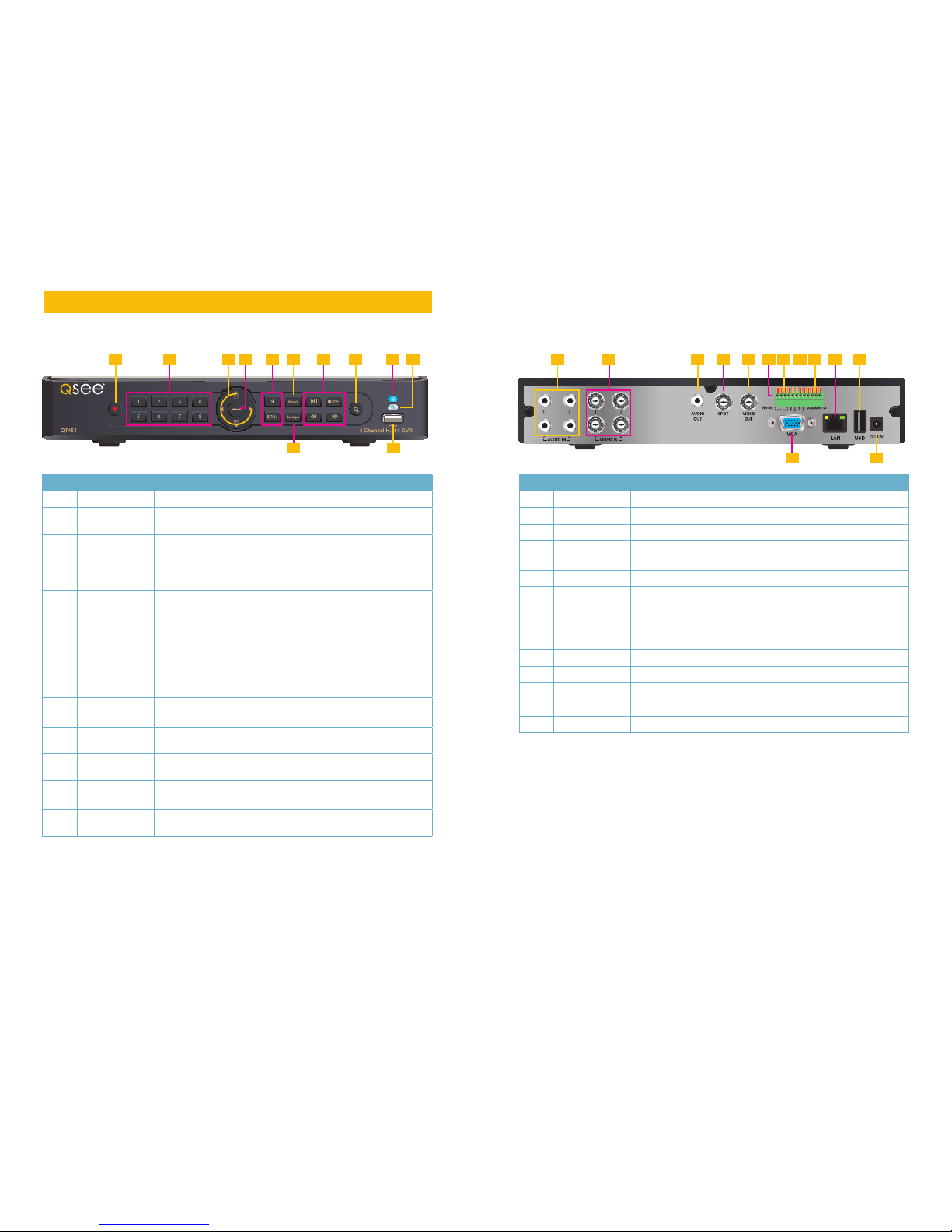
ITEM NAME FUNCTION
1 POWER Power On/Off
2
NUMBER
BUTTONS
Select individual channels and enter data where required
3 DIRECTION Navigates through selections in menus
Selects viewing mode - Full Screen or 4-Channel Multi-Screen
View
4 ENTER Confirm Selection
5 MENU Opens the Main Menu
Increases the value in Setup mode
6
PLAYBACK
CONTROLS
In addition to normal DVR playback and record operation, the
following have additional functions:
RECORD Controls Focus in PTZ mode
REVERSE Controls Speed in PTZ mode
STOP/ESC Exits current interface or status
Also switches video output mode.
7 SEARCH/
ZOOM
Enter Search mode
Controls Zoom function in PTZ mode
8
INDICATOR
LIGHT
Shows power status of the DVR
9
INFRARED
WINDOW
Receives signals from the remote control
10 BACKUP Enter Backup mode
Decreases the value in Setup mode
11
USB PORT Used for external USB backup devices. The mouse will not
function in this port.
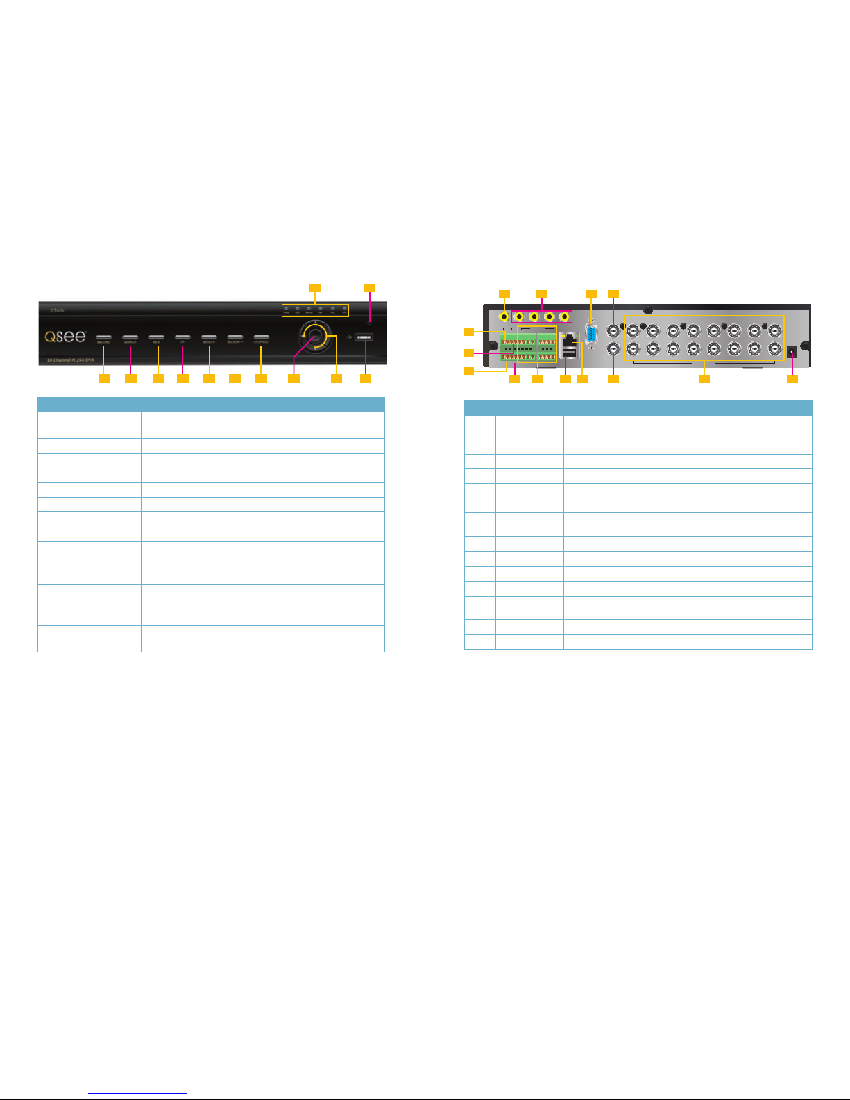
ITEM NAME FUNCTION
1
AUDIO IN 4 Channels of audio input
2 VIDEO IN Video input from up to 4 cameras
3
AUDIO OUT Audio output for amplified speaker
4
SPOT OUT Connect to another monitor as an auxiliary output channel. This
monitor will only display video and will have no menu access.
5
VIDEO OUT BNC connector for TV or monitor
6 PTZ Connections for Pan-Tilt-Zoom speed dome cameras. Y = “+” Z
= “-”
7 K/B Connector for a PTZ keyboard
8
ALARM OUT 1 Channel relay output for external alarms
9
ALARM IN 4 Channel input for exter nal sensors and alarms
10 LAN Network (ethernet) port
11
USB PORT For the USB mouse
12
VGA PORT VGA output for 19” or larger monitor
13
DC IN Power input for 12V DC power supply
FRONT PANEL
QT454
REAR PANEL
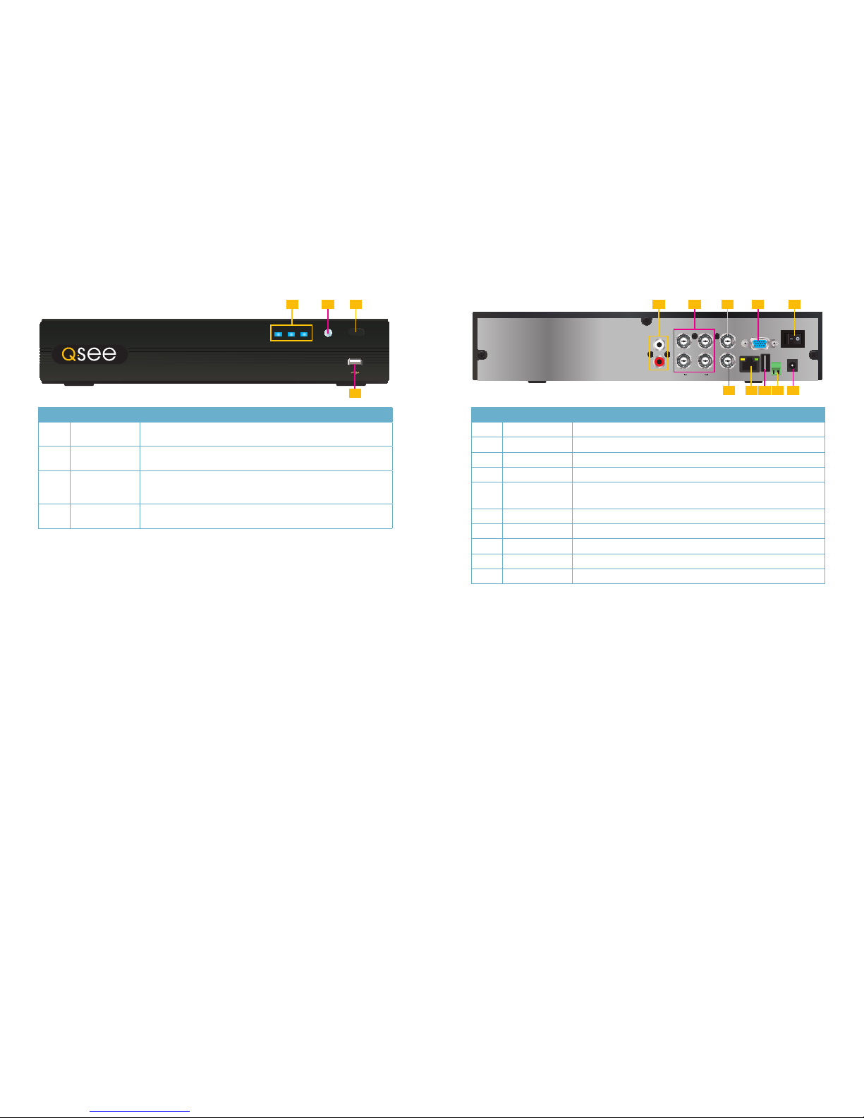
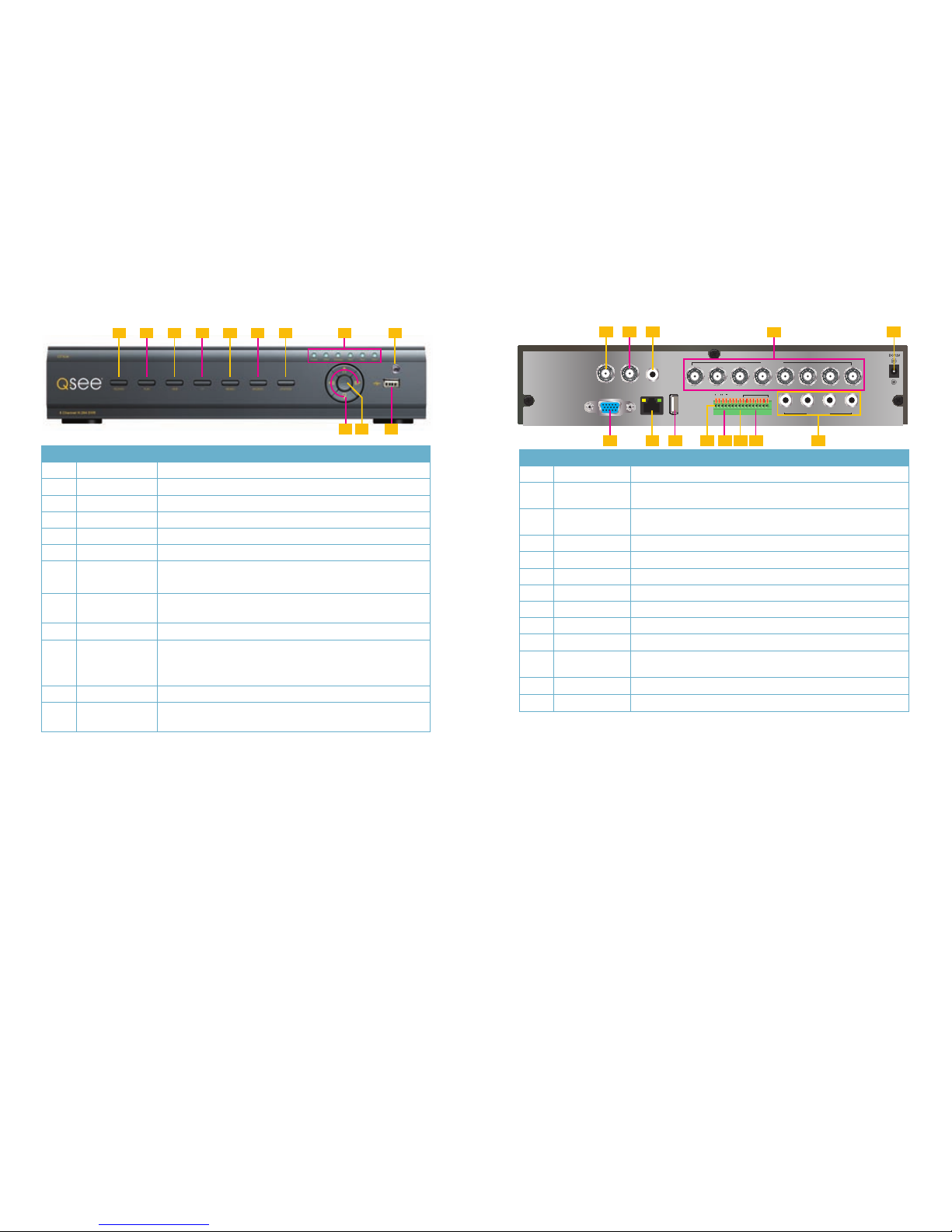
12 13
ITEM NAME FUNCTION
1
INDICATOR
LIGHTS
Shows the recording, network and power status of the DVR.
2
INFRARED
WINDOW
Receives signals from the remote control
3
VIDEO MODE
BUTTON
Press and hold 10 seconds (or until you hear a beep) to switch
video output from the VGA port (default) to the BNC video out
port.
4
USB PORT Used for external USB backup devices. The mouse will not
function in this port.
ITEM NAME FUNCTION
1
AUDIO IN 2 Channels of audio input
2
VIDEO IN Video input from up to 4 cameras
3
VIDEO OUT BNC connector for TV or monitor
4
VGA PORT VGA output for 19” or larger monitor
5
POWER
SWITCH
Use to turn on the DVR as well as to turn off after powering
down from within the GUI
6 AUDIO OUT BNC Audio output for amplified speaker
7 LAN Network (ethernet) port
8
USB PORT For the USB mouse
9 PTZ Connections for Pan-T ilt-Zoom speed dome cameras.
10
DC IN Power input for 12V DC power supply
FRONT PANEL
QT474
REAR PANEL
REC Net Power
TV/VGA
QT474
1 3
4
2
LAN
VGA
AUDIO IN
1
2
123
4
AUDIO OUT
VIDEO OUT
VIDEO IN USB DC 12V
1 3
2
5
7
4
6
9
8 10
14 15
1 2
123 4 5 6 7 8 9 1110
FRONT PANEL
VGA
SPOT
DC 12V
VIDEO OUT
VIDEO IN
1 3 5 7 9 11 13 15
2 4 6 8 10 12 14 16
USB
NET
ALARM OUT
P/Z
Y Z A 1 3 5 7 9 11 13 15
2 4 6 8 10 12 14 16
B
RS485
ALARM OUT
ALARM IN
1 2 3 4
K/B
GND
COMNOSV
2 3 41
8 9 10 11 12
5
6
7
13 14
REAR PANEL
QT426
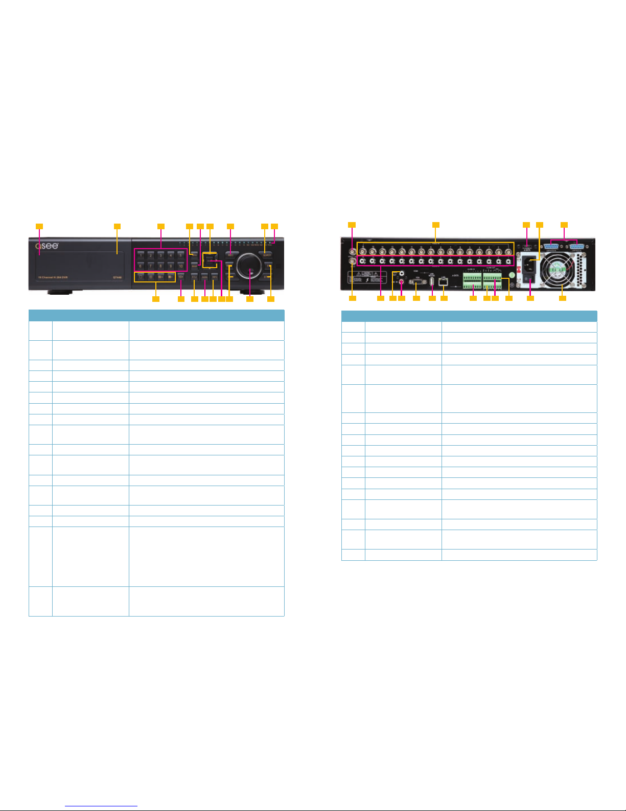
ITEM NAME FUNCTION
1
LED
INDICATORS
Show status of power, HDD, record, etc.
2
IR RECEIVER Receives signals from remote control
3 RECORD Manually begins recording
4 PLAY Launches PLAYBACK window
5 REW Rewind key
6 FF Fast Forward
7 +/MENU Increase the value in SETUP/Enter menu in LIVE VIEW
8 -/BACKUP Decrease the value in SETUP/Enter backup mode in LIVE VIEW
9 STOP/ESC Quit PLAYBACK mode/Exit the current window or status
Also switches video output mode.
10 ENTER Confirm selection
11 DIRECTION/
MULTISCREEN
1. Navigate through on-screen options
2. Change screen display mode between 1, 4, 9 and 16
channels
12 USB USB port to connect USB flash or external hard drives to
update firmware or back up recordings
ITEM NAME FUNCTION
1
AUDIO
OUTPUT
Connection for audio output – connect to an amplified speaker
2
AUDIO IN 4-Channel audio input for cameras equipped with audio
3
VGA PORT Video output for connecting to monitor
4
VIDEO OUT Video output for connecting to TV (BNC) or monitor
5 RS485 Connect to Pan-Tilt-Zoom camera to control motion
6 K/B Connect to keyboard
7
ALARM
OUTPUT
Output for alarm
8
+5 AND GND +5 and grounding
9
ALARM IN Connect to up to six exter nal sensors
10
USB PORT Connect USB mouse
11 NET Network (ethernet) port
12 SPOT Connect to another monitor as an auxiliary output channel. This
monitor will only display video and will have no menu access.
13
VIDEO IN Video input from up to 16 cameras
14
DC +12V Power input
16 17
1 2 3 4 5 6 7 8 9
10 1211
FRONT PANEL
Y Z
RS485
1 2 3 4 5 6 7 8
AUDIO IN
AUDIO
OUT
VIDEO
OUT
SPOT
USBLANVGA
VIDEO IN
GND
GND
COM
NO
P/Z
A B
K/B
1 2 3 4 5 6 7 8
ALARM IN
1 2 3 4
2 3 5
4
1
6 7 8 9 10 11 12 13
REAR PANEL
QT428
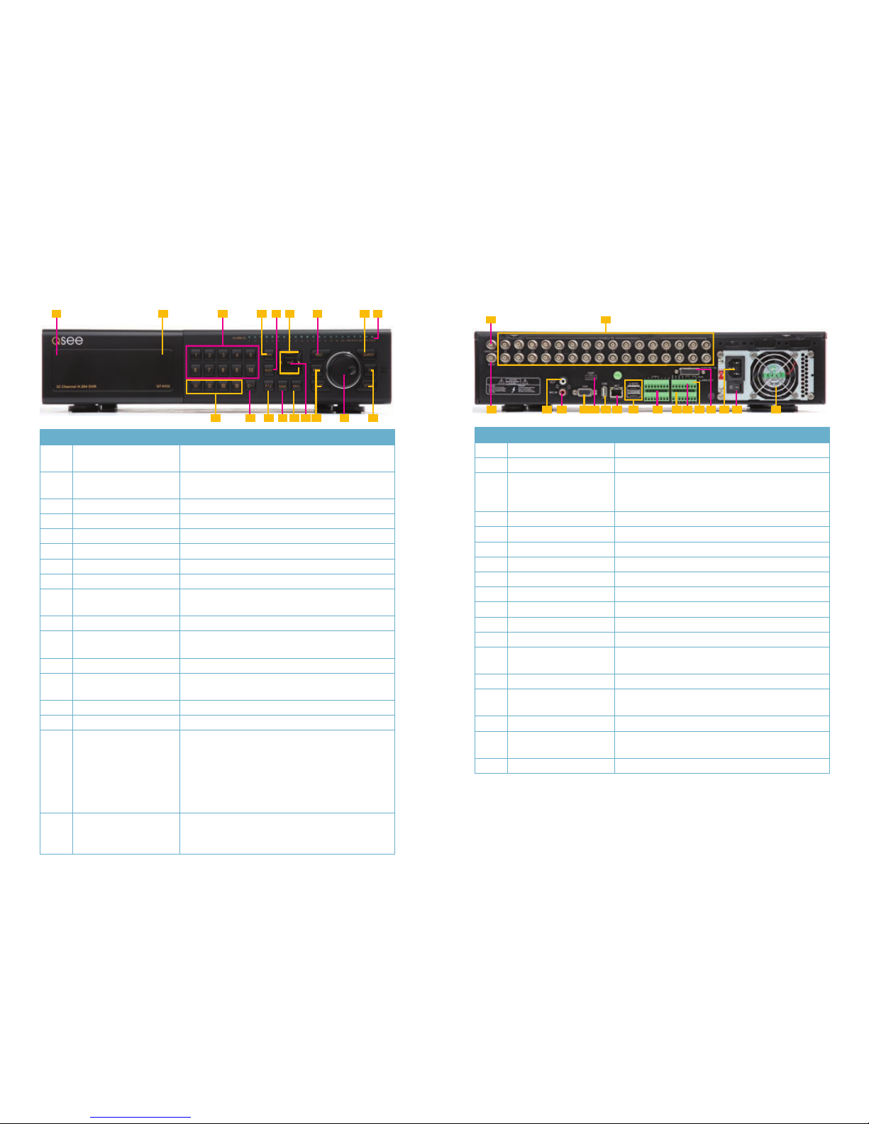
ITEM NAME FUNCTION
1 RECORD Manually begins recording
2 PLAY Launches PLAYBACK window
3 REW Rewind key
4 FF Fast Forward
5 +/MENU Increase the value in SETUP/Enter menu in LIVE VIEW
6 -/BACKUP Decrease the value in SETUP/Enter backup mode in LIVE VIEW
7 STOP/ESC Quit PLAYBACK mode/Exit the current window or status
Also switches video output mode.
8
LED
INDICATORS
Show status of power, HDD, record, etc.
9
IR RECEIVER Receives signals from remote control
10 DIRECTION/
MULTISCREEN
1. Navigate through on-screen options
2. Change screen display mode between 1, 4, 9 and 16
channels
11 ENTER Confirm selection
12 USB USB port to connect USB flash or external hard drives to
update firmware or back up recordings
ITEM NAME FUNCTION
1
VIDEO OUT Video output for connecting to TV (BNC) or monitor
2 SPOT Connect to another monitor as an auxiliary output channel. This
monitor will only display video and will have no menu access.
3
AUDIO
OUTPUT
Connection for audio output – connect to an amplified speaker
4
VIDEO IN Video input from up to 8 cameras
5
DC +12V Power input
6 VGA PORT Video output for connecting to monitor
7 LAN Network (ethernet) port
8
USB PORT Connect USB mouse
9 RS485 Connect to Pan-Tilt-Zoom camera to control motion
10 K/B Connect to keyboard
11
ALARM
OUTPUT
Output for alarm
12
ALARM IN Connect to up to eight exter nal sensors
13
AUDIO IN 4-Channel audio input for cameras equipped with audio
18 19
QT446
FRONT PANEL
ITEM NAME FUNCTION
1
POWER (Behind flip-down
panel)
Puts the DVR into standby mode or wakes it up from
standby mode.
2
USB PORT
(Behind flip-down panel)
Used for external USB backup devices. The mouse
will not function in this port.
3
NUMBER PAD Enter channel numbers.
4
MENU Opens the Main Menu
5
BACKUP Opens Backup Menu
6 DIRECTION Navigates through selections in menus
7
RECORD Begins manually recording on all channels
8
SEARCH Enters Search Mode
9
INDICATOR LIGHTS Shows status of the DVR Functions and the Hard
Drive
10
VIEWING MODE Change between 1, 4, 8 and 16-screen viewing mode
11
10+ BUTTON Input channels numbers above 10 by pushing this
button followed by the second digit.
12
PTZ Enter PTZ mode in live view
13
AUDIO Turn audio on or off in live view if audio input devices
are attached.
14
INFO Displays system information
15
ENTER Confirms selection in menus or input in fields
16
PLAYBACK CONTROLS REW - Rewind
PLAY - Opens the Playback interface. Pauses or
resumes playback
FF - Fast Forward
STOP - Quits Playback mode
Also switches video output mode.
17
CONTROL KNOB Outer ring navigates through menus
Inner knob increases or decreases speed of fast
forward or rewind.
3 5 7
4
1
2 6
9
8
10 11 12 14 1613 1715 16
BACK PANEL
1
2 4
6 987 10 11 1412 17161513 18
53
ITEM NAME FUNCTION
1
VIDEO OUT BNC connector for TV or monitor
2
VIDEO IN BNC connectors for up to 16 cameras
3
eSATA (2) Connection for external eSATA hard drive for backup
4
POWER SOCKET Attachment point for power cord
5 LOOP OUT (2) Output each channel to a separate monitor. Each port
handles 8 channels.
6
SPOT OUT Connect to another monitor as an auxiliary output
channel. This monitor will only display video and will
have no menu access.
7
AUDIO IN 16 channels of audio input
8
AUDIO OUT Audio output for amplified speaker
9
MICROPHONE IN Connect a microphone
10
VGA PORT VGA output for 19” or larger monitor
11
USB PORT For the USB mouse
12 LAN Network (ethernet) port
13
ALARM IN Connect up to 16 external sensors
14
ALARM OUT 4 Channel relay output for external alarms
15 PTZ Connections for Pan-Tilt-Zoom speed dome cameras.
Y = “+” Z = “-”
16 K/B Connector for a PTZ keyboard
17
POWER SWITCH Use to turn on the DVR as well as to tur n off after
powering down from within the GUI
18 FAN Cooling fan exhaust port. This should not be blocked.
20 21
QT4332
FRONT PANEL
ITEM NAME FUNCTION
1
POWER (Behind flip-down
panel)
Puts the DVR into standby mode or wakes it up from
standby mode.
2
USB PORT
(Behind flip-down panel)
Used for external USB backup devices. The mouse
will not function in this port.
3
NUMBER PAD Enter channel numbers.
4
MENU Opens the Main Menu
5
BACKUP Opens Backup Menu
6 DIRECTION Navigates through selections in menus
7
RECORD Begins manually recording on all channels
8
SEARCH Enters Search Mode
9
INDICATOR LIGHTS Shows status of the DVR Functions and the Hard
Drive
10
VIEWING MODE Change between 1, 4, 8 and 16-screen viewing mode
11
10+ BUTTON Input channels numbers above 10 by pushing this
button followed by the second digit.
12
PTZ Enter PTZ mode in live view
13
AUDIO Turn audio on or off in live view if audio input devices
are attached.
14
INFO Displays system information
15
ENTER Confirms selection in menus or input in fields
16
PLAYBACK CONTROLS REW - Rewind
PLAY - Opens the Playback interface. Pauses or
resumes playback
FF - Fast Forward
STOP - Quits Playback mode
Also switches video output mode.
17
CONTROL KNOB Outer ring navigates through menus
Inner knob increases or decreases speed of fast
forward or rewind.
3 5 7
4
1
2 6
9
8
10 11 12 14 1613 1715 16
BACK PANEL
ITEM NAME FUNCTION
1
VIDEO OUT BNC connector for TV or monitor
2
VIDEO IN BNC connectors for up to 32 cameras
3
SPOT OUT Connect to another monitor as an auxiliary output
channel. This monitor will only display video and will
have no menu access.
4 AUDIO OUT Audio output for amplified speaker
5
MICROPHONE IN Connect a microphone
6
VGA PORT VGA output for 19” or larger monitor
7 HDMI HDMI video output
8
USB PORT For the USB mouse
9 LAN Network (ethernet) port
10
eSATA (2) Connection for external eSATA hard drive for backup
11 ALARM IN Connect up to 16 external sensors
12
ALARM OUT 4 Channel relay output for external alarms
13 PTZ Connections for Pan-Tilt-Zoom speed dome cameras.
Y = “+” Z = “-”
14 K/B Connector for a PTZ keyboard
15
AUDIO IN Attachment point for audio dongle which allows up to
16 channels of audio input.
16
POWER SOCKET Attachment point for power cord
17
POWER SWITCH Use to turn on the DVR as well as to tur n off after
powering down from within the GUI
18 FAN Cooling fan exhaust port. This should not be blocked.
1
2
3 54 6 7 8 9 12 181413 161510 11 17
 Loading...