

Page 1

MVI71-MNET
PLC Platform
Modbus TCP/IP Interface Module
June 23, 2009
USER MANUAL
Page 2

MVI (Multi Vendor Interface) Modules
WARNING - EXPLOSION HAZARD - DO NOT DISCONNECT EQUIPMENT UNLESS POWER HAS BEEN
SWITCHED OFF OR THE AREA IS KNOWN TO BE NON-HAZARDOUS.
AVERTISSEMENT - RISQUE D'EXPLOSION - AVANT DE DÉCONNECTER L'EQUIPMENT, COUPER LE
COURANT OU S'ASSURER QUE L'EMPLACEMENT EST DÉSIGNÉ NON DANGEREUX.
CL I Div 2 GPs A, B, C, D
Temp Code T5
II 3 G
Ex nA IIC T5 X
0° C <= Ta <= 60° C
II - Equipment intended for above ground use (not for use in mines).
3 - Category 3 equipment, investigated for normal operation only.
G - Equipment protected against explosive gasses.
Important Installation Instructions
Power, Input and Output (I/O) wiring must be in accordance with Class I, Division 2 wiring methods, Article 501-4 (b)
of the National Electrical Code, NFPA 70 for installation in the U.S., or as specified in Section 18-1J2 of the Canadian
Electrical Code for installations in Canada, and in accordance with the authority having jurisdiction. The following
warnings must be heeded:
A WARNING - EXPLOSION HAZARD - SUBSTITUTION OF COMPONENTS MAY IMPAIR SUITABILITY FOR
CLASS I, DIV. 2;
B WARNING - EXPLOSION HAZARD - WHEN IN HAZARDOUS LOCATIONS, TURN OFF POWER BEFORE
REPLACING OR WIRING MODULES, and
C WARNING - EXPLOSION HAZARD - DO NOT DISCONNECT EQUIPMENT UNLESS POWER HAS BEEN
SWITCHED OFF OR THE AREA IS KNOWN TO BE NONHAZARDOUS.
D "THIS DEVICE SHALL BE POWERED BY CLASS 2 OUTPUTS ONLY.
Warnings
North America Warnings
A Warning - Explosion Hazard - Substitution of components may impair suitability for Class I, Division 2.
B Warning - Explosion Hazard - When in Hazardous Locations, turn off power before replacing or rewiring
modules.
Warning - Explosion Hazard - Do not disconnect equipment unless power has been switched off or the area is
known to be nonhazardous.
C Suitable for use in Class I, division 2 Groups A, B, C and D Hazardous Locations or Non-Hazardous Locations.
ATEX Warnings and Conditions of Safe Usage:
Power, Input, and Output (I/O) wiring must be in accordance with the authority having jurisdiction
A Warning - Explosion Hazard - When in hazardous locations, turn off power before replacing or wiring modules.
B Warning - Explosion Hazard - Do not disconnect equipment unless power has been switched off or the area is
known to be non-hazardous.
C These products are intended to be mounted in an IP54 enclosure. The devices shall provide external means to
prevent the rated voltage being exceeded by transient disturbances of more than 40%. This device must be used
only with ATEX certified backplanes.
D DO NOT OPEN WHEN ENERGIZED.
Page 3

Electrical Ratings
Backplane Current Load: 800 mA @ 5 V DC; 3mA @ 24V DC
Operating Temperature: 0 to 60°C (32 to 140°F)
Storage Temperature: -40 to 85°C (-40 to 185°F)
Shock: 30g Operational; 50g non-operational; Vibration: 5 g from 10 to 150 Hz
Relative Humidity 5% to 95% (non-condensing)
All phase conductor sizes must be at least 1.3 mm(squared) and all earth ground conductors must be at least
4mm(squared).
Markings
ANSI / ISA ISA 12.12.01 Class I Division 2, GPs A, B, C, D
CSA/cUL C22.2 No. 213-1987
CSA CB Certified IEC61010
ATEX EN60079-0 Category 3, Zone 2
EN60079-15
243333
Warning: This module is not hot-swappable! Always remove power from the rack before inserting or removing this
module, or damage may result to the module, the processor, or other connected devices.
Battery Life Advisory
All modules in the MVI series use a rechargeable Lithium Vanadium Pentoxide battery to backup the 512K SRAM
memory, real-time clock, and CMOS. The battery should last for the life of the module.
The module must be powered for approximately twenty hours before it becomes fully charged. After it is fully charged,
the battery provides backup power for the CMOS setup and configuration data, the real-time clock, and the 512K
SRAM memory for approximately 21 days.
Before you remove a module from its power source, ensure that the battery within the module is fully charged. A fully
charged battery will hold the BIOS settings (after being removed from its power source) for a limited number of days.
When the battery is fully discharged, the module will revert to the default BIOS settings.
Note: The battery is not user replaceable.
Your Feedback Please
We always want you to feel that you made the right decision to use our products. If you have suggestions, comments,
compliments or complaints about the product, documentation or support, please write or call us.
ProSoft Technology
5201 Truxtun Ave., 3rd Floor
Bakersfield, CA 93309
+1 (661) 716-5100
+1 (661) 716-5101 (Fax)
www.prosoft-technology.com
Copyright © ProSoft Technology, Inc. 2009. All Rights Reserved.
MVI71-MNET User Manual
June 23, 2009
ProSoft Technology ®, ProLinx ®, inRAx ®, ProTalk®, and RadioLinx ® are Registered Trademarks of ProSoft
Technology, Inc. All other brand or product names are or may be trademarks of, and are used to identify products
and services of, their respective owners.
Page 4

ProSoft Technology® Product Documentation
In an effort to conserve paper, ProSoft Technology no longer includes printed manuals with our product shipments.
User Manuals, Datasheets, Sample Ladder Files, and Configuration Files are provided on the enclosed CD, and are
available at no charge from our web site: www.prosoft-technology.com
Printed documentation is available for purchase. Contact ProSoft Technology for pricing and availability.
Asia Pacific: +603.7724.2080
Europe, Middle East, Africa: +33 (0) 5.3436.87.20
Latin America: +1.281.298.9109
North America: +1.661.716.5100
Page 5

Contents MVI71-MNET ♦ PLC Platform
User Manual Modbus TCP/IP Interface Module
Contents
MVI (Multi Vendor Interface) Modules ................................................................................................2
Important Installation Instructions.......................................................................................................2
Warnings.............................................................................................................................................2
Battery Life Advisory...........................................................................................................................3
Your Feedback Please........................................................................................................................3
ProSoft Technology® Product Documentation...................................................................................4
Guide to the MVI71-MNET User Manual 7
1 Start Here 9
1.1 System Requirements...............................................................................................9
1.2 Package Contents...................................................................................................10
1.3 Install ProSoft Configuration Builder Software........................................................11
1.4 Setting Jumpers ......................................................................................................12
1.5 Install the Module in the Rack.................................................................................12
1.6 Connect your PC to the Processor..........................................................................14
1.7 Download the Sample Program to the Processor...................................................15
1.8 Connect your PC to the Module..............................................................................18
2 Module Configuration 19
2.1 Installing and Configuring the Module.....................................................................19
2.2 Module Data............................................................................................................22
2.3 Status Data..............................................................................................................22
2.4 User Data ................................................................................................................22
2.5 Event Command Data.............................................................................................23
2.6 Modbus Message Data ...........................................................................................23
2.7 ProSoft Configuration Builder..................................................................................23
2.8 Download the Project to the Module.......................................................................40
3 Ladder Logic 41
4 Diagnostics and Troubleshooting 43
4.1 Reading Status Data from the Module....................................................................43
4.2 LED Status Indicators..............................................................................................53
5 Reference 57
5.1 Product Specifications.............................................................................................57
5.2 Functional Overview................................................................................................59
5.3 Cable Connections..................................................................................................78
5.4 MVI71-MNET Status Data Definition for Side Connect File....................................82
5.5 Status Data Structure for Database Storage...........................................................83
5.6 Client Error/Status Data ..........................................................................................85
ProSoft Technology, Inc. Page 5 of 109
June 23, 2009
Page 6

MVI71-MNET ♦ PLC Platform Contents
Modbus TCP/IP Interface Module User Manual
5.7 Modbus Protocol Specification ............................................................................... 88
6 Support, Service & Warranty 99
6.1 How to Contact Us: Technical Support................................................................... 99
6.2 Return Material Authorization (RMA) Policies and Conditions............................. 100
6.3 LIMITED WARRANTY.......................................................................................... 101
Index 107
Page 6 of 109 ProSoft Technology, Inc.
June 23, 2009
Page 7

Start Here MVI71-MNET ♦ PLC Platform
User Manual Modbus TCP/IP Interface Module
Guide to the MVI71-MNET User Manual
Function Section to Read Details
Introduction
(Must Do)
Verify Communication,
Diagnostic and
Troubleshooting
Reference
Product Specifications
Functional Overview
Support, Service, and
Warranty
Index
→
→
→
→
Start Here (page 9)
Verifying
Communication
(page 53)
Diagnostics and
Troubleshooting
(page
43)
Reference (page 57)
Functional Overview
(page 59)
Product
Specifications (page
57)
Support, Service
and Warranty (page
99)
This Section introduces the customer to the
module. Included are: package contents,
system requirements, hardware installation, and
basic configuration.
This section describes how to verify
communications with the network. Diagnostic
and Troubleshooting procedures.
These sections contain general references
associated with this product, Specifications, and
the Functional Overview.
This section contains Support, Service and
Warranty information.
Index of chapters.
ProSoft Technology, Inc. Page 7 of 109
June 23, 2009
Page 8

MVI71-MNET ♦ PLC Platform Start Here
Modbus TCP/IP Interface Module User Manual
Page 8 of 109 ProSoft Technology, Inc.
June 23, 2009
Page 9

Start Here MVI71-MNET ♦ PLC Platform User Manual Modbus TCP/IP Interface Module
1 Start Here
In This Chapter
System Requirements.............................................................................9
Package Contents.................................................................................10
Install ProSoft Configuration Builder Software.......................................11
Setting Jumpers ....................................................................................12
Install the Module in the Rack ...............................................................12
Connect your PC to the Processor........................................................14
Download the Sample Program to the Processor..................................15
Connect your PC to the Module ............................................................18
To get the most benefit from this User Manual, you should have the following
skills:
Rockwell Automation® RSLogix™ software: launch the program,
configure ladder logic, and transfer the ladder logic to the processor
Microsoft Windows: install and launch programs, execute menu commands,
navigate dialog boxes, and enter data.
Hardware installation and wiring: install the module, and safely connect
Modbus TCP/IP and PLC devices to a power source and to the MVI71-MNET
module’s application ports.
Caution: You must be able to complete the application without exposing personnel or
equipment to unsafe or inappropriate working conditions.
1.1 System Requirements
The MVI71-MNET module requires the following minimum hardware and
software components:
Rockwell Automation PLC processor, with compatible power supply and one
free slot in the rack, for the MVI71-MNET module. The module requires
800mA of available power.
The PLC Processor must provide for at least 64 words of BTR/BTW area,
otherwise the module may not function correctly.
Rockwell Automation RSLogix 5 programming software.
Rockwell Automation RSLinx communication software
Pentium® 100 MHz minimum. Pentium III 700 MHz (or better) recommended
ProSoft Technology, Inc. Page 9 of 109
June 23, 2009
Page 10

MVI71-MNET ♦ PLC Platform Start Here
Modbus TCP/IP Interface Module User Manual
Supported operating systems:
o Microsoft Windows XP
o Microsoft Windows 2000
o Microsoft Windows NT v4.0 with Service Pack 3 or greater
o Microsoft Windows ME
o Microsoft Windows 98
64 Mbytes of RAM minimum, 256 Mbytes of RAM recommended
100 Mbytes of free hard disk space (or more based on application
requirements)
256-color VGA graphics adapter, 800 x 600 minimum resolution (True Color
1024 × 768 recommended)
CD-ROM drive
HyperTerminal or other terminal emulator program capable of file transfers
using Zmodem protocol.
1.2 Package Contents
The following components are included with your MVI71-MNET module, and are
all required for installation and configuration.
Important: Before beginning the installation, please verify that all of the following items are
present.
Qty. Part Name Part Number Part Description
1
1 Cable
1 Cable
1
MVI71-MNET
Module
inRAx
Solutions CD
MVI71-MNET Modbus TCP/IP Interface Module
Cable #15, RS232
Null Modem
RJ45 to DB9 Male
Adapter
For RS232 Connection to the CFG Port
For DB9 Connection to Module’s Port
Contains sample programs, utilities and
documentation for the MVI71-MNET module.
If any of these components are missing, please contact ProSoft Technology
Support for replacement parts.
Page 10 of 109 ProSoft Technology, Inc.
June 23, 2009
Page 11

Start Here MVI71-MNET ♦ PLC Platform
User Manual Modbus TCP/IP Interface Module
1.3 Install ProSoft Configuration Builder Software
You must install the ProSoft Configuration Builder (PCB) software in order to
configure the module. You can always get the newest version of ProSoft
Configuration Builder from the ProSoft Technology web site.
To install ProSoft Configuration Builder from the ProSoft Web Site
1 Open your web browser and navigate to http://www.prosoft-
technology.com/pcb
2 Click the D
Configuration Builder.
3 Choose "S
4 Save the file to your Desktop, so that you can find it easily when you have
finished downloading.
5 When the download is complete, locate and open the file, and then follow the
instructions on your screen to install the program.
If you do not have access to the Internet, you can install ProSoft Configuration
Builder from the ProSoft Solutions CD-ROM, included in the package with your
module.
To install ProSoft Configuration Builder from the Product CD
1 Insert the ProSoft Solutions Product CD into the CD drive of your PC. Wait for
the startup screen to appear.
2 On the startup screen, click P
explorer window.
3 Click to open the U
and files you will need to set up and configure your module.
4 Double-click the S
"PCB_*.
software on your PC. The information represented by the "*" character in the
file name is the PCB version number and, therefore, subject to change as
new versions of PCB are released.
OWNLOAD HERE link to download the latest version of ProSoft
AVE" or "SAVE FILE" when prompted.
RODUCT DOCUMENTATION. This action opens an
TILITIES folder. This folder contains all of the applications
ETUPCONFIGURATIONTOOL folder, double-click the
EXE" file and follow the instructions on your screen to install the
Note: Many of the configuration and maintenance procedures use files and other utilities on the
CD-ROM. You may wish to copy the files from the Utilities folder on the CD-ROM to a convenient
location on your hard drive.
ProSoft Technology, Inc. Page 11 of 109
June 23, 2009
Page 12
MVI71-MNET ♦ PLC Platform Start Here
Modbus TCP/IP Interface Module User Manual
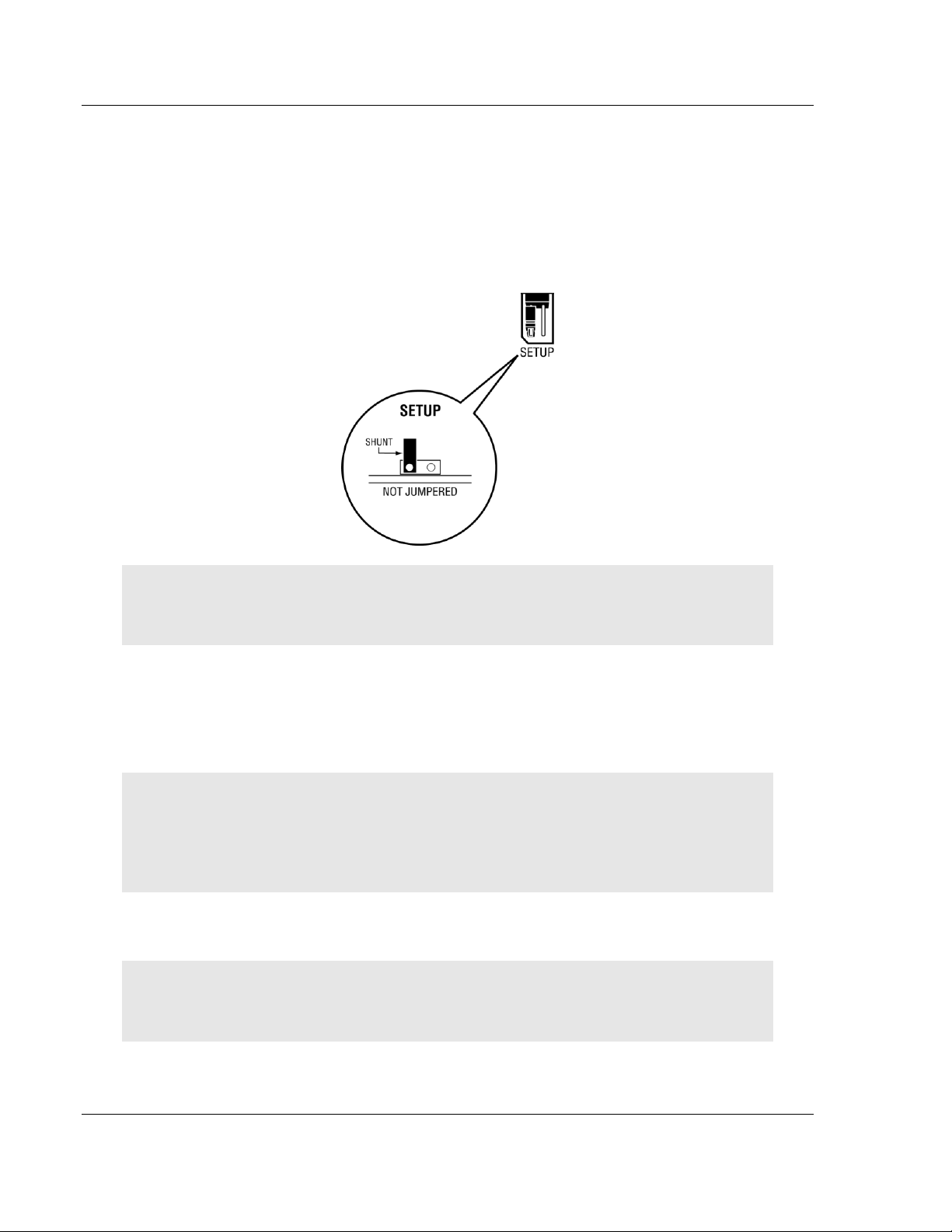
1.4 Setting Jumpers
The Setup Jumper acts as "write protection" for the module’s flash memory. In
"write protected" mode, the Setup pins are not connected, and the module’s
firmware cannot be overwritten. Do not jumper the Setup pins together unless
you are directed to do so by ProSoft Technical Support.
The following illustration shows the MVI71-MNET jumper configuration.
Note: If you are installing the module in a remote rack, you may prefer to leave the Setup pins
jumpered. That way, you can update the module’s firmware without requiring physical access to
the module.
1.5 Install the Module in the Rack
If you have not already installed and configured your PLC processor and power
supply, please do so before installing the MVI71-MNET module. Refer to your
Rockwell Automation product documentation for installation instructions.
Warning: You must follow all safety instructions when installing this or any other electronic
devices. Failure to follow safety procedures could result in damage to hardware or data, or even
serious injury or death to personnel. Refer to the documentation for each device you plan to
connect to verify that suitable safety procedures are in place before installing or servicing the
device.
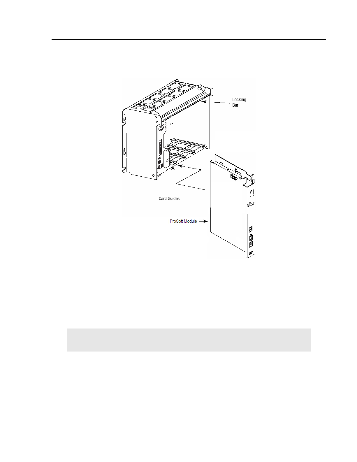
After you have checked the placement of the jumpers, insert MVI71-MNET into
the PLC™ chassis. Use the same technique recommended by Rockwell
Automation to remove and install PLC modules.
Warning: This module is not hot-swappable! Always remove power from the rack before
inserting or removing this module, or damage may result to the module, the processor, or other
connected devices.
Page 12 of 109 ProSoft Technology, Inc.
June 23, 2009
Page 13
Start Here MVI71-MNET ♦ PLC Platform
User Manual Modbus TCP/IP Interface Module
1 Turn power OFF.
2 Align the module with the top and bottom guides, and slide it into the rack
until the module is firmly against the backplane connector.
3 With a firm but steady push, snap the module into place.
4 Check that the holding clips on the top and bottom of the module are securely
in the locking holes of the rack.
5 Make a note of the slot location. You will need to identify the slot in which the
module is installed in order for the sample program to work correctly. Slot
numbers are identified on the green circuit board (backplane) of the PLC
rack.
6 Turn power ON.
Note: If you insert the module improperly, the system may stop working, or may behave
unpredictably.
ProSoft Technology, Inc. Page 13 of 109
June 23, 2009
Page 14
MVI71-MNET ♦ PLC Platform Start Here
Modbus TCP/IP Interface Module User Manual
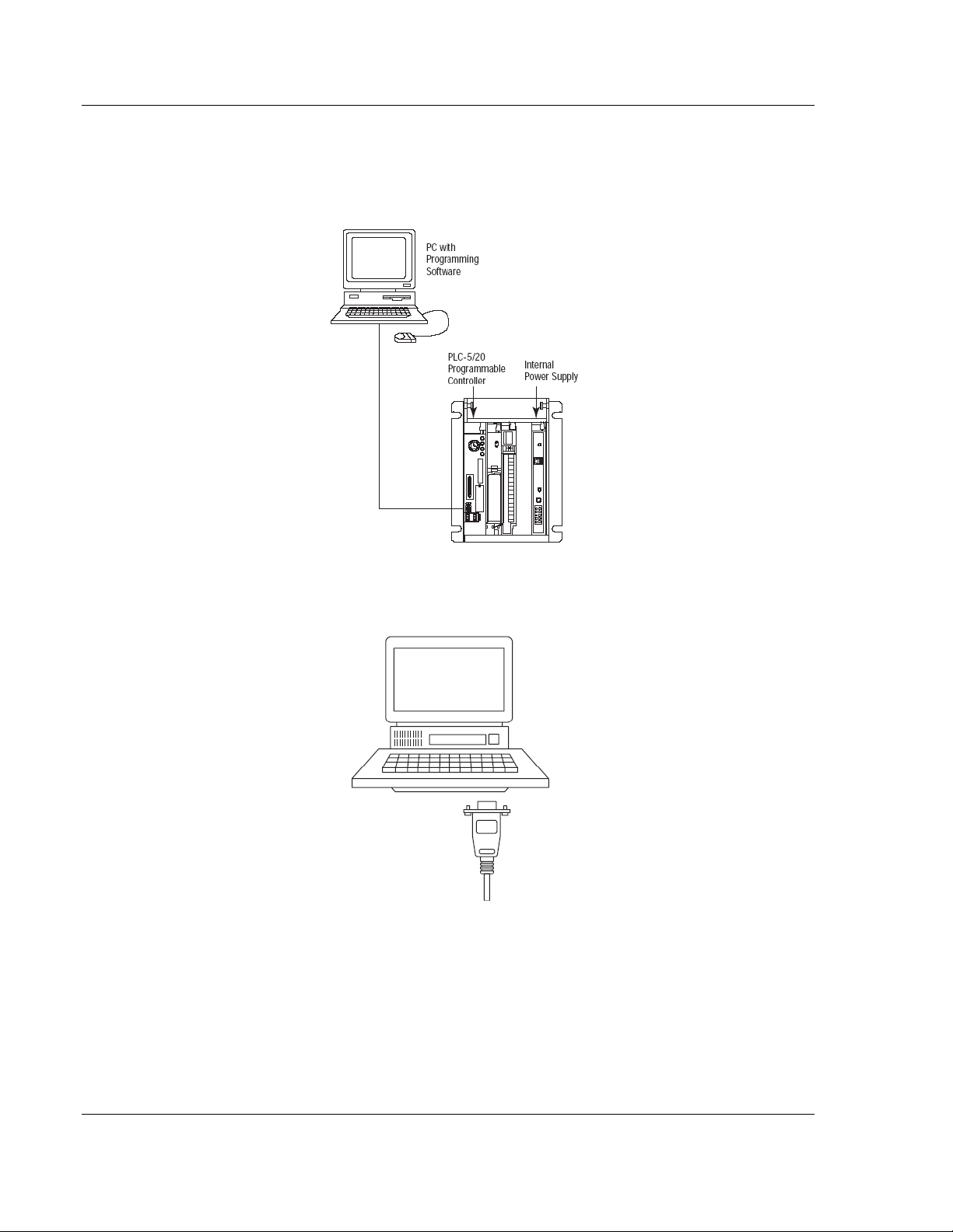
1.6 Connect your PC to the Processor
1 Connect the right-angle connector end of the cable to your controller at the
communications port.
2 Connect the straight connector end of the cable to the serial port on your
computer.
Page 14 of 109 ProSoft Technology, Inc.
June 23, 2009
Page 15
Start Here MVI71-MNET ♦ PLC Platform
User Manual Modbus TCP/IP Interface Module
1.7 Download the Sample Program to the Processor
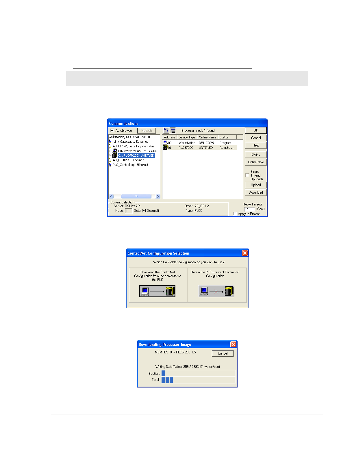
To download the sample program from RSLogix 5 to the PLC processor:
Note: The key switch on the front of the PLC processor must be in the REM position.
1 If you are not already online to the processor, open the Communications
menu, and then choose Download. RSLogix will establish communication
with the processor.
2 Click the Download button to transfer the sample program to the processor.
3 When prompted, choose Computer to PLC
4 RSLogix will compile the program and transfer it to the processor. This
process may take a few minutes.
ProSoft Technology, Inc. Page 15 of 109
June 23, 2009
Page 16
MVI71-MNET ♦ PLC Platform Start Here
Modbus TCP/IP Interface Module User Manual
5 When the download is complete, RSLogix will open another confirmation
dialog box. Click OK to switch the processor from Program mode to Run
mode.
Note: If you receive an error message during these steps, refer to your RSLogix documentation to
interpret and correct the error.
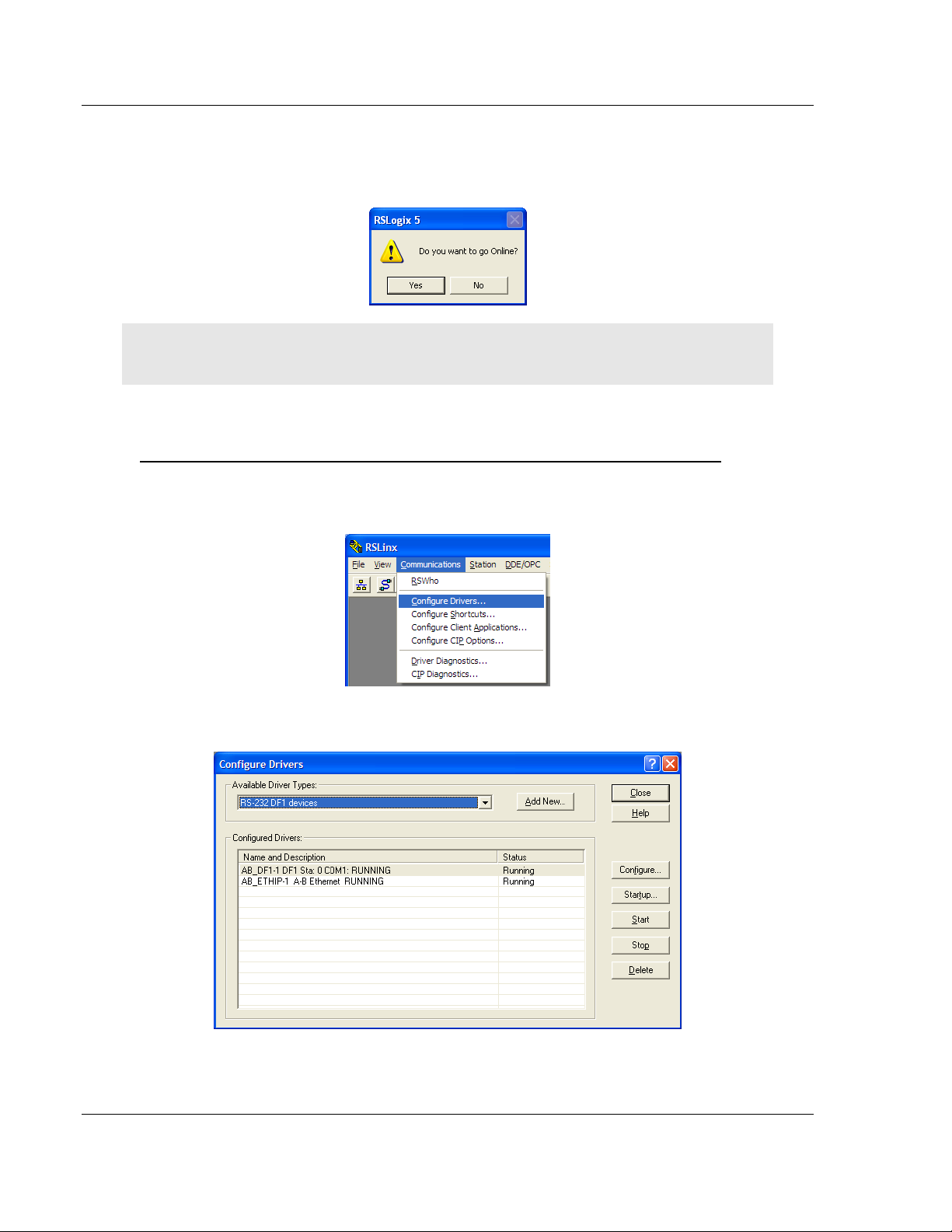
1.7.1 Configuring the RSLinx Driver for the PC COM Port
If RSLogix is unable to establish communication with the processor, follow these steps
1 Open RSL
2 Open the C
INX.
OMMUNICATIONS menu, and choose CONFIGURE DRIVERS.
This action opens the C
ONFIGURE DRIVERS dialog box.
Page 16 of 109 ProSoft Technology, Inc.
June 23, 2009
Page 17
Start Here MVI71-MNET ♦ PLC Platform
User Manual Modbus TCP/IP Interface Module
Note: If the list of configured drivers is blank, you must first choose and configure a driver from the
Available Driver Types list. The recommended driver type to choose for serial communication with
the processor is RS-232 DF1 DEVICES.
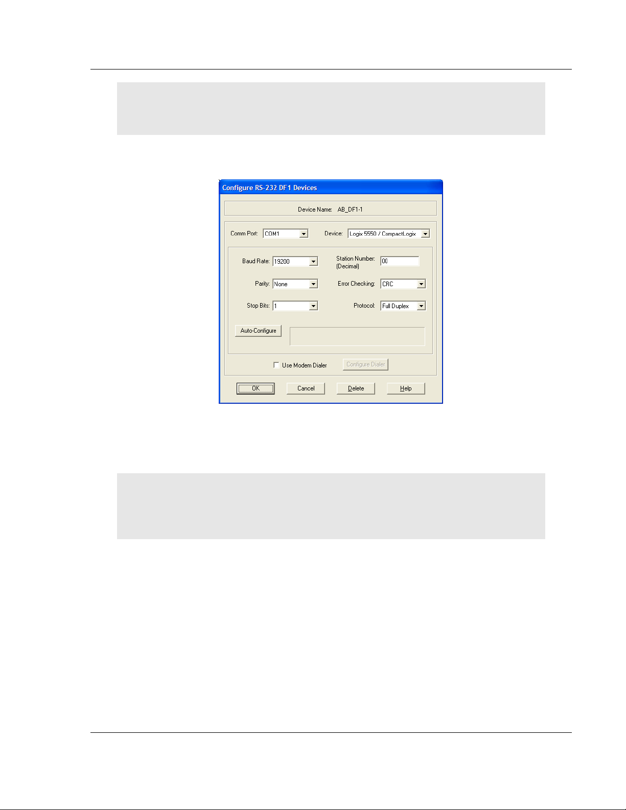
3 Click to select the driver, and then click CONFIGURE. This action opens the
C
ONFIGURE ALLEN-BRADLEY DF1 COMMUNICATIONS DEVICE dialog box.
4 Click the A
UTO-CONFIGURE button. RSLinx will attempt to configure your
serial port to work with the selected driver.
5 When you see the message A
UTO CONFIGURATION SUCCESSFUL, click the OK
button to dismiss the dialog box.
Note: If the auto-configuration procedure fails, verify that the cables are connected correctly
between the processor and the serial port on your computer, and then try again. If you are still
unable to auto-configure the port, refer to your RSLinx documentation for further troubleshooting
steps.
ProSoft Technology, Inc. Page 17 of 109
June 23, 2009
Page 18

MVI71-MNET ♦ PLC Platform Start Here
Modbus TCP/IP Interface Module User Manual
1.8 Connect your PC to the Module
With the module securely mounted, connect your PC to the Configuration/Debug
port using an RJ45-DB-9 Serial Adapter Cable and a Null Modem Cable.
1 Attach both cables as shown.
2 Insert the RJ45 cable connector into the Configuration/Debug port of the
module.
3 Attach the other end to the serial port on your PC.
Page 18 of 109 ProSoft Technology, Inc.
June 23, 2009
Page 19

Module Configuration MVI71-MNET ♦ PLC Platform User Manual Modbus TCP/IP Interface Module
2 Module Configuration
In This Chapter
Installing and Configuring the Module ...................................................19
Module Data..........................................................................................22
Status Data............................................................................................22
User Data..............................................................................................22
Event Command Data...........................................................................23
Modbus Message Data..........................................................................23
ProSoft Configuration Builder................................................................23
Download the Project to the Module......................................................40
This section contains the setup procedure, data, and ladder logic for successful
application of the MVI71-MNET module. Each step in the setup procedure is
defined in order to simplify the use of the module. Set up for the module for both
the BTR/BTW and side-connect interfaces is covered.
2.1 Installing and Configuring the Module
This chapter describes how to install and configure the module to work with your
application. The configuration process consists of the following steps.
1 Modify the module’s configuration files to meet the needs of your application,
and copy the updated configuration to the module. Example configuration
files are provided on the CD-ROM. Refer to the Modifying the Example
Configuration File section, later in this chapter, for more information on the
configuration files.
2 Modify the example ladder logic to meet the needs of your application, and
copy the ladder logic to the processor. Example ladder logic files are provided
on the CD-ROM.
Note: If you are installing this module in an existing application, you can copy the necessary
elements from the example ladder logic into your application.
The rest of this chapter describes these steps in more detail.
It is now time to edit the MNET.CFG file to set up the module for the specific
application. Refer to the Configuration File section of this document. Download
this configuration to the module along with the associated ladder logic.
ProSoft Technology, Inc. Page 19 of 109
June 23, 2009
Page 20

MVI71-MNET ♦ PLC Platform Module Configuration
Modbus TCP/IP Interface Module User Manual
The next step in installing and configuring the module is to define whether the
block transfer or side-connect interface will be utilized. If the block transfer
interface is to be used you should be ready to connect the module to the Modbus
TCP/IP network if the ladder logic is defined correctly.
If the side-connect interface is utilized, make sure the file SC_DATA.TXT on the
Compact Flash Disk contains the correct first file number. You can run the
setdnpsc.exe program to set the file number to be used with your application.
Install the module in the rack and turn on the power. Connect the serial cable to
the module’s debug/configuration port and exit the program by pressing [E
SC][X].
This will cause the program to exit and remain at the operating system prompt.
Run the setdnpsc.exe program with a command line argument of the file number
to use for the first file. For example, to select N10: as the first file, enter the
following:
SETDNPSC 10
The program will build the SC_DATA.TXT on the Compact Flash Disk (C: drive in
the root directory).
Next, define the data files to be used with the application. If the block transfer
interface is used, define the data files to hold the user data (read and write data).
Enter the ladder logic to handle the blocks transferred between the module and
the PLC. Download the program to the PLC and test the program with the
module.
If the side-connect interface is used, no ladder logic is required for data transfer.
The user data files to interface with the module must reside in contiguous order
in the processor. The first file to be used by the interface is the status/control file.
This is file number set in the SC_DATA.TXT file using the SETDNPSC.EXE
program. The following table lists the files used by the side-connect interface:
File Number Example Size Description
Cfg File N10 200 Control/Status File
Cfg File+1 N11 to 1000 Data transferred from the module to the processor
Other files for read data
Cfg File+1+n N12 to 1000 Data transferred from the processor to the module
Cfg File+1+n+m Other files for write data
n is the number of read data files minus one. Each file contains up to 1000
words.
m is the number of write data files minus one. Each file contains up to 1000
words.
More than one read and/or write file may exist in an application. This is required
when more than 1000 words of data are required. Two examples are given below
for the files used with different data set sizes:
Page 20 of 109 ProSoft Technology, Inc.
June 23, 2009
Page 21

Module Configuration MVI71-MNET ♦ PLC Platform
User Manual Modbus TCP/IP Interface Module
2.1.1 Example of 240 words of read and write data (cfg file=10)
Data Files Description
N11:0 to 239 Read data
N12:0 to 239 Write data
2.1.2 Example of 2300 read and 3500 write data registers (cfg
file=10)
Data Files Description
N11:0 to 999 Read data words 0 to 999
N12:0 to 999 Read data words 1000 to 1999
N13:0 to 299 Read data words 2000 to 2299
N14:0 to 999 Write data words 0 to 999
N15:0 to 999 Write data words 1000 to 1999
N16:0 to 999 Write data words 2000 to 2999
N17:0 to 499 Write data words 3000 to 3499
Even if the files are not required for an application, they still are reserved and
should only be used for that purpose. The read and write data contained in the
last set of files possess the data transferred between the module and the
processor. The read data file (Cfg File + 1) will contain data transferred from the
module to the processor and should be associated with control data types. The
write data file (Cfg File + 1 + n) will contain data passed to the module from the
processor and should be associated with monitor data types.
Special care must be taken when defining the files for the side-connect interface.
Because the module directly interacts with the PLC processor and its memory,
any errors in the configuration may cause the processor to fault and it may even
lose its configuration and program. After defining the files and populating them
with the correct data, download the program to the processor, and place the
processor in run mode. If everything is configured correctly, the module should
start its normal operation.
The module is now set up and ready to be used with your application. Insert the
module in the rack (with the power turned off) and attach the serial
communication cables. Download the new application to the controller and place
the processor in run mode. Download the new MNET.CFG file to the module
using a terminal emulation program. If all the configuration parameters are set
correctly and the module is attached to a network, the module’s Application LED
(APP LED) should remain off and the backplane activity LED (BP ACT) should
blink very rapidly.
ProSoft Technology, Inc. Page 21 of 109
June 23, 2009
Page 22

MVI71-MNET ♦ PLC Platform Module Configuration
Modbus TCP/IP Interface Module User Manual
2.2 Module Data
All data related to the MVI71-MNET module is stored in a user defined data files.
It is the responsibility of the ladder logic programmer to construct all the data files
required by the program and to write the ladder logic required to interface to
these files.
2.3 Status Data
When the side-connect interface is employed in the application, the status data is
automatically transferred from the module to the first file used by the interface.
The data is placed at an offset of 0 in the file and has the format shown in the
Reference chapter.
When the block transfer interface is used, the status data is placed in the
module’s internal database at the location specified by the Error/Status Offset
parameter in the configuration file. If this data area is transferred to the processor
in the read data area, it will be passed from the module to the processor in a
normal BTR block. This will be placed in the normal read data area. The format
of the data is exactly the same as shown above, but the user determines its
position. Refer to the Reference chapter for a complete listing of the data stored
in this object.
2.4 User Data
When the side-connect interface is utilized, the read and write data is moved
between the module and the processor without any ladder logic. The size of the
data area and position of the data areas in the module’s database is determined
by the parameters set in the configuration file.
When the block transfer interface is used, ladder logic is required to page the
data between the module and the processor. The size of the data area and
position of the data areas in the module’s database is determined by the
parameters set in the configuration file.
The read data area should be set to match the value entered in the Read
Register Count parameter of the MNET.CFG file. For ease of use, this array
should be dimensioned as an even increment of 60 words. This data is paged up
to 60 words at a time from the module to the processor. The Read Data task is
responsible for placing the data received into the proper position in the read data
array. Use this data for status and control in the ladder logic of the processor.
The write data area should be set to match the value entered in the Write
Register Count parameter of the MNET.CFG file. For ease of use, this array
should be dimensioned as even increments of 60 words. This data is paged up to
60 words at a time from the processor to the module. The Write Data task is
responsible for placing the write data into the output image for transfer to the
module. This data is passed from the processor to the module for status and
control information for use in other nodes on the network.
Page 22 of 109 ProSoft Technology, Inc.
June 23, 2009
Page 23

Module Configuration MVI71-MNET ♦ PLC Platform
User Manual Modbus TCP/IP Interface Module
2.5 Event Command Data
A user file containing Event Command Data is only required when event
commands are utilized in the application. This file holds the information required
for an event command. An array of these objects should be defined and hold the
event command set to be employed in the application.
2.6 Modbus Message Data
This new version of the module’s program includes the pass-through mode. In
this mode, write messages sent to a slave port are passed directly through to the
processor. It is the responsibility of the ladder logic to process the message
received using this feature. If the side-connect interface is used, this data set will
be placed in the file selected in the SC_DATA.TXT file starting at register offset
50. Ladder logic is required to parse the message or data set received and to
place the data in the correct user data file.
If the block transfer interface is utilized, the pass-through messages will be
passed from the module to the processor in special control blocks. Ladder logic
is required to handle each block received and to place the data in the correct
user data file.
This information is passed from the module to the processor using a block
identification code of 9996 if the unformatted pass-through mode (code 1) is
selected. Word two of this block contains the length of the message and the
message starts at word 3. Other controller tags are required to store the
controlled values contained in these messages. The Modbus protocol supports
control of binary output (coils - functions 5 and 15) and registers (functions 6 and
16).
Additionally, formatted message blocks can be sent from the module to the
processor when the pass-through option is selected using the format selection
(codes 2 or 3 in the MNET.CFG file). These blocks require less decoding than
the unformatted blocks. Refer to the user manual for a full discussion on utilizing
the pass-through option in an application.
2.7 ProSoft Configuration Builder
ProSoft Configuration Builder (PCB) provides a quick and easy way to manage
module configuration files customized to meet your application needs. PCB is not
only a powerful solution for new configuration files, but also allows you to import
information from previously installed (known working) configurations to new
projects.
ProSoft Technology, Inc. Page 23 of 109
June 23, 2009
Page 24
MVI71-MNET ♦ PLC Platform Module Configuration
Modbus TCP/IP Interface Module User Manual
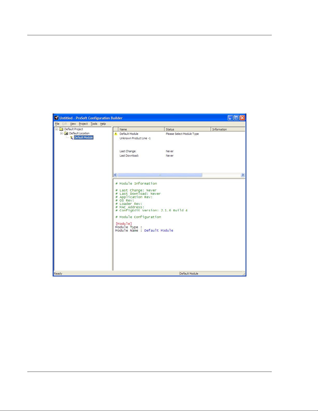
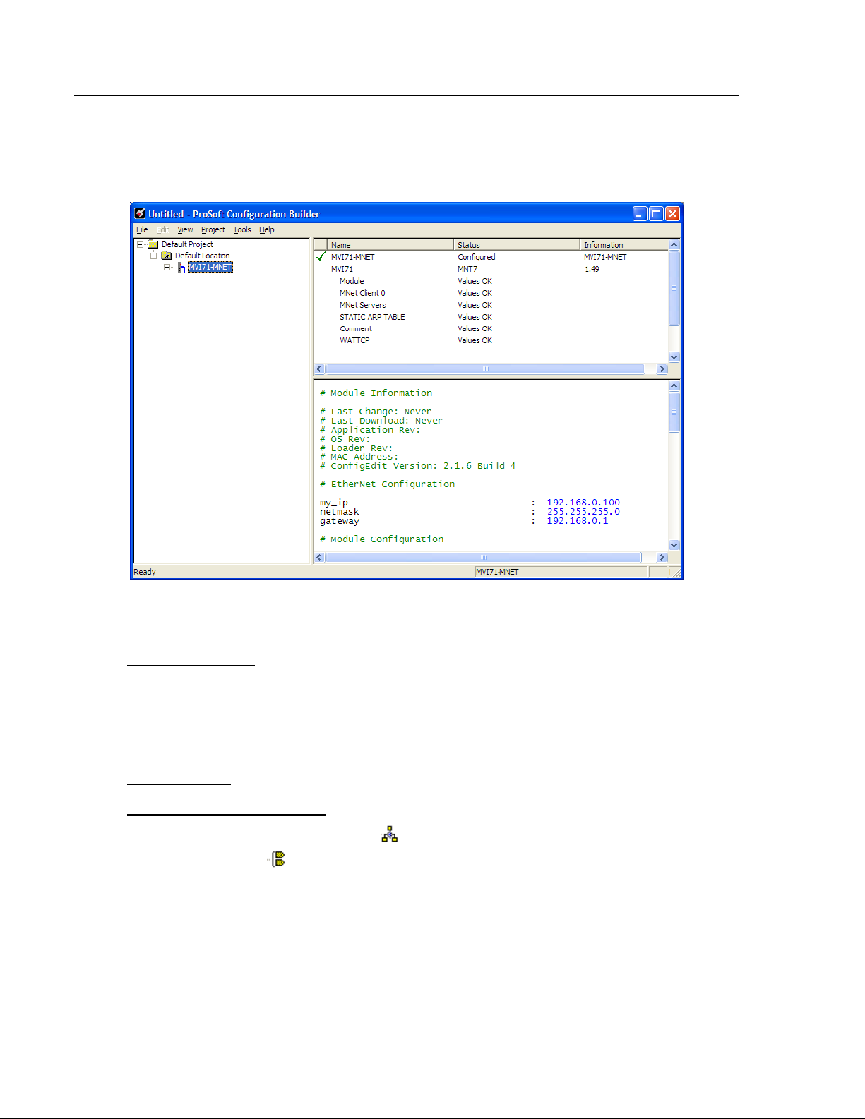
2.7.1 Set Up the Project
To begin, start ProSoft Configuration Builder. If you have used other Windows
configuration tools before, you will find the screen layout familiar. ProSoft
Configuration Builder’s window consists of a tree view on the left, an information
pane and a configuration pane on the right side of the window. When you first
start ProSoft Configuration Builder, the tree view consists of folders for Default
Project and Default Location, with a Default Module in the Default Location
folder. The following illustration shows the ProSoft Configuration Builder window
with a new project.
Page 24 of 109 ProSoft Technology, Inc.
June 23, 2009
Page 25
Module Configuration MVI71-MNET ♦ PLC Platform
User Manual Modbus TCP/IP Interface Module
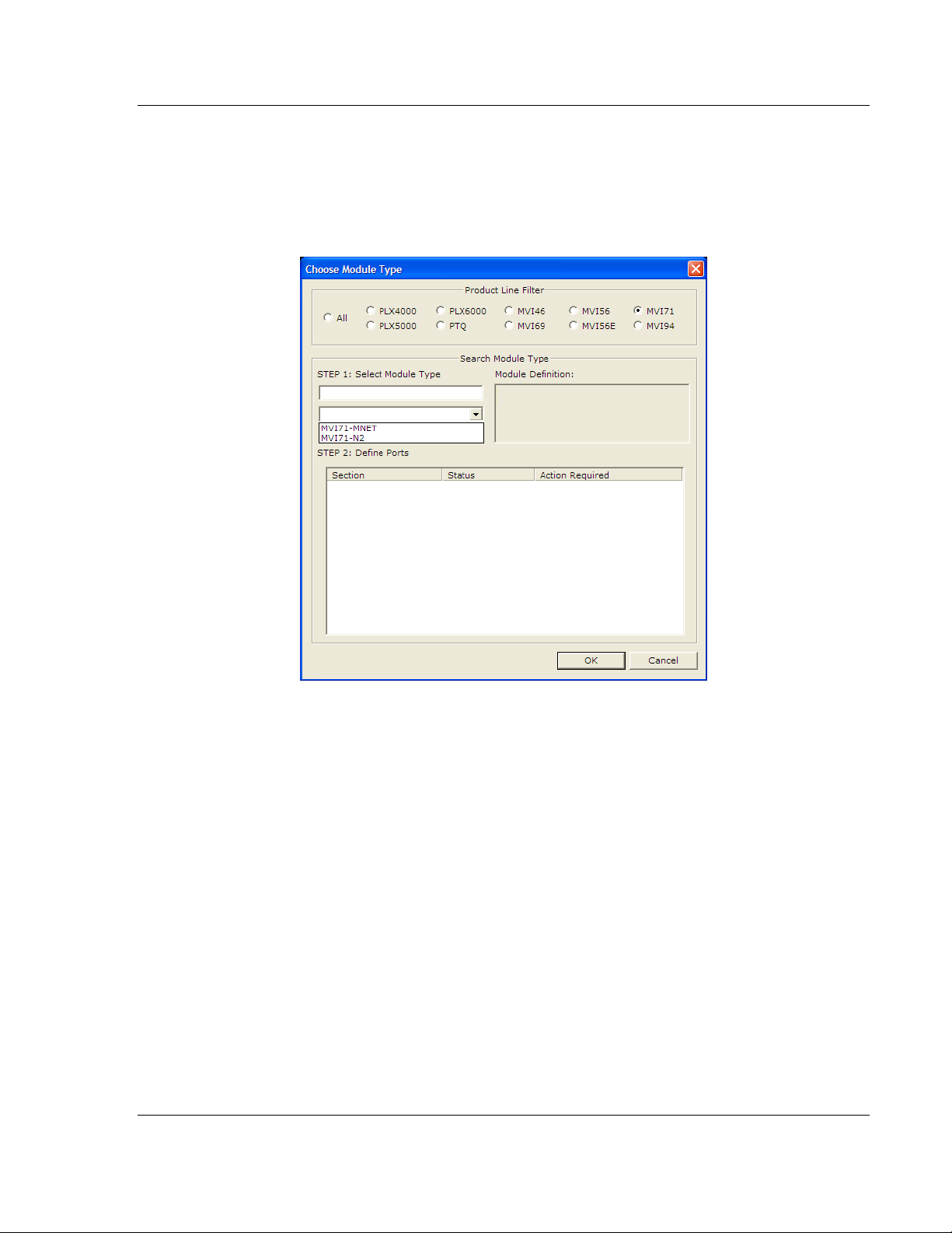
Your first task is to add the MVI71-MNET module to the project.
1 Use the mouse to select "Default Module" in the tree view, and then click the
right mouse button to open a shortcut menu.
2 On the shortcut menu, choose "Choose Module Type". This action opens the
Choose Module Type dialog box.
3 In the Product Line Filter area of the dialog box, select MVI71. In the Select
Module Type dropdown list, select MVI71-MNET, and then click OK to save
your settings and return to the ProSoft Configuration Builder window.
The next task is to set the module parameters.
ProSoft Technology, Inc. Page 25 of 109
June 23, 2009
Page 26
MVI71-MNET ♦ PLC Platform Module Configuration
Modbus TCP/IP Interface Module User Manual
2.7.2 Set Module Parameters
Notice that the contents of the information pane and the configuration pane
changed when you added the MVI71-MNET module to the project.
At this time, you may wish to rename the "Default Project" and "Default Location"
folders in the tree view.
To rename an object:
1 Select the object, and then click the right mouse button to open a shortcut
menu. From the shortcut menu, choose R
ENAME.
2 Type the name to assign to the object.
3 Click away from the object to save the new name.
Module Entries
To configure module parameters
1 Click on the plus sign next to the
2 Double-click the
icon to expand module information.
icon to open the EDIT dialog box.
3 To edit a parameter, select the parameter in the left pane and make your
changes in the right pane.
4 Click OK
to save your changes.
Page 26 of 109 ProSoft Technology, Inc.
June 23, 2009
Page 27

Module Configuration MVI71-MNET ♦ PLC Platform
User Manual Modbus TCP/IP Interface Module
Printing a Configuration File
To print a configuration file:
1 Select the M
ODULE icon, and then click the right mouse button to open a
shortcut menu.
2 On the shortcut menu, choose V
V
IEW CONFIGURATION window.
3 On the V
P
RINT. This action opens the PRINT dialog box.
4 On the P
IEW CONFIGURATION window, open the FILE menu, and choose
RINT dialog box, choose the printer to use from the dropdown list,
select printing options, and then click OK.
IEW CONFIGURATION. This action opens the
2.7.3 [Module]
This section of the configuration describes the database setup and module level
parameters. This section provides the module with a unique name, identifies the
method of failure for the communications for the module if the processor is not in
run, and describes how to initialize the module upon startup.
Module Name
0 to 80 characters
This parameter assigns a name to the module that can be viewed using the
configuration/debug port. Use this parameter to identify the module and the
configuration file.
Error/Status Pointer
-1 to 4955
Starting register location in virtual Modbus database for the error/status table. If a
value of -1 is entered, the error/status data will not be placed in the database. All
other valid values determine the starting location of the data. This data area
includes the module version information and all server error/status data.
Read Register Start
0 to 4999
This parameter specifies the starting register in the module where data will be
transferred from the module to the processor. Valid range for this parameter is 0
to 4999.
Read Register Count
0 to 5000
This parameter specifies the number of registers to be transferred from the
module to the processor. Valid entry for this parameter is 0 to 5000.
ProSoft Technology, Inc. Page 27 of 109
June 23, 2009
Page 28

MVI71-MNET ♦ PLC Platform Module Configuration
Modbus TCP/IP Interface Module User Manual
Write Register Start
0 to 4999
This parameter specifies the starting register in the module where the data will be
transferred from the processor to the module. Valid range for this parameter is 0
to 4999.
Write Register Count
0 to 5000
This parameter specifies the number of registers to transfer from the processor to
the module. Valid entry for this parameter is 0 to 5000 words.
Failure Flag Count
0 through 65535
This parameter specifies the number of successive transfer errors that must
occur before the communication ports are shut down. If the parameter is set to 0,
the communication ports will continue to operate under all conditions. If the value
is set larger than 0 (1 to 65535), communications will cease if the specified
number of failures occur.
Initialize Output Data
Yes or No
The Initialize Output Data parameter determines if the output data for the module
should be initialized with values from the processor. If the value is set to N, the
output data will be initialized to 0. If the value is set to Y during initialization, the
module will invert (for this scan only) all backplane commands (Type 2).
Pass-Through Mode
0, 1, 2 or 3
This parameter specifies the pass-through mode for write messages received by
the MNET and MBAP server ports.
If the parameter is set to 0, all write messages will be placed in the module’s
virtual database.
If a value of 1 is entered, write messages received will be sent to the
processor as unformatted messages.
If a value of 2 is entered, write messages received will be sent to the
processor as formatted messages.
If a value of 3 is entered, write messages received will be sent to the
processor with the bytes swapped in a formatted message.
Page 28 of 109 ProSoft Technology, Inc.
June 23, 2009
Page 29

Module Configuration MVI71-MNET ♦ PLC Platform
User Manual Modbus TCP/IP Interface Module
Duplex/Speed Code
0, 1, 2, 3 or 4
This parameter allows you to force the module to use a specific duplex and
speed setting.
Value = 1: Half duplex, 10 MB speed
Value = 2: Full duplex, 10 MB speed
Value = 3: Half duplex, 100 MB speed
Value = 4: Full duplex, 100 MB speed
Value = 0: Auto negotiate.
Auto Negotiate is the default value for backward compatibility. This feature is not
implemented in older software revisions.
2.7.4 [Static ARP Table]
The Static ARP Table defines a list of static IP addresses that the module will
use when an ARP (Address Resolution Protocol) is required. The module will
accept up to 40 static IP/MAC address data sets.
Use the Static ARP table to reduce the amount of network traffic by specifying IP
addresses and their associated MAC (hardware) addresses that the MVI71MNET module will be communicating with regularly.
Important: If the device in the field is changed, this table must be updated to contain the new MAC
address for the device and downloaded to the module. If the MAC is not changed, no
communications with the module will be provided.
IP Address
Dotted notation
This table contains a list of static IP addresses that the module will use when an
# ARP is required. The module will accept up to 40 static IP/MAC address data
sets.
Important: If the device in the field is changed, this table must be updated to contain the new MAC
address for the device and downloaded to the module. If the MAC is not changed, no
communications with the module will occur.
Hardware MAC Address
Hex Value
This table contains a list of static MAC addresses that the module will use when
an # ARP is required. The module will accept up to 40 static IP/MAC address
data sets.
Important: If the device in the field is changed, this table must be updated to contain the new MAC
address for the device and downloaded to the module. If the MAC is not changed, no
communications with the module will occur.
ProSoft Technology, Inc. Page 29 of 109
June 23, 2009
Page 30

MVI71-MNET ♦ PLC Platform Module Configuration
Modbus TCP/IP Interface Module User Manual
2.7.5 [MNET Client x]
This section defines the configuration for the master device(s) simulated on
MNET port.
Error/Status Pointer
-1 to 4990
Starting register location in virtual database for the error/status table for this
client. If a value of -1 is entered, the error/status data will not be placed in the
database. All other valid values determine the starting location of the data.
Minimum Command Delay
0 to 65535
This parameter specifies the number of milliseconds to wait between the initial
issuance of a command. This parameter can be used to delay all commands sent
to slaves to avoid "flooding" commands on the network. This parameter does not
affect retries of a command as they will be issued when failure is recognized.
Command Error Pointer
-1 to 4999
This parameter sets the address in the internal database where the command
error data will be placed. If the value is set to -1, the data will not be transferred
to the database.
Response Timeout
0 to 65535 milliseconds
This parameter represents the message response timeout period in 1 millisecond
increments. This is the time that a client will wait before re-transmitting a
command if no response is received from the addressed server. The value is set
depending upon the communication network used and the expected response
time of the slowest device on the network.
Retry Count
0 to 10
This parameter specifies the number of times a command will be retried if it fails.
Float Flag
Yes or No
This flag specifies if the floating-point data access functionality is to be
implemented. If the float flag is set to Yes, Modbus functions 3, 6 and 16 will
interpret floating point values for registers as specified by the two following
parameters.
Page 30 of 109 ProSoft Technology, Inc.
June 23, 2009
Page 31

Module Configuration MVI71-MNET ♦ PLC Platform
User Manual Modbus TCP/IP Interface Module
Float Start
0 to 65535
This parameter defines the first register of floating-point data. All requests with
register values greater-than or equal to this value will be considered floating-point
data requests. This parameter is only used if the Float Flag is enabled. For
example, if a value of 7000 is entered, all requests for registers 7000 and above
will be considered as floating-point data.
Float Offset
0 to 9999
This parameter defines the start register for floating-point data in the internal
database. This parameter is used only if the Float Flag is enabled. For example,
if the Float Offset value is set to 3000 and the float start parameter is set to 7000,
data requests for register 7000 will use the internal Modbus register 3000.
ARP Timeout
1 to 60
This parameter specifies the number of seconds to wait for an ARP reply after a
request is issued.
Command Error Delay
0 to 300
This parameter specifies the number of 100 millisecond intervals to turn off a
command in the error list after an error is recognized for the command. If this
parameter is set to 0, there will be no delay.
2.7.6 [MNET Client x Commands]
The [MNET Client x Commands] section of the configuration sets the Modbus
master port command list. This command list polls Modbus slave devices
attached to the Modbus master port. The module supports numerous commands.
This permits the module to interface with a wide variety of Modbus protocol
devices.
The function codes used for each command are those specified in the Modbus
protocol (page
of the record contains the information relating to the MVI71-MNET
communication module and the second part contains information required to
interface to the Modbus slave device.
ProSoft Technology, Inc. Page 31 of 109
June 23, 2009
88). Each command list record has the same format. The first part
Page 32

MVI71-MNET ♦ PLC Platform Module Configuration
Modbus TCP/IP Interface Module User Manual
Command List Overview
In order to interface the MVI71-MNET module with Modbus TCP/IP Server
devices, you must construct a command list. The commands in the list specify
the Server device to be addressed, the function to be performed (read or write),
the data area in the device to interface with and the registers in the internal
database to be associated with the device data. The Client command list
supports up to 100 commands.
The command list is processed from top (command #0) to bottom. A poll interval
parameter is associated with each command to specify a minimum delay time in
tenths of a second between the issuance of a command. If the user specifies a
value of 10 for the parameter, the command will be executed no more frequently
than every 1 second.
Write commands have a special feature, as they can be set to execute only if the
data in the write command changes. If the register data values in the command
have not changed since the command was last issued, the command will not be
executed.
If the data in the command has changed since the command was last issued, the
command will be executed. Use of this feature can lighten the load on the
network. In order to implement this feature; set the enable code for the command
to a value of 2.
Commands Supported by the Module
The format of each command in the list is dependent on the Modbus Function
Code being executed.
The following table lists the functions supported by the module.
Function Code Definition Supported in Client Supported in Server
1 Read Coil Status X X
2 Read Input Status X X
3 Read Holding Registers X X
4 Read Input Registers X X
5 Set Single Coil X X
6 Single Register Write X X
7 Read Exception Status X
8 Diagnostics X
15 Multiple Coil Write X X
16 Multiple Register Write X X
22 Mask Write 4X X
23 Read/Write X
Each command list record has the same general format. The first part of the
record contains the information relating to the communication module and the
second part contains information required to interface to the Modbus TCP/IP
Server device.
Page 32 of 109 ProSoft Technology, Inc.
June 23, 2009
Page 33

Module Configuration MVI71-MNET ♦ PLC Platform
User Manual Modbus TCP/IP Interface Module
Command Entry Formats
The following table shows the structure of the configuration data necessary for
each of the supported commands.
MNET MODBUS Command Structure
Column # 1 2 3 4 5 6 7 8 9 10
Function
Code
fc1 Code Register 1/10th
fc2 Code Register 1/10th
fc3 Code Register 1/10th
fc4 Code Register 1/10th
fc5 Code Register 1/10th
fc6 Code Register 1/10th
fc15 Code Register 1/10th
fc16 Code Register 1/10th
Enable
Code
Internal
Address
Poll
Interval
Time
Seconds
Seconds
Seconds
Seconds
Seconds
Seconds
Seconds
Seconds
Count Swap
Code
Count 0 IP
Count 0 IP
Count Code IP
Count Code IP
Count 0 IP
Count 0 IP
Count 0 IP
Count Code IP
IP
Address
Address
Address
Address
Address
Address
Address
Address
Address
Serv
Slave
Port
Node
Port # Address 1 Register
Port # Address 2 Register
Port # Address 3 Register
Port # Address 4 Register
Port # Address 5 Register
Port # Address 6 Register
Port # Address 15 Register
Port # Address 16 Register
Function
Code
Device
Modbus
Address
The first part of the record is the Module Information, which relates to the ProLinx
module and the second part contains information required to interface to the
Server device.
Command list example:
ProSoft Technology, Inc. Page 33 of 109
June 23, 2009
Page 34

MVI71-MNET ♦ PLC Platform Module Configuration
Modbus TCP/IP Interface Module User Manual
Enable
0, 1, 2
This field defines whether or not the command is to be executed and under what
conditions.
Value Description
0 The command is disabled and will not be executed in the normal polling sequence.
1
2
The command is executed each scan of the command list if the Poll Interval Time is
set to zero. If the Poll Interval time is set, the command will be executed, when the
interval timer expires.
The command will execute only if the internal data associated with the command
changes. This value is valid only for write commands.
Internal Address
0 to 4999
or
0 to 9999
This field specifies the database address in the module's internal database to
associate with the command. The database address is interpreted as bitaddressing or word-addressing, depending on the Modbus function.
For Modbus functions 1, 2, 5, and 15, this parameter is interpreted as bit-
addressing.
For Modbus functions 3, 4, 6, and 16, this parameter is interpreted as word-
addressing.
If the command is a read function, the data received in the response message is
placed at the specified location.
If the command is write function, data used in the command is sourced from the
specified data area.
Poll Interval
0 to 65535
This parameter specifies the minimum interval to execute continuous commands
(Enable code of 1). The parameter is entered in tenths of a second. Therefore, if
a value of 100 is entered for a command, the command executes no more
frequently than every 10 seconds.
Reg Count
Regs: 1 to 125
Coils: 1 to 800
This parameter specifies the number of registers or digital points to be
associated with the command.
Functions 5 and 6 ignore this field as they only apply to a single data point.
For functions 1, 2, and 15, this parameter sets the number of digital points
(inputs or coils) to be associated with the command.
For functions 3, 4, and 16, this parameter sets the number of registers to be
associated with the command.
Page 34 of 109 ProSoft Technology, Inc.
June 23, 2009
Page 35

Module Configuration MVI71-MNET ♦ PLC Platform
User Manual Modbus TCP/IP Interface Module
Swap Code
0, 1, 2, 3
This parameter defines if the data received from the Server is to be ordered
differently than received from the Server device. This parameter is helpful when
dealing with floating-point or other multi-register values, as there is no standard
method of storage of these data types in Server devices. This parameter can be
set to order the register data received in an order useful by other applications.
The following table defines the values and their associated operations:
Swap Code Description
0 None - No Change is made in the byte ordering (1234 = 1234)
1 Words - The words are swapped (1234=3412)
2
3 Bytes - The bytes in each word are swapped (1234=2143)
Words & Bytes - The words are swapped then the bytes in each word are
swapped (1234=4321)
The words should be swapped only when using an even number of words.
Node IP Address
xxx.xxx.xxx.xxx
The IP address of the device being addressed by the command.
Service Port
502 or other supported ports on server
Use a value of 502 when addressing Modbus TCP/IP servers that are compatible
with the Schneider Electric MBAP specifications (this will be most devices). If a
server implementation supports another service port, enter the value here.
Slave Address
1 to 255 (0 is a broadcast)
This parameter specifies the Modbus slave node address on the network to be
considered. Values of 1 to 255 are permitted.
Note: Most Modbus devices only accept an address in the range of 1 to 247, so be careful. If the
value is set to zero, the command will be a broadcast message on the network. The Modbus
protocol permits broadcast commands for write operations. Do not use this node address for read
operations.
ProSoft Technology, Inc. Page 35 of 109
June 23, 2009
Page 36

MVI71-MNET ♦ PLC Platform Module Configuration
Modbus TCP/IP Interface Module User Manual
Modbus Function
1, 2, 3, 4, 5, 6, 15, 16
This parameter specifies the Modbus function to be executed by the command.
These function codes are defined in the Modbus protocol. The following table
defines the purpose of each function supported by the module. More information
on the protocol is available from the Schneider Electric web site
(www.modicon.com).
Modbus Function Code Description
1 Read Coil Status
2 Read Input Status
3 Read Holding Registers
4 Read Input Registers
5 Single Coil Write
6 Single Register Write
15 Multiple Coil Write
16 Multiple Register Write
MB Address in Device
This parameter specifies the starting Modbus register or digital point address to
be considered by the command in the Modbus slave device. Refer to the
documentation of each Modbus slave device on the network for their register and
digital point address assignments.
The FC determines the addresses range and that this value will be the register or
bit OFFSET into a given data range. For instance, if the command is to be a bit
command (FC 1, 2, 5, or 15) to Read/Write a Coil 0X address 00001, then the
value to enter here would be 0. For Coil address 00110, the value here would be
109. For register Read/Write commands (FC 3, 4, 6, or 16) in the 3X (FC4) or 4X
(FC3), say 30001 or 40001, the value here would, again be 0. For 31101 or
41101, the value to enter for this parameter would be 1100.
Comment
0 to 35 alphanumeric characters
Page 36 of 109 ProSoft Technology, Inc.
June 23, 2009
Page 37

Module Configuration MVI71-MNET ♦ PLC Platform
User Manual Modbus TCP/IP Interface Module
2.7.7 [MNET Servers]
This section contains database offset information used by the servers when
accessed by external clients. These offsets can be utilized to segment the
database by data type.
Float Flag
Yes or No
This flag specifies if the floating-point data access functionality is to be
implemented. If the float flag is set to Yes, Modbus functions 3, 6 and 16 will
interpret floating point values for registers as specified by the two following
parameters.
Float Start
0 to 65535
This parameter defines the first register of floating-point data. All requests with
register values greater-than or equal to this value will be considered floating-point
data requests. This parameter is only used if the Float Flag is enabled. For
example, if a value of 7000 is entered, all requests for registers 7000 and above
will be considered as floating-point data.
Float Offset
0 to 9999
This parameter defines the start register for floating-point data in the internal
database. This parameter is used only if the Float Flag is enabled. For example,
if the Float Offset value is set to 3000 and the float start parameter is set to 7000,
data requests for register 7000 will use the internal Modbus register 3000.
ProSoft Technology, Inc. Page 37 of 109
June 23, 2009
Page 38

MVI71-MNET ♦ PLC Platform Module Configuration
Modbus TCP/IP Interface Module User Manual
Output Offset
This parameter defines the start register for the Modbus command data in the
internal database. This parameter is enabled when a value greater than 0 is set.
For example, if the Output Offset value is set to 3000, data requests for Modbus
Coil Register address 00001, will use the internal database register 3000, bit 0. If
the Output Offset value is set to 3000, data requires for Modbus Coil register
address 00016 will use the internal database register 3000, bit 15. Function
codes affected are 1, 5, and 15.
Bit Input Offset
0 to 3999
This parameter defines the start register for Modbus command data in the
internal database. This parameter is enabled when a value greater than 0 is set.
For example, if the Bit Input Offset value is set to 3000, data requests for Modbus
Input Register address 10001 will use the internal database register 3000, bit 0. If
the Bit Input Offset is set to 3000, data requests for Modbus Coil register address
10016 will use the internal database register 3000, bit 15. Function code 2 is
affected.
Holding Register Offset
0 to 4999
This parameter defines the start register for the Modbus Command data in the
internal database. This parameter is enabled when a value greater than 0 is set.
For example, if the Holding Register Offset value is set to 4000, data requests for
Modbus Word register 40001 will use the internal database register 4000.
Function codes affected are 3, 6, 16, & 23.
Word Input Offset
0 to 4999
This parameter defines the start register for Modbus Command data in the
internal database. This parameter is enabled when a value greater than 0 is set.
For example, if the Word Input Offset value is set to 4000, data requests for
Modbus Word register address 30001 will use the internal database register
4000. Function code 4 is affected.
Page 38 of 109 ProSoft Technology, Inc.
June 23, 2009
Page 39

Module Configuration MVI71-MNET ♦ PLC Platform
User Manual Modbus TCP/IP Interface Module
2.7.8 Ethernet Configuration
Use this procedure to configure the Ethernet settings for your module. You must
assign an IP address, subnet mask and gateway address. After you complete
this step, you can connect to the module with an Ethernet cable.
1 Determine the network settings for your module, with the help of your network
administrator if necessary. You will need the following information:
o IP address (fixed IP required) _____ . _____ . _____ . _____
o Subnet mask _____ . _____ . _____ . _____
2 Gateway address _____ . _____ . _____ . _____
3 Double-click the E
dialog box.
THERNET CONFIGURATION icon. This action opens the EDIT
4 Edit the values for my_ip, netmask (subnet mask) and gateway (default
gateway).
5 When you are finished editing, click OK
to save your changes and return to
the ProSoft Configuration Builder window.
ProSoft Technology, Inc. Page 39 of 109
June 23, 2009
Page 40

MVI71-MNET ♦ PLC Platform Module Configuration
Modbus TCP/IP Interface Module User Manual
2.8 Download the Project to the Module
In order for the module to use the settings you configured, you must download
(copy) the updated Project file from your PC to the module.
To Download the Project File
1 In the tree view in ProSoft Configuration Builder, click once to select the
MVI71-MNET module.
2 Open the P
ROJECT menu, and then choose MODULE / DOWNLOAD. The
program will scan your PC for a valid com port (this may take a few seconds).
When PCB has found a valid com port, the D
OWNLOAD dialog box will open.
3 Choose the com port to use from the dropdown list, and then click the
D
OWNLOAD button.
The module will perform a platform check to read and load its new settings.
When the platform check is complete, the status bar in the D
OWNLOAD dialog
box with the message "Module Running".
Page 40 of 109 ProSoft Technology, Inc.
June 23, 2009
Page 41

Ladder Logic MVI71-MNET ♦ PLC Platform User Manual Modbus TCP/IP Interface Module
3 Ladder Logic
Ladder logic is required for application of the MVI71-MNET module. Tasks that
must be handled by the ladder logic are module data transfer, special block
handling, and status data receipt. Additionally, a power-up handler may be
needed to handle the initialization of the module’s data and to clear any
processor fault conditions.
The sample ladder logic, on the ProSoft Solutions CD-ROM, is extensively
commented, to provide information on the purpose and function of each rung. For
most applications, the sample ladder will work without modification.
ProSoft Technology, Inc. Page 41 of 109
June 23, 2009
Page 42

MVI71-MNET ♦ PLC Platform Ladder Logic
Modbus TCP/IP Interface Module User Manual
Page 42 of 109 ProSoft Technology, Inc.
June 23, 2009
Page 43

Diagnostics and Troubleshooting MVI71-MNET ♦ PLC Platform User Manual Modbus TCP/IP Interface Module
4 Diagnostics and Troubleshooting
In This Chapter
Reading Status Data from the Module ..................................................43
LED Status Indicators............................................................................53
The module provides information on diagnostics and troubleshooting in the
following forms:
Status data values are transferred from the module to the processor
Data contained in the module can be viewed through the
Configuration/Debug port attached to a terminal emulator
LED status indicators on the front of the module provide information on the
module’s status
4.1 Reading Status Data from the Module
The MVI71-MNET module returns a 47-word Status Data block that can be used
to determine the module’s operating status. This data is located in the module’s
database at a user set location. This data is transferred to the PLC processor
continuously when the side-connect interface is utilized. For a complete listing of
the status data object, refer to the Reference chapter. The Configuration/Debug
port provides the following functionality:
Full view of the module’s configuration data
View of the module’s status data
Complete display of the module’s internal database (registers 0 to 3999)
Version Information
Control over the module (warm boot, cold boot, transfer configuration)
Facility to upload and download the module’s configuration file
4.1.1 Required Hardware
You can connect directly from your computer’s serial port to the serial port on the
module to view configuration information, perform maintenance, and send
(upload) or receive (download) configuration files.
ProSoft Technology recommends the following minimum hardware to connect
your computer to the module:
80486 based processor (Pentium preferred)
1 megabyte of memory
At least one UART hardware-based serial communications port available.
USB-based virtual UART systems (USB to serial port adapters) often do not
function reliably, especially during binary file transfers, such as when
uploading/downloading configuration files or module firmware upgrades.
A null modem serial cable.
ProSoft Technology, Inc. Page 43 of 109
June 23, 2009
Page 44

MVI71-MNET ♦ PLC Platform Diagnostics and Troubleshooting
Modbus TCP/IP Interface Module User Manual
4.1.2 The Configuration/Debug Menu
The Configuration and Debug menu for this module is arranged as a tree
structure, with the Main Menu at the top of the tree, and one or more sub-menus
for each menu command. The first menu you see when you connect to the
module is the Main menu.
Because this is a text-based menu system, you enter commands by typing the
command letter from your computer keyboard in the diagnostic window in
ProSoft Configuration Builder (PCB). The module does not respond to mouse
movements or clicks. The command executes as soon as you press the
command letter — you do not need to press [E
letter, a new screen will be displayed in your terminal application.
NTER]. When you type a command
Using the Diagnostic Window in ProSoft Configuration Builder
To connect to the module’s Configuration/Debug serial port,
1 Start PCB, and then select the module to test. Click the right mouse button to
open a shortcut menu.
2 On the shortcut menu, choose D
IAGNOSTICS.
Page 44 of 109 ProSoft Technology, Inc.
June 23, 2009
Page 45

Diagnostics and Troubleshooting MVI71-MNET ♦ PLC Platform
User Manual Modbus TCP/IP Interface Module
3 This action opens the D
IAGNOSTICS dialog box. Press [?] to open the Main
Menu.
Important: The illustrations of configuration/debug menus in this section are intended as a general
guide, and may not exactly match the configuration/debug menus in your own module.
If there is no response from the module, follow these steps:
1 Verify that the null modem cable is connected properly between your
computer’s serial port and the module. A regular serial cable will not work.
2 On computers with more than one serial port, verify that your communication
program is connected to the same port that is connected to the module.
If you are still not able to establish a connection, contact ProSoft Technology for
assistance.
Navigation
All of the sub-menus for this module contain commands to redisplay the menu or
return to the previous menu. You can always return from a sub-menu to the next
higher menu by pressing [M] on your keyboard.
The organization of the menu structure is represented in simplified form in the
following illustration:
The remainder of this section shows you the menus available for this module,
and briefly discusses the commands available to you.
ProSoft Technology, Inc. Page 45 of 109
June 23, 2009
Page 46

MVI71-MNET ♦ PLC Platform Diagnostics and Troubleshooting
Modbus TCP/IP Interface Module User Manual
Keystrokes
The keyboard commands on these menus are almost always non-case sensitive.
You can enter most commands in lower case or capital letters.
The menus use a few special characters ([?],
exactly as shown. Some of these characters will require you to use the [S
[-], [+], [@]) that must be entered
HIFT],
[CTRL] or [ALT] keys to enter them correctly. For example, on US English
keyboards, enter the [?]
Also, take care to distinguish capital letter [I]
number [1];
likewise for capital letter [O] and number [0]. Although these
command as [SHIFT][/].
from lower case letter [L] (L) and
characters look nearly the same on the screen, they perform different actions on
the module.
4.1.3 Main Menu
When you first connect to the module from your computer, your terminal screen
will be blank. To activate the main menu, press the [?] key on your computer’s
keyboard. If the module is connected properly, the following menu will appear on
your terminal screen:
Caution: Some of the commands available to you from this menu are designed for advanced
debugging and system testing only, and can cause the module to stop communicating with the
processor or with other devices, resulting in potential data loss or other failures. Only use these
commands if you are specifically directed to do so by ProSoft Technology Technical Support staff.
Some of these command keys are not listed on the menu, but are active nevertheless. Please be
careful when pressing keys so that you do not accidentally execute an unwanted command.
Viewing Block Transfer Statistics
Press [B]
from the Main Menu to view the Block Transfer Statistics screen.
Use this command to display the configuration and statistics of the backplane
data transfer operations between the module and the processor. The information
on this screen can help determine if there are communication problems between
the processor and the module.
Page 46 of 109 ProSoft Technology, Inc.
June 23, 2009
Page 47

Diagnostics and Troubleshooting MVI71-MNET ♦ PLC Platform
User Manual Modbus TCP/IP Interface Module
Tip: To determine the number of blocks transferred each second, mark the numbers displayed at a
specific time. Then some seconds later activate the command again. Subtract the previous
numbers from the current numbers and divide by the quantity of seconds passed between the two
readings.
Viewing Module Configuration
Press [C]
to view the Module Configuration screen.
Use this command to display the current configuration and statistics for the
module.
Opening the Database Menu
Press [D]
to open the Database View menu. Use this menu command to view the
current contents of the module’s database.
Opening the Command List Menu
Press [L]
to open the Command List menu. Use this command to view the
configured command list for the module.
Opening the Command Error List Menu
Press [I]
to open the Command Error List. This list consists of multiple pages of
command list error/status data. Press [?]
to view a list of commands available on
this menu.
Receiving the Configuration File
Press [R]
to download (receive) the current configuration file from the module.
For more information on receiving and sending configuration files, please see
Uploading and Downloading the Configuration File.
Sending the Configuration File
Press [S]
to upload (send) an updated configuration file to the module. For more
information on receiving and sending configuration files, please see Uploading
and Downloading the Configuration File.
Resetting diagnostic data
Press [U]
to reset the status counters for the client and/or servers in the module.
Viewing Version Information
Press [V]
to view Version information for the module.
Use this command to view the current version of the software for the module, as
well as other important values. You may be asked to provide this information
when calling for technical support on the product.
ProSoft Technology, Inc. Page 47 of 109
June 23, 2009
Page 48

MVI71-MNET ♦ PLC Platform Diagnostics and Troubleshooting
Modbus TCP/IP Interface Module User Manual
Values at the bottom of the display are important in determining module
operation. The Program Scan Counter value is incremented each time a
module’s program cycle is complete.
Tip: Repeat this command at one-second intervals to determine the frequency of program
execution.
Warm Booting the Module
Caution: Some of the commands available to you from this menu are designed for advanced
debugging and system testing only, and can cause the module to stop communicating with the
processor or with other devices, resulting in potential data loss or other failures. Only use these
commands if you are specifically directed to do so by ProSoft Technology Technical Support staff.
Some of these command keys are not listed on the menu, but are active nevertheless. Please be
careful when pressing keys so that you do not accidentally execute an unwanted command.
Press [W] from the Main Menu to warm boot (restart) the module. This command
will cause the program to exit and reload, refreshing configuration parameters
that must be set on program initialization. Only use this command if you must
force the module to re-boot.
Viewing Network Status
Press [1]
to view statistics for the network server ports. The Network Server
Ports Status screen shows the number of requests, responses, and errors for
each network server.
Viewing Client Status
Press [0]
Viewing Client Configuration
Press [5]
Viewing Server Configuration
Press [6]
(zero) to display the statistics of the client.
to display the configuration information for the client.
to view configuration information for the MNET Servers.
Page 48 of 109 ProSoft Technology, Inc.
June 23, 2009
Page 49

Diagnostics and Troubleshooting MVI71-MNET ♦ PLC Platform
User Manual Modbus TCP/IP Interface Module
Exiting the Program
Caution: Some of the commands available to you from this menu are designed for advanced
debugging and system testing only, and can cause the module to stop communicating with the
processor or with other devices, resulting in potential data loss or other failures. Only use these
commands if you are specifically directed to do so by ProSoft Technology Technical Support staff.
Some of these command keys are not listed on the menu, but are active nevertheless. Please be
careful when pressing keys so that you do not accidentally execute an unwanted command.
Press [ESC] to restart the module and force all drivers to be loaded. The module
will use the configuration stored in the module's Flash memory to configure the
module.
4.1.4 Modbus Database View
Press [D] to open the Modbus Database View menu. Use this command to view
the module’s internal database values. Press [?]
this menu.
to view a list of commands on
All data contained in the module’s database is available for viewing using the
commands. Refer to Modbus Protocol Specification (page
88) for information on
the structure of Modbus messages. Each option available on the menu is
discussed in the following topics.
Viewing Register Pages
To view sets of register pages, use the keys described below:
Command Description
[0]
[1]
[2]
Display registers 0 to 99
Display registers 1000 to 1099
Display registers 2000 to 2099
And so on. The total number of register pages available to view depends on your
module’s configuration.
Redisplaying the Current Page
Press [S]
to display the current page of data.
ProSoft Technology, Inc. Page 49 of 109
June 23, 2009
Page 50

MVI71-MNET ♦ PLC Platform Diagnostics and Troubleshooting
Modbus TCP/IP Interface Module User Manual
Moving Back Through 5 Pages of Registers
Press [-]
from the Database View menu to skip five pages back in the database
to see the previous 100 registers of data.
Viewing the Previous 100 Registers of Data
Press [P]
from the Database View menu to display the previous 100 registers of
data.
Moving Forward Through 5 Pages of Registers
Press [+]
from the Database View menu to skip five pages ahead in the database
to see the next 100 registers of data.
Viewing the Next 100 Registers of Data
Press [N]
from the Database View menu to select and display the next 100
registers of data.
Viewing Data in Decimal Format
Press [D]
to display the data on the current page in decimal format.
Viewing Data in Hexadecimal Format
Press [H]
to display the data on the current page in hexadecimal format.
Viewing Data in Floating Point Format
Press [F]
from the Database View menu. Use this command to display the data
on the current page in floating point format. The program assumes that the
values are aligned on even register boundaries. If floating-point values are not
aligned as such, they are not displayed properly.
Viewing Data in ASCII (Text) Format
Press [A]
to display the data on the current page in ASCII format. This is useful
for regions of the database that contain ASCII data.
Returning to the Main Menu
Press [M]
to return to the Main Menu.
Page 50 of 109 ProSoft Technology, Inc.
June 23, 2009
Page 51

Diagnostics and Troubleshooting MVI71-MNET ♦ PLC Platform
User Manual Modbus TCP/IP Interface Module
4.1.5 Command List Menu
Use this menu to view the configured command list for the module. Press [?] to
view a list of commands available on this menu.
M = Main Menu
Protocol Menu
Command List Menu
Redisplaying the Menu
Press [?]
to display the current menu. Use this command when you are looking
? = Display Menu
S = Show Again
P = Previous Page
N = Next Page
M = Main Menu
Redisplays (refreshes) this menu
Redisplays last selected page of data
Goes back one page of data
Goes forward one page of data
Goes up one level to main menu
at a screen of data, and want to view the menu choices available to you.
Redisplaying the Current Page
Press [S] to redisplay the current page of data.
Use this command to display the current page of commands. Ten commands are
displayed on each page.
If an enabled command has an error, the EN field will contain a value of -1. This
indicates that the command will be re-issued every 30 seconds.
Viewing the Previous Page of Commands
Press [P]
Viewing the Next Page of Commands
Press [N]
Returning to the Main Menu
Press [M]
to display the previous page of commands.
to display the next page of commands.
to return to the Main Menu.
ProSoft Technology, Inc. Page 51 of 109
June 23, 2009
Page 52

MVI71-MNET ♦ PLC Platform Diagnostics and Troubleshooting
Modbus TCP/IP Interface Module User Manual
4.1.6 Network Menu
The network menu allows you to send, receive, and view the WATTCP.CFG file
that contains the IP and gateway addresses, and other network information.
M = Main Menu
@ = Network Menu
? = Display Menu
R = Receive WATTCP.CFG
S = Send WATTCP.CFG
V = View WATTCP.CFG View WATTCP.CFG file on module
M = Main Menu
Redisplays (refreshes) this menu
Upload WATTCP.CFG to m o dule
Download WATTCP.CFG to PC
Return to M a in Menu
Transferring WATTCP.CFG to the module
Press [R]
to transfer a new WATTCP.CFG file from the PC to the module. Use
this command to change the network configuration for the module (for example,
the module’s IP address).
Press [Y] to confirm the file transfer, and then follow the instructions on the
terminal screen to complete the file transfer process.
Transferring WATTCP.CFG to the PC
Press [S]
Press [Y]
to transfer the WATTCP.CFG file from the module to your PC.
to confirm the file transfer, and then follow the instructions on the
terminal screen to complete the file transfer process.
After the file has been successfully transferred, you can open and edit the file to
change the module’s network configuration.
Viewing the WATTCP.CFG file on the module
Press [V]
to view the module’s WATTCP.CFG file. Use this command to confirm
the module’s current network settings.
Returning to the Main Menu
Press [M]
to return to the Main Menu.
Page 52 of 109 ProSoft Technology, Inc.
June 23, 2009
Page 53

Diagnostics and Troubleshooting MVI71-MNET ♦ PLC Platform
User Manual Modbus TCP/IP Interface Module
4.2 LED Status Indicators
The LEDs indicate the module’s operating status as follows:
ProSoft
Module
CFG Green
BP ACT Amber
OK Red/
Color Status Indication
On
Off No data is being transferred on the Configuration/Debug port.
On Port not used P1 Green
Off Port not used
On Port not used P2 Green
Off Port not used
Off The MVI71-MNET is working normally. APP Amber
On
On
Off
Off
Green
Green The module is operating normally.
Red
Off The battery voltage is OK and functioning. BAT Red
On
Data is being transferred between the module and a remote
terminal using the Configuration/Debug port.
The MVI71-MNET module program has recognized a
communication error on one of its Modbus ports.
The LED is on when the module is performing a write
operation on the backplane.
The LED is off when the module is performing a read
operation on the backplane. Under normal operation, the LED
should blink rapidly on and off.
The card is not receiving any power and is not securely
plugged into the rack.
The program has detected an error or is being configured. If
the LED remains red for over 10 seconds, the program has
probably halted. Remove the card from the rack and re-insert
the card to restart the module’s program.
The battery voltage is low or battery is not present. Allow
battery to charge by keeping module plugged into rack for 24
hours. If BAT LED still does not go off, contact ProSoft
Technology, as this is not a user serviceable item.
If a configuration error is found for the client, the client configuration error word
will have a value other than zero. The configuration error word bits have the
following definitions:
Bit Description Value
0 0x0001
1 0x0002
2 0x0004
3 0x0008
4 Invalid retry count parameter 0x0010
5 The float flag parameter is not valid. 0x0020
6 The float start parameter is not valid. 0x0040
7 The float offset parameter is not valid. 0x0080
8 0x0100
9 0x0200
ProSoft Technology, Inc. Page 53 of 109
June 23, 2009
Page 54

MVI71-MNET ♦ PLC Platform Diagnostics and Troubleshooting
Modbus TCP/IP Interface Module User Manual
Bit Description Value
10 0x0400
11 0x0800
12 0x1000
13 0x2000
14 0x4000
15 0x8000
Correct any invalid data in the configuration for proper module operation. When
the configuration contains a valid parameter set, all the bits in the configuration
word will be clear. This does not indicate that the configuration is valid for the
user application. Make sure each parameter is set correctly for the specific
application.
If the APP, BP ACT and OK LEDs blink at a rate of every one-second, this
indicates a serious problem with the module. Call ProSoft Technology support to
arrange for repairs.
4.2.1 Ethernet LED Indicators
LED State Description
Off No activity on the Ethernet port. Data
Green Flash The Ethernet port is actively transmitting or receiving data.
Link
Off
Green Solid
No physical network connection is detected. No Ethernet
communication is possible. Check wiring and cables.
Physical network connection detected. This LED must be on
solid for Ethernet communication to be possible.
4.2.2 Clearing a Fault Condition
Typically, if the OK LED on the front of the module turns red for more than ten
seconds, a hardware problem has been detected in the module, or the program
has exited.
To clear the condition, follow these steps:
1 Turn off power to the rack
2 Remove the card from the rack
3 Verify that all jumpers are set correctly
4 If the module requires a Compact Flash card, verify that the card is installed
correctly
5 Re-insert the card in the rack and turn the power back on
6 Verify the configuration data being transferred to the module from the PLC
processor.
If the module's OK LED does not turn green, verify that the module is inserted
completely into the rack. If this does not cure the problem, contact ProSoft
Technology Support.
Page 54 of 109 ProSoft Technology, Inc.
June 23, 2009
Page 55

Diagnostics and Troubleshooting MVI71-MNET ♦ PLC Platform
User Manual Modbus TCP/IP Interface Module
4.2.3 Troubleshooting
Use the following troubleshooting steps if you encounter problems when the
module is powered up. If these steps do not resolve your problem, please contact
ProSoft Technology Technical Support.
Processor Errors
Problem Description Steps to take
Processor Fault
Processor I/O LED
flashes
Module Errors
Problem Description Steps to take
BP ACT LED remains
off or blinks slowly
MVI56E modules with
scrolling LED display:
<Backplane Status>
condition reads ERR
OK LED remains red
Verify that the module is plugged into the slot that has been configured
for the module.
Verify that the slot location in the rack has been configured correctly in
the ladder logic.
This indicates a problem with backplane communications. Verify that all
modules in the rack are configured in the ladder logic.
This indicates that backplane transfer operations are failing. Connect to
the module’s Configuration/Debug port to check this.
To establish backplane communications, verify the following items:
The processor is in Run mode.
The backplane driver is loaded in the module.
The module is configured for read and write block data transfer.
The ladder logic handles all read and write block situations.
The module is configured in the processor.
The program has halted or a critical error has occurred. Connect to the
Configuration/Debug port to see if the module is running. If the program
has halted, turn off power to the rack, remove the card from the rack and
re-insert the card in the rack, and then restore power to the rack.
ProSoft Technology, Inc. Page 55 of 109
June 23, 2009
Page 56

MVI71-MNET ♦ PLC Platform Diagnostics and Troubleshooting
Modbus TCP/IP Interface Module User Manual
Page 56 of 109 ProSoft Technology, Inc.
June 23, 2009
Page 57

Reference MVI71-MNET ♦ PLC Platform
User Manual Modbus TCP/IP Interface Module
5 Reference
In This Chapter
Product Specifications...........................................................................57
Functional Overview..............................................................................59
Cable Connections................................................................................78
MVI71-MNET Status Data Definition for Side Connect File...................82
Status Data Structure for Database Storage.........................................83
Client Error/Status Data.........................................................................85
Modbus Protocol Specification..............................................................88
5.1 Product Specifications
The MVI71 Modbus TCP/IP Client/Server Communication Module allows
Rockwell Automation PLC processors to interface easily with other Modbus
compatible devices.
Compatible devices include Modicon PAC’s as well as a wide variety of
instruments and devices. A 5000-word register space in the module exchanges
data between the processor and the Modbus network.
5.1.1 General Specifications
Single Slot - 1771 backplane compatible
The module is recognized as an Input/Output module and has access to
processor memory for data transfer between processor and module
Ladder Logic is used for data transfer between module and processor.
Sample ladder file included.
10/100 MB Ethernet port
Module I/O data memory mapping supports up to 5000 registers and is user
definable
ProSoft Configuration Builder (PCB) software supported, a Windows-based
graphical user interface providing simple product and network configuration
Sample Ladder Logic for data transfer between module and processor and
module configuration
Personality Module (non-volatile CF card) used to store module and network
configuration allowing for in the field quick product replacement.
ProSoft Technology, Inc. Page 57 of 109
June 23, 2009
Page 58

MVI71-MNET ♦ PLC Platform Reference
Modbus TCP/IP Interface Module User Manual
5.1.2 Hardware Specifications
Specification Description
Form Factor
Backplane current load 800 mA @ 5 V
Operating temperature 0 to 60°C (32 to 140°F)
Storage temperature -40 to 85°C (-40 to 185°F)
Shock 30g operational
Vibration 5 g from 10150 Hz
Relative humidity 5% to 95% (non-condensing)
LED Indicators Module status
Configuration Serial port (CFG) DB-9M PC compatible
Ethernet Port (Ethernet modules) RJ45 Connector
Single Slot 1771 chassis compatible
BTR/BTW data transfer
Local or remote rack
50g non-operational
Backplane transfer status
Application status
Serial activity and error LED status
RS-232
Hardware handshaking
Link and activity LED indicators
Electrical Isolation 1500 V rms at 50 Hz to 60 Hz for 60 s,
applied as specified in section 5.3.2 of IEC 60950: 1991
Ethernet Broadcast Storm Resiliency = less than or equal to
5000 [ARP] frames-per-second and less than or equal to 5
minutes duration
5.1.3 Functional Specifications
10/100 MB Ethernet Application port
Supports Enron version of Modbus protocol for floating point data
transactions
PCB includes a powerful Modbus network analyzer
Special functions (command control, event commands, status, etc.) are
supported by message transfer (unscheduled) using the MSG instruction
Configurable parameters for the client including a minimum response delay of
0 to 65535 ms and floating point support
Supports five independent server connections for Service Port 502
Supports five independent server connections for Service Port 2000
All data mapping begins at Modbus register 40001.
Error codes, network error counters, and port status data available in user
data memory
Page 58 of 109 ProSoft Technology, Inc.
June 23, 2009
Page 59

Reference MVI71-MNET ♦ PLC Platform
User Manual Modbus TCP/IP Interface Module
Server Specifications
The MVI71-MNET module accepts Modbus function code commands of 1, 2, 3,
4, 5, 6, 8, 15, 16, 17, 22 and 23 from an attached Modbus Client unit. A port
configured as a Modbus server permits a remote Client to interact with all data
contained in the module. This data can be derived from other Modbus server
devices on the network, through a Client port, or from the ControlLogix
processor.
Client Specifications
A port configured as a virtual Modbus master device on the MVI71-MNET
module actively issues Modbus commands to other nodes on the Modbus
network. One hundred (100) commands are supported on each port. Additionally,
the master ports have an optimized polling characteristic that polls slaves with
communication problems less frequently. The PLC processor can be
programmed to control the activity on the port by actively selecting commands
from the command list to execute or issuing commands directly from the ladder
logic.
5.2 Functional Overview
This section describes how the MVI71-MNET module transfers data between
itself and the processor, and how it implements the Modbus TCP/IP protocol.
5.2.1 General Concepts
The following discussion explains several concepts that are important for
understanding the operation of the MVI71-MNET module.
Module Power Up
On power up the module begins performing the following logical functions:
1 Initialize hardware components
o Initialize PLC backplane driver
o Test and Clear all RAM
o Initialize the serial communication ports
2 Initialize the TCP/IP Stack and Ethernet interface module
3 Read configuration for module from MNET.CFG file on Compact Flash Disk
4 Initialize Module Register space
5 Enable Server Drivers
6 Enable Client Driver
After the module has received the configuration, the module will begin
communicating with other nodes on the network, depending on the configuration.
ProSoft Technology, Inc. Page 59 of 109
June 23, 2009
Page 60

MVI71-MNET ♦ PLC Platform Reference
Modbus TCP/IP Interface Module User Manual
Main Logic Loop
Upon completing the power up configuration process, the module enters an
infinite loop that performs the functions shown in the following diagram.
From Power Up Logic
Call I/O Handler
Call CFG/DEBUG Port
Driver
Call Ne twork Clie nt &
Server Drivers
Transfers data between the module and processor
Rx and Tx buffer routines are interrupt driven. Call to
serial port routines check to see if there is any data
in the buffer, and depending on the value, will either
service the buffe r or wait fo r more characte rs.
Call N etwork Client & Server Drivers
Call I/O Han dler
(user, status, etc.)
Call Serial P ort Driver
Generate messages and
respond to messages received.
Block Transfer Backplane Data Transfer
The MVI71-MNET module communicates directly over the PLC backplane for the
block transfer interface. Data is paged between the module and the PLC
processor across the backplane using BTR and BTW operations. Data is
transferred from the module to the processor using the BTR blocks, and data is
transferred from the processor to the module using the BTW blocks.
Page 60 of 109 ProSoft Technology, Inc.
June 23, 2009
Page 61

Reference MVI71-MNET ♦ PLC Platform
User Manual Modbus TCP/IP Interface Module
The following illustration shows the data transfer method used to move data
between the PLC processor, the MVI71-MNET module and the Modbus TCP/IP
Network.
All data transferred between the module and the processor over the backplane is
through the BTR and BTW blocks. Ladder logic must be written in the PLC
processor to interface the block data with user data files. All data used by the
module is stored in its internal database. The following illustration shows the
layout of the database:
Module’s Internal Database Structure
5000 registers for user data
Data contained in this database is paged through the block transfer interface by
coordination of the PLC ladder logic and the MVI71-MNET module's program. Up
to 64 words of data can be transferred from the module to the processor at a
time. Up to 64 words of data can be transferred from the processor to the
module. The read and write block identification codes in each data block
determine the function to be performed or the content of the data block.
Register Data
0
4999
ProSoft Technology, Inc. Page 61 of 109
June 23, 2009
Page 62

MVI71-MNET ♦ PLC Platform Reference
Modbus TCP/IP Interface Module User Manual
The module uses the following block numbers:
Block Range Descriptions
-1 Null block
0 Null block
1 to 84 Read or write data
1000 to 1083 Output Initialization Blocks
2000 Event Command Block
5001 to 5006 Command Control
9956 F ormatted pass-through block from function 6 or 16 with word data.
9957 F ormatted pass-through block from function 6 or 16 with floating-point data.
9958 F ormatted pass-through block from function 5.
9959 F ormatted pass-through block from function 15.
9960 F ormatted pass-through block from function 22.
9961 F ormatted pass-through block from function 23.
9970 F unction 99 indication block.
9996 Unformatted Pass-through block with raw Modbus message.
9998 W arm-boot control block
9999 Cold-boot control block
These block identification codes can be broken down into a few groups: Normal
data transfer blocks (-1 to 84), Initialization blocks (1000 to 1083), Command
control blocks (2000, 5000 to 5006, 9998 and 9999) and pass-through function
blocks (9956 to 9961, 9970 and 9996). Each of these groups of blocks are
discussed in the following topics:
Normal Data Transfer
Normal data transfer includes the paging of the user data found in the module’s
internal database in registers 0 to 4999 and the status data. These data are
transferred through read (BTR) and write (BTW) blocks. The following topics
describe the function and structure of each block.
Read Block
These blocks of data transfer information from the module to the PLC processor.
The following table describes the structure of the input image.
Offset Description Length
0 Read Block ID 1
1 Write Block ID 1
2 to 61 Read Data 60
62 to 63 Spare 2
The Read Block ID is an index value used to determine the location of where the
data will be placed in the PLC processor controller tag array of module read data.
Each transfer can move up to 60 words (block offsets 2 to 61) of data.
Page 62 of 109 ProSoft Technology, Inc.
June 23, 2009
Page 63

Reference MVI71-MNET ♦ PLC Platform
User Manual Modbus TCP/IP Interface Module
The Write Block ID associated with the block requests data from the PLC
processor. Under normal program operation, the module sequentially sends read
blocks and requests write blocks. For example, if the application uses three read
and two write blocks, the sequence will be as follows:
R1W1→R2W2→R3W1→R1W2→R2W1→R3W2→R1W1→
This sequence will continue until interrupted by other write block numbers sent by
the controller or by a command request from a node on the Modbus network or
operator control through the module’s Configuration/Debug port.
Write Block
These blocks of data transfer information from the PLC processor to the module.
The following table describes the structure of the output image.
Offset Description Length
0 Write Block ID 1
1 to 60 Write Data 60
61 to 63 Spare 3
The Write Block ID is an index value used to determine the location in the
module’s database where the data will be placed. Each transfer can move up to
60 words (block offsets 1 to 60) of data.
Initialize Output Data
When the module performs a restart operation, it will request blocks of output
data from the processor to initialize the module’s output data. Use the Initialize
Output Data parameter in the configuration file to bring the module to a known
state after a restart operation. The following table describes the structure of the
request block.
Offset Description Length
0 1000 to 1083 1
1 1000 to 1083 1
2 to 63 Spare 62
The block number in word 0 of the block determines the data set of up to 60
output words to transfer from the processor. Ladder logic in the processor must
recognize these blocks and place the correct information in the output image to
be returned to the module. The format of the returned write block is shown in the
following table.
Offset Description Length
0 1000 to 1083 1
1 to 60 Output Data 60
61 to 63 Spare 3
ProSoft Technology, Inc. Page 63 of 109
June 23, 2009
Page 64

MVI71-MNET ♦ PLC Platform Reference
Modbus TCP/IP Interface Module User Manual
Command Control Blocks
Command control blocks are special blocks used to control the module. The
current version of the software supports four command control blocks: event
command control, command control, warm boot and cold boot.
Event Command
Event command control blocks send Modbus TCP/IP commands directly from the
ladder logic to one of the client on the module. The following table describes the
format of these blocks.
Offset Description Length
0 2000 1
1 to 4 IP Address 4
5 Service Port 1
6 Slave Address 1
7 Internal DB Address 1
8 Point Count 1
9 Swap Code 1
10 Modbus Function Code 1
11 Device Database Address 1
12 to 63 Spare 52
The parameters passed with the block construct the command. The IP Address
for the node to reach on the network is entered in four registers (1 to 4). Each
digit of the IP address is entered in the appropriate register.
For example, to interface with node 192.168.0.100, enter the values 192, 168, 0
and 100 in registers 1 to 4. The Service Port field selects the TCP service port
on the server to connect. If the parameter is set to 502, a standard MBAP
message will be generated. All other service port values will generate a Modbus
command message encapsulated in a TCP/IP packet.
The Internal DB Address parameter specifies the module’s database location to
associate with the command. The Point Count parameter defines the number of
points or registers for the command. The Swap Code is used with Modbus
functions 3 and 4 requests to change the word or byte order. The Modbus
Function Code has one of the following values 1, 2, 3, 4, 5, 6, 15 or 16. The
Device Database Address is the Modbus register or point in the remote slave
device to be associated with the command.
When the module receives the block, it will process it and place it in the
command queue. The following table describes the format of this block.
Word Description
0
1 to 4
This word contains the block 2000 identification code to indicate that this block contains a
command to execute by the Client Driver.
These words contain the IP address for the server the message is intended. Each digit (0
to 255) of the IP address is placed in one of the four registers. For example, to reach IP
address 192.168.0.100, enter the following values in words 1 to 4 → 192, 168, 0 and 100.
The module will construct the normal dotted IP address from the values entered. The
values entered will be anded with the mask 0x00ff to insure the values are in the range of
0 to 255.
Page 64 of 109 ProSoft Technology, Inc.
June 23, 2009
Page 65

Reference MVI71-MNET ♦ PLC Platform
User Manual Modbus TCP/IP Interface Module
Word Description
5
6
7
8
9
10 This word contains the Modbus function code to be used with the command.
11
12 to 63 Spare
This word contains the TCP service port the message will be interfaced. For example, to
interface with a MBAP device, the word should contain a value of 502. To interface with a
MNET device, a value of 2000 should be utilized. Any value from 0 to 65535 is permitted.
A value of 502 will cause a MBAP formatted message to be generated. All other values
will generate an encapsulated Modbus message.
This word contains the Modbus node address to use with the message. This field should
have a value from 0 to 247.
This word contains the internal Modbus address in the module to be used with the
command. This word can contain a value from 0 to 4999.
This word contains the count parameter that determines the number of digital points or
registers to associate with the command.
The parameter specifies the swap type for the data. This function is only valid for function
codes 3 and 4.
This word contains the Modbus address in the slave device to be associated with the
command.
The module will respond to each command block with a read block. The following
table describes the format of this block.
Word Description
0 This word contains the block identification code 2000 requested by the processor.
1 This word contains the next read request block identification code.
2
3 to 63 Spare
This word contains the result of the event request. If a value of one is present, the
command was issued. If a value of zero is present, no room was found in the command
queue.
Word two of the block can be used by the ladder logic to determine if the
command was added to the command queue of the module. The command will
only fail if the command queue for the port is full (100 commands for each
queue).
Command Control
Command control blocks place commands in the command list into the
command queue. The client has a command queue of up to 100 commands. The
module services commands in the queue before the user defined command list.
This gives high priority to commands in the queue. Commands placed in the
queue through this mechanism must be defined in the module's command list.
Under normal command list execution, the module will only execute commands
with the Enable parameter set to one or two. If the value is set to zero, the
command is skipped. Commands may be placed in the command queue with an
Enable parameter set to zero using this feature. These commands can then be
executed using the command control blocks.
One to six commands can be placed in the command queue with a single
request. The following table describes the format for this block.
Word Description
0 Command queue block identification code of 5001 to 5006.
1
This word contains the index in the command list for the first command to be entered
into the command queue.
ProSoft Technology, Inc. Page 65 of 109
June 23, 2009
Page 66

MVI71-MNET ♦ PLC Platform Reference
Modbus TCP/IP Interface Module User Manual
Word Description
2
3
4
5
6
7 to 63 Spare
This word contains the index in the command list for the second command to be entered
into the command queue.
This word contains the index in the command list for the third command to be entered
into the command queue.
This word contains the index in the command list for the fourth command to be entered
into the command queue.
This word contains the index in the command list for the fifth command to be entered
into the command queue.
This word contains the index in the command list for the sixth command to be entered
into the command queue.
The last digit in the block code defines the number of commands to process in
the block. For example, a block code of 5003 contains 3 command indexes that
are to be placed in the command queue. The Command index parameters in the
block have a range of 0 to 99 and correspond to the module's command list
entries.
The module responds to a command control block with a block containing the
number of commands added to the command queue for the port. The following
table describes the format for this block.
Word Description
0 This word contains the block 5001 to 5006 requested by the processor.
1 This word contains the next write block identification code.
2
3 to 63 Spare
This word contains the number of commands in the block placed in the command
queue.
Warm Boot
This block is sent from the PLC processor to the module (output image) when the
module is required to perform a warm-boot (software reset) operation. This block
is commonly sent to the module any time configuration data modifications are
made in the controller tags data area. This will force the module to read the new
configuration information and to restart. The following table describes the format
of the control block.
Offset Description Length
0 9998 1
1 to 63 Spare 63
Cold Boot
This block is sent from the PLC processor to the module (output image) when the
module is required to perform the cold boot (hardware reset) operation. This
block is sent to the module when a hardware problem is detected by the ladder
logic that requires a hardware reset. The following table describes the format of
the control block.
Offset Description Length
0 9999 1
1 to 63 Spare 63
Page 66 of 109 ProSoft Technology, Inc.
June 23, 2009
Page 67

Reference MVI71-MNET ♦ PLC Platform
User Manual Modbus TCP/IP Interface Module
Pass-Through Control Blocks
If the module is set for pass-through operation by placing a value of 1 to 3 in the
configuration file parameter Pass-Through Mode, the module will send special
blocks to the module when a write request is received from a client. Any Modbus
function 5, 6, 15 or 16 commands will be passed from the server to the processor
using this block identification numbers 9956 to 9961, 9970 and 9996. Ladder
logic must handle the receipt of these blocks and to place the enclosed data into
the proper controller tags in the module.
There are two basic modes of operation when the pass-through feature is
utilized: Unformatted (code 1) and Formatted (code 2 or 3). The unformatted
mode will pass the message received on the server directly to the processor
without any processing. The following table describes the format of the read
block.
Offset Description Length
0 9996 1
1 9996 1
2 Number of bytes in Modbus msg 1
3 Reserved (always 0) 1
4 to 63 Modbus message received 60
The ladder logic should copy and parse the received message and control the
processor as expected by the master device. The processor must respond to the
pass-through control block with a write block with the following format.
Offset Description Length
0 9996 1
1 to 63 Spare 63
This will inform the module that the command has been processed and can be
cleared from the pass-through queue.
In formatted pass-through mode, the module will process the received write
request and generate a special block dependent on the function received. There
are two modes of operation when the formatted pass-through mode is selected. If
code 2 is utilized (no swap), the data received in the message is presented in the
order expected by the processor. If code 3 is utilized (swap mode), the bytes in
the data area of the message will be swapped. This selection is applied to all
received write requests. The block identification code used with the request is
dependent on the Modbus function requested. Block 9956 passes word type data
for functions 6 and 16. Block 9957 passes a floating-point message for functions
6 and 16. Block 9958 is utilized when Modbus function 5 data is received. Block
9959 is employed when function 15 is recognized. Block 9960 is used for
function 22 and Block 9961 is used for function 23 requests. Block 9970 is
utilized for function 99.
The following tables describe the format for the read blocks.
Offset Description Length
0 9956, 9957, 9958, 9960 or 9961 1
1 9956, 9957, 9958, 9960 or 9961 1
2 Number of word registers in Modbus data set 1
ProSoft Technology, Inc. Page 67 of 109
June 23, 2009
Page 68

MVI71-MNET ♦ PLC Platform Reference
Modbus TCP/IP Interface Module User Manual
Offset Description Length
3 Starting address for Modbus data set 1
4 to 63 Modbus data set 60
Offset Description Length
0 9959 1
1 9959 1
2 Number of word registers in Modbus data set 1
3 Starting word address for Modbus data set 1
4 to 33 Modbus data set 30
34 to 63
Offset Description Length
0 9970 1
1 9970 1
2 1 1
3 0 1
4 to 63 Spare data area 60
Bit mask to use with the data set. Each bit to be considered
with the data set will have a value of 1 in the mask. Bits to
ignore in the data set will have a value of 0 in the mask.
30
The ladder logic should copy and parse the received message and control the
processor as expected by the master device. The processor must respond to the
formatted pass-through control blocks with a write block. The following tables
describe the format of the write blocks.
Offset Description Length
0 9956, 9957, 9958, 9960 or 9961 1
1 to 63 Spare 63
Offset Description Length
0 9959 1
1 to 63 Spare 63
Offset Description Length
0 9970 1
1 to 63 Spare 63
In order to copy status data from module to processor, use the Error/Status
Pointer parameter in the [Module] section of the configuration file.
Move Status to desired database registers, then create a rung in the ladder logic
to pass them to the processor.
Program Scan Counter 1
Block Transfer Status 6
Not used 10
MNet Server Status 10
MBAP Server Status 10
Page 68 of 109 ProSoft Technology, Inc.
June 23, 2009
Page 69

Reference MVI71-MNET ♦ PLC Platform
User Manual Modbus TCP/IP Interface Module
Side-Connect Backplane Data Transfer
The side-connect interface is the simplest method to implement the module. No
ladder logic is required for the interface because the driver handles data
movement between the module and the processor automatically. The data flow
diagram associated with this interface is shown in the following diagrams:
The configuration information for the module determines the size of the read and
write data areas and the locations of these data sets in the module’s internal
database. Therefore, to use this interface, just set up the files required by the
module. The following table lists the files required for the side-connect interface:
File Number Example Size Description
Cfg File N10 200 Control/Status File
Cfg File+1 N11 to 1000 Data transferred from the module to the processor
Other files for read data
Cfg File+1+n N12 to 1000 Data transferred from the processor to the module
Cfg File+1+n+m Other files for write data
n is the number of read data files minus one. Each file contains up to 1000
words.
m is the number of write data files minus one. Each file contains up to 1000
words.
The number of read and write files are dependent on the modules configuration.
Two examples follow:
ProSoft Technology, Inc. Page 69 of 109
June 23, 2009
Page 70

MVI71-MNET ♦ PLC Platform Reference
Modbus TCP/IP Interface Module User Manual
Example of 240 words of read and write data (cfg file=10)
Data Files Description
N11:0 to 239 Read data
N12:0 to 239 Write data
Example of 2300 read and 3500 write data registers (cfg file=10)
Data Files Description
N11:0 to 999 Read data words 0 to 999
N12:0 to 999 Read data words 1000 to 1999
N13:0 to 299 Read data words 2000 to 2299
N14:0 to 999 Write data words 0 to 999
N15:0 to 999 Write data words 1000 to 1999
N16:0 to 999 Write data words 2000 to 2999
N17:0 to 499 Write data words 3000 to 3499
When the side-connect interface is utilized, registers in the first user data file for
the module are used for command control (offset 50 to 113). The format of these
control commands is similar to that described in the preceding section. The
following section describes the use of command control when the side-connect
interface is used:
Command Control Blocks
Command control blocks are special blocks used to control the module. These
blocks of data are located in the first file of the side-connect interface starting at
register offset 50. The current version of the software supports four command
control blocks: event command control, command control, warm boot and cold
boot.
Event Command
Event command control blocks send Modbus TCP/IP commands directly from the
ladder logic to one of the client on the module. The following table describes the
format of these blocks.
Offset Description Length
50 2000 1
51 to 54 IP Address 4
55 Service Port 1
56 Slave Address 1
57 Internal DB Address 1
58 Point Count 1
59 Swap Code 1
60 Modbus Function Code 1
61 Device Database Address 1
Page 70 of 109 ProSoft Technology, Inc.
June 23, 2009
Page 71

Reference MVI71-MNET ♦ PLC Platform
User Manual Modbus TCP/IP Interface Module
The parameters passed with the block construct the command. The IP Address
for the node to reach on the network is entered in four registers (1 to 4). Each
digit of the IP address is entered an the appropriate register. For example, to
interface with node 192.168.0.100, enter the values 192, 168, 0 and 100 in
registers 1 to 4. The Service Port field selects the TCP service port on the
server to connect. If the parameter is set to 502, a standard MBAP message will
be generated. All other service port values will generate a Modbus command
message encapsulated in a TCP/IP packet.
The Internal DB Address parameter specifies the module’s database location to
associate with the command. The Point Count parameter defines the number of
points or registers for the command. The Swap Code is used with Modbus
functions 3 and 4 requests to change the word or byte order. The Modbus
Function Code has one of the following values 1, 2, 3, 4, 5, 6, 15 or 16. The
Device Database Address is the Modbus register or point in the remote slave
device to be associated with the command. When the module receives the block,
it will process it and place it in the command queue.
The module will respond to each command block with a read block. The following
table describes the format of this block.
Offset Description Length
50 0 1
51 2000 1
52 Write Block ID 1
53 0=Fail, 1=Success 1
Word two of the block can be used by the ladder logic to determine if the
command was added to the command queue of the module. The command will
only fail if the command queue for the port is full (100 commands for each
queue).
Command Control
Command control blocks place commands in the command list into the
command queue. The client has a command queue of up to 100 commands. The
module services commands in the queue before the user defined command list.
This gives high priority to commands in the queue. Commands placed in the
queue through this mechanism must be defined in the module's command list.
Under normal command list execution, the module will only execute commands
with the Enable parameter set to one or two. If the value is set to zero, the
command is skipped. Commands may be placed in the command queue with an
Enable parameter set to zero using this feature.
These commands can then be executed using the command control blocks.
One to six commands can be placed in the command queue with a single
request. The following table describes the format for this block.
Offset Description Length
50 5001 to 5006 1
51 Command index 1
ProSoft Technology, Inc. Page 71 of 109
June 23, 2009
Page 72

MVI71-MNET ♦ PLC Platform Reference
Modbus TCP/IP Interface Module User Manual
Offset Description Length
52 Command index 1
53 Command index 1
54 Command index 1
55 Command index 1
56 Command index 1
The last digit in the block code defines the number of commands to process in
the block. For example, a block code of 5003 contains 3 command indexes that
are to be placed in the command queue. The Command index parameters in the
block have a range of 0 to 99 and correspond to the module's command list
entries.
The module responds to a command control block with a block containing the
number of commands added to the command queue for the port. The following
table describes the format for this block.
Offset Description Length
50 0 1
51 5001 to 5006 1
52 Write Block ID 1
Number of commands added to
53 command queue 1
Warm Boot
This block is sent from the PLC processor to the module (output image) when the
module is required to perform a warm-boot (software reset) operation. This block
is commonly sent to the module any time configuration data modifications are
made in the controller tags data area. This will force the module to read the new
configuration information and to restart. The following table describes the format
of the control block.
Offset Description Length
50 9998 1
Cold Boot
This block is sent from the PLC processor to the module (output image) when the
module is required to perform the cold boot (hardware reset) operation. This
block is sent to the module when a hardware problem is detected by the ladder
logic that requires a hardware reset. The following table describes the format of
the control block.
Offset Description Length
50 9999 1
Page 72 of 109 ProSoft Technology, Inc.
June 23, 2009
Page 73

Reference MVI71-MNET ♦ PLC Platform
User Manual Modbus TCP/IP Interface Module
Pass-Through Control Blocks
If the module is set for pass-through operation by placing a value of 1 to3 in the
configuration file parameter Pass-Through Mode, the module will send special
blocks to the module when a write request is received from a client. Any Modbus
function 5, 6, 15 or 16 commands will be passed from the server to the processor
using this block identification numbers 9956 to 9961, 9970 and 9996. Ladder
logic must handle the receipt of these blocks and to place the enclosed data into
the proper controller tags in the module.
There are two basic modes of operation when the pass-through feature is
utilized: Unformatted (code 1) and Formatted (code 2 or 3). The unformatted
mode will pass the message received on the server directly to the processor
without any processing. The format of the read block transferred in this mode is
shown below:
Offset Description Length
50 0 1
51 9996 1
52 Number of bytes in Modbus msg 1
53 Reserved (always 0) 1
54 to 113 Modbus message received 60
The ladder logic should copy and parse the received message and control the
processor as expected by the master device. The processor must respond to the
pass-through control block with a write block with the following format.
Offset Description Length
50 9996 1
This will inform the module that the command has been processed and can be
cleared from the pass-through queue.
In formatted pass-through mode, the module will process the received write
request and generate a special block dependent on the function received. There
are two modes of operation when the formatted pass-through mode is selected. If
code 2 is utilized (no swap), the data received in the message is presented in the
order expected by the processor. If code 3 is utilized (swap mode), the bytes in
the data area of the message will be swapped. This selection is applied to all
received write requests. The block identification code used with the request is
dependent on the Modbus function requested. Block 9956 passes word type data
for functions 6 and 16. Block 9957 passes a floating-point message for functions
6 and 16. Block 9958 is utilized when Modbus function 5 data is received. Block
9959 is employed when function 15 is recognized. Block 9960 is used for
function 22 and Block 9961 is used for function 23 requests. Block 9970 is
utilized for function 99. The format for the read blocks is shown below:
Offset Description Length
50 0 1
51 9956, 9957, 9958, 9960 or 9961 1
52 Number of word registers in Modbus data set 1
53 Starting address for Modbus data set 1
54 to 113 Modbus data set 60
ProSoft Technology, Inc. Page 73 of 109
June 23, 2009
Page 74

MVI71-MNET ♦ PLC Platform Reference
Modbus TCP/IP Interface Module User Manual
Offset Description Length
50 0 1
51 9959 1
52 Number of word registers in Modbus data set 1
53 Starting word address for Modbus data set 1
54 to 83 Modbus data set 30
84 to 113
Offset Description Length
50 0 1
51 9970 1
52 1 1
53 0 1
Bit mask to use with the data set. Each bit to be considered
with the data set will have a value of 1 in the mask. Bits to
ignore in the data set will have a value of 0 in the mask.
30
The ladder logic should copy and parse the received message and control the
processor as expected by the master device. The processor must respond to the
formatted pass-through control blocks with a write block. The following tables
describe the format of the write blocks.
Offset Description Length
50 9956, 9957, 9958, 9960 or 9961 1
Offset Description Length
50 9956, 9957, 9958, 9960 or 9961 1
Offset Description Length
50 9970 1
Page 74 of 109 ProSoft Technology, Inc.
June 23, 2009
Page 75

Reference MVI71-MNET ♦ PLC Platform
User Manual Modbus TCP/IP Interface Module
5.2.2 Data Flow between MVI71-MNET Module and PLC Processor
The following topics describe the flow of data between the two pieces of
hardware (PLC processor and MVI71-MNET module) and other nodes on the
Modbus TCP/IP network under the module’s different operating modes. The
module contains both servers and a client. The servers accept TCP/IP
connections on service ports 502 (MBAP) and 2000 (MNET). The client can
generate either MBAP or MNET requests dependent on the service port selected
in the command.
Server Driver
The Server Driver allows the MVI71-MNET module to respond to data read and
write commands issued by clients on the Modbus TCP/IP network. The following
flow chart and associated table describe the flow of data into and out of the
module.
1 The server driver receives the configuration information from the
configuration file on the Compact Flash Disk, and the module initializes the
servers.
2 A Host device, such as a Modicon PLC or an HMI application issues a read
or write command to the module’s node address. The server driver qualifies
the message before accepting it into the module.
3 After the module accepts the command, the data is immediately transferred
to or from the internal database in the module. If the command is a read
command, the data is read out of the database and a response message is
built. If the command is a write command, the data is written directly into the
database and a response message is built. If the pass-through feature is
utilized, the write message is transferred directly to the processor and is not
written to the module’s database.
4 After the data processing has been completed in Step 3, the response is
issued to the originating master node.
5 Counters are available in the Status Block that permit the ladder logic
program to determine the level of activity of the Server Driver.
ProSoft Technology, Inc. Page 75 of 109
June 23, 2009
Page 76

MVI71-MNET ♦ PLC Platform Reference
Modbus TCP/IP Interface Module User Manual
An exception to this normal mode is when the pass-through mode is
implemented. In this mode, all write requests will be passed directly to the
processor and will not be placed in the database. This permits direct, remote
control of the processor without the intermediate database. This mode is
especially useful for Master devices that do not send both states of control. For
example, a SCADA system may only send an on command to a digital control
point and never send the clear state. The SCADA system expects the local logic
to reset the control bit. Pass-through must be used to simulate this mode. The
following illustration shows the data flow for a slave port with pass-through
enabled:
Client Driver
In the client driver, the MVI71-MNET module is responsible for issuing read or
write commands to servers on the Modbus TCP/IP network. These commands
are user configured in the module via the Client Command List received from the
module's configuration file (MNET.CFG) or issued directly from the PLC
processor (event command control). Command status is returned to the
processor for each individual command in the command list status block. The
location of this status block in the module's internal database is user defined. The
following flow chart and associated table describe the flow of data into and out of
the module.
Page 76 of 109 ProSoft Technology, Inc.
June 23, 2009
Page 77

Reference MVI71-MNET ♦ PLC Platform
User Manual Modbus TCP/IP Interface Module
1 The client driver obtains configuration data from the MNET.CFG file when the
module restarts. The configuration data obtained includes the timeout
parameters and the Command List. These values are used by the driver to
determine the type of commands to be issued to the other nodes on the
Modbus TCP/IP.
2 After configuration, the client driver begins transmitting read and/or write
commands to the other nodes on the network. If writing data to another node,
the data for the write command is obtained from the module's internal
database to build the command.
3 Presuming successful processing by the node specified in the command, a
response message is received into the client driver for processing.
4 Data received from the node on the network is passed into the module's
internal database, assuming a read command.
5 Status data is returned to the PLC processor for the client and a Command
List error table can be established in the module's internal database.
Client Command List
In order for the client to function, the module's Client Command List must be
defined. This list contains up to 100 individual entries, with each entry containing
the information required to construct a valid command. This includes the
following:
Command enable mode ((0) disabled, (1) continuous or (2) conditional)
IP address and service port to connect to on the remote server
Slave Node Address
Command Type - Read or Write up to 100 words per command
Database Source and Destination Register Address - Determines where data
will be placed and/or obtained
Count - Select the number of words to be transferred - 1 to 100
Poll Delay (1/10
th
second)
ProSoft Technology, Inc. Page 77 of 109
June 23, 2009
Page 78

MVI71-MNET ♦ PLC Platform Reference
Modbus TCP/IP Interface Module User Manual
5.3 Cable Connections
The MVI71-MNET module has the following communication connections on the
module:
One Ethernet port (RJ45 connector)
One RS-232 Configuration/Debug port (RJ45 connector)
5.3.1 Ethernet Connection
The MVI71-MNET module has an RJ45 port located on the front of the module
labeled "Ethernet", for use with the TCP/IP network. The module is connected to
the Ethernet network using an Ethernet cable between the module’s Ethernet
port and an Ethernet switch or hub.
Note: Depending on hardware configuration, you may see more than one RJ45 port on the
module. The Ethernet port is labeled "Ethernet".
Warning: The MVI71-MNET module is NOT compatible with Power Over Ethernet (IEEE802.3af /
IEEE802.3at) networks. Do NOT connect the module to Ethernet devices, hubs, switches or
networks that supply AC or DC power over the Ethernet cable. Failure to observe this precaution
may result in damage to hardware, or injury to personnel.
Important: The module requires a static (fixed) IP address that is not shared with any other device
on the Ethernet network. Obtain a list of suitable IP addresses from your network administrator
BEFORE configuring the Ethernet port on this module.
Ethernet Port Configuration - wattcp.cfg
The wattcp.cfg file must be set up properly in order to use a TCP/IP network
connection. You can view the current network configuration using an ASCII
terminal by selecting "@" (Network Menu) and "V" (View) options when
connected to the Debug port.
# WATTCP.CFG FILE:
# ProSoft Technology.
my_ip=192.168.0.100
# Default class 3 network mask
netmask=255.255.255.0
# The gateway I wish to use
gateway=192.168.0.1
Page 78 of 109 ProSoft Technology, Inc.
June 23, 2009
Page 79

Reference MVI71-MNET ♦ PLC Platform
User Manual Modbus TCP/IP Interface Module
5.3.2 RS-232 Configuration/Debug Port
This port is physically an RJ45 connection. An RJ45 to DB-9 adapter cable is
included with the module. This port permits a PC based terminal emulation
program to view configuration and status data in the module and to control the
module. The cable for communications on this port is shown in the following
diagram:
Disabling the RSLinx Driver for the Com Port on the PC
The communication port driver in RSLinx can occasionally prevent other
applications from using the PC’s COM port. If you are not able to connect to the
module’s configuration/debug port using ProSoft Configuration Builder (PCB),
HyperTerminal or another terminal emulator, follow these steps to disable the
RSLinx Driver.
1 Open RSLinx and go to Communications>RSWho
2 Make sure that you are not actively browsing using the driver that you wish to
stop. The following shows an actively browsed network:
ProSoft Technology, Inc. Page 79 of 109
June 23, 2009
Page 80

MVI71-MNET ♦ PLC Platform Reference
Modbus TCP/IP Interface Module User Manual
3 Notice how the DF1 driver is opened, and the driver is looking for a processor
on node 1. If the network is being browsed, then you will not be able to stop
this driver. To stop the driver your RSWho screen should look like this:
Branches are displayed or hidden by clicking on the
4 When you have verified that the driver is not being browsed, go to
Communications>Configure Drivers
You may see something like this:
If you see the status as running, you will not be able to use this com port for
anything other than communication to the processor. To stop the driver press
the "Stop" on the side of the window:
or the icons.
Page 80 of 109 ProSoft Technology, Inc.
June 23, 2009
Page 81

Reference MVI71-MNET ♦ PLC Platform
User Manual Modbus TCP/IP Interface Module
5 After you have stopped the driver you will see the following:
6 Upon seeing this, you may now use that com port to connect to the debug
port of the module.
Note: You may need to shut down and restart your PC before it will allow you to stop the driver
(usually only on Windows NT machines). If you have followed all of the above steps, and it will not
stop the driver, then make sure you do not have RSLogix open. If RSLogix is not open, and you
still cannot stop the driver, then reboot your PC.
5.3.3 DB9 to RJ45 Adaptor (Cable 14)
ProSoft Technology, Inc. Page 81 of 109
June 23, 2009
Page 82

MVI71-MNET ♦ PLC Platform Reference
Modbus TCP/IP Interface Module User Manual
5.4 MVI71-MNET Status Data Definition for Side Connect File
This section contains a description of the members present in the status data
object. This data is transferred from the module to the processor as part of the
read data area when the block transfer interface is used. When the side-connect
interface is employed, this data set is automatically transferred to the user file by
the module.
Offset Content Description
0 Program Scan Count
1 Read Block Count
2 Write Block Count
3 Parse Block Count
4
5 Command Block Count
6 Error Block Count
7 Reserved Not Used
8 Reserved Not Used
9 Reserved Not Used
10 Reserved Not Used
11 Reserved Not Used
12 Reserved Not Used
13 Reserved Not Used
14 Reserved Not Used
15 Reserved Not Used
16 Reserved Not Used
17 Reserved Not Used
18 Reserved Not Used
19 Reserved Not Used
20 MNet Request Count
21 MNet Response Count
22 Reserved Not Used
23 Reserved Not Used
24 Reserved Not Used
25 Reserved Not Used
26 Reserved Not Used
27 Reserved Not Used
28 Reserved Not Used
29 Reserved Not Used
30 MBAP Request Count
Command Event Block
Count
This value is incremented each time a complete program
cycle occurs in the module.
This field contains the total number of read blocks
transferred from the module to the processor.
This field contains the total number of write blocks
transferred from the processor to the module.
This field contains the total number of blocks successfully
parsed that were received from the processor.
This field contains the total number of command event
blocks received from the processor.
This field contains the total number of command blocks
received from the processor.
This field contains the total number of block errors
recognized by the module.
This counter increments each time a MNet (port 2000)
request is received.
This counter is incremented each time a MNet (port 2000)
response message is sent.
This counter increments each time a MBAP (port 502)
request is received.
Page 82 of 109 ProSoft Technology, Inc.
June 23, 2009
Page 83

Reference MVI71-MNET ♦ PLC Platform
User Manual Modbus TCP/IP Interface Module
Offset Content Description
31
32 Reserved Not Used
33 Reserved Not Used
34 Reserved Not Used
35 Reserved Not Used
36 Reserved Not Used
37 Client Cmd Request
38 Client Cmd Response
39 Client Cmd Error
40 Client Request Count
41 Client Response Count
42 Client Error Sent Count
43
44 Client Cfg Error Word
45
46 Client Last Error Code
MBAP Response
Count
Client Error Received
Count
Client Current Error
Code
This counter is incremented each time a MBAP (port 502)
response message is sent.
This value is incremented each time a command request is
issued.
This value is incremented each time a command response is
received.
This value is incremented each time an error message is
received from a remote unit or a local error is generated for
a command.
This value is incremented each time a request message is
issued.
This value is incremented each time a response message is
received.
This value is incremented each time an error is sent from the
client.
This value is incremented each time an error is received
from a remote unit.
This word contains a bit map that defines configuration
errors in the configuration file for the client.
This value corresponds to the current error code for the
client.
This value corresponds to the last error code recorded for
the client.
5.5 Status Data Structure for Database Storage
This section contains a description of the members present in the status data
object. This data is transferred from the module to the processor as part of the
read data area when the block transfer interface is used.
Offset Content Description
0 Program Scan Count
1 to 2 Product Code Four bytes of text data containing the string MNT7.
3 to 4 Version
5 to 6
7 to 8 Run Number Four-byte area containing the run number for the module.
9 Read Block Count
10 Write Block Count
11 Parse Block Count
Operating System
Number
ProSoft Technology, Inc. Page 83 of 109
June 23, 2009
This value is incremented each time a complete program
cycle occurs in the module.
Contains a four byte data area containing the version of the
software running in the module.
Four-byte area containing the operating system number for
the module.
This field contains the total number of read blocks
transferred from the module to the processor.
This field contains the total number of write blocks
transferred from the processor to the module.
This field contains the total number of blocks successfully
parsed that were received from the processor.
Page 84

MVI71-MNET ♦ PLC Platform Reference
Modbus TCP/IP Interface Module User Manual
Offset Content Description
12
13 Command Block Count
14 Error Block Count
15 Reserved Not Used
16 Reserved Not Used
17 Reserved Not Used
18 Reserved Not Used
19 Reserved Not Used
20 Reserved Not Used
21 Reserved Not Used
22 Reserved Not Used
23 Reserved Not Used
24 Reserved Not Used
25 Reserved Not Used
26 Reserved Not Used
27 Reserved Not Used
28 MNet Request Count
29 MNet Response Count
30 Reserved Not Used
31 Reserved Not Used
32 Reserved Not Used
33 Reserved Not Used
34 Reserved Not Used
35 Reserved Not Used
36 Reserved Not Used
37 Reserved Not Used
38 MBAP Request Count
39
40 Reserved Not Used
41 Reserved Not Used
42 Reserved Not Used
43 Reserved Not Used
44 Reserved Not Used
Command Event Block
Count
MBAP Response
Count
This field contains the total number of command event
blocks received from the processor.
This field contains the total number of command blocks
received from the processor.
This field contains the total number of block errors
recognized by the module.
This counter increments each time a MNet (port 2000)
request is received.
This counter is incremented each time a MNet (port 2000)
response message is sent.
This counter increments each time a MBAP (port 502)
request is received.
This counter is incremented each time a MBAP (port 502)
response message is sent.
Page 84 of 109 ProSoft Technology, Inc.
June 23, 2009
Page 85

Reference MVI71-MNET ♦ PLC Platform
User Manual Modbus TCP/IP Interface Module
5.6 Client Error/Status Data
The Client connection Error and Status Data areas are discussed in this section.
The error/status data table is located at the virtual address assigned by the user.
If the address is set to -1, the data will not be placed in the database. It will only
be available through the Configuration/Debug Port. If a valid address value is
assigned, the module will update the data area.
The data area is initialized with zeros whenever the module is initialized. This
occurs during a cold-start (power-on), reset (reset push-button pressed) or a
warm-boot operation (commanded or loading of new configuration).
Refer to Error Codes to interpret the status/error codes present in the data area.
5.6.1 MNET Server Port 2000 Status Error Locations
The following table lists the status error locations for MNET Server Port 2000
errors.
Internal Database Address Offset Description
6200 0 Number of Command Requests
6201 1 Number of Command Responses
6202 2 Number of Command Errors
6203 3 Number of Requests
6204 4 Number of Responses
6205 5 Number of Errors Sent
6206 6 Number of Errors Received
6207 7 Configuration Error Word
6208 8 Current Error Code
6209 9 Last Error Code
Refer to the Error Codes section in this manual to interpret the status/error codes
present in the data area.
5.6.2 MNET Server Port 502 Status Error Locations
The following table lists the status error locations for MNET Server Port 502
errors.
Internal Database Address Offset Description
6210 0 Number of Command Requests
6211 1 Number of Command Responses
6212 2 Number of Command Errors
6213 3 Number of Requests
6214 4 Number of Responses
6215 5 Number of Errors Sent
6216 6 Number of Errors Received
6217 7 Configuration Error Word
6218 8 Current Error Code
6219 9 Last Error Code
Refer to the Error Codes section in this manual to interpret the status/error codes
present in the data area.
ProSoft Technology, Inc. Page 85 of 109
June 23, 2009
Page 86

MVI71-MNET ♦ PLC Platform Reference
Modbus TCP/IP Interface Module User Manual
5.6.3 MNET Server Port 2001 Error Locations
The following table lists the status error locations for MNET Server Port 2001
errors.
Internal Database Address Offset Description
6220 0 Number of Command R equests
6221 1 Number of Command R esponses
6222 2 Number of Command Errors
6223 3 Number of Requests
6224 4 Number of Responses
6225 5 Number of Errors Sent
6226 6 Number of Errors Received
6227 7 Configuration Error Word
6228 8 Current Error Code
6229 9 Last Error Code
6230 to 6299 No Valid Data
Refer to the Error Codes section in this manual to interpret the status/error codes
present in the data area.
5.6.4 MNET Client Command List Error Data
Each command in the command list for the MNET client has a reserved word
value for a status/error code. This error data list can be read using the
Debug/Config Port and can be placed in the module’s internal database. Each
network client has its own register location parameter.
The first word in the register location defined contains the status/error code for
the first command in the client’s command list. Each successive word in the
command error list is associated with the next command in the list. Therefore, the
size of the data area is dependent upon the number of commands defined. The
structure of the data area is displayed below:
Internal Database Address (Example) Offset Description
6010 0 Command #0 Error Status
6011 1 Command #1 Error Status
6012 2 Command #2 Error Status
6013 3 Command #3 Error Status
6014 4 Command #4 Error Status
. .
. .
. .
6107 97 Command #97 Error Status
6108 98 Command #98 Error Status
6109 99 Command #99 Error Status
Note that the values in the Command List Error Status tables are initialized to
zero (0) at power-up, cold boot and during warm boot. Refer to the next section
containing Error Codes to interpret the status/error codes present in the data
area.
Page 86 of 109 ProSoft Technology, Inc.
June 23, 2009
Page 87

Reference MVI71-MNET ♦ PLC Platform
User Manual Modbus TCP/IP Interface Module
Standard Modbus Protocol Errors
Code Description
1 Illegal Function
2 Illegal Data Address
3 Illegal Data Value
4 Failure in Associated Device
5 Acknowledge
6 Busy, Rejected Message
Module Communication Error Codes
Code Description
-1 CTS modem control line not set before transmit
-2 Timeout while transmitting message
-11 Timeout waiting for response after request
253 Incorrect slave address in response
254 Incorrect function code in response
255 Invalid CRC/LRC value in response
MNET Client Specific Errors
Code Description
-33 Failed to connect to server specified in command
-36 MNET command response timeout
-37 TCP/IP connection ended before session finished
Command List Entry Errors
Code Description
-40 Too few parameters
-41 Invalid enable code
-42 Internal address > maximum address
-43 Invalid node address (<0 or >255)
-44 Count parameter set to 0
-45 Invalid function code
-46 Invalid s wap code
-47
ARP could not resolve MAC from IP (bad IP address, not part of a network, invalid
parameter to ARP routine).
-48
Error during ARP operation: the response to the ARP request did not arrive to the
module after a user-adjustable ARP Timeout.
Note: When the client gets error -47 or -48, it uses the adjustable ARP Timeout parameter in the
configuration file to set an amount of time to wait before trying again to connect to this non-existent
server. This feature allows the client to continue sending commands and polling other existing
servers, while waiting for the non-existent server to appear on the network.
ProSoft Technology, Inc. Page 87 of 109
June 23, 2009
Page 88

MVI71-MNET ♦ PLC Platform Reference
Modbus TCP/IP Interface Module User Manual
5.7 Modbus Protocol Specification
5.7.1 Read Coil Status (Function Code 01)
Query
This function allows the user to obtain the ON/OFF status of logic coils used to
control discrete outputs from the addressed Slave only. Broadcast mode is not
supported with this function code. In addition to the Slave address and function
fields, the message requires that the information field contain the initial coil
address to be read (Starting Address) and the number of locations that will be
interrogated to obtain status data.
The addressing allows up to 2000 coils to be obtained at each request; however,
the specific Slave device may have restrictions that lower the maximum quantity.
The coils are numbered from zero; (coil number 1 = zero, coil number 2 = one,
coil number 3 = two, and so on).
The following table is a sample read output status request to read coils 0020 to
0056 from Slave device number 11.
Adr Func Data Start Pt Hi Data Start Pt Lo Data # Of Pts Ho Data # Of Pts Lo Error Check Field
11 01 00 13 00 25 CRC
Response
An example response to Read Coil Status is as shown in Figure C2. The data is
packed one bit for each coil. The response includes the Slave address, function
code, quantity of data characters, the data characters, and error checking. Data
will be packed with one bit for each coil (1 = ON, 0 = OFF). The low order bit of
the first character contains the addressed coil, and the remainder follow. For coil
quantities that are not even multiples of eight, the last characters will be filled in
with zeros at high order end. The quantity of data characters is always specified
as quantity of RTU characters, that is, the number is the same whether RTU or
ASCII is used.
Because the Slave interface device is serviced at the end of a controller's scan,
data will reflect coil status at the end of the scan. Some Slaves will limit the
quantity of coils provided each scan; thus, for large coil quantities, multiple PC
transactions must be made using coil status from sequential scans.
Adr Func Byte Count Data Coil
Status 20
to 27
11 01 05 CD 6B B2 OE 1B CRC
Data Coil
Status 28
to 35
Data Coil
Status 36
to 43
Data Coil
Status 44 to
51
Data Coil
Status 52 to
56
Error Check
Field
The status of coils 20 to 27 is shown as CD(HEX) = 1100 1101 (Binary). Reading
left to right, this shows that coils 27, 26, 23, 22, and 20 are all on. The other coil
data bytes are decoded similarly. Due to the quantity of coil statuses requested,
the last data field, which is shown 1B (HEX) = 0001 1011 (Binary), contains the
status of only 5 coils (52 to 56) instead of 8 coils. The 3 left most bits are
provided as zeros to fill the 8-bit format.
Page 88 of 109 ProSoft Technology, Inc.
June 23, 2009
Page 89

Reference MVI71-MNET ♦ PLC Platform
User Manual Modbus TCP/IP Interface Module
5.7.2 Read Input Status (Function Code 02)
Query
This function allows the user to obtain the ON/OFF status of discrete inputs in the
addressed Slave PC Broadcast mode is not supported with this function code. In
addition to the Slave address and function fields, the message requires that the
information field contain the initial input address to be read (Starting Address)
and the number of locations that will be interrogated to obtain status data.
The addressing allows up to 2000 inputs to be obtained at each request;
however, the specific Slave device may have restrictions that lower the maximum
quantity. The inputs are numbered form zero; (input 10001 = zero, input 10002 =
one, input 10003 = two, and so on, for a 584).
The following table is a sample read input status request to read inputs 10197 to
10218 from Slave number 11.
Adr Func Data Start Pt Hi Data Start Pt Lo Data #of Pts Hi Data #of Pts Lo Error Check Field
11 02 00 C4 00 16 CRC
Response
An example response to Read Input Status is as shown in Figure C4. The data is
packed one bit for each input. The response includes the Slave address, function
code, quantity of data characters, the data characters, and error checking. Data
will be packed with one bit for each input (1=ON, 0=OFF). The lower order bit of
the first character contains the addressed input, and the remainder follow. For
input quantities that are not even multiples of eight, the last characters will be
filled in with zeros at high order end. The quantity of data characters is always
specified as a quantity of RTU characters, that is, the number is the same
whether RTU or ASCII is used.
Because the Slave interface device is serviced at the end of a controller's scan,
data will reflect input status at the end of the scan. Some Slaves will limit the
quantity of inputs provided each scan; thus, for large coil quantities, multiple PC
transactions must be made using coil status for sequential scans.
Adr Func Byte
Count
11 02 03 AC DB 35 CRC
Data Discrete Input
10197 to 10204
Data Discrete Input
10205 to 10212
Data Discrete Input
10213 to 10218
Error Check Field
The status of inputs 10197 to 10204 is shown as AC (HEX) = 10101 1100
(binary). Reading left to right, this show that inputs 10204, 10202, and 10199 are
all on. The other input data bytes are decoded similar.
Due to the quantity of input statuses requested, the last data field which is shown
as 35 HEX = 0011 0101 (binary) contains the status of only 6 inputs (10213 to
102180) instead of 8 inputs. The two left-most bits are provided as zeros to fill
the 8-bit format.
ProSoft Technology, Inc. Page 89 of 109
June 23, 2009
Page 90

MVI71-MNET ♦ PLC Platform Reference
Modbus TCP/IP Interface Module User Manual
5.7.3 Read Holding Registers (Function Code 03)
Query
Read Holding Registers (03) allows the user to obtain the binary contents of
holding registers 4xxxx in the addressed Slave. The registers can store the
numerical values of associated timers and counters which can be driven to
external devices. The addressing allows up to 125 registers to obtained at each
request; however, the specific Slave device may have restriction that lower this
maximum quantity. The registers are numbered form zero (40001 = zero, 40002
= one, and so on). The broadcast mode is not allowed.
The example below reads registers 40108 through 40110 from Slave 584
number 11.
Adr Func Data Start Reg Hi Data Start Reg Lo Data #of Regs Hi Data #of Regs Lo Error Check Field
11 03 00 6B 00 03 CRC
Response
The addressed Slave responds with its address and the function code, followed
by the information field. The information field contains 1 byte describing the
quantity of data bytes to be returned. The contents of the registers requested
(DATA) are two bytes each, with the binary content right justified within each pair
of characters. The first byte includes the high order bits and the second, the low
order bits.
Because the Slave interface device is normally serviced at the end of the
controller's scan, the data will reflect the register content at the end of the scan.
Some Slaves will limit the quantity of register content provided each scan; thus
for large register quantities, multiple transmissions will be made using register
content from sequential scans.
In the example below, the registers 40108 to 40110 have the decimal contents
555, 0, and 100 respectively.
Adr Func ByteCnt Hi Data Lo Data Hi Data Lo Data Hi Data Lo Data Error Check Field
11 03 06 02 2B 00 00 00 64 CRC
5.7.4 Read Input Registers (Function Code 04)
Query
Function code 04 obtains the contents of the controller's input registers at
addresses 3xxxx. These locations receive their values from devices connected to
the I/O structure and can only be referenced, not altered from within the
controller, The addressing allows up to 125 registers to be obtained at each
request; however, the specific Slave device may have restrictions that lower this
maximum quantity. The registers are numbered for zero (30001 = zero, 30002 =
one, and so on). Broadcast mode is not allowed.
The example below requests the contents of register 3009 in Slave number 11.
Adr Func Data Start Reg Hi Data Start Reg Lo Data #of Regs Hi Data #of Regs Lo Error Check Field
11 04 00 08 00 01 CRC
Page 90 of 109 ProSoft Technology, Inc.
June 23, 2009
Page 91

Reference MVI71-MNET ♦ PLC Platform
User Manual Modbus TCP/IP Interface Module
Response
The addressed Slave responds with its address and the function code followed
by the information field. The information field contains 1 byte describing the
quantity of data bytes to be returned. The contents of the registers requested
(DATA) are 2 bytes each, with the binary content right justified within each pair of
characters. The first byte includes the high order bits and the second, the low
order bits.
Because the Slave interface is normally serviced at the end of the controller's
scan, the data will reflect the register content at the end of the scan. Each PC will
limit the quantity of register contents provided each scan; thus for large register
quantities, multiple PC scans will be required, and the data provided will be form
sequential scans.
In the example below the register 3009 contains the decimal value 0.
Adr Func Byte Count Data Input Reg Hi Data Input Reg Lo Error Check Field
11 04 02 00 00 E9
5.7.5 Force Single Coil (Function Code 05)
Query
This message forces a single coil either ON or OFF. Any coil that exists within
the controller can be forced to either state (ON or OFF). However, because the
controller is actively scanning, unless the coil is disabled, the controller can also
alter the state of the coil. Coils are numbered from zero (coil 0001 = zero, coil
0002 = one, and so on). The data value 65,280 (FF00 HEX) will set the coil ON
and the value zero will turn it OFF; all other values are illegal and will not affect
that coil.
The use of Slave address 00 (Broadcast Mode) will force all attached Slaves to
modify the desired coil.
Note: Functions 5, 6, 15, and 16 are the only messages that will be recognized as valid for
broadcast.
The example below is a request to Slave number 11 to turn ON coil 0173.
Adr Func Data Coil # Hi Data Coil # Lo Data On/off Ind Data Error Check Field
11 05 00 AC FF 00 CRC
Response
The normal response to the Command Request is to re-transmit the message as
received after the coil state has been altered.
Adr Func Data Coil # Hi Data Coil # Lo Data On/ Off Data Error Check Field
11 05 00 AC FF 00 CRC
The forcing of a coil via MODBUS function 5 will be accomplished regardless of
whether the addressed coil is disabled or not (In ProSoft products, the coil is only
affected if the necessary ladder logic is implemented).
ProSoft Technology, Inc. Page 91 of 109
June 23, 2009
Page 92

MVI71-MNET ♦ PLC Platform Reference
Modbus TCP/IP Interface Module User Manual
Note: The Modbus protocol does not include standard functions for testing or changing the
DISABLE state of discrete inputs or outputs. Where applicable, this may be accomplished via
device specific Program commands (In ProSoft products, this is only accomplished through ladder
logic programming).
Coils that are reprogrammed in the controller logic program are not automatically
cleared upon power up. Thus, if such a coil is set ON by function Code 5 and
(even months later), an output is connected to that coil, the output will be "hot".
5.7.6 Preset Single Register (Function Code 06)
Query
Function (06) allows the user to modify the contents of a holding register. Any
holding register that exists within the controller can have its contents changed by
this message. However, because the controller is actively scanning, it also can
alter the content of any holding register at any time. The values are provided in
binary up to the maximum capacity of the controller unused high order bits must
be set to zero. When used with Slave address zero (Broadcast mode) all Slave
controllers will load the specified register with the contents specified.
NOTE Functions 5, 6, 15, and 16 are the only messages that will be recognized as valid for
broadcast.
Adr Func Data Start Reg
Hi
11 06 00 01 00 03 CRC
Data Start Reg
Lo
Data #of Regs Hi Data #of Regs Lo Error Check Field
Response
The response to a preset single register request is to re-transmit the query
message after the register has been altered.
Adr Func Data Reg Hi Data Reg Lo Data Input Reg Hi Data Input Reg Lo Error Check Field
11 06 00 01 00 03 CRC
5.7.7 Diagnostics (Function Code 08)
MODBUS function code 08 provides a series of tests for checking the
communication system between a client (Master) device and a server (Slave), or
for checking various internal error conditions within a server.
The function uses a two-byte sub-function code field in the query to define the
type of test to be performed. The server echoes both the function code and subfunction code in a normal response. Some of the diagnostics cause data to be
returned from the remote device in the data field of a normal response.
In general, issuing a diagnostic function to a remote device does not affect the
running of the user program in the remote device. User logic, like discrete and
registers, is not accessed by the diagnostics. Certain functions can optionally
reset error counters in the remote device.
Page 92 of 109 ProSoft Technology, Inc.
June 23, 2009
Page 93

Reference MVI71-MNET ♦ PLC Platform
User Manual Modbus TCP/IP Interface Module
A server device can, however, be forced into 'Listen Only Mode' in which it will
monitor the messages on the communications system but not respond to them.
This can affect the outcome of your application program if it depends upon any
further exchange of data with the remote device. Generally, the mode is forced to
remove a malfunctioning remote device from the communications system.
The following diagnostic functions are dedicated to serial line devices.
The normal response to the Return Query Data request is to loopback the same
data. The function code and sub-function codes are also echoed.
Request
Function code 1 Byte 0x08
Sub-function 2 Bytes
Data N x 2 Bytes
Response
Function code 1 Byte 0x08
Sub-function 2 Bytes
Data N x 2 Bytes
Error
Error code 1 Byte 0x88
Exception code 1 Byte 01 or 03 or 04
Sub-function codes supported by the serial line devices
Only Sub-functions 00 is supported by the MVI71-MNET module.
00 Return Query Data
The data passed in the request data field is to be returned (looped back) in the
response. The entire response message should be identical to the request.
Sub-function Data Field (Request) Data Field (Response)
00 00 Any Echo Request Data
Example and state diagram
Here is an example of a request to remote device to Return Query Data. This
uses a sub-function code of zero (00 00 hex in the two-byte field). The data to be
returned is sent in the two-byte data field (A5 37 hex).
Request Response
Field Name (Hex) Field Name (Hex)
Function 08 Function 08
Sub-function Hi 00 Sub-function H i 00
Sub-function Lo 00 Sub-function Lo 00
Data Hi A5 Data Hi A5
Data Lo 37 Data Lo 27
ProSoft Technology, Inc. Page 93 of 109
June 23, 2009
Page 94

MVI71-MNET ♦ PLC Platform Reference
Modbus TCP/IP Interface Module User Manual
The data fields in responses to other kinds of queries could contain error counts
or other data requested by the sub-function code.
5.7.8 Force Multiple Coils (Function Code 15)
Query
This message forces each coil in a consecutive block of coils to a desired ON or
OFF state. Any coil that exists within the controller can be forced to either state
(ON or OFF). However, because the controller is actively scanning, unless the
coils are disabled, the controller can also alter the state of the coil. Coils are
numbered from zero (coil 00001 = zero, coil 00002 = one, and so on). The
desired status of each coil is packed in the data field, one bit for each coil (1=
ON, 0= OFF). The use of Slave address 0 (Broadcast Mode) will force all
attached Slaves to modify the desired coils.
Page 94 of 109 ProSoft Technology, Inc.
June 23, 2009
Page 95

Reference MVI71-MNET ♦ PLC Platform
User Manual Modbus TCP/IP Interface Module
Note: Functions 5, 6, 15, and 16 are the only messages (other than Loopback Diagnostic Test) that
will be recognized as valid for broadcast.
The following example forces 10 coils starting at address 20 (13 HEX). The two
data fields, CD =1100 and 00 = 0000 000, indicate that coils 27, 26, 23, 22, and
20 are to be forced on.
Adr Func Hi Add Lo Add Quantity Byte
Cnt
11 0F 00 13 00 0A 02 CD 00 CRC
Data Coil Status
20 to 27
Data Coil Status
28 to 29
Error Check
Field
Response
The normal response will be an echo of the Slave address, function code,
starting address, and quantity of coils forced.
Adr Func Hi Addr Lo Addr Quantity Error Check Field
11 0F 00 13 00 0A CRC
The writing of coils via Modbus function 15 will be accomplished regardless of
whether the addressed coils are disabled or not.
Coils that are unprogrammed in the controller logic program are not automatically
cleared upon power up. Thus, if such a coil is set ON by function code 15 and
(even months later) an output is connected to that coil, the output will be hot.
5.7.9 Preset Multiple Registers (Function Code 16)
Query
Holding registers existing within the controller can have their contents changed
by this message (a maximum of 60 registers). However, because the controller is
actively scanning, it also can alter the content of any holding register at any time.
The values are provided in binary up to the maximum capacity of the controller
(16-bit for the 184/384 and 584); unused high order bits must be set to zero.
When specified registers with contents specified.
Note: Function codes 5, 6, 15, and 16 are the only messages that will be recognized as valid for
broadcast.
Adr Func
11 10 00 87 00 02 04 00 0A 01 02 CRC
Hi
Lo Add Quantity
Add
Response
Byte
Cnt
Hi
Data
Lo
Data
Hi
Data
Lo
Data
Error Check
Field
The normal response to a function 16 query is to echo the address, function
code, starting address and number of registers to be loaded.
Adr Func Hi Addr Lo Addr Quantity Error Check Field
11 10 00 87 00 02 56
ProSoft Technology, Inc. Page 95 of 109
June 23, 2009
Page 96

MVI71-MNET ♦ PLC Platform Reference
Modbus TCP/IP Interface Module User Manual
5.7.10 MODBUS Exception Responses
When a Modbus Master sends a request to a server device, it expects a normal
response. One of four possible events can occur from the Master's query:
If the server device receives the request without a communication error, and
can handle the query normally, it returns a normal response.
If the server does not receive the request due to a communication error, no
response is returned. The client program will eventually process a timeout
condition for the request.
If the server receives the request, but detects a communication error (parity,
LRC, CRC, ...), no response is returned. The client program will eventually
process a timeout condition for the request.
If the server receives the request without a communication error, but cannot
handle it (for example, if the request is to read a non-existent output or
register), the server will return an exception response informing the client of
the nature of the error.
The exception response message has two fields that differentiate it from a
normal response:
Function Code Field: In a normal response, the server echoes the function
code of the original request in the function code field of the response. All function
codes have a most-significant bit (MSB) of 0 (their values are all below 80
hexadecimal). In an exception response, the server sets the MSB of the function
code to 1. This makes the function code value in an exception response exactly
80 hexadecimal higher than the value would be for a normal response.
With the function code's MSB set, the client's application program can recognize
the exception response and can examine the data field for the exception code.
Data Field: In a normal response, the server may return data or statistics in the
data field (any information that was requested in the request). In an exception
response, the server returns an exception code in the data field. This defines the
server condition that caused the exception.
The following table shows an example of a client request and server exception
response.
Request Response
Field Name (Hex) Field Name (Hex)
Function 01 Function 81
Starting Address Hi 04 Exception Code 02
Starting Address Lo A1
Quantity of Outputs Hi 00
Quantity of Outputs Lo 01
In this example, the client addresses a request to server device. The function
code (01) is for a Read Output Status operation. It requests the status of the
output at address 1245 (04A1 hex). Note that only that one output is to be read,
as specified by the number of outputs field (0001).
If the output address is non-existent in the server device, the server will return
the exception response with the exception code shown (02). This specifies an
illegal data address for the Slave.
Page 96 of 109 ProSoft Technology, Inc.
June 23, 2009
Page 97

Reference MVI71-MNET ♦ PLC Platform
User Manual Modbus TCP/IP Interface Module
MODBUS Exception Codes
Code Name Meaning
01 Illegal Function
02 Illegal Data Address
03 Illegal Data Value
04 Slave Device Failure
05 Acknowledge
06 Slave Device Busy
08 Memory Parity Error
0a Gateway Path Unavailable
0b
Gateway Target Device
Failed To Respond
The function code received in the query is not an allowable
action for the server (or Slave). This may be because the
function code is only applicable to newer devices, and was
not implemented in the unit selected. It could also indicate
that the server (or Slave) is in the wrong state to process a
request of this type, for example because it is unconfigured
and is being asked to return register values.
The data address received in the query is not an allowable
address for the server (or Slave). More specifically, the
combination of reference number and transfer length is
invalid. For a controller with 100 registers, a request with
offset 96 and length 4 would succeed; a request with offset
96 and length 5 will generate exception 02.
A value contained in the query data field is not an allowable
value for server (or Slave). This indicates a fault in the
structure of the remainder of a complex request, such as
that the implied length is incorrect. It specifically does not
mean that a data item submitted for storage in a register
has a value outside the expectation of the application
program, because the Modbus protocol is unaware of the
significance of any particular value of any particular
register.
An unrecoverable error occurred while the server (or Slave)
was attempting to perform the requested action.
Specialized use in conjunction with programming
commands. The server (or Slave) has accepted the request
and is processing it, but a long duration of time will be
required to do so. This response is returned to prevent a
timeout error from occurring in the client (or Master). The
client (or Master) can next issue a poll program complete
message to determine if processing is completed.
Specialized use in conjunction with programming
commands. The server (or Slave) is engaged in processing
a long-duration program command. The client (or Master)
should retransmit the message later when the server (or
Slave) is free.
Specialized use in conjunction with function codes 20 and
21 and reference type 6, to indicate that the extended file
area failed to pass a consistency check. The server (or
Slave) attempted to read record file, but detected a parity
error in the memory. The client (or Master) can retry the
request, but service may be required on the server (or
Slave) device.
Specialized use in conjunction with gateways, indicates
that the gateway was unable to allocate an internal
communication path from the input port to the output port
for processing the request. Usually means that the gateway
is misconfigured or overloaded.
Specialized use in conjunction with gateways, indicates
that no response was obtained from the target device.
Usually means that the device is not present on the
network.
ProSoft Technology, Inc. Page 97 of 109
June 23, 2009
Page 98

MVI71-MNET ♦ PLC Platform Reference
Modbus TCP/IP Interface Module User Manual
Page 98 of 109 ProSoft Technology, Inc.
June 23, 2009
Page 99

Support, Service & Warranty MVI71-MNET ♦ PLC Platform
User Manual Modbus TCP/IP Interface Module
6 Support, Service & Warranty
In This Chapter
How to Contact Us: Technical Support..................................................99
Return Material Authorization (RMA) Policies and Conditions.............100
LIMITED WARRANTY.........................................................................101
ProSoft Technology, Inc. (ProSoft) is committed to providing the most efficient
and effective support possible. Before calling, please gather the following
information to assist in expediting this process:
1 Product Version Number
2 System architecture
3 Network details
If the issue is hardware related, we will also need information regarding:
1 Module configuration and contents of file
o Module Operation
o Configuration/Debug status information
o LED patterns
2 Information about the processor and user data files as viewed through and
LED patterns on the processor.
3 Details about the serial devices interfaced, if any.
6.1 How to Contact Us: Technical Support
Internet
Asia Pacific
+603.7724.2080, support.asia@prosoft-technology.com
Languages spoken include: Chinese, English
Europe (location in Toulouse, France)
+33 (0) 5.34.36.87.20, support.EMEA@prosoft-technology.com
Languages spoken include: French, English
North America/Latin America (excluding Brasil) (location in California)
+1.661.716.5100, support@prosoft-technology.com
Languages spoken include: English, Spanish
For technical support calls within the United States, an after-hours answering system allows pager
access to one of our qualified technical and/or application support engineers at any time t o answer
your questions.
Brasil (location in Sao Paulo)
+55-11-5084-5178, eduardo@prosoft-technology.com
Languages spoken include: Portuguese, English
Web Site: www.prosoft-technology.com/support
E-mail address: support@prosoft-technology.com
ProSoft Technology, Inc. Page 99 of 109
June 23, 2009
Page 100

MVI71-MNET ♦ PLC Platform Support, Service & Warranty
Modbus TCP/IP Interface Module User Manual
6.2 Return Material Authorization (RMA) Policies and Conditions
The following RMA Policies and Conditions (collectively, "RMA Policies") apply to
any returned Product. These RMA Policies are subject to change by ProSoft
without notice. For warranty information, see "Limited Warranty". In the event of
any inconsistency between the RMA Policies and the Warranty, the Warranty
shall govern.
6.2.1 All Product Returns:
a) In order to return a Product for repair, exchange or otherwise, the
Customer must obtain a Returned Material Authorization (RMA) number
from ProSoft and comply with ProSoft shipping instructions.
b) In the event that the Customer experiences a problem with the Product for
any reason, Customer should contact ProSoft Technical Support at one of
the telephone numbers listed above (page
Engineer will request that you perform several tests in an attempt to
isolate the problem. If after completing these tests, the Product is found to
be the source of the problem, we will issue an RMA.
c) All returned Products must be shipped freight prepaid, in the original
shipping container or equivalent, to the location specified by ProSoft, and
be accompanied by proof of purchase and receipt date. The RMA number
is to be prominently marked on the outside of the shipping box. Customer
agrees to insure the Product or assume the risk of loss or damage in
transit. Products shipped to ProSoft using a shipment method other than
that specified by ProSoft or shipped without an RMA number will be
returned to the Customer, freight collect. Contact ProSoft Technical
Support for further information.
d) A 10% restocking fee applies to all warranty credit returns whereby a
Customer has an application change, ordered too many, does not need,
and so on.
99). A Technical Support
6.2.2 Procedures for Return of Units Under Warranty:
A Technical Support Engineer must approve the return of Product under
ProSoft’s Warranty:
a) A replacement module will be shipped and invoiced. A purchase order will
be required.
b) Credit for a product under warranty will be issued upon receipt of
authorized product by ProSoft at designated location referenced on the
Return Material Authorization.
6.2.3 Procedures for Return of Units Out of Warranty:
a) Customer sends unit in for evaluation
b) If no defect is found, Customer will be charged the equivalent of $100
USD, plus freight charges, duties and taxes as applicable. A new
purchase order will be required.
Page 100 of 109 ProSoft Technology, Inc.
June 23, 2009
 Loading...