

Page 1
MVI71-DFNT
EtherNet/IP Client/Server
Communication Module
February 3, 2011
USER MANUAL
Page 2

Your Feedback Please
We always want you to feel that you made the right decision to use our products. If you have suggestions, comments,
compliments or complaints about our products, documentation, or support, please write or call us.
How to Contact Us
ProSoft Technology
5201 Truxtun Ave., 3rd Floor
Bakersfield, CA 93309
+1 (661) 716-5100
+1 (661) 716-5101 (Fax)
www.prosoft-technology.com
support@prosoft-technology.com
Copyright © 2011 ProSoft Technology, Inc., all rights reserved.
MVI71-DFNT User Manual
January 18, 2011
ProSoft Technology
Technology, Inc. All other brand or product names are or may be trademarks of, and are used to identify products
and services of, their respective owners.
®
, ProLinx ®, inRAx ®, ProTalk ®, and RadioLinx ® are Registered Trademarks of ProSoft
ProSoft Technology® Product Documentation
In an effort to conserve paper, ProSoft Technology no longer includes printed manuals with our product shipments.
User Manuals, Datasheets, Sample Ladder Files, and Configuration Files are provided on the enclosed CD-ROM,
and are available at no charge from our web site: www.prosoft-technology.com
Printed documentation is available for purchase. Contact ProSoft Technology for pricing and availability.
North America: +1.661.716.5100
Asia Pacific: +603.7724.2080
Europe, Middle East, Africa: +33 (0) 5.3436.87.20
Latin America: +1.281.298.9109
Page 3

Important Installation Instructions
Power, Input, and Output (I/O) wiring must be in accordance with Class I, Division 2 wiring methods, Article 501-4 (b)
of the National Electrical Code, NFPA 70 for installation in the U.S., or as specified in Section 18-1J2 of the Canadian
Electrical Code for installations in Canada, and in accordance with the authority having jurisdiction. The following
warnings must be heeded:
A WARNING - EXPLOSION HAZARD - SUBSTITUTION OF COMPONENTS MAY IMPAIR SUITABILITY FOR
CLASS I, DIV. 2;
B WARNING - EXPLOSION HAZARD - WHEN IN HAZARDOUS LOCATIONS, TURN OFF POWER BEFORE
REPLACING OR WIRING MODULES
C WARNING - EXPLOSION HAZARD - DO NOT DISCONNECT EQUIPMENT UNLESS POWER HAS BEEN
SWITCHED OFF OR THE AREA IS KNOWN TO BE NON-HAZARDOUS.
D THIS DEVICE SHALL BE POWERED BY CLASS 2 OUTPUTS ONLY.
MVI (Multi Vendor Interface) Modules
WARNING - EXPLOSION HAZARD - DO NOT DISCONNECT EQUIPMENT UNLESS POWER HAS BEEN
SWITCHED OFF OR THE AREA IS KNOWN TO BE NON-HAZARDOUS.
AVERTISSEMENT - RISQUE D'EXPLOSION - AVANT DE DÉCONNECTER L'ÉQUIPEMENT, COUPER LE
COURANT OU S'ASSURER QUE L'EMPLACEMENT EST DÉSIGNÉ NON DANGEREUX.
Warnings
North America Warnings
A Warning - Explosion Hazard - Substitution of components may impair suitability for Class I, Division 2.
B Warning - Explosion Hazard - When in Hazardous Locations, turn off power before replacing or rewiring
modules.
Warning - Explosion Hazard - Do not disconnect equipment unless power has been switched off or the area is
known to be nonhazardous.
C Suitable for use in Class I, division 2 Groups A, B, C and D Hazardous Locations or Non-Hazardous Locations.
ATEX Warnings and Conditions of Safe Usage:
Power, Input, and Output (I/O) wiring must be in accordance with the authority having jurisdiction
A Warning - Explosion Hazard - When in hazardous locations, turn off power before replacing or wiring modules.
B Warning - Explosion Hazard - Do not disconnect equipment unless power has been switched off or the area is
known to be non-hazardous.
C These products are intended to be mounted in an IP54 enclosure. The devices shall provide external means to
prevent the rated voltage being exceeded by transient disturbances of more than 40%. This device must be used
only with ATEX certified backplanes.
D DO NOT OPEN WHEN ENERGIZED.
Warning: This module is not hot-swappable! Always remove power from the rack before inserting or removing this
module, or damage may result to the module, the processor, or other connected devices.
Battery Life Advisory
The MVI46, MVI56, MVI56E, MVI69, and MVI71 modules use a rechargeable Lithium Vanadium Pentoxide battery to
backup the real-time clock and CMOS. The battery should last for the life of the module. The module must be
powered for approximately twenty hours before the battery becomes fully charged. After it is fully charged, the battery
provides backup power for the CMOS setup and the real-time clock for approximately 21 days. When the battery is
fully discharged, the module will revert to the default BIOS and clock settings.
Note: The battery is not user replaceable.
Page 4

Markings
Electrical Ratings
Backplane Current Load: 800 mA @ 5 Vdc
Operating Temperature: 0°C to 60°C (32°F to 140°F)
Storage Temperature: -40°C to 85°C (-40°F to 185°F)
Shock: 30 g operational, 50 g non-operational; Vibration: 5 g from 10 Hz to 150 Hz
Relative Humidity 5% to 95% (with no condensation)
All phase conductor sizes must be at least 1.3 mm(squared) and all earth ground conductors must be at least
4mm(squared).
Label Markings
Agency Approvals and Certifications
Agency Applicable Standards
ANSI / ISA ISA 12.12.01 Class I Division 2, GPs A, B, C, D
CSA/cUL C22.2 No. 213-1987
CSA CB Certified IEC61010
ATEX EN60079-0 Category 3, Zone 2
EN60079-15
243333
Page 5

MVI71-DFNT ♦ PLC 5 Contents
EtherNet/IP Client/Server Communication Module User Manual
Contents
Your Feedback Please ........................................................................................................................ 2
How to Contact Us .............................................................................................................................. 2
ProSoft Technology® Product Documentation .................................................................................... 2
Important Installation Instructions ....................................................................................................... 3
MVI (Multi Vendor Interface) Modules ................................................................................................ 3
Warnings ............................................................................................................................................. 3
Battery Life Advisory ........................................................................................................................... 3
Markings .............................................................................................................................................. 4
Guide to the MVI71-DFNT User Manual 9
1 Start Here 11
1.1 System Requirements ............................................................................................. 12
1.2 Package Contents ................................................................................................... 13
1.3 Setting Jumpers ...................................................................................................... 14
1.4 Install the Module in the Rack ................................................................................. 15
1.5 Connect your PC to the Processor .......................................................................... 16
1.6 Download the Sample Program to the Processor ................................................... 17
1.6.1 Configuring the RSLinx Driver for the PC COM Port .............................................. 18
1.7 Connect your PC to the Module .............................................................................. 20
2 Installing and Configuring the Module 21
2.1 Module Configuration .............................................................................................. 23
2.1.1 Obtain the Sample Configuration Files ................................................................... 23
2.2 Configuration File .................................................................................................... 24
2.2.1 [Module] ................................................................................................................... 25
2.2.2 [DF1 Pass-Through Server Port 1] .......................................................................... 26
2.2.3 [DF1 Pass-Through Port] ........................................................................................ 27
2.2.4 [DFNT Client 0] ........................................................................................................ 30
2.2.5 [DFNT Client x Commands] .................................................................................... 31
2.3 IP Address ............................................................................................................... 38
2.4 Uploading and Downloading the Configuration File ................................................ 39
2.4.1 Required Software ................................................................................................... 39
2.5 Installing ProSoft Configuration Builder Software ................................................... 40
2.6 Module Data ............................................................................................................ 41
3 Ladder Logic 43
4 Diagnostics and Troubleshooting 45
4.1 LED Status Indicators .............................................................................................. 46
4.1.1 Ethernet LED Indicators .......................................................................................... 49
4.1.2 Clearing a Fault Condition ....................................................................................... 49
4.1.3 Troubleshooting ....................................................................................................... 50
4.2 The Configuration/Debug Menu .............................................................................. 51
ProSoft Technology, Inc. Page 5 of 175
February 3, 2011
Page 6

Contents MVI71-DFNT ♦ PLC 5
User Manual EtherNet/IP Client/Server Communication Module
4.2.1 Navigation ............................................................................................................... 51
4.2.2 Using the Configuration/Debug Port ....................................................................... 52
4.2.3 Main Menu .............................................................................................................. 53
4.2.4 Database View Menu .............................................................................................. 57
4.2.5 Master Command Error List Menu.......................................................................... 59
4.2.6 Master Command List Menu ................................................................................... 60
4.2.7 Network Menu ......................................................................................................... 61
4.3 Reading Status Data from the Module ................................................................... 63
5 Reference 65
5.1 Product Specifications ............................................................................................ 66
5.1.1 EtherNet/IP (Explicit Messaging) Compatible Devices ........................................... 66
5.1.2 General Specifications ............................................................................................ 66
5.1.3 Hardware Specifications ......................................................................................... 67
5.1.4 Functional Specifications ........................................................................................ 68
5.2 Functional Overview ............................................................................................... 69
5.2.1 General Concepts ................................................................................................... 69
5.2.2 Normal Data Transfer ............................................................................................. 71
5.2.3 Module Control Blocks ............................................................................................ 72
5.2.4 Data Flow between MVI71-DFNT Module and PLC Processor ............................. 76
5.3 Cable Connections ................................................................................................. 82
5.3.1 Ethernet Connection ............................................................................................... 82
5.3.2 RS-232 Configuration/Debug Port .......................................................................... 84
5.3.3 DB9 to RJ45 Adaptor (Cable 14) ............................................................................ 86
5.4 Pass-Through Ports ................................................................................................ 87
5.5 MVI71-DFNT Status Data Definition ....................................................................... 88
5.5.1 BTR Response Block (250) ................................................................................... 88
5.5.2 BTR Response Block (251) ................................................................................... 90
5.5.3 BTR Response Block (252) ................................................................................... 93
5.5.4 BTR Response Block (253) ................................................................................... 96
5.5.5 BTR Response Block (254) ................................................................................... 98
5.5.6 Client Configuration Error Word ............................................................................ 101
5.5.7 Pass-Through Port Configuration Error Word ...................................................... 101
5.5.8 Pass-Through Server Configuration Error Word .................................................. 102
5.5.9 Pass-Through Server State Parameter ................................................................ 102
5.5.10 Socket State Parameter ........................................................................................ 103
5.5.11 Connection State Parameter ................................................................................ 103
5.6 Error Codes ........................................................................................................... 104
5.6.1 Local STS Error Codes ......................................................................................... 104
5.6.2 Remote STS Error Codes ..................................................................................... 105
5.6.3 Errors When EXT STS Is Present ........................................................................ 106
5.6.4 Module Specific Error (not DFNT Compliant) ....................................................... 107
5.7 TCP/IP Interface Errors ........................................................................................ 108
5.7.1 Timeout Errors ...................................................................................................... 108
5.7.2 Register Session Response Errors....................................................................... 108
5.7.3 Forward Open Response Errors ........................................................................... 108
5.7.4 PCCC Response Errors ........................................................................................ 109
5.8 Configuration Data ................................................................................................ 110
5.9 DFNT Command Entry Form ................................................................................ 113
5.10 Command Function Codes ................................................................................... 114
5.11 General Command Structure ................................................................................ 115
5.11.1 Function Code #1 - Protected Write (Basic Command Set) ................................. 116
Page 6 of 175 ProSoft Technology, Inc.
February 3, 2011
Page 7

MVI71-DFNT ♦ PLC 5 Contents
EtherNet/IP Client/Server Communication Module User Manual
5.11.2 Function Code #2 - Unprotected Read (Basic Command Set) ............................. 116
5.11.3 Function Code #3 - Protected Bit Write (Basic Command Set) ............................ 117
5.11.4 Function Code #4 - Unprotected Bit Write (Basic Command Set) ........................ 117
5.11.5 Function Code #5 - Unprotected Write (Basic Command Set) ............................. 118
5.11.6 Function Code #100 - Word Range Write (PLC-5 Command) (Binary Address) .. 119
5.11.7 Function Code #101 - Word Range Read (PLC-5 Command) (Binary Address) . 120
5.11.8 Function Code #102 - Read-Modify-Write (PLC-5 Command) (Binary Address) . 121
5.11.9 Function Code #150 - Word Range Write (PLC-5 Command) (ASCII Address) .. 122
5.11.10 Function Code #151 - Word Range Read (PLC-5 Command) (ASCII Address) .. 122
5.11.11 Function Code #152 - Read-Modify-Write (PLC-5 Command) (ASCII Address) .. 123
5.11.12 Function Code #501 - Protected Typed Logical Read (Two Address Fields) ....... 124
5.11.13 Function Code #502 - Protected Typed Logical Read (Three Address Fields) .... 125
5.11.14 Function Code #509 - Protected Typed Logical Write (Two Address Fields) ....... 126
5.11.15 Function Code #510 - Protected Typed Logical Write (Three Address Fields) .... 127
5.11.16 Function Code #511 - Protected Typed Logical Write with Mask (Three Address
Fields) 128
5.12 PLC-5 Processor Specifics.................................................................................... 129
5.12.1 PLC-5 Sub-Element Codes ................................................................................... 129
5.13 SLC Processor Specifics ....................................................................................... 131
5.13.1 SLC File Types ...................................................................................................... 131
5.14 MicroLogix Processor Specifics ............................................................................ 132
5.14.1 SLC File Types ...................................................................................................... 132
5.15 ControlLogix Processor Specifics ......................................................................... 133
5.16 Server Driver ......................................................................................................... 134
5.16.1 RSLinx Software .................................................................................................... 134
5.16.2 ControlLogix (CLX) Processor .............................................................................. 144
5.16.3 PLC5 Processor .................................................................................................... 151
5.16.4 SLC 5/05 Processor .............................................................................................. 153
5.16.5 RSView Software .................................................................................................. 156
5.17 Accessing a PLC Processor via Ethernet Using MVI71-DFNT ............................. 159
5.17.1 Troubleshooting ..................................................................................................... 163
6 Support, Service & Warranty 165
Contacting Technical Support ......................................................................................................... 165
6.1 Return Material Authorization (RMA) Policies and Conditions.............................. 167
6.1.1 Returning Any Product .......................................................................................... 167
6.1.2 Returning Units Under Warranty ........................................................................... 168
6.1.3 Returning Units Out of Warranty ........................................................................... 168
6.2 LIMITED WARRANTY ........................................................................................... 169
6.2.1 What Is Covered By This Warranty ....................................................................... 169
6.2.2 What Is Not Covered By This Warranty ................................................................ 170
6.2.3 Disclaimer Regarding High Risk Activities ............................................................ 170
6.2.4 Intellectual Property Indemnity .............................................................................. 171
6.2.5 Disclaimer of all Other Warranties ........................................................................ 171
6.2.6 Limitation of Remedies ** ...................................................................................... 172
6.2.7 Time Limit for Bringing Suit ................................................................................... 172
6.2.8 No Other Warranties ............................................................................................. 172
6.2.9 Allocation of Risks ................................................................................................. 172
6.2.10 Controlling Law and Severability ........................................................................... 172
Index 173
ProSoft Technology, Inc. Page 7 of 175
February 3, 2011
Page 8

Contents MVI71-DFNT ♦ PLC 5
User Manual EtherNet/IP Client/Server Communication Module
Page 8 of 175 ProSoft Technology, Inc.
February 3, 2011
Page 9

MVI71-DFNT ♦ PLC 5 Guide to the MVI71-DFNT User Manual
system requirements, hardware installation, and
EtherNet/IP Client/Server Communication Module User Manual
Guide to the MVI71-DFNT User Manual
Function
Introduction
(Must Do)
Diagnostic and
Troubleshooting
Reference
Product Specifications
Functional Overview
Support, Service, and
Warranty
Index
Section to Read Details
Start Here (page 11) This section introduces the customer to the
→
Diagnostics and
→
Troubleshooting
(page 45)
Reference (page 65)
→
Product
Specifications (page
66)
Functional Overview
(page 69)
Support, Service
→
and Warranty (page
165)
Index
module. Included are: package contents,
basic configuration.
This section describes Diagnostic and
Troubleshooting procedures.
These sections contain general references
associated with this product, Specifications, and
the Functional Overview.
This section contains Support, Service and
Warranty information.
Index of chapters.
ProSoft Technology, Inc. Page 9 of 175
February 3, 2011
Page 10

Guide to the MVI71-DFNT User Manual MVI71-DFNT ♦ PLC 5
User Manual EtherNet/IP Client/Server Communication Module
Page 10 of 175 ProSoft Technology, Inc.
February 3, 2011
Page 11

MVI71-DFNT ♦ PLC 5 Start Here
EtherNet/IP Client/Server Communication Module User Manual
1 Start Here
In This Chapter
System Requirements
Package Contents ................................................................................. 13
Setting Jumpers .................................................................................... 14
Install the Module in the Rack ............................................................... 15
Connect your PC to the Processor ........................................................ 16
Download the Sample Program to the Processor .................................. 17
Connect your PC to the Module ............................................................ 20
........................................................................... 12
To get the most benefit from this User Manual, you should have the following
skills:
Rockwell Automation
®
RSLogix™ software: launch the program, configure
ladder logic, and transfer the ladder logic to the processor
Microsoft Windows: install and launch programs, execute menu commands,
navigate dialog boxes, and enter data
Hardware installation and wiring: install the module, and safely connect
Ethernet/IP and PLC devices to a power source and to the MVI71-DFNT
module’s application port(s)
ProSoft Technology, Inc. Page 11 of 175
February 3, 2011
Page 12

Start Here MVI71-DFNT ♦ PLC 5
User Manual EtherNet/IP Client/Server Communication Module
1.1 System Requirements
The MVI71-DFNT module requires the following minimum hardware and software
components:
Rockwell Automation PLC processor, with compatible power supply and one
free slot in the rack, for the MVI71-DFNT module. The module requires
800mA of available power.
The PLC Processor must provide for at least 64 words of BTR/BTW area,
otherwise the module may not function correctly.
Rockwell Automation RSLogix 5 programming software.
Rockwell Automation RSLinx communication software
Pentium
Supported operating systems:
o Microsoft Windows XP
o Microsoft Windows 2000
o Microsoft Windows NT v4.0 with Service Pack 3 or greater
o Microsoft Windows ME
o Microsoft Windows 98
64 Mbytes of RAM minimum, 256 Mbytes of RAM recommended
100 Mbytes of free hard disk space (or more based on application
requirements)
256-color VGA graphics adapter, 800 x 600 minimum resolution (True Color
1024 × 768 recommended)
CD-ROM drive
HyperTerminal or other terminal emulator program capable of file transfers
using Zmodem protocol.
®
100 MHz minimum. Pentium III 700 MHz (or better) recommended
Page 12 of 175 ProSoft Technology, Inc.
February 3, 2011
Page 13

MVI71-DFNT ♦ PLC 5 Start Here
EtherNet/IP Client/Server Communication Module User Manual
1.2 Package Contents
The following components are included with your MVI71-DFNT module, and are
all required for installation and configuration.
Important: Before beginning the installation, please verify that all of the following items are
present.
Qty. Part Name Part Number Part Description
1 MVI71-DFNT Module MVI71-DFNT EtherNet/IP Client/Server Communication
1 Cable Cable #15, RS232
3 Cable Cable #14, RJ45 to
2 Adapter 1454-9F Two Adapters, DB9 Female to Screw
1 ProSoft Solutions CD Contains sample programs, utilities and
If any of these components are missing, please contact ProSoft Technology
Support for replacement parts.
Module
For RS232 Connection to the CFG Port
Null Modem
For DB9 Connection to Module’s Port
DB9 Male Adapter
cable
Terminal. For RS422 or RS485
Connections to Port 1 and 2 of the Module
documentation for the MVI71-DFNT
module.
ProSoft Technology, Inc. Page 13 of 175
February 3, 2011
Page 14
Start Here MVI71-DFNT ♦ PLC 5
User Manual EtherNet/IP Client/Server Communication Module
1.3 Setting Jumpers
The Setup Jumper acts as "write protection" for the module’s flash memory. In
"write protected" mode, the Setup pins are not connected, and the module’s
firmware cannot be overwritten. Do not jumper the Setup pins together unless
you are directed to do so by ProSoft Technical Support.
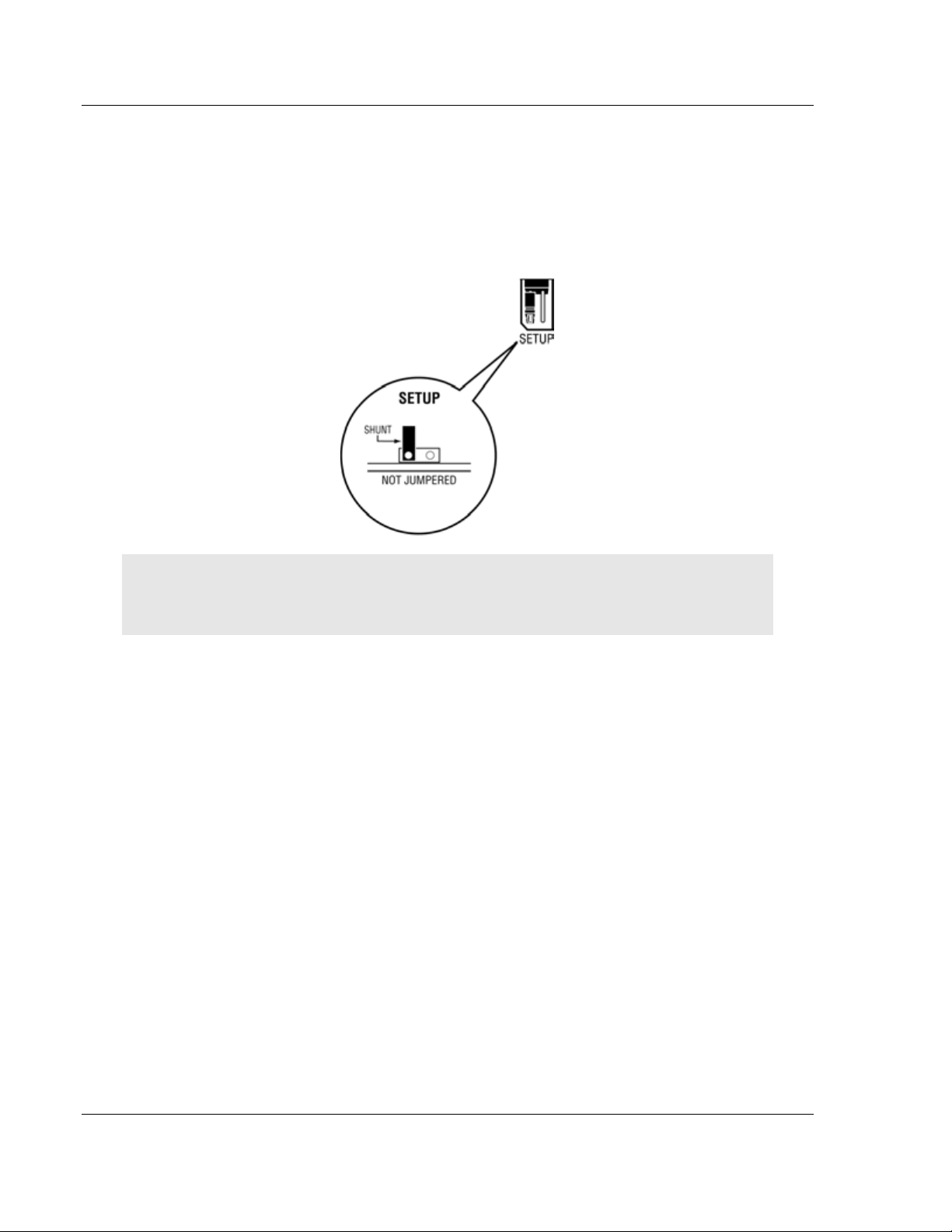
The following illustration shows the MVI71-DFNT jumper configuration.
Note: If you are installing the module in a remote rack, you may prefer to leave the Setup pins
jumpered. That way, you can update the module’s firmware without requiring physical access to
the module.
Page 14 of 175 ProSoft Technology, Inc.
February 3, 2011
Page 15

MVI71-DFNT ♦ PLC 5 Start Here
EtherNet/IP Client/Server Communication Module User Manual
1.4 Install the Module in the Rack
If you have not already installed and configured your PLC processor and power
supply, please do so before installing the MVI71-DFNT module. Refer to your
Rockwell Automation product documentation for installation instructions.
Warning: You must follow all safety instructions when installing this or any other electronic
devices. Failure to follow safety procedures could result in damage to hardware or data, or even
serious injury or death to personnel. Refer to the documentation for each device you plan to
connect to verify that suitable safety procedures are in place before installing or servicing the
device.
After you have checked the placement of the jumpers, insert MVI71-DFNT into
the PLC™ chassis. Use the same technique recommended by Rockwell
Automation to remove and install PLC modules.
Warning: This module is not hot-swappable! Always remove power from the rack before
inserting or removing this module, or damage may result to the module, the processor, or other
connected devices.
1 Turn power OFF.
2 Align the module with the top and bottom guides, and slide it into the rack
until the module is firmly against the backplane connector.
3 With a firm but steady push, snap the module into place.
4 Check that the holding clips on the top and bottom of the module are securely
in the locking holes of the rack.
5 Make a note of the slot location. You will need to identify the slot in which the
module is installed in order for the sample program to work correctly. Slot
numbers are identified on the green circuit board (backplane) of the PLC
rack.
6 Turn power ON.
Note: If you insert the module improperly, the system may stop working, or may behave
unpredictably.
ProSoft Technology, Inc. Page 15 of 175
February 3, 2011
Page 16
Start Here MVI71-DFNT ♦ PLC 5
User Manual EtherNet/IP Client/Server Communication Module
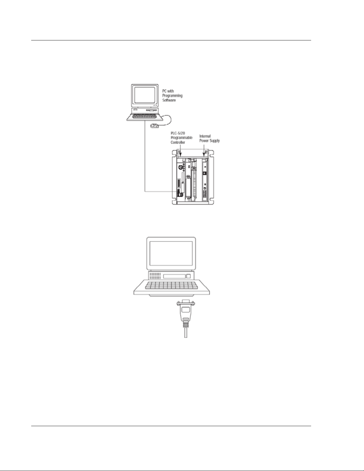
1.5 Connect your PC to the Processor
1 Connect the right-angle connector end of the cable to your controller at the
communications port.
2 Connect the straight connector end of the cable to the serial port on your
computer.
Page 16 of 175 ProSoft Technology, Inc.
February 3, 2011
Page 17
MVI71-DFNT ♦ PLC 5 Start Here
EtherNet/IP Client/Server Communication Module User Manual
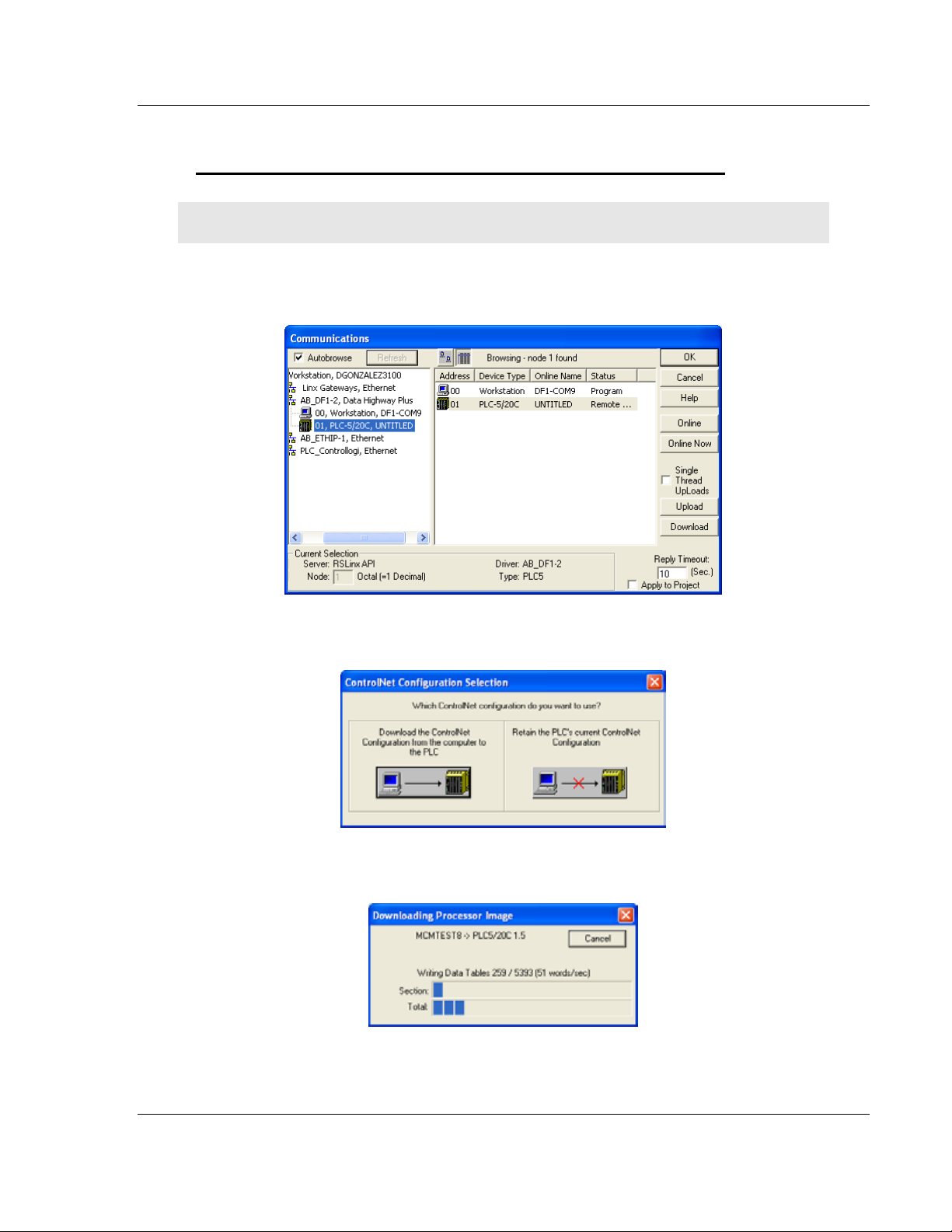
1.6 Download the Sample Program to the Processor
To download the sample program from RSLogix 5 to the PLC processor
Note: The key switch on the front of the PLC processor must be in the REM position.
1 If you are not already online to the processor, open the Communications
menu, and then choose Download. RSLogix will establish communication
with the processor.
2 Click the Download button to transfer the sample program to the processor.
3 When prompted, choose Computer to PLC
4 RSLogix will compile the program and transfer it to the processor. This
process may take a few minutes.
ProSoft Technology, Inc. Page 17 of 175
February 3, 2011
Page 18
Start Here MVI71-DFNT ♦ PLC 5
User Manual EtherNet/IP Client/Server Communication Module
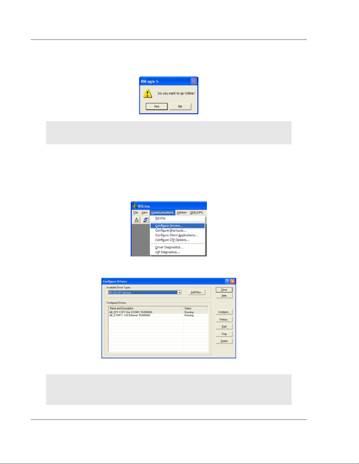
5 When the download is complete, RSLogix will open another confirmation
dialog box. Click OK to switch the processor from Program mode to Run
mode.
Note: If you receive an error message during these steps, refer to your RSLogix documentation to
interpret and correct the error.
1.6.1 Configuring the RSLinx Driver for the PC COM Port
If RSLogix is unable to establish communication with the processor, follow these
steps.
1 Open RSLinx.
2 Open the C
OMMUNICATIONS menu, and choose CONFIGURE DRIVERS.
This action opens the Configure Drivers dialog box.
Note: If the list of configured drivers is blank, you must first choose and configure a driver from the
Available Driver Types list. The recommended driver type to choose for serial communication with
the processor is RS-232 DF1 Devices.
Page 18 of 175 ProSoft Technology, Inc.
February 3, 2011
Page 19
MVI71-DFNT ♦ PLC 5 Start Here
EtherNet/IP Client/Server Communication Module User Manual
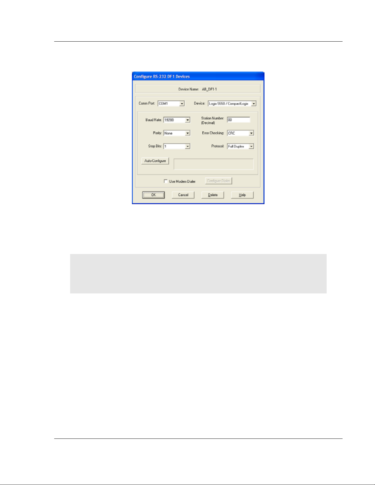
3 Click to select the driver, and then click CONFIGURE. This action opens the
Configure RS-232 DF1 Devices dialog box.
4 Click the AUTO-CONFIGURE button. RSLinx will attempt to configure your
serial port to work with the selected driver.
5 When you see the message Auto Configuration Successful, click the OK
button to dismiss the dialog box.
Note: If the auto-configuration procedure fails, verify that the cables are connected correctly
between the processor and the serial port on your computer, and then try again. If you are still
unable to auto-configure the port, refer to your RSLinx documentation for further troubleshooting
steps.
ProSoft Technology, Inc. Page 19 of 175
February 3, 2011
Page 20
Start Here MVI71-DFNT ♦ PLC 5
User Manual EtherNet/IP Client/Server Communication Module
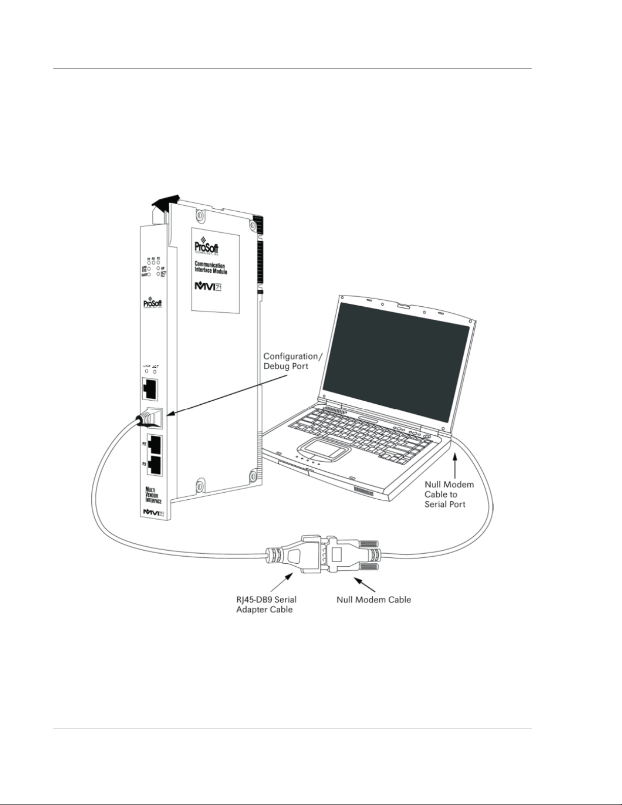
1.7 Connect your PC to the Module
With the module securely mounted, connect your PC to the Configuration/Debug
port using an RJ45-DB-9 Serial Adapter Cable and a Null Modem Cable.
1 Attach both cables as shown.
2 Insert the RJ45 cable connector into the Configuration/Debug port of the
module.
3 Attach the other end to the serial port on your PC.
Page 20 of 175 ProSoft Technology, Inc.
February 3, 2011
Page 21

MVI71-DFNT ♦ PLC 5 Installing and Configuring the Module
EtherNet/IP Client/Server Communication Module User Manual
2 Installing and Configuring the Module
In This Chapter
Module Configuration
Configuration File .................................................................................. 24
IP Address ............................................................................................. 38
Uploading and Downloading the Configuration File ............................... 39
Module Data .......................................................................................... 41
............................................................................ 23
This chapter describes how to install and configure the module to work with your
application. The configuration process consists of the following steps.
1 Modify the module’s configuration files to meet the needs of your application,
and copy the updated configuration to the module. Example configuration
files are provided on the CD-ROM. Refer to the Modifying the Example
Configuration File section, later in this chapter, for more information on the
configuration files.
2 Modify the example ladder logic to meet the needs of your application, and
copy the ladder logic to the processor. Example ladder logic files are provided
on the CD-ROM.
Note: If you are installing this module in an existing application, you can copy the necessary
elements from the example ladder logic into your application.
ProSoft Technology, Inc. Page 21 of 175
February 3, 2011
Page 22

Installing and Configuring the Module MVI71-DFNT ♦ PLC 5
User Manual EtherNet/IP Client/Server Communication Module
The rest of this chapter describes these steps in more detail.
Set up of the MVI71-DFNT module requires software configuration using the
RSLogix 5 program and the DFNT.CFG file on the Compact Flash Disk in the
module. The easiest method to implement the module is to start with the
appropriate example provided with the module MVI71DFNT_BT.RSP for the
block transfer interface and the default configuration file. If you are installing this
module in an existing application, you can copy the elements required from the
example ladder logic to your application.
It is now time to edit the DFNT.CFG file to set up the module for the specific
application. Refer to the Configuration File section of this document. Download
this configuration to the module along with the associated ladder logic.
Enter the ladder logic to handle the blocks transferred between the module and
the PLC. Download the program to the PLC and test the program with the
module.
The module is now set up and ready for your application. Insert the module in the
rack (with the power turned off) and attach the serial communication cables.
Download the new application to the controller and place the processor in run
mode. Download the new DFNT.CFG file to the module using a terminal
emulation program. If all the configuration parameters are set correctly and the
module is attached to a network, the module’s Application LED (APP LED)
should remain off and the backplane activity LED (BP ACT) should blink very
rapidly. Refer to Diagnostics and Troubleshooting if you encounter errors. Attach
a computer or terminal to Port 0 on the module and look at the status of the
module using the Configuration/Debug Menu in the module.
Page 22 of 175 ProSoft Technology, Inc.
February 3, 2011
Page 23

MVI71-DFNT ♦ PLC 5 Installing and Configuring the Module
EtherNet/IP Client/Server Communication Module User Manual
2.1 Module Configuration
This section contains the setup procedure, data, and ladder logic for successful
application of the MVI71-DFNT module. Each step in the setup procedure is
defined in order to simplify the use of the module.
2.1.1 Obtain the Sample Configuration Files
The ProSoft Solutions CD is organized in folders by module name. In the folder
for the module you are using, you will find sample configuration files and other
information.
1 Use Windows Explorer to locate the sample configuration files for your MVI71
module on the MVI71 CD.
2 When you have located the correct configuration files, use the C
P
ASTE commands to move the files to a location on your PC’s hard drive. We
recommend C:\temp.
3 Files copied from a CD-ROM are read-only. You must make the files writable.
Navigate to the directory where you copied the files, then select the files and
click the right mouse button to open a shortcut menu. On the shortcut menu,
select P
4 Next, open the configuration files in a text editor such as Notepad, which
comes with Windows. To start Notepad, click the S
choose P
5 When Notepad starts, open the F
to the folder where you copied the configuration file on your PC and select
the file. Click O
editing.
ROPERTIES, and clear (uncheck) the READ ONLY check box.
ROGRAMS / ACCESSORIES / NOTEPAD.
PEN. The configuration file will open in Notepad, ready for
OPY and
TART button, and then
ILE menu, and then choose OPEN. Navigate
Note: We do not recommend opening the configuration file in a word processor such as Microsoft
Word, because the file may be saved in a format that cannot be read by the module.
ProSoft Technology, Inc. Page 23 of 175
February 3, 2011
Page 24

Installing and Configuring the Module MVI71-DFNT ♦ PLC 5
User Manual EtherNet/IP Client/Server Communication Module
2.2 Configuration File
In order for the module to operate, a configuration file (DFNT.CFG) is required.
This configuration file contains information to set the data transfer characteristics
between the module and the processor, to configure the module's client and
command list, and to configure the pass-through features. Each parameter in the
file must be set carefully in order for the application to be implemented
successfully.
The configuration file is separated into sections with topic header names
enclosed in the [ ] characters. The configuration file consists of the following
sections:
[Section] Description
[Module] General module configuration information
[DFNT Client 0] Configuration for the DFNT client
[DFNT Client 0 Commands] Command list for the DFNT client
[DF1 Pass-Through Server Port 1] Parameters for the pass-through port of the second port
[DF1 Pass-Through Port] Parameters for the DF1 port emulated on the third port of
After each section header, the file contains a set of parameters. Unique labels
are used under each section to specify a parameter. Each label in the file must
be entered exactly as shown in the file for the parameter to be identified by the
program. If the module is not considering a parameter, look at the label for the
data item. Each parameter's value is separated from the label with the ":"
character. This character is used by the program to delimit the position in the
data record where to start reading data. All data for a parameter must be placed
after the ":" character. For numeric parameter values any text located after the
value will not be used. There must be at least one space character between the
end of the parameter value and the following text.
Any record that begins with the "#" character is considered to be a comment
record. These records can be placed anywhere in the file as long as the "#"
character is found in the first column of the line. These lines are ignored in the
file and can be used to provide documentation within the configuration file.
Liberal use of comments within the file can ease the use and interpretation of the
data in the file.
The client command list section is formatted differently than the other sections.
These sections contain lists of parameters to be used. Each list begins with the
label START and when the END label is reached. When entering the records into
the list, make certain that the first character in each line is left blank.
The [DFNT CLIENT 0 COMMANDS] section defines the Ethernet/IP commands
to be issued from the module to server devices on the network. These
commands can be used for data collection and/or control of devices on the
TCP/IP network.
on the module
the module
Page 24 of 175 ProSoft Technology, Inc.
February 3, 2011
Page 25

MVI71-DFNT ♦ PLC 5 Installing and Configuring the Module
EtherNet/IP Client/Server Communication Module User Manual
2.2.1 [Module]
This section provides the module with a unique name, identifies the method of
failure for the communications for the module if the processor is not in run, and
describes how to initialize the module upon startup.
Module Name
0 to 80 characters
This parameter assigns a name to the module that can be viewed using the
configuration/debug port. Use this parameter to identify the module and the
configuration file.
Read Register Start
0 to 3999
This parameter specifies the starting register address of a block of data registers
to transfer from the module to the processor.
Read Register Count
0 to 3960
This parameter specifies the number of registers to be transferred from the
module to the processor.
Write Register Start
0 to 3999
This parameter specifies the starting register address of a module register block
where data transferred from the processor will be stored.
Write Register Count
0 to 3960
This parameter specifies the number of registers to transfer from the processor to
the module.
Failure Flag Count
0 through 65535
This parameter specifies the number of successive transfer errors that must
occur before halting communication on the application port(s). If the parameter is
set to 0, the application port(s) will continue to operate under all conditions. If the
value is set larger than 0 (1 to 65535), communications will cease if the specified
number of failures occur.
ProSoft Technology, Inc. Page 25 of 175
February 3, 2011
Page 26

Installing and Configuring the Module MVI71-DFNT ♦ PLC 5
User Manual EtherNet/IP Client/Server Communication Module
Initializing Output Data
YES or NO
This parameter determines if the output data for the module should be initialized
with values from the processor. If the value is set to N
be initialized to 0. If the value is set to Y
ES (1), the data will be initialized with
O (0), the output data will
data from the processor. Use of this option requires associated ladder logic to
pass the data from the processor to the module.
DFNT Server File Size
100 or 1000
Sets the maximum file size (100 or 1000) for the servers
2.2.2 [DF1 Pass-Through Server Port 1]
This section is used to define the DF1 pass-through server on Port 1 (the second
port)
[DF1 Pass-Through Server Port 1]
Enabled : Yes #Y=Use server, N=Do not use server
Service Port Number : 15000 #TCP service port for this server
Busy Timeout : 500 #Time to wait for not Busy (100-65535
milliseconds)
Baud Rate : 19200 #Baud rate for port 110-19200
Parity : N #N=None,O=Odd,E=Even,M=Mark,S=Space
Data Bits : 8 #5, 6, 7 or 8
Stop Bits : 1 #1 or 2
Enabled
Yes or No
This parameter determines if the server will be utilized by the module. If a value
of "Yes" is entered, the server will be used. Any other value will disable the
server.
Service Port Number
1 to 65535
This parameter sets the TCP/IP service port for this server. Each server can
have its own unique service port or can share the same number with other
servers.
Busy Timeout
100 to 65535 milliseconds
This parameter sets the number of milliseconds the server will wait for the serial
pass-through port to become available. Valid data range for this parameter is 100
to 65535.
Page 26 of 175 ProSoft Technology, Inc.
February 3, 2011
Page 27

MVI71-DFNT ♦ PLC 5 Installing and Configuring the Module
EtherNet/IP Client/Server Communication Module User Manual
Baud Rate - 110 to 19200
110 to 19200
This parameter specifies the baud rate for the primary port on the module. Baud
rate entries are 110, 150, 300, 600, 1200, 2400, 4800, 9600 or 19200
Parity
None, Odd, Even
Parity is a simple error checking algorithm used in serial communication. This
parameter specifies the type of parity checking to use.
All devices communicating through this port must use the same parity setting.
Data Bits
5, 6, 7 or 8
This parameter sets the number of data bits for each word used by the protocol.
All devices communicating through this port must use the same number of data
bits.
Stop Bits
1 or 2
Stop bits signal the end of a character in the data stream. For most applications,
use one stop bit. For slower devices that require more time to re-synchronize,
use two stop bits.
All devices communicating through this port must use the same number of stop
bits.
2.2.3 [DF1 Pass-Through Port]
This section is used to define the configuration for the DF1 pass-through port on
Port 2 (the third port)
[DF1 Pass-Through Port]
Enabled : Y #Y=Use port, N=Do not use port
Local Station ID : 1 #DF1 node address
Protocol : H #F=Full-Duplex, H=Half-Duplex
Termination Type : CRC #B=BCC, C=CRC
Baud Rate : 38400 #Baud rate for port 1200-38400
Parity : None #N=None,O=Odd,E=Even,M=Mark,S=Space
Data Bits : 8 #5, 6, 7 or 8
Stop Bits : 1 #1 or 2
RTS On : 0 #0-65536 mSec before message
RTS Off : 0 #0-65536 mSec after message
Use CTS Line : N #Use CTS modem control line (Y/N)
Retry Count : 3 #Response failure retry count
Request Timeout : 500 #Request message timeout (0-10000 mSec)
Busy Timeout : 500 #Port Busy timeout (0-10000 mSec)
ProSoft Technology, Inc. Page 27 of 175
February 3, 2011
Page 28

Installing and Configuring the Module MVI71-DFNT ♦ PLC 5
User Manual EtherNet/IP Client/Server Communication Module
Enabled
Yes or No
This parameter determines if the server will be utilized by the module. If a value
of "Yes" is entered, the server will be used. Any other value will disable the
server.
Local Station ID
0 to 254
This parameter specifies the local station ID for all DF1 messages sent to this
port. A value of 255 is not permitted as this is the broadcast address. The
application will only accept messages with this node address.
Protocol
F (Full duplex) or H (Half duplex)
The value selected should match that set for the PLC processor.
Termination Type
BCC or CRC
This parameter specifies the error checking for all DF1 messages. Enter BCC or
CRC.
Baud Rate - 1200 to 38400
1200 to 38400
This is the baud rate to be used for the port. Enter the baud rate as a value. Baud
rate entries are 1200, 2400, 4800, 9600, 19200, 28800 or 38400.
Parity
None, Odd, Even, Mark, Space
Parity is a simple error checking algorithm used in serial communication. This
parameter specifies the type of parity checking to use.
All devices communicating through this port must use the same parity setting.
Data Bits
5, 6, 7 or 8
This parameter sets the number of data bits for each word used by the protocol.
All devices communicating through this port must use the same number of data
bits.
Page 28 of 175 ProSoft Technology, Inc.
February 3, 2011
Page 29

MVI71-DFNT ♦ PLC 5 Installing and Configuring the Module
EtherNet/IP Client/Server Communication Module User Manual
Stop Bits
1 or 2
Stop bits signal the end of a character in the data stream. For most applications,
use one stop bit. For slower devices that require more time to re-synchronize,
use two stop bits.
All devices communicating through this port must use the same number of stop
bits.
RTS On
0 to 65535 milliseconds
This parameter sets the number of milliseconds to delay after Ready To Send
(RTS) is asserted before data will be transmitted.
RTS Off
0 to 65535 milliseconds
This parameter sets the number of milliseconds to delay after the last byte of
data is sent before the RTS modem signal will be set low.
Use CTS Line
YES or NO
This parameter specifies if the Clear To Send (CTS) modem control line is to be
used or not. If the parameter is set to N
the parameter is set to Y
ES, the CTS line will be monitored and must be high
O, the CTS line will not be monitored. If
before the module will send data. Normally, this parameter is required when halfduplex modems are used for communication (2-wire). This procedure is
commonly referred to as hardware handshaking.
Retry Count
0 to 10
This parameter specifies the number of times a command will be retried if it fails.
Request Timeout
0 to 10000 milliseconds
This parameter specifies the number of milliseconds to wait for a complete
request message. The timer is started after the DLE-STX character sequence is
received for the full-duplex protocol or the DLE-SOH sequence for the halfduplex protocol. If the timer expires, the current request message will be aborted.
Busy Timeout
0 to 10000 milliseconds
This parameter specifies the number of milliseconds to wait for the pass-through
port to become available.
ProSoft Technology, Inc. Page 29 of 175
February 3, 2011
Page 30

Installing and Configuring the Module MVI71-DFNT ♦ PLC 5
User Manual EtherNet/IP Client/Server Communication Module
ACK Timeout
0 to 10000 milliseconds
This parameter specifies the number of milliseconds to wait for a DLE-ACK
character sequence after a response is issued.
2.2.4 [DFNT Client 0]
This section is used to define the configuration for the master device simulated
on network port
[DFNT Client 0]
Minimum Command Delay : 30 #Minimum number of msec’s between commands
Response Timeout : 1000 #Response message timeout (0-5000 mSec)
Retry Count : 3 #Response failure retry count
Minimum Command Delay
0 to 65535 milliseconds
This parameter specifies the number of milliseconds to wait between the initial
issuances of a command. This parameter can be used to delay all commands
sent to servers to avoid "flooding" commands on the network. This parameter
does not affect retries of a command as they will be issued when failure is
recognized.
Response Timeout
0 to 65535 milliseconds
This is the time in milliseconds that a Client will wait before re-transmitting a
command if no response is received from the addressed server. The value to use
depends on the type of communication network used, and the expected
response time of the slowest device on the network.
Retry Count
0 to 10
This parameter specifies the number of times a command will be retried if it fails.
Page 30 of 175 ProSoft Technology, Inc.
February 3, 2011
Page 31

MVI71-DFNT ♦ PLC 5 Installing and Configuring the Module
EtherNet/IP Client/Server Communication Module User Manual
2.2.5 [DFNT Client x Commands]
This section defines the EtherNet/IP commands to be issued from the module to
server devices on the network. These commands can be used for data collection
and/or control of devices on the TCP/IP network.
ProSoft Technology, Inc. Page 31 of 175
February 3, 2011
Page 32

Installing and Configuring the Module MVI71-DFNT ♦ PLC 5
User Manual EtherNet/IP Client/Server Communication Module
Command List
In order to interface the virtual database with DF1 slave devices, you must
construct a command list. The commands in the list specify the DF1 slave device
to be utilized, the function to be performed (read or write), the data area in the
device to interface with and the position in the virtual database to be associated
with the device data. There is a separate command list for each DF1 master
device emulated. The list is processed from top (command #0) to bottom. A poll
interval parameter is associated with each command to specify a minimum delay
time between the issuance of a command. If the user specifies a value of 10 for
the parameter, the command will be executed no more frequently than every 10
seconds for the serial implementation and 1 second for the network
implementation.
Write commands have a special feature, as they can be set to execute only if the
data in the write command changes. If the data in the command has not changed
since the command was last issued, the command will not be executed. If the
data in the command has changed since the command was last issued, the
command will be executed. Use of this feature can lighten the load on the DF1
network. In order to implement this feature; set the enable code for the command
to a value of 2.
If the module is configured for the serial DF1 half-duplex protocol, the module
can act as a master device routing messages between attached slave devices.
This peer-to-peer communication is defined in the DF1 protocol specification.
The master polls each DF1 slave device until no more data is available from the
device. Response messages from the slaves that have a destination address that
do not match the module are routed with a request message header back out
onto the network. This facility offers communication between the slave devices
for control and data monitoring. This feature is not available if the module is
configured for DF1 full-duplex mode (point-to-point).
The module supports numerous commands. This permits the module to interface
with a wide variety of DF1 protocol devices. This includes PLC2, PLC5, SLC-500
series, MicroLogix and ControlLogix processors. Additionally, other devices
supplied by Rockwell Automation that use the DF1 protocol are supported.
The format of each command in the list depends on the function being executed.
To simplify command construction, the module uses its own set of function codes
to associate a command with a DF1 command/function type. The tables below
list the functions supported by the module:
Basic Command Set Functions
Function
Code
1 0x00 N/A Protected Write X
2 0x01 N/A Unprotected Read X X
3 0x02 N/A Protected Bit Write X
4 0x05 N/A Unprotected Bit Write X
5 0x08 N/A Unprotected Write X X
Command Function Definition PLC5 SLC500 &
MicroLogix
Powermonitor II
ControlLogix
X
X
X
X
X
Page 32 of 175 ProSoft Technology, Inc.
February 3, 2011
Page 33

MVI71-DFNT ♦ PLC 5 Installing and Configuring the Module
X
X
X
EtherNet/IP Client/Server Communication Module User Manual
PLC-5 Command Set Functions
Function
Code
100 0x0F 0x00 Word Range Write
Command Function Definition PLC5 SLC500 &
MicroLogix
X
Powermonitor II
X
ControlLogix
(Binary Address)
101 0x0F 0x01 Word Range Read
X
X
(Binary Address)
102 0x0F 0x26 Read-Modify-Write
X
X
(Binary Address)
150 0x0F 0x00 Word Range Write
X
X
(ASCII Address)
151 0x0F 0x01 Word Range Read
X
X
(ASCII Address)
152 0x0F 0x26 Read-Modify-Write
SLC-500 Command Set Functions
Function
Command Function Definition PLC5 SLC500 &
(ASCII Address)
Code
501 0x0F 0xA1 Protected Typed
X
MicroLogix
X
Powermonitor II
ControlLogix
X
Logical Read With
Two Address Fields
502 0x0F 0XA2 Protected Typed
X X X
Logical Read With
Three Address Fields
509 0x0F 0XA9 Protected Typed
X
Logical Write With
Two Address Fields
510 0x0F 0XAA Protected Typed
X X X
Logical Write With
Three Address Fields
511 0x0F 0XAB Protected Typed
X
Logical Write With
Mask (Three Address
Fields)
Each command list record has the same general format. The first part of the
record contains the information relating to the communication module and the
second part contains information required to interface to the DF1 or EtherNet/IP
slave device.
ProSoft Technology, Inc. Page 33 of 175
February 3, 2011
Page 34

Installing and Configuring the Module MVI71-DFNT ♦ PLC 5
Module Information Data
Device Information Data
Functio
Enabl
Internal
Poll
Count Swap
IP
Slot
Funct
Function Parameters
FC 5
Code
Register
Second
Count
Code
Node 5
Word
FC 100
Code
Register
Second
Count
Code
Node 100
File
Elemen
Sub-
FC 102
Code
Register
Second
Count
Code
Node 102
File
Elemen
SubFC 152
Code
Register
Second
Count
Code
Node 152
File
FC 501
Code
Register
Second
Count
Code
Node 501
File
File
Elemen
FC 509
Code
Register
Second
Count
Code
Node 509
File
File
Elemen
FC 511
Code
Register
Second
Count
Code
Node 511
File
File
Elemen
Sub-
User Manual EtherNet/IP Client/Server Communication Module
Command Entry Formats
The format of each command in the list depends on the function being executed.
Refer to Command Function Codes (page
34) for a complete discussion of the
commands supported by the module and of the structure and content of each
command.
The following table shows the structure of the configuration data necessary for
each of the supported commands.
Column # 1 2 3 4 5 6 7 8 9 10 11 12
n Code
FC 1 Code Register Seconds Count Code Node Slot 1 Word
FC 2 Code Register Seconds Count Code Node 2 Word
FC 3 Code Register Seconds Count Code Node 3 Word
FC 4 Code Register Seconds Count Code Node 4 Word
e
Code
Addres
s
Interval
Time
s
Code
Address
Numbe
r
ion
Code
Address
Address
Address
Address
Address
s
FC 101 Code Register Seconds Count Code Node 101 File
s
FC 150 Code Register Seconds Count Code Node 150 File
FC 151 Code Register Seconds Count Code Node 151 File
s
s
FC 502 Code Register Seconds Count Code Node 502 File
s
FC 510 Code Register Seconds Count Code Node 510 File
Number
Number
Number
String
String
String
Type
Type
Type
Type
t
Element Sub-
t
Numbe
r
File
Numbe
r
Numbe
r
File
Numbe
r
Elemen
t
Elemen
t
Elemen
t
t
Element Sub-
t
Element Sub-
Elemen
t
Elemen
t
Page 34 of 175 ProSoft Technology, Inc.
February 3, 2011
s
Type
Numbe
r
t
Elemen
t
Page 35
MVI71-DFNT ♦ PLC 5 Installing and Configuring the Module
EtherNet/IP Client/Server Communication Module User Manual
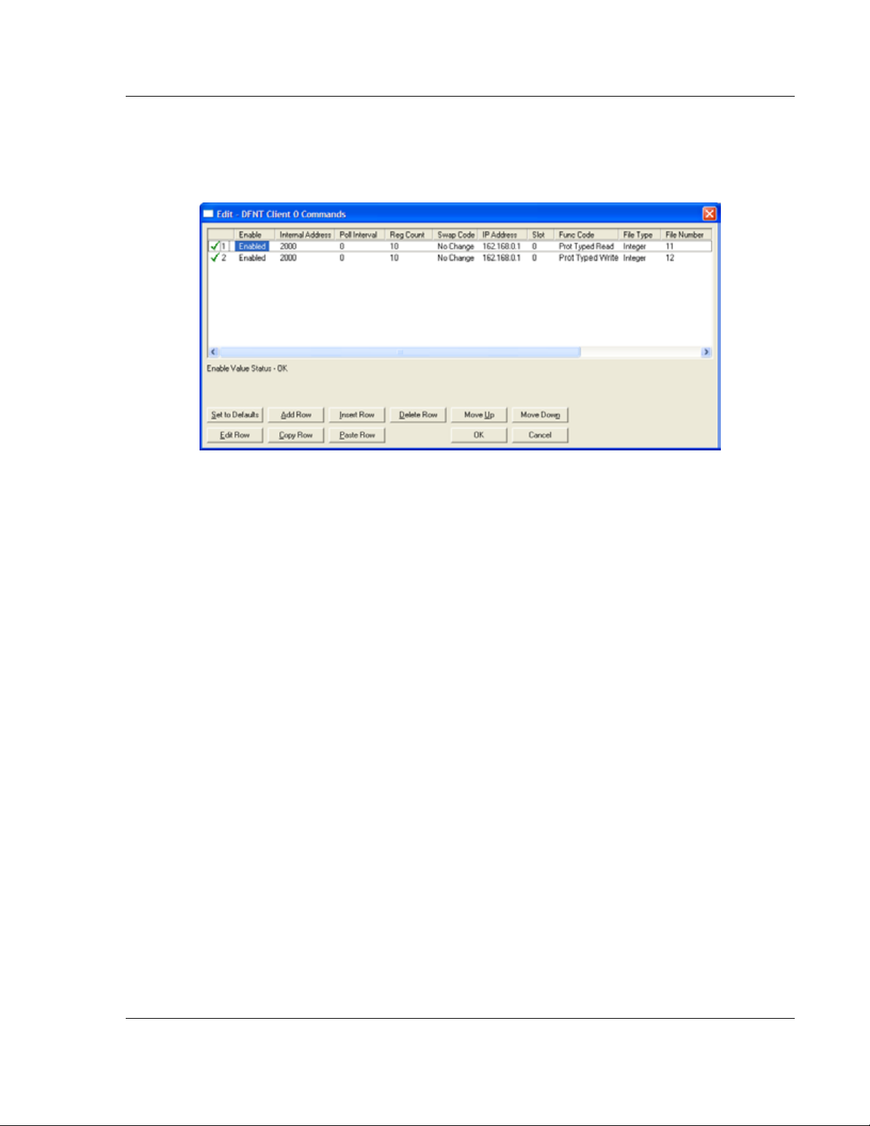
The first part of the record is the Module Information, which relates to the
module. The second part contains information required to interface to the Server
device. An example of a command list section of the configuration file is shown in
the following illustration.
[DFNT Client 0 Commands]
#
# The file contains examples for a ControlLogix processor with the N7 file
# configured. This example uses SLC and PLC5 commands.
#
# LOCATION :
# DATE : 04/05/2000
# CONFIGURED BY: RAR
# MODIFIED :
#
# 1 2 3 4 5 6 7 8 9 10 11 12
# DB Poll Swap Func File File Elm Sub
#Enab Addr Delay Count Code Node IP Address Slot Code Type # # Elm
START
# 1 2000 0 10 0 192.168.0.100 0 501 N 11 0
# 1 2000 0 10 0 192.168.0.100 0 509 N 12 0
#
# DB Poll Swap Func File Elm Sub
#Enab Addr Delay Count Code Node IP Address Slot Code # # Elm
END
ProSoft Technology, Inc. Page 35 of 175
February 3, 2011
Page 36

Installing and Configuring the Module MVI71-DFNT ♦ PLC 5
User Manual EtherNet/IP Client/Server Communication Module
The following table describes each parameter
Parameter Range Description
Enable 0, 1, 2 This field defines whether the command is to be executed and under what
conditions.
Value Description
0 The command is disabled and will not be executed in the normal
polling sequence.
1 The command is executed each scan of the command list if the
Poll Interval Time is set to zero. If the Poll Interval time is set, the
command is executed when the interval timer expires.
2 The command executes only if the internal data associated with
the command changes. This value is valid for write commands
Internal
Address
0 to 3999 This field specifies the database address in the module's internal database to
be associated with the command. If the command is a read function, the data
received in the response message is placed at the specified location. If the
command is write function, data used in the command is sourced from the
specified data area.
Poll Delay 0 to 1000 This parameter specifies the minimum interval to execute continuous
commands (Enable code of 1). The parameter is entered in 1/10th of a
second. Therefore, if a value of 100 is entered for a command, the command
executes no more frequently than every 10 seconds.
Count Command dependent. This parameter specifies the number of registers or digital points to be
associated with the command. See Command Function Codes (page 34) for
information
Swap Code 0, 1, 2, 3 This parameter defines if the data received from the Server is to be ordered
differently than that received from the Server device. This parameter is helpful
when dealing with floating-point or other multi-register values, as there is no
standard method of storage of these data types in Server devices. This
parameter can be set to order the register data received in an order useful by
other applications. The following table defines the values and their associated
operations:
Swap Code Description
0 None - No Change is made in the byte ordering (1234 =
1 Words - The words are swapped (1234=3412)
2 Words & Bytes - The words are swapped then the bytes in
3 Bytes - The bytes in each word are swapped (1234=2143)
The words should be swapped only when using an even number of words.
Node IP
xxx.xxx.xxx.xxx The IP address of the device being addressed by the command.
Address
Slot
When addressing a ControlLogix processor, the slot number corresponds to
the slot in the rack containing the controller being addressed. In the
ControlLogix platform, the controller can be placed in any slot and the rack
may contain multiple processors. This parameter uniquely selects a controller
in the rack.
Use a value of -1 when interfacing to an SLC 5/05 or a
PLC5. These devices do not have a slot number.
only.
1234)
each word are swapped (1234=4321)
Page 36 of 175 ProSoft Technology, Inc.
February 3, 2011
Page 37

MVI71-DFNT ♦ PLC 5 Installing and Configuring the Module
EtherNet/IP Client/Server Communication Module User Manual
Parameter Range Description
Function Code See Command
Function Codes (page
34)
Function
Parameters
See Command
Function Codes (page
34)
These parameters specify the function to be executed by the command. The
Reference chapter in this manual describes the meaning of these values for
each of the available supported commands. Following is a complete list of the
command supported by the Client driver.
Function Code Listing
Basic Command Set
1 Protected Write
2 Unprotected Read
3 Protected Bit Write
4 Unprotected Bit Write
5 Unprotected Write
PLC-5 Command Set (0x0F)
100 Word Range Write (Binary Address)
101 Word Range Read (Binary Address)
102 Read-Modify-Write (Binary Address)
150 Word Range Write (ASCII Address)
151 Word Range Read (ASCII Address)
152 Read-Modify-Write (ASCII Address)
SLC Command Set (0x0F)
501 Prot Typed Read with 2 addr fields
502 Prot Typed Read with 3 addr fields
509 Prot Typed Write with 2 addr fields
510 Prot Typed Write with 3 addr fields
511 Prot Type Write with Mask 3 addr field
The number of auxiliary parameters required depends on the function code
selected for the command.
ProSoft Technology, Inc. Page 37 of 175
February 3, 2011
Page 38

Installing and Configuring the Module MVI71-DFNT ♦ PLC 5
User Manual EtherNet/IP Client/Server Communication Module
2.3 IP Address
In addition to the DFNT.CFG, the MVI71-DFNT module requires a second
configuration file that identifies its Ethernet configuration. Without this
configuration file, the module will not communicate properly on the network.
This file contains the Ethernet address information to be used by the module and
may be transferred to and from the module from the Network command
available on the debug port of the module. Please consult your network
administrator for the correct settings for your network before placing this or any
other Ethernet TCP/IP device upon your network.
Important: If the field "my_ip" does not exist, or if the wattcp.cfg file is corrupted or does not exist,
the module will not function.
To set the Module’s IP Address
1 Locate the sample configuration files for your module on the ProSoft
Solutions CD.
2 Copy the configuration files and ladder to a location on your PC’s hard drive.
We recommend C:\temp.
3 After you move the files, right-click on each of the files, choose Properties,
and clear the READ ONLY check box.
4 Start Notepad.exe, or any other editor that can save plain text files.
5 Open the file WATTCP.CFG. The following example shows the contents of a
typical WATTCP.CFG file.
# ProSoft Technology
# Default private class 3 address
my_ip=192.168.0.100
# Default class 3 network mask
netmask=255.255.255.0
# The gateway I wish to use
gateway=192.168.0.1,192.168.0.0,255.255.255.0
6 Edit the file, using the IP addresses supplied by your network administrator.
Important: The module does not support DHCP (Dynamic Host Configuration Protocol) for
obtaining an IP address from a server. This module must have its own static IP address that does
not duplicate the IP address of any other device on the Ethernet network.
7 Save the file as WATTCP.CFG. You must now transfer the file to the module.
Refer to Transferring WATTCP.CFG to the module (page 40, page 61) for the
correct procedure.
Page 38 of 175 ProSoft Technology, Inc.
February 3, 2011
Page 39

MVI71-DFNT ♦ PLC 5 Installing and Configuring the Module
EtherNet/IP Client/Server Communication Module User Manual
2.4 Uploading and Downloading the Configuration File
ProSoft modules are shipped with a pre-loaded configuration file. In order to edit
this file, you may transfer the file from the module to your PC or locate and load
the file from the distribution CD-ROM supplied with the module. After editing, you
must transfer the file back to the module for your changes to take effect.
This section describes these procedures.
Important: The illustrations of configuration/debug menus in this section are intended as a general
guide and may not exactly match the configuration/debug menus in your own module. For specific
information about the configuration/debug menus in your module, refer to The Configuration/Debug
Menu (page 51).
2.4.1 Required Software
In order to send and receive data over the serial port (COM port) on your
computer to the module, you must use a communication program (terminal
emulator). The following table lists communication programs that have been
tested by ProSoft Technology.
DOS ProComm, as well as several other terminal emulation programs
Windows 3.1 Terminal
Windows 95/98 HyperTerminal, ProSoft Configuration Builder (PCB)
Windows
NT/2000/XP/Vista/7
HyperTerminal, ProSoft Configuration Builder (PCB)
The module uses the Zmodem file transfer protocol to send and receive
configuration files from your module. If you use a communication program that is
not on the list above, please be sure that it supports Zmodem file transfers.
ProSoft Technology, Inc. Page 39 of 175
February 3, 2011
Page 40

Installing and Configuring the Module MVI71-DFNT ♦ PLC 5
User Manual EtherNet/IP Client/Server Communication Module
2.5 Installing ProSoft Configuration Builder Software
You must install the ProSoft Configuration Builder (PCB) software to configure
the module. You can always get the newest version of ProSoft Configuration
Builder from the ProSoft Technology website.
Installing ProSoft Configuration Builder from the ProSoft website
8 Open your web browser and navigate to http://www.prosoft-
technology.com/pcb
9 Click the DOWNLOAD HERE link to download the latest version of ProSoft
Configuration Builder.
10 Choose S
11 Save the file to your Windows Desktop, so that you can find it easily when
you have finished downloading.
12 When the download is complete, locate and open the file, and then follow the
instructions on your screen to install the program.
If you do not have access to the Internet, you can install ProSoft Configuration
Builder from the ProSoft Solutions Product CD-ROM, included in the package
with your module.
Installing ProSoft Configuration Builder from the Product CD-ROM
13 Insert the ProSoft Solutions Product CD-ROM into the CD-ROM drive of your
PC. Wait for the startup screen to appear.
14 On the startup screen, click PRODUCT DOCUMENTATION. This action opens a
Windows Explorer file tree window.
15 Click to open the U
and files you will need to set up and configure your module.
16 Double-click the S
PCB_*.
software on your PC. The information represented by the "*" character in the
file name is the PCB version number and, therefore, subject to change as
new versions of PCB are released.
AVE or SAVE FILE when prompted.
TILITIES folder. This folder contains all of the applications
ETUP CONFIGURATION TOOL folder, double-click the
EXE file and follow the instructions on your screen to install the
Note: Many of the configuration and maintenance procedures use files and other utilities on the
CD-ROM. You may wish to copy the files from the Utilities folder on the CD-ROM to a convenient
location on your hard drive.
Page 40 of 175 ProSoft Technology, Inc.
February 3, 2011
Page 41

MVI71-DFNT ♦ PLC 5 Installing and Configuring the Module
EtherNet/IP Client/Server Communication Module User Manual
2.6 Module Data
All data related to the MVI71-DFNT module is stored in a user defined data files.
It is the responsibility of the ladder logic programmer to construct all the data files
required by the program and to write the ladder logic required to interface to
these files.
ProSoft Technology, Inc. Page 41 of 175
February 3, 2011
Page 42

Installing and Configuring the Module MVI71-DFNT ♦ PLC 5
User Manual EtherNet/IP Client/Server Communication Module
Page 42 of 175 ProSoft Technology, Inc.
February 3, 2011
Page 43

MVI71-DFNT ♦ PLC 5 Ladder Logic
EtherNet/IP Client/Server Communication Module User Manual
3 Ladder Logic
Ladder logic is required for application of the MVI71-DFNT module. Tasks that
must be handled by the ladder logic are module data transfer, special block
handling, and status data receipt. Additionally, a power-up handler may be
needed to handle the initialization of the module’s data and to clear any
processor fault conditions.
The sample ladder logic, on the ProSoft Solutions CD-ROM, is extensively
commented, to provide information on the purpose and function of each rung. For
most applications, the sample ladder will work without modification.
ProSoft Technology, Inc. Page 43 of 175
February 3, 2011
Page 44

Ladder Logic MVI71-DFNT ♦ PLC 5
User Manual EtherNet/IP Client/Server Communication Module
Page 44 of 175 ProSoft Technology, Inc.
February 3, 2011
Page 45

MVI71-DFNT ♦ PLC 5 Diagnostics and Troubleshooting
EtherNet/IP Client/Server Communication Module User Manual
4 Diagnostics and Troubleshooting
In This Chapter
LED Status Indicators
The Configuration/Debug Menu ............................................................ 51
Reading Status Data from the Module .................................................. 63
............................................................................ 46
The module provides information on diagnostics and troubleshooting in the
following forms:
LED status indicators on the front of the module provide general information
on the module's status.
Status data contained in the module can be viewed through the
Configuration/Debug port, using the troubleshooting and diagnostic
capabilities of ProSoft Configuration Builder (PCB).
Status data values can be transferred from the module to processor memory
and can be monitored there manually or by customer-created logic.
ProSoft Technology, Inc. Page 45 of 175
February 3, 2011
Page 46

Diagnostics and Troubleshooting MVI71-DFNT ♦ PLC 5
User Manual EtherNet/IP Client/Server Communication Module
4.1 LED Status Indicators
The LEDs indicate the module’s operating status as follows:
LED Color Status Indication
CFG Green On Data is being transferred between the module and a remote
Off No data is being transferred on the Configuration/Debug
P1 Green On Data is being transferred between the module and the
Off No data is being transferred on this port
P2 Green On Data is being transferred on this port and the remote device
Off No data is being transferred on this port
APP Amber Off The MVI71-DFNT is working normally.
On The MVI71-DFNT module program has recognized an error.
BP ACT Amber On The LED is on when the module is performing a write
Off The LED is off when the module is performing a read
OK Red/
Green
BAT Red Off The battery voltage is OK and functioning.
Off The card is not receiving any power and is not securely
Green The module is operating normally.
Red
On The battery voltage is low or battery is not present. Allow
terminal using the Configuration/Debug port.
port.
processors Channel 0 port.
connected to the port
operation on the backplane.
operation on the backplane. Under normal operation, the
LED should blink rapidly on and off.
plugged into the rack.
The program has detected an error or is being configured. If
the LED remains red for over 10 seconds, the program has
probably halted. Remove the card from the rack and reinsert the card to restart the module’s program.
battery to charge by keeping module plugged into rack for
24 hours. If BAT LED still does not go off, contact ProSoft
Technology, as this is not a user serviceable item.
Page 46 of 175 ProSoft Technology, Inc.
February 3, 2011
Page 47

MVI71-DFNT ♦ PLC 5 Diagnostics and Troubleshooting
2 0x0004
EtherNet/IP Client/Server Communication Module User Manual
If a configuration error is found for the client, the client configuration error word
will have a value other than zero. The configuration error word bits have the
following definitions:
Bit Description Value
0 0x0001
1 0x0002
3 0x0008
4 Invalid retry count (0 to 10) 0x0010
5 0x0020
6 0x0040
7 0x0080
8 0x0100
9 0x0200
10 0x0400
11 0x0800
12 0x1000
13 0x2000
14 0x4000
15 0x8000
If a configuration error is present for the pass-through server, the configuration
error word contains a value other than zero. The configuration error word bits
have the following definitions:
Bit Description Value
0 Invalid enable code 0x0001
1 Invalid busytimeout setting (< 100 milliseconds) 0x0002
2 0x0004
3 0x0008
4 0x0010
5 Invalid baud rate 0x0020
6 Invalid parity 0x0040
7 Invalid data bits 0x0080
8 Invalid stop bits 0x0100
9 0x0200
10 0x0400
11 0x0800
12 0x1000
13 0x2000
14 0x4000
15 0x8000
ProSoft Technology, Inc. Page 47 of 175
February 3, 2011
Page 48

Diagnostics and Troubleshooting MVI71-DFNT ♦ PLC 5
User Manual EtherNet/IP Client/Server Communication Module
If a configuration error is present for the pass-through port, the configuration error
word contains a value other than zero. The configuration error word bits have the
following definitions:
Bit Description Value
0 Invalid enable code 0x0001
1 Invalid local station ID 0x0002
2 Invalid protocol or termination type 0x0004
3 Invalid baud rate 0x0008
4 Invalid parity 0x0010
5 Invalid data bits 0x0020
6 Invalid stop bits 0x0040
7 0x0080
8 Invalid Use CTS Line selection 0x0100
9 Invalid retry count 0x0200
10 0x0400
11 0x0800
12 0x1000
13 0x2000
14 0x4000
15 0x8000
Correct any invalid data in the configuration for proper module operation. When
the configuration contains a valid parameter set, all the bits in the configuration
words are clear. This does not indicate that the configuration is valid for the user
application. Make sure each parameter is set correctly for the specific
application.
Refer to the Configuration/Debug menu for configuration error words.
If the APP, BP ACT and OK LEDs blink at a rate of every one-second, this
indicates a serious problem with the module. Call ProSoft Technology support to
arrange for repairs.
Page 48 of 175 ProSoft Technology, Inc.
February 3, 2011
Page 49

MVI71-DFNT ♦ PLC 5 Diagnostics and Troubleshooting
EtherNet/IP Client/Server Communication Module User Manual
4.1.1 Ethernet LED Indicators
LED State Description
Data OFF No activity on the Ethernet port.
GREEN Flash The Ethernet port is actively transmitting or receiving data.
Link OFF No physical network connection is detected. No Ethernet
communication is possible. Check wiring and cables.
GREEN Solid Physical network connection detected. This LED must be
ON solid for Ethernet communication to be possible.
4.1.2 Clearing a Fault Condition
Typically, if the OK LED on the front of the module turns RED for more than ten
seconds, a hardware problem has been detected in the module or the program
has exited.
To clear the condition, follow these steps:
1 Turn off power to the rack.
2 Remove the card from the rack.
3 Verify that all jumpers are set correctly.
4 If the module requires a Compact Flash card, verify that the card is installed
correctly.
5 Re-insert the card in the rack and turn the power back on.
6 Verify correct configuration data is being transferred to the module from the
PLC controller.
If the module's OK LED does not turn GREEN, verify that the module is inserted
completely into the rack. If this does not cure the problem, contact ProSoft
Technology Technical Support.
ProSoft Technology, Inc. Page 49 of 175
February 3, 2011
Page 50

Diagnostics and Troubleshooting MVI71-DFNT ♦ PLC 5
User Manual EtherNet/IP Client/Server Communication Module
4.1.3 Troubleshooting
Use the following troubleshooting steps if you encounter problems when the
module is powered up. If these steps do not resolve your problem, please contact
ProSoft Technology Technical Support.
Processor Errors
Problem description Steps to take
Processor fault Verify that the module is plugged into the slot that has been configured
for the module in the I/O Configuration of RSLogix.
Verify that the slot location in the rack has been configured correctly in
the ladder logic.
Processor I/O LED
flashes
Module Errors
Problem description Steps to take
BP ACT LED (not
present on MVI56E
modules) remains OFF
or blinks slowly
MVI56E modules with
scrolling LED display:
<Backplane Status>
condition reads ERR
OK LED remains RED The program has halted or a critical error has occurred. Connect to the
This indicates a problem with backplane communications. A problem
could exist between the processor and any installed I/O module, not just
the MVI71-DFNT. Verify that all modules in the rack are correctly
configured in the ladder logic.
This indicates that backplane transfer operations are failing. Connect to
the module’s Configuration/Debug port to check this.
To establish backplane communications, verify the following items:
The processor is in RUN or REM RUN mode.
The backplane driver is loaded in the module.
The module is configured for read and write data block transfer.
The ladder logic handles all read and write block situations.
The module is properly configured in the processor I/O configuration
and ladder logic.
Configuration/Debug port to see if the module is running. If the program
has halted, turn off power to the rack, remove the card from the rack and
re-insert it, and then restore power to the rack.
Page 50 of 175 ProSoft Technology, Inc.
February 3, 2011
Page 51
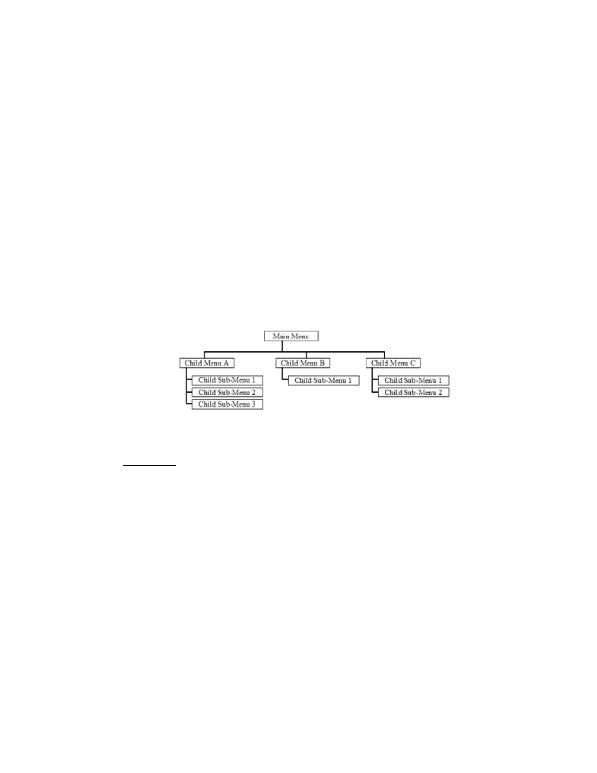
MVI71-DFNT ♦ PLC 5 Diagnostics and Troubleshooting
EtherNet/IP Client/Server Communication Module User Manual
4.2 The Configuration/Debug Menu
The Configuration and Debug menu for this module is arranged as a tree
structure, with the Main Menu at the top of the tree, and one or more sub-menus
for each menu command. The first menu you see when you connect to the
module is the Main menu.
Because this is a text-based menu system, you enter commands by typing the
command letter from your computer keyboard in Prosoft Configuration Builder
(PCB). The module does not respond to mouse movements or clicks. The
command executes as soon as you press the command letter — you do not need
to press [Enter]. When you type a command letter, a new screen will be
displayed in the Prosoft Configuration Builder (PCB) application.
4.2.1 Navigation
All of the submenus for this module contain commands to redisplay the menu or
return to the previous menu. You can always return from a submenu to the next
higher menu by pressing [M]
The organization of the menu structure is represented in simplified form in the
following illustration:
on your keyboard.
The remainder of this section shows the menus available for this module, and
briefly discusses the commands available to you.
Keystrokes
The keyboard commands on these menus are usually not case sensitive. You
can enter most commands in lowercase or uppercase letters.
The menus use a few special characters (?, -, +, @) that must be entered exactly
as shown. Some of these characters will require you to use the SHIFT,
ALT
keys to enter them correctly. For example, on US English keyboards, enter
the ?
command as SHIFT and /.
Also, take care to distinguish the different uses for uppercase letter "eye" (I),
CTRL, or
lowercase letter "el" (L), and the number one (1). Likewise, uppercase letter "oh"
(O)
and the number zero (0) are not interchangeable. Although these characters
look alike on the screen, they perform different actions on the module and may
not be used interchangeably.
ProSoft Technology, Inc. Page 51 of 175
February 3, 2011
Page 52

Diagnostics and Troubleshooting MVI71-DFNT ♦ PLC 5
User Manual EtherNet/IP Client/Server Communication Module
4.2.2 Using the Configuration/Debug Port
To connect to the module’s Configuration/Debug port:
1 Connect your computer to the module’s port using a null modem cable.
2 Start the communication program on your computer and configure the
communication parameters with the following settings:
Baud Rate 57,600
Parity None
Data Bits 8
Stop Bits 1
Software Handshaking None
3 Open the connection. When you are connected, press the [?] key on your
keyboard. If the system is set up properly, you will see a menu with the
module name followed by a list of letters and the commands associated with
them.
If there is no response from the module, follow these steps:
1 Verify that the null modem cable is connected properly between your
computer’s serial port and the module. A regular serial cable will not work.
2 Verify that RSLinx is not controlling the COM port. Refer to Disabling the
RSLinx Driver for the Com Port on the PC (page 84).
3 Verify that your communication software is using the correct settings for baud
rate, parity and handshaking.
4 On computers with more than one serial port, verify that your communication
program is connected to the same port that is connected to the module.
If you are still not able to establish a connection, you can contact ProSoft
Technology Technical Support for further assistance.
Page 52 of 175 ProSoft Technology, Inc.
February 3, 2011
Page 53

MVI71-DFNT ♦ PLC 5 Diagnostics and Troubleshooting
EtherNet/IP Client/Server Communication Module User Manual
4.2.3 Main Menu
Features available through the use of the configuration/debug port on the MVI71DFNT module are all accessed using single keystrokes on your computer. There
is a single main menu and several sub-menus presented on the port. To view the
current selections available, press the [?] key on your computer. If you are at the
main menu, the following menu appears:
If this menu is not shown, press the [M] key to display the main menu. All
facilities offered by the configuration/debugger are shown on the main menu.
Each option is discussed in the following topics.
Viewing Block Transfer Statistics
Press [B] from the Main menu to view the Block Transfer Statistics screen.
Use this command to display the configuration and statistics of the backplane
data transfer operations between the module and the processor. The information
on this screen can help determine if there are communication problems between
the processor and the module.
Tip: To determine the number of blocks transferred each second, mark the numbers displayed at a
specific time. Then some seconds later activate the command again. Subtract the previous
numbers from the current numbers and divide by the quantity of seconds passed between the two
readings.
Viewing Module Configuration
Press [C] to view the Module Configuration screen.
Use this command to display the current configuration and statistics for the
module.
Opening the Database View Menu
Press [D] to open the Database View menu.
Use this menu command to view the current contents of the module’s database.
For more information about this submenu, see Database View Menu (page 57).
Opening the Client Command Error List Menu
Press [E] to open the Client Command Error List. This list consists of multiple
pages of command list error/status data. Press [?]
to view a list of commands
available on this menu.
ProSoft Technology, Inc. Page 53 of 175
February 3, 2011
Page 54

Diagnostics and Troubleshooting MVI71-DFNT ♦ PLC 5
User Manual EtherNet/IP Client/Server Communication Module
Opening the Client Command List Menu
Press [I] to open the Client Command List menu. Use this command to view the
configured command list for the module.
Transferring the Configuration File from the PC to the Module
On the Diagnostics Menu this is referred to as Receive Module Configuration.
Press [R] to receive (download) the configuration file from your PC to the module
and store the file on the module’s Compact Flash Card (Personality Module) or
Flash RAM.
Press [Y]
to confirm the file transfer, and then follow the instructions on the
terminal screen to complete the file transfer process.
After the file has been successfully downloaded, the module will restart the
program and load the new configuration information. Review the new
configuration using menu commands [6]
configured correctly.
and [0] to verify that the module is
Transferring the Configuration File from The Module to the PC
On the Diagnostics Menu this is referred to as Send Module Configuration.
Press [S] to send (upload) the configuration file from the module to your PC.
Press [Y]
to confirm the file transfer, and then follow the instructions on the
terminal screen to complete the file transfer process.
After the file has been successfully uploaded, you can open and edit the file to
change the module’s configuration.
Resetting Diagnostic Data
Press [U] to reset the status counters for the Client and/or server(s) in the
module.
Viewing Version Information
Press [V] to view version information for the module.
Use this command to view the current version of the software for the module, as
well as other important values. You may be asked to provide this information
when calling for technical support on the product.
Values at the bottom of the display are important in determining module
operation. The Program Scan Counter value is incremented each time a
module’s program cycle is complete.
Tip: Repeat this command at one-second intervals to determine the frequency of program
execution.
Page 54 of 175 ProSoft Technology, Inc.
February 3, 2011
Page 55

MVI71-DFNT ♦ PLC 5 Diagnostics and Troubleshooting
EtherNet/IP Client/Server Communication Module User Manual
Warm Booting the Module
Press [W] from the Main menu to warm boot (restart) the module.
This command will cause the program to exit and reload, refreshing configuration
parameters that must be set on program initialization. Only use this command if
you must force the module to reboot.
Viewing Client Communication Status
Press [1] to view client communication status. Use this command to view the
statistics of the DFNT client commands sent by the MVI71-DFNT. The following
illustration shows an example of the information on this screen.
Viewing Server Status Data
Press [2], [3], [4] or [5] to view status data for the DFNT servers. The following
illustration shows an example of the status screen for the selected servers:
2 = Display servers 0 to 4
3 = Display servers 5 to 9
4 = Display servers 10 to 14
5 = Display servers 15 to 19
Note: Some implementations of the DFNT protocol support fewer DFNT servers (for example,
5201-DFNT-BACNET, which supports only five servers, rather than the twenty shown in this
illustration)
ProSoft Technology, Inc. Page 55 of 175
February 3, 2011
Page 56

Diagnostics and Troubleshooting MVI71-DFNT ♦ PLC 5
User Manual EtherNet/IP Client/Server Communication Module
Viewing DF1 Server Status Data
Press [7] to view communication status for the DF1 pass through server.
Viewing Client Configuration
Press [8] to display the configuration information for the client.
Viewing DF1 Pass-Through Server Configuration
Press [9] to view configuration information for the DF1 pass-through server.
Viewing DF1 Pass Through Port Configuration
Press [0] (zero) to view configuration information for the DF1 pass-through port.
Opening the Network Menu
Press [@] to open the Network menu.
The Network menu allows you to send, receive and view the WATTCP.CFG file
that contains the IP, gateway and other network specification information. For
more information about this submenu, see Network Menu (page 61).
Exiting the Program
Press [ESC] to restart the module and force all drivers to be loaded. The module
will use the configuration stored in the module's flash memory to configure the
module.
Page 56 of 175 ProSoft Technology, Inc.
February 3, 2011
Page 57

MVI71-DFNT ♦ PLC 5 Diagnostics and Troubleshooting
EtherNet/IP Client/Server Communication Module User Manual
4.2.4 Database View Menu
Press [D] from the Main menu to open the Database View menu. Use this menu
command to view the current contents of the module database. Press [?]
a list of commands available on this menu.
to view
Viewing Register Pages
To view sets of register pages, use the keys described below:
Command Description
[0]
[1]
[2]
Display registers 0 to 99
Display registers 1000 to 1099
Display registers 2000 to 2099
And so on. The total number of register pages available to view depends on your
module’s configuration.
Displaying the Current Page of Registers Again
Press [S] from the Database View menu to show the current page of registers
again.
This screen displays the current page of 100 registers in the database.
ProSoft Technology, Inc. Page 57 of 175
February 3, 2011
Page 58

Diagnostics and Troubleshooting MVI71-DFNT ♦ PLC 5
User Manual EtherNet/IP Client/Server Communication Module
Moving Back Through 5 Pages of Registers
Press [-] from the Database View menu to skip five pages back in the database
to see the 100 registers of data starting 500 registers before the currently
displayed page.
Moving Forward (Skipping) Through 5 Pages of Registers
Press [+] from the Database View menu to skip five pages ahead in the database
to see the 100 registers of data starting 500 registers after the currently displayed
page.
Viewing the Previous Page of Registers
Press [P] from the Database View menu to display the previous page of data.
Viewing the Next Page of Registers
Press [N] from the Database View menu to display the next page of data.
Viewing Data in Decimal Format
Press [D] from the Database View menu to display the data on the current page
in decimal format.
Viewing Data in Hexadecimal Format
Press [H] from the Database View menu to display the data on the current page
in hexadecimal format.
Viewing Data in Floating-Point Format
Press [F] from the Database View menu to display the data on the current page
in floating-point format. The program assumes that the values are aligned on
even register boundaries. If floating-point values are not aligned as such, they
are not displayed properly.
Viewing Data in ASCII (Text) Format
Press [A] from the Database View menu to display the data on the current page
in ASCII format. This is useful for regions of the database that contain ASCII
data.
Returning to the Main Menu
Press [M] to return to the Main menu.
Page 58 of 175 ProSoft Technology, Inc.
February 3, 2011
Page 59

MVI71-DFNT ♦ PLC 5 Diagnostics and Troubleshooting
EtherNet/IP Client/Server Communication Module User Manual
4.2.5 Master Command Error List Menu
Use this menu to view the command error list for the module. Press [?] to view a
list of commands available on this menu.
Redisplaying the Current Page
Press [S] to display the current page of data.
Moving Back Through 5 Pages of Commands
Press [-] to display data for last 5 page commands.
Viewing the Previous Page of Commands
Press [P] to display the previous page of commands.
Moving Forward (Skipping) Through 5 Pages of Commands
Press [+] to display data for the next page of commands.
Viewing the Next Page of Commands
Press [N] to display the next page of commands.
Returning to the Main Menu
Press [M] to return to the Main menu.
ProSoft Technology, Inc. Page 59 of 175
February 3, 2011
Page 60

Diagnostics and Troubleshooting MVI71-DFNT ♦ PLC 5
User Manual EtherNet/IP Client/Server Communication Module
4.2.6 Master Command List Menu
Use this menu to view the command list for the module. Press [?] to view a list of
commands available on this menu.
Redisplaying the Current Page
Press [S] to display the current page of data.
Viewing the Previous 50 Commands
Press [-] to view the previous 50 commands.
Viewing the Previous Page of Commands
Press [P] to display the previous page of commands.
Viewing the Next 50 Commands
Press [+] to view the next 50 commands from the master command list.
Viewing the Next Page of Commands
Press [N] to display the next page of commands.
Returning to the Main Menu
Press [M] to return to the Main menu.
Page 60 of 175 ProSoft Technology, Inc.
February 3, 2011
Page 61

MVI71-DFNT ♦ PLC 5 Diagnostics and Troubleshooting
EtherNet/IP Client/Server Communication Module User Manual
4.2.7 Network Menu
From the main menu press [@] to display the Network menu screen. The
Network menu allows you to send, receive, and view the WATTCP.CFG file that
contains the IP and module addresses, and other network information.
Transferring WATTCP.CFG to the Module
Press [R] to transfer a new WATTCP.CFG file from the PC to the module. Use
this command to change the network configuration for the module (for example,
the module’s IP address).
Press [Y] to confirm the file transfer, and then follow the instructions on the
terminal screen to complete the file transfer process.
Transferring WATTCP.CFG to the PC
Press [S] to transfer the WATTCP.CFG file from the module to your PC.
Press [Y] to confirm the file transfer, and then follow the instructions on the
terminal screen to complete the file transfer process.
After the file has been successfully transferred, you can open and edit the file to
change the module’s network configuration.
ProSoft Technology, Inc. Page 61 of 175
February 3, 2011
Page 62

Diagnostics and Troubleshooting MVI71-DFNT ♦ PLC 5
User Manual EtherNet/IP Client/Server Communication Module
Viewing the WATTCP.CFG File on the module
Press [V] to view the module’s WATTCP.CFG file. Use this command to confirm
the module’s current network settings.
Returning to the Main Menu
Press [M] to return to the Main menu.
Page 62 of 175 ProSoft Technology, Inc.
February 3, 2011
Page 63

MVI71-DFNT ♦ PLC 5 Diagnostics and Troubleshooting
EtherNet/IP Client/Server Communication Module User Manual
4.3 Reading Status Data from the Module
The MVI71-DFNT module returns two status data blocks that can be used to
determine the module’s operating status. This data is requested by the ladder
logic and returned in the module’s M1 file. This data can also be viewed using
the Configuration/Debug port with Prosoft Configuration Builder (PCB). The
Configuration/Debug port provides the following functionality:
Full view of the module’s configuration data
View of the module’s status data
Complete display of the module’s internal database (registers 0 to 3999)
Version Information
Control over the module (warm boot, cold boot)
Facility to upload and download the module’s configuration file
ProSoft Technology, Inc. Page 63 of 175
February 3, 2011
Page 64

Diagnostics and Troubleshooting MVI71-DFNT ♦ PLC 5
User Manual EtherNet/IP Client/Server Communication Module
Page 64 of 175 ProSoft Technology, Inc.
February 3, 2011
Page 65

MVI71-DFNT ♦ PLC 5 Reference
EtherNet/IP Client/Server Communication Module User Manual
5 Reference
In This Chapter
Product Specifications
Functional Overview .............................................................................. 69
Cable Connections ................................................................................ 82
Pass-Through Ports .............................................................................. 87
MVI71-DFNT Status Data Definition ...................................................... 88
Error Codes ......................................................................................... 104
TCP/IP Interface Errors ....................................................................... 108
Configuration Data .............................................................................. 110
DFNT Command Entry Form ............................................................... 113
Command Function Codes .................................................................. 114
General Command Structure ............................................................... 115
PLC-5 Processor Specifics .................................................................. 129
SLC Processor Specifics ..................................................................... 131
MicroLogix Processor Specifics ........................................................... 132
ControlLogix Processor Specifics ........................................................ 133
Server Driver ....................................................................................... 134
Accessing a PLC Processor via Ethernet Using MVI71-DFNT ............ 159
........................................................................... 66
ProSoft Technology, Inc. Page 65 of 175
February 3, 2011
Page 66

Reference MVI71-DFNT ♦ PLC 5
User Manual EtherNet/IP Client/Server Communication Module
5.1 Product Specifications
5.1.1 EtherNet/IP (Explicit Messaging) Compatible Devices
List of Rockwell Automation material that support EPIC:
PLC5/E rev C/N, D/E, E/D
SLC5/05 series A, OS503 frn4
1785-ENET Series A, rev D
Interchange V6.2
MicroLogix 1100/1400/ANY via 1761-NET-ENI
CompactLogix 1768-L43/L45 via 1768-ENBT
CompactLogix 1769-L32E/L35E/ANY via 1761-NET-ENI
CompactLogix L23E
RSLinx Gateway V1.7+
ControlLogix 1756-ENET/ENBT/EN2T
5.1.2 General Specifications
Single Slot - 1771 backplane compatible
The module is recognized as an Input/Output module and has access to
processor memory for data transfer between processor and module
Ladder Logic is used for data transfer between module and processor.
Sample ladder file included.
Configuration data obtained from configuration text file downloaded to
module. Sample configuration file included.
Page 66 of 175 ProSoft Technology, Inc.
February 3, 2011
Page 67

MVI71-DFNT ♦ PLC 5 Reference
EtherNet/IP Client/Server Communication Module User Manual
5.1.3 Hardware Specifications
Specification Description
Form Factor Single Slot 1771 chassis compatible
BTR/BTW data transfer
Local or remote rack
Backplane current load 800 mA @ 5 V
Operating temperature 0 to 60°C (32 to 140°F)
Storage temperature -40 to 85°C (-40 to 185°F)
Shock 30g operational
50g non-operational
Vibration 5 g from 10150 Hz
Relative humidity 5% to 95% (non-condensing)
LED Indicators Module status
Backplane transfer status
Application status
Serial activity and error LED status
Configuration Serial port (CFG) DB-9M PC compatible
RS-232
Hardware handshaking
Ethernet Port (Ethernet
modules)
RJ45 Connector
Link and activity LED indicators
Electrical Isolation 1500 V rms at 50 Hz to 60 Hz
for 60 s, applied as specified in section 5.3.2 of IEC
60950: 1991
Ethernet Broadcast Storm Resiliency = less than or
equal to 5000 [ARP] frames-per-second and less
than or equal to 5 minutes duration
ProSoft Technology, Inc. Page 67 of 175
February 3, 2011
Page 68

Reference MVI71-DFNT ♦ PLC 5
User Manual EtherNet/IP Client/Server Communication Module
5.1.4 Functional Specifications
PLC processor in-chassis EtherNet/IP bridge to optimize data throughput
while communicating with HMI or SCADA and other control platforms without
losing valuable process control bandwidth
Support of up to 4000 PLC registers user data files
User-definable module memory usage
10/100 Base-T Ethernet compatible interface
Functions as a server or a client
Configurable parameters for the client include:
o A minimum response delay of 0 to 65535 milliseconds
o A response timeout of 1 to 65535 milliseconds
o A retry count of 0 to 20
Status data available in ladder logic
Support for PLC processor programming over Ethernet using a TCP/IP service
and a serial port on the module connected to channel 0 of the processor. The
module’s third port emulates Channel 0 of the processor to pass through
messages from the port to the processor
Server Specifications
Supports EtherNet/IP explicit, connected, and unconnected class messaging
Twenty independent server connections permit remote clients to interact with
all data contained in the module
Data can be derived from other clients on the network, through the client on
the module, or from the PLC processor
Client Specifications
Actively issues connected, explicit messages to other nodes on the network
Supports 100 user-defined commands from a single client
Allows command control from ladder logic
Pass-through services
Permits remote programming of the PLC processor on the Ethernet network
via a pass-through
TCP/IP service and a serial communication port (pass-through port) on the
module
The third port on the module can emulate the Channel 0 port on the PLC,
This allows a DF1 master device attached to the emulated (Channel 0) port to
monitor and control data in the PLC
Page 68 of 175 ProSoft Technology, Inc.
February 3, 2011
Page 69

MVI71-DFNT ♦ PLC 5 Reference
EtherNet/IP Client/Server Communication Module User Manual
5.2 Functional Overview
5.2.1 General Concepts
The following discussion explains several concepts that are important for
understanding module operation.
Module Power Up
On power up the module begins performing the following logical functions:
1 Initialize hardware components
2 Initialize PLC backplane driver
o Test and clear all RAM
o Initialize the serial communication ports
o Read configuration for module from DFNT.CFG file on Compact Flash
Disk
3 Initialize Module Register space
4 Enable Server Drivers
5 Enable Client Driver
6 Initialize all serial communication ports
After the module receives the configuration, the module begins communicating
with other nodes on the network, depending on the configuration.
Main Logic Loop
Upon completing the power-up configuration process, the module enters an
infinite loop that performs the functions shown in the following diagram.
ProSoft Technology, Inc. Page 69 of 175
February 3, 2011
Page 70

Reference MVI71-DFNT ♦ PLC 5
User Manual EtherNet/IP Client/Server Communication Module
Block Transfer Backplane Data Transfer
The MVI71-DFNT module communicates directly over the PLC backplane. Data
is paged between the module and the PLC processor across the backplane using
BTR and BTW operations. Data is transferred from the module to the processor
using the BTR blocks, and data is transferred from the processor to the module
using BTW blocks.
The following illustration shows the data transfer method used to move data
between the PLC processor, the MVI71-DFNT module, and the Ethernet
Network.
As shown in the diagram, all data transferred between the module and the
processor over the backplane is through the BTR and BTW blocks. Ladder logic
must be written in the PLC processor to interface the block data with the
module's internal database. All data used by the module is stored in its internal
database. The following illustration shows the layout of the database:
Module’s Internal Database Structure
4000 registers for user data
Register Data
0
3999
Page 70 of 175 ProSoft Technology, Inc.
February 3, 2011
Page 71

MVI71-DFNT ♦ PLC 5 Reference
EtherNet/IP Client/Server Communication Module User Manual
5.2.2 Normal Data Transfer
Normal data transfer includes the transferring of data between the MVI71-DFNT
database and the PLC data files. These data are transferred through read (BTR)
and write (BTW) blocks. Refer to the Module Configuration section for a
description of the ladder logic required to perform the data movement within the
PLC processor. The structure and function of each block is discussed in the
following topics.
Read Block
These blocks of data transfer information from the module to the PLC processor.
When data is received on one of the servers, a data block is built. The structure
of this block type is shown in the following table.
Word Offset Description
0 Read Block ID
1 Next Write Block ID
2 to 63 Read Data
Write Block
These blocks of data transfer information from the PLC processor to the module.
The structure of the BTW block is shown in the following table.
Word Offset Description
0 Write Block ID (copied from the previous Read block)
1 to 63 Write Data
The following shows the valid block IDs for normal transfer:
Block ID Definition
-1 and 0 Null blocks that do not contain any data.
1 to 67 Data read and write blocks to transfer data for the module’s database
between the processor and the module.
How Data is Transferred
In order to understand how the data is transferred between the processor and the
module, you must understand the Read Data and Write Data area concept in the
module’s database. The module’s database can be partially, or totally divided
into Read Data Areas and Write Data Areas.
These areas are defined by the user when the configuration file is being edited.
The following parameters define the Read and Write data areas:
Read Register Start = 0
Read Register Count = 120
Write Register Start = 200
Write Register Count = 120
Each area is broken down into blocks of 60 words. Therefore, the Read Register
Count and Write Register Count parameters should be multiples of 60.
ProSoft Technology, Inc. Page 71 of 175
February 3, 2011
Page 72

Reference MVI71-DFNT ♦ PLC 5
User Manual EtherNet/IP Client/Server Communication Module
The Read Data Area will be transferred from the module to the PLC processor.
The Write Data Area will be transferred from the PLC processor to the module.
The following example shows the resulting data flow:
5.2.3 Module Control Blocks
Specific write block IDs are reserved for module control operations. These blocks
request that the module perform specific tasks. The following write blocks are
valid for module control.
Block ID Definition
250 and 251 Status data request and response blocks
1000 to 1066 Blocks used to initialize the module’s database with values in the processor on
startup.
2000 Request and respond with command list error data for a set of commands.
3000 Set the enable code for a set of commands to 0 to disable polling.
3001 Set the enable code for a set of commands to 1 to enable polling.
3002 Set the enable code for a set of commands to 2 to enable conditional polling.
9998 Request block to warm boot the module
9999 Request block to cold boot the module
Page 72 of 175 ProSoft Technology, Inc.
February 3, 2011
Page 73

MVI71-DFNT ♦ PLC 5 Reference
EtherNet/IP Client/Server Communication Module User Manual
Status Data Request Block (250 to 254)
In order to read the module’s general error and status data to the PLC, it must
make a special request using the status data request block. The following tables
lists the values recognized by the module:
Offset Description
250 Module and pass-through port end server status
251 Status for servers 0 to 4
252 Status for servers 5 to 9
253 Status for servers 10 to 14
254 Status for servers 15 to 19
MVI71-DFNT Status Data Definition contains a complete listing of the data
returned for the status blocks.
Initialize Output Data Blocks (1000 to 1066)
When the module performs a restart operation, it requests output data from the
processor to initialize the module’s read data area. Use the Initialize Output
Data parameter in the configuration file to bring the module to a known state after
a restart operation. The structure of the block used to request the data is shown
in the following table.
Block Request
Offset Description Length
0 1000 to 1066 1
1 1000 to 1066 1
2 to 63 Not used 62
The command control value of 1000 is moved as the Block Transfer Write ID to
indicate that the module is requesting initialization of the Read Data area. Ladder
logic in the processor must recognize this command and place the correct
information in the database. The format of the returned write block is shown in
the following table.
Block Response
Offset Description Length
0 1000 to 1066 1
1 to 60 Data to place in database 60
61 to 63 Not used 3
For example, for a Read Data Area of 2 blocks (120 words), blocks 1000 and
1001 would be used.
Command Error List Request Block (2000)
This command control request (control code of 2000) requests the command list
error data set. The error codes returned in the block are DFNT error codes noted
in the Reference chapter. The format of the request block from the ladder logic
has the following format:
ProSoft Technology, Inc. Page 73 of 175
February 3, 2011
Page 74

Reference MVI71-DFNT ♦ PLC 5
User Manual EtherNet/IP Client/Server Communication Module
Block Request
Offset Description Length
0 2000 1
1 Command start index 1
2 Command count 1
3 to 63 Not used 61
After the module processes the block, it supplies the following values in the
control register area:
Block Response
Offset Description Length
0 2000 1
1 Block write ID 1
2 Command start index 1
3 Number of errors in list 1
4 to 63 Command error list returned 60
Command Control Blocks (3000 to 3002)
Blocks 3000 to 3002 alter the command type field for a set of commands in the
client command lists. Block 3000 disables commands by setting the enable type
field to value of 0. Block 3001 enables commands by setting the enable type field
to a value of 1. The commands will be issued at the time interval no more
frequent than set in the poll interval parameter for the command. Block 3002 sets
the enable type field to a value of 2. This operation should only be used for write
functions as the command is only executed when the data referenced by the
command changes. The general format for the blocks is as follows:
Block Request
Offset Description Length
0 3000 to 3002 1
1 Command count 1
2 to 63 List of command indices on which to perform the operation. 62
After the module processes the block, it supplies the following values in the
control register area:
Block Response
Offset Description Length
0 3000 to 3002 1
1 Block write ID 1
2 Number of commands processed 1
3 to 63 Not used 61
Page 74 of 175 ProSoft Technology, Inc.
February 3, 2011
Page 75

MVI71-DFNT ♦ PLC 5 Reference
EtherNet/IP Client/Server Communication Module User Manual
Warm Boot Block (9998)
This block is sent from the PLC processor to the module when the module is
required to perform a warm-boot (software reset) operation. This block is
commonly sent to the module any time configuration data modifications are made
in the controller tags data area. This causes the module to read the new
configuration information and to restart. The following table describes the format
of the control block.
Block Request
Offset Description Length
0 9998 1
1 to 63 Not used 63
Cold Boot Block (9999)
This block is sent from the PLC processor to the module when the module is
required to perform the cold boot (hardware reset) operation. This block is sent to
the module when a hardware problem is detected by the ladder logic that
requires a hardware reset. The following table describes the format of the control
block.
Block Request
Offset Description Length
0 9999 1
1 to 63 Not used 63
ProSoft Technology, Inc. Page 75 of 175
February 3, 2011
Page 76

Reference MVI71-DFNT ♦ PLC 5
the internal database in the module. If the command is a read command, the data is read
User Manual EtherNet/IP Client/Server Communication Module
5.2.4 Data Flow between MVI71-DFNT Module and PLC Processor
The following discussion outlines the flow of data between the two pieces of
hardware (PLC processor and MVI71-DFNT module) and other nodes on the
TCP/IP network under the module’s different operating modes. The module
contains both servers and a Client.
The following topics discuss the operation of the server and Client drivers.
Server Driver
The Server Driver allows the MVI71-DFNT module to respond to data read and
write commands issued by clients on the Ethernet/IP network using explicit
messaging. The following flow chart and associated table describe the flow of
data into and out of the module.
Step Description
1 The server driver receives the configuration information from the configuration file on the
Compact Flash Disk, and the module initializes the servers.
2 A Host device, such as a ControlLogix processor, RSLinx or an HMI application issues a
read or write command to the module. The server driver qualifies the message before
accepting it into the module.
3 After the module accepts the command, the data is immediately transferred to or from
out of the database and a response message is built. If the command is a write
command, the data is written directly into the database and a response message is built.
4 After the data processing has been completed in Step 3, the response is issued to the
originating master node.
5 Status data for the servers is passed to the processor under ladder logic control using
the command control data area in the M1 file.
Page 76 of 175 ProSoft Technology, Inc.
February 3, 2011
Page 77

MVI71-DFNT ♦ PLC 5 Reference
EtherNet/IP Client/Server Communication Module User Manual
The DFNT module supports server functionality using the reserved ControlNet
service port 0xAF12. Services supported in the module permit client applications
(that is, RSView, ControlLogix processors and RSLinx) to read from and write to
the module’s database. This document discusses the requirements for attaching
to the module using several client applications.
The following illustration shows the relationship of the DFNT module’s
functionality to devices on an Ethernet network:
Server functionality places all data transfer operations outside the module. There
is no configuration required in the module other than setting up the network and
database parameters in the configuration file. Ladder logic in attached
processors use MSG instructions to perform read and write operations on the
module’s internal database.
When RSLinx links a user application to the module, the module’s server
functionality must be used. RSLinx exists on an Ethernet network only as a client
application. It cannot act as a server. User applications can use the DDE/OPC
capabilities built into RSLinx to interface with the data in the DFNT module.
RSView can link directly to the module using drivers supplied by RSLinx.
ProSoft Technology, Inc. Page 77 of 175
February 3, 2011
Page 78

Reference MVI71-DFNT ♦ PLC 5
User Manual EtherNet/IP Client/Server Communication Module
The internal database of the DFNT module is used as the source (read requests)
and destination (write requests) for requests from remote clients. Access to the
database depends on the MSG command type executed to interface with the
database. The following table defines the relationship of the module’s internal
database to the addresses required in the MSG instructions:
MSG Instruction Type
Database Address PLC2 PLC5 or SLC ControlLogix
PCCC CIP Integer
0 0 N10:0 N10:0 Int_data[0]
999 999 N19:99 N19:99 Int_data[999]
1000 1000 N20:0 N20:0 Int_data[1000]
1999 1999 N29:99 N29:99 Int_data[1999]
2000 2000 N30:0 N30:0 Int_data[2000]
2999 2999 N39:99 N39:99 Int_data[2999]
3000 3000 N40:0 N40:0 Int_data[3000]
3999 4000 N49:99 N49:99 Int_data[3999]
MSG Instruction Type
Database
Address
0 BoolData[0] BitAData[0] SIntData[0] DIntData[0] RealData[0]
999 BoolData[15984] SIntData[1998]
1000 BoolData[16000] BitAData[500] SIntData[2000] DIntData[500] RealData[500]
1999 BoolData[31984] SIntData[3998]
2000 BoolData[32000] BitAData[1000] SIntData[4000] DIntData[1000] RealData[1000]
2999 BoolData[47984] SIntData[5998]
3000 BoolData[48000] BitAData[1500] SIntData[6000] DIntData[1500] RealData[1500]
3999 BoolData[63999] SIntData[9998]
CIP Boolean ControlLogix
CIP Bit Array CIP Byte CIP Double
CIP Real
Int
Page 78 of 175 ProSoft Technology, Inc.
February 3, 2011
Page 79

MVI71-DFNT ♦ PLC 5 Reference
EtherNet/IP Client/Server Communication Module User Manual
When using PLC5 or SLC commands, access to the database is through
simulated "N" files. For example, to access database element 3012, use the file
address of N40:12. When using CIP Data Table Read or Write commands, use
the various data[ ] tag arrays described in the following table. For example, use
int_data[3012] to access database register 3012 as an integer value.
Data Type Tag Name Length of Each Element in
CIP message
BOOL BOOLData[ ] 1 0 to 63999
Bit Array BITAData[ ] 4 0 to 1999
SINT SINTData[ ] 1 0 to 7999
INT INT_Data[ ] 2 0 to 3999
DINT DINTData[ ] 4 0 to 1999
REAL REALData[ ] 4 0 to 1999
Array Range for 4000
Element Database
Before attempting to use the module on a network, verify that the DFNT module
is correctly configured and connected to the network. A network program such as
PING can be utilized to make certain the module can be seen on the network.
Use ProSoft Configuration Builder to verify correct operation, and to transfer
configuration files to and from the module.
The following table shows the supported commands when the module acts as a
slave (server):
Basic Command Set Functions
Command Function Definition Supported in Slave
0x00 N/A Protected Write X
0x01 N/A Unprotected Read X
0x02 N/A Protected Bit Write X
0x05 N/A Unprotected Bit Write X
0x08 N/A Unprotected Write X
PLC-5 Command Set Functions
Command Function Definition Supported in Slave
0x0F 0x00 Word Range Write (Binary Address) X
0x0F 0x01 Word Range Read (Binary Address) X
0x0F Typed Range Read (Binary Address) X
0x0F Typed Range Write (Binary Address) X
0x0F 0x26 Read-Modify-Write (Binary Address)
0x0F 0x00 Word Range Write (ASCII Address) X
0x0F 0x01 Word Range Read (ASCII Address) X
0x0F 0x26 Read-Modify-Write (ASCII Address)
ProSoft Technology, Inc. Page 79 of 175
February 3, 2011
Page 80

Reference MVI71-DFNT ♦ PLC 5
User Manual EtherNet/IP Client/Server Communication Module
SLC-500 Command Set Functions
Command Function Definition Supported in Slave
0x0F 0xA1 Protected Typed Logical Read With Two Address
Fields
0x0F 0XA2 Protected Typed Logical Read With Three Address
Fields
0x0F 0XA9 Protected Typed Logical Write With Two Address
Fields
0x0F 0XAA Protected Typed Logical Write With Three Address
Fields
0x0F 0XAB Protected Typed Logical Write With Mask (Three
Address Fields)
X
X
X
X
Client Driver
In the client driver, the MVI71-DFNT module is responsible for issuing read or
write commands to servers on the Ethernet/IP network using explicit, connected
messaging. These commands are user configured in the module via the Client
Command List received from the module's configuration file (DFNT.CFG).
Command status is returned to the processor for each individual command in the
command list status block in the command control data area. Ladder logic is
responsible for acquiring this data from the module. The following flow chart and
associated table show the flow of data into and out of the module.
Page 80 of 175 ProSoft Technology, Inc.
February 3, 2011
Page 81

MVI71-DFNT ♦ PLC 5 Reference
EtherNet/IP Client/Server Communication Module User Manual
Step Description
1 The client driver obtains configuration data from the DFNT.CFG file when the module
restarts. The configuration data obtained includes the timeout parameters and the
Command List. These values are used by the driver to determine the type of commands
to be issued to the other nodes on the Ethernet/IP (see Module Configuration).
2 After configuration, the client driver begins transmitting read and/or write commands to
the other nodes on the network. If writing data to another node, the data for the write
command is obtained from the module's internal database to build the command.
3 Presuming successful processing by the node specified in the command, a response
message is received into the client driver for processing.
4 Data received from the node on the network is passed into the module's internal
database, assuming a read command.
5 Status data is returned to the PLC processor for the client and a Command List error
table can be established in the module's internal database. This data is requested using
the command control data area and is a responsibility of the ladder logic.
The Module Setup section provides a complete description of the parameters
required to define the client.
Client Command List
In order for the client to function, the module's Client Command List must be
defined. This list contains up to 100 individual entries, with each entry containing
the information required to construct a valid command. This includes the
following:
Command enable mode ((0) disabled, (1) continuous or (2) conditional)
IP address of the remote server
Slot number for processor when interfacing with a ControlLogix processor
Command Type - Read or Write command
Database Address - Determines where data will be placed and/or obtained
Address information to access data in remote unit
Count - Select the number of words to be transferred
Poll Delay - (1/10
th
seconds)
ProSoft Technology, Inc. Page 81 of 175
February 3, 2011
Page 82

Reference MVI71-DFNT ♦ PLC 5
User Manual EtherNet/IP Client/Server Communication Module
5.3 Cable Connections
The MVI71-DFNT module has the following functional communication
connections installed:
One Ethernet port (RJ45 connector)
One RS-232 Configuration/Debug port (RJ45 connector)
5.3.1 Ethernet Connection
The MVI71-DFNT module has an RJ45 port located on the front of the module,
labeled Ethernet, for use with the TCP/IP network. The module is connected to
the Ethernet network using an Ethernet cable between the module’s Ethernet
port and an Ethernet switch or hub.
Note: Depending on hardware configuration, you may see more than one RJ45 port on the
module. The Ethernet port is labeled Ethernet.
Warning: The MVI71-DFNT module is NOT compatible with Power Over Ethernet (IEEE802.3af /
IEEE802.3at) networks. Do NOT connect the module to Ethernet devices, hubs, switches or
networks that supply AC or DC power over the Ethernet cable. Failure to observe this precaution
may result in damage to hardware, or injury to personnel.
Important: The module requires a static (fixed) IP address that is not shared with any other device
on the Ethernet network. Obtain a list of suitable IP addresses from your network administrator
BEFORE configuring the Ethernet port on this module.
Page 82 of 175 ProSoft Technology, Inc.
February 3, 2011
Page 83

MVI71-DFNT ♦ PLC 5 Reference
EtherNet/IP Client/Server Communication Module User Manual
Ethernet Port Configuration - wattcp.cfg
The wattcp.cfg file must be set up properly in order to use a TCP/IP network
connection. You can view the current network configuration in ProSoft
Configuration Builder (PCB), as shown:
You may also view the network configuration using a PC serial port connection
and an ASCII terminal program (like Windows HyperTerminal) by selecting [@]
(Network Menu) and [V] (View) options when connected to the Debug port. For
more information on serial port access, see the chapter on Diagnostics and
Troubleshooting (page 45).
ProSoft Technology, Inc. Page 83 of 175
February 3, 2011
Page 84

Reference MVI71-DFNT ♦ PLC 5
User Manual EtherNet/IP Client/Server Communication Module
5.3.2 RS-232 Configuration/Debug Port
This port is physically an RJ45 connection. An RJ45 to DB-9 adapter cable is
included with the module. This port permits a PC based terminal emulation
program to view configuration and status data in the module and to control the
module. The cable for communications on this port is shown in the following
diagram:
Disabling the RSLinx Driver for the Com Port on the PC
The communication port driver in RSLinx can occasionally prevent other
applications from using the PC’s COM port. If you are not able to connect to the
module’s configuration/debug port using ProSoft Configuration Builder (PCB),
HyperTerminal or another terminal emulator, follow these steps to disable the
RSLinx driver.
1 Open RSLinx and go to COMMUNICATIONS > RSWHO.
2 Make sure that you are not actively browsing using the driver that you wish to
stop. The following shows an actively browsed network.
3 Notice how the DF1 driver is opened, and the driver is looking for a processor
on node 1. If the network is being browsed, then you will not be able to stop
this driver. To stop the driver your RSWho screen should look like this:
Page 84 of 175 ProSoft Technology, Inc.
February 3, 2011
Page 85
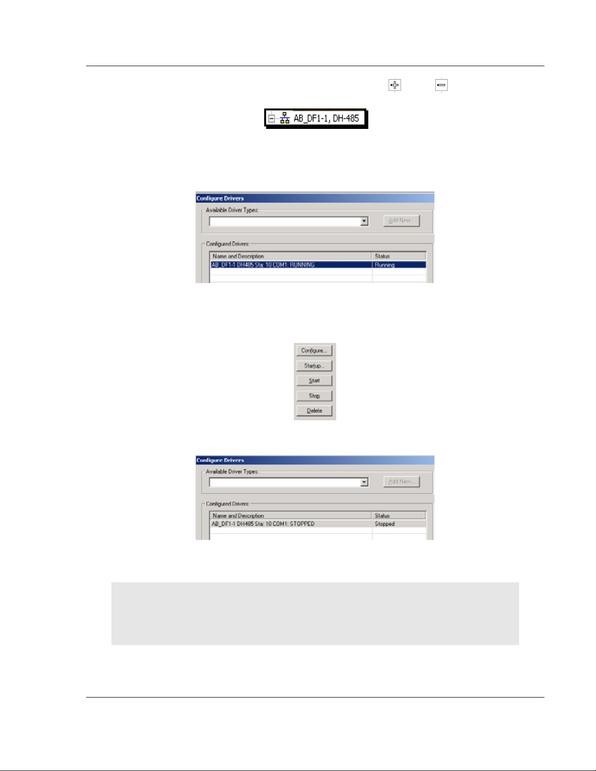
MVI71-DFNT ♦ PLC 5 Reference
EtherNet/IP Client/Server Communication Module User Manual
Branches are displayed or hidden by clicking on the or the icons.
4 When you have verified that the driver is not being browsed, go to
C
OMMUNICATIONS > CONFIGURE DRIVERS.
You may see something like this:
If you see the status as running, you will not be able to use this com port for
anything other than communication to the processor. To stop the driver press
the S
TOP button on the side of the window:
5 After you have stopped the driver you will see the following.
6 You may now use the com port to connect to the debug port of the module.
Note: You may need to shut down and restart your PC before it will allow you to stop the driver
(usually only on Windows NT machines). If you have followed all of the above steps, and it will not
stop the driver, then make sure you do not have RSLogix open. If RSLogix is not open, and you
still cannot stop the driver, then reboot your PC.
ProSoft Technology, Inc. Page 85 of 175
February 3, 2011
Page 86

Reference MVI71-DFNT ♦ PLC 5
User Manual EtherNet/IP Client/Server Communication Module
5.3.3 DB9 to RJ45 Adaptor (Cable 14)
Page 86 of 175 ProSoft Technology, Inc.
February 3, 2011
Page 87

MVI71-DFNT ♦ PLC 5 Reference
EtherNet/IP Client/Server Communication Module User Manual
5.4 Pass-Through Ports
Two pass-through ports are provided on the module. Port 2 can be connected to
the processor’s Channel 0 port and Port 3 can be connected to a remote DF1
master device. The cable configuration used on the ports depends on the RSinterface selected for the port using the jumpers located on the MVI circuit board.
The following are port pin-outs for several configurations of the ports:
ProSoft Technology, Inc. Page 87 of 175
February 3, 2011
Page 88

Reference MVI71-DFNT ♦ PLC 5
User Manual EtherNet/IP Client/Server Communication Module
5.5 MVI71-DFNT Status Data Definition
This section contains a description of the members present in the status data
blocks returned to the PLC processor under ladder logic control. The five blocks,
250, 251, 252, 253, and 254, are requested and returned in the module’s M1 file
in the command control data area under ladder logic control.
The data set returned to the processor in the M1 file for a 250 request has the
following definition:
5.5.1 BTR Response Block (250)
Offset Content Description
0 Block read ID This word contains the value of 250 to indicate this
specific status block
1 Block Write ID This word contains the next write block to receive
from the processor.
2 Program Scan Count This value is incremented each time a complete
program cycle occurs in the module.
3 to 4 Product Product Name (ASCII)
5 to 6 Rev Revision (ASCII)
7 to 8 Op Sys Operating System (ASCII)
9 to 10 Run Production Run Number (ASCII)
Reserved
Offset Content Description
11 Not Used Reserved
12 Not Used Reserved
13 Not Used Reserved
14 Not Used Reserved
15 Not Used Reserved
16 Not Used Reserved
17 Not Used Reserved
18 Not Used Reserved
19 Not Used Reserved
20 Not Used Reserved
Page 88 of 175 ProSoft Technology, Inc.
February 3, 2011
Page 89

MVI71-DFNT ♦ PLC 5 Reference
EtherNet/IP Client/Server Communication Module User Manual
Client 0 Status
Offset Content Description
21 Client Cmd Request This value is incremented each time a command
request is issued.
22 Client Cmd Response This value is incremented each time a command
response is received.
23 Client Cmd Error This value is incremented each time an error
message is received from a remote unit or a local
error is generated for a command.
24 Client Request Count This value is incremented each time a request
message is issued.
25 Client Response Count This value is incremented each time a response
message is received.
26 Client Error Sent Count This value is incremented each time an error is sent
from the client.
27 Client Error Received
Count
This value is incremented each time an error is
received from a remote unit.
28 Client Cfg Error Word This word contains a bit map that defines
configuration errors in the configuration file for the
client.
29 Client Current Error Code This value corresponds to the current error code for
the client.
30 Client Last Error Code This value corresponds to the last error code
recorded for the client.
Block Status
Offset Content Description
31 Read Block Count This field contains the total number of read blocks
transferred from the module to the processor.
32 Write Block Count This field contains the total number of write blocks
transferred from the processor to the module.
33 Parse Block Count This field contains the total number of blocks
successfully parsed that were received from the
processor.
34 Command Event Block
Count
This field contains the total number of command
event blocks received from the processor.
35 Command Block Count This field contains the total number of command
blocks received from the processor.
36 Error Block Count This field contains the total number of block errors
recognized by the module.
ProSoft Technology, Inc. Page 89 of 175
February 3, 2011
Page 90

Reference MVI71-DFNT ♦ PLC 5
User Manual EtherNet/IP Client/Server Communication Module
Pass-Through Server Status
Offset Content Description
37 Socket State
38 Connection State
39 Open Count Total number of times the server has performed an
open operation.
40 Establish Count Total number of times a connection has been
established on the server.
41 Close Count Total number of times the server has performed a
close operation.
42 Read Total number of packets received by the server.
43 Message Total number of message receive by the server.
44 Write Total number of packets sent from the server to the
client.
45 Timeout Total number of times the server as reached a
connection timeout condition.
46 Host Port Service port on client connected to the server.
47 to 48 Host IP Address IP address of the client connected to the server.
49 PTP Cfg Error Word Pass-through port configuration error word.
50 PTS Cfg Error Word Pass-through server configuration error word.
5.5.2 BTR Response Block (251)
Offset Content Description
0 Block read ID This word contains the value of 251 to indicate this
specific status block
1 Block Write ID This word contains the next write block to receive
from the processor.
Page 90 of 175 ProSoft Technology, Inc.
February 3, 2011
Page 91

MVI71-DFNT ♦ PLC 5 Reference
EtherNet/IP Client/Server Communication Module User Manual
Server 0 Status
Offset Content Description
2 Socket State
3 Connection State
4 Open Count Total number of times the server has performed an
open operation.
5 Establish Count Total number of times a connection has been
established on the server.
6 Close Count Total number of times the server has performed a
close operation.
7 Read Total number of packets received by the server.
8 Message Total number of message receive by the server.
9 Write Total number of packets sent from the server to the
client.
10 Timeout Total number of times the server as reached a
connection timeout condition.
11 Host Port Service port on client connected to the server.
12 to 13 Host IP Address IP address of the client connected to the server.
Server 1 Status
Offset Content Description
14 Socket State
15 Connection State
16 Open Count Total number of times the server has performed an
open operation.
17 Establish Count Total number of times a connection has been
established on the server.
18 Close Count Total number of times the server has performed a
close operation.
19 Read Total number of packets received by the server.
20 Message Total number of message receive by the server.
21 Write Total number of packets sent from the server to the
client.
22 Timeout Total number of times the server as reached a
connection timeout condition.
23 Host Port Service port on client connected to the server.
24 to 25 Host IP Address IP address of the client connected to the server.
ProSoft Technology, Inc. Page 91 of 175
February 3, 2011
Page 92

Reference MVI71-DFNT ♦ PLC 5
User Manual EtherNet/IP Client/Server Communication Module
Server 2 Status
Offset Content Description
26 Socket State
27 Connection State
28 Open Count Total number of times the server has performed an
open operation.
29 Establish Count Total number of times a connection has been
established on the server.
30 Close Count Total number of times the server has performed a
close operation.
31 Read Total number of packets received by the server.
32 Message Total number of message receive by the server.
33 Write Total number of packets sent from the server to the
client.
34 Timeout Total number of times the server as reached a
connection timeout condition.
35 Host Port Service port on client connected to the server.
36 to 37 Host IP Address IP address of the client connected to the server.
Server 3 Status
Offset Content Description
38 Socket State
39 Connection State
40 Open Count Total number of times the server has performed an
open operation.
41 Establish Count Total number of times a connection has been
established on the server.
42 Close Count Total number of times the server has performed a
close operation.
43 Read Total number of packets received by the server.
44 Message Total number of message receive by the server.
45 Write Total number of packets sent from the server to the
client.
46 Timeout Total number of times the server as reached a
connection timeout condition.
47 Host Port Service port on client connected to the server.
48 to 49 Host IP Address IP address of the client connected to the server.
Page 92 of 175 ProSoft Technology, Inc.
February 3, 2011
Page 93

MVI71-DFNT ♦ PLC 5 Reference
EtherNet/IP Client/Server Communication Module User Manual
Server 4 Status
Offset Content Description
50 Socket State
51 Connection State
52 Open Count Total number of times the server has performed an
open operation.
53 Establish Count Total number of times a connection has been
established on the server.
54 Close Count Total number of times the server has performed a
close operation.
55 Read Total number of packets received by the server.
56 Message Total number of message receive by the server.
57 Write Total number of packets sent from the server to the
client.
58 Timeout Total number of times the server as reached a
connection timeout condition.
59 Host Port Service port on client connected to the server.
60 to 61 Host IP Address IP address of the client connected to the server.
5.5.3 BTR Response Block (252)
Offset Content Description
0 Block read ID This word contains the value of 251 to indicate this
specific status block
1 Block Write ID This word contains the next write block to receive
from the processor.
Server 5 Status
Offset Content Description
2 Socket State
3 Connection State
4 Open Count Total number of times the server has performed an
open operation.
5 Establish Count Total number of times a connection has been
established on the server.
6 Close Count Total number of times the server has performed a
close operation.
7 Read Total number of packets received by the server.
8 Message Total number of message receive by the server.
9 Write Total number of packets sent from the server to the
client.
10 Timeout Total number of times the server as reached a
connection timeout condition.
11 Host Port Service port on client connected to the server.
12 to 13 Host IP Address IP address of the client connected to the server.
ProSoft Technology, Inc. Page 93 of 175
February 3, 2011
Page 94

Reference MVI71-DFNT ♦ PLC 5
User Manual EtherNet/IP Client/Server Communication Module
Server 6 Status
Offset Content Description
14 Socket State
15 Connection State
16 Open Count Total number of times the server has performed an
open operation.
17 Establish Count Total number of times a connection has been
established on the server.
18 Close Count Total number of times the server has performed a
close operation.
19 Read Total number of packets received by the server.
20 Message Total number of message receive by the server.
21 Write Total number of packets sent from the server to the
client.
22 Timeout Total number of times the server as reached a
connection timeout condition.
23 Host Port Service port on client connected to the server.
24 to 25 Host IP Address IP address of the client connected to the server.
Server 7 Status
Offset Content Description
26 Socket State
27 Connection State
28 Open Count Total number of times the server has performed an
open operation.
29 Establish Count Total number of times a connection has been
established on the server.
30 Close Count Total number of times the server has performed a
close operation.
31 Read Total number of packets received by the server.
32 Message Total number of message receive by the server.
33 Write Total number of packets sent from the server to the
client.
34 Timeout Total number of times the server as reached a
connection timeout condition.
35 Host Port Service port on client connected to the server.
36 to 37 Host IP Address IP address of the client connected to the server.
Page 94 of 175 ProSoft Technology, Inc.
February 3, 2011
Page 95

MVI71-DFNT ♦ PLC 5 Reference
EtherNet/IP Client/Server Communication Module User Manual
Server 8 Status
Offset Content Description
38 Socket State
39 Connection State
40 Open Count Total number of times the server has performed an
open operation.
41 Establish Count Total number of times a connection has been
established on the server.
42 Close Count Total number of times the server has performed a
close operation.
43 Read Total number of packets received by the server.
44 Message Total number of message receive by the server.
45 Write Total number of packets sent from the server to the
client.
46 Timeout Total number of times the server as reached a
connection timeout condition.
47 Host Port Service port on client connected to the server.
48 to 49 Host IP Address IP address of the client connected to the server.
Server 9 Status
Offset Content Description
50 Socket State
51 Connection State
52 Open Count Total number of times the server has performed an
open operation.
53 Establish Count Total number of times a connection has been
established on the server.
54 Close Count Total number of times the server has performed a
close operation.
55 Read Total number of packets received by the server.
56 Message Total number of message receive by the server.
57 Write Total number of packets sent from the server to the
client.
58 Timeout Total number of times the server as reached a
connection timeout condition.
59 Host Port Service port on client connected to the server.
60 to 61 Host IP Address IP address of the client connected to the server.
ProSoft Technology, Inc. Page 95 of 175
February 3, 2011
Page 96

Reference MVI71-DFNT ♦ PLC 5
User Manual EtherNet/IP Client/Server Communication Module
5.5.4 BTR Response Block (253)
Offset Content Description
0 Block read ID This word contains the value of 251 to indicate this
specific status block
1 Block Write ID This word contains the next write block to receive
Server 10 Status
Offset Content Description
2 Socket State
3 Connection State
4 Open Count Total number of times the server has performed an
5 Establish Count Total number of times a connection has been
6 Close Count Total number of times the server has performed a
7 Read Total number of packets received by the server.
8 Message Total number of message receive by the server.
9 Write Total number of packets sent from the server to the
10 Timeout Total number of times the server as reached a
11 Host Port Service port on client connected to the server.
12 to 13 Host IP Address IP address of the client connected to the server.
from the processor.
open operation.
established on the server.
close operation.
client.
connection timeout condition.
Server 11 Status
Offset Content Description
14 Socket State
15 Connection State
16 Open Count Total number of times the server has performed an
open operation.
17 Establish Count Total number of times a connection has been
established on the server.
18 Close Count Total number of times the server has performed a
close operation.
19 Read Total number of packets received by the server.
20 Message Total number of message receive by the server.
21 Write Total number of packets sent from the server to the
client.
22 Timeout Total number of times the server as reached a
connection timeout condition.
23 Host Port Service port on client connected to the server.
24 to 25 Host IP Address IP address of the client connected to the server.
Page 96 of 175 ProSoft Technology, Inc.
February 3, 2011
Page 97

MVI71-DFNT ♦ PLC 5 Reference
EtherNet/IP Client/Server Communication Module User Manual
Server 12 Status
Offset Content Description
26 Socket State
27 Connection State
28 Open Count Total number of times the server has performed an
open operation.
29 Establish Count Total number of times a connection has been
established on the server.
30 Close Count Total number of times the server has performed a
close operation.
31 Read Total number of packets received by the server.
32 Message Total number of message receive by the server.
33 Write Total number of packets sent from the server to the
client.
34 Timeout Total number of times the server as reached a
connection timeout condition.
35 Host Port Service port on client connected to the server.
36 to 37 Host IP Address IP address of the client connected to the server.
Server 13 Status
Offset Content Description
38 Socket State
39 Connection State
40 Open Count Total number of times the server has performed an
open operation.
41 Establish Count Total number of times a connection has been
established on the server.
42 Close Count Total number of times the server has performed a
close operation.
43 Read Total number of packets received by the server.
44 Message Total number of message receive by the server.
45 Write Total number of packets sent from the server to the
client.
46 Timeout Total number of times the server as reached a
connection timeout condition.
47 Host Port Service port on client connected to the server.
48 to 49 Host IP Address IP address of the client connected to the server.
ProSoft Technology, Inc. Page 97 of 175
February 3, 2011
Page 98

Reference MVI71-DFNT ♦ PLC 5
User Manual EtherNet/IP Client/Server Communication Module
Server 14 Status
Offset Content Description
50 Socket State
51 Connection State
52 Open Count Total number of times the server has performed an
open operation.
53 Establish Count Total number of times a connection has been
established on the server.
54 Close Count Total number of times the server has performed a
close operation.
55 Read Total number of packets received by the server.
56 Message Total number of message receive by the server.
57 Write Total number of packets sent from the server to the
client.
58 Timeout Total number of times the server as reached a
connection timeout condition.
59 Host Port Service port on client connected to the server.
60 to 61 Host IP Address IP address of the client connected to the server.
5.5.5 BTR Response Block (254)
Offset Content Description
0 Block read ID This word contains the value of 251 to indicate this
specific status block
1 Block Write ID This word contains the next write block to receive
from the processor.
Server 15 Status
Offset Content Description
2 Socket State
3 Connection State
4 Open Count Total number of times the server has performed an
open operation.
5 Establish Count Total number of times a connection has been
established on the server.
6 Close Count Total number of times the server has performed a
close operation.
7 Read Total number of packets received by the server.
8 Message Total number of message receive by the server.
9 Write Total number of packets sent from the server to the
client.
10 Timeout Total number of times the server as reached a
connection timeout condition.
11 Host Port Service port on client connected to the server.
12 to 13 Host IP Address IP address of the client connected to the server.
Page 98 of 175 ProSoft Technology, Inc.
February 3, 2011
Page 99

MVI71-DFNT ♦ PLC 5 Reference
EtherNet/IP Client/Server Communication Module User Manual
Server 16 Status
Offset Content Description
14 Socket State
15 Connection State
16 Open Count Total number of times the server has performed an
open operation.
17 Establish Count Total number of times a connection has been
established on the server.
18 Close Count Total number of times the server has performed a
close operation.
19 Read Total number of packets received by the server.
20 Message Total number of message receive by the server.
21 Write Total number of packets sent from the server to the
client.
22 Timeout Total number of times the server as reached a
connection timeout condition.
23 Host Port Service port on client connected to the server.
24 to 25 Host IP Address IP address of the client connected to the server.
Server 17 Status
Offset Content Description
26 Socket State
27 Connection State
28 Open Count Total number of times the server has performed an
open operation.
29 Establish Count Total number of times a connection has been
established on the server.
30 Close Count Total number of times the server has performed a
close operation.
31 Read Total number of packets received by the server.
32 Message Total number of message receive by the server.
33 Write Total number of packets sent from the server to the
client.
34 Timeout Total number of times the server as reached a
connection timeout condition.
35 Host Port Service port on client connected to the server.
36 to 37 Host IP Address IP address of the client connected to the server.
ProSoft Technology, Inc. Page 99 of 175
February 3, 2011
Page 100

Reference MVI71-DFNT ♦ PLC 5
User Manual EtherNet/IP Client/Server Communication Module
Server 18 Status
Offset Content Description
38 Socket State
39 Connection State
40 Open Count Total number of times the server has performed an
open operation.
41 Establish Count Total number of times a connection has been
established on the server.
42 Close Count Total number of times the server has performed a
close operation.
43 Read Total number of packets received by the server.
44 Message Total number of message receive by the server.
45 Write Total number of packets sent from the server to the
client.
46 Timeout Total number of times the server as reached a
connection timeout condition.
47 Host Port Service port on client connected to the server.
48 to 49 Host IP Address IP address of the client connected to the server.
Server 19 Status
Offset Content Description
50 Socket State
51 Connection State
52 Open Count Total number of times the server has performed an
open operation.
53 Establish Count Total number of times a connection has been
established on the server.
54 Close Count Total number of times the server has performed a
close operation.
55 Read Total number of packets received by the server.
56 Message Total number of message receive by the server.
57 Write Total number of packets sent from the server to the
client.
58 Timeout Total number of times the server as reached a
connection timeout condition.
59 Host Port Service port on client connected to the server.
60 to 61 Host IP Address IP address of the client connected to the server.
Page 100 of 175 ProSoft Technology, Inc.
February 3, 2011
 Loading...