

Page 1
MVI69-PDPMV1
CompactLogix or MicroLogix
Platform
PROFIBUS DPV1 Master
July 8, 2011
USER MANUAL
Page 2

Your Feedback Please
We always want you to feel that you made the right decision to use our products. If you have suggestions, comments,
compliments or complaints about our products, documentation, or support, please write or call us.
How to Contact Us
ProSoft Technology
5201 Truxtun Ave., 3rd Floor
Bakersfield, CA 93309
+1 (661) 716-5100
+1 (661) 716-5101 (Fax)
www.prosoft-technology.com
support@prosoft-technology.com
Copyright © 2011 ProSoft Technology, Inc., all rights reserved.
MVI69-PDPMV1 User Manual
July 8, 2011
ProSoft Technology ®, ProLinx ®, inRAx ®, ProTalk ®, and RadioLinx ® are Registered Trademarks of ProSoft
Technology, Inc. All other brand or product names are or may be trademarks of, and are used to identify products
and services of, their respective owners.
ProSoft Technology® Product Documentation
In an effort to conserve paper, ProSoft Technology no longer includes printed manuals with our product shipments.
User Manuals, Datasheets, Sample Ladder Files, and Configuration Files are provided o n the enclosed CD-ROM in
Adobe® Acrobat Reader file format (.PDFs). These product documentation files may also be freely downloaded from
our web site: www.prosoft-technology.com
Page 3

Important Installation Instructions
Power, Input, and Output (I/O) wiring must be in accordance with Class I, Division 2 wiring methods, Article 501-4 (b)
of the National Electrical Code, NFPA 70 for installation in the U.S., or as specified in Section 18-1J2 of the Canadian
Electrical Code for installations in Canada, and in accordance with the authority having jurisdiction. The following
warnings must be heeded:
WARNING - EXPLOSION HAZARD - SUBSTITUTION OF COMPONENTS MAY IMPAIR SUITABILITY FOR CLASS
I, DIV. 2;
WARNING - EXPLOSION HAZARD - WHEN IN HAZARDOUS LOCATIONS, TURN OFF POWER BEFORE
REPLACING OR WIRING MODULES
WARNING - EXPLOSION HAZARD - DO NOT DISCONNECT EQUIPMENT UNLESS POWER HAS BEEN
SWITCHED OFF OR THE AREA IS KNOWN TO BE NON-HAZARDOUS.
THIS DEVICE SHALL BE POWERED BY CLASS 2 OUTPUTS ONLY.
MVI (Multi Vendor Interface) Modules
WARNING - EXPLOSION HAZARD - DO NOT DISCONNECT EQUIPMENT UNLESS POWER HAS BEEN
SWITCHED OFF OR THE AREA IS KNOWN TO BE NON-HAZARDOUS.
AVERTISSEMENT - RISQUE D'EXPLOSION - AVANT DE DÉCONNECTER L'ÉQUIPEMENT, COUPER LE
COURANT OU S'ASSURER QUE L'EMPLACEMENT EST DÉSIGNÉ NON DANGEREUX.
Warnings
North America Warnings
A Warning - Explosion Hazard - Substitution of components may impair suitability for Class I, Division 2.
B Warning - Explosion Hazard - When in hazardous locations, turn off power before replacing or rewiring modules.
Warning - Explosion Hazard - Do not disconnect equipment unless power has been switched off or the area is
known to be non-hazardous.
C Suitable for use in Class I, Division 2 Groups A, B, C and D Hazardous Locations or Non-Hazardous Locations.
ATEX Warnings and Conditions of Safe Usage
Power, Input, and Output (I/O) wiring must be in accordance with the authority having jurisdiction.
A Warning - Explosion Hazard - When in hazardous locations, turn off power before replacing or wiring modules.
B Warning - Explosion Hazard - Do not disconnect equipment unless power has been switched off or the area is
known to be non-hazardous.
C These products are intended to be mounted in an IP54 enclosure. The devices shall provide external means to
prevent the rated voltage being exceeded by transient disturbances of more than 40%. This device must be used
only with ATEX certified backplanes.
D DO NOT OPEN WHEN ENERGIZED.
Warning: This module is not hot-swappable! Always remove power from the rack before inserting or removing this
module, or damage may result to the module, the processor, or other connected devices.
Page 4

Battery Life Advisory
The MVI46, MVI56, MVI56E, MVI69, and MVI71 modules use a rechargeable Lithium Vanadium Pentoxide battery to
backup the real-time clock and CMOS. The battery should last for the life of the module. The module must be
powered for approximately twenty hours before the battery becomes fully charged. After it is fully charged, the battery
provides backup power for the CMOS setup and the real-time clock for approximately 21 days. When the battery is
fully discharged, the module will revert to the default BIOS and clock settings.
Note: The battery is not user replaceable.
Markings
Electrical Ratings
Backplane Current Load: 800 mA @ 5.1 Vdc
Power Supply Distance Rating: 2
Operating Temperature: 0°C to 60°C (32°F to 140°F)
Storage Temperature: -40°C to 85°C (-40°F to 185°F)
Relative Humidity: 5% to 95% (with no condensation)
All phase conductor sizes must be at least 1.3 mm(squared) and all earth ground conductors must be at least
4mm(squared).
Label Markings
<cULus>
E193122
Class I Div 2
Groups A,B,C,D T6
-30°C <= Ta <= 60°C
<Ex>
II 3 G
Ex nA IIc T6 X
0°C <= Tamb <= 60°C
II - Equipment intended for above ground use (not for use in mines).
3 - Category 3 equipment, investigated for normal operation only.
G - Equipment protected against explosive gasses.
Agency Approvals and Certifications
Agency Applicable Standard(s)
ATEX EN 60079-0:2006, EN 60079-15:2005
DNV DET NORSKE VERITAS Test 2.4
CE EN61000-6-4:2007
CB Safety
GOST-R EN 61010
CSA 61010
cULus UL508, UL1604, CSA 22.2 No 142 & 213
Lloyds Lloyds Register Test Specification Number 1,200 2
CA/10533/CSA, IEC 61010-1 Ed. 2, CB 243333-2056722
(2090408)
ME06
E193122
Page 5

MVI69-PDPMV1 ♦ CompactLogix or MicroLogix Platform Contents
PROFIBUS DPV1 Master User Manual
Contents
Your Feedback Please ........................................................................................................................ 2
How to Contact Us .............................................................................................................................. 2
ProSoft Technology® Product Documentation .................................................................................... 2
Important Installation Instructions ....................................................................................................... 3
MVI (Multi Vendor Interface) Modules ................................................................................................ 3
Warnings ............................................................................................................................................. 3
Battery Life Advisory ........................................................................................................................... 4
Markings .............................................................................................................................................. 4
Guide to the MVI69-PDPMV1 User Manual 9
1 Start Here 11
1.1 System Requirements ............................................................................................. 12
1.2 Package Contents ................................................................................................... 13
1.3 Installing ProSoft Configuration Builder Software ................................................... 14
1.4 Setting Jumpers ...................................................................................................... 15
1.5 Installing the Module ............................................................................................... 16
2 Ladder Logic 19
2.1 MVI69-PDPMV1 Sample Add-On Instruction Import Procedure............................. 20
2.1.1 Creating a New RSLogix5000 Project ..................................................................... 21
2.1.2 Creating the Module ................................................................................................ 21
2.1.3 Importing the Ladder Rung ..................................................................................... 24
2.1.4 Adding Multiple Modules (Optional) ........................................................................ 28
2.1.5 Connecting Your PC to the Processor .................................................................... 35
2.1.6 Downloading the Sample Program to the Processor .............................................. 36
2.2 Adding the Module to an Existing CompactLogix Project ....................................... 39
2.3 Adding the Module to an Existing MicroLogix Project ............................................. 43
3 Module Setup 45
3.1 Connecting Your PC to the Module ......................................................................... 46
3.2 Configuring the Module ........................................................................................... 47
3.2.1 Setting Up the Project ............................................................................................. 47
3.2.2 Setting Module Parameters ..................................................................................... 49
3.2.3 Configuring the PROFIBUS Master ........................................................................ 51
3.2.4 Installing the GSD Files ........................................................................................... 53
3.2.5 Configuring the PROFIBUS Slaves ......................................................................... 53
3.2.6 Calculating the Checksums ..................................................................................... 66
3.2.7 Printing the Processor Network Memory Map ........................................................ 66
3.3 Backing Up the Project ............................................................................................ 68
3.4 Downloading the Project to the Module Using a Serial COM Port .......................... 70
3.4.1 Disabling the RSLinx Driver for the Com Port on the PC ........................................ 71
3.5 Downloading the Project to the Module Using CIPconnect .................................... 73
3.5.1 Example................................................................................................................... 75
ProSoft Technology, Inc. Page 5 of 225
July 8, 2011
Page 6

Contents MVI69-PDPMV1 ♦ CompactLogix or MicroLogix Platform
User Manual PROFIBUS DPV1 Master
4 Mailbox Messaging 81
4.1 Mailbox Message Queuing ..................................................................................... 82
4.1.1 Queue Timeouts ..................................................................................................... 82
4.2 Sending a Mailbox Message in RSLogix 5000 ....................................................... 83
4.3 Receiving Mailbox Message Responses from the Module ..................................... 84
4.4 Special Function Mailbox Messaging Commands .................................................. 85
4.4.1 Mailbox Message: Set Operating Mode ................................................................. 88
4.4.2 Mailbox Message: Set Slave Mode ........................................................................ 90
4.4.3 Mailbox Message: Get Slave Diagnostics .............................................................. 94
4.4.4 Mailbox Message: Get Slave Configuration ........................................................... 96
4.4.5 Mailbox Message: Set Slave Address .................................................................... 98
4.4.6 Mailbox Message: Get Live List ............................................................................ 100
4.4.7 Mailbox Message: Start Slave .............................................................................. 102
4.4.8 Mailbox Message: Stop Slave .............................................................................. 104
4.4.9 Mailbox Message: Class 1 Acyclic Data Read ..................................................... 106
4.4.10 Mailbox Message: Class 1 Acyclic Data Write ..................................................... 108
4.4.11 Mailbox Message: Initiate Class 2 Connection ..................................................... 110
4.4.12 Mailbox Message: Class 2 Acyclic Data Read ..................................................... 116
4.4.13 Mailbox Message: Class 2 Acyclic Data Write ..................................................... 118
4.4.14 Mailbox Message: Abort Class 2 Connection ....................................................... 120
4.4.15 Mailbox Message: Class 2 Connection Abort Indication ...................................... 122
4.4.16 Mailbox Message: Alarm Indication ...................................................................... 126
4.5 Mailbox Messaging Error Codes ........................................................................... 128
4.5.1 Acyclic Message Status Word .............................................................................. 128
4.5.2 Return Codes ........................................................................................................ 129
4.5.3 Error Codes ........................................................................................................... 130
4.5.4 DPV1 Class 1-Related Error Codes ..................................................................... 131
4.5.5 DPV1 Class 2-Related Error Codes ..................................................................... 132
5 Diagnostics and Troubleshooting 133
5.1 Verifying Correct Operation .................................................................................. 134
5.1.1 Checking the PROFIBUS LEDs on the MVI69-PDPMV1 ..................................... 134
5.1.2 Viewing the Online Status of the PROFIBUS Network ......................................... 135
5.1.3 Viewing the Fieldbus Data from the MVI69-PDPMV1’s Configuration/Debug Menu137
5.1.4 Viewing the Controller Tags in RSLogix 5000 ...................................................... 141
5.2 Basic Troubleshooting Steps ................................................................................ 143
5.3 LED Indicators: Front of MVI69 Module ............................................................... 144
5.3.1 Module Status Indicators ...................................................................................... 144
5.3.2 PROFIBUS Master Indicators ............................................................................... 145
5.4 Using ProSoft Configuration Builder (PCB) for Diagnostics ................................. 147
5.4.1 Using the Diagnostic Window in ProSoft Configuration Builder ........................... 147
5.4.2 Navigation ............................................................................................................. 150
5.4.3 Main Menu ............................................................................................................ 151
5.5 Reading Status Data from the Module ................................................................. 154
5.6 Standard PROFIBUS Slave Diagnostic Bytes ...................................................... 155
5.6.1 Byte 0 - Station Status 1 Bits ................................................................................ 155
5.6.2 Byte 1 - Station Status 2 Bits ................................................................................ 155
5.6.3 Byte 2 - Station Status 3 Bits ................................................................................ 156
5.6.4 Byte 3 - Master Address ....................................................................................... 156
5.6.5 Byte 4 - Ident Number High .................................................................................. 156
5.6.6 Byte 5 - Ident Number Low ................................................................................... 156
Page 6 of 225 ProSoft Technology, Inc.
July 8, 2011
Page 7

MVI69-PDPMV1 ♦ CompactLogix or MicroLogix Platform Contents
PROFIBUS DPV1 Master User Manual
6 Reference 157
6.1 Product Specifications ........................................................................................... 157
6.1.1 General Specifications .......................................................................................... 158
6.1.2 Hardware Specifications ........................................................................................ 158
6.1.3 Functional Specifications ....................................................................................... 159
6.2 PROFIBUS DP Architecture .................................................................................. 160
6.2.1 Bus Access ............................................................................................................ 161
6.2.2 Token Passing ....................................................................................................... 161
6.2.3 Master/Slave Communication Phases .................................................................. 161
6.2.4 Communication Types ........................................................................................... 161
6.2.5 Master/Slave Polling .............................................................................................. 162
6.3 Functional Overview .............................................................................................. 163
6.3.1 About the PROFIBUS Protocol ............................................................................. 163
6.3.2 General Overview .................................................................................................. 163
6.3.3 Block Numbers for Transfer .................................................................................. 165
6.3.4 MVI69 Input and Output Data Blocks .................................................................... 167
6.4 PROFIBUS comDTM ............................................................................................ 184
6.4.1 ProSoft Technology Product Availability ............................................................... 185
6.4.2 Introduction to PROFIBUS comDTM .................................................................... 185
6.4.3 Installation ............................................................................................................. 189
6.4.4 Quick Start ............................................................................................................. 190
6.4.5 Verifying the comDTM Version and comDTM Install Version ............................... 199
6.5 RS-232 Configuration/Debug Port ........................................................................ 205
6.6 DB9 to RJ45 Adaptor (Cable 14) .......................................................................... 205
6.7 PROFIBUS Master Port ........................................................................................ 206
6.8 Supported PROFIBUS Services ........................................................................... 207
6.9 Constructing a Bus Cable for PROFIBUS DP ....................................................... 208
7 Support, Service & Warranty 213
Contacting Technical Support ......................................................................................................... 213
7.1 Return Material Authorization (RMA) Policies and Conditions .............................. 215
7.1.1 Returning Any Product .......................................................................................... 215
7.1.2 Returning Units Under Warranty ........................................................................... 216
7.1.3 Returning Units Out of Warranty ........................................................................... 216
7.2 LIMITED WARRANTY ........................................................................................... 217
7.2.1 What Is Covered By This Warranty ....................................................................... 217
7.2.2 What Is Not Covered By This Warranty ................................................................ 218
7.2.3 Disclaimer Regarding High Risk Activities ............................................................ 218
7.2.4 Intellectual Property Indemnity .............................................................................. 219
7.2.5 Disclaimer of all Other Warranties ........................................................................ 219
7.2.6 Limitation of Remedies ** ...................................................................................... 220
7.2.7 Time Limit for Bringing Suit ................................................................................... 220
7.2.8 No Other Warranties ............................................................................................. 220
7.2.9 Allocation of Risks ................................................................................................. 220
7.2.10 Controlling Law and Severability ........................................................................... 221
Index 223
ProSoft Technology, Inc. Page 7 of 225
July 8, 2011
Page 8

Contents MVI69-PDPMV1 ♦ CompactLogix or MicroLogix Platform
User Manual PROFIBUS DPV1 Master
Page 8 of 225 ProSoft Technology, Inc.
July 8, 2011
Page 9

MVI69-PDPMV1 ♦ CompactLogix or MicroLogix Platform Guide to the MVI69-PDPMV1 User Manual
PROFIBUS DPV1 Master User Manual
Guide to the MVI69-PDPMV1 User Manual
Function
Introduction
(Must Do)
Diagnostic and
Troubleshooting
Reference
Product Specifications
Support, Service, and
Warranty
Index
Section to Read Details
Start Here (page 11)
Diagnostics and
Troubleshooting
(page 133)
Reference (page
157)
Product
Specifications (page
157)
Support, Service
and Warranty (page
213)
Index
This section introduces the customer to the
module. Included are: package contents,
system requirements, hardware installation, and
basic configuration.
This section describes Diagnostic and
Troubleshooting procedures.
These sections contain general references
associated with this product and its
Specifications..
This section contains Support, Service and
Warranty information.
Index of chapters.
ProSoft Technology, Inc. Page 9 of 225
July 8, 2011
Page 10

Guide to the MVI69-PDPMV1 User Manual MVI69-PDPMV1 ♦ CompactLogix or MicroLogix Platform
User Manual PROFIBUS DPV1 Master
Page 10 of 225 ProSoft Technology, Inc.
July 8, 2011
Page 11

MVI69-PDPMV1 ♦ CompactLogix or MicroLogix Platform Start Here
PROFIBUS DPV1 Master User Manual
1 Start Here
In This Chapter
System Requirements ........................................................................... 12
Package Contents ................................................................................. 13
Installing ProSoft Configuration Builder Software .................................. 14
Setting Jumpers .................................................................................... 15
Installing the Module ............................................................................. 16
To get the most benefit from this User Manual, you should have the following
skills:
Rockwell Automation
ladder logic, and transfer the ladder logic to the processor
Microsoft Windows: install and launch programs, execute menu commands,
navigate dialog boxes, and enter data
Hardware installation and wiring: install the module, and safely connect
PROFIBUS DPV1 and CompactLogix or MicroLogix devices to a power
source and to the MVI69-PDPMV1 module’s application port(s)
®
RSLogix™ software: launch the program, configure
ProSoft Technology, Inc. Page 11 of 225
July 8, 2011
Page 12

Start Here MVI69-PDPMV1 ♦ CompactLogix or MicroLogix Platform
User Manual PROFIBUS DPV1 Master
1.1 System Requirements
The MVI69-PDPMV1 module requires the following minimum hardware and
software components:
Rockwell Automation CompactLogix processors or MicroLogix 1500 LRP
processor, with compatible power supply and one free slot in the rack, for the
MVI69-PDPMV1 module. The module requires 800 mA of available power.
Important: The MVI69-PDPMV1 module has a power supply distance rating of 2 (L43 and L45
installations on first 2 slots of 1769 bus).
Important: For 1769-L23x processors, please make note of the following limitations.
1769-L23-QBFC1B = 800 mA at 5 Vdc (One MVI69-PDPMV1 will use all 800 mA of available
power. No other modules can be used with an MVI69 module connected to this processor.)
1769-L23E-QB1B = 1000 mA at 5 Vdc (One MVI69-PDPMV1 will use 800 mA of available
power. One other module can be used on this rack provided it consumes less than 200 mA at
5 Vdc.)
1769-L23E-QBFC1B = 450 mA at 5 Vdc (No MVI69 module can be used with this processor.)
Rockwell Automation RSLogix 5000 (CompactLogix) or RSLogix 500
(MicroLogix) programming software
Rockwell Automation RSLinx communication software
Pentium
recommended
Supported operating systems:
o Microsoft Windows XP Professional with Service Pack 1 or 2
o Microsoft Windows 2000 Professional with Service Pack 1, 2, or 3
o Microsoft Windows Server 2003
128 Mbytes of RAM minimum, 256 Mbytes of RAM recommended
100 Mbytes of free hard disk space (or more based on application
requirements)
256-color VGA graphics adapter, 800 x 600 minimum resolution (True Color
1024 768 recommended)
CD-ROM drive
HyperTerminal or other terminal emulator program capable of file transfers
using Ymodem protocol.
®
II 450 MHz minimum. Pentium III 733 MHz (or better)
NOTE: MVI69/PS69 modules will not work with CompactLogix L4x processors using RSLogix 5000
v17. All other processor combinations and RSLogix versions will work correctly.
Page 12 of 225 ProSoft Technology, Inc.
July 8, 2011
Page 13

MVI69-PDPMV1 ♦ CompactLogix or MicroLogix Platform Start Here
PROFIBUS DPV1 Master User Manual
1.2 Package Contents
The following components are included with your MVI69-PDPMV1 module, and
are all required for installation and configuration.
Important: Before beginning the installation, please verify that all of the following items are
present.
Qty. Part Name Part Number Part Description
1
1 Cable
1 Cable
If any of these components are missing, please contact ProSoft Technology
Support for replacement parts.
MVI69-PDPMV1
Module
MVI69-PDPMV1 PROFIBUS DPV1 Master
Cable #15, RS232
Null Modem
Cable #14, RJ45 to
DB9 Male Adapter
cable
For RS232 Connection to the CFG Port
For DB9 Connection to Module’s Port
ProSoft Technology, Inc. Page 13 of 225
July 8, 2011
Page 14

Start Here MVI69-PDPMV1 ♦ CompactLogix or MicroLogix Platform
User Manual PROFIBUS DPV1 Master
1.3 Installing ProSoft Configuration Builder Software
You must install the ProSoft Configuration Builder (PCB) software to configure
the module. You can always get the newest version of ProSoft Configuration
Builder from the ProSoft Technology website.
To install ProSoft Configuration Builder from the ProSoft Technology website
1 Open your web browser and navigate to http://www.prosoft-
technology.com/pcb
2 Click the D
Configuration Builder.
3 Choose S
4 Save the file to your Windows Desktop, so that you can find it easily when
you have finished downloading.
5 When the download is complete, locate and open the file, and then follow the
instructions on your screen to install the program.
If you do not have access to the Internet, you can install ProSoft Configuration
Builder from the ProSoft Solutions Product CD-ROM, included in the package
with your module.
To install ProSoft Configuration Builder from the Product CD-ROM
1 Insert the ProSoft Solutions Product CD-ROM into the CD-ROM drive of your
PC. Wait for the startup screen to appear.
2 On the startup screen, click P
Windows Explorer file tree window.
3 Click to open the U
and files you will need to set up and configure your module.
4 Double-click the S
PCB_*.
software on your PC. The information represented by the "*" character in the
file name is the PCB version number and, therefore, subject to change as
new versions of PCB are released.
OWNLOAD HERE link to download the latest version of ProSoft
AVE or SAVE FILE when prompted.
RODUCT DOCUMENTATION. This action opens a
TILITIES folder. This folder contains all of the applications
ETUP CONFIGURATION TOOL folder, double-click the
EXE file and follow the instructions on your screen to install the
Note: Many of the configuration and maintenance procedures use files and other utilities on the
CD-ROM. You may wish to copy the files from the Utilities folder on the CD-ROM to a convenient
location on your hard drive.
Page 14 of 225 ProSoft Technology, Inc.
July 8, 2011
Page 15
MVI69-PDPMV1 ♦ CompactLogix or MicroLogix Platform Start Here
PROFIBUS DPV1 Master User Manual
1.4 Setting Jumpers
The Setup Jumper acts as "write protection" for the module’s flash memory. In
"write protected" mode, the Setup pins are not connected, and the module’s
firmware cannot be overwritten. Do not jumper the Setup pins together unless
you are directed to do so by ProSoft Technical Support.
The following illustration shows the MVI69-PDPMV1 jumper configuration.
Note: If you are installing the module in a remote rack, you may prefer to leave the Setup pins
jumpered. That way, you can update the module’s firmware without requiring physical access to
the module.
ProSoft Technology, Inc. Page 15 of 225
July 8, 2011
Page 16
Start Here MVI69-PDPMV1 ♦ CompactLogix or MicroLogix Platform
User Manual PROFIBUS DPV1 Master
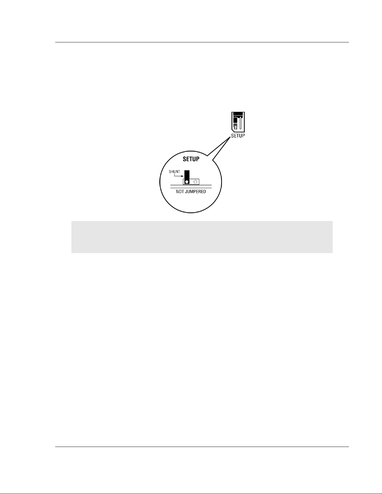
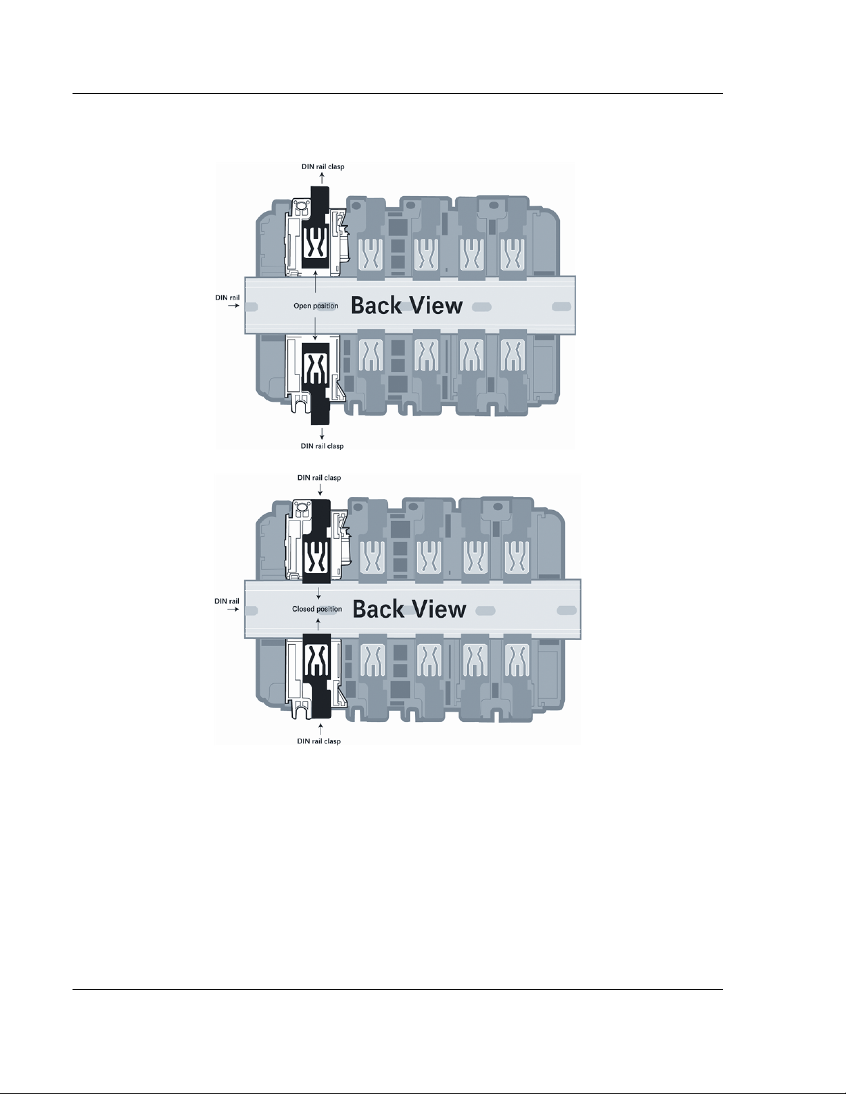
1.5 Installing the Module
Before you attempt to install the module, make sure that the bus lever of the
adjacent module is in the unlocked (fully right) position.
Warning: This module is not hot-swappable! Always remove power from the rack before
inserting or removing this module, or damage may result to the module, the processor, or other
connected devices.
1 Align the module using the upper and lower tongue-and-groove slots with the
adjacent module and slide forward in the direction of the arrow.
2 Move the module back along the tongue-and-groove slots until the bus
connectors on the MVI69 module and the adjacent module line up with each
other.
Page 16 of 225 ProSoft Technology, Inc.
July 8, 2011
Page 17
MVI69-PDPMV1 ♦ CompactLogix or MicroLogix Platform Start Here
PROFIBUS DPV1 Master User Manual
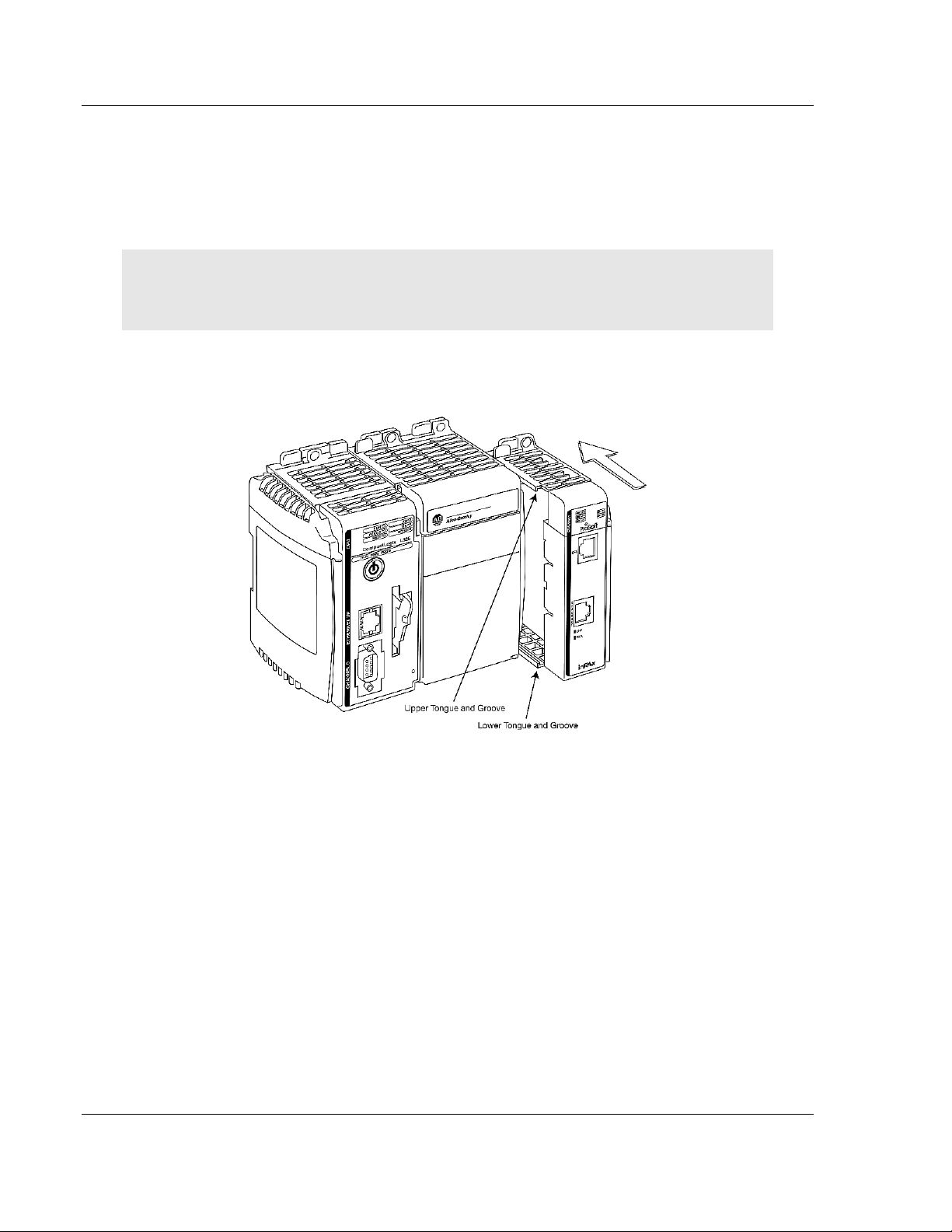
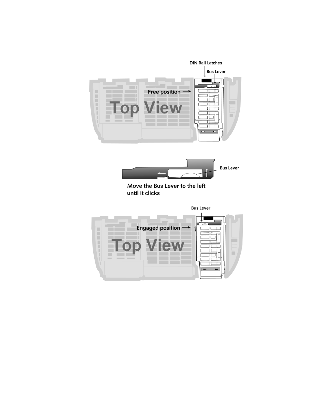
3 Push the module’s bus lever back slightly to clear the positioning tab and
move it firmly to the left until it clicks. Ensure that it is locked firmly in place.
4 Close all DIN-rail latches.
ProSoft Technology, Inc. Page 17 of 225
July 8, 2011
Page 18
Start Here MVI69-PDPMV1 ♦ CompactLogix or MicroLogix Platform
User Manual PROFIBUS DPV1 Master
5 Press the DIN-rail mounting area of the controller against the DIN-rail. The
latches will momentarily open and lock into place.
Page 18 of 225 ProSoft Technology, Inc.
July 8, 2011
Page 19

MVI69-PDPMV1 ♦ CompactLogix or MicroLogix Platform Ladder Logic
PROFIBUS DPV1 Master User Manual
2 Ladder Logic
In This Chapter
MVI69-PDPMV1 Sample Add-On Instruction Import Procedure ............ 20
Adding the Module to an Existing CompactLogix Project ...................... 39
Adding the Module to an Existing MicroLogix Project ............................ 43
Ladder logic is required for the MVI69-PDPMV1 module to work. Tasks that must
be handled by the ladder logic are module data transfer, special block handling,
and status data receipt. Additionally, a power-up handler may be needed to
handle the initialization of the module’s data and to clear any processor fault
conditions.
The sample ladder logic, on the inRAx CD-ROM, is extensively commented, to
provide information on the purpose and function of each rung. For most
applications, the sample ladder will work without modification.
ProSoft Technology, Inc. Page 19 of 225
July 8, 2011
Page 20

Ladder Logic MVI69-PDPMV1 ♦ CompactLogix or MicroLogix Platform
User Manual PROFIBUS DPV1 Master
2.1 MVI69-PDPMV1 Sample Add-On Instruction Import Procedure
Note: This section only applies if you are using a CompactLogix processor running RSLogix 5000
version 16 or higher. If you are configuring the MVI69-PDPMV1 module with an earlier version of
RSLogix 5000, please refer to Adding the Module to an Existing CompactLogix Project (page 39). If
you are using a MicroLogix processor, please see Adding the Module to an Existing MicroLogix
Project (page 43).
The following file is required before you start this procedure. Copy the file from
the ProSoft Solutions CD-ROM, or download it from
www.prosoft-technology.com.
File Name Description
MVI69PDPMV1(60)_AddOn_Rung_v1_3.L5X
MVI69PDPMV1(120)_AddOn_Rung_v1_3.L5X
MVI69PDPMV1(240)_AddOn_Rung_v1_3.L5X
MVI69PDPMV1(240)_AddOn_Rung_v1_4.L5X
L5X file contains the Add-On instruction, the
User-defined Data Types, data objects and ladder
logic required to set up the MVI69-PDPMV1
module.
Choose the file with the block size (60, 120 or
240) to match your application.
L5X file contains all of the standard items
(above), plus additional items for the Add-On
instruction, the User-defined Data Types, data
objects and ladder logic required to set up the
MVI69-PDPMV1 module to act as a PROFIBUS
Acyclic Class 2 Master.
Class 2 sample ladder currently available only for
Backplane Transfer Size of 240.
Page 20 of 225 ProSoft Technology, Inc.
July 8, 2011
Page 21
MVI69-PDPMV1 ♦ CompactLogix or MicroLogix Platform Ladder Logic
PROFIBUS DPV1 Master User Manual
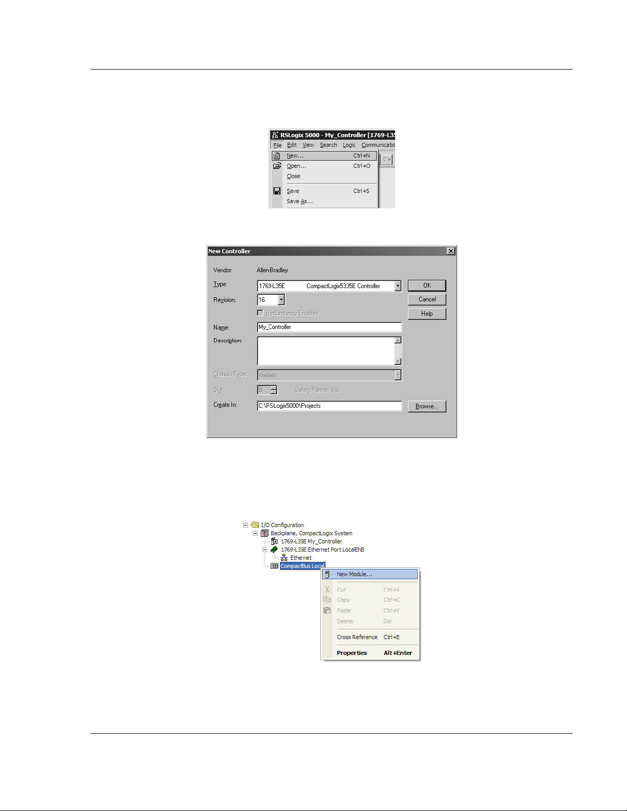
2.1.1 Creating a New RSLogix5000 Project
1 Open the FILE menu, and then choose NEW.
2 Select Revision 16.
2.1.2 Creating the Module
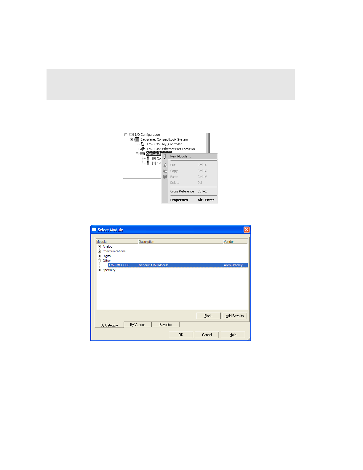
1 Right-click I/O CONFIGURATION and choose NEW MODULE.
ProSoft Technology, Inc. Page 21 of 225
July 8, 2011
Page 22
Ladder Logic MVI69-PDPMV1 ♦ CompactLogix or MicroLogix Platform
User Manual PROFIBUS DPV1 Master
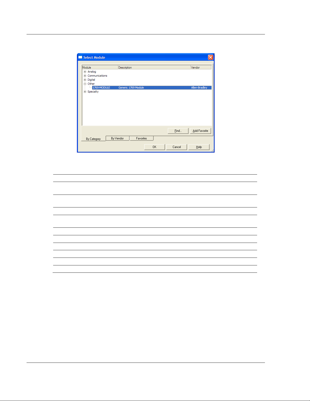
2 Select 1769-MODULE.
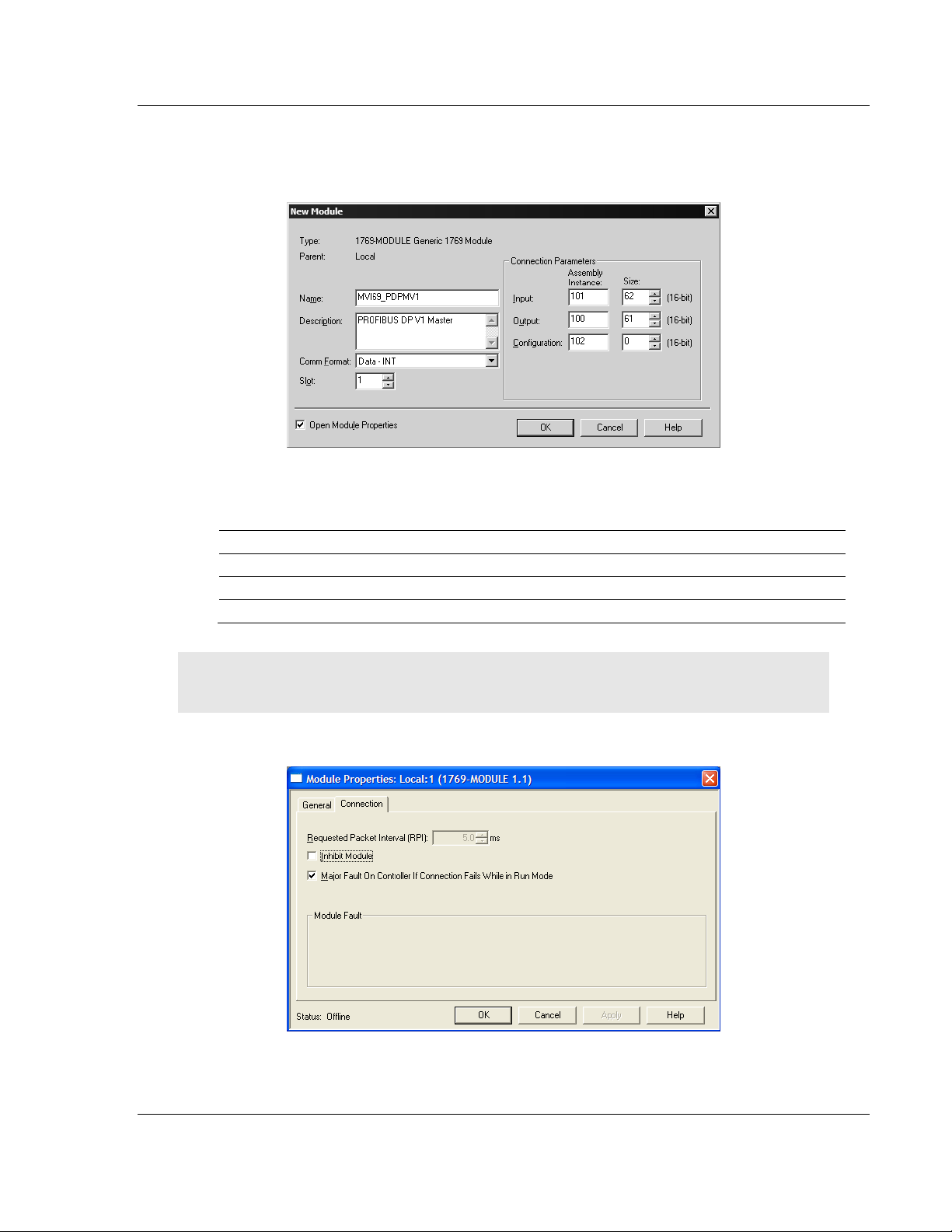
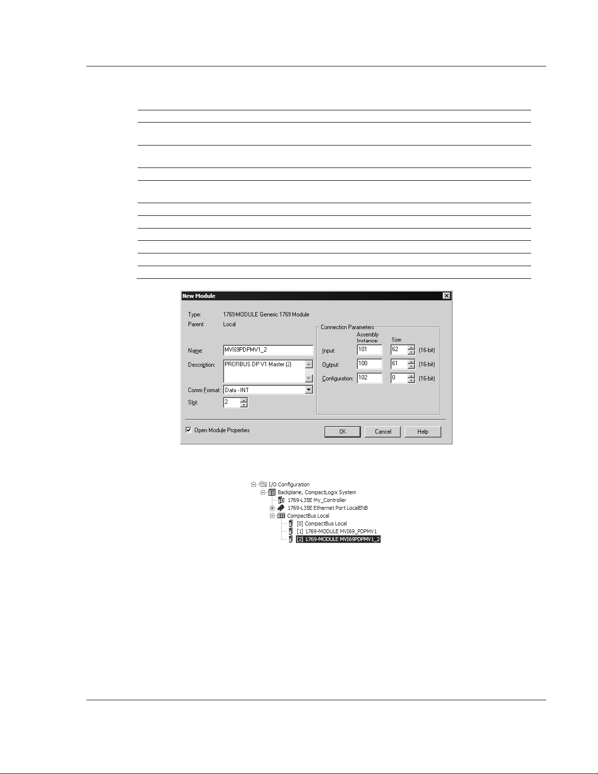
3 Set the Module Properties values as follows:
Parameter Value
Name
Description
Comm Format
Slot
Input Assembly Instance
Input Size
Output Assembly Instance
Output Size
Configuration Assembly Instance
Configuration Size
Enter a module identification string. Example:
MVI69PDPMV1
Enter a description for the module. Example: PROFIBUS
DPV1 MASTER
Select D
Enter the slot number in the rack where the MVI69-
PDPMV1 module will be installed.
101
62 / 122 / 242
100
61 / 121 / 241
102
0
ATA-INT
Page 22 of 225 ProSoft Technology, Inc.
July 8, 2011
Page 23
MVI69-PDPMV1 ♦ CompactLogix or MicroLogix Platform Ladder Logic
PROFIBUS DPV1 Master User Manual
4 The following illustration shows an example where the module was
configured for a block transfer size of 60 words (input block size = 62 words,
output block size = 61 words):
Enter the Input Block Size and Output Block Size parameters according to
the Block Transfer Size to use:
Block Transfer Size Input Block Size Output Block Size
60 62 61
120 122 121
240 242 241
Important: You must set the Block Transfer Size in ProSoft Configuration Builder to match the
block size for the Add-On Instruction, otherwise the module may not function correctly.
5 On the C
ONNECTION tab, check or un-check, as desired the Major fault option.
ProSoft Technology, Inc. Page 23 of 225
July 8, 2011
Page 24
Ladder Logic MVI69-PDPMV1 ♦ CompactLogix or MicroLogix Platform
User Manual PROFIBUS DPV1 Master
Now the MVI69-PDPMV1 module will be visible at the I/O Configuration section.
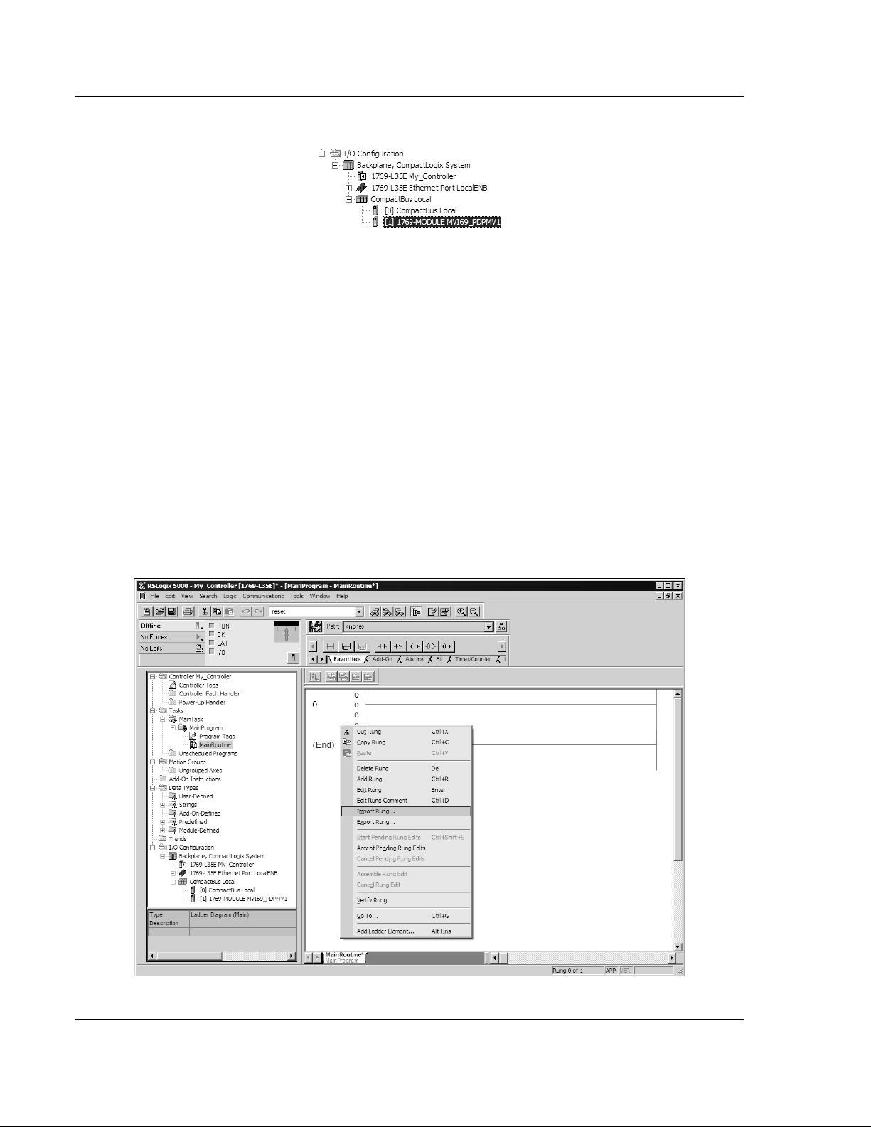
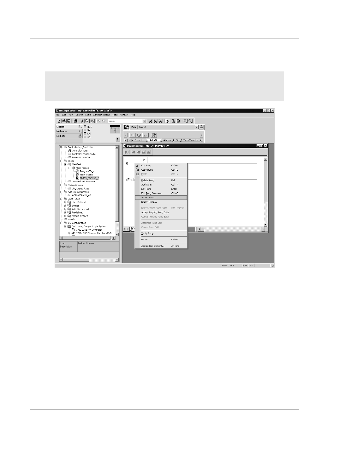
2.1.3 Importing the Ladder Rung
1 Open your application in RSLogix 5000.
2 To create a new routine, expand the T
TASK folder.
3 On the M
AIN PROGRAM folder, click the right mouse button to open a shortcut
menu. On the shortcut menu, choose N
4 In the New Routine dialog box, enter the name and description of your
routine, and then click OK. In this example we are demonstrating the
importing of the ladder rung using the default MainRoutine. In the case where
you create a routine by an other name for placing the Add-On Instruction,
then in your original routine where your other ladder logic is located you need
to add a rung with a jump instruction to the new routine holding the Add-On
Instruction.
5 Select an empty rung in the new routine, and then click the right mouse
button to open a shortcut menu. On the shortcut menu, choose I
ASKS folder, and then expand the MAIN
EW ROUTINE.
MPORT RUNG.
Page 24 of 225 ProSoft Technology, Inc.
July 8, 2011
Page 25
MVI69-PDPMV1 ♦ CompactLogix or MicroLogix Platform Ladder Logic
PROFIBUS DPV1 Master User Manual
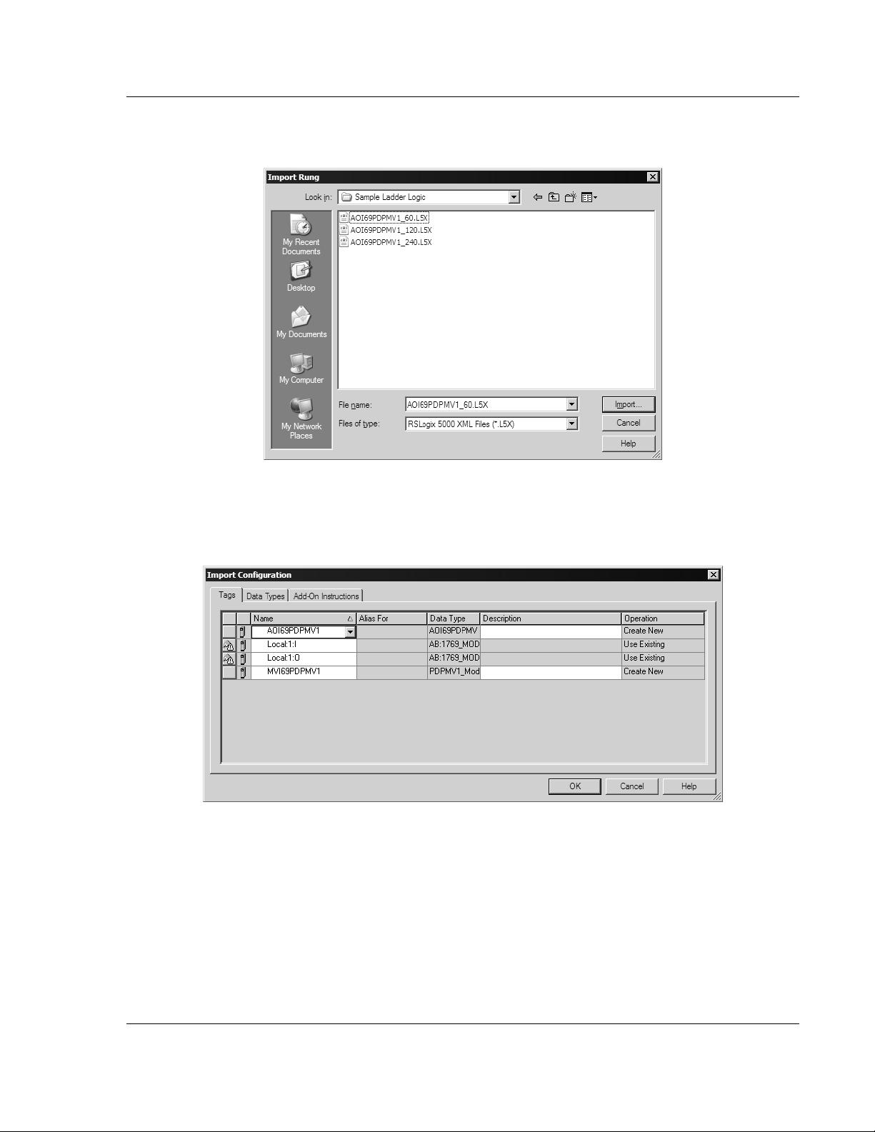
6 Select the AOI69PDPMV1_60.L5X file for the block size you selected for the
module (60, 120 or 240).
7 The following window will be displayed showing the controller tags to be
created during the import procedure: If desired, the description, "MVI69PDPMV1 Interface AOI" may be typed into the description field for
AOI69PDPMV1_60.L5X file.
ProSoft Technology, Inc. Page 25 of 225
July 8, 2011
Page 26
Ladder Logic MVI69-PDPMV1 ♦ CompactLogix or MicroLogix Platform
User Manual PROFIBUS DPV1 Master
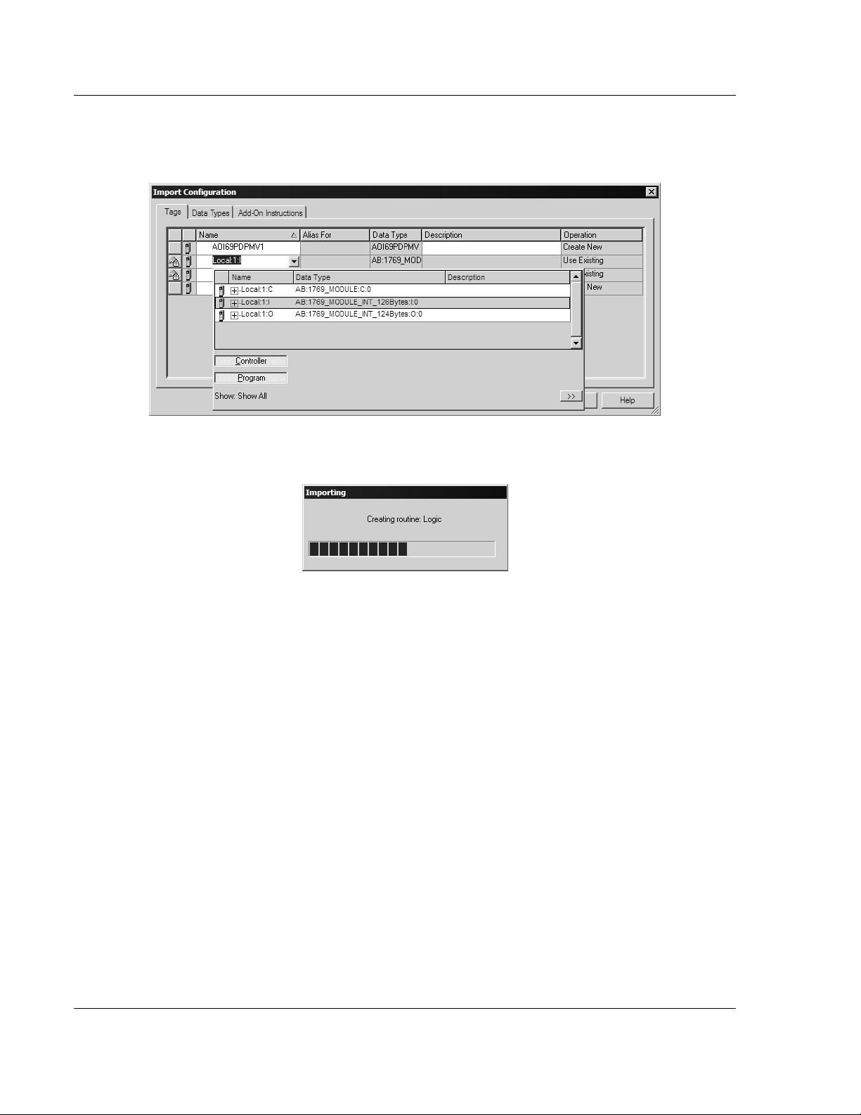
8 If you are using the module in a different slot (or remote rack), select the
correct connection input and output variables associated to the module. If
your module is located in slot 1 of the local rack, this step is not required.
Click OK to confirm the import. RSLogix will indicate that the import is in
progress:
Page 26 of 225 ProSoft Technology, Inc.
July 8, 2011
Page 27
MVI69-PDPMV1 ♦ CompactLogix or MicroLogix Platform Ladder Logic
PROFIBUS DPV1 Master User Manual
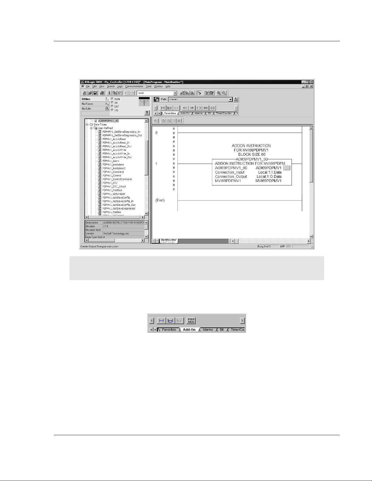
The imported rung will contain the Add-On Instruction as shown in the
following illustration. Notice that the block size is determined by the Add-On
Instruction that you imported.
Important: You must set the Block Transfer Size in ProSoft Configuration Builder to match the
block size for the Add-On Instruction, otherwise the module may not function correctly.
The procedure has also imported new user-defined data types, data objects
and the Add-On Instruction to be used at your project.
ProSoft Technology, Inc. Page 27 of 225
July 8, 2011
Page 28
Ladder Logic MVI69-PDPMV1 ♦ CompactLogix or MicroLogix Platform
User Manual PROFIBUS DPV1 Master
2.1.4 Adding Multiple Modules (Optional)
Important: If your application requires more than one MVI69-PDPMV1 module into the same
project, follow the steps below and make certain that both modules are assigned identical Block
Transfer Sizes.
1 In the I/O
shortcut menu, and then choose N
2 Select 1769-MODULE.
CONFIGURATION folder, click the right mouse button to open a
EW MODULE.
Page 28 of 225 ProSoft Technology, Inc.
July 8, 2011
Page 29
MVI69-PDPMV1 ♦ CompactLogix or MicroLogix Platform Ladder Logic
PROFIBUS DPV1 Master User Manual
3 Fill the module properties as follows:
Parameter Value
Name
Description Enter a description for the module. Example: PROFIBUS
Comm Format
Slot
Input Assembly Instance
Input Size
Output Assembly Instance
Output Size
Configuration Assembly Instance
Configuration Size
Enter a module identification string. Example:
MVI69PDPMV1_2
DPV1 MASTER
Select D
Enter the slot number in the rack where the MVI69-
PDPMV1 module will be located.
101
62 / 122 / 242
100
61 / 121 / 241
102
0
ATA-INT
4 Click OK to confirm. The new module is now visible:
5 Expand the T
6 On the M
menu. On the shortcut menu, choose N
ASKS folder, and then expand the MAINTASK folder.
AINPROGRAM folder, click the right mouse button to open a shortcut
EW ROUTINE.
7 In the New Routine dialog box, enter the name and description of your
routine, and then click OK.
ProSoft Technology, Inc. Page 29 of 225
July 8, 2011
Page 30
Ladder Logic MVI69-PDPMV1 ♦ CompactLogix or MicroLogix Platform
User Manual PROFIBUS DPV1 Master
8 Select an empty rung in the new routine, and then click the right mouse
button to open a shortcut menu. On the shortcut menu, choose I
MPORT RUNG.
Note: It is not necessary to create a completely new routine. It is possible to add the MVI69-
PDPMV1_2 module in the previously created routine. If you need to create a new routine, insert a
jump instruction in the previous routine to the new routine.
Page 30 of 225 ProSoft Technology, Inc.
July 8, 2011
Page 31

MVI69-PDPMV1 ♦ CompactLogix or MicroLogix Platform Ladder Logic
PROFIBUS DPV1 Master User Manual
9 Select the AOI69PDPMV1_60.L5X file for the block size you selected for the
module (60, 120 or 240).
10 The following window will be displayed showing the tags to be imported:
ProSoft Technology, Inc. Page 31 of 225
July 8, 2011
Page 32

Ladder Logic MVI69-PDPMV1 ♦ CompactLogix or MicroLogix Platform
User Manual PROFIBUS DPV1 Master
11 Associate the I/O connection variables to the correct module. The default
values are Local:1:I and Local:1:O. These require re-assignment to the new
module's location.
12 Change the default tags AOI69PDPMV1 and MVI69PDPMV1 to avoid conflict
with existing tags. In this step, you should append a string to the default tag
names, such as "_2", as shown in the following illustration.
Page 32 of 225 ProSoft Technology, Inc.
July 8, 2011
Page 33

MVI69-PDPMV1 ♦ CompactLogix or MicroLogix Platform Ladder Logic
PROFIBUS DPV1 Master User Manual
13 You will be prompted to confirm your change. Click OK to continue.
ProSoft Technology, Inc. Page 33 of 225
July 8, 2011
Page 34

Ladder Logic MVI69-PDPMV1 ♦ CompactLogix or MicroLogix Platform
User Manual PROFIBUS DPV1 Master
If the second module's logic was created in a new routine, enter a rung in the
Main routine with a JSR instruction to the new routine to enable the PLC logic to
communicate with both modules.
The setup procedure is now complete. Save the project and download the
application to your CompactLogix processor.
Page 34 of 225 ProSoft Technology, Inc.
July 8, 2011
Page 35

MVI69-PDPMV1 ♦ CompactLogix or MicroLogix Platform Ladder Logic
PROFIBUS DPV1 Master User Manual
2.1.5 Connecting Your PC to the Processor
1 Connect the right-angle connector end of the cable to your controller at the
communications port.
2 Connect the straight connector end of the cable to the serial port on your
computer.
ProSoft Technology, Inc. Page 35 of 225
July 8, 2011
Page 36

Ladder Logic MVI69-PDPMV1 ♦ CompactLogix or MicroLogix Platform
User Manual PROFIBUS DPV1 Master
2.1.6 Downloading the Sample Program to the Processor
Note: The key switch on the front of the CompactLogix processor must be in the REM or PROG
position.
1 If you are not already online to the processor, open the C
menu, and then choose DOWNLOAD. RSLogix will establish communication
with the processor.
2 When communication is established, RSLogix will open a confirmation dialog
box. Click the D
OWNLOAD button to transfer the sample program to the
processor.
OMMUNICATIONS
3 RSLogix will compile the program and transfer it to the processor. This
process may take a few minutes.
4 When the download is complete, RSLogix will open another confirmation
dialog box. Click OK
to switch the processor from PROGRAM mode to RUN
mode.
Note: If you receive an error message during these steps, refer to your RSLogix documentation to
interpret and correct the error.
Page 36 of 225 ProSoft Technology, Inc.
July 8, 2011
Page 37

MVI69-PDPMV1 ♦ CompactLogix or MicroLogix Platform Ladder Logic
PROFIBUS DPV1 Master User Manual
Configuring the RSLinx Driver for the PC COM Port
If RSLogix is unable to establish communication with the processor, follow these
steps.
1 Open RSLinx.
2 Open the C
OMMUNICATIONS menu, and choose CONFIGURE DRIVERS.
This action opens the Configure Drivers dialog box.
Note: If the list of configured drivers is blank, you must first choose and configure a driver from the
Available Driver Types list. The recommended driver type to choose for serial communication with
the processor is RS-232 DF1 Devices.
ProSoft Technology, Inc. Page 37 of 225
July 8, 2011
Page 38

Ladder Logic MVI69-PDPMV1 ♦ CompactLogix or MicroLogix Platform
User Manual PROFIBUS DPV1 Master
3 Click to select the driver, and then click CONFIGURE. This action opens the
Configure RS-232 DF1 Devices dialog box.
4 Click the A
UTO-CONFIGURE button. RSLinx will attempt to configure your
serial port to work with the selected driver.
5 When you see the message Auto Configuration Successful, click the OK
button to dismiss the dialog box.
Note: If the auto-configuration procedure fails, verify that the cables are connected correctly
between the processor and the serial port on your computer, and then try again. If you are still
unable to auto-configure the port, refer to your RSLinx documentation for further troubleshooting
steps.
Page 38 of 225 ProSoft Technology, Inc.
July 8, 2011
Page 39

MVI69-PDPMV1 ♦ CompactLogix or MicroLogix Platform Ladder Logic
PROFIBUS DPV1 Master User Manual
2.2 Adding the Module to an Existing CompactLogix Project
Important: The MVI69-PDPMV1 module has a power supply distance rating of 2 (L43 and L45
installations on first 2 slots of 1769 bus).
If you are installing and configuring the module with a CompactLogix controller,
follow these steps. If you are using a MicroLogix controller, refer to the next
section.
1 Add the MVI69-PDPMV1 module to the project. Right-click the mouse button
on the I/O
display a pop-up menu. Select the N
CONFIGURATION menu.
CONFIGURATION option in the Controller Organization window to
EW MODULE option from the I/O
This action opens the Select Module dialog box:
ProSoft Technology, Inc. Page 39 of 225
July 8, 2011
Page 40

Ladder Logic MVI69-PDPMV1 ♦ CompactLogix or MicroLogix Platform
User Manual PROFIBUS DPV1 Master
2 Select the 1769-Module (Generic 1769 Module) from the list and click OK.
3 Enter the Name, Description and Slot options for your application, using the
values in the illustration above. You must select the Comm Format as D
ATA -
INT in the dialog box, otherwise the module will not communicate over the
backplane of the CompactLogix rack.
4 Configure the Connection Parameters to match to the Block Transfer Size
parameter in the configuration file. Use the values in the table corresponding
with the block transfer size you configured.
Block Transfer Size = 60
Field Recommended Value
Type 1769-MODULE Generic 1769 Module
Parent Local
Name MVI69
Description MVI69 Application Module
Comm Format Data - INT
Slot The slot number in the rack where the module is installed
Input Assembly Instance 101
Input Size
Output Assembly Instance 100
Output Size
Configuration Assembly Instance 102
Configuration Size
62
61
0
Page 40 of 225 ProSoft Technology, Inc.
July 8, 2011
Page 41

MVI69-PDPMV1 ♦ CompactLogix or MicroLogix Platform Ladder Logic
PROFIBUS DPV1 Master User Manual
Block Transfer Size = 120
Field Recommended Value
Type 1769-MODULE Generic 1769 Module
Parent Local
Name MVI69
Description MVI69 Application Module
Comm Format Data - INT
Slot The slot number in the rack where the module is installed
Input Assembly Instance 101
Input Size
Output Assembly Instance 100
Output Size
Configuration Assembly Instance 102
Configuration Size
122
121
0
Block Transfer Size = 240
Field Recommended Value
Type 1769-MODULE Generic 1769 Module
Parent Local
Name MVI69
Description MVI69 Application Module
Comm Format Data - INT
Slot The slot number in the rack where the module is installed
Input Assembly Instance 101
Input Size
Output Assembly Instance 100
Output Size
Configuration Assembly Instance 102
Configuration Size
242
241
0
ProSoft Technology, Inc. Page 41 of 225
July 8, 2011
Page 42

Ladder Logic MVI69-PDPMV1 ♦ CompactLogix or MicroLogix Platform
User Manual PROFIBUS DPV1 Master
5 Click NEXT to continue.
6 Select the Requested Packet Interval value for scanning the I/O on the
module. This value represents the minimum frequency at which the module
will handle scheduled events. It should not be set to less than 1 millisecond.
Values between 5 and 10 milliseconds should work with most applications.
AVE the module. Click OK to dismiss the dialog box. The Controller
7 S
Organization window now displays the module's presence. The following
illustration shows the Controller Organization window:
8 Copy the user-defined data types from the sample program.
9 Copy the controller tags from the sample program.
10 Copy the ladder rungs from the sample program.
11 Save and download (page 36) the new application to the controller and place
it in RUN mode.
Page 42 of 225 ProSoft Technology, Inc.
July 8, 2011
Page 43

MVI69-PDPMV1 ♦ CompactLogix or MicroLogix Platform Ladder Logic
PROFIBUS DPV1 Master User Manual
2.3 Adding the Module to an Existing MicroLogix Project
If you are installing and configuring the module with a MicroLogix controller,
follow these steps. If you are using a CompactLogix controller, refer to the
previous section.
The first step in setting up the processor ladder file is to define the I/O type
module to the system. Start RSLogix 500, and follow these steps:
1 In RSLogix, open your existing application, or start a new application,
depending on your requirements.
2 Double-click the
project tree. This action opens the
I/O CONFIGURATION icon located in the Controller folder in the
I/O Configuration dialog box.
3 In the
I/O Configuration dialog box, select "OTHER - REQUIRES I/O CARD TYPE
ID" at the bottom of the list in the right pane, and then double-click to open
the "Other" type IO card dialog box.
4 Enter the values shown in the following illustration to define the module
correctly for the MicroLogix processor, and then click OK
to save your
configuration.
ProSoft Technology, Inc. Page 43 of 225
July 8, 2011
Page 44

Ladder Logic MVI69-PDPMV1 ♦ CompactLogix or MicroLogix Platform
User Manual PROFIBUS DPV1 Master
The Input Words and Output Words parameters will depend on the Block
Transfer Size parameter you specify in the configuration file. Use the values
from the following table.
Block Transfer Size Input Words Output Words
60
120
240
62 61
122 121
242 241
5 Click OK
to continue.
6 After completing the module setup, the I/O Configuration dialog box will
display the module's presence.
The last step is to add the ladder logic. If you are using the example ladder logic,
adjust the ladder to fit your application.
Download the new application to the controller and place the processor in RUN
mode. If you encounter errors, refer to Diagnostics and Troubleshooting (page
133) for information on how to connect to the module's Config/Debug port to use
its troubleshooting features.
Page 44 of 225 ProSoft Technology, Inc.
July 8, 2011
Page 45

MVI69-PDPMV1 ♦ CompactLogix or MicroLogix Platform Module Setup
PROFIBUS DPV1 Master User Manual
3 Module Setup
In This Chapter
Connecting Your PC to the Module ....................................................... 46
Configuring the Module ......................................................................... 47
Backing Up the Project .......................................................................... 68
Downloading the Project to the Module Using a Serial COM Port ......... 70
Downloading the Project to the Module Using CIPconnect ................... 73
This section contains the setup procedure, data, and ladder logic for successful
application of the MVI69-PDPMV1 module. Each step in the setup procedure is
defined in order to simplify the use of the module.
Important: Before connecting the cables, please insert the supplied PROFIBUS adaptor in the
PROFIBUS port on the MVI69 module. This adaptor provides additional space between the front of
the module and the shell of the PROFIBUS cable, allowing the PROFIBUS cable to connect
without interfering with cables connected to the Configuration/Debug port on the module. Refer to
the following illustration for the correct cabling configuration.
ProSoft Technology, Inc. Page 45 of 225
July 8, 2011
Page 46

Module Setup MVI69-PDPMV1 ♦ CompactLogix or MicroLogix Platform
User Manual PROFIBUS DPV1 Master
3.1 Connecting Your PC to the Module
With the module securely mounted, connect your PC to the Configuration/Debug
port using the RJ45-DB-9 Serial Adapter Cable and the Null Modem Cable
included in the package with the MVI69-PDPMV1 module.
1 Connect the RJ45-DB-9 Serial Adapter Cable to the Null Modem Cable.
2 Insert the RJ45 cable connector from the RJ45-DB-9 cable into the
Configuration/Debug port of the module.
3 Attach the other end to the serial port on your PC.
Page 46 of 225 ProSoft Technology, Inc.
July 8, 2011
Page 47

MVI69-PDPMV1 ♦ CompactLogix or MicroLogix Platform Module Setup
PROFIBUS DPV1 Master User Manual
3.2 Configuring the Module
ProSoft Technology has provided a configuration tool called ProSoft
Configuration Builder (PCB) that will help you with the following tasks:
Creating a configuration project
Setting module parameters
Configuring the PROFIBUS network (Master and slaves)
Calculating checksums
Copying the project to the module.
The following topics of this chapter explain each task step-by-step.
3.2.1 Setting Up the Project
To begin, start ProSoft Configuration Builder (PCB). If you have used other
Windows configuration tools before, you will find the screen layout familiar.
PCB’s window consists of a tree view on the left, an information pane and a
configuration pane on the right side of the window. When you first start PCB, the
tree view consists of folders for Default Project and Default Location, with a
Default Module in the Default Location folder. The illustration below shows the
PCB window with a new project.
ProSoft Technology, Inc. Page 47 of 225
July 8, 2011
Page 48

Module Setup MVI69-PDPMV1 ♦ CompactLogix or MicroLogix Platform
User Manual PROFIBUS DPV1 Master
First, add the MVI69-PDPMV1 module to the project.
1 Use the mouse to select D
EFAULT MODULE in the tree view, and then click the
right mouse button to open a shortcut menu.
2 On the shortcut menu, select C
HOOSE MODULE TYPE. This action opens the
Choose Module Type dialog box.
3 In the Product Line Filter area of the dialog box, select MVI69. In the Select
Module Type dropdown list, select MVI69-PDPMV1, and then click OK to
save your settings and return to the ProSoft Configuration Builder window.
Page 48 of 225 ProSoft Technology, Inc.
July 8, 2011
Page 49

MVI69-PDPMV1 ♦ CompactLogix or MicroLogix Platform Module Setup
PROFIBUS DPV1 Master User Manual
3.2.2 Setting Module Parameters
Notice that the contents of the information pane and the configuration pane
changed when you added the MVI69-PDPMV1 module to the project. The red X
icon indicates that the module’s configuration is incomplete.
In the following steps, you will provide the missing information to begin
configuring the module.
1 Click the plus sign
then expand the MVI69
2 Double-click the MVI
[+] next to the module to expand the module tree, and
PDPM-V1 tree.
PROFIBUS MASTER DPV1 object. This action opens the
Edit dialog box.
ProSoft Technology, Inc. Page 49 of 225
July 8, 2011
Page 50

Module Setup MVI69-PDPMV1 ♦ CompactLogix or MicroLogix Platform
User Manual PROFIBUS DPV1 Master
3 In the Edit dialog box, configure the values for Input Data Size and Output
Data Size (PROFIBUS input and output point words) to match the values
required by your application. To change a value, select the parameter to
modify in the left pane, and then type the new value in the edit field in the
right pane.
4 When you have finished updating the values, click OK to save your settings
and return to the ProSoft Configuration Builder window.
At this time, you may wish to rename the Default Project and Default Location
folders in the tree view.
To rename an object
1 Select the object, and then click the right mouse button to open a shortcut
menu. From the shortcut menu, choose R
ENAME.
2 Type the name to assign to the object.
3 Click away from the object to save the new name.
Page 50 of 225 ProSoft Technology, Inc.
July 8, 2011
Page 51

MVI69-PDPMV1 ♦ CompactLogix or MicroLogix Platform Module Setup
PROFIBUS DPV1 Master User Manual
3.2.3 Configuring the PROFIBUS Master
In this task, you will configure the PROFIBUS Master, and then add PROFIBUS
slaves to the network. When this step is complete, you will download the
configuration information to the MVI69 module. You will also export the I/O maps
for the processor.
1 In ProSoft Configuration Builder tree view, click [+]
PDPMV1 tree, and then double-click the PROFIBUS
opens the PDPMV1 PROFIBUS Master Setup dialog box.
2 On the Master Setup dialog box, click the C
ONFIGURE PROFIBUS button.
This action opens the ProSoft Configuration Builder for PROFIBUS
application.
3 Click [+] to expand the PROFIBUS Master tree.
4 Drag the PROFIBUS Master icon into the Bus Configuration window. This is
automatically done by the software for new applications.
to expand the MVI69-
DP icon. This action
ProSoft Technology, Inc. Page 51 of 225
July 8, 2011
Page 52

Module Setup MVI69-PDPMV1 ♦ CompactLogix or MicroLogix Platform
User Manual PROFIBUS DPV1 Master
5 Double-click the PROFIBUS MASTER icon in the Bus Configuration window.
This action opens the Master Properties dialog box.
6 On the Common tab, name your PROFIBUS drop.
Note: The PROFIBUS tab contains the address setting and advanced configuration settings for the
Master. The default settings on this tab work best in most applications.
7 Click OK to save your changes and return to the Bus Configuration window.
Page 52 of 225 ProSoft Technology, Inc.
July 8, 2011
Page 53

MVI69-PDPMV1 ♦ CompactLogix or MicroLogix Platform Module Setup
PROFIBUS DPV1 Master User Manual
3.2.4 Installing the GSD Files
The GSD configuration files contain information on PROFIBUS slaves that you
can configure as part of your PROFIBUS network. In order for this configuration
information to be available in ProSoft Configuration Builder, you must install the
GSD files.
To install GSD files manually
1 In ProSoft Configuration Builder tree view, click [+] to expand the MVI69-
PDPMV1 tree, and then double-click the PROFIBUS
opens the PDPMV1 PROFIBUS Master Setup dialog box.
2 Click the C
ONFIGURE PROFIBUS button. This action opens the ProSoft
Configuration Builder for PROFIBUS application.
3 Open the T
OOLS menu, and then choose INSTALL NEW GS* FILE. This action
opens a dialog box that allows you to browse for the location of the GSD
configuration files to install.
4 Choose the file to install, and then click O
PEN. If the file already exists in the
configuration file path, you will be prompted to overwrite the file.
5 You will be prompted to associate the GSD configuration file with a bitmap
image of the slave device. Use the File / Open dialog box to browse for the
location of the image file to use.
DP icon. This action
Tip: GSD configuration files for popular PROFIBUS slaves and ProSoft Technology modules are
included with the installation. If you have other GSD files for your PROFIBUS slaves, copy them
into C:\Documents and Settings\All Users\Application Data\ProSoft\GSD (Windows XP / 2000) or
C:\My Documents\ (Windows 98) and ProSoft Configuration Builder will load them automatically.
3.2.5 Configuring the PROFIBUS Slaves
There are two essential steps to configuring a slave:
1 Add the slave in ProSoft Configuration Builder (PCB) as a device connected
to the PROFIBUS Master, specifying the slave address and any necessary
input and output configuration. Download the PROFIBUS Master
configuration to the MVI69-PDPMV1 module.
2 Configure the slave (using PCB or the configuration tool supplied by the
manufacturer, for some PROFIBUS slaves). Verify that the slave address
configured in the slave module matches the slave address configured in PCB.
Download the PROFIBUS Slave configuration to the slave module.
Using The Autoscan Feature
The concept of Automatic network scanning means that the user can instruct the
Bus Configuration window to automatically gather information about slaves that
are connected to the network. When the scan is completed the user can adopt
the detected slaves to the bus configuration and download to the Master.
ProSoft Technology, Inc. Page 53 of 225
July 8, 2011
Page 54

Module Setup MVI69-PDPMV1 ♦ CompactLogix or MicroLogix Platform
User Manual PROFIBUS DPV1 Master
This is a quick way to get a network up and running. However, one should be
aware that it is not guaranteed that any particular slave will enter data exchange
since the user parameter data might not match. This is especially obvious if no
associated GSD-file is found during the network scan, this means that no user
parameter data would be sent to the slave.
N
ETWORK SCAN is selectable from the Online menu as well as from the drop-
down menu for the M
ASTER icon.
The only prerequisite for scanning the network is that the project consists of a
Master with no slaves assigned to it. If a network scan is initiated and the project
already contains slaves, a message window similar to the one below will appear.
When the window is closed the network scan will be omitted.
When a network scan is initiated, the PROFIBUS Master Configuration window
will download the Master bus parameters (baudrate etc.).
Page 54 of 225 ProSoft Technology, Inc.
July 8, 2011
Page 55

MVI69-PDPMV1 ♦ CompactLogix or MicroLogix Platform Module Setup
PROFIBUS DPV1 Master User Manual
When the download is completed, the PROFIBUS Master Configuration window
will initialize the Master to operate as a Class1/Class 2 Master. In this mode it is
possible to initialize the Master even if the database does not contain any slaves.
After successful initialization, the PROFIBUS Master Configuration window will
issue the following mailboxes in order to gather information about the connected
slaves:
1 1. Send FB_APPL_GET_LIVE_LIST in order to detect connected slaves,
2 2. Send FB_APPL_GET_SLAVE_DIAG (external request) to all devices
identified as slaves according to the Live list.
3 3. Send FB_APPL_GET_SLAVE_CONFIG to all devices identified as slaves
according to the Live list.
ProSoft Technology, Inc. Page 55 of 225
July 8, 2011
Page 56

Module Setup MVI69-PDPMV1 ♦ CompactLogix or MicroLogix Platform
User Manual PROFIBUS DPV1 Master
When the information is collected the PROFIBUS Master Configuration window
will find a matching GSD-file and extract information from it. Refer to the
flowchart below for this sequence:
GSD Selection Algorithm
If two or more matching GSD-files are found, the first one found should be
selected. The other compatible files should be stored so that the user can select
one of them instead. If the user selects another GSD-file, the PROFIBUS Master
Configuration window will run through the Module Selection Algorithm (described
below) again.
Page 56 of 225 ProSoft Technology, Inc.
July 8, 2011
Page 57

MVI69-PDPMV1 ♦ CompactLogix or MicroLogix Platform Module Setup
PROFIBUS DPV1 Master User Manual
Module Selection Algorithm
The algorithm used to find modules in the GSD based on the Identifier byte(s) is
as follows:
Select the module that matches the largest number of Identifier bytes. If the GSD
contains two or more modules with the exact set of Identifier bytes, use the first
module found.
Example:
If a slave responds with identifier bytes: 0x11, 0x21, 0x31 and that the associated
GSD-file contains five modules: “A” = 0x11, “B” = 0x21, “C” = 0x31, “AB” = 0x11,
0x21 and “BC” = 0x21, 0x31. The PROFIBUS Master Configuration window will
then select modules "AB" and "C".
Note: If no matching module is found in the GSD, The PROFIBUS Master Configuration window
will display the identifier byte(s) instead.
Network scan window
The information extracted from the GSD-file(s) will be displayed in the Network
scan window.
Note: Only slaves are shown here, possible Masters connected to the network will not be listed
here!
Select
In this column all found slaves will be marked as selected by default, except for
slaves with the special address 126 (refer to the next section that describes the
Address column). Only selected slaves will be added to the PROFIBUS Master
Configuration when the A
DOPT SELECTED SLAVES button is clicked.
Address
In this column the node address of the slaves will be displayed. Found slaves
should be listed in ascending order according to their node addresses.
ProSoft Technology, Inc. Page 57 of 225
July 8, 2011
Page 58

Module Setup MVI69-PDPMV1 ♦ CompactLogix or MicroLogix Platform
User Manual PROFIBUS DPV1 Master
Special address 126 -Set Slave address
If a slave with node address 126 is detected during the network scan, the
PROFIBUS Master Configuration window will display the address in red color. It
will not be possible for the user to adopt the slave to the configuration since it is
not allowed to exchange data with devices having this address. The check box in
the Select column will be grayed out.
Page 58 of 225 ProSoft Technology, Inc.
July 8, 2011
Page 59

MVI69-PDPMV1 ♦ CompactLogix or MicroLogix Platform Module Setup
PROFIBUS DPV1 Master User Manual
To be able to adopt a slave with address 126 the user must first assign a valid
address by clicking the icon next to the node address. By doing so the Set Slave
Address dialog box is started.
Note: The Old slave address is preset to a value of 126 that is not editable (grayed out).
The PROFIBUS Master Configuration window will prevent the user from selecting
a New slave address that is already occupied by another device; this includes
detected Master stations as well. If the user selects an occupied address, a
message similar to the one shown here will open.
When an address has been successfully assigned, the PROFIBUS Master
Configuration window will update the Network scan window as shown here. The
node address will be updated to the one that the user selected in the Set Slave
dialog box. The check box in the Select column will be marked allowing the user
to adopt the slave to the configuration.
ProSoft Technology, Inc. Page 59 of 225
July 8, 2011
Page 60

Module Setup MVI69-PDPMV1 ♦ CompactLogix or MicroLogix Platform
User Manual PROFIBUS DPV1 Master
Slave
In this column the name of the slave as stated in the assigned GSD-file will be
displayed. If no matching GSD-file is found the Ident number will be displayed in
red color in the drop-down list.
Module
This column shows the name of the module(s) as stated in the assigned GSDfile, which matches the Identifier byte(s) derived from the GetCfg mailbox
message. If no GSD-file or no matching module is found the Identifier byte(s) will
be displayed in red color. If the configuration for a slave is constructed of several
modules, the modules will be listed under each other.
If there is more than one module in the GSD-file that matches the Identifer bytes,
the first matching module will be displayed in blue color in a drop-down list. The
drop-down list will contain all other matching modules so that the user can select
the desired one.
Note: Only modules that have the exact same Identifer bytes as the first matching module will be
displayed in the drop-down list.
GSD-file
This column shows the name of the GSD-file that matches the Ident number
derived from the SlaveDiag mailbox message. If there are more files with the
same Ident number in the device catalog, the first matching GSD-file will be
displayed in blue color in a drop-down list.
Page 60 of 225 ProSoft Technology, Inc.
July 8, 2011
Page 61

MVI69-PDPMV1 ♦ CompactLogix or MicroLogix Platform Module Setup
PROFIBUS DPV1 Master User Manual
This could be the case if the device catalog contains two or more brand labeled
devices, or GSD-files for two or more languages (for example NICEDEV.GSD
and NICEDEV.GSE) exist.
Note: If the user selects another GSD-file, The PROFIBUS Master Configuration window will
update the modules for that slave accordingly.
If no GSD-file is found the user will be able to copy the expected GSD to the
device catalog by clicking the icon next to the text No GSD found. This will start
the Install new GS*-file dialog box. When the file is installed, the PROFIBUS
Master Configuration window will verify that the installed file matches the slave
and update the modules for the slave accordingly.
Rescan
Pressing the Y
ES button will trigger a new network scan. Before proceeding with
the scan a message similar to the one below will appear. If a new scan is
accepted, detected slaves found during the previous scan will be lost.
If no slaves are found a message similar to the one below will appear. The same
message will also show up if no slaves are found during the initial scan (for
example when selecting S
CAN NETWORK from the Online menu).
ProSoft Technology, Inc. Page 61 of 225
July 8, 2011
Page 62

Module Setup MVI69-PDPMV1 ♦ CompactLogix or MicroLogix Platform
User Manual PROFIBUS DPV1 Master
Adopt selected slaves
Pressing this button will cause all selected slaves to be adopted to the
PROFIBUS Master Configuration window. Before carrying on with this action a
message similar to the one below will appear.
If accepted, the network scan window will close and the PROFIBUS Master
Configuration window will be populated with the slaves that were found during
the network scan.
Note: The icon for slave 104 displays the Ident number since no GSD-file exists for this device.
Also observe the configuration for the very same slave at the bottom of the screen.
Note: Slave is equal to the Ident number and that the Device path and Order number/designation
fields are left empty.
Page 62 of 225 ProSoft Technology, Inc.
July 8, 2011
Page 63

MVI69-PDPMV1 ♦ CompactLogix or MicroLogix Platform Module Setup
PROFIBUS DPV1 Master User Manual
Cancel and Help
If the C
ANCEL button is pressed a message similar to the one below will appear.
If the H
ELP button is pressed the online help will start.
Scanning for Slaves Manually
In this part of the procedure, you will add and configure the PROFIBUS slaves. In
the following steps, you will add and configure a ProLinx PROFIBUS slave
module. The configuration information (.GSD file) for this module is provided on
the inRAx Solutions CD-ROM.
1 In ProSoft Configuration Builder for PROFIBUS, click the plus sign [+] to
expand the PROFIBUS DP tree.
2 Navigate to the folder containing the type of slave device to add, and then
click the plus sign [+] to expand the folder.
3 Drag the slave icon into the Bus Configuration window. The slave device
appears in the Bus Configuration window as a network location to the Master.
ProSoft Technology, Inc. Page 63 of 225
July 8, 2011
Page 64

Module Setup MVI69-PDPMV1 ♦ CompactLogix or MicroLogix Platform
User Manual PROFIBUS DPV1 Master
4 In the tree view, click the plus sign [+] to expand the slave device you added.
This action opens a list of device configuration values. The following
illustration shows the device configuration values for a ProLinx PROFIBUS
Slave. The values for other devices may be different, so you should review
the specifications for the product you are installing in order to determine the
correct values to use.
5 Drag the input and output parameters to the slot location grid below the Bus
Configuration window. This view displays the configuration data, order
number, and starting input and output addresses.
Page 64 of 225 ProSoft Technology, Inc.
July 8, 2011
Page 65

MVI69-PDPMV1 ♦ CompactLogix or MicroLogix Platform Module Setup
PROFIBUS DPV1 Master User Manual
6 Double click the slave icon to view the Slave Device properties.
In particular, note the following settings:
o Automatic PROFIBUS Address Assignment:
ProSoft Configuration Builder automatically assigns a PROFIBUS address
to each new slave. The address assignment begins at address 3, and is
incremented by 1 for each new slave added to the network. You can
change the address in the Common tab of the Slave Properties dialog
box.
o Automatic Input/Output Address Assignment:
For each new slave added to the PROFIBUS network, ProSoft
Configuration Builder automatically converts the input/output byte
addresses to word input/output addresses for the State RAM in the
processor.
7 Repeat steps 2 through 6 for all slaves you intend to place on the network.
8 When you are finished adding slaves, open the P
E
XIT to return to the Master Setup dialog box.
ROJECT menu and choose
ProSoft Technology, Inc. Page 65 of 225
July 8, 2011
Page 66

Module Setup MVI69-PDPMV1 ♦ CompactLogix or MicroLogix Platform
User Manual PROFIBUS DPV1 Master
3.2.6 Calculating the Checksums
The checksum (CRC) values are calculated from the PROFIBUS configuration
data, and compare the contents of the configuration file in the module with the
value reported by the processor. The checksum (CRC) value allows the
processor to verify that the configuration file is valid, and has not changed since
the last time the configuration file was imported to the processor. Any change to
the contents of the configuration file in either location changes the unique
numeric (CRC) value for the file.
If the checksum values do not match, the APP STATUS light illuminates on the
module.
1 On the PDPMV1 PROFIBUS Master Setup dialog box, click the C
ALCULATE
CHECKSUMS button.
2 Make a note of the checksum values so that you can enter them later if
prompted.
Note: The recommended location for the files is the My Doc uments folder on your PC. The
configuration tool for the processor will use this folder by default.
3.2.7 Printing the Processor Network Memory Map
The inRAx Data Type dialog box uses the information about your PROFIBUS
Master and slaves to display the data types you configured. You will need this
information to determine the memory areas your application will use in the
CompactLogix processor.
Page 66 of 225 ProSoft Technology, Inc.
July 8, 2011
Page 67

MVI69-PDPMV1 ♦ CompactLogix or MicroLogix Platform Module Setup
PROFIBUS DPV1 Master User Manual
To view or print the Processor Network Memory Map
1 On the Master Setup dialog box, click the SHOW MEMORY MAP button, near
the bottom of the window. This action opens the inRAx Data Type dialog box.
2 Notice that there are buttons in the Display area of the dialog box to show
inputs and outputs. These input and output maps correspond to the input and
output data you configured for the PROFIBUS slaves. Notice also that there
are check boxes to display slot numbers and PROFIBUS addresses.
3 Click P
RINT to print the input and output maps for reference. Note that you
must do this for both input and output maps.
4 When you have finished printing the processor memory maps, click OK to
close the dialog box. Click OK again to close the Master Setup dialog box.
5 Keep the printed memory maps on hand. You must refer to them when you
configure the sample ladder logic in RSLogix. The sample ladder logic
contains input and output arrays that must be cross-referenced with the
variables.
The next step is to download the project to the MVI69 module.
ProSoft Technology, Inc. Page 67 of 225
July 8, 2011
Page 68

Module Setup MVI69-PDPMV1 ♦ CompactLogix or MicroLogix Platform
User Manual PROFIBUS DPV1 Master
3.3 Backing Up the Project
In this step, you will create a backup copy of your project and configuration files.
The backup procedure saves your data for reuse on another machine, or allows
you to restore your data in the event of a system failure.
To save your project and configuration files
1 In ProSoft Configuration Builder tree view, click [+] to expand the MVI69-
PDPMV1 tree, and then double-click the PROFIBUS
opens the PDPMV1 PROFIBUS Master Setup dialog box.
2 In the PDPMV1 PROFIBUS Master Setup dialog box, click the E
MASTER CONFIG button. This action saves the PROFIBUS network
configuration for your module in an XML file. The recommended location for
this file is your My Documents folder.
Tip: You can use the XML file created by ProSoft Configuration Builder in this step to simplify the
task of configuring additional PROFIBUS network modules. Because it saves the entire network
configuration, you can add modules quickly by modifying only the items that are unique for each
device, typically the slot number and I/O addresses. To use this saved configuration, open
Windows Explorer, navigate to the folder where you saved the Master Configuration XML file, and
then drag the file onto the new PROFIBUS DP icon in the ProSoft Configuration Builder tree view.
3 In ProSoft Configuration Builder, open the F
AS.
4 Name the project file, and click
is your My Documents folder.
DP icon. This action
XPORT
ILE menu, and then choose SAVE
SAVE. The recommended location for this file
Note: All PCB project files and module-related files are automatically saved to C:\PCBExportfFiles.
A complete backup consists of the Project and Master Configuration files, plus
the GSD configuration files. The default location for the GSD files is
C:\Documents and Settings\All Users\Application Data\ProSoft\GSD (Windows
XP / 2000) or C:\My Documents\.
Page 68 of 225 ProSoft Technology, Inc.
July 8, 2011
Page 69

MVI69-PDPMV1 ♦ CompactLogix or MicroLogix Platform Module Setup
PROFIBUS DPV1 Master User Manual
PCB does this complete backup for you automatically. The default location for
these backup files is C:\PCBExportFiles. All the files associated with your PCB
configuration will be stored in a folder with the same name as the name you used
to save your PCB configuration (.ppf) file. When you exit PCB, you will be
prompted to overwrite your Export folder files.
If you have made changes to your configuration settings, you should click the
ES button every time you see this dialog box to have the backup files updated.
Y
Having all the files for your PCB configuration stored in one folder makes it easier
to transfer the application from one system to the other or to send your files to
ProSoft Technical Support when you need assistance.
ProSoft Technology, Inc. Page 69 of 225
July 8, 2011
Page 70

Module Setup MVI69-PDPMV1 ♦ CompactLogix or MicroLogix Platform
User Manual PROFIBUS DPV1 Master
3.4 Downloading the Project to the Module Using a Serial COM Port
For the module to use the settings you configured, you must download (copy) the
updated Project file from your PC to the module.
To download the project file
1 In the tree view in ProSoft Configuration Builder, click once to select the
module.
2 Right-click the module icon to open a shortcut menu. From the shortcut
menu, choose D
PC for a valid com port (this may take a few seconds). When PCB has found
a valid COM port, the Download
OWNLOAD FROM PC TO DEVICE. The program will scan your
dialog box will open.
3 Choose the COM port to use from the
D
OWNLOAD button.
dropdown list, and then click the
The module will perform a platform check to read and load its new settings.
When the platform check is complete, the status bar in the Download
box will display the message Module Running.
dialog
Page 70 of 225 ProSoft Technology, Inc.
July 8, 2011
Page 71

MVI69-PDPMV1 ♦ CompactLogix or MicroLogix Platform Module Setup
PROFIBUS DPV1 Master User Manual
3.4.1 Disabling the RSLinx Driver for the Com Port on the PC
The communication port driver in RSLinx can occasionally prevent other
applications from using the PC’s COM port. If you are not able to connect to the
module’s configuration/debug port using ProSoft Configuration Builder (PCB),
HyperTerminal or another terminal emulator, follow these steps to disable the
RSLinx driver.
1 Open RSLinx and go to C
2 Make sure that you are not actively browsing using the driver that you wish to
stop. The following shows an actively browsed network.
OMMUNICATIONS > RSWHO.
3 Notice how the DF1 driver is opened, and the driver is looking for a processor
on node 1. If the network is being browsed, then you will not be able to stop
this driver. To stop the driver your RSWho screen should look like this:
Branches are displayed or hidden by clicking on the
or the icons.
ProSoft Technology, Inc. Page 71 of 225
July 8, 2011
Page 72

Module Setup MVI69-PDPMV1 ♦ CompactLogix or MicroLogix Platform
User Manual PROFIBUS DPV1 Master
4 When you have verified that the driver is not being browsed, go to
C
OMMUNICATIONS > CONFIGURE DRIVERS.
You may see something like this:
If you see the status as running, you will not be able to use this com port for
anything other than communication to the processor. To stop the driver press
the S
TOP button on the side of the window:
5 After you have stopped the driver you will see the following.
6 You may now use the com port to connect to the debug port of the module.
Note: You may need to shut down and restart your PC before it will allow you to stop the driver
(usually only on Windows NT machines). If you have followed all of the above steps, and it will not
stop the driver, then make sure you do not have RSLogix open. If RSLogix is not open, and you
still cannot stop the driver, then reboot your PC.
Page 72 of 225 ProSoft Technology, Inc.
July 8, 2011
Page 73

MVI69-PDPMV1 ♦ CompactLogix or MicroLogix Platform Module Setup
PROFIBUS DPV1 Master User Manual
3.5 Downloading the Project to the Module Using CIPconnect
1 Right-click the MVI69-PDPMV1 module and choose DOWNLOAD FROM PC TO
DEVICE.
2 In the Select Port dropdown list, choose 1769-L3
XE. The default path
appears in the text box, as shown in the following illustration.
The CIPconnect Path Editor allows you to define the path between the PC and
the MVI69-PDPMV1 module.
Each row in the CIPconnect Path Editor corresponds to a physical rack in the
CIP path. Since bridging through multiple racks is not supported in the MVI69PDPMV1, only one row is needed for configuring the CIP path.
ProSoft Technology, Inc. Page 73 of 225
July 8, 2011
Page 74

Module Setup MVI69-PDPMV1 ♦ CompactLogix or MicroLogix Platform
User Manual PROFIBUS DPV1 Master
To use the CIPconnect Path Editor
1 Click CIP PATH EDIT to open the CIPconnect Path Editor dialog box.
Parameter Description
Source Module Source module type
Source Module IP Address IP address of the source module
Source Module Node Address
Destination Module
Destination Module Slot Number The slot number where the destination module is located
ControlNet Node address of the source module
Note: Not currently used by MVI69 modules
Select the destination module associated to the source module
in the rack. The connection between the source and destination
modules is performed through the backplane.
2 Click C
ONSTRUCT CIP PATH to build the path in text format
3 Click OK to confirm the configured path.
The following example should provide a better understanding on how to set up
the path for your network.
Page 74 of 225 ProSoft Technology, Inc.
July 8, 2011
Page 75

MVI69-PDPMV1 ♦ CompactLogix or MicroLogix Platform Module Setup
PROFIBUS DPV1 Master User Manual
3.5.1 Example
Rack 1
Slot Module Network Address
0 1769-L3xE IP=192.168.0.100
1 MVI69-PDPMV1 -
1 In the Download window, click CIP
PATH EDIT.
2 Configure the path as shown in the following illustration, and click
C
ONSTRUCT CIP PATH to build the path in text format.
ProSoft Technology, Inc. Page 75 of 225
July 8, 2011
Page 76

Module Setup MVI69-PDPMV1 ♦ CompactLogix or MicroLogix Platform
User Manual PROFIBUS DPV1 Master
3 Check the new path in the Download dialog box.
Page 76 of 225 ProSoft Technology, Inc.
July 8, 2011
Page 77

MVI69-PDPMV1 ♦ CompactLogix or MicroLogix Platform Module Setup
PROFIBUS DPV1 Master User Manual
4 Click TEST CONNECTION to verify that the physical path is available. The
following message should be displayed upon success.
5 Click D
the path.
OWNLOAD to download the configuration files to the module through
ProSoft Technology, Inc. Page 77 of 225
July 8, 2011
Page 78

Module Setup MVI69-PDPMV1 ♦ CompactLogix or MicroLogix Platform
User Manual PROFIBUS DPV1 Master
Using CIPconnect for PROFIBUS Network Monitoring
You can also monitor the PROFIBUS network through the CIPconnect path.
Refer to the PROFIBUS DP section in ProSoft Configuration Builder, and verify
the same path you have just created through the Download button. You can also
re-edit the path through the CIP Path Edit button.
1 Click C
ONFIGURE PROFIBUS.
Page 78 of 225 ProSoft Technology, Inc.
July 8, 2011
Page 79

MVI69-PDPMV1 ♦ CompactLogix or MicroLogix Platform Module Setup
PROFIBUS DPV1 Master User Manual
2 Select ONLINE-MONITOR/MODIFY to monitor the PROFIBUS network through
the CIPconnect path .
ProSoft Technology, Inc. Page 79 of 225
July 8, 2011
Page 80

Module Setup MVI69-PDPMV1 ♦ CompactLogix or MicroLogix Platform
User Manual PROFIBUS DPV1 Master
The configured slave(s) should be indicated with a green border indicating
successful PROFIBUS communication.
Page 80 of 225 ProSoft Technology, Inc.
July 8, 2011
Page 81

MVI69-PDPMV1 ♦ CompactLogix or MicroLogix Platform Mailbox Messaging
PROFIBUS DPV1 Master User Manual
4 Mailbox Messaging
In This Chapter
Mailbox Message Queuing .................................................................... 82
Sending a Mailbox Message in RSLogix 5000 ...................................... 83
Receiving Mailbox Message Responses from the Module .................... 84
Special Function Mailbox Messaging Commands ................................. 85
Mailbox Messaging Error Codes ......................................................... 128
The MVI69-PDPMV1 PROFIBUS DP Master uses a process called Mailbox
Messaging to exchange parameter data between the processor, Master, and
slave devices. This process provides a way to encapsulate and prioritize
commands and data sent between the PROFIBUS Master and slaves.
The PROFIBUS DP-V1 protocol specifies two types of data transmission
messages (telegrams): Cyclic Data Telegrams and Acyclic Data Telegrams.
Cyclic data communication is the exchange of normal slave input and output (I/O)
data and is handled automatically by the Master in a defined, recurring,
deterministic sequence based on the configuration you create in ProSoft
Configuration Builder (PCB).
Acyclic communication extends data communication beyond normal I/O data to
allow moving field device parameterization and calibration data over the bus
during runtime and to allow for extended diagnostics and alarm messages.
Acyclic data telegrams are transmitted in the gaps between cyclic data telegrams
and, therefore, have a lower priority and get less bandwidth than cyclic data.
Class 1 Acyclic message telegrams may be issued to any slave on the network
with has already been configured for Cyclic data exchange with the module's
DPV1 Master. The ability to request acyclic data from these same slaves
increases the data collection, alarming, and diagnostic capacity of the module's
DPV1 Master when communicating with DPV1 slaves that support acyclic
messaging.
The PROFIBUS DPV1 Master also supports Class 2 Acyclic messaging. This
allows the DPV1 Master to send data request telegrams to any slave node on the
PROFIBUS network, whether or not that node has been configured to exchange
cyclic data with the module's DPV1 Master. These extra Class 2 features further
expand the module Master's capability and flexibility.
Mailbox Messaging commands are incorporated into the sample ladder logic.
Mailbox messages and responses to mailbox messages are stored in mailbox
data types on the sample program or Add-On Instruction (AOI).
ProSoft Technology, Inc. Page 81 of 225
July 8, 2011
Page 82

Mailbox Messaging MVI69-PDPMV1 ♦ CompactLogix or MicroLogix Platform
User Manual PROFIBUS DPV1 Master
4.1 Mailbox Message Queuing
The MVI69-PDPMV1 module operates asynchronously on the Mailbox Messages
and as such provides for the queuing of the messages as they are received. The
queue sizes used in the module are as follows:
Queue Type
Output message from processor 126
Input messages for processor 126
Alarm messages from slaves for
processor
Queue Size
Max
100
Description
Number of messages that the MVI69 module
will queue by type of message. Note that status
of the queues can be monitored via the Queue
Message Count values.
4.1.1 Queue Timeouts
The MVI69-PDPMV1 module will only allow a message to stay in a queue for up
to 10 seconds. If the PROFIBUS Master (for output messages) or the processor
(for input and alarm messages) has not successfully received a message within
10 seconds, the module will clear the message out of the queue.
Page 82 of 225 ProSoft Technology, Inc.
July 8, 2011
Page 83

MVI69-PDPMV1 ♦ CompactLogix or MicroLogix Platform Mailbox Messaging
PROFIBUS DPV1 Master User Manual
4.2 Sending a Mailbox Message in RSLogix 5000
Note: For this procedure, you must connect a serial cable from the serial port on your PC to the
DB9M connector on the CompactLogix or MicroLogix processor.
1 Open the sample ladder logic in RSLogix 5000.
2 Open the C
3 In the Controller Organization window, double-click C
4 Expand the MVI69PDPMV1 and MVI69PDPMV1.[Mailbox]Command tags.
5 Enter [1] (number one) in the tag
MVI69PDPMV1.[Mailbox]Command.GetLiveList, and then press [E
send the mailbox message from the processor to the MVI69-PDPMV1.
OMMUNICATIONS menu, and choose GO ONLINE.
ONTROLLER TAGS.
NTER] to
6 Next, expand the tag MVI69PDPMV1.Mailbox.GetLiveList.Station, to verify
that the MVI69-PDPMV1 responded to the GetLiveList message.
For MVI69PDPMV1.Mailbox.GetLiveList.Station[1] (the PROFIBUS Master
Address), notice that the value has changed from 4 (not communicating) to 3
(Master).
For MVI69PDPMV1.Mailbox.GetLiveList.Station[125] (the PROFIBUS Slave
Address configured in the Slave Configuration procedure), notice that the
value has changed from 4 (not communicating) to 0 (Slave OK)
ProSoft Technology, Inc. Page 83 of 225
July 8, 2011
Page 84

Mailbox Messaging MVI69-PDPMV1 ♦ CompactLogix or MicroLogix Platform
User Manual PROFIBUS DPV1 Master
4.3 Receiving Mailbox Message Responses from the Module
After a mailbox message has been sent, a response from the command, usually
containing the requested data or the status of the command, is returned from the
MVI69 module to the processor. The response is returned from the MVI69PDPMV1 via the PROFIBUS Input data block.
Remembering the PROFIBUS Input Data Memory Map:
Byte Offset Name Description
0 to 72 Configuration, Status and Control data
73 Number of Messages in the In Mailbox Queue
74 Number of Messages in the Out Mailbox Queue
75 Number of Messages in the Alarm Queue
76
77 Current In Mailbox Control Index
78 Current Alarm Control Index
79 to 222 Incoming Mailbox Message data
223 to n PROF IBUS Input Data
The important section relevant to the Mailbox Messaging discussion is the
Incoming Mailbox Data section (Byte Offsets 79 to 222). Within this section of
data, the following structure exists:
Last Out Mailbox Message ID processed from Output
Image
Mailbox Message Structure: From MVI69 module
Byte Offset Type Description
79 Message ID
80 Message Info
81 Command
82 Data Size
83 Frame Count
84 Frame Number
85 Offset high
86 Offset Low
87 Extended Word 1
88 Extended Word 2
89 Extended Word 3
90 Extended Word 4
91 Extended Word 5
92 Extended Word 6
93 Extended Word 7
94 Extended Word 8
222
See individual
commands
Message ID value will match value used to generate the
outgoing mailbox message
See individual commands for data values to be entered in
each of these register locations
Page 84 of 225 ProSoft Technology, Inc.
July 8, 2011
Page 85

MVI69-PDPMV1 ♦ CompactLogix or MicroLogix Platform Mailbox Messaging
PROFIBUS DPV1 Master User Manual
4.4 Special Function Mailbox Messaging Commands
The MVI69-PDPMV1 module supports some extended PROFIBUS functions,
using a mailbox data exchange mechanism implemented in the module.
The MVI69-PDPMV1 module supports the following special functions through
this mailbox messaging scheme:
Initiated from Processor
Message Description
Set Operation Mode Controls the operating state of the PROFIBUS Master
Set Slave Mode
Get Slave Diag Gets diagnostic information from a slave
Get Slave Config Gets slave configuration
Set Slave Address Sets node address of a slave (if supported by the slave)
Get Live List Gets information from all nodes on the network
Start Slave Starts slaves dynamically
Stop Slave Stops slaves dynamically
Class 1 MSAC1 Read DPV1 acyclic read
Class 1 MSAC1 Write DPV1 acyclic write
Class 2 MSAC2 Connection Initiate Establishes a DPV1 Class 2 connection to a slave
Class 2 MSAC2 Connection Abort Terminates a DPV1 Class 2 connection to a slave
Class 2 MSAC2 Read
Class 2 MSAC2 Write
Sends special control command to one or several slaves
(Sync/Freeze)
Issues a Class 2 acyclic read request to a slave, once a
connection has been established
Issues a Class 2 acyclic write request to a slave, once a
connection has been established
ProSoft Technology, Inc. Page 85 of 225
July 8, 2011
Page 86

Mailbox Messaging MVI69-PDPMV1 ♦ CompactLogix or MicroLogix Platform
User Manual PROFIBUS DPV1 Master
DPV1 Alarm Handling: Generated by Slave Devices
Message Description
Alarm Indications
Alarm Confirmation
Spontaneous alarm indication from DPV1 slave. Structure of
data is slave-dependent
This message is sent by the MVI69 module automatically as
a confirmation to the alarm indications.
The provided Function Blocks simplify the processor logic required to implement
these messaging mailbox exchanges.
Sending a mailbox message to the MVI69-PDPMV1 module is a relatively simple
process; however, it is important to follow a certain sequence.
Page 86 of 225 ProSoft Technology, Inc.
July 8, 2011
Page 87

MVI69-PDPMV1 ♦ CompactLogix or MicroLogix Platform Mailbox Messaging
PROFIBUS DPV1 Master User Manual
Mailbox Message Structure: To MVI69 Module
Word Offset Type Description
0 Message ID
1 Message Info
2 Command
3 Data Size
4 Frame Count
5 Frame Number
6 Offset high
7 Offset Low
8 Extended Word 1
9 Extended Word 2
10 Extended Word 3
11 Extended Word 4
12 Extended Word 5
13 Extended Word 6
14 Extended Word 7
15 Extended Word 8
149
See individual
commands
Processor logic or user-set. The Message ID field is used
by the MVI69 module to detect a new message in the
PROFIBUS output data image.
When a non-zero value is detected, the message is
processed immediately. The sample ladder logic assigns
specific message IDs to different mailbox messages.
See individual commands for data values to be entered in
each of these register locations
ProSoft Technology, Inc. Page 87 of 225
July 8, 2011
Page 88

Mailbox Messaging MVI69-PDPMV1 ♦ CompactLogix or MicroLogix Platform
User Manual PROFIBUS DPV1 Master
4.4.1 Mailbox Message: Set Operating Mode
This command allows setting the operating mode of the module (STOP, CLEAR,
or OPERATE).
Parameter Description
Command Initiator Application
Command Name SET OPERATING MODE
Command Number 0200h
Fragmented No
Extended Header Data Fault information may be returned in the header of the response.
Command and Response Layout: Set Operating Mode
Message ID
Message information 4002h
Command 0002h
Data size 0000h
Frame count 0001h
Frame number 0001h
Offset high 0000h
Offset low 0000h
Extended word 1 Mode Conf. Req
Command
(ID)
Response
(ID)
0002h
0002h Set Operation Mode
0000h
0001h
0001h
0000h
0000h
Mode Conf. Req
Extended word 2 -
Extended word 3 -
Extended word 4 -
Extended word 5 -
Extended word 6 -
Extended word 7 -
Extended word 8 -
-
-
-
-
-
-
Fault Information
Page 88 of 225 ProSoft Technology, Inc.
July 8, 2011
Page 89

MVI69-PDPMV1 ♦ CompactLogix or MicroLogix Platform Mailbox Messaging
PROFIBUS DPV1 Master User Manual
Mode
40h: STOP
80h: CLEAR
C0h: OPERATE
Conf. Req.
00h: Confirmation is not required
01h: Confirmation required. All confirmations are automatically sent by the
Master; the user is not required to send a confirmation message.
Fault Information
If "Invalid Other" is returned in the Message Information word in the header of the
response, information about the fault can be found here. Refer to Return Codes
(page 129) for more information.
0100h: Invalid operating mode
FF00h: Module not initialized
ProSoft Technology, Inc. Page 89 of 225
July 8, 2011
Page 90

Mailbox Messaging MVI69-PDPMV1 ♦ CompactLogix or MicroLogix Platform
User Manual PROFIBUS DPV1 Master
4.4.2 Mailbox Message: Set Slave Mode
In addition to station-related user data transfer, which is executed automatically,
the Master can send control commands to a single slave, a group of slaves, or all
slaves simultaneously. These control commands are transmitted as multicast
commands. This permits use of sync and freeze modes for event-controlled
synchronization of the slaves.
The slaves begin sync mode when they receive a sync command from their
assigned Master. The outputs of all addressed slaves are then frozen in their
current state. During subsequent user data transmissions, the output data are
stored on the slaves, but the output states remain unchanged. The stored output
data are not sent to the outputs until the next sync command is received. Sync
mode is concluded with the unsync command.
Similarly, a freeze control command causes the addressed slaves to assume
freeze mode. In this operating mode, the states of the inputs are frozen until the
Master sends the next freeze command. Freeze mode is concluded with the
unfreeze command.
Note 1: It is only possible to send control commands when operating mode is either "CLEAR" or
"OPERATE".
Note 2: Not all slaves support this feature. Refer to the documentation for the actual slave for more
information.
Parameter Description
Command Initiator Application
Command Name SET SLAVE MODE
Command Number 0300h
Fragmented No
Extended Header Data Fault information may be returned in the header of the response.
Page 90 of 225 ProSoft Technology, Inc.
July 8, 2011
Page 91

MVI69-PDPMV1 ♦ CompactLogix or MicroLogix Platform Mailbox Messaging
PROFIBUS DPV1 Master User Manual
Command and Response Layout: Set Slave Mode
Message ID
Message information 4002h
Command 0003h
Data size 0000h
Frame count 0001h
Frame number 0001h
Offset high 0000h
Offset low 0000h
Extended word 1 Slave
Extended word 2 Control
Extended word 3 -
Extended word 4 -
Extended word 5 -
Extended word 6 -
Extended word 7 -
Extended word 8
Command
Address
Command
(ID)
Group Select
Response
Slave
Address
Control
Command
Extended Fault Information
(ID)
0002h
0003h Set Slave Mode
0000h
0001h
0001h
0000h
0000h
Group Select
-
-
-
-
Fault Information
Message Information
Refer to Message Information (page 128).
Slave Address
Range 1 to 125; 127
If the request applies for only one slave, that slave address must be entered in
the range 1 to 125. If a slave group is to be addressed, slave address should be
127 (multicast address).
ProSoft Technology, Inc. Page 91 of 225
July 8, 2011
Page 92

Mailbox Messaging MVI69-PDPMV1 ♦ CompactLogix or MicroLogix Platform
User Manual PROFIBUS DPV1 Master
Group Select
Range 01h to FFh (Bit Coded)
This parameter determines which group to address. Refer to the following
example:
b7 b6 b5 b4 b3 b2 b1 b0
Group 8 Group 7 Group 6 Group 5 Group 4 Group 3 Group 2 Group 1
Example:
To address Group 1, 2, and 4, the Group Select value should be D0h. If an
individual slave should be addressed, the correct group selection must also be
made, because the slave will ignore the message if it does not belong to the
requested group(s).
What group(s) a slave belongs to is determined during network configuration,
and is downloaded during initialization to each slave via the PROFIBUS telegram
Set_Prm.
Control Command
This parameter specifies the command to send:
Bit Explanation
0 (LSB) Reserved, set to zero
1 Reserved, set to zero
2 Unfreeze input data
3 Freeze input data
4 Unsynchronize output data
5 Synchronize output data
6 Reserved, set to zero
7 (MSB) Reserved, set to zero
Combinations of the bits (Unsync/Sync and Unfreeze/Freeze)
Bits 0 or 6 Bits 1 or 7 Explanation
0 0 No function
0 1 Function will be activated
1 0 Function will be inactive
1 1 Function will be inactive
Page 92 of 225 ProSoft Technology, Inc.
July 8, 2011
Page 93

MVI69-PDPMV1 ♦ CompactLogix or MicroLogix Platform Mailbox Messaging
PROFIBUS DPV1 Master User Manual
Fault Information and Extended Fault Information
"Fault Information" Contents "Extended Fault Information" Contents
0100h Address out of range 0200h
0A00h
FF00h Module not initialized -
Group number 0 not
permitted
Failed to send Global
Control request
-
0A00h Incorrect operation mode (Clear/Operate Only)
0150h
0250h
0350h Incorrect Control Command
0450h
Invalid Freeze Group (Group is not initiated to be
Freeze Group)
Invalid Sync Group (Group is not initiated to be
Sync Group)
No Sync -/ or Freeze groups enabled in Master
configuration
ProSoft Technology, Inc. Page 93 of 225
July 8, 2011
Page 94

Mailbox Messaging MVI69-PDPMV1 ♦ CompactLogix or MicroLogix Platform
User Manual PROFIBUS DPV1 Master
4.4.3 Mailbox Message: Get Slave Diagnostics
This command reads diagnostic data from a specified slave.
Note: The response data size depends on the actual slave implementation. Range 6 to 244.
Parameter Description
Command Initiator Application
Command Name GET SLAVE DIAGNOSTICS
Command Number 0400h
Fragmented No
Extended Header Data Fault information may be returned in the header of the response.
Command and Response Layout: Get Slave Diagnostics
Message ID
Message information 4002h
Command 0004h
Data size 0000h
Frame count 0001h
Frame number 0001h
Offset high 0000h
Offset low 0000h
Extended word 1 Slave
Extended word 2 -
Extended word 3 -
Extended word 4 -
Extended word 5 -
Extended word 6 -
Extended word 7 -
Extended word 8 -
Command Response
(ID)
Address
Address
Type of
Request
Extended Diagnostic Data Response data word 4
Status 1
Status 3
(ID)
0002h
0004h Get Slave Diagnostics
(Size of data)
0001h
0001h
0000h
0000h
Slave
Extended Fault Info
Fault Information
Station
Station
Ident Number Response data word 3
Type of
Request
-
-
-
Station
Status 2
Station
Status 4
Response data word 1
Response data word 2
...
...
Response data word n
Page 94 of 225 ProSoft Technology, Inc.
July 8, 2011
Page 95

MVI69-PDPMV1 ♦ CompactLogix or MicroLogix Platform Mailbox Messaging
PROFIBUS DPV1 Master User Manual
Message Information
Refer to Message Information (page 128).
Slave Address
Range 1 to 125; specifies the slave from which to read diagnostics.
Type of request
00h: Internal slave diagnostic request. Returns the diagnostic information stored
in the Master. Can only be requested for slaves configured by the Master.
01h: External slave diagnostic request. Sends a diagnostic request on the
network to the specified slave. Can be requested for all slaves on the network.
Error code [1 ...4]
If "Return Code" equals 8030h ("Negative indication from lower layer"), status
values according to the DP-specification may be available in "Error Code 1".
Error Codes 2 to 4 are reserved.
Refer to Mailbox Messaging Error Codes (page 128).
Return Code
Refer to Mailbox Messaging Error Codes (page 128)
Fault Information
If "Invalid Other" is returned in the Message Information word in the header of the
response, information about the fault can be found here.
0100h: Address out of range.
0200h: Incorrect "Type of request"
0A00h: Failed to read diagnostic data from slave. Refer to Return Codes (page
129) for additional fault information.
0B00h: Remote station failure. Refer to Return Codes (page 129) for additional
fault information.
FF00h: Module offline (not initialized or no valid database).
Station Status [1 ... 3]
Refer to EN50170 Vol. 2 for more information.
Master Address
Address of the Master that parameterized the slave.
Ident Number
Unique ID assigned by the PROFIBUS User Organization.
Extended Diagnostic Data
Slave user-specific data. Refer to the documentation for the actual slave for more
information.
ProSoft Technology, Inc. Page 95 of 225
July 8, 2011
Page 96

Mailbox Messaging MVI69-PDPMV1 ♦ CompactLogix or MicroLogix Platform
User Manual PROFIBUS DPV1 Master
4.4.4 Mailbox Message: Get Slave Configuration
This command reads the actual configuration (identifier bytes) of a specified
slave.
Note: The response data size depends on the actual slave implementation. Range 6 to 244.
Parameter Description
Command Initiator Application
Command Name GET SLAVE CONFIGURATION
Command Number 0500h
Fragmented No
Extended Header Data Fault information may be returned in the header of the response.
Command and Response Layout: Get Slave Configuration
Message ID
Acyclic Message Status
Command 0005h
Data size 0000h
Frame count 0001h
Frame number 0001h
Offset high 0000h
Offset low 0000h
Extended word 1 Slave
Extended word 2 -
Extended word 3 -
Extended word 4 -
Extended word 5 -
Extended word 6 -
Extended word 7 -
Extended word 8 -
Command Response
(ID)
4002h
Word
Address
Slave
Address
Error Code 1 Error Code 2
Error Code 3 Error Code 4
(ID)
0002h
0005h Get Slave Configuration
(Size of data) Number of identifier bytes
(n)
0001h
0001h
0000h
0000h
-
-
-
Return Code
Fault Information
Identifier byte 1 Response data word 1
Identifier byte 2 Response data word 2
Identifier byte 3 Response data word 3
... ...
Identifier byte n Response data word n
Page 96 of 225 ProSoft Technology, Inc.
July 8, 2011
Page 97

MVI69-PDPMV1 ♦ CompactLogix or MicroLogix Platform Mailbox Messaging
PROFIBUS DPV1 Master User Manual
Acyclic Message Status Word
Refer to Acyclic Message Status Word (page 128).
Slave Address
Range 1 to 125; specifies the slave from which to read the configuration.
Error Code [1 … 4]
If "Return Code" equals 3080h ("Negative indication from lower layer"), status
values according to the DP-specification may be available in "Error Code 1",
Error Codes 2 through 3 are reserved. Refer to Mailbox Messaging Error Codes
(page 128).
Return Code
Refer to Mailbox Messaging Error Codes (page 128).
Fault Information
If "Invalid other" is returned in the Acyclic Message Status Word in the header of
the response, information about the fault can be found here. Refer to Acyclic
Message Status Word (page 128).
0100h: Address out of range.
0A00h: Failed to execute request. Refer to Return Codes (page 129) for
additional information.
0B00h: Remote station failure. Refer to Return Codes (page 129) for additional
information.
FF00h: Module not initialized.
Identifier Bytes [1 … n]
Refer to EN50170 Vol. 2 for information on the structure of these bytes. In
addition, refer to the documentation provided with the slave device for more
information.
ProSoft Technology, Inc. Page 97 of 225
July 8, 2011
Page 98

Mailbox Messaging MVI69-PDPMV1 ♦ CompactLogix or MicroLogix Platform
User Manual PROFIBUS DPV1 Master
4.4.5 Mailbox Message: Set Slave Address
This command makes it possible to set the node address of a specified slave, if
the slave supports this feature.
Note: The message data size depends on the actual slave implementation. Range 0 to 240 bytes.
Parameter Description
Command Initiator Application
Command Name SET SLAVE ADDRESS
Command Number 0600h
Fragmented No
Extended Header Data Fault information may be returned in the header of the response.
Command and Response Layout: Set Slave Address
Command Response
Message ID
Message information 4002h
Command 0006h
Data size (Size of data)
Frame count 0001h
Frame number 0001h
Offset high 0000h
Offset low 0000h
Extended word 1 Current
Slave Addr.
Extended word 2 Slave Ident Number
Extended word 3 No_add_
Extended word 4 -
Extended word 5 -
Extended word 6 -
Extended word 7 -
Extended word 8
Message Data byte 1 Slave Data 1
Message Data byte 2 Slave Data 2
Message Data byte 3 Slave Data 3
... ...
Message Data byte "n" Slave Data n
Chg
(ID)
New Slave
Address
Slave Addr.
- No_add_
Error Code 1 Error Code 2
Error Code 3 Error Code 4
(ID)
0002h
0006h Set Slave Address
(Size of data) No. of Slave Data bytes (n)
0001h
0001h
0000h
0000h
Current
Slave Ident Number
Chg
Fault Information
New Slave
Address
-
Return Code
Slave Data 1
Slave Data 2
Slave Data 3
...
Slave Data n
Page 98 of 225 ProSoft Technology, Inc.
July 8, 2011
Page 99

MVI69-PDPMV1 ♦ CompactLogix or MicroLogix Platform Mailbox Messaging
PROFIBUS DPV1 Master User Manual
Message Information
Refer to Message Information (page 128).
Current Slave Address
Range 1 to 125; specifies the current address of the slave.
New Slave Address
Range 1 to 125; specifies the new address of the slave.
Slave Ident Number
Ident number for the slave; which address should be altered.
No_add_Chg
This parameter specifies whether it is allowed to change the slave address again
later. If this is not allowed, it is only possible to change the address with this
function after initial reset. After the initial reset, the slave takes the default
address of 126.
00h: Change of address is still possible at a later stage.
01h-FFh: Change of address is only possible after the initial address (the default
address = 126).
Error Code [1 …4]
If "Return Code" equals 3080h ("Negative indication from lower layer"), status
values according to the DP-specification in available in "Error Code 1". Error
Codes 2 and 3 are reserved. Refer to Return Codes (page 129).
Return Code
Refer to Return Codes (page 129).
Fault Information
If "Invalid Other" is returned in the Message Information word in the header of the
response, information about the fault can be found here:
0100h: Current slave address out of range.
0200h: New slave address out of range.
0A00h: Failed to execute request.
0B00h: Remote station failure.
FF00h: Module not initialized.
Refer to Mailbox Messaging Error Codes (page 128).
Slave Data
With this parameter, it is possible to deliver user-specific data. The data is stored
in the slave if possible (EEPROM, FLASH, or other storage media).
ProSoft Technology, Inc. Page 99 of 225
July 8, 2011
Page 100

Mailbox Messaging MVI69-PDPMV1 ♦ CompactLogix or MicroLogix Platform
User Manual PROFIBUS DPV1 Master
4.4.6 Mailbox Message: Get Live List
This command returns 127 bytes of information about the nodes on the network.
Every byte stands for one bus subscriber, and the position of the byte in the
response data assigns the address (0 to 126), the content assigns the Station
Type.
This command can be sent in all operation modes (STOP, CLEAR, and
OPERATE), however the module must be initialized properly.
Parameter Description
Command Initiator Application
Command Name GET LIVE LIST
Command Number 1800h
Fragmented No
Extended Header Data Fault information may be returned in the header of the response.
Command and Response Layout: Get Live List
Message ID
Message information 4002h
Command 0018h
Data size 0000h
Frame count 0001h
Frame number 0001h
Offset high 0000h
Offset low 0000h
Extended word 1 -
Extended word 2 -
Extended word 3 -
Extended word 4 -
Extended word 5 -
Extended word 6 -
Extended word 7 -
Extended word 8 -
Message Data byte 1
Message Data byte 2
Message Data byte 3
Message Data byte "n"
Command Response
(ID)
...
(ID)
0002h
0018h Get Live List
0007h 127 Bytes of Data
0001h
0001h
0000h
0000h
-
-
-
-
-
-
Return Code
Fault Information
Station Type 0 Response Data Byte 1
Station Type 1 Response Data Byte 1
Station Type 2 Response Data Byte 1
... Response Data Byte 1
Station Type 126 Response Data Byte 1
Page 100 of 225 ProSoft Technology, Inc.
July 8, 2011
 Loading...