

Page 1
MVI69E-LDM
"C" Programmable
Linux Application Development
Module
August 21, 2014
DEVELOPER'S MANUAL
Page 2

Your Feedback Please
We always want you to feel that you made the right decision to use our products. If you have suggestions, comments,
compliments or complaints about our products, documentation, or support, please write or call us.
ProSoft Technology
5201 Truxtun Ave., 3rd Floor
Bakersfield, CA 93309
+1 (661) 716-5100
+1 (661) 716-5101 (Fax)
www.prosoft-technology.com
support@prosoft-technology.com
© 2014 ProSoft Technology, Inc. All rights reserved.
MVI69E-LDM Developer's Manual
August 21, 2014
ProSoft Technology®, is a registered copyright of ProSoft Technology, Inc. All other brand or product names are or
may be trademarks of, and are used to identify products and services of, their respective owners.
In an effort to conserve paper, ProSoft Technology no longer includes printed manuals with our product shipments.
User Manuals, Datasheets, Sample Ladder Files, and Configuration Files are provided on the enclosed DVD and are
available at no charge from our web site: http://www.prosoft-technology.com
Important Installation Instructions
Power, Input, and Output (I/O) wiring must be in accordance with Class I, Division 2 wiring methods, Article 501-4 (b)
of the National Electrical Code, NFPA 70 for installation in the U.S., or as specified in Section 18-1J2 of the Canadian
Electrical Code for installations in Canada, and in accordance with the authority having jurisdiction. The following
warnings must be heeded:
WARNING - EXPLOSION HAZARD - SUBSTITUTION OF COMPONENTS MAY IMPAIR SUITABILITY FOR CLASS
I, DIV. 2;
WARNING - EXPLOSION HAZARD - WHEN IN HAZARDOUS LOCATIONS, TURN OFF POWER BEFORE
REPLACING OR WIRING MODULES
WARNING - EXPLOSION HAZARD - DO NOT DISCONNECT EQUIPMENT UNLESS POWER HAS BEEN
SWITCHED OFF OR THE AREA IS KNOWN TO BE NON-HAZARDOUS.
THIS DEVICE SHALL BE POWERED BY CLASS 2 OUTPUTS ONLY.
MVI (Multi Vendor Interface) Modules
WARNING - EXPLOSION HAZARD - DO NOT DISCONNECT EQUIPMENT UNLESS POWER HAS BEEN
SWITCHED OFF OR THE AREA IS KNOWN TO BE NON-HAZARDOUS.
AVERTISSEMENT - RISQUE D'EXPLOSION - AVANT DE DÉCONNECTER L'ÉQUIPEMENT, COUPER LE
COURANT OU S'ASSURER QUE L'EMPLACEMENT EST DÉSIGNÉ NON DANGEREUX.
Page 3

Warnings, Specification, and Certifications
North America Warnings
A Warning - Explosion Hazard - Substitution of components may impair suitability for Class I, Division 2.
B Warning - Explosion Hazard - When in Hazardous Locations, turn off power before replacing or rewiring
modules.
C Warning - Explosion Hazard - Do not disconnect equipment unless power has been switched off or the area is
known to be non-hazardous.
D Suitable for use in Class I, Division 2 Groups A, B, C and D Hazardous Locations or Non-Hazardous Locations
only.
E The subject devices are powered by a Switch Model Power Supply (SMPS) that has a regulated output voltage
of 5 VDC.
ATEX Warnings and Conditions of Safe Usage:
Power, Input, and Output (I/O) wiring must be in accordance with the authority having jurisdiction
A Warning - Explosion Hazard - When in hazardous locations, turn off power before replacing or wiring modules.
B Warning - Explosion Hazard - Do not disconnect equipment unless power has been switched off or the area is
known to be non-hazardous.
C These products are intended to be mounted in an IP54 enclosure. The devices shall provide external means to
prevent the rated voltage being exceeded by transient disturbances of more than 40%. This device must be used
only with ATEX certified backplanes.
D DO NOT OPEN WHEN ENERGIZED.
CPU, Memory, and OS Specifications
CPU: 400MHz ARM9 G20
Operating System: Linux (kernel 2.6.33.7)
Linux Distribution: BusyBox
System Memory: 64MB SDRAM
Flash Memory: 256MB NAND Flash
General Specifications
Backplane Current Load: 500 mA @ 5 VDC; 3mA @ 24 VDC
Operating Temperature: 0 to 60°C (32 to 140°F)
Storage Temperature: -40 to 85°C (-40 to 185°F)
Shock: 30g non-operational; 15g non-operational; Vibration: 5 g from 10 to 150 Hz
Relative Humidity: 5% to 95% (without condensation)
LED Indicators: ETH - Application driven, P1 Application Driven, P2 Application driven, CFG - Application
driven, BP - Application driven, OK - Application driven
Ethernet Ports
1 Ethernet port
10/100 Mbps
RJ45 connector
Link and Activity indicators
Auto-sensing crossover cable detection
Serial Ports
Full hardware handshaking control provides radio, modem, and multi-drop support.
2 Serial Application ports: RJ45 (DB-9M with supplied adapter cable)
Configurable RS-232 hardware handshaking
500V Optical isolation from backplane
RS-232, RS-422, RS-485 (software configurable by the end user)
Rx (Receive) and Tx (Transmit) LEDs, each port
Page 4
ATEX, Zone 2
CE
CSA CB Safety
cULus; Class 1, Div 2
Agency Approvals and Certifications
Page 5

MVI69E-LDM ♦ "C" Programmable Contents
Linux Application Development Module Developer's Manual
Contents
Your Feedback Please ........................................................................................................................ 2
Important Installation Instructions ....................................................................................................... 2
MVI (Multi Vendor Interface) Modules ................................................................................................ 2
Warnings, Specification, and Certifications ........................................................................................ 3
1 Preparing the MVI69E-LDM Module 9
1.1 MVI69E-LDM Introduction ......................................................................................... 9
1.2 System Requirements ............................................................................................. 10
1.3 Package Contents ................................................................................................... 11
1.4 Jumper Locations and Settings ............................................................................... 11
1.4.1 Setup Jumper .......................................................................................................... 12
1.4.2 Port 1 and Port 2 Jumpers ...................................................................................... 12
1.5 Installing and Connecting the Module ..................................................................... 12
1.5.1 Installing the Module in the Chassis ........................................................................ 13
1.5.2 Making Configuration Port Connections .................................................................. 16
1.5.3 Enabling and Disabling the Console Port................................................................ 20
1.6 Establishing Module Communications .................................................................... 24
1.7 Resetting the Module .............................................................................................. 27
1.8 Important Information Before Development ............................................................ 29
2 Development Environment 31
2.1 Setup ....................................................................................................................... 31
2.2 Starting Eclipse ....................................................................................................... 34
2.2.1 Building a Project .................................................................................................... 34
2.2.2 Compiling and Linking ............................................................................................. 35
2.2.3 Downloading the Application with FTP .................................................................... 36
2.2.4 Creating an Application Image ................................................................................ 36
2.2.5 Downloading the Image with Firmware Update ...................................................... 37
3 Understanding the MVI69E-LDM API 39
3.1 API Library ............................................................................................................... 39
3.1.1 Header File .............................................................................................................. 39
3.1.2 Sample Code ........................................................................................................... 39
3.1.3 CompactLogix Tag Naming Conventions ................................................................ 39
3.2 MVI69E-LDM Development Tools ........................................................................... 40
3.3 CIP API Architecture ............................................................................................... 41
3.4 Backplane Device Driver ......................................................................................... 42
4 Sample Code 43
4.1 Establishing a Console Connection ........................................................................ 44
4.1.1 Physically Connect to the Module ........................................................................... 44
4.1.2 Configuring Serial Communication .......................................................................... 44
4.1.3 Setting Up ControlLogix 5000 ................................................................................. 45
4.2 Sample Tutorials ..................................................................................................... 46
ProSoft Technology, Inc. Page 5 of 130
August 21, 2014
Page 6

Contents MVI69E-LDM ♦ "C" Programmable
Developer's Manual Linux Application Development Module
4.2.1 Ethernet Sample ..................................................................................................... 46
4.2.2 Serial Sample.......................................................................................................... 49
4.2.3 LED Sample ............................................................................................................ 50
4.2.4 Backplane Sample .................................................................................................. 51
4.3 Application Tutorials ............................................................................................... 52
4.3.1 Ethernet Application ................................................................................................ 52
4.3.2 Serial Application .................................................................................................... 58
5 API Functions 67
5.1 CIP API Initialization Functions ............................................................................... 68
MVI69_Open ............................................................................................................................... 68
MVI69_OpenNB .......................................................................................................................... 69
MVI69_Close ............................................................................................................................... 70
MVI69_GetIOConfig .................................................................................................................... 71
MVI69_SetIOConfig .................................................................................................................... 72
5.2 Direct I/O Access .................................................................................................... 73
MVI69_ReadOutputImage ........................................................................................................... 73
MVI69_WriteInputImage .............................................................................................................. 74
5.3 Messaging ............................................................................................................... 75
MVI69_GetMsgRequestFromBp ................................................................................................. 75
MVI69_SendMsgResponseToBp ................................................................................................ 77
5.4 Synchronization ...................................................................................................... 79
MVI69_WaitForInputScan ........................................................................................................... 79
MVI69_WaitForOutputScan ........................................................................................................ 80
5.5 Serial Ports ............................................................................................................. 81
MVI69_GetSerialConfig ............................................................................................................... 81
MVI69_SetSerialConfig ............................................................................................................... 83
5.6 Miscellaneous Functions ........................................................................................ 84
MVI69_GetVersionInfo ................................................................................................................ 84
MVI69_GetModuleInfo ................................................................................................................ 85
MVI69_SetModuleInfo ................................................................................................................. 86
MVI69_GetScanMode ................................................................................................................. 87
MVI69_GetScanCounter ............................................................................................................. 88
MVI69_SetLED ............................................................................................................................ 89
MVI69_GetSetupJumper ............................................................................................................. 90
6 Cable Connections 91
6.1 RS-232 Configuration/Debug Port .......................................................................... 91
6.2 RS-232 Application Port(s) .................................................................................... 92
6.2.1 RS-232: Modem Connection (Hardware Handshaking Required) ......................... 92
6.2.2 RS-232: Null Modem Connection (Hardware Handshaking) .................................. 93
6.2.3 RS-232: Null Modem Connection (No Hardware Handshaking) ............................ 93
6.3 RS-422 .................................................................................................................... 94
6.4 RS-485 Application Port(s) ..................................................................................... 94
6.4.1 RS-485 and RS-422 Tip ......................................................................................... 95
6.5 DB9 to RJ45 Adaptor (Cable 14) ............................................................................ 95
7 Open Source Licensing 97
7.1 GNU Public License ................................................................................................ 98
7.2 Eclipse Public License .......................................................................................... 111
Page 6 of 130 ProSoft Technology, Inc.
August 21, 2014
Page 7

MVI69E-LDM ♦ "C" Programmable Contents
Linux Application Development Module Developer's Manual
7.3 Python Public License ........................................................................................... 115
7.4 GCC Public License .............................................................................................. 120
8 Support, Service & Warranty 123
8.1 Contacting Technical Support ............................................................................... 123
8.2 Warranty Information ............................................................................................. 124
9 Glossary of Terms 125
Index 129
ProSoft Technology, Inc. Page 7 of 130
August 21, 2014
Page 8

Contents MVI69E-LDM ♦ "C" Programmable
Developer's Manual Linux Application Development Module
Page 8 of 130 ProSoft Technology, Inc.
August 21, 2014
Page 9

MVI69E-LDM ♦ "C" Programmable Contents
In This Chapter
MVI69E-LDM Introduction ....................................................................... 9
System Requirements............................................................................10
Package Contents .................................................................................11
Jumper Locations and Settings ..............................................................11
Installing and Connecting the Module ....................................................12
Establishing Module Communications ...................................................24
Resetting the Module .............................................................................27
Important Information Before Development ...........................................29
Linux Application Development Module Developer's Manual
1 Preparing the MVI69E-LDM Module
1.1 MVI69E-LDM Introduction
The MVI69E-LDM module is a CompactLogix backplane-compatible module that allows
Rockwell Automation CompactLogix processors to interface with relatively any Ethernet or
Serial device. With the supplied development tools and example applications, you are the
developer that controls exactly what this module can and cannot do.
ProSoft Technology's Linux Development modules make it possible for you to easily develop
and deploy C/C++ applications that interface with Bar Code Scanners, Legacy ASCII
protocols, Terminal Port Emulation, Printer Drivers (Alarm/Status printer), or any other
device requiring custom or proprietary Ethernet and Serial communications.
This document provides the information you need to develop application programs for the
MVI69E-LDM module.
This document assumes you are familiar with software development in the Linux
environment using the C/C++ programming languages. This document also assumes that
you are familiar with Rockwell Automation programmable controllers and the CompactLogix
platform.
ProSoft Technology, Inc. Page 9 of 130
August 21, 2014
Page 10

Contents MVI69E-LDM ♦ "C" Programmable
API
Application Programming Interface
Backplane
Refers to the electrical interface or bus to which modules connect when
inserted into the rack. The MVI69E-LDM communicates with the control
processor(s) through the CompactLogix backplane.
CIP
Control and Information Protocol. This is the messaging protocol used
for communications over the CompactLogix backplane.
Connection
A logical binding between two objects. A connection allows more
efficient use of bandwidth because the messaging path is not included
after the connection is established.
Consumer
A destination for data.
Library
Refers to the library file (DLL) that contains the API functions. The
library must be linked with the developer's application code to create
the final executable program.
Originator
A client that establishes a connection path to a target.
Producer
A source of data.
Target
The end-node to which a connection is established by an originator.
Developer's Manual Linux Application Development Module
You should be familiar with the following terms:
1.2 System Requirements
The MVI69E-LDM module requires the following hardware and software components:
Rockwell Automation CompactLogix processor (firmware version 18 or greater
depending on processor type) with compatible power supply and one free slot in the rack
for the module. The module requires 5 VDC power
Rockwell Automation RSLogix 5000 software
Rockwell Automation RSLinx communication software version 2.51 or greater
Pentium II 450 MHz minimum. Pentium III 733 MHz or greater recommended
Supported operating systems:
o Microsoft Windows 7 Professional (32 or 64-bit)
o Microsoft Windows Vista
o Microsoft Windows XP Professional with Service Pack 1 or 2
o Microsoft Windows 2000 Professional with Service Pack 1, 2, or 3
o Microsoft Windows Server 2003
128 MB RAM (minimum), 256 MB of RAM recommended
100 MB of free hard disk space (or more based on application requirements)
256-color VGA graphics adapter, 800 x 600 minimum resolution (True Color 1024 x 768
recommended)
DVD drive
Note: The Hardware and Operating System requirements in this list are the minimum recommended to install
and run software provided by ProSoft Technology. Other third party applications may have different
requirements. Refer to the documentation for any third party applications.
Page 10 of 130 ProSoft Technology, Inc.
August 21, 2014
Page 11
MVI69E-LDM ♦ "C" Programmable Contents
Linux Application Development Module Developer's Manual
1.3 Package Contents
Your MVI69E-LDM package includes:
RJ45 to DB-9M cables for each serial port
(2) DB9 to screw terminal adapter
Ethernet Straight-Thru Cable
Null Modem Cable
You can download all documentation, sample code, and sample ladder logic from our
website for free (www.prosoft-technology.com/ldmdevkit).
If any of these components are missing, please contact ProSoft Technology Support.
Not Shipped with Unit
LDMdevKit - Linux Development Module Development Kit (Available for purchase from
ProSoft Technology and must be ordered separately.)
1.4 Jumper Locations and Settings
Each module has three jumpers:
Setup
Port 1
Port 2
ProSoft Technology, Inc. Page 11 of 130
August 21, 2014
Page 12
Contents MVI69E-LDM ♦ "C" Programmable
Developer's Manual Linux Application Development Module
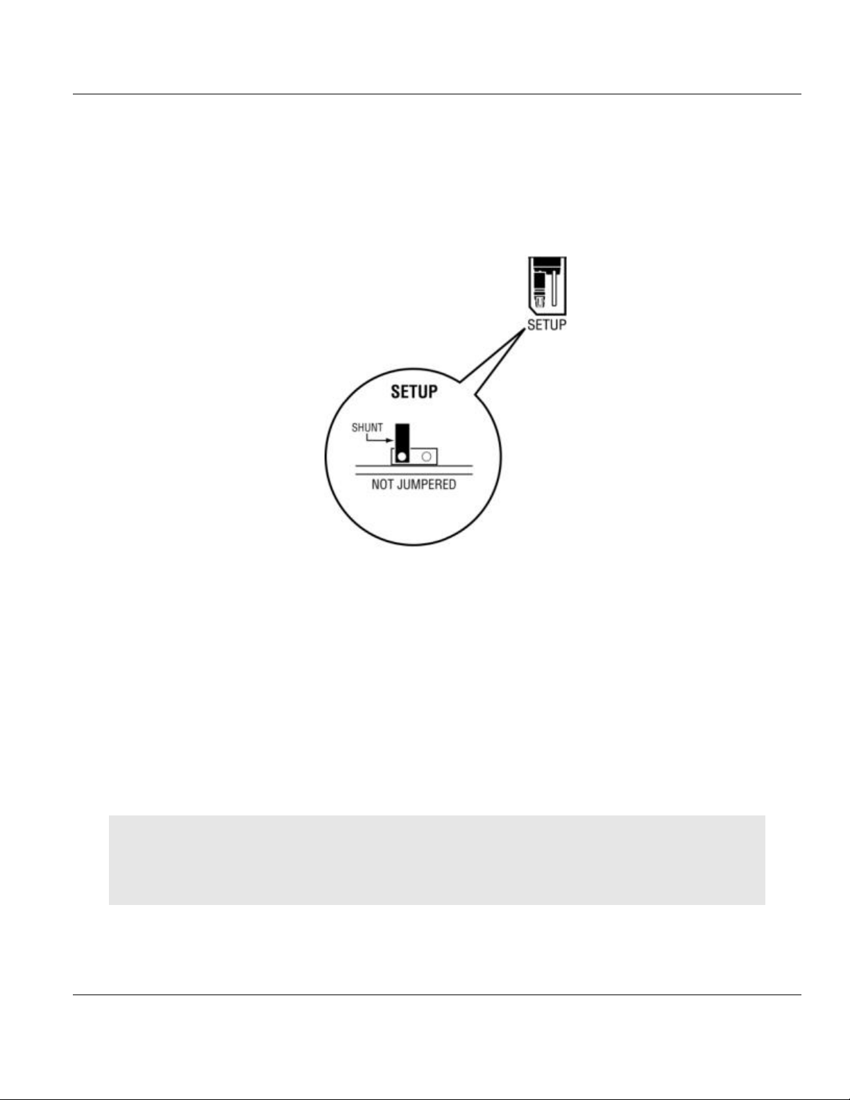
1.4.1 Setup Jumper
The Setup Jumper acts a write protection for the module's firmware. In "write-protected"
mode, the setup pins are not connected which prevents the module's firmware from being
overwritten.
The module is shipped with the Setup Jumper OFF. If you need to update the firmware or
run a module rescue (recovery), apply the setup shunt over both pins.
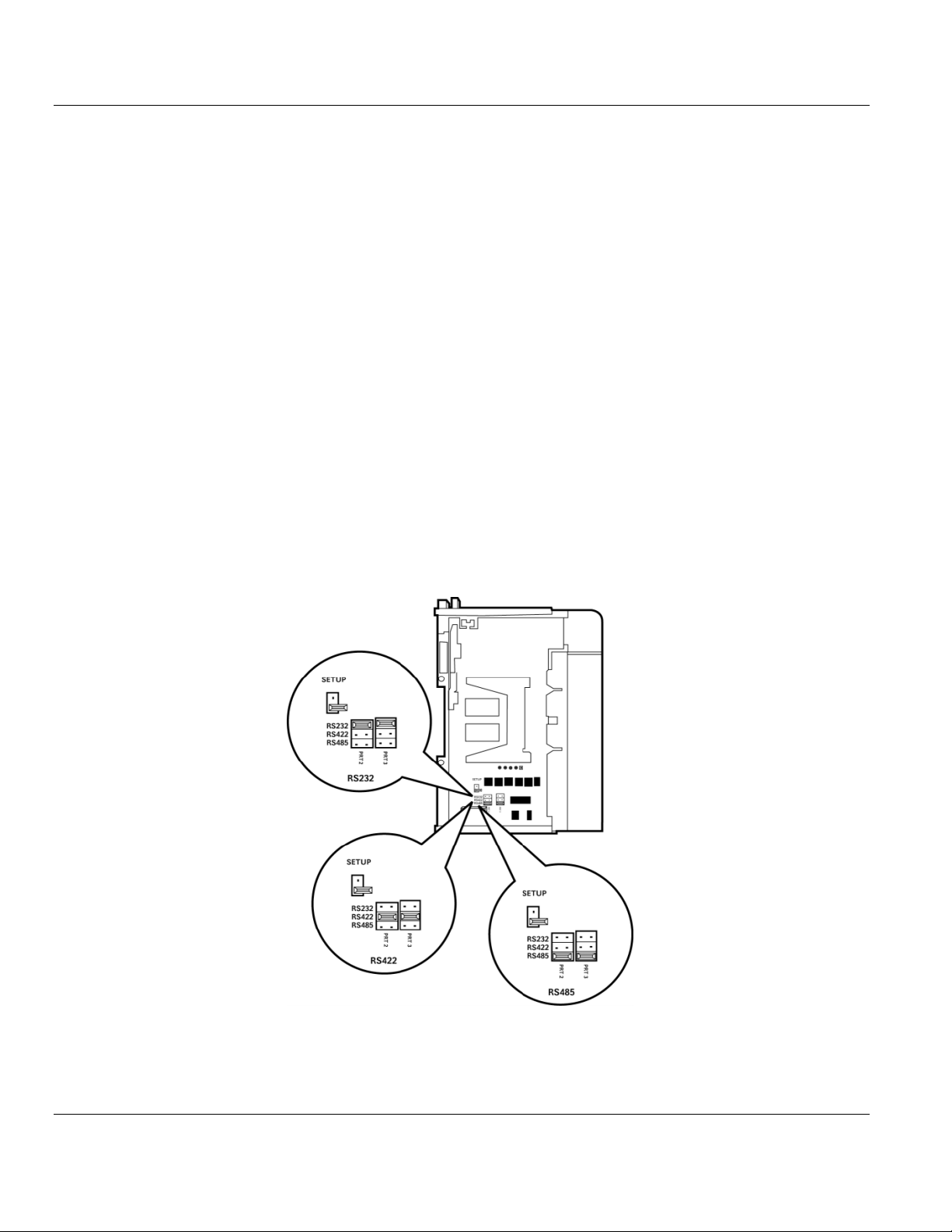
1.4.2 Port 1 and Port 2 Jumpers
These jumpers, located at the bottom of the module, aid in configuring the port settings to
RS-232, RS-422, or RS-485. The "RS-232", "RS-485", and "RS-422" labels are there for
convenience. The jumpers simply send a high/low signal when jumped or not jumped. The
jumper configuration is read by the API, and the application code must change the
appropriate port settings to the required mode (232, 485, 422).
1.5 Installing and Connecting the Module
If you have not already done so, please install and configure your CompactLogix processor
and power supply. Refer to the Rockwell Automation product documentation for installation
instructions.
Warning: You must follow all safety instructions when installing this or any other electronic devices. Failure to
follow safety procedures could result in damage to hardware or data, or even serious injury or death to
personnel. Refer to the documentation for each device you plan to connect to verify that suitable safety
procedures are in place before installing or servicing this device.
After verifying proper jumper placement, insert the module into the CompactLogix chassis.
Use the same technique recommended by Rockwell Automation to remove and install
CompactLogix modules.
Page 12 of 130 ProSoft Technology, Inc.
August 21, 2014
Page 13
MVI69E-LDM ♦ "C" Programmable Contents
Linux Application Development Module Developer's Manual
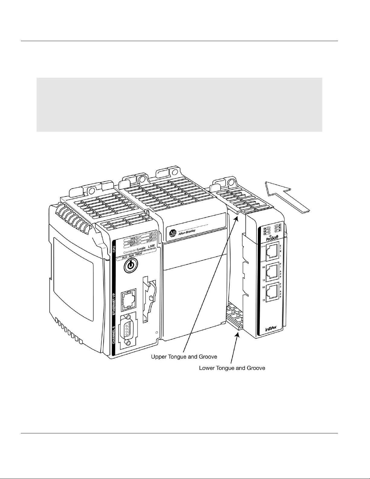
1.5.1 Installing the Module in the Chassis
You can install or remove CompactLogix system components while chassis power is applied
and the system is operating. However, please note the following warning.
Warning: When you insert or remove the module while backplane power is on, an electrical arc can cause
personal injury or property damage by sending an erroneous signal to your system's actuators. This can cause
unintended machine motion or loss of process control. Electrical arcs may also cause an explosion they occur in
a hazardous environment. Verify that power is removed, or that the area is non-hazardous before proceeding.
Repeated electrical arcing causes excessive wear to contacts on both the module and its mating connector.
Worn contacts may create electrical resistance that can affect module operation.
1 Align the module using the upper and lower tongue-and_groove slots with the adjacent
module and slide forward in the direction of the arrow.
ProSoft Technology, Inc. Page 13 of 130
August 21, 2014
Page 14
Contents MVI69E-LDM ♦ "C" Programmable
Developer's Manual Linux Application Development Module
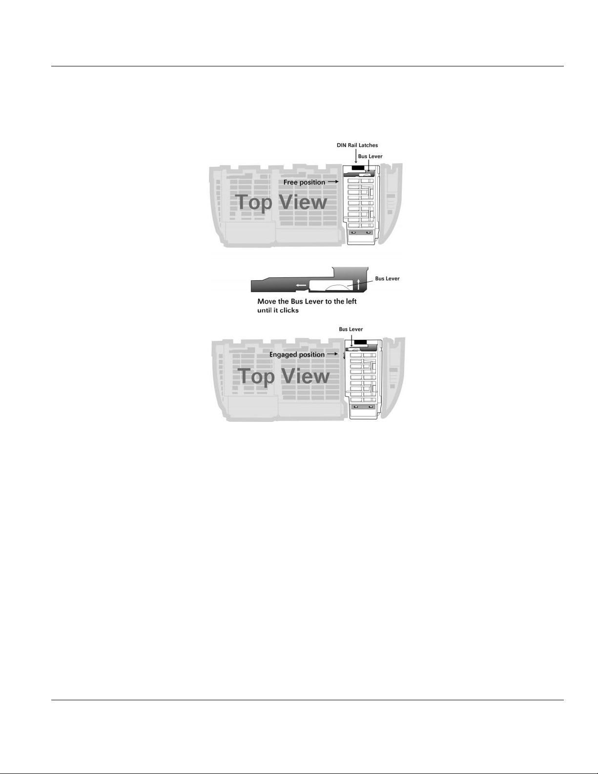
2 Move the module back along the tongue-and-groove slots until the bus connectors on
the MVI69E module and the adjacent module line up with each other. Push the module's
bus lever back slightly to clear the positioning tab and move it firmly to the left until it
clicks. Ensure that it is locked firmly into place.
3 Close all DIN-rail latches.
Page 14 of 130 ProSoft Technology, Inc.
August 21, 2014
Page 15
MVI69E-LDM ♦ "C" Programmable Contents
Linux Application Development Module Developer's Manual
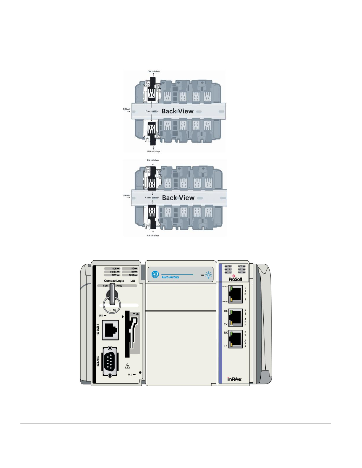
4 Press the DIN-rail mounting area of the controller against the DIN-rail. The latches
momentarily open and lock into place.
Module inserted.
ProSoft Technology, Inc. Page 15 of 130
August 21, 2014
Page 16
Contents MVI69E-LDM ♦ "C" Programmable
Developer's Manual Linux Application Development Module
1.5.2 Making Configuration Port Connections
You can communicate with the module via RS232 through the Console or through the
Ethernet port using Telnet.
RS-232 Console
You access the Console through Serial Port 1. As a default, the RS-232 Console port is
enabled. You can disable or enable this port. Refer to Enabling and Disabling the Console
Port in the next section.
1 Connect the RJ45 end of an RJ45 - DB9m cable (Cable 14) to the Serial Port 1 of the
module.
2 Connect one end of the Null Modem Cable (Cable 15) to the DB9m end Cable 14.
3 Connect the other end of Cable 15 (null modem cable) to a serial port on your PC or
laptop.
Ethernet Port
1 The module contains a Telnet client which you can access through Ethernet Port 1 (Eth
1) as shown.
2 Connect an Ethernet RJ45 cable to the Eth 1 port of the module and the other end to the
Ethernet network switch.
Page 16 of 130 ProSoft Technology, Inc.
August 21, 2014
Page 17
MVI69E-LDM ♦ "C" Programmable Contents
Linux Application Development Module Developer's Manual
To enable or disable the Telnet port:
This example uses PuTTY, which you can download for free at from:
http://www.chiark.greenend.org.uk/~sgtatham/putty/download.html
1 Start PuTTY.
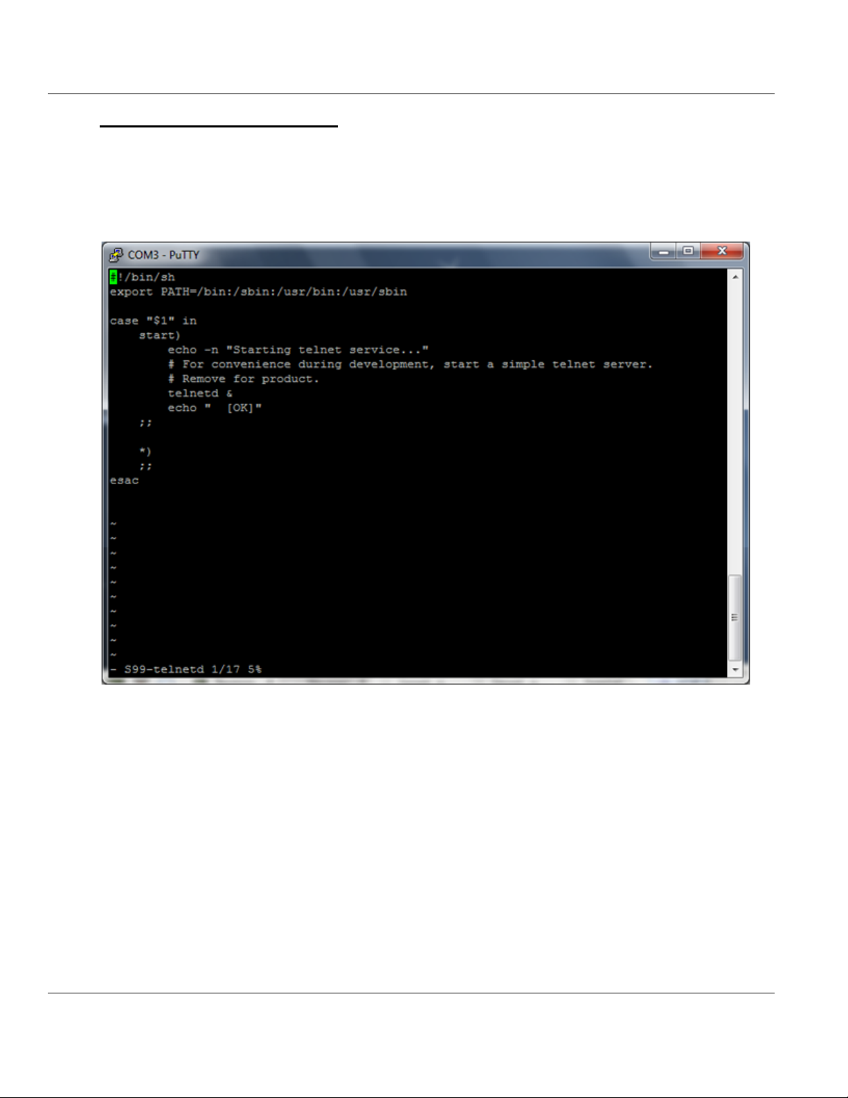
2 Open a PuTTY session as shown below. The following screenshot shows the Telnet
Port enabled.
ProSoft Technology, Inc. Page 17 of 130
August 21, 2014
Page 18
Contents MVI69E-LDM ♦ "C" Programmable
Developer's Manual Linux Application Development Module
To disable the Telnet port
1 Change to the s99-telnetd directory. Type:
cd\etc\init.d\S99-telnetd
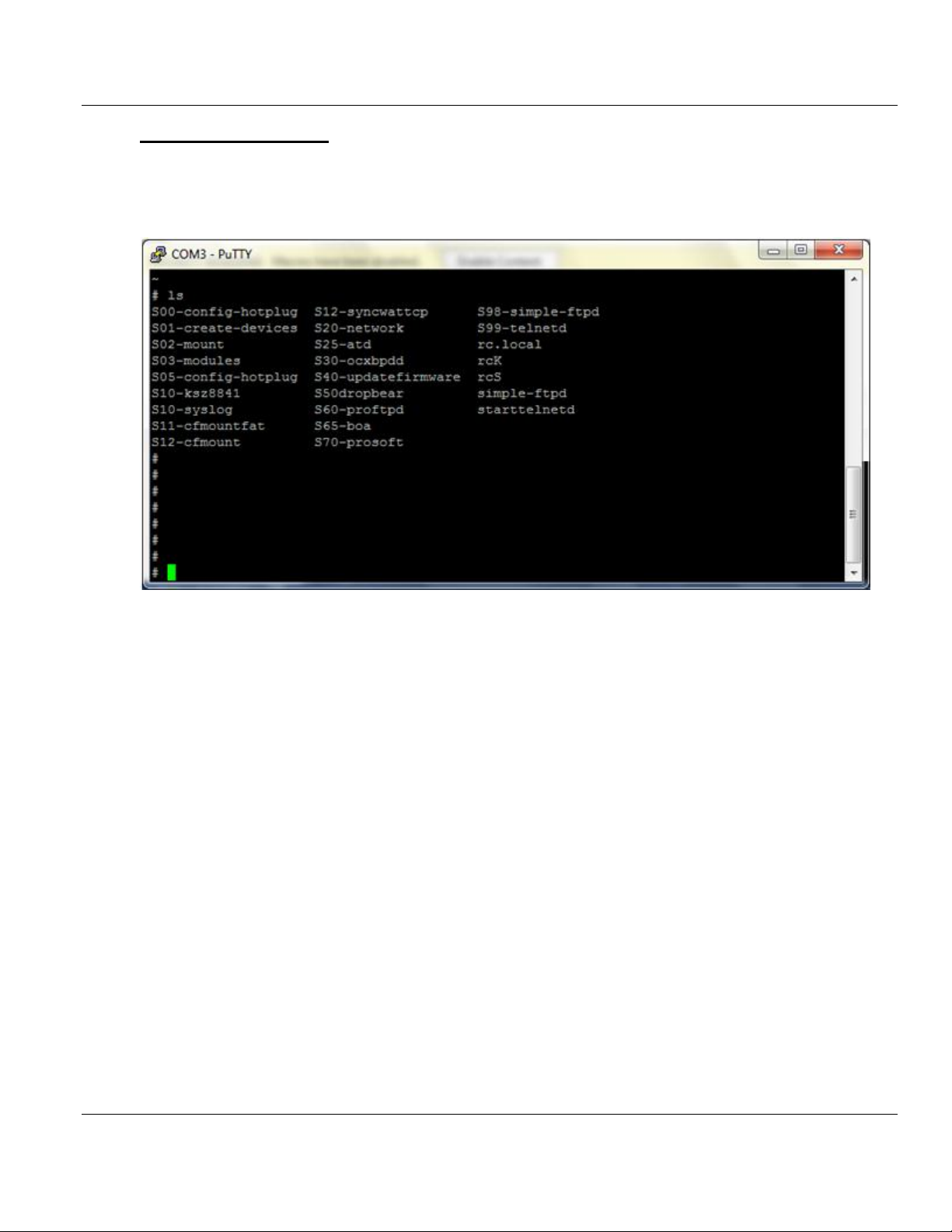
2 List the files in the directory. Type:
ls
Page 18 of 130 ProSoft Technology, Inc.
August 21, 2014
Page 19
MVI69E-LDM ♦ "C" Programmable Contents
Linux Application Development Module Developer's Manual
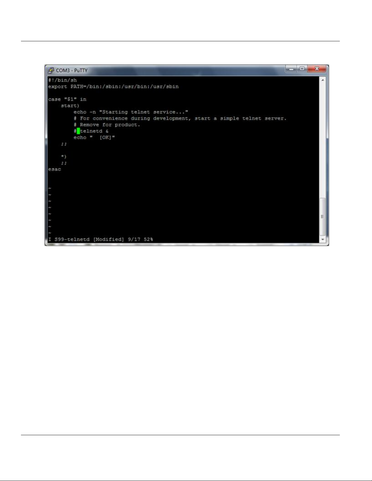
3 Comment out the telnetd file.
4 To enable the port, simply un-comment the same line.
ProSoft Technology, Inc. Page 19 of 130
August 21, 2014
Page 20
Contents MVI69E-LDM ♦ "C" Programmable
Developer's Manual Linux Application Development Module
1.5.3 Enabling and Disabling the Console Port
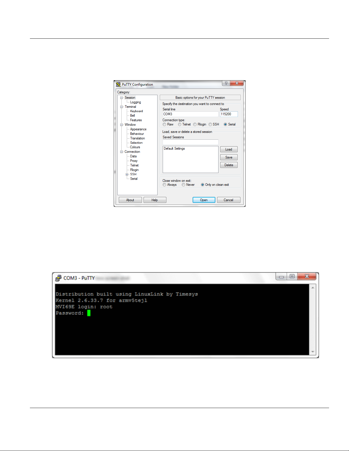
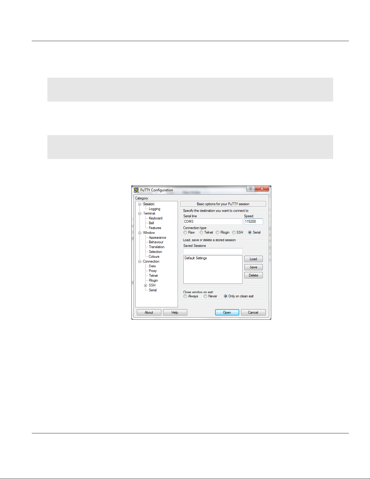
Establish a connection to the module. This example uses PuTTY.
1 Open PuTTY.
2 Set SPEED to 115200.
3 Set the SERIAL LINE to the appropriate COM port.
4 Ensure that the CONNECTION TYPE is Serial.
5 Click OPEN. The PuTTY session opens.
6 Enter your login and password.
MVI69E login: root
Password: password
Page 20 of 130 ProSoft Technology, Inc.
August 21, 2014
Page 21

MVI69E-LDM ♦ "C" Programmable Contents
Linux Application Development Module Developer's Manual
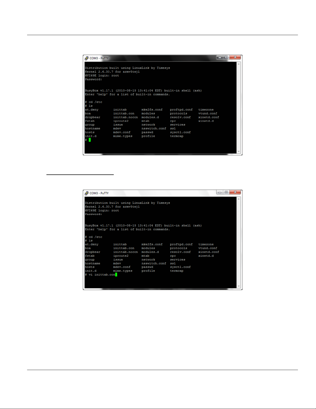
The following text appears:
7 Change to the /etc directory. Type:
cd /etc
ProSoft Technology, Inc. Page 21 of 130
August 21, 2014
Page 22
Contents MVI69E-LDM ♦ "C" Programmable
Developer's Manual Linux Application Development Module
8 Type ls. The following appears:
To enable the console port:
The inittab.con file configures the console.
Page 22 of 130 ProSoft Technology, Inc.
August 21, 2014
Page 23
MVI69E-LDM ♦ "C" Programmable Contents
Linux Application Development Module Developer's Manual
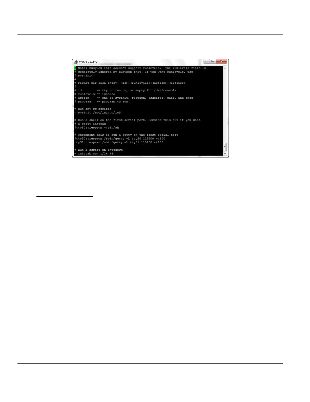
1 Open the file in the vi editor. Type
vi inittab.con
2 Copy inittab.con file to the inittab file. Type
cp –f inittab.con inittab
3 Save the file and reboot the module.
To disable the console:
1 Copy inittab.nocon file to the inittab file.
2 Save the file and reboot the module.
ProSoft Technology, Inc. Page 23 of 130
August 21, 2014
Page 24
Contents MVI69E-LDM ♦ "C" Programmable
Developer's Manual Linux Application Development Module
1.6 Establishing Module Communications
Ensure that the module is firmly seated in the rack and that the cables connected to the
module are secure. Ensure that power is applied.
Note: If you require information on cables and port pinouts, please refer to the section entitled Cable
Connections (page 91) at the end of the manual.
RS-232 Console
If you are connected to Serial Port 1 (P1), establish communications with the module using
the following procedure.
Note: The following procedure uses PuTTY to establish communications. You can use a different
communication program.
1 Open PuTTY.
2 Set SPEED to 115200.
3 Set SERIAL LINE to the appropriate COM port.
4 Ensure that CONNECTION TYPE is set to Serial.
5 Click OPEN to open the PuTTY session.
6 Enter your login and password:
MVI69E login: root
Password: password
Page 24 of 130 ProSoft Technology, Inc.
August 21, 2014
Page 25

MVI69E-LDM ♦ "C" Programmable Contents
Linux Application Development Module Developer's Manual
Ethernet (Telnet)
You can communicate with the module through Ethernet Port 1 (Eth 1) using Telnet.
The Ethernet Port (Eth 1) on the module is programmed with eth0 set to IP 192.168.0.250
and a Subnet Mask of 255.255.255.0. In order for your PC or laptop to talk to the module,
your PC or Laptop must be on the same subnet as the module. This means that you must
temporarily change the IP address and subnet mask on your PC or laptop to match that of
the module. You can then change the module's IP address to match your needs. Follow
these steps or see http://windows.microsoft.com/en-us/windows/change-tcp-ipsettings#1TC=windows-7 http://windows.microsoft.com/en-us/windows/change-tcp-ipsettings#1TC=windows-7.
1 Change the IP address of your PC or Laptop so it matches the subnet of the module.
The following steps are for Windows 7.
a Change your IP address through the router. Consult your router documentation for
more information.
b Change your IP address through Windows Network Connections. Click START >
CONTROL PANEL > NETWORK AND SHARING CENTER.
c Click the CONNECTION link for the connection you want to change and choose
PROPERTIES.
d On the Local Area Connection Properties dialog, select the connection you want to
change (Internet Protocol Version 6 or Internet Protocol Version 4), and then click
PROPERTIES.
e In the Internet Protocol Version 4 or 6 Properties dialog, click USE THE FOLLOWING IP
ADDRESS.
f Type in the IP address settings for the IP ADDRESS, SUBNET MASK, and DEFAULT
GATEWAY.
g Click OK to accept the changes and then close each of the dialog boxes.
2 Ensure that an Ethernet cable is connected to Ethernet Port 1 (Eth 1) of the module, and
the other end to the same Ethernet switch as your PC.
ProSoft Technology, Inc. Page 25 of 130
August 21, 2014
Page 26
Contents MVI69E-LDM ♦ "C" Programmable
Developer's Manual Linux Application Development Module
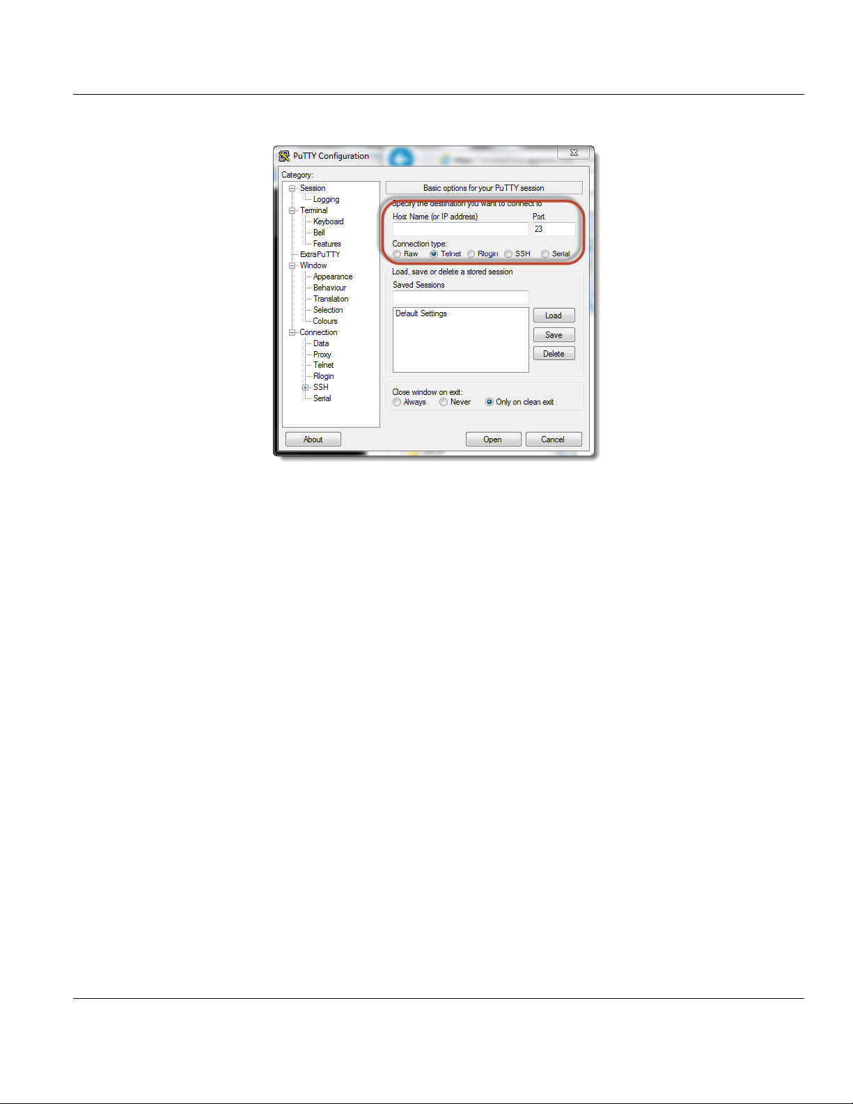
3 Use a program such as PuTTY to Telnet into the module.
4 Select Telnet as the CONNECTION TYPE.
5 Enter the IP ADDRESS (192.168.0.250).
6 Port 23 should appear as the PORT number.
7 Click OPEN to establish a connection.
8 Log into the module.
There are two methods you can use to change the module's IP address. One is temporary
for use in cases where you want to change the address long enough to make a quick
change. The other is more permanent so that the module is already programmed and is
ready for full deployment.
Temporary IP Address Change
At the Linux prompt, type:
ifconfig eth0 x.x.x.x (This changes the IP address of the Ethernet Eth 1 port.)
Permanent IP Address Change
1 At the Linux prompt, change to the /etc/network directory. Type:
cd ../etc/network
2 Open the interfaces file int he vi editor. Type:
vi interfaces
This shows the contents of the file:
iface eth0 inet static
address 192.168.0.250
network 192.168.0.0
netmask 255.255.255.0
broadcast 192.168.0.255
# gateway 192.168.0.1
Page 26 of 130 ProSoft Technology, Inc.
August 21, 2014
Page 27

MVI69E-LDM ♦ "C" Programmable Contents
Linux Application Development Module Developer's Manual
3 Using the vi editor, edit the file to change the address.
4 Save the file.
For help on using the vi editor to write and save the file, refer to
http://www.lagmonster.org/docs/vi.html
5 Change the IP address of your PC back to the original IP address and subnet.
6 Telnet to the new IP Address of the module.
1.7 Resetting the Module
In the event that it becomes necessary to revert the MVI69E-LDM module back to its initial
out-of-the-box state, there are a number of methods you can use depending on the
condition of the module.
The Rescue process re-installs all of the Operation System commands and configurations to
their original defaults. The files deleted during the rescue process are the startup scripts in
the /etc/init.d path since extra scripts in this path are automatically executed by the
operating system on startup and may cause problems. All other files may be overwritten to
the initial state of the device. Extra files are not deleted.
If the web pages and services for the module have been altered, it may not be possible to
use the web-based rescue.
To connect to the module over Ethernet:
1 Place the onboard setup jumper to the installed state. See Setup Jumper - MVI69E.
2 If you know the the IP address, change the network mask and IP of the connected PC to
compatible values.
For example, if the MVI69E-LDM is configured with the default IP address
(192.168.0.250) and network mask (255.255.255.0), the the PC should have the same
IP4 network mask and an IP address in the 192.168.0.xxx subnet.
Note that IP addresses must be unique on the network. If in doubt, create a physical
network consisting of only the MVI69E-LDM and the PC.
If you do not know the IP address of the MVI69E-LDM module, you can establish
communication through the serial configuration port, Port 1 (upper port).
1 Use Telnet or a similar terminal program to communicate with the module. The default
settings are 115,200 baud, 8 data bits,1 stop bit, No Parity, xon/xoff flow control.
2 Use the following username and password:
Username: root
Password: password
3 From the shell prompt, run ifconfig to find the Ethernet IP address and network mask of
device "eth0". Then follow the steps under To connect to the module over Ethernet
(above).
ProSoft Technology, Inc. Page 27 of 130
August 21, 2014
Page 28

Contents MVI69E-LDM ♦ "C" Programmable
Developer's Manual Linux Application Development Module
To use web-based rescue:
The web page for the MVI69E-LDM module contains a command on the left side of the page
to reset the module.
1 Open the web page for the module by entering the IP address of the module in the
address bar. If necessary, set your PC to an IP address and the same sub-network. See
To connect to the module over Ethernet (above).
2 On the left-side of the page, under FUNCTIONS, click RESCUE MODULE. Follow the
instructions to reset the module to its default state.
Note: Most loaded components are left intact by this operation so it may be necessary to make enough room on
the module for the rescue to work. In addition, the Setup Jumper must be in place for the rescue to function
properly.
To use manual rescue:
If the default web page is unavailable, a manual rescue may be required. Perform the
following steps to manually return the module to its default state:
1 Establish a terminal session to the module using either the Serial or Ethernet port.
2 Ensure that the /backup/systemrestore.tgz file exists.
3 Run the following command to remove any startup scripts that may be interfering with
the bootup process:
rm -f /etc/init.d/*
4 Restore the configuration and executables using the following command:
tar -xzf /backup/systemrestore.tgz -C /
5 If successful, reboot the module.
Page 28 of 130 ProSoft Technology, Inc.
August 21, 2014
Page 29
MVI69E-LDM ♦ "C" Programmable Contents
Linux Application Development Module Developer's Manual
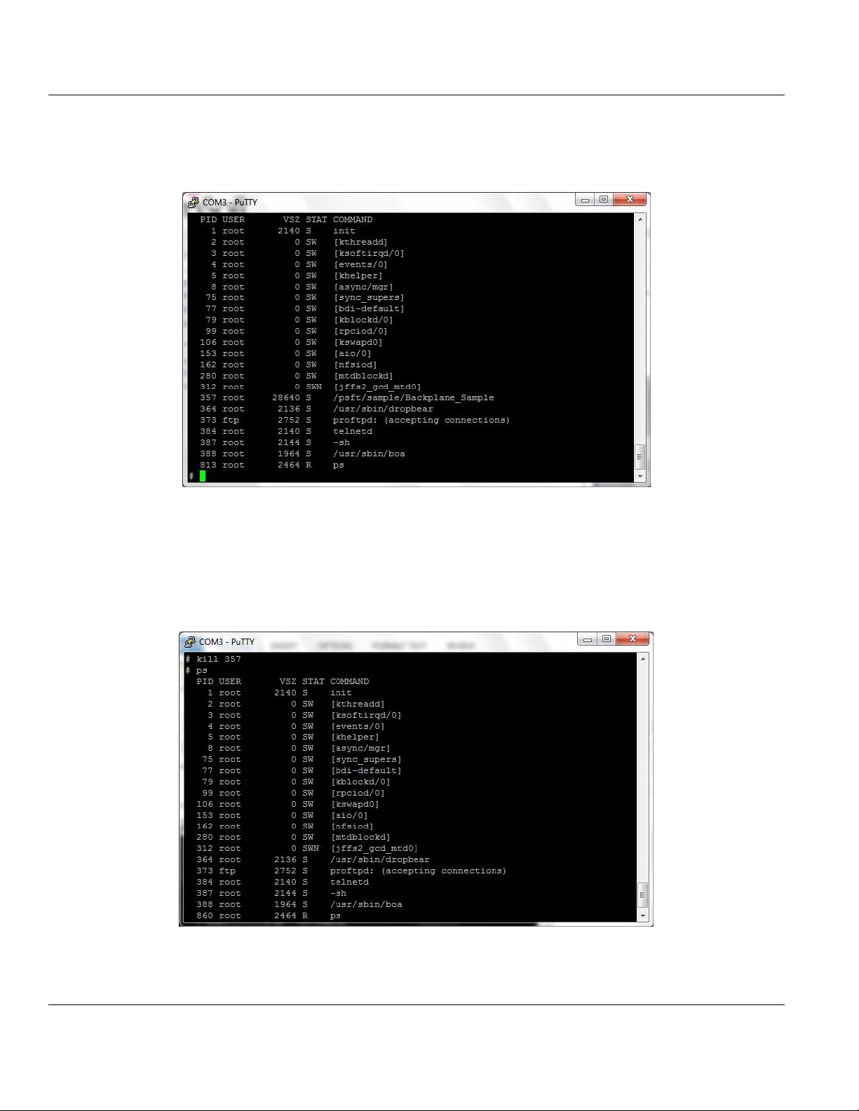
1.8 Important Information Before Development
When the MVI69E-LDM is initially installed in the backplane, the module runs a number of
programs that are required in order not to fault the processor.
Line 357, /psft/sample/Backplane_Sample runs for the purpose of not faulting the
processor. The module also contains a number of sample applications that will not run if
backplane sample is also running. The samples affected are enet_application and
serial_application.
You can kill the Backplane_Sample script by typing:
kill 357
ProSoft Technology, Inc. Page 29 of 130
August 21, 2014
Page 30
Contents MVI69E-LDM ♦ "C" Programmable
Developer's Manual Linux Application Development Module
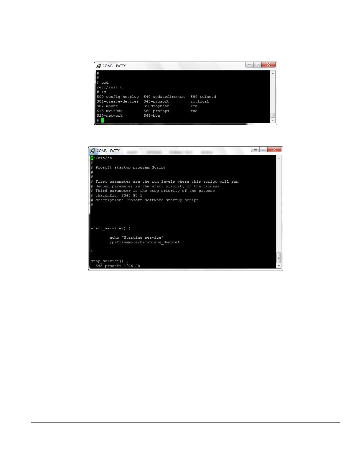
You can modify the Backplane_Sample script from this location:
The script that you want to modify is S45-prosoft.
You can see from this script that the Backplane_Sample is configured to run at startup.
Change this to suit your needs.
Page 30 of 130 ProSoft Technology, Inc.
August 21, 2014
Page 31

MVI69E-LDM ♦ "C" Programmable Contents
In This Chapter
Setup .....................................................................................................31
Starting Eclipse ......................................................................................34
Linux Application Development Module Developer's Manual
2 Development Environment
The MVI69E-LDM development tools run under Linux. In order to run these tools on a
Windows-based machine, you must run a Virtual Machine that hosts the Linux Operating
System.
VMware provides a virtual machine player used to host the Linux Operating System. You
can find it at: https://my.vmware.com/web/vmware/downloads
2.1 Setup
The file Debian6VM.zip is part of the LDMdevKit package which you can download for free
from the ProSoft Technology website: www.prosoft-technology.com/ldmdevkit. You can also
purchase the DVD (part number LDMdevKit) from ProSoft Technology.
1 Copy the Debian6VM.zip file to your PC in the VM Player image ico directory
(VMware\VMware Player\ico).
2 Uncompress Debian6VM.zip into this directory.
3 Start the VM Player by double-clicking on its icon on the Windows desktop.
4 Click OPEN A VIRTUAL MACHINE.
ProSoft Technology, Inc. Page 31 of 130
August 21, 2014
Page 32

Contents MVI69E-LDM ♦ "C" Programmable
Developer's Manual Linux Application Development Module
5 Navigate to the ico directory containing the Debian6VM file and click DEBIAN6VM.VMX.
The image file icon appears in the left window.
The following screen appears:
Page 32 of 130 ProSoft Technology, Inc.
August 21, 2014
Page 33

MVI69E-LDM ♦ "C" Programmable Contents
Linux Application Development Module Developer's Manual
6 Click PLAY VIRTUAL MACHINE. A dialog appears asking if the virtual machine has been
moved or copied. Click I COPIED IT.
7 After the image loads, the VMware Player prompts you for a username and password.
Username: user
Password: password
The home screen appears.
ProSoft Technology, Inc. Page 33 of 130
August 21, 2014
Page 34

Contents MVI69E-LDM ♦ "C" Programmable
Developer's Manual Linux Application Development Module
2.2 Starting Eclipse
Eclipse is an Integrated Development Environment (IDE) used in the Linux environment
primarily to edit source code. Full documentation and downloads are available at:
www.eclipse.org
To start Eclipse:
1 Double-click the Eclipse icon on our Windows desktop.
2 When the Workspace Launcher appears, choose the default workspace
(/home/user/workspace).
3 Click OK.
The default workspace is pre-populated with sample programs, makefiles, and scripts.
Building one of the sample projects is the recommended way to become familiar with the
environment and the build process.
2.2.1 Building a Project
Building and using a sample application consists of the following steps:
1 Compiling and linking your application.
2 Downloading the application. There are two ways you can do this:
o Use FTP transfer to download the application.
o Create a downloadable image, and then download the image to the target device
Page 34 of 130 ProSoft Technology, Inc.
August 21, 2014
(module).
Page 35

MVI69E-LDM ♦ "C" Programmable Contents
Linux Application Development Module Developer's Manual
2.2.2 Compiling and Linking
1 Start the Linux (Debian) virtual machine in the VM Player.
2 Open a Bash Shell window by clicking on the BASH SHELL icon on the main page.
3 Once in the shell, change the directory to one of the samples. In this case, change the
directory to get to the LED_sample program. Type:
cd /workspace/mvi69e-ldm/src/LDM/led_sample$
4 To recompile and link, simply type:
make
In this case, the executable is up to date and nothing needs to be done.
5 If the source is changed, the make utility detects the newer time on the source file and
rebuilds the application. The following example uses the Touch utility to cause the date
of a file (led_sample.c) to be updated as if the file had been changed, and make is reinvoked. Make detects this change, recompiles and re-links the application.
ProSoft Technology, Inc. Page 35 of 130
August 21, 2014
Page 36

Contents MVI69E-LDM ♦ "C" Programmable
Developer's Manual Linux Application Development Module
2.2.3 Downloading the Application with FTP
To transfer the application using FTP Transfer, use any FTP transfer program such as
FileZilla (https://filezilla-project.org/) from the Windows environment.
Use FileZilla to connect to the target by specifying the IP address of the MVI69E-LDM's IP.
Download the application image to the desired directory on the LDM using the FTP transfer
program.
Since Windows does not have the same detailed permissions as Linux, you must change
the file permissions on the application once in the module. Use the command chmod a+x
filename to add the execute attribute to the application.
You can also download the application by creating an image and using Firmware update.
See Creating an Application Image.
2.2.4 Creating an Application Image
An image contains all of the application-specific components required for your application.
This includes the executable(s), application-specific shared libraries, scripts, web pages,
and data files. It does not contain the operating system or common components that are
already on the target device.
The image is a compressed tar file of the application components. Once created, use the
device's web page to download the firmware upgrade. The tar file name is specified in
IMAGE CONTENTS. In the sample image, the firmware file is 'firmware/mvi69e-ldm.firmware
revision date'. This firmware file is downloaded to the directory /psfttmp on the target
device. Upon system restart, the system startup scripts unpack the tar file into the psfttmp
directory. The script /psfttmp/install is executed to move the component files into their
final destination.
A sample install file is included with the sample applications. The steps are:
1 Create all of the components that are part of the system. This mainly involves compiling
and linking executables and shared libraries.
2 Create the install script.
3 Modify any web pages and data files that will be needed.
4 Last, update the install script.
To create the Image Contents:
Each component file to be included in the image is listed in the file imagecontents in the
build directory structure for the specific application. This file contains header information
about the image and a list of entries describing the files to be added to the image. The
format of the entry is:
Add source destination file permissions
Where:
The source file is the path to the file to be included.
The destination file is the full path name of the file on the destination on the target
device.
The permissions are the Linux style permissions of the file on the destination.
Page 36 of 130 ProSoft Technology, Inc.
August 21, 2014
Page 37

MVI69E-LDM ♦ "C" Programmable Contents
Linux Application Development Module Developer's Manual
For example, a line to add the LED_Sample application looks like:
Add ../../src/ldm/led_sample/Release/Led_Sample /psft/sample/Led_Sample rwxrwxr-x
Since builds occur in /home/usr/workspace/mvi69e-ldm/build/LDM, source paths are relative
to this directory to simplify moving to a new directory.
Follow the sample provided to create a complete image contents file.
To create the Install Script:
Before creating the image, you must create and add an install script to the firmware
package. As noted above, the firmware package is downloaded into the /psfttmp directory
on the device. The install script copies the files in /psfttmp to their final destination on the
target device. You can use the install script to make backups of the current directory
contents before they are overwritten. The LDM sample install script in build/LDM/scripts
illustrates how to do this.
To create the Image:
1 In a Linux shell, change the directory to the ...build/LDM directory.
2 Run python with the following command:
python createimage.py
The python script createimage.py reads and acts on the imagecontents file and then creates
a new firmware image in the directory .../build/LDM/firmware.
Note: The script build.sh compiles and links all libs and executables and then invoke python to create the
firmware image.
2.2.5 Downloading the Image with Firmware Update
1 Ensure that the Setup Jumper is on. See Setup Jumper in this manual.
2 Navigate to the module homepage using a Web browser by entering the module's IP
address.
ProSoft Technology, Inc. Page 37 of 130
August 21, 2014
Page 38

Contents MVI69E-LDM ♦ "C" Programmable
Developer's Manual Linux Application Development Module
3 Click FIRMWARE UPGRADE. The Update page opens.
4 Click CONTINUE WITH UPDATE, and select the firmware file to be downloaded.
5 Click UPDATE FIRMWARE and wait for the module to reboot. During rebooting, the module
expands the compressed file and runs the install script to move the component files to
their final destination.
Note: The IP address reverts to the default after rebooting. This is a very common problem, so remember to
reset the IP address to the correct value. See Establishing Module Communication.
Page 38 of 130 ProSoft Technology, Inc.
August 21, 2014
Page 39

MVI69E-LDM ♦ "C" Programmable Contents
In This Chapter
API Library .............................................................................................39
MVI69E-LDM Development Tools .........................................................40
CIP API Architecture ..............................................................................40
Backplane Device Driver ........................................................................42
Linux Application Development Module Developer's Manual
3 Understanding the MVI69E-LDM API
The MVI69E LDM CPI API Suite allows software developers to access the CompactLogix
backplane without requiring detailed knowledge of the module’s hardware design. The
MVI69E-LDM API Suite consists of three distinct components; the backplane device driver,
the backplane interface engine, and the API library.
You can develop applications for the MVI69E-LDM module using industry-standard Linux
programming tools and the CPI API library. This section provides general information
pertaining to application development for the MVI69E-LDM module.
3.1 API Library
The API provides a library of function calls. The library supports any programming language
that is compatible with the 'C' calling convention. The API library is a dynamic linked library
that must be linked with the application to create the executable program>
Note: The following compiler versions are tested and known to be compatible with the MVI69E module API:
CNU C/C++ V4.4.4 for ARM9
3.1.1 Header File
A header file is provided along with the API library. This header file contains API function
declarations, data structure definitions, and constant definitions. The header file is in
standard 'C' format. Header files for the CIP API are ocxbpapi.h and ocxtagdb.h.
3.1.2 Sample Code
The sample applications illustrate the usage of the API functions. Full source for the sample
application is included, along with make files to build the sample programs.
3.1.3 CompactLogix Tag Naming Conventions
CompactLogix tags fall into two categories; controller tags and program tags.
ProSoft Technology, Inc. Page 39 of 130
August 21, 2014
Page 40

Contents MVI69E-LDM ♦ "C" Programmable
TagName
Single tag
Array[11]
Single dimensioned array element
Array[1,3]
Two dimensional array element
Array[1, 2, 3]
Three dimensional array element
Structure.Element
Structure element
StructureArray[1].Element
Single element of an array of structures
PROGRAM:MainProgram.TagName
Tag "TagName in program called "MainProgram"
PROGRAM:MainProgram.Array[11]
An array element in program "MainProgram"
PROGRAM:MainProgram.Structure.Element
A Structure Element in program "MainProgram"
Developer's Manual Linux Application Development Module
Controller Tags have global scope. To access a controller scope tag, you only need to
specify the tag controller name. For example:
Program Tags are tags declared in a program and scoped only within the program in which
they are declared. To correctly address a Program Tag, you must specify the identifier
"PROGRAM:" followed by the program name. A dot (.) separates the program name and the
tag name.
PROGRAM:ProgramName.TagName
Rules
A tag name can contain up to 40 characters.
A tag name must start with a letter or underscore ("_"). All other characters can be
letters, numbers or underscores.
Names cannot contain two contiguous underscore characters and cannot end in with an
underscore.
Letter case is not significant.
The naming conventions are based on the IEC-1131 Rules for Identifiers.
For additional information on CompactLogix CPU tag addressing, please refer to the
CompactLogix User Manual.
3.2 MVI69E-LDM Development Tools
An application that is developed for the MVI69E-LDM module must be executed from the
module’s Flash ROM disk. Tools are provided with the API to build the disk image and
download it to the module’s Config/Debug port. See Building a Project (page 34).
Page 40 of 130 ProSoft Technology, Inc.
August 21, 2014
Page 41
MVI69E-LDM ♦ "C" Programmable Contents
Linux Application Development Module Developer's Manual
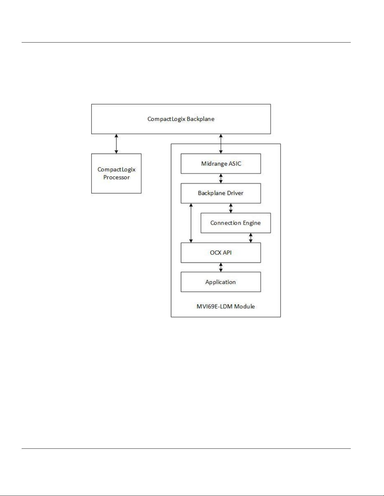
3.3 CIP API Architecture
The CIP API communicates with the CompactLogix modules through the backplane device
driver. The following illustration shows the relationship between the module application, CIP
API, and the backplane driver:
ProSoft Technology, Inc. Page 41 of 130
August 21, 2014
Page 42
Contents MVI69E-LDM ♦ "C" Programmable
Developer's Manual Linux Application Development Module
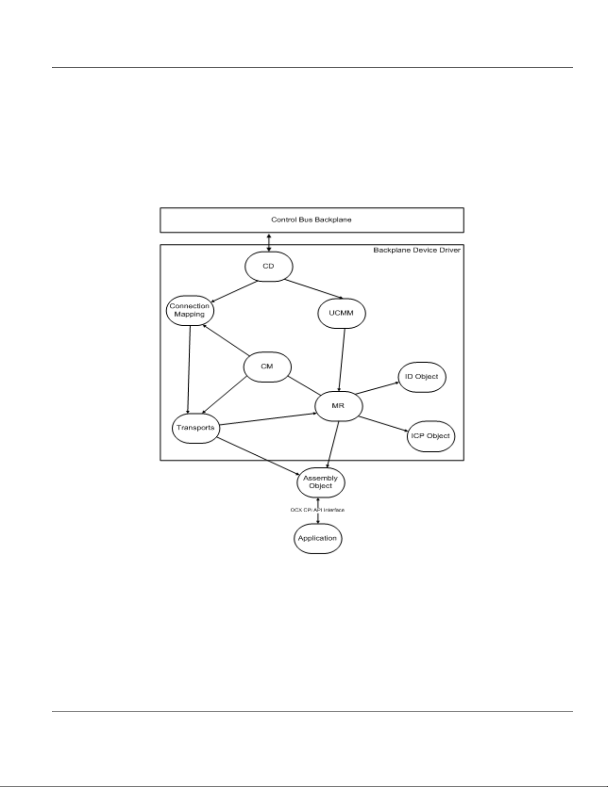
3.4 Backplane Device Driver
The backplane device driver performs CIP messaging over the CompactLogix backplane
using the Midrange ASIC. The user application interfaces with the backplane device driver
through the CIP API library. The backplane device driver for the MVI69E-LDM module is
libocxbpeng.so. The driver implements the following components and objects:
All data exchange between the application and the backplane occurs through the Assembly
Object, using functions provided by the CIP API. The API includes functions to register or
unregister the object, accept or deny Class 1 schedule connections requests, access
scheduled connection data, and service unscheduled messages.
Page 42 of 130 ProSoft Technology, Inc.
August 21, 2014
Page 43

MVI69E-LDM ♦ "C" Programmable Contents
In This Chapter
Establishing a Console Connection .......................................................44
Sample Tutorials ....................................................................................46
Application Tutorials...............................................................................52
Linux Application Development Module Developer's Manual
4 Sample Code
To help understand the use of the MVI69E-LDM module, several example programs are
provided with the module. These programs exist both as source code in the development
environment as well as executable programs in the MVI69E-LDM module in the
/psft/sample directory.
You can build and download the sample programs to the MVI69E-LDM module. The sample
programs are designed to show one or more sets of functionality.
LED Sample
Opens the backplane
Read and print module information
Read and print version information
Read and print module configuration jumpers
Continuously change the state of the front panel LEDs
Backplane Sample
Opens the backplane
Set up communications with the PLC
Read and display module information
Read and write connected data with the CompactLogix processor
Server Ethernet Sample
Opens the backplane
Listens for a request on a well known port
Responds with the date/time of the module
Client Ethernet Sample
Opens the backplane
Sends a request to another module; to the server Ethernet Sample
Prints the response to the terminal
Serial Sample
Opens the backplane
Reads and modifies the serial configuration
Transmits though the serial port
Install LDM
Sets the module identity to ProSoft LDM
Opens the backplane
Read and print module information
ProSoft Technology, Inc. Page 43 of 130
August 21, 2014
Page 44

Contents MVI69E-LDM ♦ "C" Programmable
Developer's Manual Linux Application Development Module
4.1 Establishing a Console Connection
In order to run the Ethernet and Serial samples and tutorials, you must set up a connection
in order to communicate with the MVI69E-LDM.
4.1.1 Physically Connect to the Module
In order to establish a console session between a PC and the MVI69E-LDM, you must
physically connect your PC to the console serial port on the module.
1 Plug in an RJ45 to DB9 cable on the module's Port 1.
2 Connect the null modem cable to the DB9 end of the RJ45 to DB9 cable.
3 Connect the other end of the null modem cable to the appropriate serial port (USB to
Serial Converter) on the computer.
4.1.2 Configuring Serial Communication
1 Establish a connection to the module. The following example uses PUTTY. You can
download PUTTY for free from:
http://www.chiark.greenend.org.uk/~sgtatham/PuTTY/download.html
http://www.chiark.greenend.org.uk/~sgtatham/putty/download.html
2 MVI69E login: root
Password: password
Keep PUTTY open while you set up CompactLogix as described in the next section.
Page 44 of 130 ProSoft Technology, Inc.
August 21, 2014
Page 45
MVI69E-LDM ♦ "C" Programmable Contents
Linux Application Development Module Developer's Manual
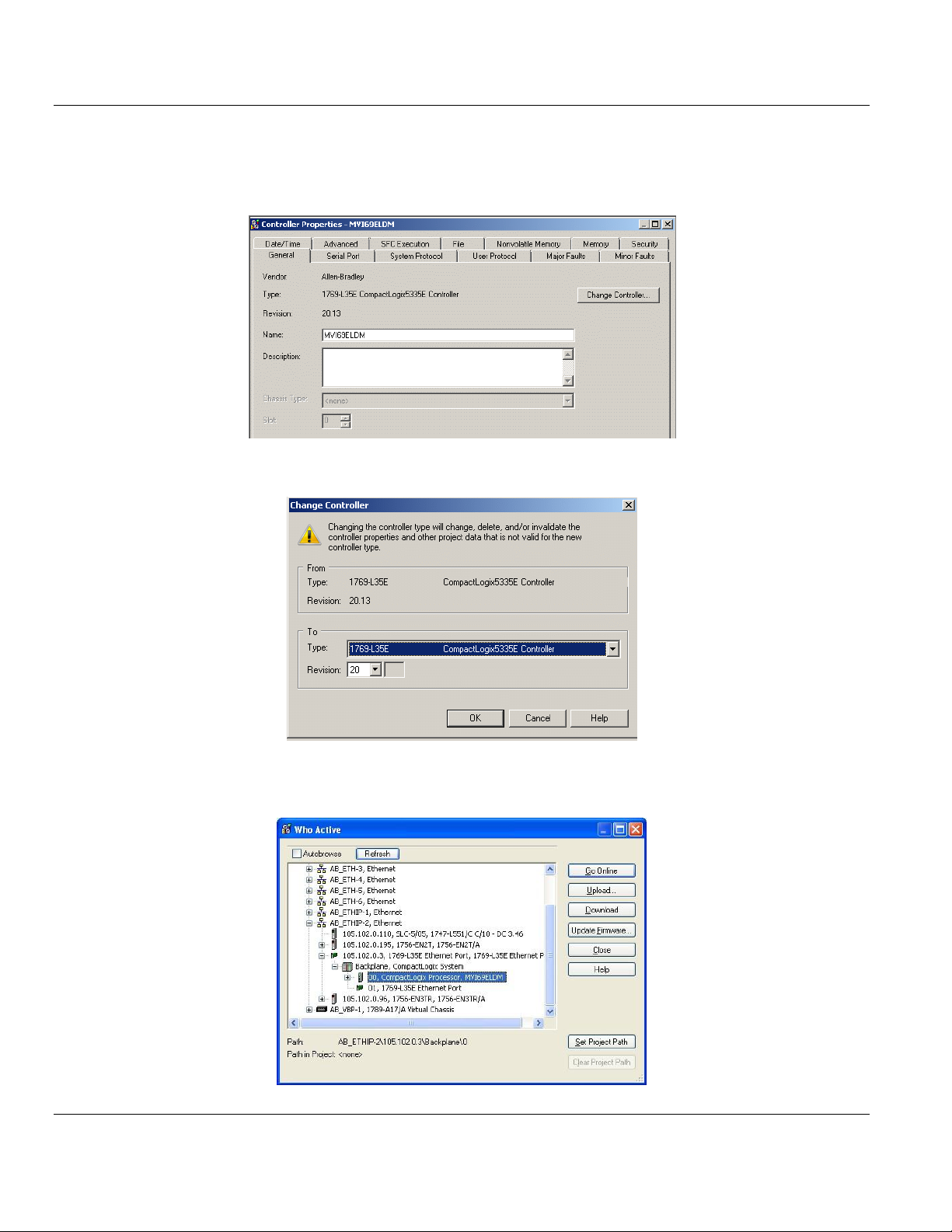
4.1.3 Setting Up ControlLogix 5000
1 Open the MVI69E-LDM.ACD program and then click CHANGE CONTROLLER to change
the appropriate chassis type to match your hardware and firmware.
2 Select the TYPE and REVISION of your Controller and click OK .
3 Download MVI69_LDM.ACD file in the CompactLogix processor by choosing
COMMUNICATIONS > WHO ACTIVE > DOWNLOAD.
ProSoft Technology, Inc. Page 45 of 130
August 21, 2014
Page 46

Contents MVI69E-LDM ♦ "C" Programmable
Developer's Manual Linux Application Development Module
4.2 Sample Tutorials
The following sections describe how to run and understand the sample tutorials provided
with the module. These samples handle the data exchange between the MVI69E-LDM and
end device(s).
4.2.1 Ethernet Sample
The Ethernet sample comes as two programs; a client, and a server.
The server waits for a client to request a connection, replies with the local time, and
closes the connection.
The client runs with the IP4 address of the server.
The client opens a connection to the server, receives the response message, and prints
the message (the time on the server) to the console.
It is recommended that you run the server on one MVI69E-LDM module and the client on
another. Alternately, either of the programs could be ported to another Linux environment.
Attempting to run both programs on the same MVI69E-LDM is not advised due to the
complexity of IP routing.
Server ENet Sample
To run the Server ENet sample:
1 Establish a command window using Telnet or similar terminal software on the PC
through the Serial P1 port.
2 Login as user: root, using password: password.
3 The Ethernet Port E1 is used to communicate with the client device. The server and
client devices must both be connected on the same IPv4 subnet.
4 Set the IPv4 address and mask of the Ethernet port using the ifconfig command.
Page 46 of 130 ProSoft Technology, Inc.
August 21, 2014
Page 47

MVI69E-LDM ♦ "C" Programmable Contents
Linux Application Development Module Developer's Manual
To execute the sample:
1 Navigate to the default home directory /psft/sample.
2 Type the command ./Server_Sample& to run the program as a background task. The
server will wait forever processing requests from clients.
While reviewing the source code, you'll see that the program:
registers sigquit_handler for four signals using the signal function.
checks command line and prints usage message if needed.
opens the backplane using open_backplane(). See the description in Backplane_Sample.
initializes the LEDs on the front panel.
Calls the function socket() to create an UN-named socket inside the kernel. socket()
returns an integer known as a socket descriptor:
o The function takes domain/family as its first argument. For Internet family of IPV4
addresses, use AF_INET.
o The second argument SOCK_STREAM specifies that type of connection to use. In this
case, a sequential, reliable, two way connection is desired.
o The third argument select the protocol. Generally, this is zero as the system normally
only has one protocol for each type of connection, although it is possible to have
multiple protocols for a connection type. Zero tells the system to use the default
protocol for the specified type of connection. In this case, the default is TCP.
zeros out the send buff and serv addr variables.
In preparation for the call to bind(), the serv_addr is then set to the well known port
address SERVER_PORT_NUMBER, and any IP address. This allows a connection to be
accepted from any IP address as long as the well known port address is specified.
calls function bind() to assign the address specified in the structure serv_addr to the
socket created by the call to socket ().
calls function listen() with second argument as '10' to specify the maximum number of
client connections that the server will queue for this listening socket.
The call to listen() makes the socket a functional listening socket.
Code enters an infinite while loop in which:
o the call to accept() puts the server to sleep, waiting for an incoming client request.
When a request is received and the three way TCP handshake is complete, accept()
wakes up and returns the socket descriptor representing the client socket.
o time() is called to read the current system time.
o snprintf() is used to put the time into the send buffer in a human readable format.
o write() is then called to send formatted time to the client.
o close() is then used to close the connection to the client.
o sleep() is invoked to yield the processor for one second.
Client ENet Sample
To run the Client ENet Sample:
1 Establish a command window using Telnet or similar terminal software on the PC
through the Serial P1 port.
2 Login as user: root, using password: password.
3 The Ethernet Port E1 will be used to communicate with the server. The server and client
devices must both be connected on the same IPv4 subnet.
4 Set the IPv4 address and mask of the first Ethernet port using ifconfig command.
ProSoft Technology, Inc. Page 47 of 130
August 21, 2014
Page 48

Contents MVI69E-LDM ♦ "C" Programmable
Developer's Manual Linux Application Development Module
To execute the sample:
1 Go to the default home directory /psft/sample.
2 Type the command ./Client_Sample ip.address.of.server to run the program. The IP
address of the server node must be provided in order for the server to know which node
is executing the server program.
3 The client will send a connection request to the server, print the response from the
server to the console, and then exit.
Reviewing the source code for Client_Sample, you will see that the main program:
registers sigquit_handler for four signals.
checks command line and print usage message if required.
opens the backplane using open_backplane(). See the detailed description in
backplane_sample.
creates a socket with a call to socket().
initializes the server address (serv_addr) structure:
o indicates that an IP4 address is going to be used with AF_INET.
o sets the destination port is the well known port SERVER_PORT_NUMBER.
o converts the string version of the server IP address to binary with inet_pton().
connect() is called to create the TCP connection to the server.
When the sockets are connected, the server sends the date and time from the server as
a message back to the clients. The client then uses the read() function to receive the
buffer of data and prints the contents to the console.
Page 48 of 130 ProSoft Technology, Inc.
August 21, 2014
Page 49

MVI69E-LDM ♦ "C" Programmable Contents
Linux Application Development Module Developer's Manual
4.2.2 Serial Sample
To run the Serial sample:
1 Establish a command window using Telnet or similar terminal software on the PC
through the Ethernet E1 port or Serial P1 port.
2 Login:
user: root
password: password
To execute the sample:
1 Navigate to the default home directory /psft/sample.
2 Type the command ./Serial_Sample ttyS1 test string in order to run the program with
ttyS1 as the output, and "test string" sent to that port.
While reviewing the source code for Serial_Sample, you'll see that the main program:
registers sigquit_handler for four signals.
checks command line and print usage message if required.
opens the backplane using open_backplane(). See the detailed description in
backplane_sample.
reads the serial configuration jumpers and ensures that both serial ports are configured
as RS232.
opens the serial port using function open_serial_port(). Examine this function:
o opens the serial device by calling open().
o reads current serial port attributes using tcgetaddr().
o configures serial port attributes. The routine uses cfsetispeed() to set the baud rate.
It then uses tcsetattr() to set the remaining attributes.
initializes the LEDs on the front panel.
enters a for loop which transmits a test string one character at a time by calling write()
and sleeping for 500 msec using usleep().
closes the serial drive connection using close().
ProSoft Technology, Inc. Page 49 of 130
August 21, 2014
Page 50

Contents MVI69E-LDM ♦ "C" Programmable
Developer's Manual Linux Application Development Module
4.2.3 LED Sample
This program shows how to interact with the MVI69E-LDM hardware at the most basic level.
To run the LED sample:
1 Establish a command window using Telnet or similar terminal software program on the
PC, through either the Ethernet or Serial P1 port.
2 Login as user: root, using password: password.
To execute the sample:
1 Navigate to the default home directory /psft/sample and type the command
./Led_Sample&. This will run the Led_Sample program in the background.
2 Looking at the sample source, you'll see that the program:
o registers Linux event handlers using the signal function.
o opens a connection to the hardware via the MVI69 library API MVI69_Open. Although
the MVI69_OpenNB routine could be used (since this sample does not communicate
across the backplane).
o reads the module information using MVI69_GetModuleInfo an displays this information
to the terminal.
o reads the version information of the MVI69 driver using MVI69_GetVersionInfo and
displays this information to the terminal.
o reads the state of the serial configuration jumpers using ShowSerialJumpers and
prints this information to the terminal.
o reads the state of the Setup Jumper using the function MVI69_GetSetupJumper and
prints this information to the console.
o initializes all LEDs to OFF.
3 The program then uses two nested loops to cycle through the LEDs and changes the
state of the LED to every possible display state. This uses the MVI69_SetLED function.
4 Exit the program by killing it (CTRL-C or kill -9).
Page 50 of 130 ProSoft Technology, Inc.
August 21, 2014
Page 51

MVI69E-LDM ♦ "C" Programmable Contents
Linux Application Development Module Developer's Manual
4.2.4 Backplane Sample
The Backplane Sample program shows block transfer communication with the
CompactLogix controller in slot 0 of the CompactLogix rack. The CompactLogix controller
must be loaded with the sample ladder logic and be configured to communicate with the
MVI69E-LDM module. The ladder is MVI69_LDMACD.
To run the Backplane sample:
1 Establish a command window using Telnet or similar terminal software on the PC
through either the Ethernet or Serial P1 port.
2 Login
user: root
password: password
To execute the sample:
1 Navigate to the default home directory /psft/sample and type the command
./Backplane_Sample& to run this program as a background task.
2 Reviewing the source code for the Backplane Sample, the program:
registers Linux event handlers using the signal function.
opens a connection to the hardware via the backplane library API using the
open_backplane routine. The open_backplane will:
o change the module information with the MVI69_SetModuleInfo routine.
o call MVI69_Open to get access to the LDM hardware and backplane.
o read the size of the configured IO using MVI69_GetIOConfig.
o read and display the module identity using MVI69_GetModuleInfo.
sets each of the front panel LEDs to a default using the MVI69_SetLED function.
enters a main (infinite loop) within this loop. The program will:
o first read the current run/program mode of the processor using MVI69_GetScanMode,
and prints the state if it has changed since the last time it was read.
o wait for an Input Scan from the CompactLogix processor using the
MVI69_WaitForInputScan function.
Note: MVI69_WaitForOutputScan could also be used.
o MVI69_GetScanCounter function is used to read the number of the scan. The scan
count modulo 5000 is used in data write (i.e., controller input data) a few lines below.
o read output data (read data for the module) from the controller using the function
MVI69_ReadOutputImage.
o If the second element has changed since the last read, the new data is copied from
the read (controller output) data to the write (controller input) data. If the data has not
changed, the data in the writer buffer is decremented. The scan count (read above)
is written to the 0th element.
o write the data back for the controller to read using the MVI69_WriteInputImage
function.
ProSoft Technology, Inc. Page 51 of 130
August 21, 2014
Page 52

Contents MVI69E-LDM ♦ "C" Programmable
Developer's Manual Linux Application Development Module
4.3 Application Tutorials
The following sections describe how to run and understand the sample applications
provided with the module. These applications handle the data exchange between the
backplane, MVI69E-LDM, and end device(s).
4.3.1 Ethernet Application
You cannot run this sample if Backplane_Sample is running. Backplane_Sample runs by
default during startup. To run the enet_application sample, you must kill the
Backplane_Sample script. See the section entitled "Important Module Startup Information -
Please Read" for information on how to kill or change the Backplane_Sample script.
The Ethernet Communications program illustrates how to interact with the MVI69E-LDM
using its Ethernet port as both a server and a client communicating through the backplane to
send and receive data. The sample also uses multi-threading in order to run as both a
server and client asynchronously.
To test the MVI69E-LDM as a client:
1 Set up TCP Stress Tester as a server with the following parameters:
o PORT: 5000
o CONNECTION: TCP
o SEND SPEED: Single
o TYPE: Server
2 Subnet Example: 10.1.3.x (or default 192.168.0.250)
3 Click OPEN and allow the TCP Stress Tester to listen once the sample program launches
(steps to launch the sample program below)..
Page 52 of 130 ProSoft Technology, Inc.
August 21, 2014
Page 53

MVI69E-LDM ♦ "C" Programmable Contents
Linux Application Development Module Developer's Manual
To test the MVI69E-LDM as a server:
1 Set up TCP Stress Tester as a client:
o PORT: 6000
o CONNECTION: TCP
o SEND SPEED: Single
o TYPE: Client
Subnet Example: 10.1.2.x (or default 192.168.1.250).
2 Ensure that you use the IP address of one of the two Ethernet ports available on the
MVI69E-LDM as the HOST address (information to access / set IP addresses in the
module is discussed later).
3 Launch the sample ladder for the MVI69E-LDM in RSLogix 5000. Please observe that
the module is not proceeding with I/O communications. This is normal. The sample
program initiates backplane communication.
4 To communicate on the MVI69E-LDM, use Telnet or other terminal connection program
to open a serial connection (baud 115200) to the COM port of choice on either of the two
computers.
To change Ethernet port IP addresses to use the subnets chosen temporarily:
1 Type in the terminal console:
ifconfig eth0 x.x.x.x where 'x' is your IP address of choice for Ethernet Port 0.
2 Navigate to the sample directory
cd /psft/sample.
3 Type command ./enet_application without the destination IP address when testing the
MVI69E-LDM as a server. Type command ./enet_application x.x.x.x where 'x' is the
destination IP address of the server running TCP Stress Tester when testing the
MVI69E-LDM as a client.
ProSoft Technology, Inc. Page 53 of 130
August 21, 2014
Page 54

Contents MVI69E-LDM ♦ "C" Programmable
Developer's Manual Linux Application Development Module
To initiate external client communication:
Click OPEN once the Ethernet Communications sample is running in RSLogix 5000 (you
may have to click twice depending on your computer).
Once the program is running and a TCP Tester server and client information is established,
data is received through the backplane and to/from the TCP Stress Testing applications and
RSLogix 5000. The program modifies the tags within RSLogix 5000 using the sample ladder
provided with any string input:
Input Tags: 0-9 can be modified by the MVI69E-LDM client for the MVI69E-LDM.
Output Tags: 0-9 can be modified by the TCP Tester server for the MVI69E-LDM.
Input Tags: 11-20 can be modified by the MVI69E-LDM server of the MVI69E-LDM.
Output Tags: 10-19 can be modified by the TCP Tester client of the MVI69E-LDM
Please note that it is recommended to set the 'Style' in RSLogix 5000 to 'ASCII' instead of
INT or Hex due to the way that RSLogix 5000 interprets bytes and byte order.
RSLogix 5000 creates a high byte and low byte for each tag in its database. For example, if
the word 'Hello!' was typed from the TCP Stress Tester, RSlogix5000 separates the values
to:
'eH'
'll'
'!o'
Since the values are read in byte order (from right most to left most), there is a high byte and
low byte used and RSLogix 5000 combines those byte values in you choose to view it as in
INT or Hex value.
For example, the letters 'te' in a single tag are separated and combined as follows:
Binary Value: 01110100 0110010
ASCII: t e
Combined Binary Value: 0111010001100101 = 29797 int
ASCII (INT Value): 101 116
Page 54 of 130 ProSoft Technology, Inc.
August 21, 2014
Page 55

MVI69E-LDM ♦ "C" Programmable Contents
Linux Application Development Module Developer's Manual
The sample application can have its sample ladder input tags modified via TCP Stress
Tester either through the external server or the client by creating any string value up to 10
tag entries long (20 characters total, including spaces):
Click START to transmit the data from the computer into the module and backplane. It is then
updated in RSLogix 5000 with the appropriate number associations.
As mentioned earlier, all character data is sent to RSLogix 5000 in sets of two per tag since
each tag is 16 bits in length and each ASCII character resides in 8 bits (one byte). All ASCII
information for each tag reads from right to left (low byte to high byte) as shown in the
following example:
MVI69E-LDM Running as a Server
ProSoft Technology, Inc. Page 55 of 130
August 21, 2014
Page 56

Contents MVI69E-LDM ♦ "C" Programmable
Developer's Manual Linux Application Development Module
Page 56 of 130 ProSoft Technology, Inc.
August 21, 2014
Page 57

MVI69E-LDM ♦ "C" Programmable Contents
Linux Application Development Module Developer's Manual
MVI69E-LDM Running as a Client
ProSoft Technology, Inc. Page 57 of 130
August 21, 2014
Page 58

Contents MVI69E-LDM ♦ "C" Programmable
Developer's Manual Linux Application Development Module
The following diagram shows the multi-threading hierarchy. All threads (excluding the main
thread) can be removed/disabled and the sample will continue to function as directed,
excluding the functionality of the removed thread and any child threads associated with it.
4.3.2 Serial Application
You cannot run this sample if Backplane_Sample is running. Backplane_Sample runs by
default during startup. To run the serial_application sample, you must kill the
Backplane_Sample script. See the section entitled "Important Module Startup Information -
Please Read" for information on how to kill or change the Backplane_Sample script.
The Serial_Application shows an example of how you can use the LDM module to
communicate to an end device to transmit/receive ASCII strings from the CompactLogix
processor through the backplane to the LDM module on the bottom serial port (default
application port). This same sample program:
Streams ASCII data into the module from the end device on the same serial port.
Sends the data to the backplane to the controller tags of the CompactLogix.
Sends out the number of bytes entered in Write_Byte_Cnt Controller tag continuously
after the Serial_App_Sample_WriteTrigger tag has been triggered from the default
application port.
Streams in ASCII data from the end device into the Controller tag Local:1:I.Data.
Page 58 of 130 ProSoft Technology, Inc.
August 21, 2014
Page 59

MVI69E-LDM ♦ "C" Programmable Contents
Linux Application Development Module Developer's Manual
To run the Serial Application sample:
Use HyperTerminal or a similar program to perform the following steps.
1 Open HyperTerminal.
2 Enter a name and choose an icon for the connection.
3 Choose the appropriate COM port.
ProSoft Technology, Inc. Page 59 of 130
August 21, 2014
Page 60
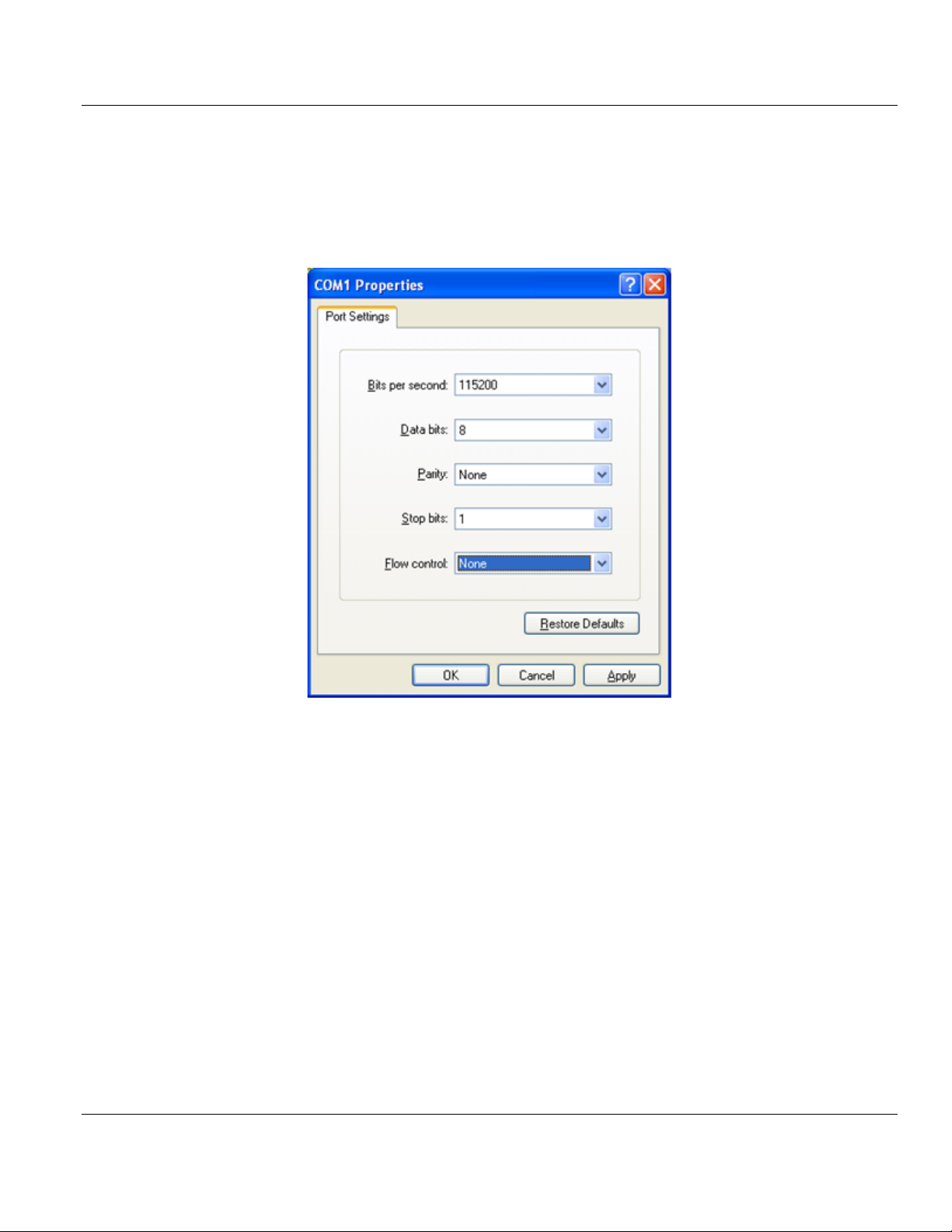
Contents MVI69E-LDM ♦ "C" Programmable
Developer's Manual Linux Application Development Module
4 Use the following settings for the Serial_Application program.
o BITS PER SECOND: 115200
o DATA BITS: 8
o PARITY: None
o STOP BITS: 1
o FLOW CONTROL: None
5 Under the ASCII SETUP, select ECHO TYPED CHARACTER LOCALLY. This allows you to see
the stream data being sent to the LDM module on the HyperTerminal screen.
Page 60 of 130 ProSoft Technology, Inc.
August 21, 2014
Page 61
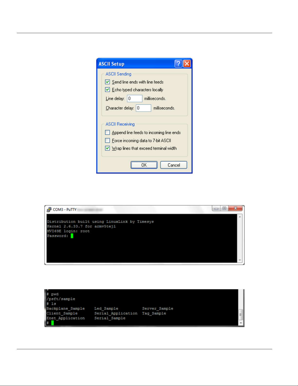
MVI69E-LDM ♦ "C" Programmable Contents
Linux Application Development Module Developer's Manual
6 Click OK, but keep HyperTerminal open since you will use it again after you complete
the following sections.
7 Use PuTTY or Telnet to log into the module.
MVI69E login: root
Password: password
8 Change to the Sample directory:
cd /psft/sample
ProSoft Technology, Inc. Page 61 of 130
August 21, 2014
Page 62

Contents MVI69E-LDM ♦ "C" Programmable
Developer's Manual Linux Application Development Module
9 Type ./ and the name of the sample program that you want to run. In this example, type:
./Serial_Application&
10 Keep PuTTY or Telnet open and set up the CompactLogix 5000 program as described in
Setting Up the ControlLogix 5000.
Page 62 of 130 ProSoft Technology, Inc.
August 21, 2014
Page 63

MVI69E-LDM ♦ "C" Programmable Contents
Linux Application Development Module Developer's Manual
11 Open the MVI69E-LDM.ACD program and change the appropriate chassis type to match
your hardware and firmware.
12 Download the MVI69E-LDM.ACD file in the CompactLogix processor by choosing
COMMUNICATIONS > WHO ACTIVE > DOWNLOAD.
ProSoft Technology, Inc. Page 63 of 130
August 21, 2014
Page 64
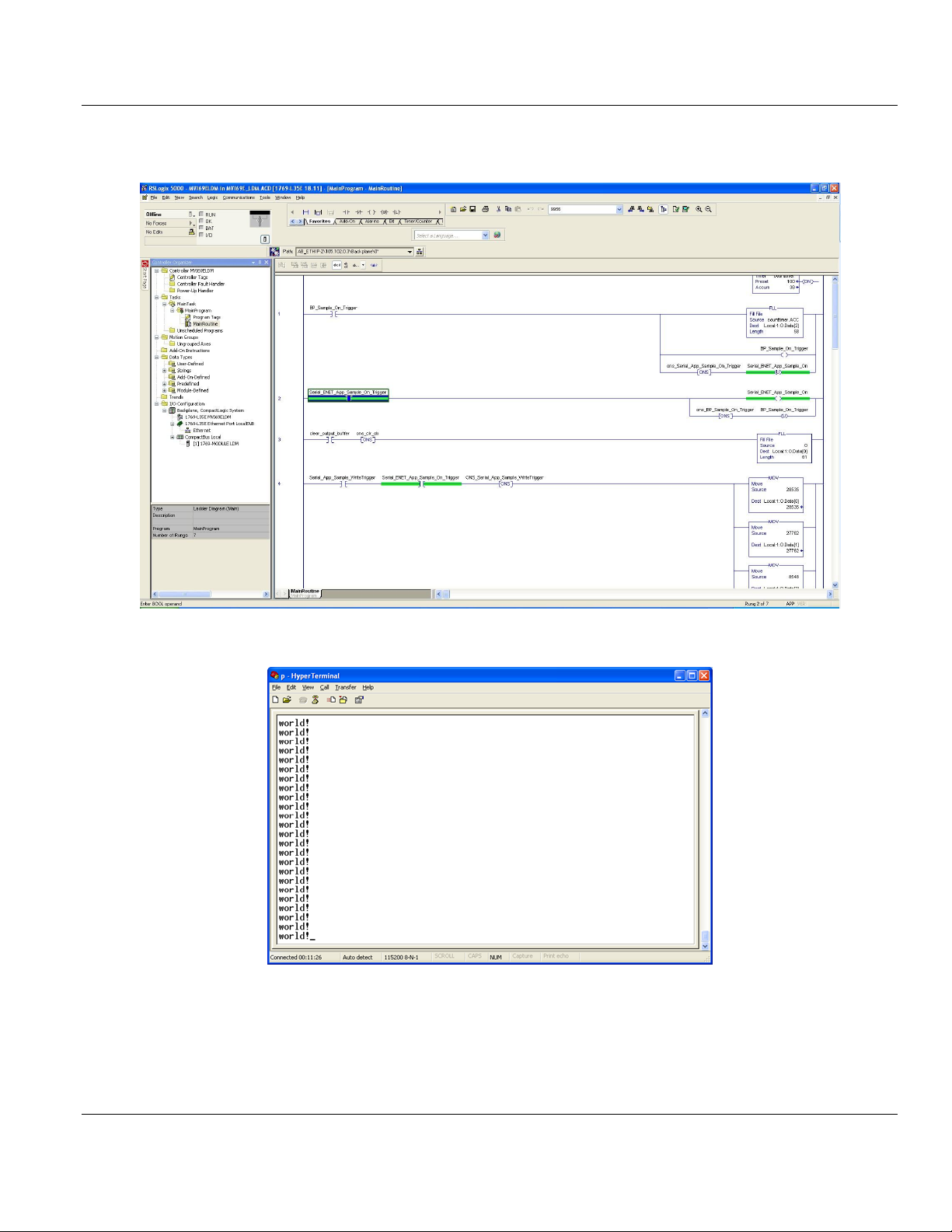
Contents MVI69E-LDM ♦ "C" Programmable
Developer's Manual Linux Application Development Module
13 Trigger 'Serial_ENET_App_Sample_On_Trigger' by right-clicking the Controller tag and
choosing TOGGLE BIT.
This causes the MVI69E-LDM module to send out the text world! to the console.
Page 64 of 130 ProSoft Technology, Inc.
August 21, 2014
Page 65

MVI69E-LDM ♦ "C" Programmable Contents
Linux Application Development Module Developer's Manual
14 You can view how the stream of data is accepted by the LDM module by untoggling the
Serial_App_Sample_WriteTrigger and typing a string of characters on the console.
ProSoft Technology, Inc. Page 65 of 130
August 21, 2014
Page 66

Contents MVI69E-LDM ♦ "C" Programmable
Developer's Manual Linux Application Development Module
15 You can see the letter 'h' in the location 'Local:1:I.Data'. Make sure that the STYLE
column in the CompactLogix is set to ASCII.
16 You can also observe this on the console port as well.
Page 66 of 130 ProSoft Technology, Inc.
August 21, 2014
Page 67

MVI69E-LDM ♦ "C" Programmable Contents
In This Chapter
CIP API Initialization Functions ..............................................................68
Direct I/O Access ...................................................................................73
Messaging .............................................................................................75
Synchronization .....................................................................................79
Serial Ports ............................................................................................81
Miscellaneous Functions ........................................................................84
Linux Application Development Module Developer's Manual
5 API Functions
ProSoft Technology, Inc. Page 67 of 130
August 21, 2014
Page 68

Contents MVI69E-LDM ♦ "C" Programmable
handle
pointer to variable of type MVI69HANDLE
MVI69_SUCCESS
API was opened successfully
MVI69_ERR_REOPEN
API is already open
MVI69_ERR_NODEVICE
backplane driver could not be accessed
Developer's Manual Linux Application Development Module
5.1 CIP API Initialization Functions
MVI69_Open
Syntax
int MVI69_Open(MVI69HANDLE *handle);
Parameters
Description
MVI69_Open acquires access to the API and sets handle to a unique ID that the application
uses in subsequent functions. This function must be called before any of the other API
functions can be used (with the exception of MVI69_SetModuleInfo).
The function provides full access to the backplane and all of the API functions. Only one
program is allowed to call this function.
IMPORTANT: Once the API has been opened, MVI69_Close should always be called before exiting the
application.
Return Value
Note: MVI69_ERR_NODEVICE will be returned if the backplane device driver is not loaded.
Example
MVI69HANDLE Handle;
if (MVI69_Open(&Handle)!= MVI69_SUCCESS)
{
printf ("Open failed!\n");
}
else
{
printf ("Open succeeded\n");
}
See Also
MVI69_Close
MVI69_OpenNB
Page 68 of 130 ProSoft Technology, Inc.
August 21, 2014
Page 69

MVI69E-LDM ♦ "C" Programmable Contents
Handle
pointer to variable of type MVI69HANDLE
MVI69_SUCCESS
API was opened successfully
MVI69_ERR_REOPEN
API is already open
MVI69_ERR_NODEVICE
Backplane driver could not be accessed.
Linux Application Development Module Developer's Manual
MVI69_OpenNB
Syntax
int MVI69_OpenNB(MVI69HANDLE *handle);
Parameters
Description
MVI69_OpenNB acquires access to the API and sets Handle to a unique ID that the application
uses in subsequent functions. This function must be called before any of the other API
functions can be used.
The purpose of this function is to provide access to certain API functions even if the API is
already in use by another program. This function does not provide access to the backplane;
however, it does provide access to the following functions.
MVI69_GetModuleInfo
MVI69_GetSerialConfig
MVI69_SetSerialConfig
MVI69_GetSetupJumper
MVI69_SetLED
MVI69_GetVersionInfo
IMPORTANT: Once the API has been opened, MVI69_Close should always be called before exiting the
application.
Return Value
Note: MVI69_ERR_NODEVICE is returned if the backplane device driver is not loaded.
Example:
MVI69Handle Handle;
if ( MVI69_OpenNB(&handle)!=MVI69_SUCCESS) {
printf ("Open failed!\n");
} else {
printf ("Open succeeded\n");
}
See Also
MVI69_Open
MVI69_Close
ProSoft Technology, Inc. Page 69 of 130
August 21, 2014
Page 70

Contents MVI69E-LDM ♦ "C" Programmable
handle
handle returned by previous call to MVI69_Open or
MVI69_OpenNB
MVI69_SUCCESS
API was closed successfully
MVI69_ERR_NOACCESS
handle does not have access
Developer's Manual Linux Application Development Module
MVI69_Close
Syntax
int MVI69_Close(MVI69HANDLE handle);
Parameters
Description
This function is used by an application to release control of the API.
handle must be a valid handle returned from MVI69_Open or MVI69_OpenNB.
IMPORTANT: Once the API has been opened, this function should always be called before exiting the
application.
Return Value
Example
MVI69HANDLE handle;
MVI69_Close (handle);
See Also
MVI69_OpenNB
MVI69_Open
After the CIP API has been opened, this function should always be called before exiting the
application.
Page 70 of 130 ProSoft Technology, Inc.
August 21, 2014
Page 71

MVI69E-LDM ♦ "C" Programmable Contents
handle
handle returned by previous call to MVI69_Open
ioconfig
Pointer to MVI69IOCONFIG structure to receive configuration
information.
MVI69_SUCCESS
no errors were encountered
MVI69_ERR_NOACCESS
handle does not have access
Linux Application Development Module Developer's Manual
MVI69_GetIOConfig
Syntax
int MVI69_GetIOConfig(MVI69HANDLE apihandle,
MVI69_IOCONFIG *ioconfig);
Parameters
Description
This function is used to obtain the IO configuration of the MVI69E module. handle must be a
valid handle returned from MVI69_Open.
The MVI69IOCONFIG structure is defined as shown:
typedef struct tagMVI69IOCONFIG
{
WORD MappedInputWords;//Input words available for direct access
WORD MappedOutputWords;//Output words available for direct access.
WORD MsgRcvBufSize;//Max size in words for received messages.
WORD MsgSndBufSize;//Max size in words for sent messages.
} MVI69IOCONFIG;
The maximum sizes in words of the module's input images are returned in the
MVI69IOCONFIG structure pointed to by ioconfig. The MappedInputWords and
MappedOutputWords members are set equal to the number of words of the respective
image that is available for direct access via the MVI69_WriteInputImage or
MVIbpReadOutputImage functions. The MsgRcvBufSize and MSgSndBufSize members
indicate the maximum size in words for received or sent messages respectively..
Return Value
Example
MVI69HANDLE handle;
MVI69IOCONFIG ioconfig;
MVI69_GetIOConfig (handle, &ioconfig);
printf ("%d words of input image available\n", ioconfig.DirectInputSize);
printf ("%d words of output image available\n", ioconfig.DirectOutputSize);
See Also
MVI69_SetIOConfig
ProSoft Technology, Inc. Page 71 of 130
August 21, 2014
Page 72

Contents MVI69E-LDM ♦ "C" Programmable
handle
handle returned by previous call to MVI69_Open
ioconfig
Pointer to MVI69IOCONFIG structure to receive configuration
information.
MVI69_SUCCESS
no errors were encountered
MVI69_ERR_NOACCESS
handle does not have access
MVI69_ERR_BADCONFIG
Configuration is not valid
Developer's Manual Linux Application Development Module
MVI69_SetIOConfig
Syntax
int MVI69_SetIOConfig(MVI69HANDLE apihandle,
MVI69_IOCONFIG *ioconfig);
Parameters
Description
This function may be used to set the size of the module's IO images available for direct IO
access. handle must be a valid handle returned from MVI69_Open.
The actual number of input and output words that are transferred between the controller and
the MVI69E module is determined by the configuration of the generic profile. The only
purpose of this routine is to set maximum sizes allowed by the MVI69_ReadOutputImage
and MVI69_WriteInputImage functions.
The message buffer sizes are fixed. Therefore, the MsgRcvBufSize and MsgSndBufSize
members are ignored by this function.
Return Value
Example
MVI69HANDLE handle;
MVI69IOCONFIG ioconfig;
ioconfig.DirectInputSize = 20; //20words used for input
ioconfig.DirectOutputSize = 10; //10 words used for output
if (MVI69_SUCCESS !=MVI69_SetIOConfig (handle, &ioconfig))
printf ("Error: IO COnfiguration failed\n");
See Also
MVI69_GetIOConfig
Page 72 of 130 ProSoft Technology, Inc.
August 21, 2014
Page 73

MVI69E-LDM ♦ "C" Programmable Contents
handle
handle returned by previous call toMVI69_Open
offset
word offset into output image at which to begin reading
length
number of words to read
buffer
pointer to buffer to receive data from output image
MVI69_SUCCESS
data was read from the output image successfully
MVI69_ERR_NOACCESS
handle does not have access
MVI69_ERR_BADPARAM
Parameter contains invalid value
Linux Application Development Module Developer's Manual
5.2 Direct I/O Access
MVI69_ReadOutputImage
Syntax
int MVI69_ReadOutputImage (MVI69HANDLE handle,
WORD offset,
WORD length,
WORD *buffer);
Parameters
Description
MVI69_ReadOutputImage reads from the module's output image.
handle must be a valid handle returned from MVI69_Open.
buffer must point to a buffer of at least length words in size.
offset specifies the word in the output image to begin reading, and length specifies the
number of words to read. The error MVI69_ERR_BADPARAM will be returned if an attempts
is made to access the output image beyond the range configured for direct IO. See the
MVI69_GetIOConfig and MVI69_SetIOConfig functions for more information.
The output image is written by the control processor and read by the module.
Return Value
Example
MVI69HANDLE handle;
WORD buffer[8];
int rc;
/* Read 8 words of data from the output image, starting with word 2*/
rc = MVI69_ReadOutputImage (Handle, 2, 8, buffer);
if (rc != MVI69_SUCCESS)
printf("ERROR: MVI69_ReadOutputImage failed");
See Also
MVI69_GetIOConfig
MVI69_SetIOConfig
MVI69_WriteInputImage
ProSoft Technology, Inc. Page 73 of 130
August 21, 2014
Page 74

Contents MVI69E-LDM ♦ "C" Programmable
handle
handle returned by previous call to MVI69_Open
offset
word offset into output image at which to begin writing
length
number of words to write
buffer
pointer to buffer of data to be written to input image
MVI69_SUCCESS
data was written to the input image successfully
MVI69_ERR_NOACCESS
handle does not have access
MVI69_ERR_BADPARAM
Parameter contains invalid value
Developer's Manual Linux Application Development Module
MVI69_WriteInputImage
Syntax
int MVI69_WriteInputImage (MVI69HANDLE handle,
WORD offset,
WORD length,
WORD *buffer);
Parameters
Description
MVI69_WriteInputImage writes to the module's input image.
handle must be a valid handle returned from MVI69_Open.
buffer must point to a buffer of at least length words in size.
offset specifies the word in the output image to begin reading, and length specifies the
number of words to write. The error MVI69_ERR_BADPARAM will be returned if an attempt
is made to access the input image beyond the range configured for direct IO. If this error is
returned, no data will be written to the input image. See the MVI69_GetIOConfig and
MVI69_SetIOConfig functions for more information.
The input image is written by the module and read by the control processor.
Return Value
Example
MVI69HANDLE handle;
WORD buffer[2];
int rc;
/* Write 2 words of data to the input image, starting with word 0*/
rc = MVI69_WriteInputImage (Handle, buffer, 0, 2);
if (rc != MVI69_SUCCESS)
printf("ERROR: MVI69_WriteInputImage failed");
See Also
MVI69_GetIOConfig
MVI69_SetIOConfig
MVI69_ReadOutputImage
Page 74 of 130 ProSoft Technology, Inc.
August 21, 2014
Page 75

MVI69E-LDM ♦ "C" Programmable Contents
handle
handle returned by previous call to MVI69_Open
buffer
pointer to buffer to receive message data from processor
length
pointer to variable containing the maximum message length in words.
When this function is called, this should be set to the size of the indicated
buffer. Upon successful return, this variable will contain the actual
received message length.
timeout
maximum number of milliseconds to wait for message
Name
Data Type
Description
MessageId
WORD
Message ID. Used to match responses
to requests.
SizeofMessage
WORD
Size of the Message data in bytes.
Message[...]
BYTEs
CIP Message packet, starting with
Service Code. Total number of bytes is
provided in the SizeofMessage field.
Linux Application Development Module Developer's Manual
5.3 Messaging
MVI69_GetMsgRequestFromBp
Syntax
int MVI69_GetMsgRequestFromBp(MVI69HANDLE handle,
WORD *buffer,
WORD *length,
WORD reserved,
WORD timeout);
Parameters
Description
This function retrieves a message sent from the control processor.
handle must be a valid handle returned from MVI69_Open.
Upon calling this function, length should contain the maximum message size in words to be
received. buffer must point to a buffer of at least length words in size. Upon successful
return, length will contain the actual length of the message received.
If length exceeds the maximum message size specified by the value MsgRcvBufSize (see
the MVI69_GetIOConfig function), MVI69_ERR_BADPARAM will be returned.
timeout specifies the number of milliseconds that the function will wait for a message. To poll
for a message without waiting, set timeout to zero. If no message has been received,
MVI69_ERR_TIMEOUT will be returned.
If the message received from the control processor is larger than length, the message will
be truncated to length words and MVI69_ERR_MSGTOOBIG will be returned.
If the call returns MVI69_SUCCESS, buffer will contain the message in the following format:
The API does not act upon any data of the Message, nor does it monitor response timeouts.
The user application is responsible for parsing the message and generating a response.
ProSoft Technology, Inc. Page 75 of 130
August 21, 2014
Page 76

Contents MVI69E-LDM ♦ "C" Programmable
MVI69_SUCCESS
a message has been received.
MVI69_ERR_NOACCESS
handle does not have access
MVI69_ERR_TIMEOUT
the timeout occurred before a message was received
MVI69_ERR_BADPARAM
a parameter is invalid
MVI69_ERR_BADCONFIG
receive messaging is not enabled
Developer's Manual Linux Application Development Module
The API can queue up to 8 requests and they remain queued after the message is given to
the user application. The user application must generate a response in order to free the
message from the queue.
Return Value
Example
MVI69HANDLE handle;
int rc;
WORD buffer[250]
WORD length;
length = 250; //maximum message size that can be received
//wait up to 5 seconds for a message
rc = MVI69_GetMsgRequestFromBp (Handle, buffer, &length, 5000);
if (rc == MVI69_SUCCESS)
printf ("Message received. Length is %d words\n", length);
See Also
MVI69_GetIOConfig
MVI69_SendMsgResponseToBp
Page 76 of 130 ProSoft Technology, Inc.
August 21, 2014
Page 77

MVI69E-LDM ♦ "C" Programmable Contents
handle
handle returned by previous call to MVI69_Open
buffer
pointer to buffer to send to processor
length
the length in words of the message to send
timeout
maximum number of milliseconds to wait to send message
Name
Data Type
Description
MessageId
WORD
Must echo MessageID of request
SizeofMessage
WORD
Size of the Message data in bytes.
Message[...]
BYTEs
CIP Response packet, starting with
Service Response. Total number of
bytes is provided in the SizeofMessage
field.
Linux Application Development Module Developer's Manual
MVI69_SendMsgResponseToBp
Syntax
int MVI69_SendMsgResponseToBp(MVI69HANDLE handle,
WORD *buffer,
WORD *length,
WORD reserved,
WORD timeout);
Parameters
Description
This function sends a response to the control processor.
handle must be a valid handle returned from MVI69_Open.
Upon calling this function, length should contain the response size in words. buffer must
point to a buffer of at least length words in size.
If length exceeds the maximum response size specified by the value MsgSndBufSize (see
the MVI69_GetIOConfig function), MVI69_ERR_BADPARAM will be returned.
When this function is called, the buffers data must contain the message in the following
format:
The API uses the MessageId field to match responses to requests from the backplane.
Once the API matches a response to its request, the response will be forwarded to the
backplane and the original request can be released.
The API does not act upon any data of the Message.
Since the API maintains an internal queue of 8 messages, the user application must
generate responses to allow reception of more than 8 messages. If 8 requests are queued
and the API receives another request, it will be dropped.
If the SizeofMessage field is set to 0, the original request is released and no response is
sent to the backplane. This allows the user application to flush messages.
ProSoft Technology, Inc. Page 77 of 130
August 21, 2014
Page 78

Contents MVI69E-LDM ♦ "C" Programmable
MVI69_SUCCESS
a message has been received.
MVI69_ERR_NOACCESS
handle does not have access
MVI69_ERR_BADPARAM
a parameter is invalid
MVI69_ERR_BADCONFIG
send messaging is not enabled
Developer's Manual Linux Application Development Module
Return Value
Example
MVI69HANDLE handle;
int rc;
WORD buffer[250];
//wait 5 seconds for the message to be sent
rc = MVI69_SendMsgResponseToBp (Handle, buffer, 250);
if (rc == MVI69_SUCCESS)
printf ("Message sent\n");
See Also
MVI69_GetIOConfig
MVI69_GetMsgRequestFromBp
Page 78 of 130 ProSoft Technology, Inc.
August 21, 2014
Page 79

MVI69E-LDM ♦ "C" Programmable Contents
handle
handle returned by previous call to MVI69_Open
timeout
maximum number of milliseconds to wait for scan
MVI69_SUCCESS
the input scan has occurred.
MVI69_ERR_NOACCESS
handle does not have access
MVI69_ERR_TIMEOUT
the timeout expired before an input scan occurred
Linux Application Development Module Developer's Manual
5.4 Synchronization
MVI69_WaitForInputScan
Syntax
int MVI69_WaitForInputScan (MVI69HANDLE handle,
WORD timeout);
Parameters
Description
MVI69_WaitForInputScan allows an application to synchronize with the scan of the module's
input image. This function will return immediately after the input image has been read. This
function may also be used by a module application to determine if the backplane is active.
handle must be a valid handle returned from MVI69_Open. timeout specifies the number of
milliseconds that the function will wait for the input scan to occur.
Note: There is no distinction in teh MVI69E module between input and output scans. Therefore, the
MVI69_WaitForInputScan and MVI69_WaitForOutputScan functions will perform exactly the same function and
are interchangeable.
Return Value
Example
MVI69HANDLE handle;
/*wait here until input scan, 50ms timeout */
rc = MVI69_WaitForInputScan (Handle, 50);
if (rc == MVI69_ERR_TIMEOUT)
printf ("Message scan did not occur within 50 milliseconds\n");
else
printf ("Input scan has occurred\n");
See Also
MVI69_WaitForOutputScan
ProSoft Technology, Inc. Page 79 of 130
August 21, 2014
Page 80

Contents MVI69E-LDM ♦ "C" Programmable
handle
handle returned by previous call to MVI69_Open
timeout
maximum number of milliseconds to wait for scan
MVI69_SUCCESS
the output scan has occurred.
MVI69_ERR_NOACCESS
handle does not have access
MVI69_ERR_TIMEOUT
the timeout expired before an output scan occurred
Developer's Manual Linux Application Development Module
MVI69_WaitForOutputScan
Syntax
int MVI69_WaitForOutputScan (MVI69HANDLE handle,
WORD timeout);
Parameters
Description
MVI69_WaitForOutputScan allows an application to synchronize with the scan of the
module's output image. This function will return immediately after the modules output image
has been written.
handle must be a valid handle returned from MVI69_Open. timeout specifies the number of
milliseconds that the function will wait for the output scan to occur.
Note: There is no distinction in the MVI69E module between input and output scans. Therefore, the
MVI69_WaitForInputScan and MVI69_WaitForOutputScan functions will perform exactly the same function and
are interchangeable.
Return Value
Example
MVI69HANDLE handle;
int rc;
/*wait here until output scan, 50ms timeout */
rc = MVI69_WaitForOutputScan (Handle, 50);
if (rc == MVI69_ERR_TIMEOUT)
printf ("Output scan did not occur within 50 milliseconds\n");
else
printf ("Output scan has occurred\n");
See Also
MVI69_WaitForInputScan
Page 80 of 130 ProSoft Technology, Inc.
August 21, 2014
Page 81

MVI69E-LDM ♦ "C" Programmable Contents
handle
handle returned by previous call to MVI69_Open
spconfig
pointer to structure of type MVI69SPCONFIG
MVI69_SUCCESS
the configuration information was read successfully
MVI69_ERR_NOACCESS
handle does not have access
Linux Application Development Module Developer's Manual
5.5 Serial Ports
The API functions in this section can be used to access tag data withing CompactLogix
controllers. The prototypes for most of these functions and their associated data structure
definitions can be found in the header file OCXTagDb.h.
The tag access functions that include "Db" in the name are for use with a valid tag database
(see OCXcip_BuildTagDb ).
MVI69_GetSerialConfig
Syntax
int MVI69_GetSerialConfig (MVI69HANDLE handle,
MVI69SPCONFIG *spconfig);
Parameters
Description
MVI69_GetSerialConfig retrieves the state of the serial port configuration jumper for the port
specified. The information is returned in the structure spconfig.
handle must be a valid handle returned from MVI69_Open.
The MVI69SPCONFIG structure is defined as follows:
typedef struct tagMVI69SPCONFIG
{
int port_num; /* Port number (1 or 2) */
int port_cfg; /* Jumper position */
} MVI69SPCONFIG;
port_num must be set to the desired port before calling this function. Upon return, port_cfg
will be set to one of the following values:
MVI69_SERIAL_CONFIG_NONE (No jumper installed)
MVI69_SERIAL_CONFIG_RS232
MVI69_SERIAL_CONFIG_RS422
MVI69_SERIAL_CONFIG_RS485
Return Value
ProSoft Technology, Inc. Page 81 of 130
August 21, 2014
Page 82

Contents MVI69E-LDM ♦ "C" Programmable
Developer's Manual Linux Application Development Module
Example
MVI69HANDLE handle;
MVI69SPCONFIG spconfig;
/*Get jumper setting for Port 2 and verify that it is RS232*/
spconfig.port_num = 2
MVI69_GetSerialConfig (Handle, &spconfig);
if (spconfig.port_cfg != MVI69_SERIAL_CONFIG_RS232)
printf ("Port 2 is not configured for RS232");
See Also
MVI69_SetSerialConfig
Page 82 of 130 ProSoft Technology, Inc.
August 21, 2014
Page 83

MVI69E-LDM ♦ "C" Programmable Contents
handle
handle returned by previous call to MVI69_Open
spconfig
pointer to structure of type MVI69SPCONFIG
MVI69_SUCCESS
the configuration information was read successfully
MVI69_ERR_NOACCESS
handle does not have access
Linux Application Development Module Developer's Manual
MVI69_SetSerialConfig
Syntax
int MVI69_SetSerialConfig (MVI69HANDLE handle,
MVI69SPCONFIG *spconfig);
Parameters
Description
MVI69_SetSerialConfig sets the serial port configuration. This function overrides the serial
port configuration jumper setting. The port number and configuration are specified in the
structure spconfig.
handle must be a valid handle returned from MVI69_Open.
The MVI69SPCONFIG structure is defined as follows:
typedef struct tagMVI69SPCONFIG
{
int port_num; /* Port number (1 or 2) */
int port_cfg; /* Jumper position */
} MVI69SPCONFIG;
Return Value
Example
MVI69HANDLE handle;
MVI69SPCONFIG spconfig;
/* Set up port 2 for RS232*/
spconfig.port_num = 2;
spconfig.port_cfg = MVI69_SERIAL_CONFIG_RS232;
MVI69_SetSerialConfig (Handle, &spconfig);
See Also
MVI69_GetSerialConfig
ProSoft Technology, Inc. Page 83 of 130
August 21, 2014
Page 84

Contents MVI69E-LDM ♦ "C" Programmable
handle
handle returned by previous call to MVI69_Open
verinfo
pointer to structure of type MVI69VERSIONINFO
MVI69_SUCCESS
the version information was read successfully
MVI69_ERR_NOACCESS
handle does not have access
Developer's Manual Linux Application Development Module
5.6 Miscellaneous Functions
MVI69_GetVersionInfo
Syntax
int MVI69_GetVersionInfo (MVI69HANDLE handle,
MVI69VERSIONINFO *verinfo);
Parameters
Description
MVI69_GetVersionInfo retrieves the current version of the API library and the backplane
device driver. This information is returned in the structure verinfo.
handle must be a valid handle returned from MVI69_Open.
The MVI69VERSIONINFO structure is defined as follows:
typedef struct tagMVI69VERSIONINFO
{
WORD APISeries; /* API series */
WORD APIRevision; /* API revision */
WORD DDSeries; /* Device driver series */
WORD DDRevision; /* Device driver revision */
} MVI69VERSIONINFO
Return Value
Example
MVI69HANDLE handle;
MVIBPVERSIONINFO verinfo;
/* print version of API library and driver */
MVI69_GetVersionInfo (handle, &verinfo);
printf("Library Series %d, Rev %d\n", verinfo.APISeries, verinfo.APIRevision);
printf("Driver Series &d, Rev %d\n, verinfo.DDSeries, verinfo.DDRevision);
Page 84 of 130 ProSoft Technology, Inc.
August 21, 2014
Page 85

MVI69E-LDM ♦ "C" Programmable Contents
handle
handle returned by previous call to MVI69_Open
modinfo
pointer to structure of type MVI69MODULEINFO
MVI69_SUCCESS
the module information was read successfully
MVI69_ERR_NOACCESS
handle does not have access
Linux Application Development Module Developer's Manual
MVI69_GetModuleInfo
Syntax
int MVI69_GetModuleInfo (MVI69HANDLE handle,
MVI69MODULEINFO *modinfo);
Parameters
Description
MVI69_GetModuleInfo retrieves identity information for the module This information is
returned in the structure modinfo.
handle must be a valid handle returned from MVI69_Open.
The MVI69MODULEINFO structure is defined as follows:
typedef struct tagMVIBPMODULEINFO
{
WORD VendorID; /* Reserved */
WORD DeviceType; /* Reserved */
WORD ProductCode; /* Device model code */
BYTE MajorRevision; /* Device major revision */
BYTE MinorRevision; /* Device minor revision */
DWORD SerialNo; /* Serial number */
BYTE Name[32]; /* Device name (string) */
} MVI69MODULEINFO
Return Value
Example
MVI69HANDLE handle;
MVIBPMODULEINFO modinfo;
/* print module name */
MVI69_GetModuleInfo (handle, &modinfo);
printf("Name is %s\n", modinfo.Name);
See Also
MVI69_SetModuleInfo
ProSoft Technology, Inc. Page 85 of 130
August 21, 2014
Page 86

Contents MVI69E-LDM ♦ "C" Programmable
handle
not used - set to 0
modinfo
pointer to structure of type MVI69MODULEINFO
MVI69_SUCCESS
the module information was read successfully
MVI69_ERR_NOACCESS
handle does not have access
Developer's Manual Linux Application Development Module
MVI69_SetModuleInfo
Syntax
int MVI69_SetModuleInfo (MVI69HANDLE handle,
MVI69MODULEINFO *modinfo);
Parameters
Description
MVI69_SetModuleInfo allows an application to set the identity information for the module.
This function must be called before MVI69_Open. The module information is provided in the
structure modinfo. handle must be a valid handle returned from MVI69_Open.
The MVI69MODULEINFO structure is defined as follows:
typedef struct tagMVIBPMODULEINFO
{
WORD VendorID; /* Reserved */
WORD DeviceType; /* Reserved */
WORD ProductCode; /* Device model code */
BYTE MajorRevision; /* Device major revision */
BYTE MinorRevision; /* Device minor revision */
DWORD SerialNo; /* Serial number */
BYTE Name[32]; /* Device name (string) */
} MVI69MODULEINFO
The module serial number is set during manufacturing and cannot be edited.
Return Value
Example
MVI69HANDLE handle;
MVIBPMODULEINFO modinfo;
/* Setup a customized module identity */
char new_name[] = "Widget 6900";
strcpy (modinfo.Name, new_name);
modinfo.VendorID = 774;
modinfo.DeviceType = 30;
modinfo.ProductCode = 42;
modinfo.MajorRevision = 2;
modinfo.MinorRevision = 1;
MVI69_SetModuleInfo (0, &modinfo);
/* Now open the API (and initialize backplane comms with new ID) */
MVI69_Open (&Handle);
See Also
MVI69_GetModuleInfo
Page 86 of 130 ProSoft Technology, Inc.
August 21, 2014
Page 87

MVI69E-LDM ♦ "C" Programmable Contents
handle
handle returned by previous call to MVI69_Open
mode
pointer to a variable that will be updated with the current processor mode
Name
Description
MVI69_RUN_MODE
Set if processor is in Run mode.
MVI69_PROGRAM_MODE
Set if processor is in Program Mode.
MVI69_SUCCESS
no errors were encountered
MVI69_ERR_NOACCESS
handle does not have access
Linux Application Development Module Developer's Manual
MVI69_GetScanMode
Syntax
int MVI69_GetScanMode (MVI69HANDLE handle,int *mode);
Parameters
Description
This function is used to query the state of the processor.
handle must be a valid handle returned from MVI69_Open.
mode is a pointer to an integer. When this function returns, this will be set to indicate the
current processor status and shown in the following table:
Return Value
Example
MVI69HANDLE handle;
int status;
MVI69_GetProcessorStatus (handle, &status);
if (status == MVI69_RUN_MODE)
//Processor is in Run Mode
else
//Processor is not in Run Mode
ProSoft Technology, Inc. Page 87 of 130
August 21, 2014
Page 88

Contents MVI69E-LDM ♦ "C" Programmable
handle
handle returned by previous call to MVI69_Open
count
pointer to a variable that will be updated with the current scan count
MVI69_SUCCESS
no errors were encountered
MVI69_ERR_NOACCESS
handle does not have access
Developer's Manual Linux Application Development Module
MVI69_GetScanCounter
Syntax
int MVI69_GetScanCounter (MVI69HANDLE handle,DWORD *count);
Parameters
Description
This function returns the current scan counter. The scan counter is a 32-bit counter that is
incremented with each backplane scan.
handle must be a valid handle returned from MVI69_Open.
Return Value
Example
MVI69HANDLE handle;
DWORD scancount;
MVI69_GetScanCounter (handle, &scancount);
Page 88 of 130 ProSoft Technology, Inc.
August 21, 2014
Page 89

MVI69E-LDM ♦ "C" Programmable Contents
handle
handle returned by previous call to MVI69_Open
lednum
Specifies which of the user LED indicators is being addressed.
ledstate
Specifies the state to set
MVI69_SUCCESS
the LED state has been set
MVI69_ERR_NOACCESS
handle does not have access
MVI69_ERR_BADPARAM
lednum or ledstate is invalid
Linux Application Development Module Developer's Manual
MVI69_SetLED
Syntax
int MVI69_SetLED (MVI69HANDLE handle,int lednum, int ledstate);
Parameters
Description
MVI69_SetLED allows an application to set the state of the LED indicators.
handle must be a valid handle returned from MVI69_Open.
lednum must be set to MVI69_LEDID_OK, MVI69_LEDID_CFG, MVI69_LEDID_P1,
MVI69_LEDID_P2, MVI69_LEDID_BP, or MVI69_LEDID_NET.
ledstate must be set to MVI69_LED_STATE_RED, MVI69_LED_STATE_GREEN,
MVI69_LED_STATE_YELLOW, or MVI69_LED_STATE_OFF.
Return Value
Example
MVI69HANDLE handle;
/* OK LED green and NET LED yellow */
MVI69_SetLED(Handle, MVI69_LEDID_OK, MVI69_LED_STATE_GREEN);
MVI69_SetLED(Handle, MVI69_LEDID_NET, MVI69_LED_STATE_YELLOW);
ProSoft Technology, Inc. Page 89 of 130
August 21, 2014
Page 90

Contents MVI69E-LDM ♦ "C" Programmable
handle
handle returned by previous call to MVI69_Open
mode
Pointer to an integer that is set to 1 if the Setup Jumper is installed, or 0 if
the Setup Jumper is not installed.
MVI69_SUCCESS
no errors were encountered
MVI69_ERR_NOACCESS
handle does not have access
Developer's Manual Linux Application Development Module
MVI69_GetSetupJumper
Syntax
int MVI69_GetSetupJumper (MVI69HANDLE handle,int *mode);
Parameters
Description
This function is used to query the state of the Setup Jumper.
handle must be a valid handle returned from MVI69_Open.
mode is a pointer to an integer. When this function returns, mode will be set to 1 if the
module is in setup mode, or 0 if not.
If the Setup Jumper is installed, the module is considered to be in Setup Mode. If may be
useful for an application to detect Setup Mode and perform special configuration or
diagnostic functions.
Return Value
Example
MVI69HANDLE handle;
int mode;
MVI69_GetSetupMode (handle, &mode);
if (mode)
// Setup jumper is installed - perform configuration/diagnostic
else
// Not in Setup Mode - normal operation
Page 90 of 130 ProSoft Technology, Inc.
August 21, 2014
Page 91
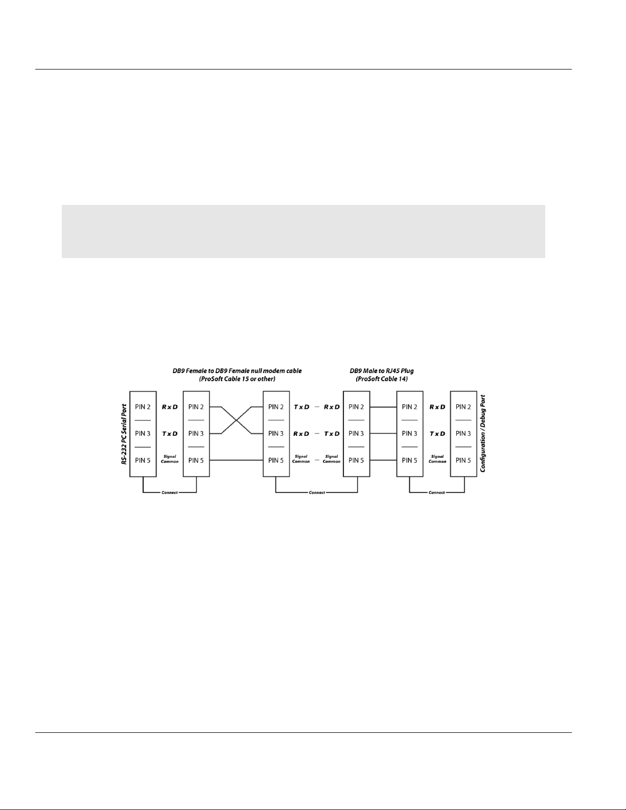
MVI69E-LDM ♦ "C" Programmable Contents
Linux Application Development Module Developer's Manual
6 Cable Connections
The application ports on the MVI69E-LDM module support RS-232, RS-422, and RS-485
interfaces. Please inspect the module to ensure that the jumpers are set correctly to
correspond with the type of interface you are using.
Note: When using RS-232 with radio modem applications, some radios or modems require hardware
handshaking (control and monitoring of modem signal lines). Enable this in the configuration of the module by
setting the UseCTS parameter to 1.
6.1 RS-232 Configuration/Debug Port
This port is physically an RJ45 connection. An RJ45 to DB-9 adapter cable is included with
the module. This port permits a PC-based terminal emulation program to view configuration
and status data in the module and to control the module. The cable pinout for
communications on this port is shown in the following diagram.
ProSoft Technology, Inc. Page 91 of 130
August 21, 2014
Page 92
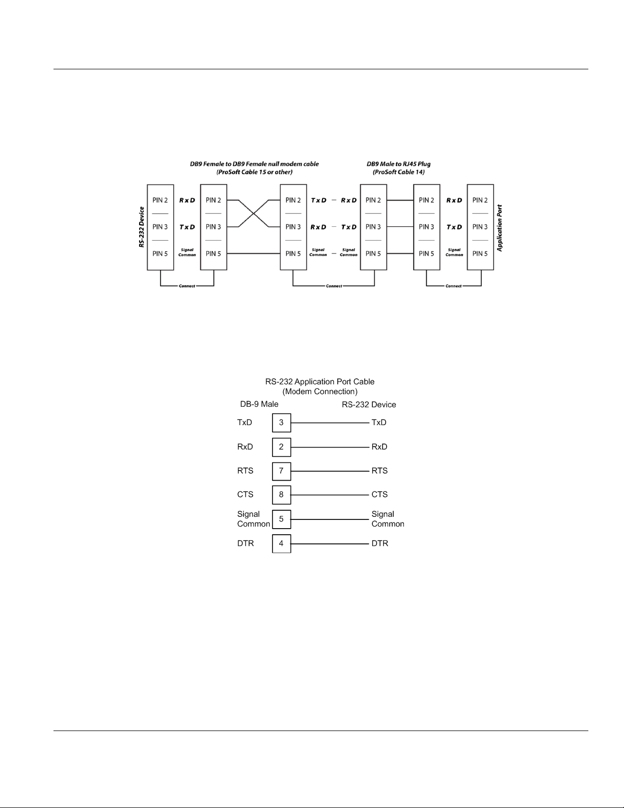
Contents MVI69E-LDM ♦ "C" Programmable
Developer's Manual Linux Application Development Module
6.2 RS-232 Application Port(s)
When the RS-232 interface is selected, the use of hardware handshaking (control and
monitoring of modem signal lines) is user definable. If no hardware handshaking will be
used, here are the cable pinouts to connect to the port.
6.2.1 RS-232: Modem Connection (Hardware Handshaking Required)
This type of connection is required between the module and a modem or other
communication device.
The Use CTS Line parameter for the port configuration should be set to Y for most modem
applications.
Page 92 of 130 ProSoft Technology, Inc.
August 21, 2014
Page 93

MVI69E-LDM ♦ "C" Programmable Contents
Linux Application Development Module Developer's Manual
6.2.2 RS-232: Null Modem Connection (Hardware Handshaking)
This type of connection is used when the device connected to the module requires hardware
handshaking (control and monitoring of modem signal lines).
6.2.3 RS-232: Null Modem Connection (No Hardware Handshaking)
This type of connection can be used to connect the module to a computer or field device
communication port.
Note: For most null modem connections where hardware handshaking is not required, the Use CTS Line
parameter should be set to N and no jumper will be required between Pins 7 (RTS) and 8 (CTS) on the
connector. If the port is configured with the Use CTS Line set to Y, then a jumper is required between the RTS
and the CTS lines on the port connection.
ProSoft Technology, Inc. Page 93 of 130
August 21, 2014
Page 94

Contents MVI69E-LDM ♦ "C" Programmable
Developer's Manual Linux Application Development Module
6.3 RS-422
The RS-422 interface requires a single four or five wire cable. The Common connection is
optional, depending on the RS-422 network devices used. The cable required for this
interface is shown below:
6.4 RS-485 Application Port(s)
The RS-485 interface requires a single two or three wire cable. The Common connection is
optional, depending on the RS-485 network devices used. The cable required for this
interface is shown below:
Page 94 of 130 ProSoft Technology, Inc.
August 21, 2014
Page 95

MVI69E-LDM ♦ "C" Programmable Contents
Linux Application Development Module Developer's Manual
Note: Terminating resistors are generally not required on the RS-485 network, unless you are experiencing
communication problems that can be attributed to signal echoes or reflections. In these cases, installing a 120ohm terminating resistor between pins 1 and 8 on the module connector end of the RS-485 line may improve
communication quality.
6.4.1 RS-485 and RS-422 Tip
If communication in the RS-422 or RS-485 mode does not work at first, despite all attempts,
try switching termination polarities. Some manufacturers interpret + and -, or A and B,
polarities differently.
6.5 DB9 to RJ45 Adaptor (Cable 14)
ProSoft Technology, Inc. Page 95 of 130
August 21, 2014
Page 96

Contents MVI69E-LDM ♦ "C" Programmable
Developer's Manual Linux Application Development Module
Page 96 of 130 ProSoft Technology, Inc.
August 21, 2014
Page 97

MVI69E-LDM ♦ "C" Programmable Contents
In This Chapter
GNU Public License ...............................................................................98
Eclipse Public License .........................................................................111
Python Public License..........................................................................115
GCC Public License .............................................................................120
Linux Application Development Module Developer's Manual
7 Open Source Licensing
This module utilizes Open Source applications, available under the GNU Public License and
others. The following sections cover all Open Source licensing:
GNU Public License
Eclipse
Python
Debian
GCC
ProSoft Technology, Inc. Page 97 of 130
August 21, 2014
Page 98

Contents MVI69E-LDM ♦ "C" Programmable
Developer's Manual Linux Application Development Module
7.1 GNU Public License
GNU GENERAL PUBLIC LICENSE
Version 3, 29 June 2007
Copyright (C) 2007 Free Software Foundation, Inc. <http://fsf.org/>
Everyone is permitted to copy and distribute verbatim copies
of this license document, but changing it is not allowed.
Preamble
The GNU General Public License is a free, copyleft license for
software and other kinds of works.
The licenses for most software and other practical works are designed
to take away your freedom to share and change the works. By contrast,
the GNU General Public License is intended to guarantee your freedom to
share and change all versions of a program--to make sure it remains free
software for all its users. We, the Free Software Foundation, use the
GNU General Public License for most of our software; it applies also to
any other work released this way by its authors. You can apply it to
your programs, too.
When we speak of free software, we are referring to freedom, not
price. Our General Public Licenses are designed to make sure that you
have the freedom to distribute copies of free software (and charge for
them if you wish), that you receive source code or can get it if you
want it, that you can change the software or use pieces of it in new
free programs, and that you know you can do these things.
To protect your rights, we need to prevent others from denying you
these rights or asking you to surrender the rights. Therefore, you have
certain responsibilities if you distribute copies of the software, or if
you modify it: responsibilities to respect the freedom of others.
For example, if you distribute copies of such a program, whether
gratis or for a fee, you must pass on to the recipients the same
freedoms that you received. You must make sure that they, too, receive
or can get the source code. And you must show them these terms so they
know their rights.
Developers that use the GNU GPL protect your rights with two steps:
(1) assert copyright on the software, and (2) offer you this License
giving you legal permission to copy, distribute and/or modify it.
For the developers' and authors' protection, the GPL clearly explains
that there is no warranty for this free software. For both users' and
authors' sake, the GPL requires that modified versions be marked as
changed, so that their problems will not be attributed erroneously to
authors of previous versions.
Some devices are designed to deny users access to install or run
modified versions of the software inside them, although the manufacturer
can do so. This is fundamentally incompatible with the aim of
protecting users' freedom to change the software. The systematic
pattern of such abuse occurs in the area of products for individuals to
Page 98 of 130 ProSoft Technology, Inc.
August 21, 2014
Page 99

MVI69E-LDM ♦ "C" Programmable Contents
Linux Application Development Module Developer's Manual
use, which is precisely where it is most unacceptable. Therefore, we
have designed this version of the GPL to prohibit the practice for those
products. If such problems arise substantially in other domains, we
stand ready to extend this provision to those domains in future versions
of the GPL, as needed to protect the freedom of users.
Finally, every program is threatened constantly by software patents.
States should not allow patents to restrict development and use of
software on general-purpose computers, but in those that do, we wish to
avoid the special danger that patents applied to a free program could
make it effectively proprietary. To prevent this, the GPL assures that
patents cannot be used to render the program non-free.
The precise terms and conditions for copying, distribution and
modification follow.
TERMS AND CONDITIONS
0. Definitions.
"This License" refers to version 3 of the GNU General Public License.
"Copyright" also means copyright-like laws that apply to other kinds of
works, such as semiconductor masks.
"The Program" refers to any copyrightable work licensed under this
License. Each licensee is addressed as "you". "Licensees" and
"recipients" may be individuals or organizations.
To "modify" a work means to copy from or adapt all or part of the work
in a fashion requiring copyright permission, other than the making of an
exact copy. The resulting work is called a "modified version" of the
earlier work or a work "based on" the earlier work.
A "covered work" means either the unmodified Program or a work based
on the Program.
To "propagate" a work means to do anything with it that, without
permission, would make you directly or secondarily liable for
infringement under applicable copyright law, except executing it on a
computer or modifying a private copy. Propagation includes copying,
distribution (with or without modification), making available to the
public, and in some countries other activities as well.
To "convey" a work means any kind of propagation that enables other
parties to make or receive copies. Mere interaction with a user through
a computer network, with no transfer of a copy, is not conveying.
An interactive user interface displays "Appropriate Legal Notices"
to the extent that it includes a convenient and prominently visible
feature that (1) displays an appropriate copyright notice, and (2)
tells the user that there is no warranty for the work (except to the
extent that warranties are provided), that licensees may convey the
work under this License, and how to view a copy of this License. If
the interface presents a list of user commands or options, such as a
menu, a prominent item in the list meets this criterion.
ProSoft Technology, Inc. Page 99 of 130
August 21, 2014
Page 100

Contents MVI69E-LDM ♦ "C" Programmable
Developer's Manual Linux Application Development Module
1. Source Code.
The "source code" for a work means the preferred form of the work
for making modifications to it. "Object code" means any non-source
form of a work.
A "Standard Interface" means an interface that either is an official
standard defined by a recognized standards body, or, in the case of
interfaces specified for a particular programming language, one that
is widely used among developers working in that language.
The "System Libraries" of an executable work include anything, other
than the work as a whole, that (a) is included in the normal form of
packaging a Major Component, but which is not part of that Major
Component, and (b) serves only to enable use of the work with that
Major Component, or to implement a Standard Interface for which an
implementation is available to the public in source code form. A
"Major Component", in this context, means a major essential component
(kernel, window system, and so on) of the specific operating system
(if any) on which the executable work runs, or a compiler used to
produce the work, or an object code interpreter used to run it.
The "Corresponding Source" for a work in object code form means all
the source code needed to generate, install, and (for an executable
work) run the object code and to modify the work, including scripts to
control those activities. However, it does not include the work's
System Libraries, or general-purpose tools or generally available free
programs which are used unmodified in performing those activities but
which are not part of the work. For example, Corresponding Source
includes interface definition files associated with source files for
the work, and the source code for shared libraries and dynamically
linked subprograms that the work is specifically designed to require,
such as by intimate data communication or control flow between those
subprograms and other parts of the work.
The Corresponding Source need not include anything that users
can regenerate automatically from other parts of the Corresponding
Source.
The Corresponding Source for a work in source code form is that
same work.
2. Basic Permissions.
All rights granted under this License are granted for the term of
copyright on the Program, and are irrevocable provided the stated
conditions are met. This License explicitly affirms your unlimited
permission to run the unmodified Program. The output from running a
covered work is covered by this License only if the output, given its
content, constitutes a covered work. This License acknowledges your
rights of fair use or other equivalent, as provided by copyright law.
You may make, run and propagate covered works that you do not
convey, without conditions so long as your license otherwise remains
in force. You may convey covered works to others for the sole purpose
Page 100 of 130 ProSoft Technology, Inc.
August 21, 2014
 Loading...