

Page 1
MVI46-103M
SLC Platform
IEC 60870-5-103 Master Communication
Module
User Manual
September 12, 2006
Page 2

Please Read This Notice
Successful application of this module requires a reasonable working knowledge of the Rockwell
Automation SLC hardware, the MVI46-103M Module and the application in which the combination
is to be used. For this reason, it is important that those responsible for implementation satisfy
themselves that the combination will meet the needs of the application without exposing personnel
or equipment to unsafe or inappropriate working conditions.
This manual is provided to assist the user. Every attempt has been made to assure that the
information provided is accurate and a true reflection of the product's installation requirements. In
order to assure a complete understanding of the operation of the product, the user should read all
applicable Rockwell Automation documentation on the operation of the Rockwell Automation
hardware.
Under no conditions will ProSoft Technology, Inc. be responsible or liable for indirect or
consequential damages resulting from the use or application of the product.
Reproduction of the contents of this manual, in whole or in part, without written permission from
ProSoft Technology, Inc. is prohibited.
Information in this manual is subject to change without notice and does not represent a
commitment on the part of ProSoft Technology, Inc. Improvements and/or changes in this manual
or the product may be made at any time. These changes will be made periodically to correct
technical inaccuracies or typographical errors.
Your Feedback Please
We always want you to feel that you made the right decision to use our products. If you have
suggestions, comments, compliments or complaints about the product, documentation or support,
please write or call us.
ProSoft Technology, Inc.
1675 Chester Avenue, Fourth Floor
Bakersfield, CA 93301
(661) 716-5100
(661) 716-5101 (Fax)
http://www.prosoft-technology.com
Copyright © ProSoft Technology, Inc. 2000 - 2006. All Rights Reserved.
MVI46-103M User Manual
September 12, 2006
Page 3

Contents MVI46-103M ♦ SLC Platform
IEC 60870-5-103 Master Communication Module
Contents
PLEASE READ THIS NOTICE...........................................................................................................2
Your Feedback Please ..................................................................................................................2
1 PRODUCT SPECIFICATIONS....................................................................................................7
1.1 General Specifications..................................................................................................7
1.1.1 Physical..........................................................................................................................7
1.1.2 SLC Interface .................................................................................................................8
1.2 Hardware Specifications...............................................................................................8
2 QUICK START ............................................................................................................................9
3 FUNCTIONAL OVERVIEW.......................................................................................................15
3.1 General Concepts........................................................................................................15
3.1.1 Module Power Up ........................................................................................................15
3.1.2 Main Logic Loop...........................................................................................................16
3.1.3 SLC Processor Not in Run...........................................................................................16
3.1.4 Backplane Data Transfer .............................................................................................17
3.1.5 Data Types and Mapping.............................................................................................17
3.1.6 Command Control Blocks ............................................................................................20
3.2 Master Driver................................................................................................................27
4 MODULE CONFIGURATION....................................................................................................29
4.1 Installing and Configuring the Module......................................................................29
4.2 Module Data .................................................................................................................31
4.3 Configuration File........................................................................................................31
4.4 Uploading and Downloading the Configuration File................................................35
4.4.1 Transferring the Configuration File to Your PC............................................................35
4.4.2 Transferring the Configuration File to the Module .......................................................37
5 LADDER LOGIC........................................................................................................................41
ProSoft Technology, Inc. Page 3 of 187
September 12, 2006
Page 4

MVI46-103M ♦ SLC Platform Contents
IEC 60870-5-103 Master Communication Module
5.1 Main Routine................................................................................................................ 41
5.2 Data Transfer (U:3)...................................................................................................... 42
5.3 Control Routine (U:4).................................................................................................. 43
6 DIAGNOSTICS AND TROUBLESHOOTING........................................................................... 47
6.1 The Configuration/Debug Menu ................................................................................ 47
6.1.1 Navigation.................................................................................................................... 47
6.2 Required Hardware.....................................................................................................48
6.3 Required Software ......................................................................................................49
6.4 Using the Configuration/Debug Port.........................................................................49
6.4.1 Main Menu................................................................................................................... 50
6.4.2 Database View Menu .................................................................................................. 54
6.4.3 IEC-103 Master Driver Menu....................................................................................... 56
6.4.4 IEC-870-Master Command List Menu......................................................................... 60
6.4.5 Port Configuration Menu ............................................................................................. 61
6.4.6 Port Status Menu......................................................................................................... 62
6.4.7 Data Analyzer .............................................................................................................. 63
6.4.8 Session Configuration Menu ....................................................................................... 66
6.4.9 Sector Configuration Menu.......................................................................................... 67
6.4.10 Sector Database Menu................................................................................................ 68
6.5 LED Status Indicators................................................................................................. 69
6.5.1 Clearing a Fault Condition........................................................................................... 70
6.5.2 Troubleshooting........................................................................................................... 70
7 REFERENCE ............................................................................................................................73
7.1 Cable Connections......................................................................................................73
7.1.1 RS-232 ........................................................................................................................ 74
7.1.2 RS-232 Configuration/Debug Port............................................................................... 76
7.1.3 RS-485 ........................................................................................................................ 76
7.1.4 RS-422 ........................................................................................................................ 77
7.2 Setting Jumpers.......................................................................................................... 77
7.3 MVI46-103M Status Data Area.................................................................................... 78
7.3.1 MVI46-IEC 60870-5-103 Master Communication Module Error/Status Data Format. 78
Page 4 of 187 ProSoft Technology, Inc.
September 12, 2006
Page 5

Contents MVI46-103M ♦ SLC Platform
IEC 60870-5-103 Master Communication Module
7.3.2 MVI46-IEC 60870-5-103 Master Communication Module Error Codes ......................80
7.4 MVI46-103M Configuration Data Definition...............................................................82
7.4.1 MVI46 IEC 60870-5-103 Master Communication Module Configuration ....................82
7.5 MVI46-103M Configuration File Example ..................................................................86
7.6 Database Form...........................................................................................................158
7.7 Command List Form..................................................................................................160
7.8 Protocol Support .......................................................................................................162
7.8.1 List of Type Identification Codes................................................................................162
7.8.2 List of Cause of Transmission Codes ........................................................................163
7.8.3 List of Function Types................................................................................................164
7.8.4 Information Numbers Used In Monitor Direction........................................................164
7.8.5 Information Numbers Used In Control Direction ........................................................167
7.8.6 Definition and Presentation of ASDU'S In Monitor Direction .....................................168
7.8.7 Definition and Presentation Of ASDU'S In Control Direction.....................................171
7.9 Protocol Interoperability Documentation................................................................172
7.9.1 Physical Layer............................................................................................................173
7.9.2 Electrical Interface .....................................................................................................173
7.9.3 Optical Interface.........................................................................................................173
7.9.4 Transmission speed...................................................................................................174
7.9.5 Link Layer...................................................................................................................174
7.9.6 Application Layer .......................................................................................................174
7.9.7 Transmission mode for application data....................................................................174
7.9.8 Common address of ASDU........................................................................................174
7.9.9 Selection of standard information numbers in monitor direction................................174
7.9.10 System functions in monitor direction ........................................................................174
7.9.11 Status indications in monitor direction .......................................................................174
7.9.12 Supervision indications in monitor direction...............................................................175
7.9.13 Earth fault indications in monitor direction .................................................................176
7.9.14 Fault indications in monitor direction .........................................................................176
7.9.15 Auto-reclosure indications in monitor direction ..........................................................177
7.9.16 Measurands in monitor direction................................................................................177
ProSoft Technology, Inc. Page 5 of 187
September 12, 2006
Page 6

MVI46-103M ♦ SLC Platform Contents
IEC 60870-5-103 Master Communication Module
7.9.17 Generic functions in monitor direction ....................................................................... 177
7.9.18 Selection of standard information numbers in control direction ................................ 178
7.9.19 System functions in control direction......................................................................... 178
7.9.20 General commands in control direction..................................................................... 178
7.9.21 Generic functions in control direction ........................................................................ 178
7.9.22 Basic application functions ........................................................................................ 179
7.9.23 Miscellaneous............................................................................................................ 179
SUPPORT, SERVICE & WARRANTY........................................................................................... 181
Module Service and Repair...................................................................................................... 181
General Warranty Policy – Terms and Conditions................................................................ 182
Limitation of Liability................................................................................................................183
RMA Procedures.......................................................................................................................183
INDEX.............................................................................................................................................185
Page 6 of 187 ProSoft Technology, Inc.
September 12, 2006
Page 7

Product Specifications MVI46-103M ♦ SLC Platform IEC 60870-5-103 Master Communication Module
1 Product Specifications
In This Chapter
General Specifications .............................................................7
Hardware Specifications .......................................................... 8
The MVI46-103M ("IEC 60870-5-103 Master Communication Module") allows
Rockwell Automation SLC I/O compatible processors to interface easily with IEC
60870-5-103 slave (controlled unit) protection devices. Compatible devices
include relays, breakers, sub-station communication modules and other serial
communication devices.
1.1 General Specifications
The MVI46-103M module interfaces up to 32 serial communication devices with
the Rockwell Automation SLC processor. Two communication ports on the
module act as controlling devices (masters) to interface with controlled devices
on their own networks. Each port is individually configurable. Data is exchanged
between the serial network and the Rockwell Automation processor using the
internal database contained in the module and direct control by the controller's
ladder logic.
Some of the general specifications include:
Built in accordance to the approved international specification
Two independent master ports completely user configurable
Up to 32 sessions (controlled devices)
Up to five sectors (separate databases) for each session
Individual database definition for each sector
1000 commands to control stations
SLC processor can issue control commands directly to the module or a
controlled device
Pass-through of event messages from controlled device to processor for
logging of time-tagged events
1.1.1 Physical
This module is designed by ProSoft Technology and incorporates licensed
technology from Rockwell Automation (SLC backplane technology).
SLC Form Factor - Single Slot
ProSoft Technology, Inc. Page 7 of 187
September 12, 2006
Page 8

MVI46-103M ♦ SLC Platform Product Specifications
IEC 60870-5-103 Master Communication Module
Connections:
1 - RJ45 RS-232 Configuration Tool Connector
2 - RJ45 RS-232/422/485 Application ports
1.1.2 SLC Interface
Operation via simple ladder logic
Complete set up and monitoring of module through RSLogix 500 software
and user constructed configuration file (IEC103M.CFG)
SLC backplane interface via M-File access
All data related to the module is contained in user data files to ease in the
monitoring and interfacing with the module
Control of module and controlled devices on serial network available from
ladder logic
1.2 Hardware Specifications
The MVI46-103M module is designed by ProSoft Technology and incorporates
licensed technology from Rockwell Automation (SLC backplane technology).
Current Loads: 800 ma @ 5V (from backplane)
Operating Temperature: 0 to 60°C (32 to 140°F)
Storage Temperature: –40 to 85°C (–40 to 185°F)
Relative Humidity: 5 to 95% (non-condensing)
Configuration Connector: RJ45 RS-232 Connector (RJ45 to DB-9 cable
shipped with unit)
Application Port Connector: RJ45-RS-232/422/485 Connector (RJ45 to DB-9
cables shipped with unit)
Page 8 of 187 ProSoft Technology, Inc.
September 12, 2006
Page 9

Quick Start MVI46-103M ♦ SLC Platform IEC 60870-5-103 Master Communication Module
2 Quick Start
This section provides the steps required to configure the module. After you
download the sample configuration file, please perform the following steps:
Step 1 - Configure the Number of Slaves (Sessions)
The IEC 60870-5-103 protocol is a master-slave protocol where the slaves are
typically protection equipments for substations. The MVI46-103M module
supports up to 32 slaves (total) connected to its ports. Each slave has to be
configured as a session. Refer to the configuration file to enter the number of
slaves that will be connected to the MVI46-103M module:
[IEC-870-5-103 Master]
Session Count : 5 #1 to 32 - maximum number of slaves on all channels
In the example above, the module will only poll sessions 0 to 4. The module
would not poll sessions 5 to 15.
In the Step 3, the user will configure each session as an actual slave in the
network.
Step 2 - Configure the Port Communication Parameters
The user should configure the port communication parameters in order to enable
data transfer between the master and the slave(s). The port communication
parameters include: baud rate, parity, RTS ON, RTS OFF and Minimum Delay.
The IEC 60870-5-103 protocol uses two baud rates: 19200 or 9600 kb/s and
even parity.
Refer to the [IEC-870-5-103 Master Port 0] section in the configuration file in
order to configure the communication parameters for the 103M port:
[IEC-870-5-103 Master Port 0]
# Communication Parameters
Baud Rate : 19200 #Baud rate for port 9600-19200
Parity : E #N=None, O=Odd, E=Even, M=Mark, S=Space
RTS On : 0 #0-65536 mSec before message
RTS Off : 1 #0-65536 mSec after message
Minimum Delay : 10 #Minimum # of mSec before response sent
Receive Timeout : 2000 #Maximum mSec from first char to last to wait
# These parameters are protocol specific
Single char ACK F0,1 or 3 : Y #Single E5 resp to ACK func 0, 1 & 3 req (Y/N)
The user should also configure the jumpers located at the back at the module in
order to select the correct communication mode: RS-232, RS-422 or RS-485.
ProSoft Technology, Inc. Page 9 of 187
September 12, 2006
Page 10

MVI46-103M ♦ SLC Platform Quick Start
IEC 60870-5-103 Master Communication Module
Step 3 - Configure the Session (Slave) Poll Parameters
According to the IEC 60870-5-103 protocol, the master cyclically polls data from
the slaves. The data is classified into two classes; Class 1 and Class 2. Events
belong to Class 1 and analog data to Class 2. The module can request data
through Class 1 or Class 2 requests. Responses to control command and
general interrogation commands are also sent as Class 1 data.
Please refer to the [IEC-103 Master Session x] section in the configuration file in
order to configure how each slave will be polled.
Initially, the user should enter the MVI46-103M port number that will be
connected to the session (slave) using the "Communication Port" parameter.
Valid values are 0 or 1.
These parameters include the Data Link Address, which is the slave address that
identifies all protection equipment on the network. There should be a unique
number for each slave on the network. There are also certain parameters that
pertain to how the Class 1 and Class 2 polls will be used for data transfer.
You must enter the number of sectors for each session using the Sector Count
parameter. The module accepts up to 3 sectors per session.
[IEC-103 Master Session 0]
Communication Port : 0 #Index of COM port for session (0 or 1)
Sector Count : 5 #5 is max for this version of app
Data Link Address : 0 #Range is 0 to 65535 DL address of slave
Failure Delay : 3 #Min Sec to delay before poll of offline slave
#(0 to 2000 seconds)
Confirm Timeout : 20000 #0 to 2^32-1 mSec to wait for DL confirm
Retry Count : 5 #0 to 255 retries for if no confirm
Response Timeout : 5000 #Timeout for confirm of req (0 to 2^32-1)
C1/C2 Poll Count Pend : 6 #class 1 or 2 polls before next slave tried (0-
65535)
Class 1 Polls : 10 #Max class 1 polls to this session
Class 1 Pend delay : 1000 #Min mSec delay between call (0 to 2^32-1)
Class 2 Pend delay : 1000 #Min mSec delay between call (0 to 2^32-1)
Class 1 Poll delay : 1000 #Min mSec delay between call (0 to 2^32-1)
Class 2 Poll delay : 1000 #Min mSec delay between call (0 to 2^32-1)
This step should be repeated for each session to be used. For example, if the
user selected 8 sessions during Step 1, he or she should configure sessions 0 to
7:
[IEC-103 Master Session 0]
[IEC-103 Master Session 1]
[IEC-103 Master Session 2]
[IEC-103 Master Session 3]
[IEC-103 Master Session 4]
[IEC-103 Master Session 5]
[IEC-103 Master Session 6]
[IEC-103 Master Session 7]
Page 10 of 187 ProSoft Technology, Inc.
September 12, 2006
Page 11

Quick Start MVI46-103M ♦ SLC Platform
IEC 60870-5-103 Master Communication Module
Step 4 - Sector (Data Set) Configuration
For each session (slave), you must configure one or more sectors (maximum of
5). A sector is a data set defined by the vendor. Each sector is identified by the
Common ASDU Address parameter in the [IEC-103 Master Session x Sector 0]
area in the configuration file. This area also contains some parameters that will
affect the module initialization procedure.
[IEC-103 Master Session 0 Sector 0]
Common ASDU Address : 0 #Range 0 to 255 Sector address
#Req init requests when session first online (not req if slave sends
# EOI sequence)
Online Time sync : Y #Send time sync message when first online
Online General Int : Y #Send general interrogation
#Req init requests when EOI (end of initialization) received from slave
EOI Time sync : Y #Send time sync message when first online
EOI General Int : Y #Send general interrogation
# ASDU Database Function Point
# Type Index Code Index
START
1 0 128 16
1 16 128 18
1 32 128 19
1 48 128 20
1 64 128 21
1 80 128 22
1 96 128 23
1 112 128 24
1 128 128 25
1 144 128 26
END
This step should be repeated for each sector used by the application. The
module will only use the sectors configured in the previous step.
Step 5 - Monitor Point Configuration (Monitor Direction)
After the slave receives a Class 1 or Class 2 request from the master, it responds
with a message containing data. Each piece of equipment is normally configured
to respond with specific points when it is being polled with a Class 2 request.
During a Class 2 response, the slave may set a control bit (ACD) to inform the
master that there are new events to be transmitted. Then, the master will send a
Class 1 poll to read the events from the slave.
The IEC 60870-5-103 protocol states that the data is transferred between the
master and slave using an ASDU (Application Service Data Unit) format. Each
format is given by:
Type Identification
Variable Structure Qualifier
ProSoft Technology, Inc. Page 11 of 187
September 12, 2006
Page 12

MVI46-103M ♦ SLC Platform Quick Start
IEC 60870-5-103 Master Communication Module
Type Identification
Cause Of Transmission
Common Address of ASDU
Function Type
Information Number
Data…
Data…
…
The user should refer to the protection equipment specification for the following
information about each point:
Type: Type of the message
Function Type: Type of protection function
Information Number: Point Identification
This information will identify each point in the MVI46-103M configuration file. The
user has to configure the points that will be updated in the MVI46-103M database
when a Class 2 or Class 1 response containing data is sent from the slave. The
user can refer to [IEC-103 Master Session x Sector y] section in the configuration
file in order to configure each point:
# ASDU Database Function Point
# Type Index Code Index
START
1 0 128 16
1 16 128 17
1 32 160 18
1 48 176 19
1 64 192 20
1 80 128 21
END
Where the user should enter:
ASDU Type: ASDU type for the point
Function Type: Function type for the point
Point Index: Information number for the point
Database Index: The MVI46-103M database location where the value will be
copied. Special attention should be considered since the type of addressing will
depend on the ASDU type:
ASDU Type DB Addressing
1 Bit address with each point occupying 2 bits
2 Bit address with each point occupying 2 bits
3 Word address with each point occupying 4 words
4 Double-word address for the single float value
Page 12 of 187 ProSoft Technology, Inc.
September 12, 2006
Page 13

Quick Start MVI46-103M ♦ SLC Platform
IEC 60870-5-103 Master Communication Module
ASDU Type DB Addressing
5 Byte address with each point occupying 12 bytes
9 Word address with each point occupying 9 words
For example, in order to configure the following points:
Time-tagged message point with information number 17 (teleprotection
active) and distance protection function (128). The value will be copied to bits
0 and 1 in word 1 (second word) in the module's database.
Measurands I point with information number 144 (measurands I) and
overcurrent protection function (160). The value will be copied to word 50 in
the module's database.
The following configuration information should be entered:
# ASDU Database Function Point
# Type Index Code Index
START
1 16 128 17
1 50 160 144
END
Every time the module responds with a Class 1 or Class 2 poll with these points,
the module will update its value to the database.
All the points configured in this section are sent from the slave to the master. The
protocol specification refers to this data flow as the Monitor Direction.
This step should be repeated for each sector.
Step 6 - Command Configuration (Control Direction)
The user might also configure the master to send commands to slaves. The IEC
60870-5-103 protocol specification refers to this data flow as Control Direction.
The commands include general commands, interrogation requests, and time
synchronization requests. In order to configure a command, the user should refer
to the [IEC-103 Master Commands] section:
[IEC-103 Master Commands]
# Enable Database Poll Session Sector Data Func Point Ovrd Ovrd
# Code Index Interval Index Index Type Code Index Flag Val
START
1 0 0 0 0 6 255 0 0 0
1 10 0 0 0 7 255 0 0 0
END
When sending a General Command, the user might associate the source data
with a register in the MVI46-103M database to be sent to the remote slave. The
following example will send 8 commands to the slave configured as Session
0/Sector 0. When using a General Command, the bit addressing should be used:
# Enable DB Poll Session Sector Data Func Point Ovrd Ovrd
# Code Index Interval Index Index Type Code Index Flag Val
START
ProSoft Technology, Inc. Page 13 of 187
September 12, 2006
Page 14

MVI46-103M ♦ SLC Platform Quick Start
IEC 60870-5-103 Master Communication Module
1 16000 0 0 0 20 128 16 0 0
1 16016 0 0 0 20 128 17 0 0
1 16032 0 0 0 20 128 18 0 0
1 16048 0 0 0 20 128 19 0 0
1 16064 0 0 0 20 128 23 0 0
1 16080 0 0 0 20 128 24 0 0
1 16096 0 0 0 20 128 25 0 0
1 16112 0 0 0 20 128 26 0 0
END
The user should refer to the device specification for the Point Index (Information
Number) listing available for control direction.
The module can also send a periodic General Interrogation command in order to
initialize and refresh the event-updated points in its database. The slave keeps a
list of all data subject to General Interrogation.
Step 7 - Transfer the Configuration (on page 37) from the Computer to
the module.
Page 14 of 187 ProSoft Technology, Inc.
September 12, 2006
Page 15

Functional Overview MVI46-103M ♦ SLC Platform IEC 60870-5-103 Master Communication Module
3 Functional Overview
In This Chapter
General Concepts .................................................................. 15
Master Driver.......................................................................... 27
This chapter provides an overview of how the MVI46-103M module transfers
data using the 103M protocol. You should understand the important concepts in
this chapter before you begin installing and configuring the module.
The standards used to build the module are listed in the following table:
PUBLICATION TITLE
IEC 60870-5-103 Companion Standard for the informative interface of protection equipment.
IEC 60870-5-103
Annex A
IEC 60870-5-1 Transmission Frame Formats
IEC 60870-5-2 Link Transmission Procedures
IEC 60870-5-3 General Structure of Application Data
IEC 60870-5-4 Definition and Coding of Application Information Elements
IEC 60870-5-5 Basic Application Functions
Generic functions --Examples of constructing a directory
These documents should be obtained, reviewed, and understood in order to fully
appreciate the protocol implementation. Most of the complexity of the protocol is
hidden from the user and simplified in the application of the module. Detailed
questions of about the protocol can be answered by reading these documents. In
addition to calling our technical support group, there is also help available for the
protocol using the following mail list Web Site:
www.TriangleMicroWorks.com/iec870-5
(http://www.trianglemicroworks.com/iec870-5). Go to this site to join the mail list
and to review questions and answers from mail list users.
3.1 General Concepts
The following discussion explains several concepts that are important for
understanding the operation of the MVI46-103M module.
3.1.1 Module Power Up
On power up the module begins performing the following logical functions:
ProSoft Technology, Inc. Page 15 of 187
September 12, 2006
Page 16
MVI46-103M ♦ SLC Platform Functional Overview
IEC 60870-5-103 Master Communication Module
1 Initialize hardware components
o Initialize SLC backplane driver
o Test and clear all RAM
o Initialize the serial communication ports
2 Read configuration for module from IEC103M.CFG file on Compact Flash
Disk
3 Initialize the databases and ports
4 Set up the serial communication interface for the debug/configuration port
After the module has received the configuration, the module will begin receiving
and transmitting messages with devices on the serial networks.
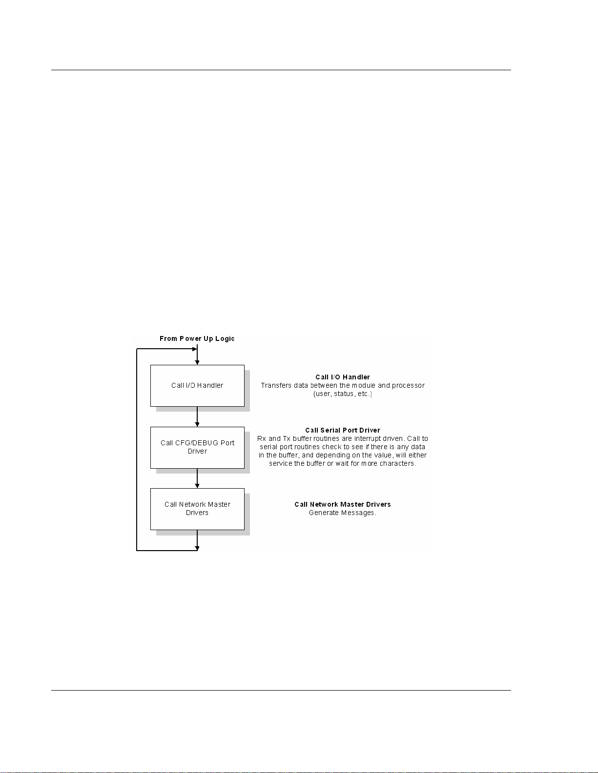
3.1.2 Main Logic Loop
Upon completing the power up configuration process, the module enters an
infinite loop that performs the following functions:
3.1.3 SLC Processor Not in Run
Whenever the module detects that the processor has gone out of the Run mode
(that is, Fault or PGM), the protocol ports can be shut down as prescribed in the
user configuration. When the processor is returned to a running state, the module
will resume communications on the network.
Page 16 of 187 ProSoft Technology, Inc.
September 12, 2006
Page 17
Functional Overview MVI46-103M ♦ SLC Platform
IEC 60870-5-103 Master Communication Module
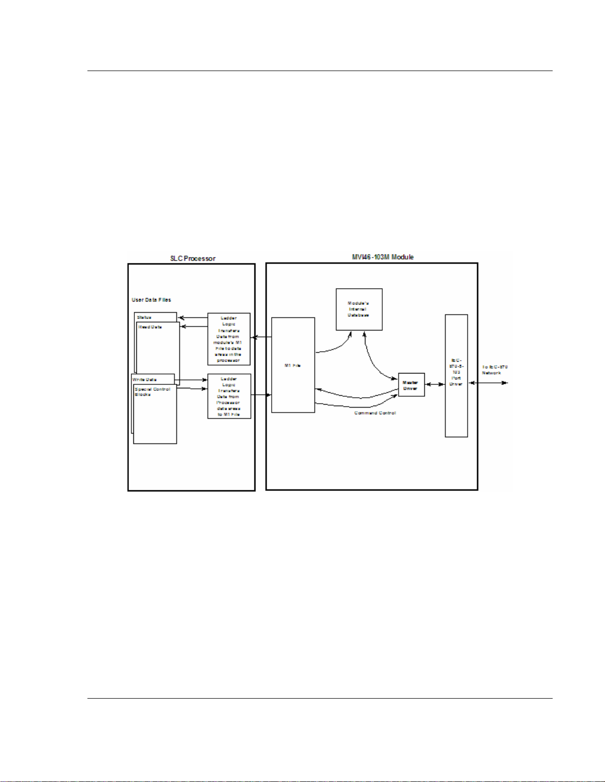
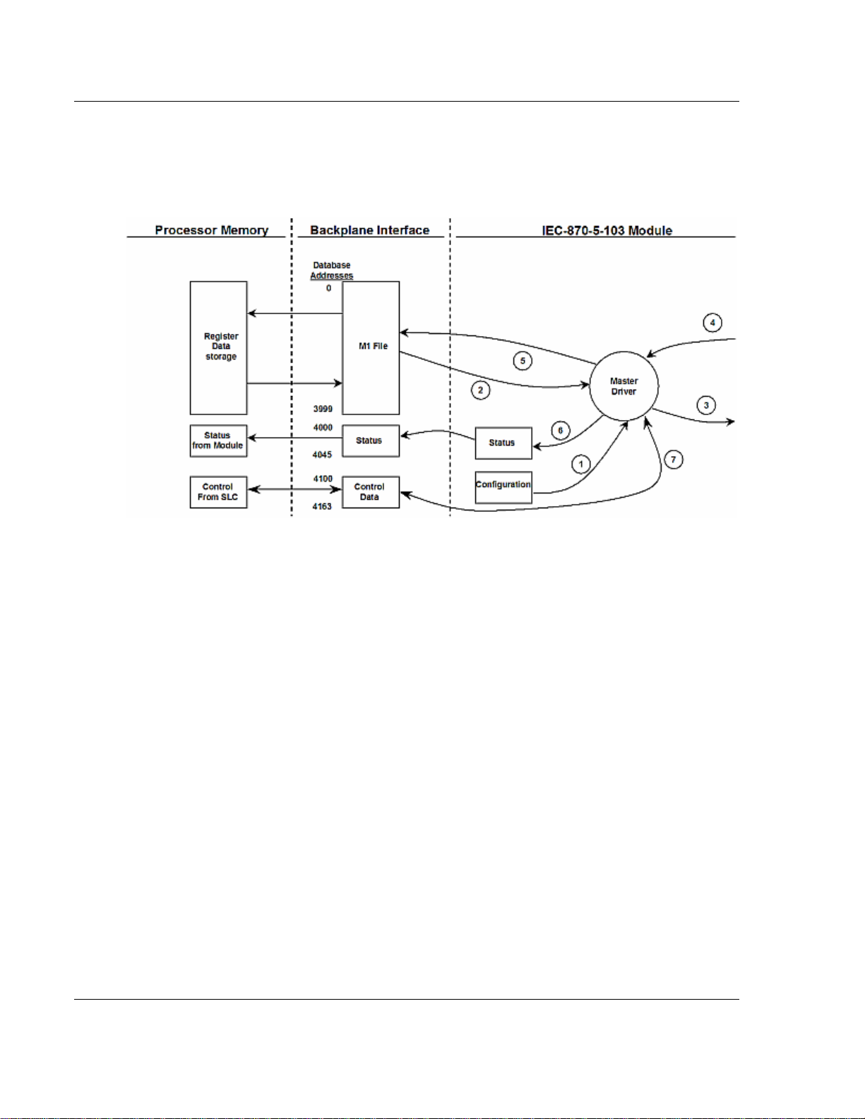
3.1.4 Backplane Data Transfer
The MVI46-103M module is unique in the way it utilizes the SLC backplane. All
data for the module is contained in the module's M1 file. Data is moved between
the module and the SLC processor across the backplane using the module's M1
file. The SLC scan rate and the communication load on the module determine the
update frequency of the M1 file. The COP instruction can be used to move data
between user data files and the module's M1 file.
The following illustration shows the data transfer method used to move data
between the SLC processor, the MVI46-103M module and the IEC 60870-5-103
network.
As shown in the previous diagram, all data transferred between the module and
the processor over the backplane is through the M1 file. Ladder logic must be
written in the SLC processor to interface the M-file data with data defined in the
user-defined data files in the SLC. All data used by the module is stored in its
internal database. Data contained in this database is constantly updated with the
M1 file data by the module and requires no SLC ladder logic to implement. The
user database resides in the M1 file at addresses 0 to 3999. Addresses above
3999 are used for special block control of the module.
3.1.5 Data Types and Mapping
When interfacing data in the processor to that of the IEC 60870-5-103 protocol, it
is important that the user understand the mapping of the data types to their
corresponding representation in the modules database. The table that follows
ProSoft Technology, Inc. Page 17 of 187
September 12, 2006
Page 18

MVI46-103M ♦ SLC Platform Functional Overview
IEC 60870-5-103 Master Communication Module
lists the data types supported by the module and their associated storage
representation:
Type
ID
1
2
3
4
5
9
20
* The words should be swapped in the ladder logic.
Description Data Representation
Time-tagged messages with each data
point represented by two bits.
Time-tagged messages with relative time
with each point represented by two bits.
Measurands with quality descriptor. The
lower 3 bits of the values represented in
this data type contain status information.
The upper 13 bits of the value contained a
signed, 12-bit number. This data type will
return from 1 to 4 values. The number of
words received is dependant on the
information object number and the slave
device.
Time-tagged measurands with relative time
with the value in the packet represented by
a single floating point number.*
Identification data composed of 12
characters of data. Each point in defined of
this data type should reserve 12 bytes (6word addresses) in the database for the
data received.
Measurands with quality descriptor. The
lower 3 bits of the values represented in
this data type contain status information.
The upper 13 bits of the value contained a
signed, 12-bit number. This data type will
return from 1 to 9 values (some slaves
may return up to 16 values). The number
of words received is dependant on the
information object number and the slave
device.
General command to control a dual-point
object. Each command issued by the
module uses the values of two adjacent
bits in the database or an override value
specified by the user command.
Dual-bit status (7.2.6.5 with 00b
(0 decimal) = not used
01b (1 decimal) = Off,
10b (2 decimal) = On and
11b (3 decimal) = not used
Dual-bit status (7.2.6.5 with 00b
(0 decimal) = not used
01b (1 decimal) = Off,
10b (2 decimal) = On and
11b (3 decimal) = not used
Measurand with quality descriptor (7.2.6.8)
Bit 0: 0 = No overflow, 1 = Overflow
Bit 1: 0 = Valid, 1 = Invalid
Bit 2: Reserved
Bits 3-25: Value from –1..+1-2
Short floating-point number stored in IEEE
STD 754 format (Fraction, Exponent, Sign)
(7.2.6.20)
Byte data as defined in 7.2.6.2. First 8
bytes are characters 1 to 8 and last 4
bytes are manufacture bytes either
decimal (0-255) or as ASCII characters.
Measurand with quality descriptor (7.2.6.8)
Bit 0: 0 = No overflow, 1 = Overflow
Bit 1: 0 = Valid, 1 = Invalid
Bit 2: Reserved
Bits 3-25: Value from –1..+1-2
Dual-bit status (7.2.6.4 with 00b
(0 decimal) = not used
01b (1 decimal) = Off,
10b (2 decimal) = On and
11b (3 decimal) = not used
12
12
Page 18 of 187 ProSoft Technology, Inc.
September 12, 2006
Page 19

Functional Overview MVI46-103M ♦ SLC Platform
IEC 60870-5-103 Master Communication Module
As shown in the table above, all bit types are addressed as bits in the modules
database.
Addressing the Data Types
The following table shows an example of how to address the data types in the
MVI46-103M:
Data Type Address Type Length Example
1 Bit 2 bits
2 Bit 2 bits
3 Word 4 words Address 50 refers to word 50, 51, 52, and 53.
4 Double-word 2 words
5 Bit 12 bits
9 Word 5 words
20 Bit 2 bits
Address 160 refers to first and second bits from
word 10.
Address 160 refers to first and second bits from
word 10.
Address 40 refers to two consecutive words
starting at word 80.
Address 180 refers to 12 consecutive bits
starting at the LSB of word 90.
Address 100 refers to 9 consecutive words
starting at word 100.
Address 160 refers to the first and second bits
from word 10.
Therefore, address 16000 represents bit zero in word 1000 of the module's
database. Short floating-point, 32-bit strings and integrated total values each
occupy a double-word space in the database. Therefore, short float database
address of 100 represents the two words, 200 and 201, in the modules database.
Identification objects are stored as byte values in the modules database.
Identification object address 1000 is stored in the module's database in word
addresses 500 to 505.
When setting the monitored data and commands, each point is defined by its
ASDU type, function code, and information number. Valid function codes are
listed in the following table:
Function Code Symbol Number
Distance Protection T(z) 128
Over-current Protection I>> 160
Transformer Differential
Protection
Line Differential Protection rIl 192
Global Function Type GLB 255
rIt 176
Refer to Protocol Interoperability Documentation for a full listing of the protocol
support offered by the module.
Ladder logic in the SLC can control the module or devices on the serial network
using special control blocks. The following table lists the special control codes
(block numbers) used by the module:
ProSoft Technology, Inc. Page 19 of 187
September 12, 2006
Page 20

MVI46-103M ♦ SLC Platform Functional Overview
IEC 60870-5-103 Master Communication Module
Block Code Descriptions
9901 User Constructed Command
9902 Command Control Block (Add command to Command List Queue)
9903 Event Messages from Master port
9950 Command List Error data
9970 Set SLC time using module's time
9971 Set module's time using SLC time
9998 Warm Boot Request from SLC (Block contains no data)
9999 Cold Boot Request from SLC (Block contains no data)
Registers 4000 to 4099 report module status data. This data area should be
copied to a user file for use in the SLC. MVI46-103M Status Data Area (on page
77) contains a listing of the contents of this data area.
Registers 4200 to 4299 are utilized for the transfer of event messages from the
master driver to the SLC. These data are passed to the module when a value of
9903 is placed in register 4200. The ladder logic should copy the information
contained in the block of data and then set register 4200 to 0 to inform the
module that the messages have been accepted.
Registers 4100 to 4199 are used control of the module by the ladder logic. For
example,
if the processor places a value of 9998 in register 4100, the module will perform
a warm-boot operation. If the processor places a value of 9999 in this register,
the module will perform a cold-boot operation. In this application module, both of
these operations perform the same function. They exit the program and then
restart the program. Many of the program parameters set in the user
configuration must be set at program initialization and cannot be set while the
program is running. Therefore, both functions operate the same.
The command functions supported by the module and there data formats are
discussed in the following section.
3.1.6 Command Control Blocks
Block identification codes greater than 9900 are utilized to perform special
functions in the module when placed in the M-file's 4100 register. Each control
block recognized and used by the module is defined in the following sections:
User Constructed Command Block (9901)
Block identification code 9901 issues one or more user constructed commands.
When the module receives a block 9901 identification code, it will place the
included commands into the command queue.
Page 20 of 187 ProSoft Technology, Inc.
September 12, 2006
Page 21

Functional Overview MVI46-103M ♦ SLC Platform
IEC 60870-5-103 Master Communication Module
Word Offset in
Block
4100 Block ID
4101 Command Count
4102 to 4111 Command #1
4112 to 4121 Command #2
4122 to 4131 Command #3
4132 to 4141 Command #4
4142 to 4151 Command #5
4152 to 4161 Command #6
4161 to 4171 Command #7
4172 to 4181 Command #8
Data Field(s) Description
This field contains the block identification code of 9901
for the block.
This field defines the number of user commands
contained in the block. The valid range for the field is 1
to 8.
Data required to build the user defined command in the
command queue.
Data required to build the user defined command in the
command queue.
Data required to build the user defined command in the
command queue.
Data required to build the user defined command in the
command queue.
Data required to build the user defined command in the
command queue.
Data required to build the user defined command in the
command queue.
Data required to build the user defined command in the
command queue.
Data required to build the user defined command in the
command queue.
The following fields are used for each 10-word record in the command list:
Word Offset Definitions Description
0 Database Index Address in module to associate with the command.
1 Session Index
2 Sector Index Sector index for session as defined in the module.
3 Data Type ASDU data type associated with the command.
4 Function Code Function Code for the command.
5
6 Override Flag Override flag for general command.
7 Override Value Override value for general command.
8 Reserved Reserved for future use.
9 Reserved Reserved for future use.
Point Index *
*Information
Number
Session index defined in the module to associate with
the command.
Information object address for the point on which the
command operates.
Refer to the command list section of this documentation for a detailed definition
of the fields contained in this block. They are the same as those used in
constructed the commands in the command list.
There is no response block built by the module to send back to the processor
after the block is processed. The module will set register 4100 to a value of zero
after the commands have been processed. The commands are placed in the
command queue and issued at a high priority.
ProSoft Technology, Inc. Page 21 of 187
September 12, 2006
Page 22

MVI46-103M ♦ SLC Platform Functional Overview
IEC 60870-5-103 Master Communication Module
This block and block 9902 should be used when controlling double-point data
points in remote units using general commands. This provides complete control
of the slave devices under ladder logic control. Alternatively, the slaves can be
controlled by changing data in the database and having the data be transferred
using pre-constructed commands in the user's command list. Some points only
accept value of on for control (that is, LED reset or activate characteristic). For
these points, block 9901 and 9902 should only be utilized.
Command Control Block (9902)
The block 9902 identification code is used by the processor to send a list of
commands to be placed in the command queue from the user configured
command list. Commands placed in the queue with this method need not have
their enable bit set in the command list.
Word Offset
in Block
4100 Block ID
4101 Command count
4102 to 4161
Data Field(s) Description
This field contains the value of 9902 identifying the enable
command to the module.
This field contains the number of commands to enable in the
command list. Valid values for this field are 1 to 60.
Command
Numbers to
enable
These 60 words of data contain the command numbers in
the command list to enable. The commands in the list will be
placed in the command queue for immediate processing by
the module. The first command in the list has an index of 0.
There is no response to this block by the module. The module will place the
selected commands into the command queue and set register 4100 to a value of
0. If the command references a unit that is not defined, the command will not be
placed in the command queue. Normal processing of the command list will
continue after the commands specified in this block are processed.
For digital output control, the use of block 9901 and 9902 is preferred to the use
of the command list. The exact state of the output can be specified in the
command list and then the command can be enabled through the use of block
9902. When the user wishes to execute this command (knowing the state of the
command), can enable the command with the block 9902 request.
Event Message Block (9903)
Block identification code 9903 sends event messages received on the master
port to the processor.
Note: Events are recognized when using a COT=SPONTANEOUS.
Page 22 of 187 ProSoft Technology, Inc.
September 12, 2006
Page 23

Functional Overview MVI46-103M ♦ SLC Platform
IEC 60870-5-103 Master Communication Module
Block Format for Read
Word Offset in
Block
4200 Block ID
4201 Event Count
4202-4211 Event 1 Event message
4212-4221 Event 2 Event message
4222-4231 Event 3 Event message
4232-4241 Event 4 Event message
4242-4251 Event 5 Event message
4252-4261 Event 6 Event message
4262-4271 Event 7 Event message
4272-4281 Event 8 Event message
4282-4291 Event 9 Event message
Data Field(s) Description
This field contains the block identification code of 9903 for the
block.
This field contains the number of events present in the block.
Values of 1 to 20 are valid.
The format of each 10-word data region in the block is as follows:
Word Offset Definitions Description
0
1 ASDU Type
2
3 Fault Number
4 Sec/mSec
5 Hr/Min.
6 Invalid/DST
7 Relative Time
Session Index/Sector
Index
Function Code/Point
Index*
This field contains the session and sector indices
used to define the controlled unit in the module from
which the event was generated. The MSB contains
the session index and the LSB contains the sector
index.
This field contains the ASDU type code for the data
contained in the message.
This field contains the function code and the point
index associated with the event message. The MSB
contains the function code and the LSB contains the
point index.
This is the fault number for the event if applicable.
Only valid for ASDU types 2 and 4.
This word contains the seconds and millisecond
values with a range of 0 to 59999 time at which the
message was generated by the slave device.
This word contains the hour and minutes the
message was generated by the slave. The MSB
contains the hour and the LSB contains the minute
value.
This word contains two bits that relate to the time
value recorded in the slave device for the message.
Bit 0 corresponds to the validity of the time (0=valid,
1=invalid) and Bit 1 defines if daylight savings time is
used in the time (0=no, 1=yes).
This field contains the relative time value if
applicable to the object. Only valid for ASDU types 2
and 4.
ProSoft Technology, Inc. Page 23 of 187
September 12, 2006
Page 24

MVI46-103M ♦ SLC Platform Functional Overview
IEC 60870-5-103 Master Communication Module
Word Offset Definitions Description
8 to 9 Value
*
Point Index refers to the Data Information Number
This double-word value contains the value for the
point index/function code in the event message. For
ASDU types 1 and 2, this value is only 2 bits wide.
For ASDU type 4, this double-word value contains
the floating-point number (short circuit location).
In order for this feature to be activated, the event pass-through parameter must
be set. When a master driver receives an event message from a controlled
station, it will build an event message corresponding to the event in the event
buffer of the module. This buffer is then sent to the processor when any
messages are present. Therefore, these blocks are sent to the processor on a
high priority. After the block is sent, the event message is removed from the
module's event buffer. The ladder logic should set register 4200 to a value of
zero after processing the event message data.
If too many events are present in the buffer (>200), the module will set the event
message overflow flag in the error/status data area of the normal read data
block. There is no response block to be received by the module from the
processor.
Command List Error Data Block (9950)
Block 9950 identification code requests the Command List Error Table from the
module for the 1000 user configurable commands. The format for the block is
shown in the following table:
Word Offset
in Block
4100 Block ID
4101
4102
Data Field(s) Description
This field contains the value of 9950 identifying the block
type to the module.
Number of
Commands to
report
Start Index of
First Command
This field contains the number of commands to report in the
response message. The value has a range of 1 to 60.
This parameter sets the index in the command list where to
start. The first command in the list has a value of 0. The last
index in the list has a value of MaxCommands –1.
The module will respond to a valid request with a block containing the requested
error information. The format for the block is shown in the following table:
Word Offset
in Block
4100 Done Flag
4101 Block ID
4102
Data Field(s) Description
A value of zero will be placed in this register to indicate the
function is complete and the data is ready.
This field contains the value of 9950 identifying the block
type to the PLC.
Number of
Commands
reported
This field contains the number of commands contained in
the block that must be processed by the PLC. This field will
have a value of 1 to 60.
Page 24 of 187 ProSoft Technology, Inc.
September 12, 2006
Page 25

Functional Overview MVI46-103M ♦ SLC Platform
IEC 60870-5-103 Master Communication Module
Word Offset
Data Field(s) Description
in Block
4103
Start Index of
First Command
This field contains the index in the command list for the first
value in the file. This field will have a value of 0 to
MaxCommands–1.
4104 to 4163
Command List
Errors
Each word of this area contains the last error value recorded
for the command. The command index of the first value
(offset 4) is specified in word 3 of the block. The number of
valid command errors in the block is set in word 2 of the
block. Refer to the command error list to interpret the error
codes reported.
Set SLC Time Block (9970)
Block 9970 identification code requests the module's date and time. Use this data
to set the PLC clock.
Word Offset in
Block
4100 Block ID
Data Field(s) Description
This field contains the value of 9970 identifying the block
type to the module.
The module will respond to a valid block 9970 request with a block containing the
requested date and time. The format for the block is shown in the following table:
Word Offset in
Block
4100 Done Flag
4101 Block ID
4102 Year
4103 Month
4104 Day
4105 Hour
4106 Minute
4107 Seconds
4108 Milliseconds
Data Field(s) Description
A value of zero will be placed in this register to indicate the
function is complete and the data is ready.
This field contains the identification code of 9970 for the
block block.
This field contains the four-digit year to be used with the
new time value.
This field contains the month value for the new time. Valid
entry for this field is in the range of 1 to 12.
This field contains the day value for the new time. Valid
entry for this field is in the range of 1 to 31.
This field contains the hour value for the new time. Valid
entry for this field is in the range of 0 to 23.
This field contains the minute value for the new time. Valid
entry for this field is in the range of 0 to 59.
This field contains the second value for the new time. Valid
entry for this field is in the range of 0 to 59.
This field contains the millisecond value for the new time.
Valid entry for this field is in the range of 0 to 999.
Set Module Time Block (9971)
Block identification code 9971 passes the clock time in the SLC to the module.
The date and time provided will be used to set the module's clock.
ProSoft Technology, Inc. Page 25 of 187
September 12, 2006
Page 26

MVI46-103M ♦ SLC Platform Functional Overview
IEC 60870-5-103 Master Communication Module
Word Offset in
Block
4100 Block ID
4101 Year
4102 Month
4103 Day
4104 Hour
4105 Minute
4106 Seconds
4107 Milliseconds
Data Field(s) Description
This field contains the block identification code of 9971 for
the block.
This field contains the four-digit year to be used with the
new time value.
This field contains the month value for the new time. Valid
entry for this field is in the range of 1 to 12.
This field contains the day value for the new time. Valid
entry for this field is in the range of 1 to 31.
This field contains the hour value for the new time.Valid
entry for this field is in the range of 0 to 23.
This field contains the minute value for the new time. Valid
entry for this field is in the range of 0 to 59.
This field contains the second value for the new time. Valid
entry for this field is in the range of 0 to 59.
This field contains the millisecond value for the new time.
Valid entry for this field is in the range of 0 to 999.
The module does not send a response block to the processor after receiving this
block. The module will set register 4100 to zero after processing the data.
Warm Boot Block (9998)
Block 9998 performs a warm-boot operation on the module. The format of the
block constructed by the processor is as follows:
Offset Description Length
4100 9998 1
In this version of the module, the warm and cold boot processes perform the
same operation as many of the variables that must be initialized are fixed when
the module first boots and cannot be changed after the application starts.
Cold Boot Block (9999)
Block 9999 performs a cold-boot operation on the module. The format of the
block constructed by the processor is as follows:
Offset Description Length
4100 9999 1
In this version of the module, the warm and cold boot processes perform the
same operation as many of the variables that must be initialized are fixed when
the module first boots and cannot be changed after the application starts.
Page 26 of 187 ProSoft Technology, Inc.
September 12, 2006
Page 27
Functional Overview MVI46-103M ♦ SLC Platform
IEC 60870-5-103 Master Communication Module
3.2 Master Driver
The master driver supported on each application port of the module emulates an
IEC 60870-5-103 Master device. Configuration of each port is independent and
should be connected to different serial networks.
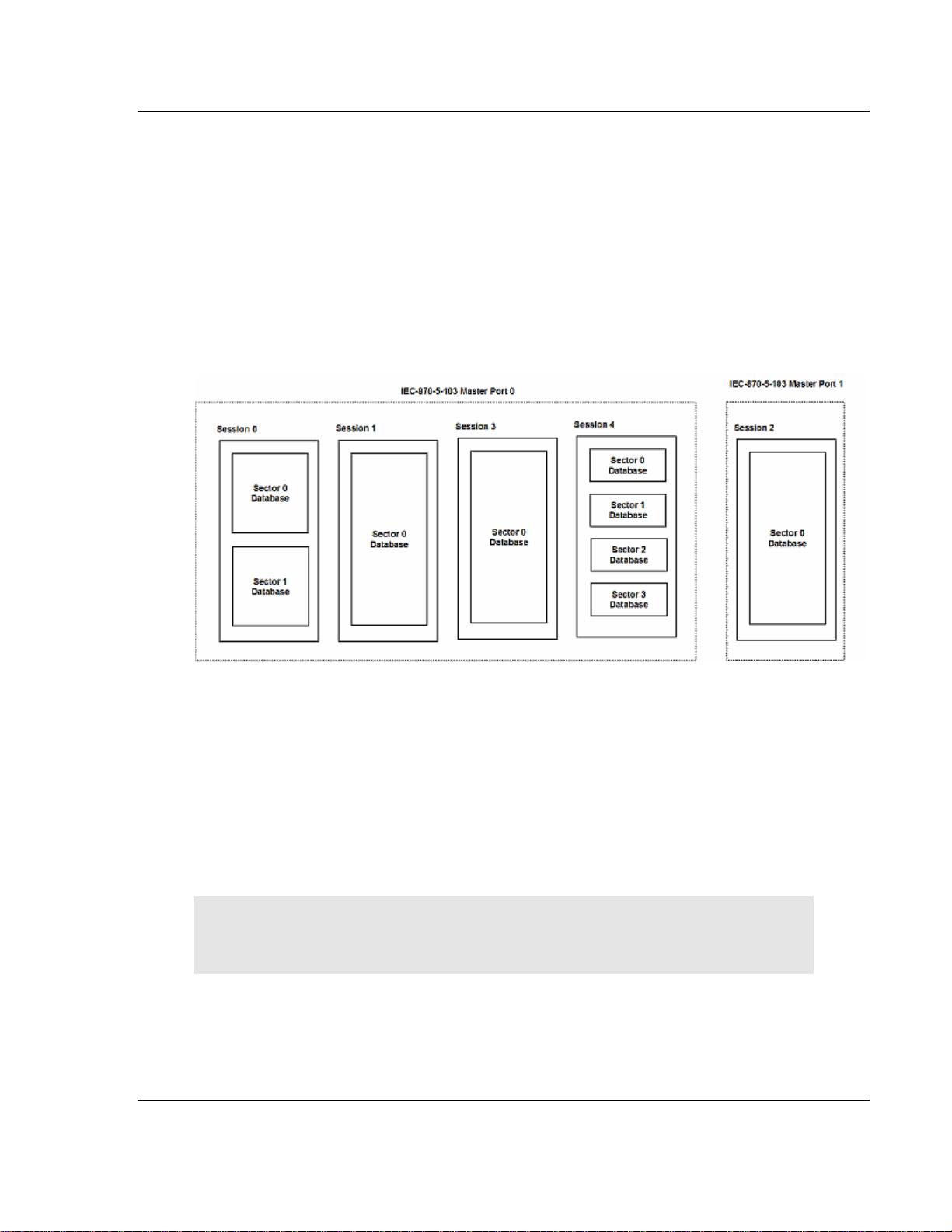
Each port on the module communicates with one or more controlled stations on
what are referred to as sessions. A session represents a controlled device with a
unique data link layer address. Each session (controlled device) contains one or
more data sets (sectors) that are defined by the vendor of the device. The
following illustration shows these relationships.
Port 0 on the module communicates with 4 sessions (0, 1, 3 and 4) each of which
has their own data set(s). Session 1 only has one sector (all data for device
contained in a single database). This sector is addressed by the master using the
Common address of ASDU value set for the sector in the configuration file.
Session 0 contains two sectors each with their own unique Common address of
ASDU value to identify the sector.
Port 1 is connected to one device on the network. This device is defined in the
Session 2 section of the configuration file. In this example, all data of the device
is stored in a single sector.
Note: The IEC 60870-5-103 specification only supports the unbalanced mode.
No support is given in the protocol for the balanced mode and the module
does not support this mode.
The module supports two application ports. Thirty-two sessions can be defined
on the module with each session being assigned to an application port. Within
each session, up to five sectors can be defined. This system permits a very
flexible assignment of resources in the module. The definition of the data
ProSoft Technology, Inc. Page 27 of 187
September 12, 2006
Page 28
MVI46-103M ♦ SLC Platform Functional Overview
IEC 60870-5-103 Master Communication Module
associated with each sector in the system is defined by the user in the
configuration file.
The following diagram illustrates the functionality of the master driver:
1 The master driver is configured as specified by the IEC103M.CFG file
2 The master will construct control commands using the data in the database
3 The master will send these commands and class polls out on the serial
network
4 Response messages or spontaneous messages generated by controlled
devices on the serial network are received by the master driver
5 Monitor data received by the master is passed to the module's database and
passed to the processor
6 Additionally, status data for the module is passed to the processor
Page 28 of 187 ProSoft Technology, Inc.
September 12, 2006
Page 29

Module Configuration MVI46-103M ♦ SLC Platform IEC 60870-5-103 Master Communication Module
4 Module Configuration
In This Chapter
Installing and Configuring the Module .................................... 29
Module Data........................................................................... 31
Configuration File ................................................................... 31
Uploading and Downloading the Configuration File ............... 35
This section contains the setup procedure, data, and ladder logic for successful
application of the MVI46-103M module. Each step in the setup procedure is
defined in order to simplify the use of the module.
4.1 Installing and Configuring the Module
This chapter describes how to install and configure the module to work with your
application. The configuration process consists of the following steps.
1 Use RSLogix to identify the module to the processor and add the module to a
project.
NOTE: The RSLogix software must be in "offline" mode to add the module to a
project.
2 Modify the module's configuration files to meet the needs of your application,
and copy the updated configuration to the module. Example configuration
files are provided on the CD-ROM.
3 Modify the example ladder logic to meet the needs of your application, and
copy the ladder logic to the processor. Example ladder logic files are provided
on the CD-ROM.
Note: If you are installing this module in an existing application, you can copy
the necessary elements from the example ladder logic into your application.
The rest of this chapter describes these steps in more detail.
ProSoft Technology, Inc. Page 29 of 187
September 12, 2006
Page 30
MVI46-103M ♦ SLC Platform Module Configuration
IEC 60870-5-103 Master Communication Module
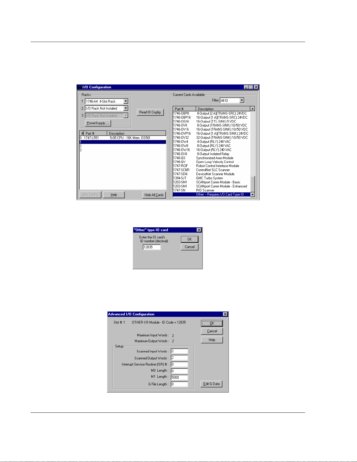
The first step in installing and configuring the module is to define the module to
the system. Select the I/O Configuration option from the program screen. This
displays the following dialog box:
Select the Other module from the list. This action opens the following dialog box.
Enter the module I/O card ID number as 12835, and then select the OK
command button. Double-click the mouse on the module just added to the rack.
Fill in the dialog box presented as shown in the following screen shot:
Page 30 of 187 ProSoft Technology, Inc.
September 12, 2006
Page 31

Module Configuration MVI46-103M ♦ SLC Platform
IEC 60870-5-103 Master Communication Module
Select the OK command button to apply these settings to the module. Then,
close the I/O Configuration dialog box.
The next step in the module's setup is to define the user defined data areas to
hold the status and read and write database areas. Edit the IEC103M.CFG file
now for the application to implement. Use any text editor to set the values in the
file. You must retain the file name, IEC103M.CFG.
The last step in the module setup is to add the ladder logic. If the example ladder
logic is used, adjust the ladder to fit the application. When the ladder example is
not used, copy the example ladder logic to your application and alter as
necessary.
The module is now set up and ready to be used with your application. Insert the
module in the rack and attach the serial communication cables. Download the
IEC103M.CFG file to the module. Download the new application to the controller
and place the processor in run mode. If all the configuration parameters are set
correctly and the module is attached to a network, the module's Application LED
(APP LED) should remain off and the backplane activity LED (BP ACT) should
blink very rapidly. Refer to the Troubleshooting section if you encounter errors.
Attach a computer or terminal to Debug/Configuration port on the module and
check the status of the module using the resident debugger in the module.
4.2 Module Data
All data related to the MVI46-103M module is stored in a user defined data files
and the module's M1 file. Files should be defined for each data type to be used
with the module. Additionally, a file should be defined to hold the module status
data. The status data should be copied from the M1 file and placed in the
assigned status file. Input (monitor) data should be copied from the user file to
the M1 file and output (command) data should be copied from the user files to
the M1 file.
4.3 Configuration File
The module requires a configuration file (IEC103M.CFG) to operate. This
configuration file configures the module's master drivers, sets up the databases
for the controlled devices and establishes a command list. Each parameter in the
file must be set carefully in order for the application to be implemented
successfully.
The configuration file contains at least the following seven sections with topic
header names enclosed in [ ] characters.:
[Backplane Configuration] Backplane tran sfer p arameter section
[IEC-870-5-103 Master] General Configuration for driver
[IEC-870-5-103 Master Port 0] Configuration for first application port
ProSoft Technology, Inc. Page 31 of 187
September 12, 2006
Page 32

MVI46-103M ♦ SLC Platform Module Configuration
IEC 60870-5-103 Master Communication Module
[Backplane Configuration] Backplane tran sfer p arameter section
[IEC-870-5-103 Master Port 1] Configuration for second application port
[IEC-103 Master Session x] Definition for each control unit
[IEC-103 Master Session x Sector y] Definition for each sector in each controlled unit
[IEC-103 Master Commands] Command list to control slave units
A set of parameters follows each each section header. Use unique labels under
each section to specify a parameter. Each label in the file must be entered
exactly as shown in the file for the parameter to be identified by the program. If
the module is not considering a parameter, check the label for the data item.
Each parameter's value is separated from the label with the ':' character. This
character is used by the program to delimit the position in the data record where
to start reading data. All data for a parameter must follow the ':' character. There
must be at least one space character between the end of the parameter value
and the following text. An example of a parameter entry is given below:
Baud Rate : 19200 #Baud rate for master port
The parameter label is "Baud Rate" and the parameter value is 19200. The
characters after a numeric parameter value are ignored and can be used to
document the configuration file.
Any record that begins with the '#' character is considered to be a comment.
Comments can be placed anywhere in the file so long as the '#' character is the
first column of the line. Liberal use of comments within the file can ease the use
and interpretation of the data in the file.
Use any text editor to alter the supplied IEC103M.CFG file for the specific
application. You must enter each parameter correctly for successful application
of the module. MVI46-103M Configuration Data Definition (on page 82)
contains a complete listing and definition of all parameters utilized by the module.
The session sections of the configuration file are determined by the number of
sessions set in the configuration file. The sessions are referenced by a zero
based index value. For example, if the module is configured for four sessions, the
configuration file should contain sections for sessions 0 to 3 (that is, [IEC-103
Master Session 0] to [IEC-103 Master Session 3]. Each of these sections will
define the characteristics of the specific controlled device to be interfaced. Within
each session definition, is a parameter that specifies the number of sectors for
the session. For each sector defined for a session, there must exist a [IEC-103
Master Session x Sector y] section. Where the x value represents the session
index and the y value represents sector index. For example if session 0 contains
1 sector, there must be a section with the following name in the configuration file:
[IEC-103 Master Session 0 Sector 0]. The specific sector parameter set and
database is defined in this section.
The last section of the configuration file is the command list definition ([IEC-103
Master Commands]). This section can contain up to 1000 user defined
commands to be executed by the module and sent to the controlled devices.
There is no need to place Class 1 or Class 2 polls in the this list for the controlled
Page 32 of 187 ProSoft Technology, Inc.
September 12, 2006
Page 33

Module Configuration MVI46-103M ♦ SLC Platform
IEC 60870-5-103 Master Communication Module
devices as the master driver for each port will execute these automatically when
the port is idle. In order for the port to be idle, make sure that there is idle time
available and that the commands do not constantly utilize the ports. The
command list section starts with a reserved label START and ends with the label
END. Each row in the file corresponds to an individual command with the first
character position in each row left blank (white space). The contents of each
command record is outlined in the following table:
Col Field Description
1
2
3
4 Session
5 Sector
Enable
Code
Database
Index
Poll
Interval
This field determines when the command will be executed according to the
following codes:
0=Command is disabled and will only execute if enabled from PLC
processor
1=Command will execute no more frequently than the time set in the Poll
interval
2=Command will execute when the last value read in the database differs
from the current value
This field specifies the location in the module's internal database to
associate with the command. The data type used in the command
determines addressing of the index as follows:
Type Description DB Index type
0 Special command *Word address
6 Time synchronization *Word address
7 General interrogation *Word address
20
*Word address = Value only used to signal when to send event (Enable
Code = 2)
This parameter is used if the Enable Code field is set to a value of 1. It
sets the minimum number of seconds to delay between successive
execution of the command.
This parameter is utilized to associate the command with one of the
sessions defined for the module.
This parameter associates the command with the proper sector of the
selected session.
General command (2
bit control)
Bit address
ProSoft Technology, Inc. Page 33 of 187
September 12, 2006
Page 34

MVI46-103M ♦ SLC Platform Module Configuration
IEC 60870-5-103 Master Communication Module
Col Field Description
1
6 Data Type
7
8
9
10
* The Point Index is the Data Information Number.
Enable
Code
Function
Code
Point
Index
Override
Flag
Override
Value
This field determines when the command will be executed according to the
following codes:
0=Command is disabled and will only execute if enabled from PLC
processor
1=Command will execute no more frequently than the time set in the Poll
interval
2=Command will execute when the last value read in the database differs
from the current value
This parameter sets the ASDU data type to be used with the message.
The codes specified are those defined for the IEC-870-5-103 protocol. The
following is a listing of command control data types supported in this
module:
Type Description
0 Special command
6 Time synchronization
7 General interrogation
20 General command (2 bit control)
The type 0 is not defined in the protocol specification but is added to the
module application to perform special commands. The command to be
issued is determined by the value of the function field. If the function is set
to 1, the module will issue a reset process command to the session
specified. If the function is set to 2, the module will a class 2 poll to the
selected session.
This parameter specifies the function code as specified in the protocol
specification except when Data Type code 0 is used. For the general
commands, this field is used in conjunction with the Point Index to
determine the point to control in the remote slave device. For the special
commands, a value of 1 performs a reset process and 2 to issue a class 2
poll.
This parameter along with the Function Code determines the point to
control in the remote device when the general command is utilized. For all
other commands this field is ignored.
This field is used with general commands to determine if the override or
database value should be used with the command. If the flag is set to 0,
the value in the module's database will be sent when the command is
issued. If the flag is set to 1 (or non-zero value), the value set in the
Override Value will be sent with the command. When the override flag and
value are utilized, the Enable Code 2 and Database Index can be used to
trigger the execution of the command.
This parameter specifies the override value to use with the command if the
Override Flag is set. This value should have one of the following values:
1=Off and 2=On. Other values maybe valid for certain controlled
As an alternative to using a command list, blocks with an identification code of
9901 can be used to issue commands from the ladder logic.
Page 34 of 187 ProSoft Technology, Inc.
September 12, 2006
Page 35

Module Configuration MVI46-103M ♦ SLC Platform
IEC 60870-5-103 Master Communication Module
4.4 Uploading and Downloading the Configuration File
ProSoft modules are shipped with a pre-loaded configuration file. In order to edit
this file, you must transfer the file from the module to your PC. After editing, you
must transfer the file back to the module.
This section describes these procedures.
Important: The illustrations of configuration/debug menus in this section are
intended as a general guide, and may or may not exactly match the
configuration/debug menus in your own module. For specific details about the
configuration/debug menus in your module, please refer to The
Configuration/Debug Menu (on page 47).
4.4.1 Transferring the Configuration File to Your PC
1 Connect your PC to the Configuration/Debug port of the module using a
terminal program such as HyperTerminal. Press [?] to display the main
menu.
2 Press [S] (Send Module Configuration). The message "Press Y key to
confirm configuration send!" is displayed at the bottom of the screen.
ProSoft Technology, Inc. Page 35 of 187
September 12, 2006
Page 36
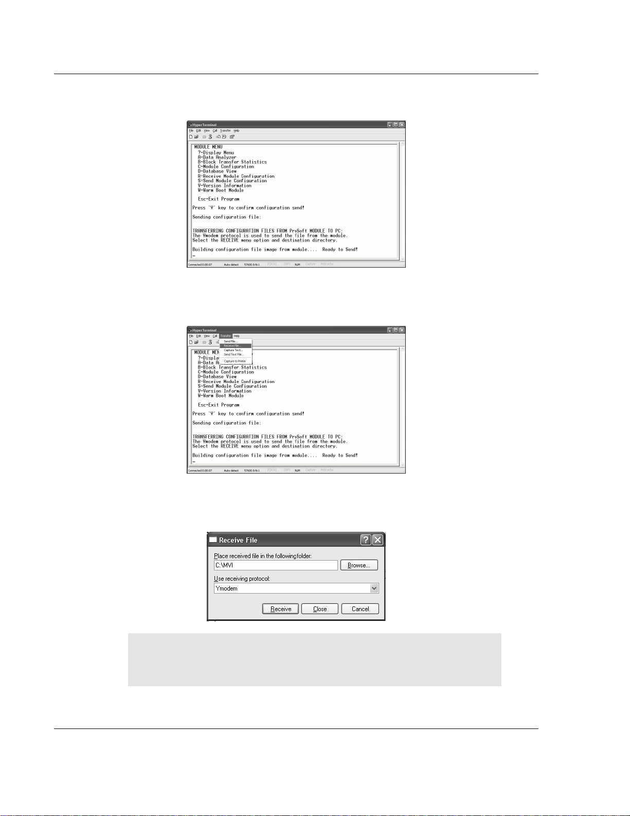
MVI46-103M ♦ SLC Platform Module Configuration
IEC 60870-5-103 Master Communication Module
3 Press [Y]. The screen now indicates that the module is ready to send.
4 From the Transfer menu in HyperTerminal, select Receive File. This action
opens the Receive File dialog box.
5 Use the Browse button to choose a folder on your computer to save the file,
and then click Receive.
• Note: ProSoft Technology suggests that you download the
configuration file pre-loaded on your module. However, configuration
files are also available on the ProSoft CD as well as the ProSoft
Technology web site at http://www.prosoft-technology.com.
6 Select Ymodem as the receiving protocol.
Page 36 of 187 ProSoft Technology, Inc.
September 12, 2006
Page 37

Module Configuration MVI46-103M ♦ SLC Platform
IEC 60870-5-103 Master Communication Module
7 Click the Receive button. This action opens the Ymodem File Receive dialog
box, showing the progress of your file transfer.
When the configuration file has been transferred to your PC, the dialog box
will indicate that the transfer is complete.
The configuration file is now on your PC at the location you specified.
8 You can now open and edit the file in a text editor such as Notepad. When
you have finished editing the file, save it and close Notepad.
4.4.2 Transferring the Configuration File to the Module
Perform the following steps to transfer a configuration file from your PC to the
module.
ProSoft Technology, Inc. Page 37 of 187
September 12, 2006
Page 38

MVI46-103M ♦ SLC Platform Module Configuration
IEC 60870-5-103 Master Communication Module
1 Connect your PC to the Configuration/Debug port of the module using a
terminal program such as HyperTerminal. Press [?] to display the main
menu.
2 Press [S] (Receive Module Configuration). The message "Press Y key to
confirm configuration receive!" is displayed at the bottom of the screen.
3 Press [Y]. The screen now indicates that the PC is ready to send.
Page 38 of 187 ProSoft Technology, Inc.
September 12, 2006
Page 39

Module Configuration MVI46-103M ♦ SLC Platform
IEC 60870-5-103 Master Communication Module
4 From the Transfer menu in HyperTerminal, select Send File.
The Send File dialog appears.
5 Use the Browse button to locate the configuration file your computer.
Note: This procedure assumes that you are uploading a newly edited
configuration file from your PC to the module. However, configuration files are
also available on the ProSoft CD as well as the ProSoft Technology web site at
http://www.prosoft-technology.com.
6 Select Ymodem as the protocol.
ProSoft Technology, Inc. Page 39 of 187
September 12, 2006
Page 40

MVI46-103M ♦ SLC Platform Module Configuration
IEC 60870-5-103 Master Communication Module
7 Click the Send button. This action opens the Ymodem File Send dialog box.
When the file transfer is complete, the module's configuration/debug screen
indicates that the module has reloaded program values, and displays
information about the module.
8 Your module now contains the new configuration.
Page 40 of 187 ProSoft Technology, Inc.
September 12, 2006
Page 41

Ladder Logic MVI46-103M ♦ SLC Platform IEC 60870-5-103 Master Communication Module
5 Ladder Logic
In This Chapter
Main Routine.......................................................................... 41
Data Transfer (U:3) ................................................................ 42
Control Routine (U:4) ............................................................. 43
Ladder logic is required for application of the MVI46-103M module. Tasks that
must be handled by the ladder logic are data transfer, special block handling and
status data receipt. This section discusses each aspect of the ladder logic as
required by the module. Additionally, a power-up handler should be written to
handle the initialization of the module's data and to clear any processor fault
conditions.
5.1 Main Routine
The main routine is used to call the data transfer and control subroutines. An
example of the main routine is shown in the following two rungs:
ProSoft Technology, Inc. Page 41 of 187
September 12, 2006
Page 42
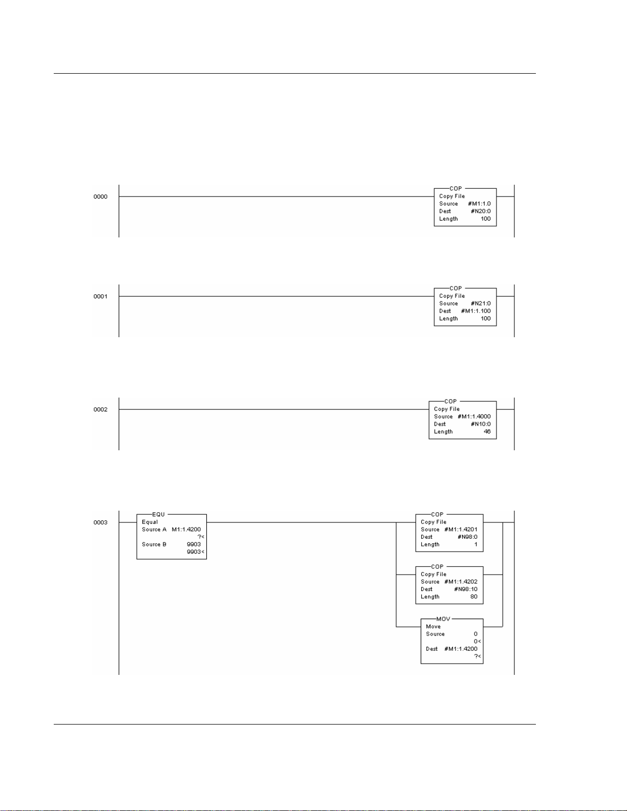
MVI46-103M ♦ SLC Platform Ladder Logic
IEC 60870-5-103 Master Communication Module
5.2 Data Transfer (U:3)
The data transfer routine is responsible for placing all the output data into the M1
file and for retrieving all the input data from the M1 file. The following two rungs
transfer the data between the M1 file and the user data files. The first rung
transfers monitored data received by the master driver into the user data files.
The following rung transfers the control data from the SLC to the master driver.
The next rung transfers the module's status data to a user data file. A rung to
perform this operation is as follows:
The last rung displays a simple example of retrieving event message data from
the M1 file:
After the data is moved to the user file, word 4200 in the M1 file is set to zero.
This informs the module that the message was received and that more
Page 42 of 187 ProSoft Technology, Inc.
September 12, 2006
Page 43
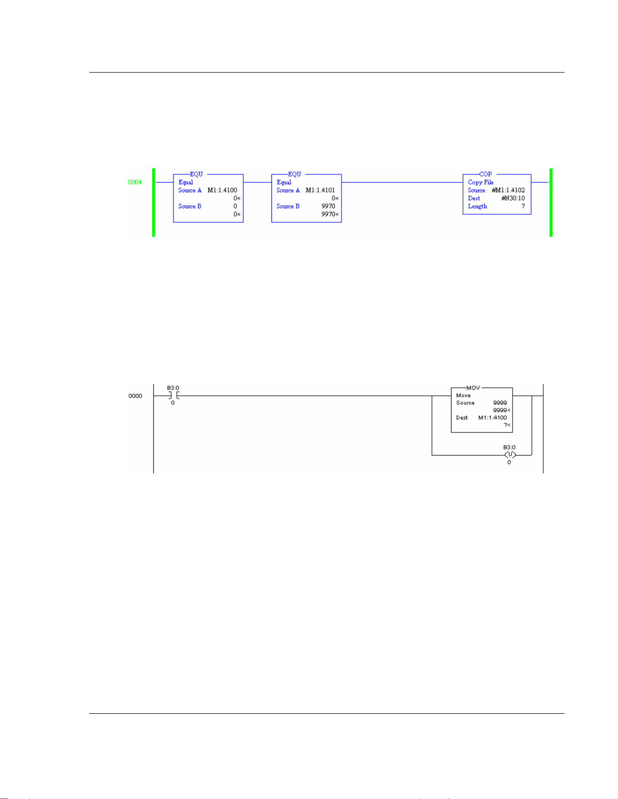
Ladder Logic MVI46-103M ♦ SLC Platform
IEC 60870-5-103 Master Communication Module
messages can be accepted. More ladder logic is required if this data is to be
utilized by the processor or an attached data logger.
The next rung shows how to handle a module response to block 9970 in order to
read the date and time information from the MVI module:
5.3 Control Routine (U:4)
The control routine is responsible for controlling the module or handling requests
from the module using the control registers (M1:1.4100 to 4199).
The following rung requests the cold-boot operation for the module. Placing the
value 9999 in the first control register makes this request. When the module
recognizes this value in the control register, it performs the cold-boot operation.
ProSoft Technology, Inc. Page 43 of 187
September 12, 2006
Page 44

MVI46-103M ♦ SLC Platform Ladder Logic
IEC 60870-5-103 Master Communication Module
The next rung displays an example of building a 9901 block to send a user
command to a controlled device:
This rung copies the command to issue from the user file into the M1 file and sets
the command count to 1. The last operation on the M1 file is to set the command
code 9901 in to the file. The module will place all valid commands received in
9901 blocks into the command queue for execution.
The next rung demonstrates the use of the 9902 block:
This rung requests that the single command number 1 in the user command list
be placed into the command queue.
Page 44 of 187 ProSoft Technology, Inc.
September 12, 2006
Page 45

Ladder Logic MVI46-103M ♦ SLC Platform
IEC 60870-5-103 Master Communication Module
The next rung shows how to write date and time information to the MVI46-103M
module using block 9971:
The last rung shows how to request date and time information from the module
using block 9970. The module response is handled in the Data Transfer routine.
ProSoft Technology, Inc. Page 45 of 187
September 12, 2006
Page 46

MVI46-103M ♦ SLC Platform Ladder Logic
IEC 60870-5-103 Master Communication Module
Page 46 of 187 ProSoft Technology, Inc.
September 12, 2006
Page 47

Diagnostics and Troubleshooting MVI46-103M ♦ SLC Platform IEC 60870-5-103 Master Communication Module
6 Diagnostics and Troubleshooting
In This Chapter
The Configuration/Debug Menu ............................................. 47
Required Hardware ................................................................ 48
Required Software ................................................................. 49
Using the Configuration/Debug Port....................................... 49
LED Status Indicators ............................................................ 69
This section provides information on diagnostics and troubleshooting in three
forms:
Status data values are transferred from the module to the controller tags in
the SLC processor.
All data contained in the module can be viewed through the
Configuration/Debug port attached to a terminal emulator.
LED status indicators on the front of the module provide information on the
modules status.
6.1 The Configuration/Debug Menu
The Configuration and Debug menu for this module is arranged as a tree
structure, with the Main Menu at the top of the tree, and one or more sub-menus
for each menu command. The first menu you see when you connect to the
module is the Main menu.
Because this is a text-based menu system, you enter commands by typing the
command letter from your computer keyboard in the terminal application (for
example, HyperTerminal). The module does not respond to mouse movements
or clicks. The command executes as soon as you press the command letter —
you do not need to press [Enter]. When you type a command letter, a new
screen will be displayed in your terminal application.
6.1.1 Navigation
All of the sub-menus for this module contain commands to redisplay the menu or
return to the previous menu. You can always return from a sub-menu to the next
higher menu by pressing [Z] on your keyboard.
ProSoft Technology, Inc. Page 47 of 187
September 12, 2006
Page 48

MVI46-103M ♦ SLC Platform Diagnostics and Troubleshooting
IEC 60870-5-103 Master Communication Module
The organization of the menu structure is represented in simplified form in the
following illustration:
The remainder of this section shows you the menus available for this module,
and briefly discusses the commands available to you.
Keystrokes
The keyboard commands on these menus are almost always non-case sensitive.
You can enter most commands in lower case or capital letters.
The menus use a few special characters ([?], [-], [+], [@]) that must be entered
exactly as shown. Some of these characters will require you to use the [Shift],
[Ctrl] or [Alt] keys to enter them correctly. For example, on US English
keyboards, enter the [?] command as [Shift][/].
Also, take care to distinguish capital letter [I] from lower case letter [l] (L) and
number [1]; likewise for capital letter [O] and number [0]. Although these
characters look nearly the same on the screen, they perform different actions on
the module.
6.2 Required Hardware
You can connect directly from your computer's serial port to the serial port on the
module to view configuration information, perform maintenance, and send
(upload) or receive (download) configuration files.
ProSoft Technology recommends the following minimum hardware to connect
your computer to the module:
80486 based processor (Pentium preferred)
1 megabyte of memory
At least one serial communications port available
A null modem serial cable.
Page 48 of 187 ProSoft Technology, Inc.
September 12, 2006
Page 49

Diagnostics and Troubleshooting MVI46-103M ♦ SLC Platform
IEC 60870-5-103 Master Communication Module
6.3 Required Software
In order to send and receive data over the serial port (COM port) on your
computer to the module, you must use a communication program (terminal
emulator).
A simple communication program called HyperTerminal is pre-installed with
recent versions of Microsoft Windows operating systems. If you are connecting
from a machine running DOS, you must obtain and install a compatible
communication program. The following table lists communication programs that
have been tested by ProSoft Technology.
DOS ProComm, as well as several other terminal emulation programs
Windows 3.1 Terminal
Windows 95/98 HyperTerminal
Windows NT/2000/XP HyperTerminal
The module uses the Ymodem file transfer protocol to send (download) and
receive (upload) configuration files from your computer. If you use a
communication program that is not on the list above, please be sure that it
supports Ymodem file transfers.
6.4 Using the Configuration/Debug Port
To connect to the module's Configuration/Debug port:
1 Connect your computer to the module's port using a null modem cable.
2 Start the communication program on your computer and configure the
communication parameters with the following settings:
Baud Rate 57,600
Parity None
Data Bits 8
Stop Bits 1
Software Handshaking XON/XOFF
3 Open the connection. When you are connected, press the [?] key on your
keyboard. If the system is set up properly, you will see a menu with the
module name followed by a list of letters and the commands associated with
them.
If there is no response from the module, follow these steps:
1 Verify that the null modem cable is connected properly between your
computer's serial port and the module. A regular serial cable will not work.
2 Verify that your communication software is using the correct settings for baud
rate, parity and handshaking.
ProSoft Technology, Inc. Page 49 of 187
September 12, 2006
Page 50

MVI46-103M ♦ SLC Platform Diagnostics and Troubleshooting
IEC 60870-5-103 Master Communication Module
3 On computers with more than one serial port, verify that your communication
program is connected to the same port that is connected to the module.
If you are still not able to establish a connection, you can contact ProSoft
Technology, Inc. Technical Support for further assistance.
6.4.1 Main Menu
When you first connect to the module from your computer, your terminal screen
will be blank. To activate the main menu, press the [?] key on your computer's
keyboard. If the module is connected properly, the following menu will appear on
your terminal screen:
Caution: Some of the commands available to you from this menu are
designed for advanced debugging and system testing only, and can cause the
module to stop communicating with the processor or with other devices,
resulting in potential data loss or other failures. Only use these commands if
you are specifically directed to do so by ProSoft Technology, Inc. Technical
Support staff. Some of these command keys are not listed on the menu, but
Page 50 of 187 ProSoft Technology, Inc.
September 12, 2006
Page 51

Diagnostics and Troubleshooting MVI46-103M ♦ SLC Platform
IEC 60870-5-103 Master Communication Module
are active nevertheless. Please be careful when pressing keys so that you do
not accidentally execute an unwanted command.
Viewing Block Transfer Statistics
Press [B] from the Main Menu to view the Block Transfer Statistics screen.
Use this command to display the configuration and statistics of the backplane
data transfer operations between the module and the processor. The information
on this screen can help determine if there are communication problems between
the processor and the module.
Tip: To determine the number of blocks transferred each second, mark the
numbers displayed at a specific time. Then some seconds later activate the
command again. Subtract the previous numbers from the current numbers and
divide by the quantity of seconds passed between the two readings.
Viewing Module Configuration
Press [C] to view the Module Configuration screen.
Use this command to display the current configuration and statistics for the
module.
Opening the Database Menu
Press [D] to open the Database View menu. Use this menu command to view the
current contents of the module's database.
Opening the IEC-103 Master Menu
Press [I] from the Main Menu to open the IEC-870-5-103 Master Driver Menu.
Use this menu command to view detailed configuration information for the
module.
For more information about the commands on this menu, refer to IEC-103
Master Driver Menu (on page 56).
ProSoft Technology, Inc. Page 51 of 187
September 12, 2006
Page 52

MVI46-103M ♦ SLC Platform Diagnostics and Troubleshooting
IEC 60870-5-103 Master Communication Module
Viewing the Backplane Command List
Press [P] from the Main Menu to view the Backplane Data Exchange List. Use
this command to display the configuration and statistics of the backplane data
transfer operations.
Tip: Repeat this command at one-second intervals to determine the number of
blocks transferred each second.
Receiving the Configuration File
Press [R] to download (receive) the current configuration file from the module.
For more information on receiving and sending configuration files, please see
Uploading and Downloading the Configuration File (on page 35).
Sending the Configuration File
Press [S] to upload (send) an updated configuration file to the module. For more
information on receiving and sending configuration files, please see Uploading
and Downloading the Configuration File (on page 35).
Viewing Version Information
Press [V] to view Version information for the module.
Use this command to view the current version of the software for the module, as
well as other important values. You may be asked to provide this information
when calling for technical support on the product.
Values at the bottom of the display are important in determining module
operation. The Program Scan Counter value is incremented each time a
module's program cycle is complete.
Page 52 of 187 ProSoft Technology, Inc.
September 12, 2006
Page 53

Diagnostics and Troubleshooting MVI46-103M ♦ SLC Platform
IEC 60870-5-103 Master Communication Module
Tip: Repeat this command at one-second intervals to determine the frequency
of program execution.
Exiting the Program
Caution: Some of the commands available to you from this menu are
designed for advanced debugging and system testing only, and can cause the
module to stop communicating with the processor or with other devices,
resulting in potential data loss or other failures. Only use these commands if
you are specifically directed to do so by ProSoft Technology, Inc. Technical
Support staff. Some of these command keys are not listed on the menu, but
are active nevertheless. Please be careful when pressing keys so that you do
not accidentally execute an unwanted command.
Press [Esc] to exit the program and display the operating system prompt. This
command will cause the module to cease operation and stop transferring data
between the ports and the module, and between the processor and the module.
This could interrupt a currently running process. Only use this command if
instructed to do so by the ProSoft Technical Support Group.
Warm Booting the Module
Caution: Some of the commands available to you from this menu are
designed for advanced debugging and system testing only, and can cause the
module to stop communicating with the processor or with other devices,
resulting in potential data loss or other failures. Only use these commands if
you are specifically directed to do so by ProSoft Technology, Inc. Technical
Support staff. Some of these command keys are not listed on the menu, but
are active nevertheless. Please be careful when pressing keys so that you do
not accidentally execute an unwanted command.
Press [W] from the Main Menu to warm boot (restart) the module. This command
will cause the program to exit and reload, refreshing configuration parameters
that must be set on program initialization. Only use this command if you must
force the module to re-boot.
ProSoft Technology, Inc. Page 53 of 187
September 12, 2006
Page 54
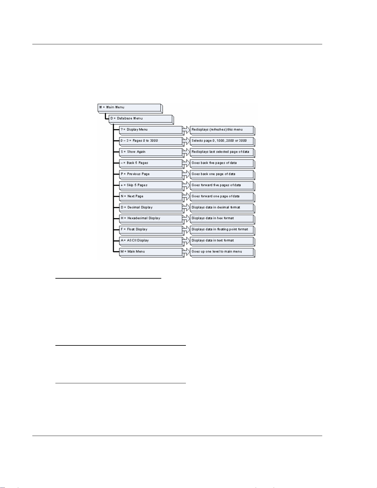
MVI46-103M ♦ SLC Platform Diagnostics and Troubleshooting
IEC 60870-5-103 Master Communication Module
6.4.2 Database View Menu
Press [D] from the Main Menu to open the Database View menu. Use this menu
command to view the current contents of the module's database. Press [?] to
view a list of commands available on this menu.
Viewing Database Pages 0 to 3000
The database is divided into pages that correspond with a specific number of
registers. The total number of database pages and registers depends on the
memory capacity and configuration of the module.
Use the keyboard commands [0] through [3] to display database contents
starting from 0 (zero), 1000, 2000 and 3000 respectively.
Moving Back Through 5 Pages of Registers
Press [-] from the Database View menu to skip back to the previous 500
registers of data.
Viewing the Previous 100 Registers of Data
Press [P] from the Database View menu to display the previous 100 registers of
data.
Page 54 of 187 ProSoft Technology, Inc.
September 12, 2006
Page 55

Diagnostics and Troubleshooting MVI46-103M ♦ SLC Platform
IEC 60870-5-103 Master Communication Module
Skipping 500 Registers of Data
Hold down [Shift] and press [=] to skip forward to the next 500 registers of data.
Viewing the Next 100 Registers of Data
Press [N] from the Database View menu to select and display the next 100
registers of data.
Viewing Data in Decimal Format
Press [D] to display the data on the current page in decimal format.
Viewing Data in Hexadecimal Format
Press [H] to display the data on the current page in hexadecimal format.
Viewing Data in Floating Point Format
Press [F] from the Database View menu. Use this command to display the data
on the current page in floating point format. The program assumes that the
values are aligned on even register boundaries. If floating-point values are not
aligned as such, they are not displayed properly.
Viewing Data in ASCII (Text) Format
Press [A] to display the data on the current page in ASCII format. This is useful
for regions of the database that contain ASCII data.
Returning to the Main Menu
Press [M] to return to the Main Menu.
ProSoft Technology, Inc. Page 55 of 187
September 12, 2006
Page 56

MVI46-103M ♦ SLC Platform Diagnostics and Troubleshooting
IEC 60870-5-103 Master Communication Module
6.4.3 IEC-103 Master Driver Menu
Press [I] from the Main Menu to open the IEC-870-5-103 Master Driver Menu.
Use this menu command to view detailed configuration information for the
module.
Opening the Data Analyzer Menu
Press [A] to open the Data Analyzer Menu. Use this command to view all bytes
of data transferred on each port. Both the transmitted and received data bytes
are displayed. Refer to Data Analyzer for more information about this menu.
Important: When in analyzer mode, program execution will slow down. Only
use this tool during a trouble-shooting session. Before disconnecting from the
Config/Debug port, please be sure to press [M] to return to the main menu and
disable the data analyzer. This action will allow the module to resume its
normal operating mode.
Page 56 of 187 ProSoft Technology, Inc.
September 12, 2006
Page 57
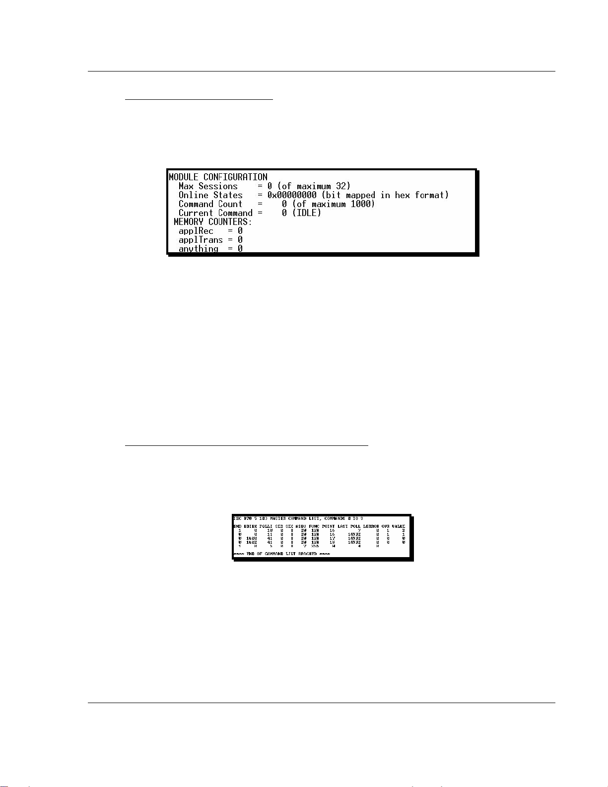
Diagnostics and Troubleshooting MVI46-103M ♦ SLC Platform
IEC 60870-5-103 Master Communication Module
Viewing General Configuration
Press [C] from the IEC-103 Master Driver Menu to display the general
configuration for the protocol. The following illustration shows an example of the
Module Configuration screen:
The Busy/Idle message indicates the current activity state of the module. "Idle"
means it is waiting to execute a command. "Busy" means it is executing a
command and is waiting for the response to the request. This does not include
the normal class 1 and 2 polls as these are automatically generated.
The counter data displays the number of memory areas allocated for the
application layer. When no packets are pending, the counts should all be 0. If
messages are waiting to be sent, the applRec count will indicate the number
waiting to be sent. If many messages are received at the same time, the applRec
count will indicate the number of packets that must be processed. The "anything"
count indicates any other buffer area that is allocated and must be processed by
the application.
Opening the IEC-870-Master Command List Menu
Press [I] from the IEC-103 Master Driver Menu to open the ICE-870 Master
Command List menu. Use this command to view the configured command list for
the module.
For more information about the commands on this menu, refer to IEC-870-
Master Command List Menu (on page 60).
ProSoft Technology, Inc. Page 57 of 187
September 12, 2006
Page 58
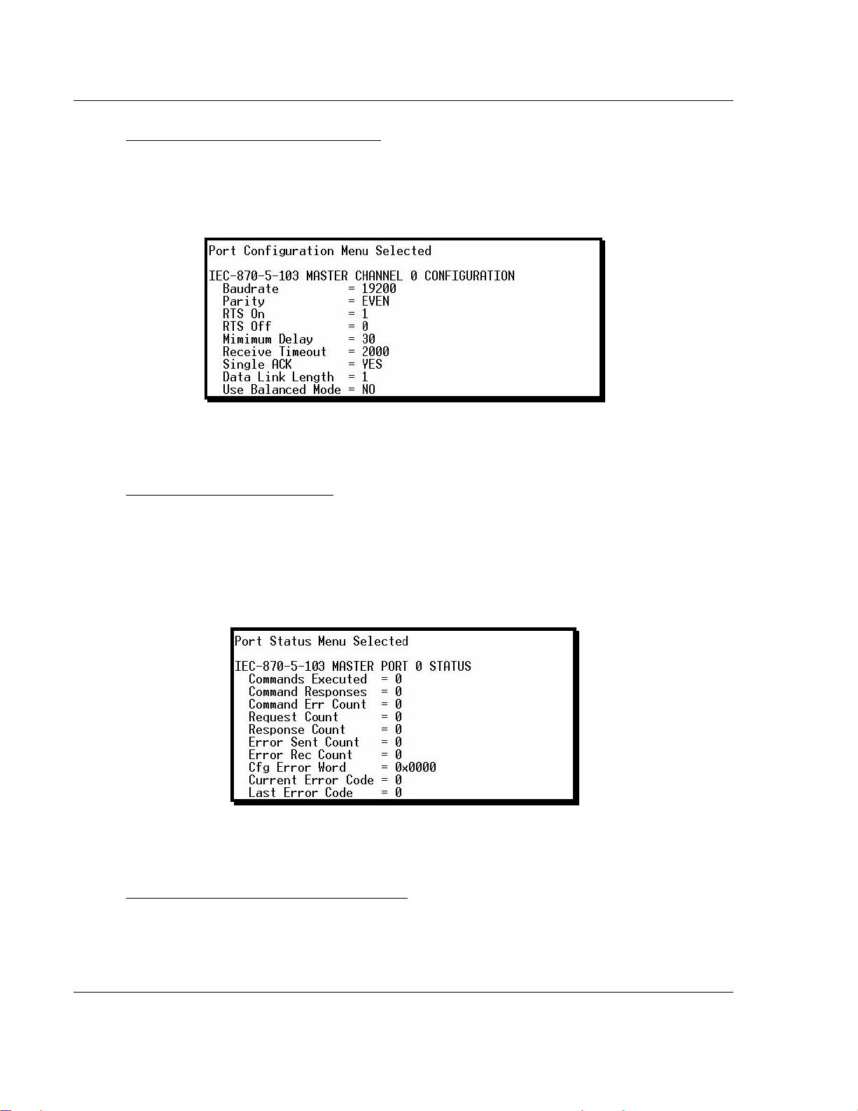
MVI46-103M ♦ SLC Platform Diagnostics and Troubleshooting
IEC 60870-5-103 Master Communication Module
Opening the Port Configuration Menu
Press [P] from the IEC-103 Master Driver Menu to open the Port Configuration
menu. Use this command to view the port configuration information for each of
the application ports.
The Port Configuration Menu section has more information about the commands
on this menu.
Opening the Port Status Menu
Press [Q] from the IEC-103 Master Driver Menu to open the Port Status menu.
Use this command to verify the status of the master commands sent through the
port. If the display indicates a communication error, you should compare the
generated error code with the command error codes listed in the Appendices of
this manual.
The Port Status Menu section has more information about the commands on this
menu.
Opening the Session Configuration Menu
Press [S] to open the Session Configuration menu. Use this command to view
the session configuration data.
Page 58 of 187 ProSoft Technology, Inc.
September 12, 2006
Page 59

Diagnostics and Troubleshooting MVI46-103M ♦ SLC Platform
IEC 60870-5-103 Master Communication Module
Refer to Session Configuration Menu (on page 66) for more information about
the commands on this menu.
Opening the Sector Menu
Press [1] from the IEC-103 Master Driver Menu to open the Sector Configuration
menu. Use this command to view the Sector Configuration data.
The Sector Configuration Menu section has more information about the
commands on this menu.
Viewing Master Driver Version Information
Press [V] from the IEC-103 Master Driver Menu to view the master driver version
information.
Returning to the Main Menu
Press [M] to return to the Main Menu.
ProSoft Technology, Inc. Page 59 of 187
September 12, 2006
Page 60
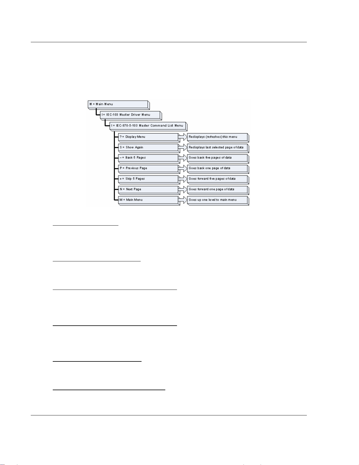
MVI46-103M ♦ SLC Platform Diagnostics and Troubleshooting
IEC 60870-5-103 Master Communication Module
6.4.4 IEC-870-Master Command List Menu
Press [I] from the IEC-103 Master Driver Menu to open the ICE-870 Master
Command List menu. Use this command to view the configured command list for
the module.
Redisplaying the Menu
Press [?] to display the current menu. Use this command when you are looking
at a screen of data, and want to view the menu choices available to you.
Redisplaying the Current Page
Press [S] to display the current page of data.
Moving Back Through 5 Pages of Registers
Press [-] from the Database View menu to skip back to the previous 500
registers of data.
Viewing the Previous 100 Registers of Data
Press [P] from the Database View menu to display the previous 100 registers of
data.
Skipping 500 Registers of Data
Hold down [Shift] and press [=] to skip forward to the next 500 registers of data.
Viewing the Next 100 Registers of Data
Press [N] from the Database View menu to select and display the next 100
registers of data.
Page 60 of 187 ProSoft Technology, Inc.
September 12, 2006
Page 61
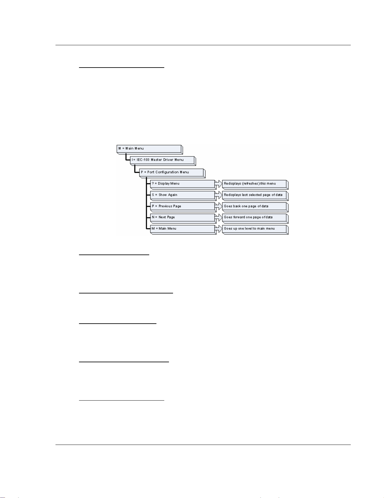
Diagnostics and Troubleshooting MVI46-103M ♦ SLC Platform
IEC 60870-5-103 Master Communication Module
Returning to the Main Menu
Press [M] to return to the Main Menu.
6.4.5 Port Configuration Menu
Press [P] from the IEC-103 Master Driver Menu to open the Port Configuration
menu. Use this command to view the port configuration information for each of
the application ports.
Redisplaying the Menu
Press [?] to display the current menu. Use this command when you are looking
at a screen of data, and want to view the menu choices available to you.
Redisplaying the Current Page
Press [S] to display the current page of data.
Displaying the Next Page
Press [N] to display the next 100 registers. Use this command to step forward
through the data a page at a time.
Displaying the Previous Page
Press [P] to display the previous 100 registers. Use this command to step
backward through the data a page at a time.
Returning to the Main Menu
Press [M] to return to the Main Menu.
ProSoft Technology, Inc. Page 61 of 187
September 12, 2006
Page 62
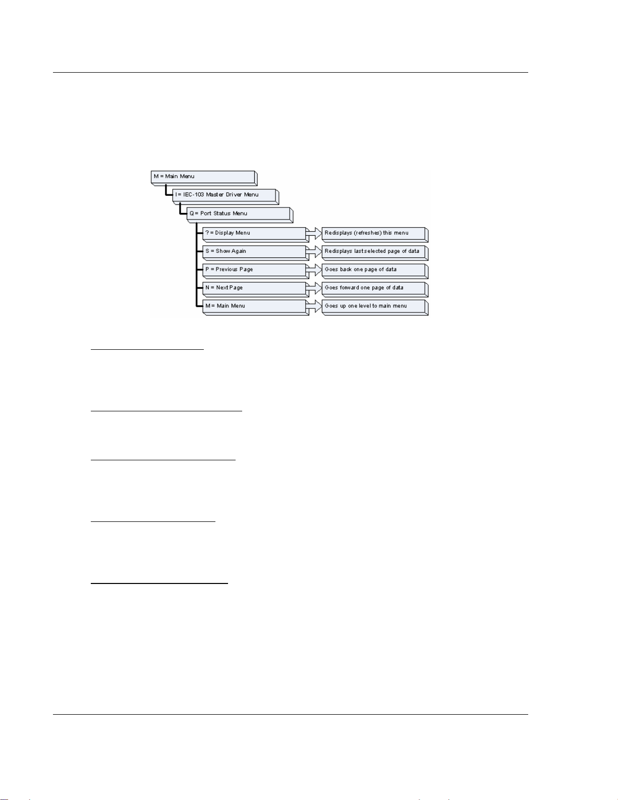
MVI46-103M ♦ SLC Platform Diagnostics and Troubleshooting
IEC 60870-5-103 Master Communication Module
6.4.6 Port Status Menu
Press [Q] from the IEC-103 Master Driver Menu to open the Port Status menu.
Use this command to view the communication status information for each
application port.
Redisplaying the Menu
Press [?] to display the current menu. Use this command when you are looking
at a screen of data, and want to view the menu choices available to you.
Redisplaying the Current Page
Press [S] to display the current page of data.
Displaying the Previous Page
Press [P] to display the previous 100 registers. Use this command to step
backward through the data a page at a time.
Displaying the Next Page
Press [N] to display the next 100 registers. Use this command to step forward
through the data a page at a time.
Returning to the Main Menu
Press [M] to return to the Main Menu.
Page 62 of 187 ProSoft Technology, Inc.
September 12, 2006
Page 63
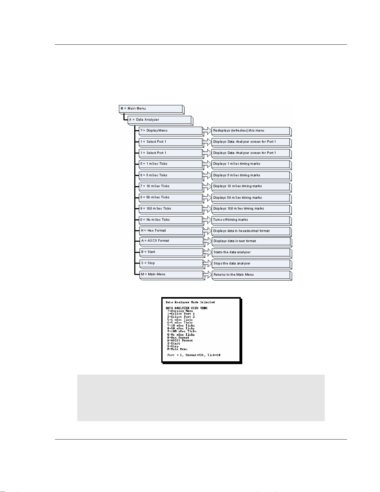
Diagnostics and Troubleshooting MVI46-103M ♦ SLC Platform
IEC 60870-5-103 Master Communication Module
6.4.7 Data Analyzer
The data analyzer mode allows you to view all bytes of data transferred on each
port. Both the transmitted and received data bytes are displayed. Use of this
feature is limited without a thorough understanding of the protocol.
Important: When in analyzer mode, program execution will slow down. Only
use this tool during a trouble-shooting session. Before disconnecting from the
Config/Debug port, please be sure to press [M] to return to the main menu and
disable the data analyzer. This action will allow the module to resume its
normal operating mode.
ProSoft Technology, Inc. Page 63 of 187
September 12, 2006
Page 64

MVI46-103M ♦ SLC Platform Diagnostics and Troubleshooting
IEC 60870-5-103 Master Communication Module
Analyzing Data for Port 1
Press [1] to display I/O data for Port 1 in the Data Analyzer. The following
illustration shows an example of the Data Analyzer output.
Analyzing Data for Port 2
Press [2] to display I/O data for Port 2 in the Data Analyzer.
Displaying Timing Marks in the Data Analyzer
You can display timing marks for a variety of intervals in the data analyzer
screen. These timing marks can help you determine communication-timing
characteristics.
Key Interval
[5] 1 mSec ticks
[6] 5 mSec ticks
[7] 10 mSec ticks
[8] 50 mSec ticks
[9] 100 mSec ticks
Removing Timing Marks in the Data Analyzer
Press [0] to turn off timing marks in the Data Analyzer screen.
Viewing Data in Hexadecimal Format
Press [H] to display the data on the current page in hexadecimal format.
Viewing Data in ASCII (Text) Format
Press [A] to display the data on the current page in ASCII format. This is useful
for regions of the database that contain ASCII data.
Page 64 of 187 ProSoft Technology, Inc.
September 12, 2006
Page 65
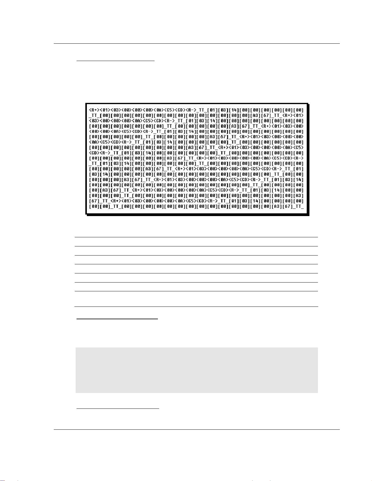
Diagnostics and Troubleshooting MVI46-103M ♦ SLC Platform
IEC 60870-5-103 Master Communication Module
Starting the Data Analyzer
Press [B] to start the data analyzer. After the key is pressed, all data transmitted
and received on the currently selected port will be displayed. An example display
is shown below:
The Data Analyzer displays the following special characters:
Character Definition
[ ] Data enclosed in these characters represent data received on the port.
< > Data enclosed in these characters represent data transmitted on the port.
<R+> These characters are inserted when the RTS line is driven high on the port.
<R-> These characters are inserted when the RTS line is dropped low on the port.
<CS> These characters are displayed when the CTS line is recognized high.
_TT_
These characters are displayed when the timing mark interval has been reached.
This parameter is user defined.
Stopping the Data Analyzer
Press [S] to stop the data analyzer. Use this option to freeze the display so the
data can be analyzed. To restart the analyzer, press [B].
Important: When in analyzer mode, program execution will slow down. Only
use this tool during a trouble-shooting session. Before disconnecting from the
Config/Debug port, please be sure to press [S] to stop the Data Analyzer
before returning to the main menu or disconnecting from the port. This action
will allow the module to resume its normal operating mode.
Returning to the Main Menu
Press [M] to return to the Main Menu.
ProSoft Technology, Inc. Page 65 of 187
September 12, 2006
Page 66

MVI46-103M ♦ SLC Platform Diagnostics and Troubleshooting
IEC 60870-5-103 Master Communication Module
6.4.8 Session Configuration Menu
Press [S] from the IEC-103 Master Driver Menu to open the Session
Configuration menu. Use this command to view the session configuration for
each controlled device.
Online State
The Online State indicator displays 0 if the module is not online, 1 if the module
is online.
Session State
The Session State indicator displays 1 if there is a configuration error, or 2 if the
module is ready for communication. If the session is not in use, the Session State
indicator displays 0.
Page 66 of 187 ProSoft Technology, Inc.
September 12, 2006
Page 67

Diagnostics and Troubleshooting MVI46-103M ♦ SLC Platform
IEC 60870-5-103 Master Communication Module
6.4.9 Sector Configuration Menu
Press [1] from the IEC-103 Master Driver Menu to open the Sector Configuration
menu. Use this command to view the contents of the Sector Configuration
Databases for each session (controlled device). The module supports up to three
sectors (databases) per session.
Redisplaying the Menu
Press [?] to display the current menu. Use this command when you are looking
at a screen of data, and want to view the menu choices available to you.
Opening the Sector Database Menu
Press [D] from the Sector Configuration menu to open the Sector Database
menu. Use this command to check the configuration and current value for each
point.
The IEC-870-Master Command List Menu section has more information about
the commands on this menu.
ProSoft Technology, Inc. Page 67 of 187
September 12, 2006
Page 68

MVI46-103M ♦ SLC Platform Diagnostics and Troubleshooting
IEC 60870-5-103 Master Communication Module
Redisplaying the Current Page
Press [S] to display the current page of data.
Displaying the Next Page
Press [N] to display the next 100 registers. Use this command to step forward
through the data a page at a time.
Displaying the Previous Page
Press [P] to display the previous 100 registers. Use this command to step
backward through the data a page at a time.
Returning to the Main Menu
Press [M] to return to the Main Menu.
6.4.10 Sector Database Menu
Press [D] from the Sector Configuration menu to open the Sector Database
menu. Use this command to display the sector database values. Each session
(controlled device) contains one or more data sets (sectors) that are defined by
the vendor of the device.
Page 68 of 187 ProSoft Technology, Inc.
September 12, 2006
Page 69
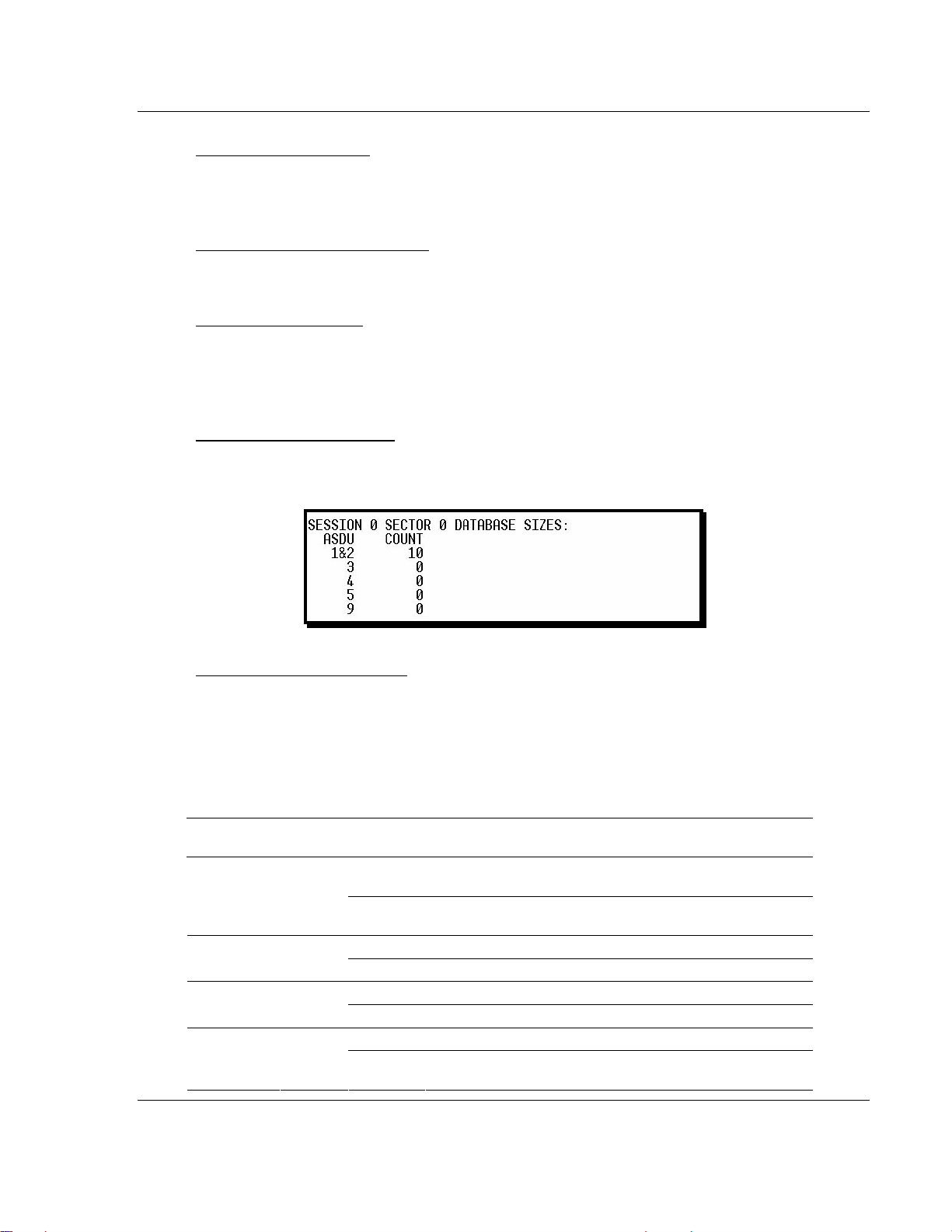
Diagnostics and Troubleshooting MVI46-103M ♦ SLC Platform
IEC 60870-5-103 Master Communication Module
Redisplaying the Menu
Press [?] to display the current menu. Use this command when you are looking
at a screen of data, and want to view the menu choices available to you.
Redisplaying the Current Page
Press [S] to display the current page of data.
Viewing ASDU n Data
Press keys [0] (zero) through [4] to display ASDU (Application Data Service Unit)
data for each of the supported data types. Refer to [IEC-103 Master Session x
Sector x] for a list of ASDU types. Listing ASDU point counts
Press [5] to display the ASDU point counts for each ASDU type.
Returning to the Main Menu
Press [M] to return to the Main Menu.
6.5 LED Status Indicators
The LEDs indicate the module's operating status as follows:
ProSoft
Module
P1 Green
Color Status Indication
On
Off
On Data being transferred on the first application port P2 Green
Off No data being transferred on port
On Data being transferred on the second application port P3 Green
Off No data being transferred on port
Off The MVI46-103M is working normally. APP Status Amber
On
Data is being transferred between the module and a
remote terminal using the Configuration/Debug port.
No data is being transferred on the Configuration/Debug
port.
The MVI46-103M module program has recognized a
communication error.
ProSoft Technology, Inc. Page 69 of 187
September 12, 2006
Page 70

MVI46-103M ♦ SLC Platform Diagnostics and Troubleshooting
IEC 60870-5-103 Master Communication Module
ProSoft
Module
BP ACT Amber
OK
Color Status Indication
The LED is on when the module is performing a write
operation on the backplane.
The LED is off when the module is performing a read
operation on the backplane. Under normal operation, the
LED should blink rapidly on and off.
The card is not receiving any power and is not securely
plugged into the rack.
The program has detected an error or is being configured.
If the LED remains red for over 10 seconds, the program
has probably halted. Remove the card from the rack and
re-insert the card to restart the module's program.
The battery voltage is low or the battery is not present.
Replace the battery on the module.
Red/
Green
On
Off
Off
Green The module is operating normally.
Red
Off The battery voltage is OK and functioning. BAT Red
On
6.5.1 Clearing a Fault Condition
Typically, if the ACT/FAULT LED on the front of the module becomes illuminated
red for over ten seconds, a hardware problem has been detected in the module
or the program has exited. To attempt to clear the condition:
1 Turn the power to the rack off
2 Remove the card from the rack
3 Re-insert the card in the rack and turn the power back on
4 Verify the configuration data being transferred to the module from the SLC
processor
If the module's ACT/FAULT LED does not turn green, make sure the module is
inserted completely into the rack. If this does not cure the problem, contact the
factory.
6.5.2 Troubleshooting
Use the following troubleshooting steps if you encounter problems when the
module is powered up. If these steps do not resolve your problem, please contact
ProSoft Technology Technical Support.
Problem Description Steps to take
Processor Fault
Be sure that the module is plugged into the slot that has been
configured for the MVI46-103M module. Be sure the ladder logic
has been set up correctly
Page 70 of 187 ProSoft Technology, Inc.
September 12, 2006
Page 71

Diagnostics and Troubleshooting MVI46-103M ♦ SLC Platform
IEC 60870-5-103 Master Communication Module
Problem Description Steps to take
BP ACT LED remains off or
blinks slowly
OK LED remains red
This indicates that backplane transfer operations are failing. Use
the Configuration/Debug port facility to check this. To establish
backplane communications, verify the following items:
The backplane driver is loaded in the module.
The ladder logic handles all read and write block
situations.
The module is configured in the processor.
The program has halted or a critical error has occurred. Connect
to the Configuration/Debug port to see if the module is running. If
the program has halted, remove the card from the rack, then reinsert.
ProSoft Technology, Inc. Page 71 of 187
September 12, 2006
Page 72

MVI46-103M ♦ SLC Platform Diagnostics and Troubleshooting
IEC 60870-5-103 Master Communication Module
Page 72 of 187 ProSoft Technology, Inc.
September 12, 2006
Page 73

Reference MVI46-103M ♦ SLC Platform
IEC 60870-5-103 Master Communication Module
7 Reference
In This Chapter
Cable Connections................................................................. 73
Setting Jumpers ..................................................................... 77
MVI46-103M Status Data Area ..............................................77
MVI46-103M Configuration Data Definition............................ 82
MVI46-103M Configuration File Example............................... 86
Database Form ....................................................................158
Command List Form............................................................. 160
Protocol Support .................................................................. 161
Protocol Interoperability Documentation .............................. 172
7.1 Cable Connections
The application ports on the MVI46-103M module support RS-232, RS-422, and
RS-485 interfaces. Please check the module to ensure that the jumpers are set
correctly to correspond with the type of interface you are using.
Note: When using RS-232 with radio modem applications, the module requires
hardware handshaking.
ProSoft Technology, Inc. Page 73 of 187
September 12, 2006
Page 74
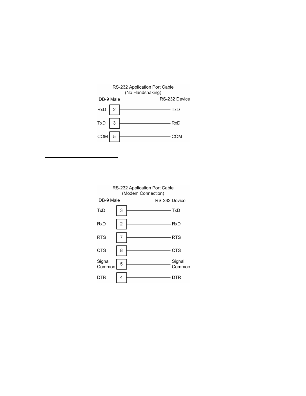
MVI46-103M ♦ SLC Platform Reference
IEC 60870-5-103 Master Communication Module
7.1.1 RS-232
When the RS-232 interface is selected, the use of the modem control lines is
user definable. If no modem control lines will be used, the cable to connect to the
port is as shown below:
RS-232 -- Modem Connection
This type of connection is required between the module and a modem or other
communication device.
The "Use CTS Line" parameter for the port configuration should be set to 'Y' for
most modem applications.
Page 74 of 187 ProSoft Technology, Inc.
September 12, 2006
Page 75
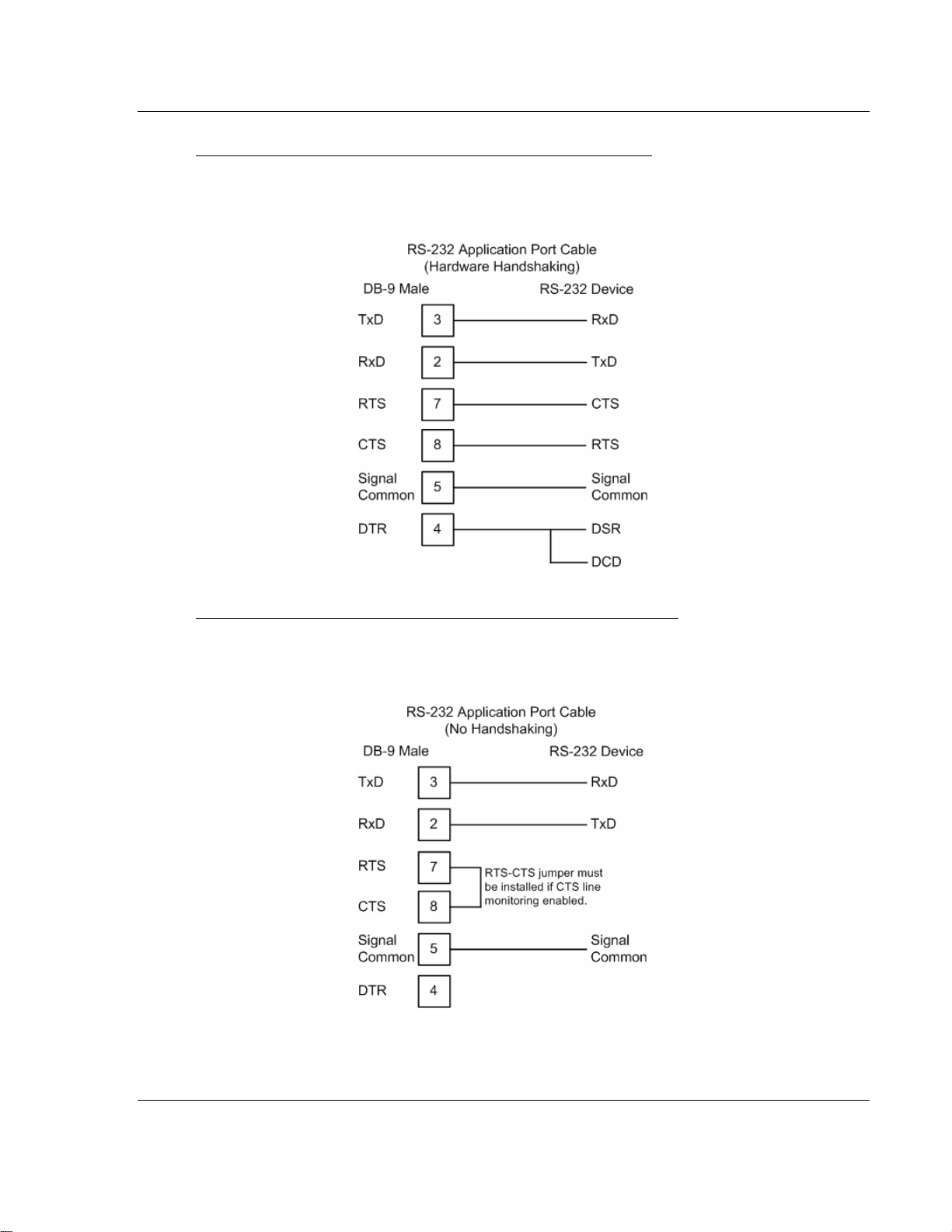
Reference MVI46-103M ♦ SLC Platform
IEC 60870-5-103 Master Communication Module
RS-232 -- Null Modem Connection (Hardware Handshaking)
This type of connection is used when the device connected to the module
requires hardware handshaking (control and monitoring of modem signal lines).
RS-232 -- Null Modem Connection (No Hardware Handshaking)
This type of connection can be used to connect the module to a computer or field
device communication port.
NOTE: If the port is configured with the "Use CTS Line" set to 'Y', then a jumper
is required between the RTS and the CTS line on the module connection.
ProSoft Technology, Inc. Page 75 of 187
September 12, 2006
Page 76

MVI46-103M ♦ SLC Platform Reference
IEC 60870-5-103 Master Communication Module
7.1.2 RS-232 Configuration/Debug Port
This port is physically an RJ45 connection. An RJ45 to DB-9 adapter cable is
included with the module. This port permits a PC based terminal emulation
program to view configuration and status data in the module and to control the
module. The cable for communications on this port is shown in the following
diagram:
7.1.3 RS-485
The RS-485 interface requires a single two or three wire cable. The ground
connection is optional and dependent on the RS-485 network. The cable required
for this interface is shown below:
Page 76 of 187 ProSoft Technology, Inc.
September 12, 2006
Page 77
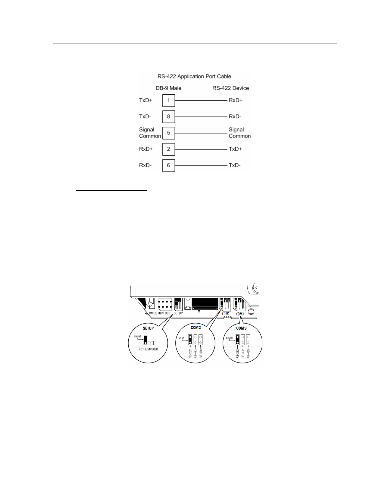
Reference MVI46-103M ♦ SLC Platform
IEC 60870-5-103 Master Communication Module
7.1.4 RS-422
RS-485 and RS-422 Tip
If communication in the RS-422/RS-485 mode does not work at first, despite all
attempts, try switching termination polarities. Some manufacturers interpret +/and A/B polarities differently.
7.2 Setting Jumpers
If you use an interface other than RS-232 (default), you must change the jumper
configuration to match the interface. The following illustration shows the MVI46103M jumper configuration:
ProSoft Technology, Inc. Page 77 of 187
September 12, 2006
Page 78

MVI46-103M ♦ SLC Platform Reference
IEC 60870-5-103 Master Communication Module
7.3 MVI46-103M Status Data Area
This section contains a listing of the data contained in the MVI46-103M status
data object, configuration error word and module error codes.
7.3.1 MVI46-IEC 60870-5-103 Master Communication
Module Error/Status Data Format
Offset Parameter Description
4000 Scan Count
4001 to
4002
4003 to
4004
4005 to
4006
4007 to
4008
4009 Read Blk Cnt
4010 Write Blk Cnt
4011 Parse Blk Cnt
4012 Error Blk Cnt This word contains the total number of block transfer errors.
4013 Event Msg Cnt
4014
4015 Session Count This word contains the number of session configured in the module.
4016 Current Cmd
4017 Cmd Busy Flag
4018 Cmd Count
4019 Cmd Delay
4020 Cmd Queue
Product Name
Revision
Op Sys #
Run Number This two-word data area contains the text values for the run number.
Event Msg
Overflow
This status value contains a counter incremented on each scan of the
module's main loop.
This two-word data area contains the text values representing the
product name. These words contain the text 'I3M4' for the MVI46
platform.
This two-word data area contains the text values for the revision
number.
This two-word data area contains the text values for the operating
system number.
This word contains the total number of block read operations
successfully executed.
This word contains the total number of block write operations
successfully executed.
This word contains the total number of write blocks successfully
parsed.
This word contains the number of event messages waiting to send to
the processor.
This word contains a value of 0 if the event message buffer has not
overflowed. If the event buffer overflows, this word will be set to a value
of 1.
This word contains the index of the current command being executed
in the command list.
This word is set to zero if no command is currently being executed and
waiting on a response. If the word is set to 1, a command is currently
executing.
This word contains the count of the number of commands configured
for the module.
This word contains the command delay counter preset. There is a fixed
delay between each command to permit the module to perform class
polls on controlled stations.
This word is set to zero if the command executing is from the
command list. If the executing command is from the command queue,
the word will be set to 1.
Page 78 of 187 ProSoft Technology, Inc.
September 12, 2006
Page 79

Reference MVI46-103M ♦ SLC Platform
IEC 60870-5-103 Master Communication Module
Offset Parameter Description
4021
4022 to
4023
4024 CH 0 State This word contains the state machine value for channel 0.
4025 Cmd Req
4026 Cmd Resp
4027 Cmd Err
4028 Requests
4029 Responses
4030 Err Sent This word contains the number of error messages sent on channel 0.
4031 Err Received
4032 Cfg Err
4033 Current Error
4034 Last Error
4035 CH 1 State This word contains the state machine value for channel 1.
4036 Cmd Req
4037 Cmd Resp
4038 Cmd Err
4039 Requests
4040 Responses
4041 Err Sent This word contains the number of error messages sent on channel 1.
4042 Err Received
4043 Cfg Err
4044 Current Error
Cmd Queue
Count
Online Status
This word contains the number of active commands in the command
queue for the module. Up to 100 commands can be buffered in this
queue. These commands are transferred from the processor to the
module using special command blocks.
This double word value contains a bit for each of the 32 potential
sessions in the module. If the bit is set for a session in the double
word, the station is online. If the bit is clear, the station is offline. Use
this value to determine if commands sent from the processor will have
a chance of succeeding.
This word contains the number of commands transferred out channel
0.
This word contains the number of command response messages
received on channel 0.
This word contains the number of command errors recognized on
channel 0.
This word contains the total number of messages transmitted on
channel 0.
This word contains the total number of messages received on channel
0.
This word contains the number of error messages received on channel
0.
This bit mapped word recognizes any configuration errors for channel
0. Refer to the configuration error word table for a definition of each bit.
This word contains the error code for the current command executing
on channel 0.
This word contains the error code for the last error recognized on
channel 0.
This word contains the number of commands transferred out channel
1.
This word contains the number of command response messages
received on channel 1.
This word contains the number of command errors recognized on
channel 1.
This word contains the total number of messages transmitted on
channel 1.
This word contains the total number of messages received on channel
1.
This word contains the number of error messages received on channel
1.
This bit mapped word recognizes any configuration errors for channel
1. Refer to the configuration error word table for a definition of each bit.
This word contains the error code for the current command executing
on channel 1.
ProSoft Technology, Inc. Page 79 of 187
September 12, 2006
Page 80

MVI46-103M ♦ SLC Platform Reference
IEC 60870-5-103 Master Communication Module
Offset Parameter Description
4045 Last Error
This word contains the error code for the last error recognized on
channel 1.
The following table defines the contents of the configuration error word. Each bit
in the word corresponds to an error condition recognized when the module is
configured. There is a separate word for each application port. This data is
reported in the status data area previously defined.
Bit Code Description
0 0x0001 Invalid baud rate selected
1 0x0002 Invalid parity selected
2 0x0004 Received timeout set to 0
3 0x0008 Invalid Port selected for a session
4 0x0010 Invalid sector count for session
5 0x0020 Could not allocate memory for sector of a session.
6 0x0040
7 0x0080 Invalid failure delay or confirm timeout for session.
8 0x0100
9 0x0200
10 0x0400
11 0x0800
12 0x1000
13 0x2000
14 0x4000
15 0x8000
The following table lists all potential errors that can be generated by the IEC
60870-5-103 Master driver:
7.3.2 MVI46-IEC 60870-5-103 Master Communication
Module Error Codes
Error Description
51 Physical layer error - Error transmitting message
52 Physical layer error - Intercharacter timeout occurred before message fully received.
53 Physical layer error - Frame not entirely received before timeout condition.
54 Physical layer error - Invalid frame length.
101 Link layer error - Invalid checksum received
102 Link layer error - Address unknown to module
103 Link layer error - Link established
104 Link layer error - Link failed
105 Link layer error - Received primary
106 Link layer error - FCB error discard
Page 80 of 187 ProSoft Technology, Inc.
September 12, 2006
Page 81

Reference MVI46-103M ♦ SLC Platform
IEC 60870-5-103 Master Communication Module
Error Description
107 Link layer error - FCB error repeat
108 Link layer error - Invalid start character received
109 Link layer error - Invalid second character received
110 Link layer error - Invalid ending character received
111 Link layer error - Length mismatch error
112 Link layer error - Illegal function
113 Link layer error - No confirmation received
114 Link layer error - No ACK received
115 Link layer error - Sequence unknown
116 Link layer error - Out of sequence
117 Link layer error - Remote close
118 Link layer error - Unexpected ACK
119 Link layer error - Request cancelled
201 Application layer error - Length mismatch
202 Application layer error - Address unknown
203 Application layer error - Response late
251 RBE error - Clock event buffer overflow
252 RBE error - Event buffer overflow
271 Data error - Address unknown
281 Control error - Illegal operation
282 Control error - Illegal value
283 Control error - Not selected
301 Initialization error - Database
302 Initialization error - Out of memory
401 Channel open error
501 Session error - Database
502 Session error - Configuration
601 No memory to receive message
602 Session not reserved
603 Illegal session
604 Session is reserved
605 Session is not available
701 No memory to transmit message
702 ASDU not supported
703 Duplicate request
704 Illegal sector
705 Control mode is illegal
801 Partial stop request
802 Stop request failed
901 Response timeout
ProSoft Technology, Inc. Page 81 of 187
September 12, 2006
Page 82

MVI46-103M ♦ SLC Platform Reference
IEC 60870-5-103 Master Communication Module
Error Description
902 Negative COT in response
903 Session is offline
904 Session is disabled
905 Select confirmation received, waiting to execute
906 Execute confirmation has not be received
7.4 MVI46-103M Configuration Data Definition
This section contains a listing of the parameters and their definitions for the
MVI46-103M module configuration file definition (IEC103M.CFG).
7.4.1 MVI46 IEC 60870-5-103 Master Communication
Module Configuration
[Section]/Item Value Range Description
[Backplane Configuration] Backplane transfer parameters
Module Name:
0 to 80
characters
Failure Flag Count: 0 to 65535
Pass-Through Events: Y or N
This parameter assigns a name to the
module that can be viewed using the
configuration/debug port. It can be used to
identify the module and the configuration
file.
This parameter specifies the number of
successive transfer errors that must occur
before the communication ports are shut
down. If the parameter is set to 0, the
communication ports will continue to
operate under all conditions. If the value is
set larger than 0 (1-65535),
communications will cease if the specified
number of failures occur.
This parameter specifies if event messages
received on the master ports will be passed
to the processor. If the parameter is set to
N, event messages will not be passed to
the processor. If the parameter is set to Y,
the module will pass all events received to
the processor using block identifier 9903.
[Section]/Item Value Range Description
[IEC 60870-5-103 MASTER] Module level parameters
Session Count: 1 to 32
This parameter specifies the maximum
number of session to establish on the
module. This corresponds to the number of
slaves to be interfaced with the module.
This value represents the total number of
slaves on both ports combined.
Page 82 of 187 ProSoft Technology, Inc.
September 12, 2006
Page 83

Reference MVI46-103M ♦ SLC Platform
IEC 60870-5-103 Master Communication Module
[Section]/Item Value Range Description
[IEC 60870-5-103 MASTER PORT
x]
Baud Rate:
Parity:
RTS On: 0 to 65535
RTS Off: 1 to 65535
Minimum Delay: 1 to 60000
Receive Timeout: 1 to 65535
Single char ACK F0,1 or 3: Y or N
Value for
baud rate
None, Odd,
Even
Settings for each communication port on
module
This parameter specifies the baud rate to
be used on the communication channel
(port). Values from 110 to 19200K are
permitted.
This parameter sets the parity to be used
on the port. The values correspond to the
following settings: None, Odd, Even.
NOTE: the specification only utilizes Even
Parity.
The parameter sets the RTS presend
delay. The value entered represents the
number of milliseconds the module will wait
after setting the RTS modem line before
sending the data.
This parameter sets the RTS off delay. The
value entered represents the number of
milliseconds the module will wait after the
data packet is sent before dropping the
RTS modem line.
This parameter specifies the minimum
number of milliseconds to delay before
sending the message (setting RTS high).
This can be used when the serial network
requires time for units to turn off their
transmitters.
This value represents the number of
milliseconds to wait on a port from the time
the first character is received until the last
character in the longest message received
on the port. This parameter should be set
dependent on the baud rate. A value of
2000 should work with most applications.
This parameter specifies if the single E5
character will be used for ACK messages.
[Section]/Item Value Range Description
[IEC-103 MASTER SESSION x] Settings for each session utilized
Communication Port: 0 or 1
Sector Count: 1 to 5
This parameter sets the port to which the
controlled device is connected. On this
module, values of 0 and 1 are permitted.
This parameter sets the number of sectors
contained in this controlled device. This
version of the application supports 1 to 5
sectors for each session.
ProSoft Technology, Inc. Page 83 of 187
September 12, 2006
Page 84

MVI46-103M ♦ SLC Platform Reference
IEC 60870-5-103 Master Communication Module
[Section]/Item Value Range Description
Data Link Address: 0 to 254
Failure Delay: 0 to 2000
Confirm Timeout: 0 to 2^32–1
Retry Count: 0 to 255
C1/C2 Poll Count Pend: 0 to 100
Class 1 Polls: 0 to 65535
Class 1 Pend Delay: 0 to 2^32–1
Class 2 Pend Delay: 0 to 2^32–1
Class 1 Poll Delay: 0 to 2^32–1
Class 2 Poll Delay: 0 to 2^32–1
Response Timeout: 0 to 2^32–1
This parameter uniquely defines the data
link address for this unit on the
communication channel The ranges of
values are from 0 to 254. Address 255 is
the broadcast address.
This parameter sets the minimum number
of seconds to delay before polling this
session when it is not online. This
parameter is only used in unbalanced
mode.
This parameter sets the number of
milliseconds to wait for a confirm response
from the controlled device.
This parameter sets the number of retries
to be performed on the controlled device
when a communication error occurs.
This parameter sets the maximum number
of class 1 and class 2 polls performed on
this session before trying the next session.
This parameter prevents a session from
monopolizing the communication port.
This parameter sets the maximum number
of class one polls performed on this
session before switching to another
session. This parameter prevents a session
from monopolizing the communication port.
This parameter sets the minimum number
of milliseconds to delay between class 1
polls for pending data.
This parameter sets the minimum number
of milliseconds to delay between class 2
polls for pending data.
This parameter sets the minimum number
of milliseconds to delay between each
class 1 poll.
This parameter sets the minimum number
of milliseconds to delay between each
class 2 poll.
This parameter sets the maximum number
of milliseconds to wait for a confirmation
from the controlled station to a request
from this module.
[Section]/Item Value Range Description
[IEC-103 MASTER SESSION x
SECTOR y]
This section sets the parameters for a
specific sector of a session.
Page 84 of 187 ProSoft Technology, Inc.
September 12, 2006
Page 85

Reference MVI46-103M ♦ SLC Platform
IEC 60870-5-103 Master Communication Module
[Section]/Item Value Range Description
Common ASDU Address: 0 to 255
Online Time Sync: Y or N
Online General Int: Y or N
EOI Time Sync: Y or N
EOI General Int: Y or N
# ASDU Point Function Database
# Type Index Code Point
START
END
This parameter sets the common ASDU
address to association with this sector of
the specified session. This parameter is
usually set the same as the data link
address when only one sector is utilized.
This parameter specifies if the sector in the
controlled device will be sent a time
synchronization command when the unit is
first recognized as being online. This
should only be utilized for devices that do
not send an EOI message after initializing.
This parameter specifies if the sector in the
controlled device will be sent a general
interrogation command when the unit is
first recognized as being online. This
should only be utilized for devices that do
not send an EOI message after initializing.
This parameter specifies if the sector in the
controlled device will be sent a time
synchronization command after this module
received an EOI message from the
controlled unit.
This parameter specifies if the sector in the
controlled device will be sent a general
interrogation command after this module
received an EOI message from the
controlled unit.
[Section]/Item Description
[IEC-103 MASTER COMMANDS]
# Enable DB Poll Session Sector Data Func Point Ovrd Ovrd
# Code Index Interval Index Index Type Code Index Flag Val
START
END
This section contains the commands for the
module
Please refer to the Module Configuration section for command field definitions.
ProSoft Technology, Inc. Page 85 of 187
September 12, 2006
Page 86

MVI46-103M ♦ SLC Platform Reference
IEC 60870-5-103 Master Communication Module
7.5 MVI46-103M Configuration File Example
This section contains a listing of an example IEC103M.CFG file for the MVI46103M module.
# IEC103M.CFG
#
# Example file for use with the IEC-870-5-103 Master protocol driver on the
# MVI46 platform (two master ports).
#
[Backplane Configuration]
Module Name : MVI46-103M DEMO MODULE
Failure Flag Count : 0 #Determines if BP failure will cause protocol to be
#disabled (0=Ignore, >0 = failure count to disable)
Pass-Through Events : Y #Pass event messages to processor
# This is the configuration for the IEC-870-5-103 master port emulated on the
# module.
[IEC-870-5-103 Master]
Session Count : 1 #1 to 32 - maximum number of slaves on all channels
[IEC-870-5-103 Master Port 0]
# Communication Parameters
Baud Rate : 19200 #Baud rate for port 110-115200
Parity : E #N=None, O=Odd, E=Even, M=Mark, S=Space
RTS On : 0 #0-65536 mSec before message
RTS Off : 0 #0-65536 mSec after message
Minimum Delay : 10 #Minimum # of mSec before response sent
Receive Timeout : 2000 #Maximum mSec from first char to last to wait
# These parameters are protocol specific
Single char ACK F0,1 or 3 : Y #Single E5 resp to ACK func 0, 1 & 3 req (Y/N)
[IEC-870-5-103 Master Port 1]
# Communication Parameters
Baud Rate : 19200 #Baud rate for port 110-115200
Parity : E #N=None, O=Odd, E=Even, M=Mark, S=Space
RTS On : 0 #0-65536 mSec before message
RTS Off : 0 #0-65536 mSec after message
Minimum Delay : 5 #Minimum # of mSec before response sent
Receive Timeout : 1000 #Maximum mSec from first char to last to wait
# These parameters are protocol specific
Single char ACK F0,1 or 3 : Y #Single E5 resp to ACK func 0, 1 & 3 req (Y/N)
# This section is used to define session 0 which runs on Port 0
[IEC-103 Master Session 0]
Communication Port : 0 #Index of COM port for session (0 or 1)
Sector Count : 5 #5 is max for this version of app
Data Link Address : 0 #Range is 0 to 65535 DL address of slave
Failure Delay : 3 #Min Sec to delay before poll of offline slave
#(0 to 2000 seconds)
Page 86 of 187 ProSoft Technology, Inc.
September 12, 2006
Page 87

Reference MVI46-103M ♦ SLC Platform
IEC 60870-5-103 Master Communication Module
Confirm Timeout : 20000 #0 to 2^32-1 mSec to wait for DL confirm
Retry Count : 5 #0 to 255 retries for if no confirm
Response Timeout : 5000 #Timeout for confirm of req (0 to 2^32-1)
C1/C2 Poll Count Pend : 6 #class 1 or 2 polls before next slave tried (0-
65535)
Class 1 Polls : 10 #Max class 1 polls to this session
Class 1 Pend delay : 1000 #Min mSec delay between call (0 to 2^32-1)
Class 2 Pend delay : 1000 #Min mSec delay between call (0 to 2^32-1)
Class 1 Poll delay : 1000 #Min mSec delay between call (0 to 2^32-1)
Class 2 Poll delay : 1000 #Min mSec delay between call (0 to 2^32-1)
[IEC-103 Master Session 0 Sector 0]
Common ASDU Address : 0 #Range 0 to 255 Sector address
#Req init requests when session first online (not req if slave sends
# EOI sequence)
Online Time sync : Y #Send time sync message when first online
Online General Int : Y #Send general interrogation
#Req init requests when EOI (end of initialization) received from slave
EOI Time sync : Y #Send time sync message when first online
EOI General Int : Y #Send general interrogation
# Database definition for this session/sector
# Types are as follows:
#
# Monitored ASDU Types
# 1 = Time-tagged message (bit addressed with 2 bits/point)
# 2 = Time-tagged message with relative time (bit addressed with 2 bits/point)
# 3 = Measurands I (4 word values using word address using double-word address)
# 4 = Time-tagged measurands with relative time (1 float value)
# 5 = Identification (12 characters using a byte address)
# 9 = Measurands II (9 word values using word address)
#
# Point Index is the information object number in the slave unit.
# ASDU Index Description
# 1 Bit address with each point occupying 2 bits
# 2 Bit address with each point occupying 2 bits
# 3 Word address with each point occupying 4 words
# 4 Double-word address for the single float value
# 5 Byte address with each point occupying 12 bytes
# 9 Word address with each point occupying 9 words
#
# Function Code Values
# Code Definition
# 128 Distance protection
# 160 Overcurrent protection
# 176 Transformer differential protection
# 192 Line Differential protection
# 255 Global function type
#
# Database Index = Database address in module
#
# ASDU Database Function Point
# Type Index Code Index
ProSoft Technology, Inc. Page 87 of 187
September 12, 2006
Page 88

MVI46-103M ♦ SLC Platform Reference
IEC 60870-5-103 Master Communication Module
START
1 0 128 16
1 16 128 18
1 32 128 19
1 48 128 20
1 64 128 21
1 80 128 22
1 96 128 23
1 112 128 24
1 128 128 25
1 144 128 26
END
[IEC-103 Master Session 0 Sector 1]
Common ASDU Address : 1 #Range 0 to 255 Sector address
#Req init requests when session first online (not req if slave sends
# EOI sequence)
Online Time sync : Y #Send time sync message when first online
Online General Int : Y #Send general interrogation
#Req init requests when EOI (end of initialization) received from slave
EOI Time sync : Y #Send time sync message when first online
EOI General Int : Y #Send general interrogation
# Database definition for this session/sector
# Types are as follows:
#
# Monitored ASDU Types
# 1 = Time-tagged message (bit addressed with 2 bits/point)
# 2 = Time-tagged message with relative time (bit addressed with 2 bits/point)
# 3 = Measurands I (4 word values using word address using double-word address)
# 4 = Time-tagged measurands with relative time (1 float value)
# 5 = Identification (12 characters using a byte address)
# 9 = Measurands II (9 word values using word address)
#
# Point Index is the information object number in the slave unit.
# ASDU Index Description
# 1 Bit address with each point occupying 2 bits
# 2 Bit address with each point occupying 2 bits
# 3 Word address with each point occupying 4 words
# 4 Double-word address for the single float value
# 5 Byte address with each point occupying 12 bytes
# 9 Word address with each point occupying 9 words
#
# Function Code Values
# Code Definition
# 128 Distance protection
# 160 Overcurrent protection
# 176 Transformer differential protection
# 192 Line Differential protection
# 255 Global function type
#
# Database Index = Database address in module
#
Page 88 of 187 ProSoft Technology, Inc.
September 12, 2006
Page 89

Reference MVI46-103M ♦ SLC Platform
IEC 60870-5-103 Master Communication Module
# ASDU Database Function Point
# Type Index Code Index
START
1 160 128 27
1 176 128 28
1 192 128 29
1 208 128 30
1 224 128 32
1 240 128 33
1 256 128 35
1 272 128 36
1 288 128 37
1 304 128 38
END
[IEC-103 Master Session 0 Sector 2]
Common ASDU Address : 2 #Range 0 to 255 Sector address
#Req init requests when session first online (not req if slave sends
# EOI sequence)
Online Time sync : Y #Send time sync message when first online
Online General Int : Y #Send general interrogation
#Req init requests when EOI (end of initialization) received from slave
EOI Time sync : Y #Send time sync message when first online
EOI General Int : Y #Send general interrogation
# Database definition for this session/sector
# Types are as follows:
#
# Monitored ASDU Types
# 1 = Time-tagged message (bit addressed with 2 bits/point)
# 2 = Time-tagged message with relative time (bit addressed with 2 bits/point)
# 3 = Measurands I (4 word values using word address using double-word address)
# 4 = Time-tagged measurands with relative time (1 float value)
# 5 = Identification (12 characters using a byte address)
# 9 = Measurands II (9 word values using word address)
#
# Point Index is the information object number in the slave unit.
# ASDU Index Description
# 1 Bit address with each point occupying 2 bits
# 2 Bit address with each point occupying 2 bits
# 3 Word address with each point occupying 4 words
# 4 Double-word address for the single float value
# 5 Byte address with each point occupying 12 bytes
# 9 Word address with each point occupying 9 words
#
# Function Code Values
# Code Definition
# 128 Distance protection
# 160 Overcurrent protection
# 176 Transformer differential protection
# 192 Line Differential protection
# 255 Global function type
#
ProSoft Technology, Inc. Page 89 of 187
September 12, 2006
Page 90

MVI46-103M ♦ SLC Platform Reference
IEC 60870-5-103 Master Communication Module
# Database Index = Database address in module
#
# ASDU Database Function Point
# Type Index Code Index
START
1 320 128 39
1 336 128 46
1 352 128 47
1 368 128 48
1 384 128 49
1 400 128 50
1 416 128 51
1 432 128 52
1 448 128 128
1 464 128 129
END
[IEC-103 Master Session 0 Sector 3]
Common ASDU Address : 3 #Range 0 to 255 Sector address
#Req init requests when session first online (not req if slave sends
# EOI sequence)
Online Time sync : Y #Send time sync message when first online
Online General Int : Y #Send general interrogation
#Req init requests when EOI (end of initialization) received from slave
EOI Time sync : Y #Send time sync message when first online
EOI General Int : Y #Send general interrogation
# Database definition for this session/sector
# Types are as follows:
#
# Monitored ASDU Types
# 1 = Time-tagged message (bit addressed with 2 bits/point)
# 2 = Time-tagged message with relative time (bit addressed with 2 bits/point)
# 3 = Measurands I (4 word values using word address using double-word address)
# 4 = Time-tagged measurands with relative time (1 float value)
# 5 = Identification (12 characters using a byte address)
# 9 = Measurands II (9 word values using word address)
#
# Point Index is the information object number in the slave unit.
# ASDU Index Description
# 1 Bit address with each point occupying 2 bits
# 2 Bit address with each point occupying 2 bits
# 3 Word address with each point occupying 4 words
# 4 Double-word address for the single float value
# 5 Byte address with each point occupying 12 bytes
# 9 Word address with each point occupying 9 words
#
# Function Code Values
# Code Definition
# 128 Distance protection
# 160 Overcurrent protection
# 176 Transformer differential protection
# 192 Line Differential protection
Page 90 of 187 ProSoft Technology, Inc.
September 12, 2006
Page 91

Reference MVI46-103M ♦ SLC Platform
IEC 60870-5-103 Master Communication Module
# 255 Global function type
#
# Database Index = Database address in module
#
# ASDU Database Function Point
# Type Index Code Index
START
2 480 128 64
2 496 128 65
2 512 128 66
2 528 128 67
2 544 128 68
2 560 128 69
2 576 128 70
2 592 128 71
2 608 128 72
2 624 128 73
END
[IEC-103 Master Session 0 Sector 4]
Common ASDU Address : 4 #Range 0 to 255 Sector address
#Req init requests when session first online (not req if slave sends
# EOI sequence)
Online Time sync : Y #Send time sync message when first online
Online General Int : Y #Send general interrogation
#Req init requests when EOI (end of initialization) received from slave
EOI Time sync : Y #Send time sync message when first online
EOI General Int : Y #Send general interrogation
# Database definition for this session/sector
# Types are as follows:
#
# Monitored ASDU Types
# 1 = Time-tagged message (bit addressed with 2 bits/point)
# 2 = Time-tagged message with relative time (bit addressed with 2 bits/point)
# 3 = Measurands I (4 word values using word address using double-word address)
# 4 = Time-tagged measurands with relative time (1 float value)
# 5 = Identification (12 characters using a byte address)
# 9 = Measurands II (9 word values using word address)
#
# Point Index is the information object number in the slave unit.
# ASDU Index Description
# 1 Bit address with each point occupying 2 bits
# 2 Bit address with each point occupying 2 bits
# 3 Word address with each point occupying 4 words
# 4 Double-word address for the single float value
# 5 Byte address with each point occupying 12 bytes
# 9 Word address with each point occupying 9 words
#
# Function Code Values
# Code Definition
# 128 Distance protection
# 160 Overcurrent protection
ProSoft Technology, Inc. Page 91 of 187
September 12, 2006
Page 92

MVI46-103M ♦ SLC Platform Reference
IEC 60870-5-103 Master Communication Module
# 176 Transformer differential protection
# 192 Line Differential protection
# 255 Global function type
#
# Database Index = Database address in module
#
# ASDU Database Function Point
# Type Index Code Index
START
2 640 128 74
2 656 128 75
2 672 128 76
2 688 128 77
2 704 128 78
2 720 128 79
2 736 128 80
2 752 128 81
2 768 128 82
2 784 128 83
2 800 128 84
2 816 128 85
2 832 128 86
2 848 128 87
2 864 128 88
2 880 128 89
2 896 128 90
2 912 128 91
2 880 128 89
2 896 128 90
3 60 128 144
3 64 128 145
3 68 128 146
3 72 128 147
END
# This section is used to define session 0 which runs on Port 1
[IEC-103 Master Session 1]
Communication Port : 0 #Index of COM port for session (0 or 1)
Sector Count : 5 #1 is max value for this version of app
Data Link Address : 1 #Range is 0 to 65535 DL address of slave
Failure Delay : 10 #Min Sec to delay before poll of offline slave
#(0 to 2000 seconds)
Confirm Timeout : 1000 #0 to 2^32-1 mSec to wait for DL confirm
Retry Count : 0 #0 to 255 retries for if no confirm
Response Timeout : 20000 #Timeout for confirm of req (0 to 2^32-1)
C1/C2 Poll Count Pend : 5 #class 1 or 2 polls before next slave tried (0-
65535)
Class 1 Polls : 0 #Max class 1 polls to this session
Class 1 Pend delay : 0 #Min mSec delay between call (0 to 2^32-1)
Class 2 Pend delay : 0 #Min mSec delay between call (0 to 2^32-1)
Class 1 Poll delay : 0 #Min mSec delay between call (0 to 2^32-1)
Class 2 Poll delay : 0 #Min mSec delay between call (0 to 2^32-1)
Page 92 of 187 ProSoft Technology, Inc.
September 12, 2006
Page 93

Reference MVI46-103M ♦ SLC Platform
IEC 60870-5-103 Master Communication Module
[IEC-103 Master Session 1 Sector 0]
Common ASDU Address : 0 #Range 0 to 65534 Sector address
#Req init requests when session first online (not req if slave sends
# EOI sequence)
Online Time sync : Y #Send time sync message when first online
Online General Int : Y #Send general interrogation
#Req init requests when EOI (end of initialization) received from slave
EOI Time sync : Y #Send time sync message when first online
EOI General Int : Y #Send general interrogation
# Database definition for this session/sector
#
# ASDU Database Function Point
# Type Index Code Index
START
END
[IEC-103 Master Session 1 Sector 1]
Common ASDU Address : 1 #Range 0 to 65534 Sector address
#Req init requests when session first online (not req if slave sends
# EOI sequence)
Online Time sync : Y #Send time sync message when first online
Online General Int : Y #Send general interrogation
#Req init requests when EOI (end of initialization) received from slave
EOI Time sync : Y #Send time sync message when first online
EOI General Int : Y #Send general interrogation
# Database definition for this session/sector
#
# ASDU Database Function Point
# Type Index Code Index
START
END
[IEC-103 Master Session 1 Sector 2]
Common ASDU Address : 2 #Range 0 to 65534 Sector address
#Req init requests when session first online (not req if slave sends
# EOI sequence)
Online Time sync : Y #Send time sync message when first online
Online General Int : Y #Send general interrogation
#Req init requests when EOI (end of initialization) received from slave
EOI Time sync : Y #Send time sync message when first online
EOI General Int : Y #Send general interrogation
# Database definition for this session/sector
#
# ASDU Database Function Point
# Type Index Code Index
START
ProSoft Technology, Inc. Page 93 of 187
September 12, 2006
Page 94

MVI46-103M ♦ SLC Platform Reference
IEC 60870-5-103 Master Communication Module
END
[IEC-103 Master Session 1 Sector 3]
Common ASDU Address : 3 #Range 0 to 65534 Sector address
#Req init requests when session first online (not req if slave sends
# EOI sequence)
Online Time sync : Y #Send time sync message when first online
Online General Int : Y #Send general interrogation
#Req init requests when EOI (end of initialization) received from slave
EOI Time sync : Y #Send time sync message when first online
EOI General Int : Y #Send general interrogation
# Database definition for this session/sector
#
# ASDU Database Function Point
# Type Index Code Index
START
END
[IEC-103 Master Session 1 Sector 4]
Common ASDU Address : 4 #Range 0 to 65534 Sector address
#Req init requests when session first online (not req if slave sends
# EOI sequence)
Online Time sync : Y #Send time sync message when first online
Online General Int : Y #Send general interrogation
#Req init requests when EOI (end of initialization) received from slave
EOI Time sync : Y #Send time sync message when first online
EOI General Int : Y #Send general interrogation
# Database definition for this session/sector
#
# ASDU Database Function Point
# Type Index Code Index
START
END
# This section is used to define session 0 which runs on Port 1
[IEC-103 Master Session 2]
Communication Port : 0 #Index of COM port for session (0 or 1)
Sector Count : 5 #1 is max value for this version of app
Data Link Address : 2 #Range is 0 to 65535 DL address of slave
Failure Delay : 10 #Min Sec to delay before poll of offline slave
#(0 to 2000 seconds)
Confirm Timeout : 1000 #0 to 2^32-1 mSec to wait for DL confirm
Retry Count : 2 #0 to 255 retries for if no confirm
Response Timeout : 10000 #Timeout for confirm of req (0 to 2^32-1)
C1/C2 Poll Count Pend : 0 #class 1 or 2 polls before next slave tried (0-
65535)
Class 1 Polls : 0 #Max class 1 polls to this session
Class 1 Pend delay : 0 #Min mSec delay between call (0 to 2^32-1)
Page 94 of 187 ProSoft Technology, Inc.
September 12, 2006
Page 95

Reference MVI46-103M ♦ SLC Platform
IEC 60870-5-103 Master Communication Module
Class 2 Pend delay : 0 #Min mSec delay between call (0 to 2^32-1)
Class 1 Poll delay : 0 #Min mSec delay between call (0 to 2^32-1)
Class 2 Poll delay : 0 #Min mSec delay between call (0 to 2^32-1)
[IEC-103 Master Session 2 Sector 0]
Common ASDU Address : 0 #Range 0 to 65534 Sector address
#Req init requests when session first online (not req if slave sends
# EOI sequence)
Online Time sync : Y #Send time sync message when first online
Online General Int : Y #Send general interrogation
#Req init requests when EOI (end of initialization) received from slave
EOI Time sync : Y #Send time sync message when first online
EOI General Int : Y #Send general interrogation
# Database definition for this session/sector
#
# ASDU Database Function Point
# Type Index Code Index
START
END
[IEC-103 Master Session 2 Sector 1]
Common ASDU Address : 1 #Range 0 to 65534 Sector address
#Req init requests when session first online (not req if slave sends
# EOI sequence)
Online Time sync : Y #Send time sync message when first online
Online General Int : Y #Send general interrogation
#Req init requests when EOI (end of initialization) received from slave
EOI Time sync : Y #Send time sync message when first online
EOI General Int : Y #Send general interrogation
# Database definition for this session/sector
#
# ASDU Database Function Point
# Type Index Code Index
START
END
[IEC-103 Master Session 2 Sector 2]
Common ASDU Address : 2 #Range 0 to 65534 Sector address
#Req init requests when session first online (not req if slave sends
# EOI sequence)
Online Time sync : Y #Send time sync message when first online
Online General Int : Y #Send general interrogation
#Req init requests when EOI (end of initialization) received from slave
EOI Time sync : Y #Send time sync message when first online
EOI General Int : Y #Send general interrogation
# Database definition for this session/sector
ProSoft Technology, Inc. Page 95 of 187
September 12, 2006
Page 96

MVI46-103M ♦ SLC Platform Reference
IEC 60870-5-103 Master Communication Module
#
# ASDU Database Function Point
# Type Index Code Index
START
END
[IEC-103 Master Session 2 Sector 3]
Common ASDU Address : 3 #Range 0 to 65534 Sector address
#Req init requests when session first online (not req if slave sends
# EOI sequence)
Online Time sync : Y #Send time sync message when first online
Online General Int : Y #Send general interrogation
#Req init requests when EOI (end of initialization) received from slave
EOI Time sync : Y #Send time sync message when first online
EOI General Int : Y #Send general interrogation
# Database definition for this session/sector
#
# ASDU Database Function Point
# Type Index Code Index
START
END
[IEC-103 Master Session 2 Sector 4]
Common ASDU Address : 4 #Range 0 to 65534 Sector address
#Req init requests when session first online (not req if slave sends
# EOI sequence)
Online Time sync : Y #Send time sync message when first online
Online General Int : Y #Send general interrogation
#Req init requests when EOI (end of initialization) received from slave
EOI Time sync : Y #Send time sync message when first online
EOI General Int : Y #Send general interrogation
# Database definition for this session/sector
#
# ASDU Database Function Point
# Type Index Code Index
START
END
# This section is used to define session 0 which runs on Port 1
[IEC-103 Master Session 3]
Communication Port : 0 #Index of COM port for session (0 or 1)
Sector Count : 5 #1 is max value for this version of app
Data Link Address : 3 #Range is 0 to 65535 DL address of slave
Failure Delay : 10 #Min Sec to delay before poll of offline slave
#(0 to 2000 seconds)
Confirm Timeout : 1000 #0 to 2^32-1 mSec to wait for DL confirm
Retry Count : 2 #0 to 255 retries for if no confirm
Response Timeout : 10000 #Timeout for confirm of req (0 to 2^32-1)
Page 96 of 187 ProSoft Technology, Inc.
September 12, 2006
Page 97

Reference MVI46-103M ♦ SLC Platform
IEC 60870-5-103 Master Communication Module
C1/C2 Poll Count Pend : 0 #class 1 or 2 polls before next slave tried (0-
65535)
Class 1 Polls : 0 #Max class 1 polls to this session
Class 1 Pend delay : 0 #Min mSec delay between call (0 to 2^32-1)
Class 2 Pend delay : 0 #Min mSec delay between call (0 to 2^32-1)
Class 1 Poll delay : 0 #Min mSec delay between call (0 to 2^32-1)
Class 2 Poll delay : 0 #Min mSec delay between call (0 to 2^32-1)
[IEC-103 Master Session 3 Sector 0]
Common ASDU Address : 0 #Range 0 to 65534 Sector address
#Req init requests when session first online (not req if slave sends
# EOI sequence)
Online Time sync : Y #Send time sync message when first online
Online General Int : Y #Send general interrogation
#Req init requests when EOI (end of initialization) received from slave
EOI Time sync : Y #Send time sync message when first online
EOI General Int : Y #Send general interrogation
# Database definition for this session/sector
#
# ASDU Database Function Point
# Type Index Code Index
START
END
[IEC-103 Master Session 3 Sector 1]
Common ASDU Address : 1 #Range 0 to 65534 Sector address
#Req init requests when session first online (not req if slave sends
# EOI sequence)
Online Time sync : Y #Send time sync message when first online
Online General Int : Y #Send general interrogation
#Req init requests when EOI (end of initialization) received from slave
EOI Time sync : Y #Send time sync message when first online
EOI General Int : Y #Send general interrogation
# Database definition for this session/sector
#
# ASDU Database Function Point
# Type Index Code Index
START
END
[IEC-103 Master Session 3 Sector 2]
Common ASDU Address : 2 #Range 0 to 65534 Sector address
#Req init requests when session first online (not req if slave sends
# EOI sequence)
Online Time sync : Y #Send time sync message when first online
Online General Int : Y #Send general interrogation
#Req init requests when EOI (end of initialization) received from slave
ProSoft Technology, Inc. Page 97 of 187
September 12, 2006
Page 98

MVI46-103M ♦ SLC Platform Reference
IEC 60870-5-103 Master Communication Module
EOI Time sync : Y #Send time sync message when first online
EOI General Int : Y #Send general interrogation
# Database definition for this session/sector
#
# ASDU Database Function Point
# Type Index Code Index
START
END
[IEC-103 Master Session 3 Sector 3]
Common ASDU Address : 3 #Range 0 to 65534 Sector address
#Req init requests when session first online (not req if slave sends
# EOI sequence)
Online Time sync : Y #Send time sync message when first online
Online General Int : Y #Send general interrogation
#Req init requests when EOI (end of initialization) received from slave
EOI Time sync : Y #Send time sync message when first online
EOI General Int : Y #Send general interrogation
# Database definition for this session/sector
#
# ASDU Database Function Point
# Type Index Code Index
START
END
[IEC-103 Master Session 3 Sector 4]
Common ASDU Address : 4 #Range 0 to 65534 Sector address
#Req init requests when session first online (not req if slave sends
# EOI sequence)
Online Time sync : Y #Send time sync message when first online
Online General Int : Y #Send general interrogation
#Req init requests when EOI (end of initialization) received from slave
EOI Time sync : Y #Send time sync message when first online
EOI General Int : Y #Send general interrogation
# Database definition for this session/sector
#
# ASDU Database Function Point
# Type Index Code Index
START
END
# This section is used to define session 0 which runs on Port 1
[IEC-103 Master Session 4]
Communication Port : 0 #Index of COM port for session (0 or 1)
Sector Count : 5 #1 is max value for this version of app
Data Link Address : 4 #Range is 0 to 65535 DL address of slave
Failure Delay : 10 #Min Sec to delay before poll of offline slave
Page 98 of 187 ProSoft Technology, Inc.
September 12, 2006
Page 99

Reference MVI46-103M ♦ SLC Platform
IEC 60870-5-103 Master Communication Module
#(0 to 2000 seconds)
Confirm Timeout : 1000 #0 to 2^32-1 mSec to wait for DL confirm
Retry Count : 2 #0 to 255 retries for if no confirm
Response Timeout : 10000 #Timeout for confirm of req (0 to 2^32-1)
C1/C2 Poll Count Pend : 0 #class 1 or 2 polls before next slave tried (0-
65535)
Class 1 Polls : 0 #Max class 1 polls to this session
Class 1 Pend delay : 0 #Min mSec delay between call (0 to 2^32-1)
Class 2 Pend delay : 0 #Min mSec delay between call (0 to 2^32-1)
Class 1 Poll delay : 0 #Min mSec delay between call (0 to 2^32-1)
Class 2 Poll delay : 0 #Min mSec delay between call (0 to 2^32-1)
[IEC-103 Master Session 4 Sector 0]
Common ASDU Address : 0 #Range 0 to 65534 Sector address
#Req init requests when session first online (not req if slave sends
# EOI sequence)
Online Time sync : Y #Send time sync message when first online
Online General Int : Y #Send general interrogation
#Req init requests when EOI (end of initialization) received from slave
EOI Time sync : Y #Send time sync message when first online
EOI General Int : Y #Send general interrogation
# Database definition for this session/sector
#
# ASDU Database Function Point
# Type Index Code Index
START
END
[IEC-103 Master Session 4 Sector 1]
Common ASDU Address : 1 #Range 0 to 65534 Sector address
#Req init requests when session first online (not req if slave sends
# EOI sequence)
Online Time sync : Y #Send time sync message when first online
Online General Int : Y #Send general interrogation
#Req init requests when EOI (end of initialization) received from slave
EOI Time sync : Y #Send time sync message when first online
EOI General Int : Y #Send general interrogation
# Database definition for this session/sector
#
# ASDU Database Function Point
# Type Index Code Index
START
END
[IEC-103 Master Session 4 Sector 2]
Common ASDU Address : 2 #Range 0 to 65534 Sector address
#Req init requests when session first online (not req if slave sends
# EOI sequence)
ProSoft Technology, Inc. Page 99 of 187
September 12, 2006
Page 100

MVI46-103M ♦ SLC Platform Reference
IEC 60870-5-103 Master Communication Module
Online Time sync : Y #Send time sync message when first online
Online General Int : Y #Send general interrogation
#Req init requests when EOI (end of initialization) received from slave
EOI Time sync : Y #Send time sync message when first online
EOI General Int : Y #Send general interrogation
# Database definition for this session/sector
#
# ASDU Database Function Point
# Type Index Code Index
START
END
[IEC-103 Master Session 4 Sector 3]
Common ASDU Address : 3 #Range 0 to 65534 Sector address
#Req init requests when session first online (not req if slave sends
# EOI sequence)
Online Time sync : Y #Send time sync message when first online
Online General Int : Y #Send general interrogation
#Req init requests when EOI (end of initialization) received from slave
EOI Time sync : Y #Send time sync message when first online
EOI General Int : Y #Send general interrogation
# Database definition for this session/sector
#
# ASDU Database Function Point
# Type Index Code Index
START
END
[IEC-103 Master Session 4 Sector 4]
Common ASDU Address : 4 #Range 0 to 65534 Sector address
#Req init requests when session first online (not req if slave sends
# EOI sequence)
Online Time sync : Y #Send time sync message when first online
Online General Int : Y #Send general interrogation
#Req init requests when EOI (end of initialization) received from slave
EOI Time sync : Y #Send time sync message when first online
EOI General Int : Y #Send general interrogation
# Database definition for this session/sector
#
# ASDU Database Function Point
# Type Index Code Index
START
END
# This section is used to define session 0 which runs on Port 1
[IEC-103 Master Session 5]
Communication Port : 0 #Index of COM port for session (0 or 1)
Page 100 of 187 ProSoft Technology, Inc.
September 12, 2006
 Loading...