

Page 1

MVI71-DNPSNET
PLC Platform
Distributed Network Protocol Interface
Module
September 22, 2008
USER MANUAL
Page 2

Please Read This Notice
Successful application of this module requires a reasonable working knowledge of the Rockwell Automation PLC
hardware, the MVI71-DNPSNET Module and the application in which the combination is to be used. For this reason,
it is important that those responsible for implementation satisfy themselves that the combination will meet the needs
of the application without exposing personnel or equipment to unsafe or inappropriate working conditions.
This manual is provided to assist the user. Every attempt has been made to ensure that the information provided is
accurate and a true reflection of the product's installation requirements. In order to ensure a complete understanding
of the operation of the product, the user should read all applicable Rockwell Automation documentation on the
operation of the Rockwell Automation hardware.
Under no conditions will ProSoft Technology be responsible or liable for indirect or consequential damages resulting
from the use or application of the product.
Reproduction of the contents of this manual, in whole or in part, without written permission from ProSoft Technology
is prohibited.
Information in this manual is subject to change without notice and does not represent a commitment on the part of
ProSoft Technology Improvements and/or changes in this manual or the product may be made at any time. These
changes will be made periodically to correct technical inaccuracies or typographical errors.
Warning: This module is not hot-swappable! Always remove power from the rack before inserting or removing this
module, or damage may result to the module, the processor, or other connected devices.
Power, Input, and Output (I/O) wiring must be in accordance with Class 1, Division 2 wiring
methods, Article 501-4 (b) of the National Electrical Code, NFPA 70 for installation in the U.S.,
or as specified in Section 18-1J2 of the Canadian Electrical Code for installations in Canada,
and in accordance with the authority having jurisdiction.
A Warning - Explosion Hazard - Substitution of components may impair suitability for Class 1, Division 2.
B Warning - Explosion Hazard - When in hazardous locations, turn off power before replacing or wiring modules.
C Warning - Explosion Hazard - Do not disconnect equipment unless power has been switched off or the area is
known to be non-hazardous.
Page 3

Battery Life Advisory
All modules in the MVI series use a rechargeable Lithium Vanadium Pentoxide battery to backup the 512K SRAM
memory, real-time clock, and CMOS. The battery should last for the life of the module.
The module must be powered for approximately twenty hours before it becomes fully charged. After it is fully charged,
the battery provides backup power for the CMOS setup and configuration data, the real-time clock, and the 512K
SRAM memory for approximately 21 days.
Before you remove a module from its power source, ensure that the battery within the module is fully charged. A fully
charged battery will hold the BIOS settings (after being removed from its power source) for a limited number of days.
When the battery is fully discharged, the module will revert to the default BIOS settings.
Note: The battery is not user replaceable.
ProSoft® Product Documentation
In an effort to conserve paper, ProSoft Technology no longer includes printed manuals with our product shipments.
User Manuals, Datasheets, Sample Ladder Files, and Configuration Files are provided on the enclosed CD and are
available at no charge from our web site: http://www.prosoft-technology.com
Printed documentation is available for purchase. Contact ProSoft Technology for pricing and availability.
Asia Pacific: +603.7724.2080
Europe, Middle East, Africa: +33.5.34.36.87.20
Latin America: +1.281.298.9109
North America: +1.661.716.5100
Your Feedback Please
We always want you to feel that you made the right decision to use our products. If you have suggestions, comments,
compliments or complaints about the product, documentation or support, please write or call us.
ProSoft Technology
1675 Chester Avenue, Fourth Floor
Bakersfield, CA 93301
+1 (661) 716-5100
+1 (661) 716-5101 (Fax)
http://www.prosoft-technology.com
Copyright © ProSoft Technology, Inc. 2000 - 2008. All Rights Reserved.
MVI71-DNPSNET User Manual
September 22, 2008
ProSoft Technology ®, ProLinx ®, inRAx ®, ProTalk® and RadioLinx ® are Registered Trademarks of ProSoft
Technology, Inc.
Page 4

Page 5

Contents MVI71-DNPSNET ♦ PLC Platform
Distributed Network Protocol Interface Module
Contents
Please Read This Notice 2
Battery Life Advisory ...........................................................................................................................3
ProSoft® Product Documentation....................................................................................................... 3
Your Feedback Please........................................................................................................................3
Guide to the MVI71-DNPSNET User Manual 7
1 Start Here 9
1.1 System Requirements............................................................................................... 9
1.2 Package Contents................................................................................................... 10
1.3 Setting Jumpers ......................................................................................................11
1.4 Install the Module in the Rack .................................................................................12
1.5 Connect your PC to the Processor.......................................................................... 13
1.6 Download the Sample Program to the Processor................................................... 14
1.7 Connect your PC to the Module ..............................................................................17
2 Module Configuration 19
2.1 Installing and Configuring the Module..................................................................... 19
2.2 IP Address............................................................................................................... 22
2.3 Uploading and Downloading the Configuration File................................................23
3 Ladder Logic 29
3.1 Module Data ............................................................................................................29
4 Diagnostics and Troubleshooting 33
4.1 Reading Status Data from the Module.................................................................... 33
4.2 LED Status Indicators..............................................................................................43
5 Reference 47
5.1 Product Specifications.............................................................................................47
5.2 Functional Overview................................................................................................49
5.3 Cable Connections..................................................................................................62
5.4 MVI71-DNPSNET Configuration Forms.................................................................. 65
5.5 MVI71-DNPSNET Status Data................................................................................ 69
5.6 MVI71-DNPSNET Module Internal Indication Bits (IIN Bits) for DNP Server .........70
5.7 Device Profile ..........................................................................................................72
5.8 DNP Subset Definition.............................................................................................73
5.9 MVI71-DNPSNET Application Design.....................................................................76
5.10 Event Size Computation..........................................................................................88
ProSoft Technology, Inc. Page 5 of 100
September 22, 2008
Page 6

Contents MVI71-DNPSNET ♦ PLC Platform
Distributed Network Protocol Interface Module
Support, Service & Warranty 91
6
6.1 How to Contact Us: Technical Support................................................................... 91
6.2 Return Material Authorization (RMA) Policies and Conditions............................... 92
6.3 LIMITED WARRANTY............................................................................................ 94
Index 99
Page 6 of 100 ProSoft Technology, Inc.
September 22, 2008
Page 7

Start Here MVI71-DNPSNET ♦ PLC Platform
Distributed Network Protocol Interface Module
Guide to the MVI71-DNPSNET User Manual
Function Section to Read Details
Introduction
(Must Do)
Verify Communication,
Diagnostic and
Troubleshooting
Reference
Product Specifications
Functional Overview
Glossary
Support, Service, and
Warranty
Index
→
→
→
→
Start Here (page 9)
Verifying
Communication
(page 43)
Diagnostics and
Troubleshooting
(page 33)
Reference (page 47)
Functional Overview
(page 49)
Product
Specifications (page
47)
Support, Service
and Warranty (page
91)
This Section introduces the customer to the
module. Included are: package contents,
system requirements, hardware installation, and
basic configuration.
This section describes how to verify
communications with the network. Diagnostic
and Troubleshooting procedures.
These sections contain general references
associated with this product, Specifications, and
the Functional Overview.
This section contains Support, Service and
Warranty information.
Index of chapters.
ProSoft Technology, Inc. Page 7 of 100
September 22, 2008
Page 8

MVI71-DNPSNET ♦ PLC Platform Start Here
Distributed Network Protocol Interface Module
Page 8 of 100 ProSoft Technology, Inc.
September 22, 2008
Page 9

Start Here MVI71-DNPSNET ♦ PLC Platform Distributed Network Protocol Interface Module
1 Start Here
In This Chapter
System Requirements .............................................................................9
Package Contents .................................................................................10
Setting Jumpers ....................................................................................11
Install the Module in the Rack ...............................................................12
Connect your PC to the Processor........................................................ 13
Download the Sample Program to the Processor.................................. 14
Connect your PC to the Module ............................................................17
Installing the MVI71-DNPSNET module requires a reasonable working
knowledge of the Rockwell Automation hardware, the MVI71-DNPSNET Module
and the application in which they will be used.
Caution: It is important that those responsible for implementati on can complete the
application without exposing personnel, or equipment, to unsafe or inappropriate working
conditions. Safety, quality and experience ar e key factors in a successful installation.
1.1 System Requirements
The MVI71-DNPSNET module requires the following minimum hardware and
software components:
Rockwell Automation PLC processor, with compatible power supply and one
free slot in the rack, for the MVI71-DNPSNET module. The module requires
800mA of available power.
The PLC Processor must provide for at least 64 words of BTR/BTW area,
otherwise the module may not function correctly.
Rockwell Automation RSLogix 5 programming software.
Rockwell Automation RSLinx communication software
Pentium® 100 MHz minimum. Pentium III 700 MHz (or better) recommended
Supported operating systems:
o Microsoft Windows XP
o Microsoft Windows 2000
o Microsoft Windows NT v4.0 with Service Pack 3 or greater
o Microsoft Windows ME
o Microsoft Windows 98
64 Mbytes of RAM minimum, 256 Mbytes of RAM recommended
ProSoft Technology, Inc. Page 9 of 100
September 22, 2008
Page 10

MVI71-DNPSNET ♦ PLC Platform Start Here
Distributed Network Protocol Interface Module
100 Mbytes of free hard disk space (or more based on application
requirements)
256-color VGA graphics adapter, 800 x 600 minimum resolution (True Color
1024 × 768 recommended)
CD-ROM drive
3.5 inch floppy disk drive
HyperTerminal or other terminal emulator program capable of file transfers
using Zmodem protocol.
1.2 Package Contents
The following components are included with your MVI71-DNPSNET module, and
are all required for installation and configuration.
Important: Before beginning the installation, please verify that all of the following items are
present.
Qty. Part Name Part Number Part Description
1
1 Cable
3 Cable
2 Adapter 1454-9F
1
MVI71DNPSNET
Module
ProSoft
Solutions CD
MVI71-DNPSNET Distributed Network Protocol Interface Module
Cable #15, RS232
Null Modem
Cable #14, RJ45 to
DB9 Male Adapter
cable
For RS232 Connection to the CFG Port
For DB9 Connection to Module's Port
Two Adapters, DB9 Female to Screw Terminal. For
RS422 or RS485 Connections to Port 1 and 2 of the
Module
Contains sample programs, utilities and
documentation for the MVI71-DNPSNET module.
If any of these components are missing, please contact ProSoft Technology
Support for replacement parts.
Page 10 of 100 ProSoft Technology, Inc.
September 22, 2008
Page 11

Start Here MVI71-DNPSNET ♦ PLC Platform
Distributed Network Protocol Interface Module
1.3 Setting Jumpers
Note: The Setup Jumper acts as "write protection" for the module's flash memory. In "write
protected" mode, the Setup pins are not connected, and the module's firmware cannot be
overwritten. Do not jumper the Setup pins together unless you are directed to do so by ProSoft
Technical Support.
ProSoft Technology, Inc. Page 11 of 100
September 22, 2008
Page 12

MVI71-DNPSNET ♦ PLC Platform Start Here
Distributed Network Protocol Interface Module
1.4 Install the Module in the Rack
If you have not already installed and configured your PLC processor and power
supply, please do so before installing the MVI71-DNPSNET module. Refer to
your Rockwell Automation product documentation for installation instructions.
Warning: You must follow all safety instructions when installing this or any other electronic
devices. Failure to follow safety procedures could result in damage to hardware or data, or even
serious injury or death to personnel. Refer to the documentation for each device you pla n to
connect to verify that suitable safety procedures ar e in place before installing or servicing the
device.
After you have checked the placement of the jumpers, insert MVI71-DNPSNET
into the PLC™ chassis. Use the same technique recommended by Rockwell
Automation to remove and install PLC modules.
Warning: This module is not hot-swappable! Always remove power from the rack before
inserting or removing this module, or damage may result to the module, the processor, or other
connected devices.
1 Turn power OFF.
2 Align the module with the top and bottom guides, and slide it into the rack
until the module is firmly against the backplane connector.
3 With a firm but steady push, snap the module into place.
Page 12 of 100 ProSoft Technology, Inc.
September 22, 2008
Page 13

Start Here MVI71-DNPSNET ♦ PLC Platform
Distributed Network Protocol Interface Module
4 Check that the holding clips on the top and bottom of the module are securely
in the locking holes of the rack.
5 Make a note of the slot location. You will need to identify the slot in which the
module is installed in order for the sample program to work correctly. Slot
numbers are identified on the green circuit board (backplane) of the PLC
rack.
6 Turn power ON.
Note: If you insert the module improperly, the system may stop working, or may behave
unpredictably.
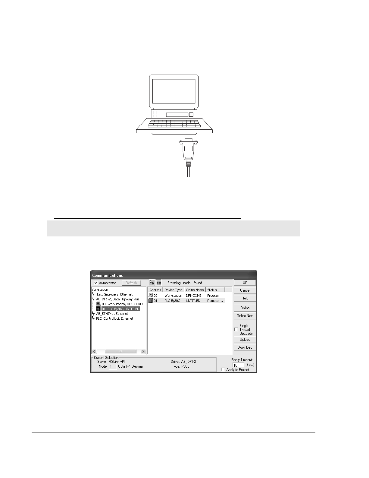
1.5 Connect your PC to the Processor
1 Connect the right-angle connector end of the cable to your controller at the
communications port.
ProSoft Technology, Inc. Page 13 of 100
September 22, 2008
Page 14
MVI71-DNPSNET ♦ PLC Platform Start Here
Distributed Network Protocol Interface Module
2 Connect the straight connector end of the cable to the serial port on your
computer.
1.6 Download the Sample Program to the Processor
To download the sample program from RSLogix 5 to the PLC processor:
Note: The key switch on the front of the PLC processor must be in the REM position.
1 If you are not already online to the processor, open the Communications
menu, and then choose Download. RSLogix will establish communication
with the processor.
2 Click the Download button to transfer the sample program to the processor.
Page 14 of 100 ProSoft Technology, Inc.
September 22, 2008
Page 15

Start Here MVI71-DNPSNET ♦ PLC Platform
Distributed Network Protocol Interface Module
3 When prompted, choose Computer to PLC
4 RSLogix will compile the program and transfer it to the processor. This
process may take a few minutes.
5 When the download is complete, RSLogix will open another confirmation
dialog box. Click OK to switch the processor from Program mode to Run
mode.
Note: If you receive an error message during these steps, refer to your RSLogix documentation to
interpret and correct the error.
1.6.1 Configuring RSLinx
If RSLogix is unable to establish communication with the processor, follow these steps:
1 Open RSLinx.
2 Open the Communications menu, and choose Configure Drivers.
ProSoft Technology, Inc. Page 15 of 100
September 22, 2008
Page 16

MVI71-DNPSNET ♦ PLC Platform Start Here
Distributed Network Protocol Interface Module
This action opens the Configure Drivers dialog box.
Note: If the list of configured drivers is blank, you must first choose and configure a driver from the
Available Driver Types list. The recommended driv er type to choose for serial communication with
the processor is "RS-232 DF1 Devices".
3 Click to select the driver, and then click Configure. This action opens the
Configure Allen-Bradley DF1 Communications Device dialog box.
4 Click the Auto-Configure button. RSLinx will attempt to configure your serial
port to work with the selected driver.
5 When you see the message "Auto Configuration Successful", click the OK
button to dismiss the dialog box.
Page 16 of 100 ProSoft Technology, Inc.
September 22, 2008
Page 17

Start Here MVI71-DNPSNET ♦ PLC Platform
Distributed Network Protocol Interface Module
Note: If the auto-configuration procedure fails, verify that the cables are connected correct ly
between the processor and the serial port on your computer, and then try again. If you are still
unable to auto-configure the port, refer to yo ur RSLinx documentation for further troubleshooting
steps.
1.7 Connect your PC to the Module
With the module securely mounted, connect your PC to the Configuration/Debug
port using an RJ45-DB-9 Serial Adapter Cable and a Null Modem Cable.
1 Attach both cables as shown.
2 Insert the RJ45 cable connector into the Configuration/Debug port of the
module.
3 Attach the other end to the serial port on your PC or laptop.
ProSoft Technology, Inc. Page 17 of 100
September 22, 2008
Page 18

MVI71-DNPSNET ♦ PLC Platform Start Here
Distributed Network Protocol Interface Module
Page 18 of 100 ProSoft Technology, Inc.
September 22, 2008
Page 19

Module Configuration MVI71-DNPSNET ♦ PLC Platform Distributed Network Protocol Interface Module
2 Module Configuration
In This Chapter
Installing and Configuring the Module ...................................................19
IP Address.............................................................................................22
Uploading and Downloading the Configuration File............................... 23
In order for the MVI71-DNPSNET module to function, a minimum amount of
configuration data must be transferred to the module. A text file named
DNPSNET.CFG is shipped with the module. This file can serve as a starting
point to develop a user application. Edit the file to configure the module for the
application.
A terminal server program is used to upload and download the configuration file
to the module. An additional file, WATTCP.CFG, must be configured for the
specific network on which the module resides.
2.1 Installing and Configuring the Module
This chapter describes how to install and configure the module to work with your
application. The configuration process consists of the following steps.
1 Modify the module's configuration files to meet the needs of your application,
and copy the updated configuration to the module. Example configuration
files are provided on the CD-ROM. Refer to the Modifying the Example
Configuration File section, later in this chapter, for more information on the
configuration files.
2 Modify the example ladder logic to meet the needs of your application, and
copy the ladder logic to the processor. Example ladder logic files are provided
on the CD-ROM.
Note: If you are installing this module in an existin g application, you can copy the necessary
elements from the example ladder logic into your application.
The rest of this chapter describes these steps in more detail.
Before installing and configuring the module, design the application. Determine
the number points for each data type. Review the Application Design section to
aid in application design.
It is now time to edit the DNPSNET.CFG file to set up the module for the specific
application. Refer to the Configuration File section of this document. Download
this configuration to the module along with the associated ladder logic.
ProSoft Technology, Inc. Page 19 of 100
September 22, 2008
Page 20

MVI71-DNPSNET ♦ PLC Platform Module Configuration
Distributed Network Protocol Interface Module
The next step in installing and configuring the module is to define whether the
block transfer or side-connect interface will be utilized. If the block transfer
interface is to be used you should be ready to connect the module to the DNP
Ethernet network if the ladder logic is defined correctly. If the side-connect
interface is to be used, you must obtain the side-connect kit, which is sold
separately.
If the side-connect interface is utilized, make sure the file SC_DATA.TXT on the
Compact Flash Disk contains the correct first file number. You can run the
setdnpsc.exe program to set the file number to be used with your application.
Install the module in the rack and turn on the power. Connect the terminal server
to the module's debug/configuration port and exit the program by pressing the
Esc key followed by the 'X' key. This will cause the program to exit and remain at
the operating system prompt. Run the setdnpsc.exe program with a command
line argument of the file number to use for the first file. For example, to select
N10: as the first file, enter the following:
SETDNPSC 10
The program will build the SC_DATA.TXT on the Compact Flash Disk (C: drive in
the root directory).
Next, define the data files to be used with the application. If the block transfer
interface is used, define the data files to hold the user data (read and write data).
Enter the ladder logic to handle the blocks transferred between the module and
the PLC. Download the program to the PLC and test the program with the
module.
If the side-connect interface is used, no ladder logic is required for data transfer.
The user data files to interface with the module must reside in contiguous order
in the processor. The first file to be used by the interface is the status/control file.
This is file number set in the SC_DATA.TXT file using the SETDNPSC.EXE
program. The following table lists the files used by the side-connect interface:
File Number Example Size Description
Cfg File N10 100 Control/Status File
Cfg File+1 N11 to 1000 Data transferred from the module to the processor
Other files for read data
Cfg File+1+n N12 to 1000 Data transferred from the processor to the module
Cfg File+1+n+m Other files for write data
n is the number of read data files minus one. Each file contains up to 1000
words.
m is the number of write data files minus one. Each file contains up to 1000
words.
More than one read and/or write file may exist in an application. This is required
when more than 1000 words of data are required. Two examples are given for
the files used with different data set sizes:
Page 20 of 100 ProSoft Technology, Inc.
September 22, 2008
Page 21

Module Configuration MVI71-DNPSNET ♦ PLC Platform
Distributed Network Protocol Interface Module
2.1.1 Example of 240 words of read and write data (cfg file=10)
Data Files Description
N11:0 to 239 Read data
N12:0 to 239 Write data
Example of 2300 read and 3500 write data registers (cfg file=10)
Data Files Description
N11:0 to 999 Read data words 0 to 999
N12:0 to 999 Read data words 1000 to 1999
N13:0 to 299 Read data words 2000 to 2299
N14:0 to 999 Write data words 0 to 999
N15:0 to 999 Write data words 1000 to 1999
N16:0 to 999 Write data words 2000 to 2999
N17:0 to 499 Write data words 3000 to 3499
Even if the files are not required for an application, they still are reserved and
should only be used for that purpose. The read and write data contained in the
last set of files possess the data transferred between the module and the
processor. The read data file (Cfg File + 1) will contain data transferred from the
module to the processor and should be associated with control data types. The
write data file (Cfg File + 1 + n) will contain data passed to the module from the
processor and should be associated with monitor data types.
Special care must be taken when defining the files for the side-connect interface.
Because the module directly interacts with the PLC processor and its memory,
any errors in the configuration may cause the processor to fault and it may even
lose its configuration and program. After defining the files and populating them
with the correct data, download the program to the processor, and place the
processor in run mode. If everything is configured correctly, the module should
start its normal operation.
The module is now and ready to be used with your application. Insert the module
in the rack (with the power turned off) and attach the serial communication cable.
Download the new application to the controller and place the processor in run
mode. Download the new DNPSNET.CFGfile to the module using a terminal
emulation program. If all the configuration parameters are set correctly and the
module is attached to a network, the module's Application LED (APP LED)
should remain off and the backplane activity LED (BP ACT) should blink very
rapidly. Refer to the Diagnostics and Trouble Shooting section if you
encounter errors. Attach a computer or terminal to Port 0 on the module and look
at the status of the module using the Configuration/Debug Menu in the module.
ProSoft Technology, Inc. Page 21 of 100
September 22, 2008
Page 22

MVI71-DNPSNET ♦ PLC Platform Module Configuration
Distributed Network Protocol Interface Module
2.2 IP Address
In addition to the DNPSNET.CFG, the MVI71-DNPSNET module requires a
second configuration file that identifies its Ethernet configuration. Without this
configuration file, the module will not communicate properly on the network.
This file contains the Ethernet address information to be used by the module and
may be transferred to and from the module from the Network command
available on the debug port of the module. Please consult your network
administrator for the correct settings for your network before placing this or any
other Ethernet TCP/IP device upon your network.
Important: If the field "my_ip" does not exist, or if the wattcp.cfg file is corrupted or does not exist,
the module will not function.
To set the Module's IP Address
1 Locate the sample configuration files for your module on the ProSoft
Solutions CD.
2 Copy the configuration files and ladder to a location on your PC's hard drive.
We recommend C:\temp.
3 After you move the files, right-click on each of the files, choose Properties,
and clear the READ ONLY check box.
4 Start Notepad.exe, or any other editor that can save plain text files.
5 Open the file WATTCP.CFG. The following example shows the contents of a
typical WATTCP.CFG file.
# ProSoft Technology
# Default private class 3 address
my_ip=192.168.0.100
# Default class 3 network mask
netmask=255.255.255.0
# The gateway I wish to use
gateway=192.168.0.1,192.168.0.0,255.255.255.0
6 Edit the file, using the IP addresses supplied by your network administrator.
Important: The module does not support DHCP (Dynamic Host Configuration Protocol) for
obtaining an IP address from a server. This module must have its own static IP address that does
not duplicate the IP address of any other device on the Ethernet netw ork.
7 Save the file as WATTCP.CFG. You must now transfer the file to the module.
Refer to Transferring WATTCP.CFG to the module (page 26, page 42) for the
correct procedure.
Page 22 of 100 ProSoft Technology, Inc.
September 22, 2008
Page 23

Module Configuration MVI71-DNPSNET ♦ PLC Platform
Distributed Network Protocol Interface Module
2.3 Uploading and Downloading the Configuration File
ProSoft modules are shipped with a pre-loaded configuration file. In order to edit
this file, you must transfer the file from the module to your PC. After editing, you
must transfer the file back to the module.
This section describes these procedures.
Important: The illustrations of configuration/debug menus in this section are intended as a general
guide, and may not exactly match the configuration/debug menus in your own module. For specific
information about the configuration/debug menus in your module, refer to The Configuration/Debug
Menu (page 33).
2.3.1 Required Hardware
You can connect directly from your computer's serial port to the serial port on the
module to view configuration information, perform maintenance, and send
(upload) or receive (download) configuration files.
ProSoft Technology recommends the following minimum hardware to connect
your computer to the module:
80486 based processor (Pentium preferred)
1 megabyte of memory
At least one UART hardware-based serial communications port available.
USB-based virtual UART systems (USB to serial port adapters) often do not
function reliably, especially during binary file transfers, such as when
uploading/downloading configuration files or module firmware upgrades.
A null modem serial cable.
2.3.2 Required Software
In order to send and receive data over the serial port (COM port) on your
computer to the module, you must use a communication program (terminal
emulator).
A simple communication program called HyperTerminal is pre-installed with
recent versions of Microsoft Windows operating systems. If you are connecting
from a machine running DOS, you must obtain and install a compatible
communication program. The following table lists communication programs that
have been tested by ProSoft Technology.
DOS ProComm, as well as several other terminal emulation programs
Windows 3.1 Terminal
Windows 95/98 HyperTerminal
Windows NT/2000/XP HyperTerminal
The module uses the Zmodem file transfer protocol to send (upload) and receive
(download) configuration files from your module. If you use a communication
program that is not on the list above, please be sure that it supports Zmodem file
transfers.
ProSoft Technology, Inc. Page 23 of 100
September 22, 2008
Page 24

MVI71-DNPSNET ♦ PLC Platform Module Configuration
Distributed Network Protocol Interface Module
2.3.3 Transferring the Configuration File to Your PC
1 Connect your PC to the Configuration/Debug port of the module using a
terminal program such as HyperTerminal. Press [?] to display the main
menu.
2 From the Transfer menu in HyperTerminal, select Receive File.
3 In the Receive File dialog box, browse to the location on your PC where the
configuration file should be stored, and select Zmodem (or Zmodem with
Crash Recovery) as the receiving protocol.
When you have completed your selections, click Close.
Page 24 of 100 ProSoft Technology, Inc.
September 22, 2008
Page 25

Module Configuration MVI71-DNPSNET ♦ PLC Platform
Distributed Network Protocol Interface Module
4 Press [S] (Send Module Configuration), and then press [Y] to confirm the
transfer.
The file transfer will then begin automatically, using the protocol and location
you specified in Step 3.
When the configuration file has been transferred to your PC, the dialog box
will indicate that the transfer is complete.
The configuration file is now on your PC at the location you specified.
5 You can now open and edit the file in a text editor such as Notepad. When
you have finished editing the file, save it and close Notepad.
ProSoft Technology, Inc. Page 25 of 100
September 22, 2008
Page 26

MVI71-DNPSNET ♦ PLC Platform Module Configuration
Distributed Network Protocol Interface Module
2.3.4 Transferring the Configuration File to the Module
Perform the following steps to transfer a configuration file from your PC to the
module.
1 Connect your PC to the Configuration/Debug port of the module using a
terminal program such as HyperTerminal. Press [?] to display the main
menu.
2 Press [R] (Receive Module Configuration). The message "Press Y key to
confirm configuration receive!" is displayed at the bottom of the screen.
3 Press [Y]. The screen now indicates that the PC is ready to send.
Page 26 of 100 ProSoft Technology, Inc.
September 22, 2008
Page 27

Module Configuration MVI71-DNPSNET ♦ PLC Platform
Distributed Network Protocol Interface Module
4 From the Transfer menu in HyperTerminal, select Send File.
The Send File dialog appears.
5 Use the Browse button to locate the configuration file your computer.
Note: This procedure assumes that you are uploading a newly edited configuration file from your
PC to the module. However, configuration files ar e also available on the ProSoft CD as well as the
ProSoft Technology web site.
6 Select Zmodem as the protocol.
ProSoft Technology, Inc. Page 27 of 100
September 22, 2008
Page 28

MVI71-DNPSNET ♦ PLC Platform Module Configuration
Distributed Network Protocol Interface Module
7 Click the Send button. This action opens the Zmodem File Send dialog box.
When the upload is complete, the screen indicates that the module has
reloaded program values and displays information about the module.
8 Your module now contains the new configuration.
Page 28 of 100 ProSoft Technology, Inc.
September 22, 2008
Page 29

Ladder Logic MVI71-DNPSNET ♦ PLC Platform Distributed Network Protocol Interface Module
3 Ladder Logic
In This Chapter
Module Data .......................................................................................... 29
Ladder logic is required for application of the MVI71-DNPSNET module. Tasks
that must be handled by the ladder logic are module data transfer, special block
handling and status data receipt. Additionally, a power-up handler may be
needed to handle the initialization of the module's data and to clear any
processor fault conditions.
The sample ladder logic, on the ProSoft Solutions CD-ROM, is extensively
commented, to provide information on the purpose and function of each rung. For
most applications, the sample ladder will work without modification.
3.1 Module Data
All data related to the MVI71-DNPSNET module is stored in a user defined data
file. It is the responsibility of the ladder logic programmer to construct all the data
files required by the program and to write the ladder logic required to interface to
these files.
3.1.1 Status Data
When the side-connect interface is employed in the application, the status data is
automatically transferred from the module to the first file used by the interface.
The data is placed at an offset of 0 in the file and has the following format:
Word Variable Name Description
0 Scan Counter
1 to 2 Product Name (ASCII)
3 to 4 Revision (ASCII)
5 to 6
7 to 8
9 Read Block Count
10 Write Block Count
11 Parse Block Count
Operating System
Revision (ASCII)
Production Run Number
(ASCII)
Program scan counter incremented each time the program
loop is executed.
These two words contain the product name of the module in
ASCII format.
These two words contain the product revision level of the
firmware in ASCII format.
These two words contain the module's internal operating
system revision level in ASCII format.
These two words contain the production 'batch' number for
the particular chip in the module in ASCII format.
Total number of blocks transferred from the module to the
processor.
Total number of blocks transferred from the processor to the
module.
Total number of blocks parsed by the module that were
received from the processor.
ProSoft Technology, Inc. Page 29 of 100
September 22, 2008
Page 30

MVI71-DNPSNET ♦ PLC Platform Ladder Logic
Distributed Network Protocol Interface Module
Word Variable Name Description
12 Block number error
13
14
15
16
17
18
19
20
21
22
23
24
25
26
27
28
DNP Slave Port total
number of message
frames received by
slave
DNP Slave Port total
number of response
message frames sent
from slave
DNP Slave Port total
number of message
frames seen by slave
DNP Slave
synchronization error
count (Physical Layer
Error)
DNP Slave overrun error
count (Physical Layer
Error)
DNP Slave length error
count (Physical Layer
Error)
DNP Slave bad CRC
error (Data Link Layer
Error)
DNP Slave user data
overflow error (Transport
Layer Error)
DNP Slave sequence
error (Transport Layer
Error)
DNP Slave address
error
(Transport Layer Error)
DNP Slave Binary Input
Event count
DNP Slave Binary Input
Event count in buffer
DNP Slave Analog Input
Event count
DNP Slave Analog Input
Event count in buffer
DNP Slave bad function
code error (Application
Layer Error)
DNP Slave object
unknown error
(Application Layer Error)
Number of BTW requests that resulted in an incorrect BTW
identification code.
This value represents the total number of message frames
that have matched this slaves address on this port. This
count includes message frames which the slave may or may
not be able to parse and respond.
This value represents the number of good (non-error)
responses that the slave has sent to the master on this port.
The presumption is that if the slave is responding, the
message was good. Note: This is a frame count.
This value represents the total number of message frames
received by the slave, regardless of the slave address.
This value counts the number of times a sync error occurs.
The error occurs when extra bytes are received before the
start bytes (0x05 and 0x64) are received.
This value counts the number of times the overrun error
occurs. This error occurs when the mainline Data Link Layer
routine cannot read the data received on the communication
port before it is overwritten.
This value counts the number of times an invalid length byte
is received. If the length of the message does not match the
length value in the message, this error occurs.
This value counts the number of times a bad CRC value is
received in a message.
This value counts the number of times the application layer
receives a message fragment buffer which is too small.
This value counts the number of times the sequence
numbers of multi-frame request fragments do not increment
correctly.
This value counts the number of times the source addresses
contained in a multi-frame request fragments do not match.
This value contains the total number of binary input events
which have occurred.
This value represents the number of binary input events
which are waiting to be sent to the master.
This value contains the total number of analog input events
which have occurred.
This value represents the number of analog input events
which are waiting to be sent to the master.
This value counts the number of times a bad function code
for a selected object/variation is received by the slave
device.
This value counts the number of times a request for an
unsupported object is received by the slave device.
Page 30 of 100 ProSoft Technology, Inc.
September 22, 2008
Page 31

Ladder Logic MVI71-DNPSNET ♦ PLC Platform
Distributed Network Protocol Interface Module
Word Variable Name Description
29
30
31
32 Free MemoryLSB
33 Free MemoryMSB
DNP Slave out of range
error (Application Layer
Error)
DNP Slave message
overflow error
(Application Layer Error)
DNP Slave multi-frame
message from DNP
Master error (Application
Layer Error)
This value counts the number of times a parameter in the
qualifier, range or data field is not valid or out of range.
This value counts the number of times an application
response message from the slave is too long to transmit.
This value counts the number of times the slave receives a
multi-frame message from the master. The application does
not support multi-frame master messages.
Free memory in module
When the block transfer interface is used, the status data is placed in the
module's internal database at the location specified by the Error Offset parameter
in the configuration file. If this data area is transferred to the processor in the
read data area, it will be passed from the module to the processor in a normal
BTR block. This will be placed in the normal read data area. The format of the
data is exactly the same as shown above, but the user determines its position.
Refer to the Reference Chapter for a complete listing of the data stored in this
object.
3.1.2 User Data
When the side-connect interface is utilized, the read and write data is moved
between the module and the processor without any ladder logic. The size of the
data area and position of the data areas in the module's database is determined
by the parameters set in the configuration file.
When the block transfer interface is used, ladder logic is required to page the
data between the module and the processor. The size of the data area and
position of the data areas in the module's database is determined by the
parameters set in the configuration file.
The read data area should be set to match the value entered in the Read
Register Count parameter of the DNPSNET.CFG file. For ease of use, this array
should be dimensioned as an even increment of 60 words. This data is paged up
to 60 words at a time from the module to the processor. The Read Data task is
responsible for placing the data received into the proper position in the read data
array. Use this data for status and control in the ladder logic of the processor.
The write data area should be set to match the value entered in the Write
Register Count parameter of the DNPSNET.CFG file. For ease of use, this array
should be dimensioned as even increments of 60 words. This data is paged up to
60 words at a time from the processor to the module. The Write Data task is
responsible for placing the write data into the output image for transfer to the
module. This data is passed from the processor to the module for status and
control information for use in other nodes on the network.
ProSoft Technology, Inc. Page 31 of 100
September 22, 2008
Page 32

MVI71-DNPSNET ♦ PLC Platform Ladder Logic
Distributed Network Protocol Interface Module
Page 32 of 100 ProSoft Technology, Inc.
September 22, 2008
Page 33

Diagnostics and Troubleshooting MVI71-DNPSNET ♦ PLC Platform Distributed Network Protocol Interface Module
4 Diagnostics and Troubleshooting
In This Chapter
Reading Status Data from the Module ..................................................33
LED Status Indicators............................................................................ 43
The module provides information on diagnostics and troubleshooting in the
following forms:
Status data values are transferred from the module to the processor.
Data contained in the module can be viewed through the
Configuration/Debug port attached to a terminal emulator.
LED status indicators on the front of the module provide information on the
module's status.
4.1 Reading Status Data from the Module
The MVI71-DNPSNET module returns a 34-word Status Data block that can be
used to determine the module's operating status. This data can be located in the
module's database at registers at the location specified in the configuration. This
data is transferred to the PLC processor continuously when the side-connect
interface is used.
The Configuration/Debug port provides the following functionality:
Full view of the module's configuration data
View of the module's status data
Complete display of the module's internal database (registers 0 to 8999)
Version Information
Control over the module (warm boot and cold boot)
Facility to upload and download the module's configuration file
4.1.1 The Configuration/Debug Menu
The Configuration and Debug menu for this module is arranged as a tree
structure, with the Main Menu at the top of the tree, and one or more sub-menus
for each menu command. The first menu you see when you connect to the
module is the Main menu.
Because this is a text-based menu system, you enter commands by typing the
command letter from your computer keyboard in the terminal application (for
example, HyperTerminal). The module does not respond to mouse movements
or clicks. The command executes as soon as you press the command letter —
you do not need to press [Enter]. When you type a command letter, a new
screen will be displayed in your terminal application.
ProSoft Technology, Inc. Page 33 of 100
September 22, 2008
Page 34

MVI71-DNPSNET ♦ PLC Platform Diagnostics and Troubleshooting
Distributed Network Protocol Interface Module
Navigation
All of the sub-menus for this module contain commands to redisplay the menu or
return to the previous menu. You can always return from a sub-menu to the next
higher menu by pressing [M] on your keyboard.
The organization of the menu structure is represented in simplified form in the
following illustration:
The remainder of this section shows you the menus available for this module,
and briefly discusses the commands available to you.
Keystrokes
The keyboard commands on these menus are almost always non-case sensitive.
You can enter most commands in lower case or capital letters.
The menus use a few special characters ([?], [-], [+], [@]) that must be entered
exactly as shown. Some of these characters will require you to use the [Shift],
[Ctrl] or [Alt] keys to enter them correctly. For example, on US English
keyboards, enter the [?] command as [Shift][/].
Also, take care to distinguish capital letter [I] from lower case letter [l] (L) and
number [1]; likewise for capital letter [O] and number [0]. Although these
characters look nearly the same on the screen, they perform different actions on
the module.
4.1.2 Required Hardware
You can connect directly from your computer's serial port to the serial port on the
module to view configuration information, perform maintenance, and send
(upload) or receive (download) configuration files.
ProSoft Technology recommends the following minimum hardware to connect
your computer to the module:
80486 based processor (Pentium preferred)
1 megabyte of memory
At least one UART hardware-based serial communications port available.
USB-based virtual UART systems (USB to serial port adapters) often do not
function reliably, especially during binary file transfers, such as when
uploading/downloading configuration files or module firmware upgrades.
A null modem serial cable.
Page 34 of 100 ProSoft Technology, Inc.
September 22, 2008
Page 35

Diagnostics and Troubleshooting MVI71-DNPSNET ♦ PLC Platform
Distributed Network Protocol Interface Module
4.1.3 Required Software
In order to send and receive data over the serial port (COM port) on your
computer to the module, you must use a communication program (terminal
emulator).
A simple communication program called HyperTerminal is pre-installed with
recent versions of Microsoft Windows operating systems. If you are connecting
from a machine running DOS, you must obtain and install a compatible
communication program. The following table lists communication programs that
have been tested by ProSoft Technology.
DOS ProComm, as well as several other terminal emulation programs
Windows 3.1 Terminal
Windows 95/98 HyperTerminal
Windows NT/2000/XP HyperTerminal
The module uses the Zmodem file transfer protocol to send (upload) and receive
(download) configuration files from your module. If you use a communication
program that is not on the list above, please be sure that it supports Zmodem file
transfers.
4.1.4 Using the Configuration/Debug Port
To connect to the module's Configuration/Debug port:
1 Connect your computer to the module's port using a null modem cable.
2 Start the communication program on your computer and configure the
communication parameters with the following settings:
Baud Rate 57,600
Parity None
Data Bits 8
Stop Bits 1
Software Handshaking None
3 Open the connection. When you are connected, press the [?] key on your
keyboard. If the system is set up properly, you will see a menu with the
module name followed by a list of letters and the commands associated with
them.
If there is no response from the module, follow these steps:
1 Verify that the null modem cable is connected properly between your
computer's serial port and the module. A regular serial cable will not work.
2 Verify that RSLinx is not controlling the COM port. Refer to Disabling the
RSLinx Driver for the Com Port on the PC (page 63).
3 Verify that your communication software is using the correct settings for baud
rate, parity and handshaking.
4 On computers with more than one serial port, verify that your communication
program is connected to the same port that is connected to the module.
If you are still not able to establish a connection, you can contact ProSoft
Technology Technical Support for further assistance.
ProSoft Technology, Inc. Page 35 of 100
September 22, 2008
Page 36

MVI71-DNPSNET ♦ PLC Platform Diagnostics and Troubleshooting
Distributed Network Protocol Interface Module
4.1.5 Main Menu
When you first connect to the module from your computer, your terminal screen
will be blank. To activate the main menu, press the [?] key on your computer's
keyboard. If the module is connected properly, the following menu will appear on
your terminal screen:
Caution: Some of the commands available to you from this menu ar e designed for advanced
debugging and system testing only, and can cause the module to stop communicating with the
processor or with other devices, resulting in potential data loss or other failures. Only use these
commands if you are specifically directed to do so by ProSoft Technology Technical Support staff.
Some of these command keys are not listed on the menu, but are active nevertheless. Please be
careful when pressing keys so that you do not accidentally execute an unwante d command.
Viewing Block Transfer Statistics
Press [B] from the Main Menu to view the Block Transfer Statistics screen.
Use this command to display the configuration and statistics of the backplane
data transfer operations between the module and the processor. The information
on this screen can help determine if there are communication problems between
the processor and the module.
Tip: To determine the number of blocks transferred each second, mark the numbers displayed at a
specific time. Then some seconds later activate the command again. Subtract the previous
numbers from the current numbers and divide by the quantity of seconds passed between the two
readings.
Viewing Module Configuration
Press [C] to view the Module Configuration screen.
Use this command to display the current configuration and statistics for the
module.
Opening the Database Menu
Press [D] to open the Database View menu. Use this menu command to view the
current contents of the module's database.
Page 36 of 100 ProSoft Technology, Inc.
September 22, 2008
Page 37

Diagnostics and Troubleshooting MVI71-DNPSNET ♦ PLC Platform
Distributed Network Protocol Interface Module
Opening the DNP Menu
Press [I] from the Main Menu to open the DNP Menu. This menu allows you to
view all data associated with the DNP Server driver. For more information about
the commands on this menu, refer to DNP Menu (page 38).
Receiving the Configuration File
Press [R] to download (receive) the current configuration file from the module.
For more information on receiving and sending configuration files, please see
Uploading and Downloading the Configuration File (page 23).
Sending the Configuration File
Press [S] to upload (send) an updated configuration file to the module. For more
information on receiving and sending configuration files, please see Uploading
and Downloading the Configuration File (page 23).
Viewing Version Information
Press [V] to view Version information for the module.
Use this command to view the current version of the software for the module, as
well as other important values. You may be asked to provide this information
when calling for technical support on the product.
Values at the bottom of the display are important in determining module
operation. The Program Scan Counter value is incremented each time a
module's program cycle is complete.
Tip: Repeat this command at one-second intervals to determine the frequency of program
execution.
Warm Booting the Module
Caution: Some of the commands available to you from this menu ar e designed for advanced
debugging and system testing only, and can cause the module to stop communicating with the
processor or with other devices, resulting in potential data loss or other failures. Only use these
commands if you are specifically directed to do so by ProSoft Technology Technical Support staff.
Some of these command keys are not listed on the menu, but are active nevertheless. Please be
careful when pressing keys so that you do not accidentally execute an unwante d command.
Press [W] from the Main Menu to warm boot (restart) the module. This command
will cause the program to exit and reload, refreshing configuration parameters
that must be set on program initialization. Only use this command if you must
force the module to re-boot.
Opening the Network Menu
Press [@] to open the network menu. The network menu allows you to send,
receive and view the WATTCP.CFG file that contains the IP, gateway and other
network specification information. You can find more information about the
commands on this menu in the Network Menu (page 42) section.
ProSoft Technology, Inc. Page 37 of 100
September 22, 2008
Page 38

MVI71-DNPSNET ♦ PLC Platform Diagnostics and Troubleshooting
Distributed Network Protocol Interface Module
Exiting the Program
Caution: Some of the commands available to you from this menu ar e designed for advanced
debugging and system testing only, and can cause the module to stop communicating with the
processor or with other devices, resulting in potential data loss or other failures. Only use these
commands if you are specifically directed to do so by ProSoft Technology Technical Support staff.
Some of these command keys are not listed on the menu, but are active nevertheless. Please be
careful when pressing keys so that you do not accidentally execute an unwante d command.
Press [Esc] to restart the module and force all drivers to be loaded. The module
will use the configuration stored in the module's Flash ROM to configure the
module.
4.1.6 DNP Menu
This opens the DNP menu. After the option is selected, press the '?' key to
display the menu and the following is displayed:
Each option on the menu is discussed in the following topics.
Viewing DNP Set Up & Pointers
Press [B] to display the memory allocation and the database setup parameters.
Viewing DNP Configuration
Press [C] to displays the configuration information for the server. Use this
command to confirm that the module is configured as desired. If any parameter is
not set correctly, adjust the configuration file and download the altered file to the
unit.
Opening the DNP Database View Menu
Press [D] to open the DNP Database View menu. Use this command to display
the database associated with each data type.
Viewing a List of Valid Hosts
Press [I] to view the list of IP addresses from which the module will accept
connections This list is only used if the module configuration parameter, Use IP
List, is set to a value other than 0.
Page 38 of 100 ProSoft Technology, Inc.
September 22, 2008
Page 39

Diagnostics and Troubleshooting MVI71-DNPSNET ♦ PLC Platform
Distributed Network Protocol Interface Module
Returning to the Main Menu
Press [M] to return to the Main Menu.
Viewing DNP Communication Status
Press [1] to view DNP Communication Status. Use this command to view the
communication status data for the DNP driver.
Viewing TCP Socket Status
Press [2] to view the status of the TCP socket in the module. After selecting the
option, the following is displayed:
The parameters displayed have the following definitions:
Rx Count - Number of messages received on TCP socket
Tx Count - Number of messages transmitted on TCP socket
Tx State - 0=not transmitting, 1=transmitting
TCP State - Value used for TCP/IP socket state machine
Busy Flag - 0=not busy, 1=TCP has control of DNP server, 2=UDP has control
of DNP server, 3=Unsolicited message being sent
App Frame - 0=no application data frame data, 1=application data available
Tx Frame - 0=Data link level frame ready to send, 1=Data link level message not
ready to send
Packet Length - Length of message left to process
Viewing UDP Socket Status
Press [3] to view the status of the UDP socket in the module. After selecting the
option, the following is displayed:
ProSoft Technology, Inc. Page 39 of 100
September 22, 2008
Page 40

MVI71-DNPSNET ♦ PLC Platform Diagnostics and Troubleshooting
Distributed Network Protocol Interface Module
The parameters displayed have the following definitions:
Rx Count - Number of messages received on UDP socket
Tx Count - Number of messages transmitted on UDP socket
Tx State - 0=not transmitting, 1=transmitting
TCP State - Value used for UDP/IP socket state machine
Busy Flag - 0=not busy, 1=TCP has control of DNP server, 2=UDP has control
of DNP server, 3=Unsolicited message being sent
App Frame - 0=no application data frame data, 1=application data available
Tx Frame - 0=Data link level frame ready to send, 1=Data link level message not
ready to send
Packet Length - Length of message left to process
4.1.7 Database View Menu
Press [D] from the Main Menu to open the Database View menu. Use this menu
command to view the current contents of the module's database. Press [?] to
view a list of commands available on this menu.
Viewing Register Pages
To view sets of register pages, use the keys described below:
Command Description
[0]
[1]
[2]
Display registers 0 to 99
Display registers 1000 to 1099
Display registers 2000 to 2099
And so on. The total number of register pages available to view depends on your
module's configuration.
Page 40 of 100 ProSoft Technology, Inc.
September 22, 2008
Page 41

Diagnostics and Troubleshooting MVI71-DNPSNET ♦ PLC Platform
Distributed Network Protocol Interface Module
Displaying the Current Page of Registers Again
This screen displays the current page of 100 registers in the database.
Moving Back Through 5 Pages of Registers
Press [-] from the Database View menu to skip back to the previous 500
registers of data.
Viewing the Previous 100 Registers of Data
Press [P] from the Database View menu to display the previous 100 registers of
data.
Skipping 500 Registers of Data
Hold down [Shift] and press [=] to skip forward to the next 500 registers of data.
Viewing the Next 100 Registers of Data
Press [N] from the Database View menu to select and display the next 100
registers of data.
Viewing Data in Decimal Format
Press [D] to display the data on the current page in decimal format.
Viewing Data in Hexadecimal Format
Press [H] to display the data on the current page in hexadecimal format.
Viewing Data in Floating Point Format
Press [F] from the Database View menu. Use this command to display the data
on the current page in floating point format. The program assumes that the
values are aligned on even register boundaries. If floating-point values are not
aligned as such, they are not displayed properly.
Viewing Data in ASCII (Text) Format
Press [A] to display the data on the current page in ASCII format. This is useful
for regions of the database that contain ASCII data.
Returning to the Main Menu
Press [M] to return to the Main Menu.
ProSoft Technology, Inc. Page 41 of 100
September 22, 2008
Page 42

MVI71-DNPSNET ♦ PLC Platform Diagnostics and Troubleshooting
Distributed Network Protocol Interface Module
4.1.8 Network Menu
The network menu allows you to send, receive and view the WATTCP.CFG file
that contains the IP and gateway addresses, and other network specification
information.
Transferring WATTCP.CFG to the module
Press [R] to transfer a new WATTCP.CFG file from the PC to the module. Use
this command to change the network configuration for the module (for example,
the module's IP address).
Press [Y] to confirm the file transfer, and then follow the instructions on the
terminal screen to complete the file transfer process.
Transferring WATTCP.CFG to the PC
Press [S] to transfer the WATTCP.CFG file from the module to your PC.
Press [Y] to confirm the file transfer, and then follow the instructions on the
terminal screen to complete the file transfer process.
After the file has been successfully transferred, you can open and edit the file to
change the module's network configuration.
Viewing the WATTCP.CFG file on the module
Press [V] to view the module's WATTCP.CFG file. Use this command to confirm
the module's current network settings.
Returning to the Main Menu
Press [M] to return to the Main Menu.
Page 42 of 100 ProSoft Technology, Inc.
September 22, 2008
Page 43

Diagnostics and Troubleshooting MVI71-DNPSNET ♦ PLC Platform
Distributed Network Protocol Interface Module
4.2 LED Status Indicators
The LEDs indicate the module's operating status as follows:
ProSoft
Module
CFG Green
BP Amber
OK Red/
If the APP, BP ACT and OK LEDs blink at a rate of every one-second, this
indicates a serious problem with the module. Call ProSoft Technology support to
arrange for repairs.
Color Status Indication
On
Off No data is being transferred on the Configuration/Debug port.
On Port not used P1 Green
Off Port not used
On Port not used P2 Green
Off Port not used
Off The MVI71-DNPSNET is working normally. APP Status Amber
On
On
Off
Off
Green
Green The module is operating normally.
Red
Off The battery voltage is OK and functioning. BAT Red
On
Data is being transferred between the module and a remote
terminal using the Configuration/Debug port.
The MVI71-DNPSNET module program has recognized a
communication error on one of its DNP ports.
The LED is on when the module is performing a write
operation on the backplane.
The LED is off when the module is performing a read
operation on the backplane. Under normal operation, the LED
should blink rapidly on and off.
The card is not receiving any power and is not securely
plugged into the rack.
The program has detected an error or is being configured. If
the LED remains red for over 10 seconds, the program has
probably halted. Remove the card from the rack and re-insert
the card to restart the module's program.
The battery voltage is low or battery is not present. Allow
battery to charge by keeping module plugged into rack for 24
hours. If BAT LED still does not go off, contact ProSoft
Technology, as this is not a user serviceable item.
In addition to these LEDs, the module contains two LEDs under the module's
door. The LED on the left (green) displays the link status. If the module is
connected properly to a hub, this LED should be illuminated. The LED on the
right (amber) is the data indication LED. Whenever the module is sending or
receiving data on the Ethernet interface, this LED is illuminated.
4.2.1 Ethernet LED Indicators
LED State Description
Off No activity on the port. Data
Green Flash The port is either actively transmitting or receiving data.
Off No connection to hub or network is detected. Link
Green Solid
ProSoft Technology, Inc. Page 43 of 100
September 22, 2008
Connected to hub or network correctly. This is the normal
operating state.
Page 44

MVI71-DNPSNET ♦ PLC Platform Diagnostics and Troubleshooting
Distributed Network Protocol Interface Module
4.2.2 Clearing a Fault Condition
Typically, if the OK LED on the front of the module turns red for more than ten
seconds, a hardware problem has been detected in the module, or the program
has exited.
To clear the condition, follow these steps:
1 Turn off power to the rack
2 Remove the card from the rack
3 Verify that all jumpers are set correctly
4 If the module requires a Compact Flash card, verify that the card is installed
correctly
5 Re-insert the card in the rack and turn the power back on
6 Verify the configuration data being transferred to the module from the PLC
processor.
If the module's OK LED does not turn green, verify that the module is inserted
completely into the rack. If this does not cure the problem, contact ProSoft
Technology Support.
4.2.3 Troubleshooting
Use the following troubleshooting steps if you encounter problems when the
module is powered up. If these steps do not resolve your problem, please contact
ProSoft Technology Technical Support.
Processor Errors
Problem Description Steps to take
Processor Fault
Processor I/O LED
flashes
Module Errors
Problem Description Steps to take
BP ACT LED remains
off or blinks slowly
OK LED remains red
Verify that the module is plugged into the slot that has been configured
for the module.
Verify that the slot in the rack configuration has been set up correctly in
the ladder logic.
This indicates a problem with backplane communications. Verify that all
modules in the rack are configured in the ladder logic.
This indicates that backplane transfer operations are failing. Connect to
the module's Configuration/Debug port to check this.
To establish backplane communications, verify the following items:
The processor is in Run mode.
The backplane driver is loaded in the module.
The module is configured for read and write block data transfer.
The ladder logic handles all read and write block situations.
The module is configured in the processor.
The program has halted or a critical error has occurred. Connect to the
Configuration/Debug port to see if the module is running. If the program
has halted, turn off power to the rack, remove the card from the rack and
re-insert the card in the rack, and then restore power to the rack.
Page 44 of 100 ProSoft Technology, Inc.
September 22, 2008
Page 45

Diagnostics and Troubleshooting MVI71-DNPSNET ♦ PLC Platform
Distributed Network Protocol Interface Module
4.2.4 Error Status Table
The program maintains an error/status table that is transferred to the processor
in each read block. Ladder logic should be programmed to accept this block of
data and place it in the module's controller tag. You can use the error/status data
to determine the "health" of the module.
The data in the block is structured as shown in the following table.
Word Variable Name Description
0 Scan Counter
1 to 2 Product Name (ASCII)
3 to 4 Revision (ASCII)
5 to 6
7 to 8
9 Read Block Count
10 Write Block Count
11 Parse Block Count
12 Block number error
13
14
15
16
17
18
19
Operating System Revision
(ASCII)
Production Run Number
(ASCII)
DNP Slave Port total
number of message frames
received by slave
DNP Slave Port total
number of response
message frames sent from
slave
DNP Slave Port total
number of message frames
seen by slave
DNP Slave synchronization
error count (Physical Layer
Error)
DNP Slave overrun error
count (Physical Layer Error)
DNP Slave length error
count (Physical Layer Error)
DNP Slave bad CRC error
(Data Link Layer Error)
Program scan counter incremented each time the
program loop is executed.
These two words contain the product name of the
module in ASCII format.
These two words contain the product revision level of the
firmware in ASCII format.
These two words contain the module's internal operating
system revision level in ASCII format.
These two words contain the production 'batch' number
for the particular chip in the module in ASCII format.
Total number of blocks transferred from the module to
the processor.
Total number of blocks transferred from the processor to
the module.
Total number of blocks parsed by the module that were
received from the processor.
Number of BTW requests that resulted in an incorrect
BTW identification code.
This value represents the total number of message
frames that have matched this slaves address on this
port. This count includes message frames which the
slave may or may not be able to parse and respond.
This value represents the number of good (non-error)
responses that the slave has sent to the master on this
port. The presumption is that if the slave is responding,
the message was good. Note: This is a frame count.
This value represents the total number of message
frames received by the slave, regardless of the slave
address.
This value counts the number of times a sync error
occurs. The error occurs when extra bytes are received
before the start bytes (0x05 and 0x64) are received.
This value counts the number of times the overrun error
occurs. This error occurs when the mainline Data Link
Layer routine cannot read the data received on the
communication port before it is overwritten.
This value counts the number of times an invalid length
byte is received. If the length of the message does not
match the length value in the message, this error occurs.
This value counts the number of times a bad CRC value
is received in a message.
ProSoft Technology, Inc. Page 45 of 100
September 22, 2008
Page 46

MVI71-DNPSNET ♦ PLC Platform Diagnostics and Troubleshooting
Distributed Network Protocol Interface Module
Word Variable Name Description
20
21
22
23
24
25
26
27
28
29
30
31
32 Free Memory LSB
33 Free Memory MSB
DNP Slave user data
overflow error (Transport
Layer Error)
DNP Slave sequence error
(Transport Layer Error)
DNP Slave address error
(Layer Error) (Transport
DNP Slave Binary Input
Event count
DNP Slave Binary Input
Event count in buffer
DNP Slave Analog Input
Event count
DNP Slave Analog Input
Event count in buffer
DNP Slave bad function
code error (Application
Layer Error)
DNP Slave object unknown
error (Application Layer
Error)
DNP Slave out of range
error (Application Layer
Error)
DNP Slave message
overflow error (Application
Layer Error)
DNP Slave multi-frame
message from DNP Master
error (Application Layer
Error)
This value counts the number of times the application
layer receives a message fragment buffer which is too
small.
This value counts the number of times the sequence
numbers of multi-frame request fragments do not
increment correctly.
This value counts the number of times the source
addresses contained in a multi-frame request fragments
do not match.
This value contains the total number of binary input
events which have occurred.
This value represents the number of binary input events
which are waiting to be sent to the master.
This value contains the total number of analog input
events which have occurred.
This value represents the number of analog input events
which are waiting to be sent to the master.
This value counts the number of times a bad function
code for a selected object/variation is received by the
slave device.
This value counts the number of times a request for an
unsupported object is received by the slave device.
This value counts the number of times a parameter in the
qualifier, range or data field is not valid or out of range.
This value counts the number of times an application
response message from the slave is too long to transmit.
This value counts the number of times the slave receives
a multi-frame message from the master. The application
does not support multi-frame master messages.
Free memory in module
Page 46 of 100 ProSoft Technology, Inc.
September 22, 2008
Page 47

Reference MVI71-DNPSNET ♦ PLC Platform
Distributed Network Protocol Interface Module
5 Reference
In This Chapter
Product Specifications........................................................................... 47
Functional Overview.............................................................................. 49
Cable Connections ................................................................................62
MVI71-DNPSNET Configuration Forms ................................................65
MVI71-DNPSNET Status Data .............................................................. 69
MVI71-DNPSNET Module Internal Indication Bits (IIN Bits) for DNP Server
..............................................................................................................70
Device Profile ........................................................................................72
DNP Subset Definition...........................................................................73
MVI71-DNPSNET Application Design ...................................................76
Event Size Computation........................................................................ 88
5.1 Product Specifications
The MVI71 DNP 3.0 Server over Ethernet Communications Module supports the
implementation of the DNP 3.0 (Distributed Network Protocol) over Ethernet,
allowing PLC processors to easily communicate with host systems supporting the
protocol. The module supports DNP Subset Level 2 features and some Level 3
features.
5.1.1 Features and Benefits
The MVI71-DNPSNET (Distributed Network Protocol Module over Ethernet)
allows PLC processors to easily communicate with other DNP protocolcompatible devices.
The module supports DNP subset level 2 features and some Level 3 features.
The MVI71-DNPSNET module acts as an input/output module between the DNP
Ethernet network and the Rockwell Automation backplane. The data transfer
from the PLC processor is asynchronous from the actions on the DNP network.
Databases are defined in the module to house the data required by the protocol.
5.1.2 General Specifications
Single Slot - 1771 backplane compatible
The module is recognized as an Input/Output module and has access to
processor memory for data transfer between processor and module
Ladder Logic is used for data transfer between module and processor.
Sample ladder file included.
Configuration data obtained from configuration text file downloaded to
module. Sample configuration file included.
ProSoft Technology, Inc. Page 47 of 100
September 22, 2008
Page 48

MVI71-DNPSNET ♦ PLC Platform Reference
Distributed Network Protocol Interface Module
5.1.3 Hardware Specifications
Specification Description
Form Factor
Backplane current load 800 mA @ 5 V
Operating temperature 0 to 60°C (32 to 140°F)
Storage temperature -40 to 85°C (-40 to 185°F)
Shock 30g operational
Vibration 5 g from 10150 Hz
Relative humidity 5% to 95% (non-condensing)
LED Indicators Module status
Configuration Serial port (CFG) DB-9M PC compatible
Ethernet Port (Ethernet modules) RJ45 Connector
Single Slot 1771 chassis compatible
BTR/BTW data transfer
Local or remote rack
50g non-operational
Backplane transfer status
Application status
Serial activity and error LED status
RS-232
Hardware handshaking
Link and activity LED indicators
Electrical Isolation 1500 V rms at 50 Hz to 60 Hz for 60 s,
applied as specified in section 5.3.2 of IEC 60950: 1991
Ethernet Broadcast Storm Resiliency = less than or equal to
5000 [ARP] frames-per-second and less than or equal to 5
minutes duration
5.1.4 Functional Specifications
The MVI71-DNPSNET module accepts DNP commands to control and monitor
the data stored in the DNP databases. This data is passed between the module
and the PLC processor over the backplane for use in user applications.
DNP databases to house data for the slave port supporting the following
maximum input counts
o Binary input: 8000 points (500 words)
o Binary output: 8000 points (500 words)
o Counter: 250 (500 words)
o Analog input: 500
o Analog output: 500
User-definable module memory usage
Data movement between module using block-transfer or side-connect
interface
Ethernet port supporting both TCP and UDP over Ethernet
Supports DNP 3.0 in a level 2 implementation
Supports sending of input event data from the ladder to the module
Supports time synchronization from/to processor
Network configurable via text file
Status and error information
Page 48 of 100 ProSoft Technology, Inc.
September 22, 2008
Page 49

Reference MVI71-DNPSNET ♦ PLC Platform
Distributed Network Protocol Interface Module
5.2 Functional Overview
This section provides an overview of how the MVI71-DNPSNET module transfers
data using the DNPSNET protocol. You should understand the important
concepts in this chapter before you begin installing and configuring the module.
The DNPSNET protocol driver exists as a single service port (DNPSNET port
20000) implementation that supports a single TCP port connection and multiple
UDP ports on a TCP/IP Ethernet network. The DNPSNET port operates as a
server, supporting the DNP 3.0 protocol in a Level 2 implementation using the
DNP User Group recommended extension for use on LAN/WAN. This is
published in "Transporting DNP V3.00 over Local and Wide Area Networks",
December 15, 1998 by the DNP Users Group and is available on the Internet at
http://www.dnp.org.
5.2.1 General Concepts
The following discussion explains several concepts that are important for
understanding the operation of the MVI71-DNPSNET module.
Module Power Up
On power up the module begins performing the following logical functions:
1 Initialize hardware components
o Install packet driver for Ethernet network interface and TCP/IP stack
o Initialize PLC backplane driver
o Test and clear all RAM
o Initialize the serial communication ports
2 Read configuration file from Compact Flash Disk
3 Enable Slave Driver
After the module has received the configuration, the module will begin
communicating with other nodes on the network, depending on the configuration.
ProSoft Technology, Inc. Page 49 of 100
September 22, 2008
Page 50

MVI71-DNPSNET ♦ PLC Platform Reference
Distributed Network Protocol Interface Module
Main Logic Loop
Upon completing the power up configuration process, the module enters an
infinite loop that performs the functions shown in the following diagram.
PLC Processor Not in Run
Whenever the module detects that the processor has gone out of the Run Mode
(that is, Fault or PGM), the protocol ports can be shut down as prescribed in the
user configuration. When the processor is returned to a running state, the module
resumes communications on the network.
Backplane Data Transfer
The MVI71-DNPSNET module communicates directly over the PLC backplane.
Data is paged between the module and the PLC processor across the backplane
using BTR and BTW operations. Data is transferred from the module to the
processor using the BTR blocks, and data is transferred from the processor to
the module using BTW blocks.
Page 50 of 100 ProSoft Technology, Inc.
September 22, 2008
Page 51

Reference MVI71-DNPSNET ♦ PLC Platform
Distributed Network Protocol Interface Module
The following illustration shows the data transfer method used to move data
between the PLC processor, the MVI71-DNPSNET module, and the DNP
network.
All data transferred between the module and the processor over the backplane is
through the BTR and BTW blocks. Ladder logic must be written in the PLC
processor to interface the block data with user data files. All data used by the
module is stored in its internal databases. These databases are defined as virtual
DNP data tables with addresses from 0 to the maximum number of points for
each data type.
ProSoft Technology, Inc. Page 51 of 100
September 22, 2008
Page 52

MVI71-DNPSNET ♦ PLC Platform Reference
Distributed Network Protocol Interface Module
The following illustration shows the layout of the databases:
Data contained in this database is paged through the BTR and BTW images by
coordination of the PLC ladder logic and the MVI71-DNPSNET module's
program. Up to 64 words of data can be transferred from the module to the
processor at a time. Up to 64 words of data can be transferred from the
processor to the module.
Each block transferred from the module to the processor or from the processor to
the module contains a block identification code that describes the content of the
block. The following table defines the blocks used by this module:
Block Number Function/Description
0 or -1 Dummy Blocks: Used by module when no data is to be transferred
1 to 149 DNP Data blocks
1000 to 1148 Output initialization blocks
9958 PLC Binary Input Event data
9959 PLC Analog Input Event Data
9970 Set PLC time using module's DNP time
9971 Set module's time using PLC time
9998 Warm Boot Request from PLC (Block contains no data)
9999 Cold Boot Request from PLC (Block contains no data)
Page 52 of 100 ProSoft Technology, Inc.
September 22, 2008
Page 53

Reference MVI71-DNPSNET ♦ PLC Platform
Distributed Network Protocol Interface Module
Blocks 1 through 149 transfer data between the module and the processor.
Blocks 1000 to 1148 transfer the initial output databases (binary and analog
output data) from the processor to the module at startup. Blocks 9958 to 9999
are used for command control of the module. Each group of blocks are described
in the following topics.
Normal Data Transfer
Normal data transfer includes the paging of the user data found in the module's
internal databases between the module and the controller. These data are
transferred through read (BTR) and write (BTW) blocks. Refer to the Module
Configuration section for a description of the data objects used with the blocks
and the ladder logic required. Each data block transferred between the module
and the processor has a specific block identification code that defines the data
set contained in the block. The following illustration shows the direction of
movement of the DNP data types between the module and the processor:
The structure and function of each block is described in the following topics:
ProSoft Technology, Inc. Page 53 of 100
September 22, 2008
Page 54

MVI71-DNPSNET ♦ PLC Platform Reference
Distributed Network Protocol Interface Module
Read Block
These blocks of data transfer information from the module to the PLC processor.
The structure of the BTR image used to transfer this data is shown in the
following table.
Block Offset Content
0 Read block ID
1 Write block ID
2 to 61 Read data
62 to 63 Spare (Not used)
The Read Block ID is an index value used to determine the location of where the
data will be placed in the PLC processor user data file. Each transfer can move
up to 60 words (block offsets 2 to 61) of data.
The Write Block ID associated with the block requests data from the PLC
processor. Under normal, program operation, the module sequentially sends
read blocks and requests write blocks. For example, if two blocks of read data
and three blocks of write data are to be moved between the module and the
processor, the sequence will be as follows:
R1W1
R2W2 R1W3 R2W1 R1W2 R2W3 R1W1
This sequence will continue until interrupted by other write block numbers sent by
the controller or by a command request from a node on the DNP network or
operator control through the module's Configuration/Debug port.
Write Block
These blocks of data transfer information from the PLC processor to the module.
The structure of the BTW image used to transfer this data is shown in the
following table.
Block Offset Content
0 Write block ID
1 to 60 Write data
61 to 63 Spare (Not used)
The Write Block ID is an index value used to determine the location in the
module's database where the data will be placed. Each transfer can move up to
60 words (block offsets 1 to 60) of data.
Command Control Blocks
Command control blocks are special blocks used to control the module or
request special data from the module. The current version of the software
supports several command control blocks each of which is discussed in the
following topics.
Page 54 of 100 ProSoft Technology, Inc.
September 22, 2008
Page 55

Reference MVI71-DNPSNET ♦ PLC Platform
Distributed Network Protocol Interface Module
Block 9958 or 258 - PLC Binary Input Event
If the PLC sends a block 9958, the module will place the binary input event data
in the block into the event buffer and alter the data values for the points in the
DNP binary input database. The format for the event message is shown in the
following table.
Word Offset in
Block
0 Block ID
1 Event Count
2 Sequence Counter
3
4 Month/Day/State
5 Hour/Minute
6 Sec/Millisecond
7 Year This is the four digit year for the event.
8 to 12 Five words of data for Event #2.
13 to 17 Five words of data for Event #3.
18 to 22 Five words of data for Event #4.
23 to 27 Five words of data for Event #5.
28 to 32 Five words of data for Event #6.
33 to 37 Five words of data for Event #7.
38 to 42 Five words of data for Event #8.
43 to 47 Five words of data for Event #9.
48 to 52 Five words of data for Event #10.
53 to 57 Five words of data for Event #11.
58 to 62 Five words of data for Event #12.
63 Spare Not Used
Data Field(s) Description
This field contains the value of 9958 identifying the event
block to the module.
This field contains the number of events contained in the
block. Valid values for this field are 1 to 12.
This field holds the sequence counter for each 9958
block transfer. This synchronizes and confirms receipt of
the block by the module.
DNP Binary Input
Data point
This is the data point in the DNP binary input database
represented by the event.
Formatted: bits 0 to 4 = Day, bits 8 to 11 = Month, bit 15
= digital state for point. All other bits are ignored.
Formatted: bits 0 to 5 = Minutes, bits 8 to 12 = Hour. All
other bits are ignored.
Formatted: bits 0 to 9 = Milliseconds, bits 10 to 15 =
Seconds.
Up to 12 events can be passed from the PLC to the module in each block. To
ensure that the block reached the module and was processed, the module will
send a response read block 9958 to the PLC. The format of the block is shown in
the following table.
Word Offset in
Block
0 Block ID Identification code for block set to 9958.
1 Block ID
2 Event Count
Data Field(s) Description
Block identification code for request from PLC by the
module.
This field contains the number of events processed by
the module.
ProSoft Technology, Inc. Page 55 of 100
September 22, 2008
Page 56

MVI71-DNPSNET ♦ PLC Platform Reference
Distributed Network Protocol Interface Module
Word Offset in
Block
4 to 63 Spare Not used
Data Field(s) Description
Sequence This field contains the sequence counter of 3
Counter the last successful block 9958 received.
The sequence counter field in the returned block is set to the last successfully
processed block 9958 from the PLC. Compare this value to that sent by the PLC.
If the values match, the events can be removed from the PLC. If the values do
not match, or the PLC does not receive a 9958 block, the PLC must re-send the
block.
Block 9959 or 259 - PLC Analog Input Event
If the PLC sends a block 9959, the module will place the analog input event data
in the block into the event buffer and alter the data values for the points in the
DNP analog input database. The format for the event message is shown in the
following table.
Word Offset in
Block
0 Block ID
1 Event Count
2 Sequence Counter
3
4 Analog Input Value
5 Month/Day
6 Hour/Minute
7 Sec/Millisecond
8 Year Four digit year value for event.
9 to 14 Six words of data for Event #2.
15 to 20 Six words of data for Event #3.
21 to 26 Six words of data for Event #4.
27 to 32 Six words of data for Event #5.
33 to 38 Six words of data for Event #6.
39 to 44 Six words of data for Event #7.
45 to 50 Six words of data for Event #8.
51 to 56 Six words of data for Event #9.
57 to 62 Six words of data for Event #10.
63 Spare Not Used
Data Field(s) Description
This field contains the value of 9959 identifying the event
block to the module.
This field contains the number of events contained in the
block. Valid values for this field are 1 to 10.
This field holds the sequence counter for each 9959 block
transfer. This synchronizes and confirms receipt of the
block by the module.
DNP Analog Input
Data point
This is the data point in the DNP analog input database
represented by the event.
This is the new analog input value represented in the
event.
Formatted: bits 0 to 4 = Day, bits 8 to 11 = Month. All
other bits are ignored.
Formatted: bits 0 to 5 = Minutes, bits 8 to 12 = Hour. All
other bits are ignored.
Formatted: bits 0 to 9 = Milliseconds, bits 10 to 15 =
Seconds.
Page 56 of 100 ProSoft Technology, Inc.
September 22, 2008
Page 57

Reference MVI71-DNPSNET ♦ PLC Platform
Distributed Network Protocol Interface Module
Up to 10 events can be passed from the PLC to the module in each block. To
ensure that the block reached the module and was processed, the module will
send a response read block 9959 to the PLC. The format of the block is shown in
the following table.
Word Offset in
Block
0 Block ID Identification code for block set to 9959.
1 Block ID
2 Event Count
3 Sequence Counter
4 to 63 Spare Not used
Data Field(s) Description
Block identification code for request from PLC by the
module.
This field contains the number of events processed by the
module.
This field contains the sequence counter of the last
successful block 9959 received.
The sequence counter field in the returned block is set to the last successfully
processed block 9959 from the PLC. Compare this value to that sent by the PLC.
If the values match, the events can be removed from the PLC. If the values do
not match, or the PLC does not receive a 9959 block, the PLC must re-send the
block.
Block 9970 or 270 - Set PLC Time Using Module Time
This block transfers the module's time to the PLC processor. Ladder logic must
be used to set the processor's clock using the data received. The format of the
block sent from the PLC has the following format:
Word Offset in Block Data Field(s) Description
0 Block ID
1 to 63 Not Used Not Used
This field contains the value of 9970 identifying
the block type to the module.
The module responds to the request with a read block 9970 with the following
format:
Word Offset in Block Data Field(s) Description
0 Block Read ID
1 Block Write ID This is the next block requested by the module.
2 Year
3 Month
4 Day
5 Hour
6 Minute
This field contains the block identification code of
9970 for the block.
This field contains the four-digit year to be used
with the new time value.
This field contains the month value for the new
time. Valid entry for this field is in the range of 1
to 12.
This field contains the day value for the new time.
Valid entry for this field is in the range of 1 to 31.
This field contains the hour value for the new
time. Valid entry for this field is in the range of 0
to 23.
This field contains the minute value for the new
time. Valid entry for this field is in the range of 0
to 59.
ProSoft Technology, Inc. Page 57 of 100
September 22, 2008
Page 58

MVI71-DNPSNET ♦ PLC Platform Reference
Distributed Network Protocol Interface Module
Word Offset in Block Data Field(s) Description
7 Seconds
This field contains the second value for the new
time. Valid entry for this field is in the range of 0
to 59.
8 Milliseconds
This field contains the millisecond value for the
new time. Valid entry for this field is in the range
of 0 to 999.
9
Remote Time
Synchronization
This field informs the PLC if the date and time
passed has been synchronized with a remote
DNP master device on the module's slave port.
10 to 63 Not Used Not Used
Block 9971 or 271 - Set Module's Time Using PLC Time
This block sets the clock in the module to match the clock in the PLC processor.
If the PLC sends a block 9971, the module will set its time using the data
contained the block. The format of the block is shown in the following table.
Word Offset in Block Data Field(s) Description
0 Block ID
1 Year
2 Month
3 Day
4 Hour
5 Minute
6 Seconds
7 Milliseconds
8 to 63 Not Used Not Used
This field contains the block identification code of
9971 for the block.
This field contains the four-digit year to be used
with the new time value.
This field contains the month value for the new
time. Valid entry for this field is in the range of 1
to 12.
This field contains the day value for the new time.
Valid entry for this field is in the range of 1 to 31.
This field contains the hour value for the new
time. Valid entry for this field is in the range of 0
to 23.
This field contains the minute value for the new
time. Valid entry for this field is in the range of 0
to 59.
This field contains the second value for the new
time. Valid entry for this field is in the range of 0
to 59.
This field contains the millisecond value for the
new time. Valid entry for this field is in the range
of 0 to 999.
The module responds to a valid 9971 block with a read block of the following
format:
Word Offset in Block Data Field(s) Description
0 Block Read ID
This field contains the block identification code of
9971 for the block.
1 Block Write ID This is the next block requested by the module.
2 to 63 Not Used Not Used
Page 58 of 100 ProSoft Technology, Inc.
September 22, 2008
Page 59

Reference MVI71-DNPSNET ♦ PLC Platform
Distributed Network Protocol Interface Module
Block 9998 or 255 - Warm Boot Module
If the PLC sends a block number 9998, the module performs a warm-boot
operation.
Block 9999 or 253 - Cold Boot Module
If the PLC sends a block number 9999, the application will perform the cold-boot
operation. The module exits the program and performs a soft restart on the
module.
Side-Connect Backplane Data Transfer
The side-connect interface is the simplest method to implement the module. No
ladder logic is required for the interface because the driver handles data
movement between the module and the processor automatically. The data flow
associated with this interface is shown in the following diagram:
The configuration information for the module determines the size of the read and
write data areas and the locations of these data sets in the module's internal
database. Therefore, to use this interface, just set up the files required by the
module. The following table lists the files required for the side-connect interface:
File Number Example Size Description
Cfg File N10 100 Control/Status File
Data transferred from the module to the processor Cfg File+1 N11 to 1000
Other files for read data
Cfg File+1+n N12 to 1000 Data transferred from the processor to the module
Cfg File+1+n+m Other files for write data
ProSoft Technology, Inc. Page 59 of 100
September 22, 2008
Page 60

MVI71-DNPSNET ♦ PLC Platform Reference
Distributed Network Protocol Interface Module
n is the number of read data files minus one. Each file contains up to 1000
words.
m is the number of write data files minus one. Each file contains up to 1000
words.
The number of read and write files are dependent on the modules configuration.
Two examples follow:
Example of 240 words of read and write data (cfg file=10)
Data Files Description
N11:0 to 239 Read data
N12:0 to 239 Write data
Example of 2300 read and 3500 write data registers (cfg file=10)
Data Files Description
N11:0 to 999 Read data words 0 to 999
N12:0 to 999 Read data words 1000 to 1999
N13:0 to 299 Read data words 2000 to 2299
N14:0 to 999 Write data words 0 to 999
N15:0 to 999 Write data words 1000 to 1999
N16:0 to 999 Write data words 2000 to 2999
N17:0 to 499 Write data words 3000 to 3499
Command control is also supported on the side-connect interface. A reserved
data area in the first user data file for the interface in the PLC is utilized for this
function. Starting at register 50 in the file and extending for 64 registers is the
location of the data area. The format for the control blocks is identical to that
described in the previous sections. The only difference is in the response blocks
from the module. Register 50 will be set to zero when the function is complete
and register 51 will contain the command control code requested. The BTW
block identification code is not included and the data shown starting at word 2 is
contained in registers 52 to 113.
Page 60 of 100 ProSoft Technology, Inc.
September 22, 2008
Page 61

Reference MVI71-DNPSNET ♦ PLC Platform
Distributed Network Protocol Interface Module
Data Flow Between MVI71-DNPSNET Module and the PLC Processor
The following topics describe the flow of data between the two pieces of
hardware (PLC processor and MVI71-DNPSNET module) and other nodes on
the DNP network for the block-transfer interface. Data is automatically moved
between the module and the processor when the side-connect interface is
employed. The DNP Server Driver allows the MVI71-DNPSNET module to
respond to data read and write commands issued by a master on the DNP
network. The following flow chart and associated table describe the flow of data
into and out of the module.
Step Description
1
2
3
4
5
6
The configuration information for the module is retrieved from the DNPSNET.CFGfile on
the Compact Flash Disk. This information configures the module and define the Ethernet
node characteristics.
A Host device (DNP Master unit) issues a read or write command to the module's node
address. The driver qualifies the message before accepting it into the module.
After the module accepts the command, the data is immediately transferred to or from
the appropriate internal database in the module. If the command is a read command, the
data is read out of the database and a response message is built. If the command is a
write command, the data is written directly into the database and a response message is
built.
After the data processing has been completed in Step 3, the response is issued to the
originating master node.
Counters are available in the Status Block that permit the ladder logic program to
determine the level of activity of the Slave Driver.
The module constantly monitors for command control blocks from the processor. If a
valid block is received, the function is executed. Additionally, data is constantly being
exchanged between the module and the processor.
Review the Module Configuration section for a complete list of the parameters
that must be defined for a slave port.
ProSoft Technology, Inc. Page 61 of 100
September 22, 2008
Page 62

MVI71-DNPSNET ♦ PLC Platform Reference
Distributed Network Protocol Interface Module
5.3 Cable Connections
The MVI71-DNPSNET module has the following communication connections on
the module:
One Ethernet port (RJ45 connector)
One RS-232 Configuration/Debug port (RJ45 connector)
5.3.1 Ethernet Connection
The MVI71-DNPSNET module has an RJ45 port located on the front of the
module labeled "Ethernet", for use with the TCP/IP network. The module is
connected to the Ethernet network using an Ethernet cable between the module's
Ethernet port and an Ethernet switch or hub.
Note: Depending on hardware configuration, you may see more than one RJ45 port o n the
module. The Ethernet port is labeled "Ethernet".
Warning: The MVI71-DNPSNET module is NOT compatible with Power Over Eth ernet
(IEEE802.3af / IEEE802.3at) networks. Do NOT connect the module to Ethernet devices, hubs,
switches or networks that supply AC or DC power over the Ethernet cable. Failure to observe this
precaution may result in damage to hardware, or injury to personnel.
Important: The module requires a static (fixed) IP address that is not shared with any other device
on the Ethernet network. Obtain a list of suitable IP addresses from your network administrator
BEFORE configuring the Ethernet port on this module.
Ethernet Port Configuration - wattcp.cfg
The wattcp.cfg file must be set up properly in order to use a TCP/IP network
connection. You can view the current network configuration using an ASCII
terminal by selecting "@" (Network Menu) and "V" (View) options when
connected to the Debug port.
# WATTCP.CFG FILE:
# ProSoft Technology.
my_ip=192.168.0.100
# Default class 3 network mask
netmask=255.255.255.0
# The gateway I wish to use
gateway=192.168.0.1
Page 62 of 100 ProSoft Technology, Inc.
September 22, 2008
Page 63

Reference MVI71-DNPSNET ♦ PLC Platform
Distributed Network Protocol Interface Module
5.3.2 RS-232 Configuration/Debug Port
This port is physically an RJ45 connection. An RJ45 to DB-9 adapter cable is
included with the module. This port permits a PC based terminal emulation
program to view configuration and status data in the module and to control the
module. The cable for communications on this port is shown in the following
diagram:
Disabling the RSLinx Driver for the Com Port on the PC
The communication port driver in RSLinx can occasionally prevent other
applications from using the PC's COM port. If you are not able to connect to the
module's configuration/debug port using ProSoft Configuration Builder (PCB),
HyperTerminal or another terminal emulator, follow these steps to disable the
RSLinx Driver.
1 Open RSLinx and go to Communications>RSWho
2 Make sure that you are not actively browsing using the driver that you wish to
stop. The following shows an actively browsed network:
ProSoft Technology, Inc. Page 63 of 100
September 22, 2008
Page 64

MVI71-DNPSNET ♦ PLC Platform Reference
Distributed Network Protocol Interface Module
3 Notice how the DF1 driver is opened, and the driver is looking for a processor
on node 1. If the network is being browsed, then you will not be able to stop
this driver. To stop the driver your RSWho screen should look like this:
Branches are displayed or hidden by clicking on the
4 When you have verified that the driver is not being browsed, go to
Communications>Configure Drivers
You may see something like this:
If you see the status as running, you will not be able to use this com port for
anything other than communication to the processor. To stop the driver press
the "Stop" on the side of the window:
or the icons.
5 After you have stopped the driver you will see the following:
Page 64 of 100 ProSoft Technology, Inc.
September 22, 2008
Page 65

Reference MVI71-DNPSNET ♦ PLC Platform
Distributed Network Protocol Interface Module
6 Upon seeing this, you may now use that com port to connect to the debug
port of the module.
Note: You may need to shut down and restart your PC before it will allow you to stop the driver
(usually only on Windows NT machines). If you have followed all of the above steps, and it will not
stop the driver, then make sure you do not have RSLogix open. If RSLogix is not open, and you
still cannot stop the driver, then reboot your PC.
5.3.3 DB9 to RJ45 Adaptor (Cable 14)
5.4 MVI71-DNPSNET Configuration Forms
This section contains listings of the MVI71-DNPSNET module's configuration
contained in the DNPSNET.CFG file.
[Section]/Item Value Range Description
[Backplane
Configuration]
Module Name:
Write Register Start: 0 to 8899
ProSoft Technology, Inc. Page 65 of 100
September 22, 2008
Backplane transfer parameters
0 to 80
characters
This parameter assigns a name to the
module that can be viewed using the
configuration/debug port. Use this
parameter to identify the module and the
configuration file.
This parameter specifies the starting
register in the module where the data
transferred from the processor will be
placed. Valid range for this parameter is 0
to 8899.
Page 66

MVI71-DNPSNET ♦ PLC Platform Reference
Distributed Network Protocol Interface Module
[Section]/Item Value Range Description
Write Register Count: 0 to 8900
Read Register Start: 0 to 8899
Read Register Count: 0 to 8900
Failure Flag Count: 0 to 65535
Error Offset: 0 to 8899
Initialize Output Data: Y or N
This parameter specifies the number of
registers to transfer from the processor to
the module. Valid entry for this parameter is
0 to 8900.
This parameter specifies the starting
register in the module where data will be
transferred from the module to the
processor. Valid range for this parameter is
0 to 8899.
This parameter specifies the number of
registers to be transferred from the module
to the processor. Valid entry for this
parameter is 0 to 8900.
This parameter specifies the number of
successive transfer errors that must occur
before the communication ports are shut
down. If the parameter is set to 0, the
communication ports will continue to
operate under all conditions. If the value is
set larger than 0, the module will stop
communications when the preset value is
reached based on successive failures.
This parameter specifies the register
location in the module's database where
module status data will be stored. If a value
less than 0 is entered, the data will not be
stored in the database. If the value
specified is in the range of 0 to 8966, the
data will be placed in the modules
database.
This parameter determines if the output
data for the module should be initialized
with values from the processor. If the value
is set to N, the output data will be initialized
to 0. If the value is set to Y, the data will be
initialized with data from the processor.
[Section]/Item Value Range Description
[DNP ENET Slave] Server and protocol parameters
Internal Slave ID: 0 to 65534
Use IP List: Y or N
This is the DNP address for the module. All
messages with this address from the master
will be processed by the module.
This parameter specifies if the IP address of
the host connected to the system will be
validated. If the parameter is set to N, any
host may connect to the unit. If the
parameter is set to Y, only hosts in the IP
list will be permitted to connect to the
module. All other IP addresses will be
ignored by the module and the module will
issue a RST to the TCP/IP connection.
Page 66 of 100 ProSoft Technology, Inc.
September 22, 2008
Page 67

Reference MVI71-DNPSNET ♦ PLC Platform
Distributed Network Protocol Interface Module
[Section]/Item Value Range Description
Binary Inputs:
Analog Inputs:
Counters:
Binary Outputs:
Analog Outputs:
AI Deadband:
Select/Operate Arm Time:
Write Time Interval:
App Layer Confirm Tout:
Unsolicited Response: Y or N
Class 1 Unsol Resp Min:
0 to 500
words
0 to 500
points
0 to 250
points
0 to 500
words
0 to 500
points
0 to 32767
data units
1 to 65535
milliseconds
0 to 1440
minutes
1 to 65535
milliseconds
1 to 255
events
Number of digital input points to configure in
the DNP slave device based on a word
count. Each word stores 16 points.
Therefore, if the parameter is set to 2, 32
binary inputs will be defined for the
application.
Number of analog input points to configure
in the DNP slave device. Each point will
occupy a one word area in the module
memory.
Number of counter points to configure in the
DNP slave device. Each point will occupy a
two word area in the module memory. This
number corresponds to the number of
frozen counters. The application maps the
counters to the frozen counters directly.
Number of digital output points to configure
in the DNP slave device based on a word
count. Each word stores 16 points.
Therefore, if the parameter is set to 2, 32
binary outputs will be defined for the
application.
Number of analog output points to configure
in the DNP slave device. Each point will
occupy a one word area in the module
memory.
This value sets the global deadband for all
analog input points. When the current value
for an analog input point is not within the
deadband limit set based on the last event
for the point, an event will be generated.
Time period after select command received
in which operate command will be
performed. After the select command is
received, the operate command will only be
honored if it arrives within this period of
time.
Time interval to set the need time IIN bit
(0=never), which will cause the master to
write the time. Stored in milliseconds in the
module memory.
Event data contained in the last response
may be sent again if not confirmed within
the millisecond time period set. If application
layer confirms are used with data link
confirms, ensure that the application layer
confirm timeout is set long enough.
Set if the slave unit will send unsolicited
response messages. If set to N, the slave
will not send unsolicited responses. If set to
Y, the slave will send unsolicited responses.
Minimum number of events in Class 1
required before an unsolicited response will
be generated.
ProSoft Technology, Inc. Page 67 of 100
September 22, 2008
Page 68

MVI71-DNPSNET ♦ PLC Platform Reference
Distributed Network Protocol Interface Module
[Section]/Item Value Range Description
Class 2 Unsol Resp Min:
Class 3 Unsol Resp Min:
Unsol Resp Delay:
Uresp Master Address: 0 to 65534
AI Events with time: Y or N
Time Sync Before Events: Y or N
1 to 255
events
1 to 255
events
0 to 65535
milliseconds
Minimum number of events in Class 2
required before an unsolicited response will
be generated.
Minimum number of events in Class 3
required before an unsolicited response will
be generated.
Maximum number of 1 millisecond intervals
to wait after an event occurs before sending
an unsolicited response message. If set to
0, only use minimum number of events.
DNP destination address where unsolicited
response messages are sent.
This parameter sets if the analog input
events generated by the module will include
the date and time of the event. If the
parameter is set to N, the default is set to no
time data. If the parameter is set to Y, the
default object will include the time of the
event.
This parameter determines if events are to
be generated by the module before the time
synchronization from the master unit. If the
parameter is set to N, events will be
generated irrespective of the module's time
sync status. If the parameter is set to Y,
events will be generated only if the module's
time is synchronized.
[Section]/Item Value Range Description
[DNP ENET IP Addresses]
START
# Insert the list of IP addresses for the host(s) to connect to this unit. Only used if Use IP List set to
1.
END
List of valid IP addresses accepted by
module
Page 68 of 100 ProSoft Technology, Inc.
September 22, 2008
Page 69

Reference MVI71-DNPSNET ♦ PLC Platform
Distributed Network Protocol Interface Module
5.5 MVI71-DNPSNET Status Data
This section contains a listing of the MVI71-DNPSNET module's status data
area.
Word Variable Name Description
0 Scan Counter
1 to 2 Product Name (ASCII)
3 to 4 Revision (ASCII)
5 to 6
7 to 8
9 Read Block Count
10 Write Block Count
11 Parse Block Count
12 Block number error
13
14
15
16
17
18
19
20
Operating System
Revision (ASCII)
Production Run Number
(ASCII)
DNP Slave Port total
number of message
frames received by slave
DNP Slave Port total
number of response
message frames sent
from slave
DNP Slave Port total
number of message
frames seen by slave
DNP Slave
synchronization error
count (Physical Layer
Error)
DNP Slave overrun error
count (Physical Layer
Error)
DNP Slave length error
count (Physical Layer
Error)
DNP Slave bad CRC
error (Data Link Layer
Error)
DNP Slave user data
overflow error (Transport
Layer Error)
Program scan counter incremented each time the program
loop is executed.
These two words contain the product name of the module
in ASCII format.
These two words contain the product revision level of the
firmware in ASCII format.
These two words contain the module's internal operating
system revision level in ASCII format.
These two words contain the production 'batch' number for
the particular chip in the module in ASCII format.
Total number of blocks transferred from the module to the
processor.
Total number of blocks transferred from the processor to
the module.
Total number of blocks parsed by the module that were
received from the processor.
Number of BTW requests that resulted in an incorrect BTW
identification code.
This value represents the total number of message frames
that have matched this slaves address on this port. This
count includes message frames which the slave may or
may not be able to parse and respond.
This value represents the number of good (non-error)
responses that the slave has sent to the master on this
port. The presumption is that if the slave is responding, the
message was good. Note: This is a frame count.
This value represents the total number of message frames
received by the slave, regardless of the slave address.
This value counts the number of times a sync error occurs.
The error occurs when extra bytes are received before the
start bytes (0x05 and 0x64) are received.
This value counts the number of times the overrun error
occurs. This error occurs when the mainline Data Link
Layer routine cannot read the data received on the
communication port before it is overwritten.
This value counts the number of times an invalid length
byte is received. If the length of the message does not
match the length value in the message, this error occurs.
This value counts the number of times a bad CRC value is
received in a message.
This value counts the number of times the application layer
receives a message fragment buffer which is too small.
ProSoft Technology, Inc. Page 69 of 100
September 22, 2008
Page 70

MVI71-DNPSNET ♦ PLC Platform Reference
Distributed Network Protocol Interface Module
Word Variable Name Description
21
22
23
24
25
26
27
28
29
30
31
32 Free Memory LSB
33 Free MemoryMSB
DNP Slave sequence
error (Transport Layer
Error)
DNP Slave address error
(Transport Layer Error)
DNP Slave Binary Input
Event count
DNP Slave Binary Input
Event count in buffer
DNP Slave Analog Input
Event count
DNP Slave Analog Input
Event count in buffer
DNP Slave bad function
code error (Application
Layer Error)
DNP Slave object
unknown error
(Application Layer Error)
DNP Slave out of range
error (Application Layer
Error)
DNP Slave message
overflow error
(Application Layer Error)
DNP Slave multi-frame
message from DNP
Master error (Application
Layer Error)
This value counts the number of times the sequence
numbers of multi-frame request fragments do not increment
correctly.
This value counts the number of times the source
addresses contained in a multi-frame request fragments do
not match.
This value contains the total number of binary input events
which have occurred.
This value represents the number of binary input events
which are waiting to be sent to the master.
This value contains the total number of analog input events
which have occurred.
This value represents the number of analog input events
which are waiting to be sent to the master.
This value counts the number of times a bad function code
for a selected object/variation is received by the slave
device.
This value counts the number of times a request for an
unsupported object is received by the slave device.
This value counts the number of times a parameter in the
qualifier, range or data field is not valid or out of range.
This value counts the number of times an application
response message from the slave is too long to transmit.
This value counts the number of times the slave receives a
multi-frame message from the master. The application
does not support multi-frame master messages.
Free memory in module
5.6 MVI71-DNPSNET Module Internal Indication Bits (IIN Bits) for DNP
Server
The internal indication bits are stored in a word that follows the function code in
all response messages. These bits report status and error information to the
master DNP device. The following description describes the word.
5.6.1 First Byte
Bit Description
0
1
2
Page 70 of 100 ProSoft Technology, Inc.
All stations message received. Set when a request is received with the destination
address set to 0xffff. Cleared after next response. Used to let the master station know
that the broadcast was received.
Class 1 data available. Set when class 1 data is ready to be sent from the slave to the
master. Master should request class 1 data when this bit is set.
Class 2 data available. Set when class 2 data is ready to be sent from the slave to the
master. Master should request class 2 data when this bit is set.
September 22, 2008
Page 71

Reference MVI71-DNPSNET ♦ PLC Platform
Distributed Network Protocol Interface Module
Bit Description
3
Class 3 data available. Set when class 3 data is ready to be sent from the slave to the
master. Master should request class 3 data when this bit is set.
4
Time synchronization required from the master. The master should write the date and
time when the bit is set. After receiving the write command, the bit will be cleared.
5 Slave digital outputs are in local control. This bit is not used in this application.
6 Not used
7
Device restart. This bit is set when the slave either warm or cold boots. It is cleared after
a master writes a 0 to the bit.
5.6.2 Second Byte
Bit Description
0
1
2
3
4
5 Not used.
6 Reserved. Always 0.
7 Reserved. Always 0.
Bad function code. The function code contained in the master request is not supported
for the specified object/variation.
Requested object(s) unknown. Object requested by master is not supported by the
application.
Parameters in the qualifier, range, or data fields are not valid or out of range for the
slave.
Event buffer(s) or other application buffers have overflowed. This bit is also set if the
slave receives a multi-frame message from the master.
Request understood but the requested operation is already executing. The slave will
never set this bit.
ProSoft Technology, Inc. Page 71 of 100
September 22, 2008
Page 72

MVI71-DNPSNET ♦ PLC Platform Reference
Distributed Network Protocol Interface Module
5.7 Device Profile
Page 72 of 100 ProSoft Technology, Inc.
September 22, 2008
Page 73

Reference MVI71-DNPSNET ♦ PLC Platform
Distributed Network Protocol Interface Module
5.8 DNP Subset Definition
ProSoft Technology, Inc. Page 73 of 100
September 22, 2008
Page 74

MVI71-DNPSNET ♦ PLC Platform Reference
Distributed Network Protocol Interface Module
Page 74 of 100 ProSoft Technology, Inc.
September 22, 2008
Page 75

Reference MVI71-DNPSNET ♦ PLC Platform
Distributed Network Protocol Interface Module
ProSoft Technology, Inc. Page 75 of 100
September 22, 2008
Page 76

MVI71-DNPSNET ♦ PLC Platform Reference
Distributed Network Protocol Interface Module
5.9 MVI71-DNPSNET Application Design
This section describes the MVI71-DNPSNET module configuration and setup as
it applies to application design. Before attempting to implement this module with
a DNP network, verify that the whole design of the system is complete. This
includes definition of all the data types and point counts required for each type,
all communication parameters required for the network including media type and
the use of advanced features such as unsolicited messaging. These must be
defined for all master and slave devices on the network. Additionally, the DNP
Device Profiles and DNP Subset Definition documents for each device must be
reviewed to make sure all the devices will interact on the network as expected.
Failure to fully understand these important documents for all devices on the
network will usually lead to many problems when implementing the design.
Page 76 of 100 ProSoft Technology, Inc.
September 22, 2008
Page 77

Reference MVI71-DNPSNET ♦ PLC Platform
Distributed Network Protocol Interface Module
It is important to fully understand the DNP specification as outlined in the Basic
Four Documents. These are available to users of the DNP users group. It is
recommended that all users of the module have access to these important
documents as they define the DNP data types, functions and variations. It will be
very difficult to implement the module without an understanding of the protocol
and the rules that are defined in the specification. Additionally, potential users
should review the DNP Subset and Conformance Test documents and the
document that discusses DNP protocol support on Ethernet using the UDP and
TCP protocols. These documents provide auxiliary information on the protocol.
All of these documents are available to members of the DNP User Group at
http://www.dnp.org (http://www.dnp.org). Please check this site for other
important information regarding the DNP protocol.
5.9.1 Design
In order to implement a solution using the module, the PLC processor must be
set up using predefined user data structures. The data transfer interface requires
ladder logic in order to interface data in the module with that in the processor.
The program required for data transfer is developed in ladder and is discussed in
the Module Configuration section of this manual. This program will interact with
the module by sending and receiving data and issuing special control commands.
Data tags in the PLC processor contain the data to be used by the module and
the configuration information is stored in the text file, DNPSNET.CFG, stored on
the module's Compact Flash Disk. Before you generate the program or layout the
data files, you must first design your system. Time spent doing system design at
the outset of the project will greatly enhance the success and ease of
development of the project.
Designing the system
System design defines the data requirements of the system, communication
parameters, and module functionality. The application developer should refer to
the person responsible for the DNP master and slave device configurations to
verify that the functionality and data types required for the whole system are
consistent. Review the DNP Device Profile and DNP Subset documentation for a
definition of the level of DNP support offered by the module.
The following topics describe each element of system design.
Data Requirements
This phase of design defines what data elements are to be interfaced in the PLC
processor with the DNP master. The module provides the following data types:
digital input, digital output, counter, analog input and analog output. All
communications between the DNP master and the PLC is through these data
types. Therefore, all data to be used by the system must be contained and
configured in one of these data types.
ProSoft Technology, Inc. Page 77 of 100
September 22, 2008
Page 78

MVI71-DNPSNET ♦ PLC Platform Reference
Distributed Network Protocol Interface Module
The following illustration shows the databases maintained by the module for the
DNP data.
The module is responsible for maintaining the databases using data acquired
from the PLC and DNP master attached network port.
The following illustration shows the interaction of the binary and analog input
points with the databases.
Page 78 of 100 ProSoft Technology, Inc.
September 22, 2008
Page 79

Reference MVI71-DNPSNET ♦ PLC Platform
Distributed Network Protocol Interface Module
All data for these data types is derived from the processor and is passed to the
module over the backplane. The module will constantly monitor for changes in
this data and generate event messages when point values change. For binary
input points, events will be generated on any state change. For analog input
points, events will be generated for points that have a current value outside of the
user-set deadband based on the last value used for an event.
The following illustration shows the interaction of the counter points with the
databases.
This data is constantly sourced from the processor and placed in the module's
internal database. This information is available to the remote master for
monitoring. When the module receives a freeze command from the master unit, it
will copy the current counter values into the frozen counter database area. The
remote master can then monitor this information. If the module receives a
counter freeze with reset command, the current counter values will be passed to
the frozen counter database and only the module's values will be set to 0.
Note: This data is not sent to the controller, and the zero data be overwritten by the counter data
contained in the controller. Therefore, the freeze with reset should not be used with this module.
The results will not be as expected. There is no way to guarantee that counts will not be lost during
the reset step in the module and controller. As a result, this feature was not implemented i n the
module.
The following illustration shows the interaction of the binary and analog output
points with the databases.
Output data is sourced from the controlling master station and passed to the
processor over backplane from the module. These data are used in the ladder
logic to control operations and I/O in the processor.
ProSoft Technology, Inc. Page 79 of 100
September 22, 2008
Page 80

MVI71-DNPSNET ♦ PLC Platform Reference
Distributed Network Protocol Interface Module
Data Transfer Interface
Data is transferred between the PLC processor and the module using module's
BTR/BTW images when the block-transfer interface is employed or directly from
user data files to the module when the side-connect interface is utilized. Each
BTR/BTW block transfer operation transfers up to 64 words of information of
which 60 holds data. The module defines the blocks to be transferred between
the PLC and the module when the system is initialized. For the PLC BTR
operations, word 0 of the module's BTR image identifies the data set contained in
the image. Word 1 contains the block index the module is requesting the
processor to write. The PLC constructs the BTW image to send to the module in
the module's output image. The first word of the block identifies the data set
contained in the block.
The module determines the block numbers required based on the module read
and write register counts defined in the configuration file. The user is responsible
for defining these parameters and the starting location of these data areas in the
module's database correctly. These data must correspond to the DNP database
definitions defined. The module stores the data in fixed order for the data types.
The size of each data area for each type is determined by the user configuration.
An example is shown in the following table.
DATA AREA Cfg Points Words Offset
DNP DATA
BINARY
INPUTS
2 32 2 0 to 1
ANALOG
INPUTS
COUNTER
DATA
BINARY
OUTPUTS
ANALOG
OUTPUTS
148 148 148 2 to 149
25 25 50 150 to 199
4 64 4 200 to 203
52 52 52 204 to 255
For the example above, 200 registers will be transferred from the processor
(requires 4 BTW blocks) and 56 registers will be transferred to the processor
(requires 1 BTR block). The data transfer parameters should be defined as
follows:
Parameter Value
Write Register Start 0
Write Register Count 200
Read Register Start 200
Read Register Count 56
Note that in one block, one or more DNP data types may be transferred. This is
especially important when considering the counter data. Counter values require
two registers to store their value. The value of a counter should never be passed
in two separate blocks. To avoid this potential problem, always configure the
module to have the counter data start on an even word number.
Page 80 of 100 ProSoft Technology, Inc.
September 22, 2008
Page 81

Reference MVI71-DNPSNET ♦ PLC Platform
Distributed Network Protocol Interface Module
The following figure displays the direction of movement of the DNP database
data between the module and the processor.
It is important to understand the relationship of the block identifications and the
data in the module. Confident data handling in the module is only accomplished if
the user defines a consistent set of parameters in the module configuration,
handles the read and write operations for the blocks in the module in the PLC
ladder logic and understands the requirements of the DNP master unit.
This manual contains forms to aid in designing your system. They can be used to
document the relationship between the point assignments, block identification
numbers and the PLC file and offset values and to define the program
configuration. Use these forms during your design phase.
DNP Digital Input Data
This data type stores the binary value of 1 or 0. The size of this data area is
determined from the configuration parameter Binary Inputs (number of words,
each containing 16 binary input points). These data are transferred to the module
from the PLC using the read operation. Therefore, these data are read-only for
the module and the DNP master unit communicating with the module. When the
module receives a new block of this data from the PLC, it compares the new
values to those currently in the database. If there is a change in any of the data,
the module will generate an event message for the points that change.
ProSoft Technology, Inc. Page 81 of 100
September 22, 2008
Page 82

MVI71-DNPSNET ♦ PLC Platform Reference
Distributed Network Protocol Interface Module
The remote DNP master unit can read the current status data and the event data
from the module. Event messages generated by the module can be retrieved
using a poll for Class 2 data, as all digital input events are considered a Class 2
data type. If unsolicited message generation is enabled in the application, the
events will automatically be sent by the module to the DNP master unit when the
maximum event count for Class 2 data is reached or when the timeout for
unsolicited messages is exceeded. A following illustration shows data flow for the
digital input data.
Page 82 of 100 ProSoft Technology, Inc.
September 22, 2008
Page 83

Reference MVI71-DNPSNET ♦ PLC Platform
Distributed Network Protocol Interface Module
DNP Digital Output Data
This data type stores digital control and command state data received from the
DNP master unit with a value of 1 or 0. The size of this data area is determined
from the configuration parameter Binary Outputs (defines number of words, each
containing 16 binary output points). These data are transferred from the module
to the PLC using the write operation. Therefore, these data are read-only for the
PLC, as the PLC cannot directly alter these values in module. It is the
responsibility of the DNP master unit to maintain this data. For example, if the
DNP master sets a digital point on, it will remain on until the master resets the
point. The following illustration shows data flow for the digital output data.
ProSoft Technology, Inc. Page 83 of 100
September 22, 2008
Page 84

MVI71-DNPSNET ♦ PLC Platform Reference
Distributed Network Protocol Interface Module
DNP Counter Data
This data type stores accumulated count data. These data are stored in the
module in a double word value and have a data range of 0 to 4,294,967,296. The
size of this data area is determined from the configuration parameter Counters.
The PLC transfers data of this type to the module using the read operation. The
module maintains two values for each counter point: a current running value and
a frozen value. The DNP master must send the freeze command to the module in
order to transfer the current running values to the frozen area.
Note: The freeze-reset command is not supported in the data transfer operation. There is no way
to guarantee counts will not be lost using the freeze-reset operation, therefore, this feature is not
implemented.
A data flow diagram for the counter follows.
Page 84 of 100 ProSoft Technology, Inc.
September 22, 2008
Page 85

Reference MVI71-DNPSNET ♦ PLC Platform
Distributed Network Protocol Interface Module
DNP Analog Input Data
This data type stores analog data with a data range of 0 to 65535 or -32768 to
32767. The size of this data area is determined from the configuration parameter
Analog Inputs. These data are transferred to the module from the PLC using the
read operation. Therefore, these data are read-only for the module and the DNP
master unit. When the module receives a new block of this data from the PLC, it
compares the new values to those currently in the database. If there is a change
in any of the data, the module will generate an event message for the points that
change. The dead-band parameter configured for the module determines the
variance required for the event message.
The DNP master unit can read the current value data and the event data from the
module. Event messages generated by the module can be retrieved using a poll
for Class 3 data, as all analog input events are considered a Class 3 data type. If
unsolicited message generation is enabled in the application, the events will
automatically be sent by the module to the DNP master unit when the maximum
event count for Class 3 data is reached or when the timeout for unsolicited
messages is exceeded. A data flow diagram for the analog input data is shown in
the following example.
ProSoft Technology, Inc. Page 85 of 100
September 22, 2008
Page 86

MVI71-DNPSNET ♦ PLC Platform Reference
Distributed Network Protocol Interface Module
DNP Analog Output Data
This data type stores analog values sent from the DNP master unit to the module
and PLC with a data range of 0 to 65535 or -32768 to 32767. The size of this
data area is determined from the configuration parameter Analog Outputs. These
data are transferred from the module to the PLC using the write operation.
Therefore, these data are read-only for the PLC, as the PLC cannot directly alter
these values in the module. It is the responsibility of the DNP master unit to
maintain this data. For example, if the DNP master sends a value of 3405 to the
module for a specific point, the value will be stored in the module until changed
by the master. A data flow diagram for the analog output data follows.
Communication Parameters
This phase of design defines the communication parameters required for
successful communications between the module and DNP master and slave
units over the Ethernet network. Determine the IP address for the module and
the list of IP addresses that can connect to the unit if this feature is enabled.
Consult with the MIS person in charge of assigning these addresses and setting
up the network configuration. The Module Configuration section contains a
form to aid in setting these parameters. Fill out this form before attempting to
configure the module. You must also determine if the UDP or the TCP protocol or
both will be used in your application. The module supports a single connection
for the TCP protocol. The UDP server supports receipt of messages from
multiple clients. Access to both servers can be limited by using the IP address list
filtering.
Page 86 of 100 ProSoft Technology, Inc.
September 22, 2008
Page 87

Reference MVI71-DNPSNET ♦ PLC Platform
Distributed Network Protocol Interface Module
Functionality
This phase of design defines the features of the DNP Level 2 Subset supported
by the module and to be utilized in the specific application. For example, will the
unit use unsolicited messaging? Coordination with the DNP master developer is
required to verify that the host will support the functionality you select. The
features that must be defined in this design step are as follows:
Will analog events be returned with or without a time value?
Will events be logged before time synchronization has occurred?
Will the module start with database values initialized by the processor?
For a complete description of the module configuration, refer to the Module
Configuration section.
Data Transfer at Startup
The module can be configured to have the internal databases initialized with data
contained in the processor. This feature requires ladder logic if the block-transfer
interface is utilized. Data to be initialized are as follows: Binary and Analog
Output data. This feature can be used to bring the module to a known state (last
state set in controller) when the module is first initialized. For example, in order to
have the module startup using the last set of binary output values and setpoint
values (analog outputs), enable this feature.
If this feature is implemented, the module will request the data from the
processor. If the side-connect interface is employed, the module will read this
data directly from the user data files. If the block transfer interface is used, ladder
logic must handle the blocks requested by the module (1000 to 1148) based on
the modules configuration values for the write block data. When the block is
requested, the module must place the correct data in the block and return the
block to the module. The module will receive the data and initialize the output
values. Each block required by the module for initialization will be requested.
5.9.2 Module Operation
After the system has been designed and the system is set up, the module will be
ready to operate. When the module is first initialized, it will read the configuration
file (DNPSNET.CFG on the module's Compact Flash Disk). After the file is
processed, the module will use the data to set up the data structures of the
application. If any errors are encountered during the initialization process, the
default value for the parameter will be assigned and used.
The module will next check if the output initialization feature is utilized. The
option permits the PLC to set these read-only data at startup. There is no static
memory available on the module to remember the last values for these data
types. In order to prevent a "shock" to the system at boot time, this option can be
used to set the module's database to the last transferred set of data. If this option
is enabled, the module will request the binary and analog output from the PLC.
ProSoft Technology, Inc. Page 87 of 100
September 22, 2008
Page 88

MVI71-DNPSNET ♦ PLC Platform Reference
Distributed Network Protocol Interface Module
After the successful initialization of the module, the program will start the normal
data transfer between the module and the PLC processor. For the side-connect
interface, the module will interact directly with the user data files. For the blocktransfer interface, the program will send a BTR block first and then wait for a
BTW block to receive data from the PLC. This alternating sequence of read and
write will continue as long as the program is running. The program will update the
DNP memory areas in the module with the new data in the BTW and generate
events for digital and analog input status changes.
If the module is configured for unsolicited messaging, the module will
immediately send an unsolicited response once the remote master connects to
the module, informing the master of a module restart. The module will not log
events or process any data read operations from the master until the master
clears the restart IIN data bit. The master must also synchronize the time with the
module before events will be generated if the module is so configured. The
master is also responsible for enabling the unsolicited message facility in the
module by sending the Enable Unsolicited Messaging command to the module.
If the module is not configured for unsolicited messaging, the DNP master must
clear the restart IIN bit before the module will start logging events. The master
must also synchronize the time with the module before events will be generated if
the module is so configured.
Additionally, the program will listen on Port 1 for requests. This is the debug port
for the module and transfers module information to an attached terminal. Refer to
the Diagnostics and Troubleshooting section for a complete discussion on the
use of this important feature.
5.10 Event Size Computation
The minimum event buffer size required to avoid overflow can be computed as
follows:
((number of static points)*(rate per second scan of change function)) /(rate
per second of master event data poll)
For example: 51 binary input points are scanned 2 times each second and polled
by the master station about every 5 seconds. The minimum number of binary
input events is:
(51 * 2)/.02 = 510 events
This computation assumes the unlikely event that all data points will change in
consecutive calls to the scan of change function. If an event buffer overflow
condition occurs, the internal indication bit, BUFFER OVERFLOW, will be set. If
the system you are working with is fairly stable, the following equation can be
used to compute the event buffer size:
(number of points that change per change function * rate per second of scan of
change function) * (number of seconds between master event data poll)
For example: 1000 binary input points are scanned 2 times each second and
polled by the master station about every 5 seconds. Only about 5 points change
state every scan of the change function call.
(5 * 2) * 5 = 50 events required
Page 88 of 100 ProSoft Technology, Inc.
September 22, 2008
Page 89

Reference MVI71-DNPSNET ♦ PLC Platform
Distributed Network Protocol Interface Module
The number of events that can be defined in the system is limited to 400. The
event buffer will overflow in systems which are very dynamic unless one of the
following conditions exist:
The master frequently polls the slave device for events to keep the buffer
empty.
OR
The slave is configured to send unsolicited messages to the master station.
This method requires full-duplex operation of the network because the slave
may be sending a message during a request from the master station.
In order to disable the report by exception feature in the module, set the number
of events to 0 for both the binary and analog input events in the configuration.
This will cause the DNP slave port driver to never return any data on object 2 and
32 and class 2 and 3 master station requests.
ProSoft Technology, Inc. Page 89 of 100
September 22, 2008
Page 90

MVI71-DNPSNET ♦ PLC Platform Reference
Distributed Network Protocol Interface Module
Page 90 of 100 ProSoft Technology, Inc.
September 22, 2008
Page 91

Support, Service & Warranty MVI71-DNPSNET ♦ PLC Platform
Distributed Network Protocol Interface Module
6 Support, Service & Warranty
In This Chapter
How to Contact Us: Technical Support.................................................. 91
Return Material Authorization (RMA) Policies and Conditions............... 92
LIMITED WARRANTY........................................................................... 94
ProSoft Technology, Inc. (ProSoft) is committed to providing the most efficient
and effective support possible. Before calling, please gather the following
information to assist in expediting this process:
1 Product Version Number
2 System architecture
3 Network details
If the issue is hardware related, we will also need information regarding:
1 Module configuration and contents of file
o Module Operation
o Configuration/Debug status information
o LED patterns
2 Information about the processor and user data files as viewed through and
LED patterns on the processor.
3 Details about the serial devices interfaced, if any.
6.1 How to Contact Us: Technical Support
Internet Web Site: http://www.prosoft-technology.com/support
(http://www.prosoft-technology.com/support)
E-mail address: support@prosoft-technology.com
(mailto:support@prosoft-technology.com)
Asia Pacific
+603.7724.2080, support.asia@prosoft-technology.com
(mailto:support.asia@prosoft-technology.com)
Languages spoken include: Chinese, English
Europe (location in Toulouse, France)
+33 (0) 5.34.36.87.20, support.EMEA@prosoft-technology.com
(mailto:support.emea@prosoft-technology.com)
Languages spoken include: French, English
ProSoft Technology, Inc. Page 91 of 100
September 22, 2008
Page 92

MVI71-DNPSNET ♦ PLC Platform Support, Service & Warranty
Distributed Network Protocol Interface Module
North America/Latin America (excluding Brasil) (location in California)
+1.661.716.5100, support@prosoft-technology.com (mailto:support@prosofttechnology.com)
Languages spoken include: English, Spanish
For technical support calls within the United States, an after-hours answering
system allows pager access to one of our qualified technical and/or application
support engineers at any time to answer your questions.
Brasil (location in Sao Paulo)
+55-11-5084-5178 , eduardo@prosoft-technology.com (mailto:eduardo@prosofttechnology.com)
Languages spoken include: Portuguese, English
6.2 Return Material Authorization (RMA) Policies and Conditions
The following RMA Policies and Conditions (collectively, "RMA Policies") apply to
any returned Product. These RMA Policies are subject to change by ProSoft
without notice. For warranty information, see "Limited Warranty". In the event of
any inconsistency between the RMA Policies and the Warranty, the Warranty
shall govern.
6.2.1 All Product Returns:
a) In order to return a Product for repair, exchange or otherwise, the
Customer must obtain a Returned Material Authorization (RMA) number
from ProSoft and comply with ProSoft shipping instructions.
b) In the event that the Customer experiences a problem with the Product for
any reason, Customer should contact ProSoft Technical Support at one of
the telephone numbers listed above (page 91). A Technical Support
Engineer will request that you perform several tests in an attempt to
isolate the problem. If after completing these tests, the Product is found to
be the source of the problem, we will issue an RMA.
c) All returned Products must be shipped freight prepaid, in the original
shipping container or equivalent, to the location specified by ProSoft, and
be accompanied by proof of purchase and receipt date. The RMA number
is to be prominently marked on the outside of the shipping box. Customer
agrees to insure the Product or assume the risk of loss or damage in
transit. Products shipped to ProSoft using a shipment method other than
that specified by ProSoft or shipped without an RMA number will be
returned to the Customer, freight collect. Contact ProSoft Technical
Support for further information.
d) A 10% restocking fee applies to all warranty credit returns whereby a
Customer has an application change, ordered too many, does not need,
etc.
Page 92 of 100 ProSoft Technology, Inc.
September 22, 2008
Page 93

Support, Service & Warranty MVI71-DNPSNET ♦ PLC Platform
Distributed Network Protocol Interface Module
6.2.2 Procedures for Return of Units Under Warranty:
A Technical Support Engineer must approve the return of Product under
ProSoft's Warranty:
a) A replacement module will be shipped and invoiced. A purchase order will
be required.
b) Credit for a product under warranty will be issued upon receipt of
authorized product by ProSoft at designated location referenced on the
Return Material Authorization.
6.2.3 Procedures for Return of Units Out of Warranty:
a) Customer sends unit in for evaluation
b) If no defect is found, Customer will be charged the equivalent of $100
USD, plus freight charges, duties and taxes as applicable. A new
purchase order will be required.
c) If unit is repaired, charge to Customer will be 30% of current list price
(USD) plus freight charges, duties and taxes as applicable. A new
purchase order will be required or authorization to use the purchase order
submitted for evaluation fee.
The following is a list of non-repairable units:
o 3150 - All
o 3750
o 3600 - All
o 3700
o 3170 - All
o 3250
o 1560 - Can be repaired, only if defect is the power supply
o 1550 - Can be repaired, only if defect is the power supply
o 3350
o 3300
o 1500 - All
6.2.4 Purchasing Warranty Extension:
a) ProSoft's standard warranty period is three (3) years from the date of
shipment as detailed in "Limited Warranty (page 94)". The Warranty
Period may be extended at the time of equipment purchase for an
additional charge, as follows:
• Additional 1 year = 10% of list price
• Additional 2 years = 20% of list price
• Additional 3 years = 30% of list price
ProSoft Technology, Inc. Page 93 of 100
September 22, 2008
Page 94

MVI71-DNPSNET ♦ PLC Platform Support, Service & Warranty
Distributed Network Protocol Interface Module
6.3 LIMITED WARRANTY
This Limited Warranty ("Warranty") governs all sales of hardware, software and
other products (collectively, "Product") manufactured and/or offered for sale by
ProSoft, and all related services provided by ProSoft, including maintenance,
repair, warranty exchange, and service programs (collectively, "Services"). By
purchasing or using the Product or Services, the individual or entity purchasing or
using the Product or Services ("Customer") agrees to all of the terms and
provisions (collectively, the "Terms") of this Limited Warranty. All sales of
software or other intellectual property are, in addition, subject to any license
agreement accompanying such software or other intellectual property.
6.3.1 What Is Covered By This Warranty
a) Warranty On New Products: ProSoft warrants, to the original purchaser,
that the Product that is the subject of the sale will (1) conform to and
perform in accordance with published specifications prepared, approved
and issued by ProSoft, and (2) will be free from defects in material or
workmanship; provided these warranties only cover Product that is sold as
new. This Warranty expires three years from the date of shipment (the
"Warranty Period"). If the Customer discovers within the Warranty Period
a failure of the Product to conform to specifications, or a defect in material
or workmanship of the Product, the Customer must promptly notify
ProSoft by fax, email or telephone. In no event may that notification be
received by ProSoft later than 39 months. Within a reasonable time after
notification, ProSoft will correct any failure of the Product to conform to
specifications or any defect in material or workmanship of the Product,
with either new or used replacement parts. Such repair, including both
parts and labor, will be performed at ProSoft's expense. All warranty
service will be performed at service centers designated by ProSoft.
b) Warranty On Services: Materials and labor performed by ProSoft to repair
a verified malfunction or defect are warranteed in the terms specified
above for new Product, provided said warranty will be for the period
remaining on the original new equipment warranty or, if the original
warranty is no longer in effect, for a period of 90 days from the date of
repair.
6.3.2 What Is Not Covered By This Warranty
a) ProSoft makes no representation or warranty, expressed or implied, that
the operation of software purchased from ProSoft will be uninterrupted or
error free or that the functions contained in the software will meet or
satisfy the purchaser's intended use or requirements; the Customer
assumes complete responsibility for decisions made or actions taken
based on information obtained using ProSoft software.
Page 94 of 100 ProSoft Technology, Inc.
September 22, 2008
Page 95

Support, Service & Warranty MVI71-DNPSNET ♦ PLC Platform
Distributed Network Protocol Interface Module
b) This Warranty does not cover the failure of the Product to perform
specified functions, or any other non-conformance, defects, losses or
damages caused by or attributable to any of the following: (i) shipping; (ii)
improper installation or other failure of Customer to adhere to ProSoft's
specifications or instructions; (iii) unauthorized repair or maintenance; (iv)
attachments, equipment, options, parts, software, or user-created
programming (including, but not limited to, programs developed with any
IEC 61131-3, "C" or any variant of "C" programming languages) not
furnished by ProSoft; (v) use of the Product for purposes other than those
for which it was designed; (vi) any other abuse, misapplication, neglect or
misuse by the Customer; (vii) accident, improper testing or causes
external to the Product such as, but not limited to, exposure to extremes
of temperature or humidity, power failure or power surges; or (viii)
disasters such as fire, flood, earthquake, wind and lightning.
c) The information in this Agreement is subject to change without notice.
ProSoft shall not be liable for technical or editorial errors or omissions
made herein; nor for incidental or consequential damages resulting from
the furnishing, performance or use of this material. The user guide
included with your original product purchase from ProSoft contains
information protected by copyright. No part of the guide may be duplicated
or reproduced in any form without prior written consent from ProSoft.
6.3.3 Disclaimer Regarding High Risk Activities
Product manufactured or supplied by ProSoft is not fault tolerant and is not
designed, manufactured or intended for use in hazardous environments requiring
fail-safe performance including and without limitation: the operation of nuclear
facilities, aircraft navigation of communication systems, air traffic control, direct
life support machines or weapons systems in which the failure of the product
could lead directly or indirectly to death, personal injury or severe physical or
environmental damage (collectively, "high risk activities"). ProSoft specifically
disclaims any express or implied warranty of fitness for high risk activities.
6.3.4 Intellectual Property Indemnity
Buyer shall indemnify and hold harmless ProSoft and its employees from and
against all liabilities, losses, claims, costs and expenses (including attorney's
fees and expenses) related to any claim, investigation, litigation or proceeding
(whether or not ProSoft is a party) which arises or is alleged to arise from Buyer's
acts or omissions under these Terms or in any way with respect to the Products.
Without limiting the foregoing, Buyer (at its own expense) shall indemnify and
hold harmless ProSoft and defend or settle any action brought against such
Companies to the extent based on a claim that any Product made to Buyer
specifications infringed intellectual property rights of another party. ProSoft
makes no warranty that the product is or will be delivered free of any person's
claiming of patent, trademark, or similar infringement. The Buyer assumes all
risks (including the risk of suit) that the product or any use of the product will
infringe existing or subsequently issued patents, trademarks, or copyrights.
ProSoft Technology, Inc. Page 95 of 100
September 22, 2008
Page 96

MVI71-DNPSNET ♦ PLC Platform Support, Service & Warranty
Distributed Network Protocol Interface Module
a) Any documentation included with Product purchased from ProSoft is
protected by copyright and may not be duplicated or reproduced in any
form without prior written consent from ProSoft.
b) ProSoft's technical specifications and documentation that are included
with the Product are subject to editing and modification without notice.
c) Transfer of title shall not operate to convey to Customer any right to make,
or have made, any Product supplied by ProSoft.
d) Customer is granted no right or license to use any software or other
intellectual property in any manner or for any purpose not expressly
permitted by any license agreement accompanying such software or other
intellectual property.
e) Customer agrees that it shall not, and shall not authorize others to, copy
software provided by ProSoft (except as expressly permitted in any
license agreement accompanying such software); transfer software to a
third party separately from the Product; modify, alter, translate, decode,
decompile, disassemble, reverse-engineer or otherwise attempt to derive
the source code of the software or create derivative works based on the
software; export the software or underlying technology in contravention of
applicable US and international export laws and regulations; or use the
software other than as authorized in connection with use of Product.
f) Additional Restrictions Relating To Software And Other Intellectual
Property
In addition to compliance with the Terms of this Warranty, Customers
purchasing software or other intellectual property shall comply with any
license agreement accompanying such software or other intellectual
property. Failure to do so may void this Warranty with respect to such
software and/or other intellectual property.
6.3.5 Disclaimer of all Other Warranties
The Warranty set forth in What Is Covered By This Warranty (page 94) are in lieu
of all other warranties, express or implied, including but not limited to the implied
warranties of merchantability and fitness for a particular purpose.
6.3.6 Limitation of Remedies **
In no event will ProSoft or its Dealer be liable for any special, incidental or
consequential damages based on breach of warranty, breach of contract,
negligence, strict tort or any other legal theory. Damages that ProSoft or its
Dealer will not be responsible for included, but are not limited to: Loss of profits;
loss of savings or revenue; loss of use of the product or any associated
equipment; loss of data; cost of capital; cost of any substitute equipment,
facilities, or services; downtime; the claims of third parties including, customers of
the Purchaser; and, injury to property.
** Some areas do not allow time limitations on an implied warranty, or allow the exclusion or
limitation of incidental or consequential damages. In such areas, the above limitatio ns may not
apply. This Warranty gives you specific legal rights, and you may also have other rights which vary
from place to place.
Page 96 of 100 ProSoft Technology, Inc.
September 22, 2008
Page 97

Support, Service & Warranty MVI71-DNPSNET ♦ PLC Platform
Distributed Network Protocol Interface Module
6.3.7 Time Limit for Bringing Suit
Any action for breach of warranty must be commenced within 39 months
following shipment of the Product.
6.3.8 No Other Warranties
Unless modified in writing and signed by both parties, this Warranty is
understood to be the complete and exclusive agreement between the parties,
suspending all oral or written prior agreements and all other communications
between the parties relating to the subject matter of this Warranty, including
statements made by salesperson. No employee of ProSoft or any other party is
authorized to make any warranty in addition to those made in this Warranty. The
Customer is warned, therefore, to check this Warranty carefully to see that it
correctly reflects those terms that are important to the Customer.
6.3.9 Allocation of Risks
This Warranty allocates the risk of product failure between ProSoft and the
Customer. This allocation is recognized by both parties and is reflected in the
price of the goods. The Customer acknowledges that it has read this Warranty,
understands it, and is bound by its Terms.
6.3.10 Controlling Law and Severability
This Warranty shall be governed by and construed in accordance with the laws of
the United States and the domestic laws of the State of California, without
reference to its conflicts of law provisions. If for any reason a court of competent
jurisdiction finds any provisions of this Warranty, or a portion thereof, to be
unenforceable, that provision shall be enforced to the maximum extent
permissible and the remainder of this Warranty shall remain in full force and
effect. Any cause of action with respect to the Product or Services must be
instituted in a court of competent jurisdiction in the State of California.
ProSoft Technology, Inc. Page 97 of 100
September 22, 2008
Page 98

MVI71-DNPSNET ♦ PLC Platform Support, Service & Warranty
Distributed Network Protocol Interface Module
Page 98 of 100 ProSoft Technology, Inc.
September 22, 2008
Page 99

Index MVI71-DNPSNET ♦ PLC Platform
Distributed Network Protocol Interface Module
E
Error Status Table • 45
Index
A
All Product Returns: • 92
Allocation of Risks • 97
B
Backplane Data Transfer • 50
Battery Life Advisory • 3
Block 9958 or 258 - PLC Binary Input Event • 55
Block 9959 or 259 - PLC Analog Input Event • 56
Block 9970 or 270 - Set PLC Time Using Module Time
• 57
Block 9971 or 271 - Set Module's Time Using PLC
Time • 58
Block 9998 or 255 - Warm Boot Module • 59
Block 9999 or 253 - Cold Boot Module • 59
C
Cable Connections • 62
Clearing a Fault Condition • 44
Command Control Blocks • 54
Communication Parameters • 86
Configuring RSLinx • 15
Connect your PC to the Module • 17
Connect your PC to the Processor • 13
Controlling Law and Severability • 97
D
Data Flow Between MVI71-DNPSNET Module and the
PLC Processor • 61
Data Requirements • 77
Data Transfer at Startup • 87
Data Transfer Interface • 80
Database View Menu • 40
DB9 to RJ45 Adaptor (Cable 14) • 65
Design • 77
Designing the system • 77
Device Profile • 72
Diagnostics and Troubleshooting • 7, 33
Disabling the RSLinx Driver for the Com Port on the
PC • 35, 63
Disclaimer of all Other Warranties • 96
Disclaimer Regarding High Risk Activities • 95
Displaying the Current Page of Registers Again • 41
DNP Analog Input Data • 85
DNP Analog Output Data • 86
DNP Counter Data • 84
DNP Digital Input Data • 82
DNP Digital Output Data • 83
DNP Menu • 37, 38
DNP Subset Definition • 73
Download the Sample Program to the Processor • 14
Ethernet Connection • 62
Ethernet LED Indicators • 43
Ethernet Port Configuration - wattcp.cfg • 62
Event Size Computation • 88
Example of 2300 read and 3500 write data registers
(cfg file=10) • 21
Example of 2300 read and 3500 write data registers
(cfg file=10) • 60
Example of 240 words of read and write data (cfg
file=10) • 21, 60
Exiting the Program • 38
F
Features and Benefits • 47
First Byte • 70
Functional Overview • 7, 49
Functional Specifications • 48
Functionality • 87
G
General Concepts • 49
General Specifications • 47
Guide to the MVI71-DNPSNET User Manual • 7
H
Hardware Specifications • 48
How to Contact Us
Technical Support • 91, 92
I
Install the Module in the Rack • 12
Installing and Configuring the Module • 19
Intellectual Property Indemnity • 95
IP Address • 22
K
Keystrokes • 34
L
Ladder Logic • 29
LED Status Indicators • 7, 43
Limitation of Remedies ** • 96
LIMITED WARRANTY • 93, 94
M
Main Logic Loop • 50
Main Menu • 36
Module Configuration • 19
Module Data • 29
Module Operation • 87
Module Power Up • 49
Moving Back Through 5 Pages of Registers • 41
MVI71-DNPSNET Application Design • 76
MVI71-DNPSNET Configuration Forms • 65
MVI71-DNPSNET Module Internal Indication Bits (IIN
Bits) for DNP Server • 70
ProSoft Technology, Inc. Page 99 of 100
September 22, 2008
Page 100

MVI71-DNPSNET ♦ PLC Platform Index
Distributed Network Protocol Interface Module
MVI71-DNPSNET Status Data • 69
N
Navigation • 34
Network Menu • 37, 42
No Other Warranties • 97
Normal Data Transfer • 53
O
Opening the Database Menu • 36
Opening the DNP Database View Menu • 38
Opening the DNP Menu • 37
Opening the Network Menu • 37
P
Package Contents • 10
Pinouts • 2, 62, 65
PLC Processor Not in Run • 50
Please Read This Notice • 2
Procedures for Return of Units Out of Warranty: • 93
Procedures for Return of Units Under Warranty: • 93
Product Specifications • 7, 47
ProSoft® Product Documentation • 3
Purchasing Warranty Extension: • 93
Uploading and Downloading the Configuration File •
23, 37
User Data • 31
Using the Configuration/Debug Port • 35
Viewing a List of Valid Hosts • 38
Viewing Block Transfer Statistics • 36
Viewing Data in ASCII (Text) Format • 41
Viewing Data in Decimal Format • 41
Viewing Data in Floating Point Format • 41
Viewing Data in Hexadecimal Format • 41
Viewing DNP Communication Status • 39
Viewing DNP Configuration • 38
Viewing DNP Set Up & Pointers • 38
Viewing Module Configuration • 36
Viewing Register Pages • 40
Viewing TCP Socket Status • 39
Viewing the Next 100 Registers of Data • 41
Viewing the Previous 100 Registers of Data • 41
Viewing the WATTCP.CFG file on the module • 42
Viewing UDP Socket Status • 39
Viewing Version Information • 37
U
V
R
Read Block • 54
Reading Status Data from the Module • 33
Receiving the Configuration File • 37
Reference • 7, 47
Required Hardware • 23, 34
Required Software • 23, 35
Return Material Authorization (RMA) Policies and
Conditions • 92
Returning to the Main Menu • 39, 41, 42
RS-232 Configuration/Debug Port • 63
S
Second Byte • 71
Sending the Configuration File • 37
Setting Jumpers • 11
Side-Connect Backplane Data Transfer • 59
Skipping 500 Registers of Data • 41
Start Here • 7, 9
Status Data • 29
Support, Service & Warranty • 7, 91
System Requirements • 9
T
The Configuration/Debug Menu • 23, 33
Time Limit for Bringing Suit • 97
Transferring the Configuration File to the Module • 22,
26
Transferring the Configuration File to Your PC • 24
Transferring WATTCP.CFG to the module • 22, 42
Transferring WATTCP.CFG to the PC • 42
Troubleshooting • 44
W
Warm Booting the Module • 37
What Is Covered By This Warranty • 94, 96
What Is Not Covered By This Warranty • 94
Write Block • 54
Y
Your Feedback Please • 3
Page 100 of 100 ProSoft Technology, Inc.
September 22, 2008
 Loading...