


DI800 FastPac™
Inserting System
SV40188-OG Rev. A
OPERATOR GUIDE

WARNING
This equipment generates, uses and can radiate radio frequency energy and if not installed and used in accordance with the instruction manual, may cause interference to radio communications. It has been tested and found to comply with the limits for a Class A computing device pursuant to Subpart B of Part 15 of FCC Rules, which are designed to provide reasonable protection against such interference when operated in a commercial environment. Operation of this equipment in a residential area is likely to cause interference, in which case the user, at their own expense, will be required to take whatever measures are required to correct this interference.
Trademark Notice
FastPac™ is a trademark of Pitney Bowes, Inc.
First Edition, September 2002 ©2002 Pitney Bowes Inc.
All rights reserved. This book may not be reproduced in whole or in part in any fashion or stored in a retrieval system of any type or transmitted by any means, electronically or mechanically, without the express written permission of Pitney Bowes.
We have made every reasonable effort to assure the accuracy and usefulness of this manual, however we cannot assume responsibility for errors or omissions or liability for the misuse or misapplication of our products.

FastPac™ Inserting System Contents
Chapter 1: Introduction ................................... |
1-1 |
In This Book .............................................................. |
1-1 |
Introduction................................................................ |
1-2 |
Safety ......................................................................... |
1-7 |
A Note to the Operator .............................................. |
1-8 |
Material Specifications .............................................. |
1-9 |
Chapter 2: The Base Unit ................................ |
2-1 |
Overview .................................................................... |
2-1 |
Controls and Indicators .............................................. |
2-5 |
Setup and Adjustments ............................................ |
2-19 |
Running Test Material ............................................. |
2-38 |
Tips to Reduce Setup Time ...................................... |
2-40 |
Clearing Material From the Base Unit.................... |
2-41 |
Maintaining the Base Unit ....................................... |
2-44 |
Chapter 3: The Single Feeder Modules ......... |
3-1 |
Overview .................................................................... |
3-1 |
Controls and Indicators .............................................. |
3-7 |
Setup and Adjustments ............................................ |
3-17 |
Running Test Material ............................................. |
3-33 |
Tips to Reduce Setup Time ...................................... |
3-34 |
Clearing Material From the Feeder.......................... |
3-35 |
Maintaining the Feeder ............................................ |
3-38 |
What is OMR? ......................................................... |
3-40 |
|
|

ii |
FastPac™ Inserting System — Contents |
||
|
|
|
|
|
Chapter 4: The Folder...................................... |
4-1 |
|
|
Overview |
.................................................................... |
4-1 |
|
Controls and Indicators ............................................ |
4-10 |
|
|
Setup and Adjustments ............................................ |
4-16 |
|
|
Running Test Material ............................................. |
4-25 |
|
|
Tips to Reduce Setup Time ...................................... |
4-28 |
|
|
Clearing |
Material From the Folder ......................... |
4-30 |
|
Maintaining the Folder ............................................ |
4-32 |
|
|
Document Inverter Operation .................................. |
4-33 |
|
|
Chapter 5: The Crossfolder ............................ |
5-1 |
|
|
Overview |
.................................................................... |
5-1 |
|
Controls and Indicators .............................................. |
5-4 |
|
|
Setup and Adjustments ............................................ |
5-11 |
|
|
Running Test Material ............................................. |
5-32 |
|
|
Tips to Reduce Setup Time ...................................... |
5-32 |
|
|
Clearing Material from the Crossfolder ................... |
5-34 |
|
|
Maintaining the Crossfolder .................................... |
5-34 |
|
|
Chapter 6: The Burster Interface .................... |
6-1 |
|
|
The Burster Interface ................................................. |
6-1 |
|
|
Setup and Adjustments .............................................. |
6-4 |
|
|
Chapter 7: Electronic Setup ........................... |
7-1 |
|
|
Overview |
.................................................................... |
7-1 |
|
Types of Operators ..................................................... |
7-2 |
|
|
|
|
|

FastPac™ Inserting System — Contents |
iii |
|
|
Control Panel ............................................................. |
7-3 |
Job Numbers .............................................................. |
7-4 |
Startup ........................................................................ |
7-5 |
Operator Functions .................................................... |
7-6 |
Review any of the job settings: ...................... |
7-7 |
Selecting another job to run: ........................ |
7-11 |
Running test material and starting a run: ..... |
7-12 |
Clearing the Deck: ....................................... |
7-13 |
Resetting the Job Count: .............................. |
7-14 |
Resetting the Base Cumulative Count: ........ |
7-14 |
Key Operator, Module Functions............................. |
7-15 |
Module Options: .......................................... |
7-16 |
Language: ..................................................... |
7-24 |
Speed: ........................................................... |
7-25 |
Key Operator, OMR Setup....................................... |
7-26 |
Flowchart for OMR Setup Screens .............. |
7-28 |
OMR Present/Off ......................................... |
7-29 |
OMR Present/EOC Only.............................. |
7-31 |
OMR Present/Multi Line ............................. |
7-40 |
Chapter 8: Troubleshooting ............................ |
8-1 |
Mechanical Problems................................................. |
8-1 |
Messages on the Screen ............................................. |
8-6 |

iv |
FastPac™ Inserting System — Contents |
||
|
|
|
|
|
|
Appendix A: The Twin Feeder Modules ........ |
A-1 |
|
|
Overview ................................................................... |
A-1 |
|
|
Controls and Indicators ............................................. |
A-7 |
|
|
Setup and Adjustments ........................................... |
A-17 |
|
|
Running Test Material ............................................ |
A-33 |
|
|
Tips to Reduce Setup Time ..................................... |
A-34 |
|
|
Clearing Material From the Feeder......................... |
A-35 |
|
|
Maintaining the Feeder ........................................... |
A-38 |
|
|
What is OMR? ........................................................ |
A-40 |
|
|
Is the Module Equipped with OMR? ...................... |
A-41 |
|
|
Key Operator, Module Functions............................ |
A-44 |
|
|
Key Operator, OMR Setup...................................... |
A-49 |
|
|
Messages on the Screen .......................................... |
A-50 |
|
|
Index .................................................................. |
I-1 |

Chapter 1: Introduction
In This Book
This book contains information that explains the FastPac™ Inserting System DI800. There are several chapters in this book.
The chapter you are now reading, Chapter 1, contains:
System Introduction—describes the FastPac™ Inserting System DI800 and how the system can fill your mailing needs.
Safety—outlines safety practices that you should follow.
A Note to the Operator—a reminder to read this manual before operating your FastPac™ Inserting System DI800.
Material Specifications—a listing of the kinds of material appropriate to use in the FastPac™ Inserting System DI800.
Chapters 2 — 4 and Appendix A describe the Base Unit, the Single Sheet Feeder and Insert Feeder, the Folder, and the Twin Sheet Feeder and Insert Feeder. Chapters 5 and 6 describe the optional Crossfolder Module and the Burster Interface. These chapters contain:
An introduction to the module—a discussion of the module and how it fits in the FastPac™ Inserting System DI800.
Controls and Indicators—illustrates the various parts of the modules and explains their usage.
Mechanical Setup and Adjustments—step-by-step procedures on how to make the necessary mechanical setup and adjustments to the modules to get the system up and running.
Running Test Material—how to test settings and adjustments.
Maintaining the Module
Chapter 7 covers the electronic setup for the FastPac™ Inserting System DI800. This chapter discusses the use of the Main Control Panel located on the Base Unit. These functions are separated into two categories: those functions available to all operators and those available only to a key operator.
Chapter 8 covers troubleshooting for the FastPac™ Inserting System DI800. Included are error messages, their meaning, and suggestions for correcting the problem.

1-2 |
Chapter 1: Introduction |
|
|
Introduction
This manual is about the FastPac™ Inserting System DI800. The FastPac™ Inserting System DI800 is a modular system, one machine made up of a group of compact, versatile, building blocks. These building blocks, or “modules” work together to create a “collation” or “mailpiece.” A collation or mailpiece is simply a group of papers that go into one envelope to be mailed to one addressee. That means the FastPac™ Inserting System DI800 must have modules to feed paper, fold paper, add extra inserts to the collation, insert that accumulated collation into an envelope, and seal the envelope.
A FastPac™ Inserting System DI800 can also perform some more complex tasks, such as “optical mark recognition” (OMR). That means the system is equipped with a scanner, much like those used for cash registers in check out lines, to read and process paper with special dash mark codes.
The modular units of the FastPac™ Inserting System DI800 are streamlined and compact. They are designed to fit on the top of most work tables. Which components are included in your FastPac™ Inserting System DI800 depends on your application needs. During installation, your Pitney Bowes representative will fully explain all of the modules. During operator training, you will learn what each module does and why it was included in your system.
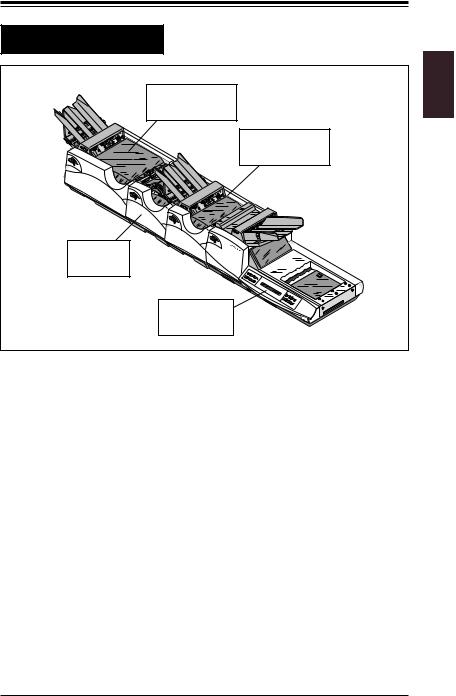
The simplest configuration for a FastPac™ Inserting System DI800 is a Base Unit and one feeding module, such as an Insert Feeder. More elaborate configurations are possible to fill a wide range of needs. The illustration on the next page shows a simple FastPac™ Inserting System DI800. The modules shown, a Sheet Feeder, Folder, Insert Feeder, and Base Unit are all explained in this manual.
Chapter 1: Introduction |
1-3 |
Introduction |
|
Single Sheet |
|
Feeder (F583) |
|
Single Insert |
|
Feeder (F581) |
|
Folder |
|
(F582) |
|
Base Unit |
|
(F580) |
F500_029 |
Figure 1-1—A Simple FastPac™ Inserting System DI800 |
|
Complete FastPac™ Inserting System DI800s always include the F580 Base Unit. Which modules are included in addition to the Base Unit depends on your needs. A FastPac™ Inserting System DI800 can consist of any of the following modules, up to a total of five plus the Base Unit.
Base Unit (F580)—Every FastPac™ Inserting System DI800 must have the Base Unit. Consult Chapter 2 of this manual for a detailed explanation of the Base Unit. You can't operate the FastPac™ Inserting System DI800 without thoroughly understanding the Base Unit.
Insert Feeder—The F581 Single Insert Feeder (Chapter 3) and F587 Twin Insert Feeder (Appendix A) adds an insert to the collation that is inserted in the envelope by the Base Unit. The feeder is capable of feeding a wide variety of forms and materials by moving the paper along with a belt and gate system. The feeder holds material until the next module is ready to accept it.

1-4 |
Chapter 1: Introduction |
|
|
Introduction
Sheet Feeder—The F583 Single Sheet Feeder ( Chapter 3) and F588 Twin Sheet Feeder (Appendix A) can feed a supply of single sheets or collect a set (up to six sheets) from another module. The sheet feeder passes a complete set to the next module (usually a folder).
OMR capability—The F504/F516 OMR is an optional feature, that can be attached to either the F581 Single Insert Feeder or the F583 Single Sheet Feeder (Chapter 3). The OMR option continuously scans enclosures as they leave a feeder deck. If an End of Collation (EOC) mark is recognized, it passes the collation to the next downstream module for processing.
Folder (F582)—The Folder (Chapter 4) is included in a system to accept paper (from one to six sheets) from upstream modules, fold it into one of four common folds (single fold, letter fold, accordion fold, or double fold) and pass it downstream to the Base Unit. The folder also has a bypass mechanism to let paper pass through the folder if you do not want the paper folded.
Cross Folder (F407)—The Cross Folder (Chapter 5) handles large pieces of paper by single folding a sheet once and then changing the direction of the paper so that a second fold module can fold it again.
Different “input devices” such as bursters and cutters can also be added to the FastPac™ Inserting System DI800. These attach to the FastPac™ Inserting System DI800 at the opposite end from the Base Unit, at the furthest upstream point, to feed special forms into the FastPac™ Inserting System DI800. The F422 Burster Interface is covered in Chapter 6. The 3324 Burster is covered in SV40025.
Chapter 1: Introduction |
1-5 |
|
|
|
|
Introduction
Components do not have to be in a specific order, but logically, certain functions must follow other functions (i.e., sheets must be fed before they can be folded, and they need to be folded before they can fit in an envelope).
As paper moves through the FastPac™ Inserting System DI800 we say it is flowing “downstream.” The Base Unit is always located at the most downstream position, the position all the way to the right when facing the operator side of the machine (the side with the control panels). The furthest upstream module, usually a sheet feeder, is all the way to the left.
In many of the messages displayed on the main control panel on the Base Unit, modules are referred to by number. These are the numbers that the FastPac™ Inserting System DI800 assigns to each module based on its position in the system. The Base Unit is not numbered and the most upstream module is always number one. The numbers increase as you move downstream toward the Base Unit. See Figure 1-2 below.
Sheet Feeder |
|
Insert |
Base Unit |
Folder |
Feeder |
||
Module |
Module |
Module |
The Base Unit is |
Number 1 |
Number 2 |
Number 3 |
Not Numbered |
UPSTREAM |
|
|
DOWNSTREAM |
Figure 1-2—Paper flows downstream

1-6 |
Chapter 1: Introduction |
|
|
Introduction
Additional capabilities include Fold Only, Daily Mail, Continuous/Batching stacking modes, and Double Detect reference methods.
•Fold Only allows you to process material through the FastPac™ Inserting System DI800, but not insert it into an envelope.
•Daily Mail is a feature which allows you to interrupt a job to process a small job, and then go back to the original job. Note that new setup may be required for the Daily Mail and then a return to the original setup.
•Continuous/Batching stacking modes allow you to process one piece after another (Continuous), a counter counting continuously, or in batches of 25 with a counter counting the batches from 25 down to zero (Maximum batch count is 250).
•Double Detection can be set up on Start where thickness of the first piece through is measured and then used as a reference for subsequent sheets. It can also be set up by using the Trial Piece method. In Trial Piece, the envelope is not sealed, allowing you to examine the collation to be sure it is correct.

Chapter 1: Introduction |
1-7 |
|
|
|
|
Safety
The Tabletop Inserting System is equipped with safety interlocks that prevent operation under certain circumstances. Never attempt to defeat these devices; you’ll endanger yourself and co-workers.
•Keep loose clothing, jewelry, and long hair away from all moving parts.
•Avoid touching moving parts or materials while machine is in use. Before clearing a jam, be sure mechanisms come to a stop.
•When removing jammed material, avoid using too much force to protect against minor personal injury and damaging equipment.
•Use the power cord supplied with the machine and plug it into an easily accessible, properly grounded wall outlet located near the machine. Failure to properly ground the machine can result in severe personal injury and /or fire.
•The power cord is the primary means of disconnecting the machine from the AC supply.
•DO NOT use an adapter plug on the line cord or wall outlet.
•DO NOT remove the ground pin from the line cord.
•Avoid using wall outlets that are controlled by wall switches or shared with other equipment.
•DONOTroute the power cordover sharp edges or trapit between furniture.
•Ensure there is no strain on the power cord where it becomes jammed between the equipment, walls, or furniture.
•Be sure the area in front of the wall receptacle into which the machine is plugged is free from obstruction.
•Do not remove covers. Covers enclose hazardous parts that should only be accessed by Pitney Bowes Customer Service. Report any damage of covers to your Pitney Bowes Customer Service representative.
•To prevent overheating, do not cover the vent openings.
•Read all instructions before attempting to operate the equipment.
•Use this equipment only for its intended purpose.
In addition, follow any specific occupational safety and health standards for your workplace or area.

1-8 |
Chapter 1: Introduction |
|
|
A Note to the Operator
The instructions in this guide explain how to set up and use the modules in a basic FastPac™ Inserting System DI800. Being familiar with the information in this manual helps you keep problems to a minimum and achieve the best possible performance from your system.
Before setting up and using the system, you should be completely familiar with the modules used in your application. Read each chapter of this manual as your system may include any of the available modules. This operating guide is meant to help you use the equipment to its full potential. For additional assistance, contact your Pitney Bowes Customer Service Representative.
Note that some of the instructions that follow tell you to use the scales provided on the FastPac™ Inserting System DI800 to take measurements. Always use these scales as instructed.

Chapter 1: Introduction |
1-9 |
|
|
|
|
Material Specifications
These material specifications apply to the FastPac™ Inserting System DI800.
Envelopes for the F580 Base Unit:
•Envelopes must be flat, straight, and not glued together.
•Envelopes can be standard side seam, diagonal side seam, executive, die cut, and closed window. The FastPac™ Inserting System DI800 does not run open window envelopes.
•Envelopes must be made from at least 16 lb. bond and no more than 24 lb. bond material.
•Maximum acceptable envelope size is 6-7/16" (163mm) deep by 10-3/8" (263mm) wide.
•Minimum acceptable envelope size is 3-1/2" (89mm) deep by 6-3/8" (162mm) wide.
•Flaps must be between 1-1/4" (32mm) and 2-1/4" (57mm) and all envelopes must always have at least 1/4" (7mm) clearance on each side, and a 1/4" (7mm) clearance between the crease line of the flap and the edge of the insert.
Material for other system modules:
•Sheets for the F583 and F588 Sheet Feeder must be at least 5-1/2" (140mm) wide and no more than 9-7/8" (250mm) wide.
•Sheets for the F583 and F588 Sheet Feeder must be at least 4" (102mm) deep, but no more than 14" (355mm) deep.
•Sheets must be made from at least 16 lb. bond and no more than 24 lb. bond material.

1-10 |
Chapter 1: Introduction |
|
|
Material Specifications
•The thickness of the full collation feeding through the sheet feeder must not exceed .072" (2.0mm). If sheets are to be folded, thickness must not exceed .024" (0.6mm) or 6 sheets.
•Inserts for the F581 and F587 Insert Feeder must be at least 5-1/2" (140mm) wide and no more than 9-7/8" (250mm) wide.
•Inserts for the F581 and F587 Insert Feeder must be at least 2- 1/2" (64mm) deep, but no more than 6" (152mm) deep.
•Insert thickness must not exceed .100" (2.5mm).
•The depth of all material must be within 1/2" (12mm) of each other in the accumulator section of the Insert Feeder.
•The depth of all inserts must be within 1/2" (12mm) of the depth of a folded sheet.
•The folder is limited to six sheets of 20 lb. bond, or if the fold desired is a Double Fold, then only 3 sheets may be folded.
•If input includes a crossfolded document, only a single sheet may be added before the fold is made.
•Material to be fed and read by an OMR kit installed on an F583 and F588 Sheet Feeder is a single sheet of material within the specification of the F583 and F588 Sheet Feeder.
•If the OMR is installed on an F581 and F587 Insert Feeder, depth and width of material is the same as specified for F581 and F587.
•The thickness of the material when scanning cannot exceed
.020" (0.5mm). The thickness when not scanning can reach
.100" (2.5mm).

Chapter 2: The Base Unit
Overview
The F580 Base Unit is the primary and required component of the FastPac™ Inserting System DI800. The primary functions of the Base Unit are to insert the collation into an envelope, process that envelope, and control the system from commands entered at the Main Control Panel.
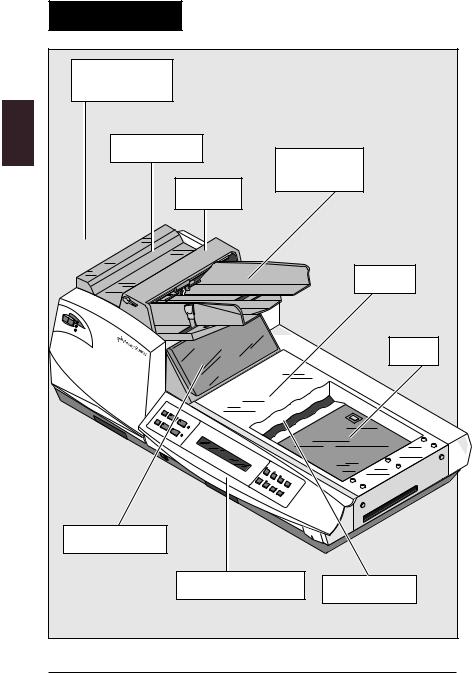
The Base Unit consists of several main sections; see Figure 2-1, next page:
•the envelope feeder
•the flapper
•the insert station
•the turner/ejection station
•the sealer
•the Main Control Panel
Other modules in the system are always located to the left (or “upstream”) of the Base Unit. Paper flows from these modules toward the Base Unit—often referred to as flowing “downstream”— flowing toward the Base Unit.
WARNING: As we've stated, the Base Unit is just one component of the entire FastPac™ Inserting System DI800. Each module was “docked” to the other
!modules in the system by your service representative when it was installed.
Never attempt to separate the modules. This is for service personnel only.
2-2 |
Chapter 2: The Base Unit |
|
|
|
|
Overview |
|
|
|
|
|
Incoming |
|
|
|
|
|
Collation Path |
|
|
|
|
|
Flapper Area |
|
|
|||
|
|
|
|
Envelope |
|
|
|
|
|
Feeder |
|
|
|
|
Bridge |
|
|
|
|
|
|
|
Turner |
|
|
|
|
|
Sealer |
Reset/ |
|
|
|
|
|
Review |
|
|
|
|
|
|
Trial |
Piece |
|
|
|
|
|
|
|
||
JJob |
|
|
Start |
|
|
Pause |
|
|
Add |
|
|
|
|
|
Water |
|
|
|
|
Clear |
Deck |
|
|
|
|
|
|
|
|
|
|
|
Seal |
|
|
|
|
|
Setup |
|
|
|
|
|
|
Report |
|
|
|
|
Exit |
|
|
|
|
|
Zero |
Count |
|
|
|
|
|
|
|
Insert Station |
|
|
|
|
|
|
|
|
Main Control Panel |
Eject Station |
|
|
|
|
|
|
|
|
|
|
|
|
F500_043 |
Figure 2-1—The Base Unit (F580) |
|
|
|||

Chapter 2: The Base Unit |
2-3 |
|
|
|
|
Overview
The following describes how paper moves through the Base Unit.
•The envelope feeder holds a supply of envelopes and feeds them to the flapper area of the Base Unit. Like the feeder modules described later, the envelope feeder has a separating mechanism that separates individual envelopes from the stack loaded in the feeder. The separating mechanism peels them away, one at a time, from the stack and feeds them down to the paper path.
•The flapper section of the Base Unit opens the flap on the envelope. As the envelope feeds into the flapper, the lead edge of the envelope, opposite the flap edge, enters a pair of rollers. The bottom roller rotates, wrapping the envelope around until the downstream edge of the envelope contacts the flap openers. As the envelope continues to move, the flap openers pull the flap away from the body of the envelope. Once the flap is pulled open, the envelope enters the insert station where a sensor detects its arrival. Another sensor detects if the flap is open.
•In the insert station the envelope throat is opened to receive the collation being fed from upstream modules. Three throat openers (two located on either side of the envelope and one in the center), are rotated into the throat of the envelope, pulling the envelope open to receive a collation. When the body of the envelope is open to receive the collation, a signal is sent that the envelope is ready, and the collation is fed from the upstream module into the open envelope.
continued-->

2-4 |
Chapter 2: The Base Unit |
|
|
|
|
Overview
•A sensor verifies that the collation is inserted, causing the Base Unit to pass the filled envelope to the turner section where it is rotated 90˚. As the mailpiece exits the insert station, the turner stops are raised to stop the mailpiece in the turner area. When the leading edge of the mailpiece hits the stops at the downstream end of the turner, the envelope stops and is turned 90° to be properly aligned for the sealer.
•Defective pieces are ejected by an eject mechanism. This provides a way to sort out unstuffed envelopes or incomplete collations. Ejection is done just after the insert station, preventing the mailpiece from being turned, sealed, and counted.
•The turned envelope feeds into the sealer where the flap is guided back toward a partially closed position and then passed over a moistener where moisture is applied to the glue on the flap. The envelope then passes through a pair of rollers that apply pressure to the wet, gummed surface of the envelope flap, sealing the envelope. When you select the no-seal option, the diverter prevents the flap from passing over the moistener.
A drawer pulls out of the front of the Base Unit for adding water to the sealer. A mechanical float is located in the reservoir to indicate the water level and help avoid over filling. A light on the Main Control Panel warns when the water level is low.
•The Base Unit also houses the Main Control Panel with the operator interface for all the modules in the system; these are the buttons you use to perform electronic setup on the entire FastPac™ Inserting System DI800.
•The On/Off power switch is also located on the front of the Base Unit. This controls power for the entire system.
Chapter 2: The Base Unit |
2-5 |
|
|
|
|
Controls and Indicators
Controls and indicators on the Base Unit are described next. Each illustration is labeled with numbers pointing out specific items in the picture. An explanation of how the numbered control works or what the indicator shows you is provided below the illustration.
Review these descriptions before you go on to the setup instructions that follow. Understanding where everything on the equipment is located will help you keep your FastPac™ Inserting System DI800 running smoothly and help you set the machine properly to get the most from it.
This section of the chapter is intended to show you where things are, not necessarily how to use them. Study the illustrations to see where things are located and use the section on Setup and Adjustments to learn how to operate the controls.
2-6 |
Chapter 2: The Base Unit |
|
|
|
|
Controls and Indicators
|
Re |
|
|
|
|
Reviseewt/ |
|
|
|
|
Trial |
|
|
|
|
Piece |
|
|
|
3 |
JJob |
|
|
Start |
Pause |
|
|
WAddater |
|
|
|
|
||
Clear |
De |
ck |
|
|
|
|
Seal |
||
|
|
|
|
Setup |
|
|
|
|
Report |
|
|
|
|
Exit |
|
|
|
|
Zero C |
|
|
|
|
ount |
|
1 |
|
|
|
|
2 |
|||
|
|
|
|
F500_043 |
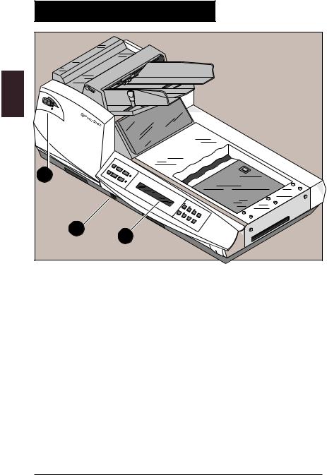
Figure 2-2—Major Controls |
||||
1.Power Switch—A rocker switch that controls power to the Base Unit and the entire FastPac™ Inserting System DI800.
2.Main Control Panel—The Main Control Panel has fourteen push buttons on the keypad, two status lights, and a display screen. Use the keys to perform setup for the Base Unit and the entire FastPac™ Inserting System DI800. If the LED on a key is lit, that function is available; if the LED is dark, that function is not currently available.
3.Mini Control Panel—A small control panel ( located on each of the FastPac™ Inserting System DI800 modules) which indicates if the module is on or off, ready, or has a fault. Use this control panel to run a single trial piece through a specific
module.
Chapter 2: The Base Unit |
2-7 |
|
|
|
|
Controls and Indicators
1 |
2 |
3 |
4 |
|
Review |
Trial Piece |
Start |
Add |
|
Water |
||||
|
|
|
||
Job |
Stop |
Clear Deck |
Seal |
|
|
|
|
5 |
6 |
7 |
8 |
F400_096
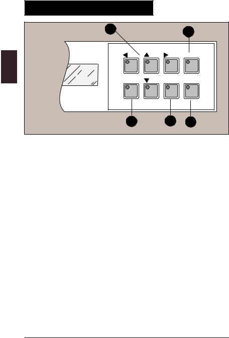
Figure 2-3—Main Control Panel, Left Side of Display
1.Review—Press for module-by-module review of the system settings for the selected job.
2.Trial Piece—Press to assemble one complete inserted mailpiece for inspection. The mailpiece will be ejected.
3.Start—Press to start continuous processing.
4.Add Water Light—Lights when the sealer requires more water or sealing solution.
5.Job—Press to change the selected job. Press as many times as needed to display the desired job number. Up to ten different jobs (groups of electronic setup commands) can be stored.
6.Stop—Press to halt the system.
7.Clear Deck—Always press before turning off the machine to end a run or a job. The machine will cycle until all pieces on the transport deck have been fully assembled, inserted and stacked. Only pieces needed to complete collations will feed so that the deck is clean when the machine stops.
8.Seal Light—Lights when the seal option is activated.
2-8 |
Chapter 2: The Base Unit |
|
|
|
|
Controls and Indicators
1 |
|
2 |
|
|
|
|
|
Report |
Setup |
Exit |
Zero Count |
3 |
4 |
5 |
Figure 2-4—Main Control Panel, Right Side of Display
1.Arrow Keys—Use as indicated on the display to move from one choice to another or to make a selection.
2.Report—Press to display the current reading of the cumulative counter. The cumulative counter keeps track of the number of valid collations (pieces of mail) processed by the system. The count is independent and not affected by the Zero Count key (see below). You can use the cumulative counter as a general purpose counter to track the daily piece count, an operator piece count, or as a backup to the job counter.
3.Setup—After the job number you want is displayed on the screen, press this key to enter the setup mode, then use the arrow keys. A code is required to access the job setup functions.
4.Exit—Press to exit the setup mode.
5.Zero Count—Press to reset the piece counter to zero, e.g., at the beginning of a new job or run.

Chapter 2: The Base Unit |
2-9 |
|
|
|
|
Controls and Indicators
5
3
Trial Piece In Service
2
 Ready
Ready
 Fault
Fault
4 1
F500_030
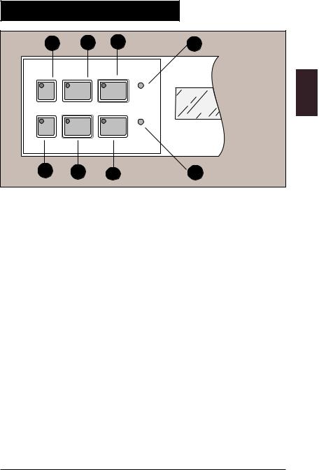
Figure 2-5—Mini Control Panel
1.Fault Light—Lights to indicate a fault has occurred at this module.
2.Ready Light—Lights to indicate the module is ready for operation.
3.In Service Light—Lights to indicate if the module is in service, that is on, for the job being run.
4.In Service Control—Press this key to take the module in and out of service (i.e., turns the feeder function on and off). The unit is in service when the light (Item 3 above) is illuminated. Turn the module off when using Fold Only mode (documents not inserted into envelope, but material will still pass through).
5.Trial Piece—Press this key to cycle the module once.

2-10 |
Chapter 2: The Base Unit |
|
|
|
|
Controls and Indicators
|
4 |
|
|
3 |
1 |
5 |
|
|
|
|
2 |
Trial |
Piece |
|
|
|
|
|
|
|
|
||
|
In S |
|
|
|
|
|
ervice |
|
|
|
|
|
Ready |
|
|
|
|
|
Fault |
|
|
|
|
|
|
R |
ese |
|
|
|
R |
|
|
||
|
|
eviewt/ |
|
|
|
|
|
|
|
Tri |
|
|
|
|
|
al Pi |
|
|
|
|
|
ece |
|
|
JJob |
|
|
Start |
|
|
P |
ause |
|
|
|
|
|
A |
|
||
|
|
W dd |
|
||
|
|
|
|
ater |
|
|
|
|
|
Cl |
|
|
|
|
|
ear D |
|
|
|
|
|
eck |
|
|
|
|
|
Seal |
|
F500 |
|
|
|
|
|
Figure 2-6—Envelope Feeder |
|
|
|
|
|
1.Envelope Feeder—Holds supply of envelopes.
2.Feeder Guides—Adjust these guides to hold the envelopes in place as they feed down to the deck.
3.Feeder Guides Lock Lever—Blue lever pushes in to release side guides so they can be adjusted.
4.Envelope Feeder Bridge—The piece that covers the separator gap. The main feed roller is located below this bridge.
5.Roller Release Lever—This is used to access paper under the
Main feed roller.

Chapter 2: The Base Unit |
2-11 |
|
|
|
|
Controls and Indicators
3 |
|
1 |
2 |
|
|
|
F500_048 |
Figure 2-7—Stone and Shield
1.Envelope Feeder Stone—Works with the Main Feed Roller to create the necessary friction for peeling one envelope at a time away from the stack in the envelope feeder.
2.Envelope Feeder Stone Shield—Adjust to reveal more or less of the stone.
3.Envelope Feeder Stone Shield Adjuster—Slide back and forth to adjust the amount of shield which affects how much friction is used to feed envelopes.

2-12 |
Chapter 2: The Base Unit |
|
|
|
|
Controls and Indicators
|
|
|
1 |
|
|
Re |
|
|
|
|
Reviseewt/ |
|
|
|
|
|
Trial |
|
|
|
|
Piece |
|
|
JJob |
|
|
Start |
|
|
Pause |
|
WAddater |
|
|
|
|
|
|
|
|
Clear |
Deck |
|
|
|
|
|
|
|
|
|
Seal |
|
|
|
|
Setup |
3 |
|
|
|
|
|
|
|
|
|
Report |
|
|
|
Exit |
|
|
|
|
Zero |
Count |
|
|
|
|
|
2 |
|
|
|
|
F550_010 |
|
|
|
|
Figure 2-8—Separating Mechanism |
||||
1.Envelope Feeder Prefeed Rollers—Help move one envelope to the separating stone and main feed roller.
2.Envelope Feeder Main Feed Rollers—Move envelopes one at a time down from the feeder to the flapper.
3.Separator Gap Adjustment Wheel—Raises and lowers the main feed rollers to adjust the “separating gap.” To adjust for better separation, turn the adjustment wheel clockwise to raise
the rollers and counterclockwise to lower them.

Chapter 2: The Base Unit |
2-13 |
Controls and Indicators
3 |
1 |
2 |
4 |
Figure 2-9—Envelope Flapper Unit
1.Envelope Flapper Unit Safety Cover—Flip open to access envelope flapper unit to remove envelope misfeeds.
2.Envelope Flapper Cover Lock Lever—Pull this lever to release flapper unit. Flapper unit gently pivots when unlocked.
3.Recessed Area on Flapper Unit—Pull here after flapper unit is unlocked to expose more of the flapper unit.
4.Tab on Flapper Unit—Pull here to gain access to the inside of the flapper.

2-14 |
Chapter 2: The Base Unit |
|
|
|
|
Controls and Indicators
2 |
0 |
|
|
|
110 |
100 |
|
|
|
|
|
|
2 |
|
|
|
1 |
|
|
|
|
|
90 |
|
0 |
|
|
|
3 |
|
|
|
1 |
|
|
0 |
|
|
|
1 |
|
|
|
2 |
0 |
|
|
|
|
|
|
3 |
4 |
|
|
1 |
|
|
|
4 |
|
|
1 |
|
|
6 |
|
|
|
150 |
0 |
|
|
|
|
190 |
|
|
|
180 |
|
|
|
170 |
|
|
|
3
Review
Trial
1
F400_133
Figure 2-10—Insert Station Envelope Side Guides
1.Envelope Side Guides—Guides in the insert area that hold the envelope in place after it’s opened. The two guides keep the envelope lined up with the oncoming mailpiece for insertion (only one guide is visible here).
2.Envelope Side Guides Setting Knob—Small blue knob located on the side frame of the module, under the cover. Turn the knob to move the scale until the pointer indicates the measured width of the envelope.
3.Scale and Pointer—Match the pointer to the measured width
of the envelope on the scale.
 Loading...