

Pioneer VSX-916 Owners manual

VSX-916-S/-K
AUDIO/VIDEO MULTI-CHANNEL RECEIVER
SINTOAMPLIFICATORE AUDIO/VIDEO
MULTICANALE
Discover the benefits of registering your product online at www.pioneer.co.uk
(www.pioneer-eur.com).
Registra il tuo prodotto su www.pioneer.it (o www.pioneer-eur.com)
e scopri subito quali vantaggi puoi ottenere!
Operating Instructions
Istruzioni per l’uso
IMPORTANT
CAUTION
RISK OF ELECTRIC SHOCK
DO NOT OPEN
The lightning flash with arrowhead symbol,
within an equilateral triangle, is intended to
alert the user to the presence of uninsulated
"dangerous voltage" within the product's
enclosure that may be of sufficient
magnitude to constitute a risk of electric
shock to persons.
Replacement and mounting of an AC plug on the power supply cord of this unit should be performed only by qualified
service personnel.
IMPORTANT: THE MOULDED PLUG
This appliance is supplied with a moulded three pin mains plug for your safety and convenience. A 5 amp fuse is fitted in this plug. Should the
fuse need to be replaced, please ensure that the replacement fuse has a rating of 5 amps and that it is approved by ASTA or BSI to BS1362.
Check for the ASTA mark or the BSI mark on the body of the fuse.
If the plug contains a removable fuse cover, you must ensure that it is refitted when the fuse is replaced. If you lose the fuse cover the plug
must not be used until a replacement cover is obtained. A replacement fuse cover can be obtained from your local dealer.
If the fitted moulded plug is unsuitable for your socket outlet, then the fuse shall be removed and the plug cut off and disposed of
safely. There is a danger of severe electrical shock if the cut off plug is inserted into any 13 amp socket.
If a new plug is to be fitted, please observe the wiring code as shown below. If in any doubt, please consult a qualified electrician.
IMPORTANT: The wires in this mains lead are coloured in accordance with the following code:
Blue : Neutral Brown : Live
As the colours of the wires in the mains lead of this appliance may not correspond with the coloured markings identifying the terminals in
your plug, proceed as follows ;
The wire which is coloured BLUE must be connected to the terminal which is marked with the
letter N or coloured BLACK.
The wire which is coloured BROWN must be connected to the terminal which is marked with the
letter L or coloured RED.
How to replace the fuse: Open the fuse compartment with a screwdriver and replace the fuse.
CAUTION:
TO PREVENT THE RISK OF ELECTRIC
SHOCK, DO NOT REMOVE COVER (OR
BACK). NO USER-SERVICEABLE PARTS
INSIDE. REFER SERVICING TO QUALIFIED
SERVICE PERSONNEL.
The exclamation point within an equilateral
triangle is intended to alert the user to the
presence of important operating and
maintenance (servicing) instructions in the
literature accompanying the appliance.
D3-4-2-1-1_En-A
D3-4-2-1-2-2_B_En
Thank you for buying this Pioneer product.
Please read through these operating instructions so
you will know how to operate your model properly.
After you have finished reading the instructions, put
them away in a safe place for future reference.
WARNING
This equipment is not waterproof. To prevent a fire
or shock hazard, do not place any container filed
with liquid near this equipment (such as a vase or
flower pot) or expose it to dripping, splashing, rain
or moisture.
WARNING
Before plugging in for the first time, read the following
section carefully.
The voltage of the available power supply differs
according to country or region. Be sure that the
power supply voltage of the area where this unit
will be used meets the required voltage (e.g., 230V
or 120V) written on the rear panel.
D3-4-2-1-3_A_En
D3-4-2-1-4_A_En
WARNING
To prevent a fire hazard, do not place any naked
flame sources (such as a lighted candle) on the
equipment.
D3-4-2-1-7a_A_En
Operating Environment
Operating environment temperature and humidity:
+5 ºC – +35 ºC (+41 ºF – +95 ºF); less than 85 %RH
(cooling vents not blocked)
Do not install this unit in a poorly ventilated area, or in
locations exposed to high humidity or direct sunlight (or
strong artificial light)
This product complies with the Low Voltage Directive
(73/23/EEC, amended by 93/68/EEC), EMC Directives
(89/336/EEC, amended by 92/31/EEC and
93/68/EEC).
D3-4-2-1-7c_A_En
D3-4-2-1-9a_En
If you want to dispose this product, do not mix it with general household waste. There is a separate collection system for used
If you want to dispose this product, do not mix it with general household waste. There is a separate collection system for used
electronic products in accordance with legislation that requires proper treatment, recovery and recycling.
electronic products in accordance with legislation that requires proper treatment, recovery and recycling.
Private households in the 25 member states of the EU, in Switzerland and Norway may return their used electronic products free of charge to
Private households in the 25 member states of the EU, in Switzerland and Norway may return their used electronic products free of charge to
designated collection facilities or to a retailer (if you purchase a similar new one).
designated collection facilities or to a retailer (if you purchase a similar new one).
For countries not mentioned above, please contact your local authorities for the correct method of disposal.
For countries not mentioned above, please contact your local authorities for the correct method of disposal.
By doing so you will ensure that your disposed product undergoes the necessary treatment, recovery and recycling and thus prevent potential
By doing so you will ensure that your disposed product undergoes the necessary treatment, recovery and recycling and thus prevent potential
negative effects on the environment and human health.
negative effects on the environment and human health.
VENTILATION CAUTION
VENTILATION CAUTION
When installing this unit, make sure to leave space
When installing this unit, make sure to leave space
around the unit for ventilation to improve heat
around the unit for ventilation to improve heat
radiation (at least 60 cm at top, 10 cm at rear, and
radiation (at least 60 cm at top, 10 cm at rear, and
30 cm at each side).
30 cm at each side).
WARNING
WARNING
Slots and openings in the cabinet are provided for
Slots and openings in the cabinet are provided for
ventilation to ensure reliable operation of the
ventilation to ensure reliable operation of the
product, and to protect it from overheating. To
product, and to protect it from overheating. To
prevent fire hazard, the openings should never be
prevent fire hazard, the openings should never be
blocked or covered with items (such as newspapers,
blocked or covered with items (such as newspapers,
table-cloths, curtains) or by operating the
table-cloths, curtains) or by operating the
equipment on thick carpet or a bed.
equipment on thick carpet or a bed.
D
D
O
O
W
W
N
N
D
D
O
O
W
W
N
N
D3-4-2-1-7b_A_En
D3-4-2-1-7b_A_En
This product is for general household purposes. Any
This product is for general household purposes. Any
failure due to use for other than household purposes
failure due to use for other than household purposes
(such as long-term use for business purposes in a
(such as long-term use for business purposes in a
restaurant or use in a car or ship) and which
restaurant or use in a car or ship) and which
requires repair will be charged for even during the
requires repair will be charged for even during the
warranty period.
warranty period.
CAUTION
CAUTION
The STANDBY/ON switch on this unit will not
The STANDBY/ON switch on this unit will not
completely shut off all power from the AC outlet.
completely shut off all power from the AC outlet.
Since the power cord serves as the main disconnect
Since the power cord serves as the main disconnect
device for the unit, you will need to unplug it from
device for the unit, you will need to unplug it from
the AC outlet to shut down all power. Therefore,
the AC outlet to shut down all power. Therefore,
make sure the unit has been installed so that the
make sure the unit has been installed so that the
power cord can be easily unplugged from the AC
power cord can be easily unplugged from the AC
outlet in case of an accident. To avoid fire hazard,
outlet in case of an accident. To avoid fire hazard,
the power cord should also be unplugged from the
the power cord should also be unplugged from the
AC outlet when left unused for a long period of time
AC outlet when left unused for a long period of time
(for example, when on vacation).
(for example, when on vacation).
K041_En
K041_En
D3-4-2-2-2a_A_En
D3-4-2-2-2a_A_En
K058_En
K058_En
If the AC plug of this unit does not match the AC
If the AC plug of this unit does not match the AC
outlet you want to use, the plug must be removed
outlet you want to use, the plug must be removed
and appropriate one fitted. Replacement and
and appropriate one fitted. Replacement and
mounting of an AC plug on the power supply cord of
mounting of an AC plug on the power supply cord of
this unit should be performed only by qualified
this unit should be performed only by qualified
service personnel. If connected to an AC outlet, the
service personnel. If connected to an AC outlet, the
cut-off plug can cause severe electrical shock. Make
cut-off plug can cause severe electrical shock. Make
sure it is properly disposed of after removal.
sure it is properly disposed of after removal.
The equipment should be disconnected by removing
The equipment should be disconnected by removing
the mains plug from the wall socket when left
the mains plug from the wall socket when left
unused for a long period of time (for example, when
unused for a long period of time (for example, when
on vacation).
on vacation).
WARNING
Do not use or store batteries in direct sunlight or
Do not use or store batteries in direct sunlight or
other excessively hot place, such as inside a car or
other excessively hot place, such as inside a car or
near a heater. This can cause batteries to leak,
near a heater. This can cause batteries to leak,
overheat, explode or catch fire. It can also reduce the
overheat, explode or catch fire. It can also reduce the
life or performance of batteries.
life or performance of batteries.
WARNING
D3-4-2-2-1a_A_En
D3-4-2-2-1a_A_En
D3-4-2-3-3_En
D3-4-2-3-3_En
Manufactured under license from Dolby
Manufactured under license from Dolby
Laboratories. "Dolby", "Pro Logic",
Laboratories. "Dolby", "Pro Logic",
"Surround EX", and the double-D symbol
"Surround EX", and the double-D symbol
are trademarks of Dolby Laboratories.
are trademarks of Dolby Laboratories.
"DTS" ,"DTS-ES" ,"DTS 96/24" and
"DTS" ,"DTS-ES" ,"DTS 96/24" and
"Neo:6" are trademarks of Digital Theater
"Neo:6" are trademarks of Digital Theater
Systems, Inc.
Systems, Inc.

Contents
01 Before you start
Checking what’s in the box
Loading the batteries
Installing the receiver
Ventilation
. . . . . . . . . . . . . . . . . . . . . . . . . . . . 6
. . . . . . . . . . . . . . . 6
. . . . . . . . . . . . . . . . . . . 6
. . . . . . . . . . . . . . . . . . . 6
02 5 minute guide
Introduction to home theater
Listening to Surround Sound
Using the Quick Setup
. . . . . . . . . . . . . 7
. . . . . . . . . . . . . 7
. . . . . . . . . . . . . . . . . . 8
03 Quick surround sound setup
Automatically setting up for surround sound
(MCACC)
. . . . . . . . . . . . . . . . . . . . . . . . . . . . . 9
Other problems when using the Auto
MCACC Setup
. . . . . . . . . . . . . . . . . . . . . . 11
04 Connecting up
Making cable connections
Analog audio cables
Digital audio cables
Video cables
Connecting a DVD player and TV
Connecting the multichannel analog
outputs
Connecting a satellite receiver or other
digital set-top box
Connecting other audio components
About the WMA9 Pro decoder
Connecting other video components
Using the component video jacks
Connecting to the front panel video
terminal
Connecting antennas
Using external antennas
Connecting the speakers
Hints on speaker placement
. . . . . . . . . . . . . . . . . . . . . . . . 12
. . . . . . . . . . . . . . . . . . . . . . . . . . . . 14
. . . . . . . . . . . . . . . . . . . . . 14
. . . . . . . . . . . . . . . . . . . . . . . . . . . 17
. . . . . . . . . . . . . . 12
. . . . . . . . . . . . . . . . . . 12
. . . . . . . . . . . . . . . . . . 12
. . . . . . . . . 13
. . . . . . 15
. . . . . . . . . . 15
. . . . . . 16
. . . . . . . . 17
. . . . . . . . . . . . . . . . . . 18
. . . . . . . . . . . . . . . 18
. . . . . . . . . . . . . . . 19
. . . . . . . . . . . . 20
05 Controls and displays
Front panel
Display
Remote control
Operating range of remote control
. . . . . . . . . . . . . . . . . . . . . . . . . . 22
. . . . . . . . . . . . . . . . . . . . . . . . . . . . . 23
. . . . . . . . . . . . . . . . . . . . . . . 25
. . . . . . . 27
06 Listening to your system
Auto playback
Listening in surround sound
Using the Advanced surround effects
. . . . . . . . . . . . . . . . . . . . . . . . 28
. . . . . . . . . . . . . 28
. . . . 29
Setting the effect options
Listening in stereo
Listening with Acoustic Calibration EQ
Using surround back channel processing
Using Virtual Surround Back (VSB)
Using Midnight and Loudness
Using the Sound Retriever
Enhancing dialog
Using the tone controls
Playing other sources
Choosing the input signal
Selecting the multichannel analog inputs
. . . . . . . . . . . . . . . . . . . . . 32
. . . . . . . . . . . . . . 29
. . . . . . . . . . . . . . . . . . . . . 30
. . . . . 30
. . . 31
. . . . . . . 31
. . . . . . . . . . . . 32
. . . . . . . . . . . . . . . 32
. . . . . . . . . . . . . . . . . 32
. . . . . . . . . . . . . . . . . . 33
. . . . . . . . . . . . . . . 33
. . . 33
07 USB playback
Using the USB interface
Basic playback controls
Compressed audio compatibility
. . . . . . . . . . . . . . . . 34
. . . . . . . . . . . . . . . . . 34
. . . . . . . . . 35
08 The System Setup menu
Making receiver settings from the System
Setup menu. . . . . . . . . . . . . . . . . . . . . . . . . . 36
Surround back speaker setting . . . . . . . . . . . 36
Manual MCACC speaker setup . . . . . . . . . . . 37
Fine Channel Level . . . . . . . . . . . . . . . . . . . 38
Fine Speaker Distance . . . . . . . . . . . . . . . . 38
Acoustic Calibration EQ . . . . . . . . . . . . . . . 39
Manual speaker setup . . . . . . . . . . . . . . . . . . 41
Speaker Setting . . . . . . . . . . . . . . . . . . . . . 42
Crossover Network . . . . . . . . . . . . . . . . . . . 43
Channel Level . . . . . . . . . . . . . . . . . . . . . . . 43
Speaker Distance . . . . . . . . . . . . . . . . . . . . 44
09 Using the tuner
Listening to the radio. . . . . . . . . . . . . . . . . . . 45
Improving FM stereo sound . . . . . . . . . . . . 45
Tuning directly to a station . . . . . . . . . . . . . 45
Saving station presets . . . . . . . . . . . . . . . . . . 46
Naming station presets. . . . . . . . . . . . . . . . 46
Listening to station presets. . . . . . . . . . . . . 46
An introduction to RDS . . . . . . . . . . . . . . . . . 47
Displaying RDS information . . . . . . . . . . . . 47
Searching for RDS programs . . . . . . . . . . . 47
Using EON . . . . . . . . . . . . . . . . . . . . . . . . . . 48
10 Making recordings
Making an audio or a video recording . . . . . . 49

11 Controlling the rest of your
system
Operating other Pioneer components
Setting the remote to control other
components
Selecting preset codes directly
Programming signals from other remote
controls
Erasing one of the remote control button
settings
Erasing all of the remote control presets
Direct function
Confirming preset codes
Multi Operation and System Off
Programming a multi-operation or a
shutdown sequence
Using multi operations
Using System off
Controls for TVs
Controls for other components
. . . . . . . . . . . . . . . . . . . . . . . . . 50
. . . . . . . . . . . . . . . . . . . . . . . . . . . . . 51
. . . . . . . . . . . . . . . . . . . . . . . . . . . . . 52
. . . . . . . . . . . . . . . . . . . . . . . 53
. . . . . . . . . . . . . . . . 53
. . . . . . . . . . . . . . . . . . 54
. . . . . . . . . . . . . . . . 55
. . . . . . . . . . . . . . . . . . . . . 55
. . . . . . . . . . . . . . . . . . . . . . . 55
. . . . . . 50
. . . . . . . . . . . 51
. . . . 53
. . . . . . . . . . 53
. . . . . . . . . . . 57
12 Other connections
Second Zone speaker B setup
Switching the speaker system
Bi-amping your front speakers
Bi-wiring your speakers
Connecting additional amplifiers
Using this receiver with a Pioneer plasma
display
. . . . . . . . . . . . . . . . . . . . . . . . . . . . . . 61
Using the SR+ mode with a Pioneer
plasma display
. . . . . . . . . . . . . . . . . . . . . . 62
. . . . . . . . . . . . 59
. . . . . . . . . . 59
. . . . . . . . . . . 60
. . . . . . . . . . . . . . . . . 60
. . . . . . . . . . 61
English Italiano Français
13 Other Settings
The Input Assign menu
The Other Setup menu
Dynamic Range Control Setup
Dual Mono Setup
LFE Attenuator Setup
SR+ Setup for Pioneer plasma displays
. . . . . . . . . . . . . . . . . 63
. . . . . . . . . . . . . . . . . 64
. . . . . . . . . . 64
. . . . . . . . . . . . . . . . . . . . 65
. . . . . . . . . . . . . . . . . 65
14 Additional information
Troubleshooting
Resetting the main unit
Switching the speaker impedance
Changing the TV format setting
Specifications
Power cord caution
Cleaning the unit
. . . . . . . . . . . . . . . . . . . . . . 66
. . . . . . . . . . . . . . . . . 68
. . . . . . . . . 68
. . . . . . . . . . . 68
. . . . . . . . . . . . . . . . . . . . . . . . 69
. . . . . . . . . . . . . . . . . . . . 70
. . . . . . . . . . . . . . . . . . . . . . 70
Nederlands
. . . 65
EspañolDeutsch
Before you start01
Chapter 1:
Before you start
Checking what’s in the box
Please check that you've received the following
supplied accessories:
• Setup microphone
• Remote control unit
• Dry cell batteries (AA size IEC R6) x2
• AM loop antenna
• FM wire antenna
• Warranty card
• These operating instructions
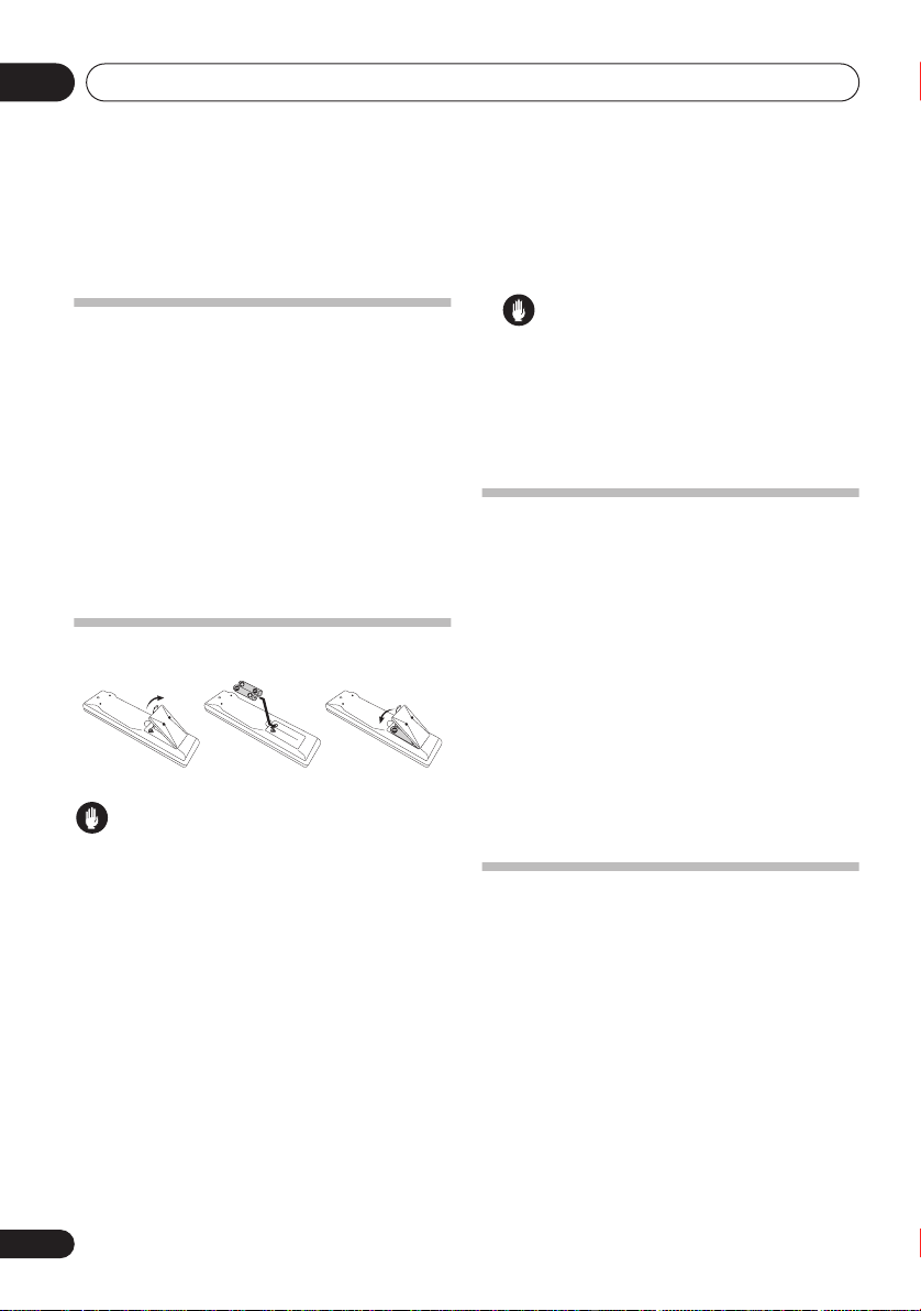
Loading the batteries
Caution
Incorrect use of batteries may result in such
hazards as leakage and bursting. Observe the
following precautions:
• Never use new and old batteries together.
• Insert the plus and minus sides of the
batteries properly according to the marks
in the battery case.
• Batteries with the same shape may have
different voltages. Do not use different
batteries together.
• When disposing of used batteries, please
comply with governmental regulations or
environmental public instruction’s rules
that apply in your country/area.
WARNING
• Do not use or store batteries in direct
sunlight or other excessively hot place,
such as inside a car or near a heater. This
can cause batteries to leak, overheat,
explode or catch fire. It can also reduce the
life or performance of batteries.
Installing the receiver
When installing this unit, make sure to put it on
a level and stable surface. Don’t install it on the
following places:
– on a color TV (the screen may distort)
– near a cassette deck (or close to a device that
gives off a magnetic field). This may interfere
with the sound.
– in direct sunlight
– in damp or wet areas
– in extremely hot or cold areas
– in places where there is vibration or other
movement
– in places that are very dusty
– in places that have hot fumes or oils (such as
a kitchen)
Ventilation
When installing this unit, make sure to leave
space around the unit for ventilation to
improve heat dispersal (at least 20 cm at the
top). If not enough space is provided between
the unit and walls or other equipment, heat will
build up inside, interfering with performance
and/or causing malfunctions.
Slot and openings in the cabinet are provided
for ventilation and to protect the equipment
from overheating. To prevent fire hazard, do not
place anything directly on top of the unit, make
sure the openings are never blocked or covered
with items (such as newspapers, table-cloths
and curtains), and do not operate the
equipment on thick carpet or a bed.
6
En
5 minute guide
02
Chapter 2:
5 minute guide
Introduction to home theater
Home theater refers to the use of multiple
audio tracks to create a surround sound effect,
making you feel like you're in the middle of the
action or concert. The surround sound you get
from a home theater system depends not only
on your speaker setup, but also on the source
and the sound settings of the receiver.
This receiver will automatically decode
multichannel Dolby Digital, DTS, or Dolby
Surround sources according to your speaker
setup. In most cases, you won’t have to make
changes for realistic surround sound, but
other possibilities (like listening to a CD with
multichannel surround sound) are explained in
Listening to your system
Listening to Surround Sound
With the following quick setup guide, you
should have your system hooked up for
surround sound in no time at all. In most
cases, you can simply leave the receiver in the
default settings.
• Be sure to complete all connections before
connecting to an AC power source.
1 Connect your DVD player and TV.
See
Connecting a DVD player and TV
to do this. For surround sound, you’ll want to
hook up using a digital connection from the
DVD player to the receiver.
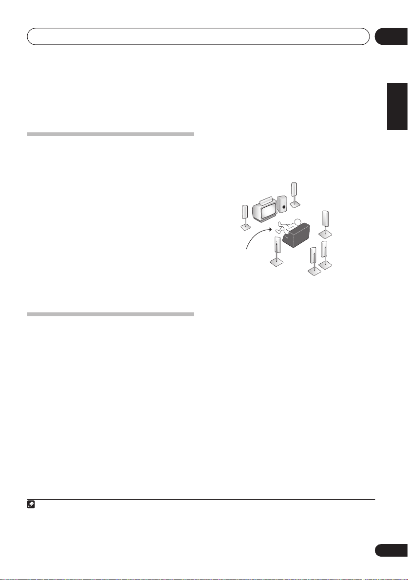
2 Connect your speakers and place them for
optimal surround sound.
See
Connecting the speakers
on page 28.
on page 13
on page 19.
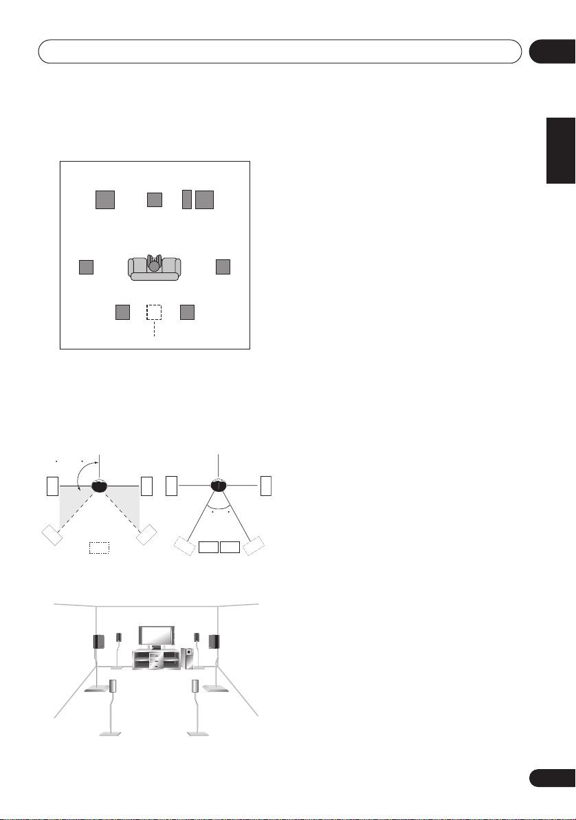
Where you place the speakers will have a big
effect on the sound. Place your speakers as
shown below for the best surround sound
effect. Also see
Hints on speaker placement
on
page 20 for more on this.
Front
speaker
(R)
Subwoofer (SW)
Surround back
speaker (SBL)
Surround
speaker (RS)
Surround
back
speaker (SBR)
Front
speaker
(L)
Listening
position
Center
speaker
(C)
Surround
speaker (LS)
3 Plug in and switch on the receiver, followed
by your DVD player, subwoofer and TV.
Make sure you’ve set the video input on your TV
to this receiver. Check the manual that came
with the TV if you don’t know how to do this.
4 Press QUICK SETUP on the front panel to
specify your speaker setup, room size and
listening position.
Use the
to confirm your selection. See
Setup
MULTI JOG
dial to select and
below for more on this.
ENTER
Using the Quick
5 Play a DVD, and adjust the volume.
Make sure that
receiver’s display. If it isn’t, press
remote to set the receiver to the DVD input.
DVD
is showing in the
DVD
on the
1
There are several other sound options you can
select. See
for more on this.
Listening to your system
2
on page 28
English
Deutsch
Français
Italiano
Nederlands
Español
Note
1 You may need to set your DVD player to output Dolby Digital, DTS and 88.2/96 kHz PCM (2 channel) audio (see your DVD player’s manual for more on this).
2 Depending on your DVD player or source disc, you may only get 2 channel sound. In this case, the listening mode must be set
STANDARD
to
(see
Listening in surround sound
on page 28 if you need to do this) if you want multichannel surround sound.
7
En
5 minute guide02
DIGITAL PRECISION
PROCESSING
Using the Quick Setup
You can use the Quick Setup to get your
system up and running with just a few button
presses. The receiver automatically makes the
necessary settings after you have selected your
speaker setup, room size and listening
position. Use the front panel controls for the
steps below.
• If you want a more complete setup option,
refer to
Automatically setting up for
surround sound (MCACC)
choose to do so, you can skip the Quick
1
Setup.
ADVANCED
STANDARD
STANDBY/ON
LISTENING MODE
ST/DIRECT/
SURR
AUTO SURR
PHONES
TV/SAT DVR/VCR
DVD/LD
PTY
EON
MIDNIGHT/
SEARCH
SPEAKERS
MODE
LOUDNESS
TUNING/
TUNER
TONE
STATION
EDIT
MULTI JOG
1 If the receiver is off, press
STANDBY/ON
2 Press
•
SW DET
to turn the power on.
QUICK SETUP
flashes in the display while the
receiver checks your setup for a subwoofer.
SW YES
or
SW NO
check, then the display prompts you to
select your speaker setup.
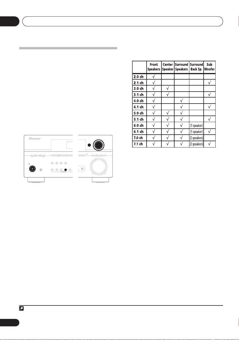
3 Use the
MULTI JOG
speaker setup.
When a subwoofer was detected in step 2, the
following choices are available:
2.1ch – 3.1ch – 4.1ch – 5.1ch – 6.1ch – 7.1ch
If a subwoofer wasn’t detected in step 2, you
can cycle between the following choices:
2.0ch – 3.0ch – 4.0ch – 5.0ch – 6.0ch – 7.0ch
on page 9. If you
AUDIO/ VID EO MULTI-CHANNEL RECEIVER
AUX
MCACC
SETUP MIC
QUICK
SETUP
SETUP
VSX-916
MULTI JOG
ENTER
ch
SIGNAL
SB
ACOUSTIC
PROCESSING
SELECT
EQ
MASTER
VOLUME
UPDOWN
.
confirms the subwoofer
dial to choose your
• Check the table below to find the speaker
setup that corresponds with your system.
4 Press
5 Use the
ENTER
.
MULTI JOG
dial to choose your
room size.
Depending on the distance of your speakers
from the listening position, choose between
small, medium, or large (
S, M
or L), M being an
average-sized room.
6 Press
7 Use the
ENTER
.
MULTI JOG
dial to choose your
listening position.
You can cycle between the following choices:
•
FWD
– If you are nearer to the front
speakers than the surround speakers
•
MID
– If you are equal distance from the
front and surround speakers
•
BACK
– If you are nearer to the surround
speakers than the front speakers
8 Press
ENTER
to confirm your setup.
The display shows the speaker setup, room size
and listening position that you have selected.
8
En
Note
1 See also
Making receiver settings from the System Setup menu
on page 36 for more setup options.
Quick surround sound setup
03
Chapter 3:
Quick surround sound setup
Automatically setting up for
surround sound (MCACC)
The Auto Multi-Channel Acoustic Calibration
(MCACC) setup measures the acoustic
characteristics of your listening area, taking
into account ambient noise, speaker size and
distance, and tests for both channel delay and
channel level. After you have set up the
microphone provided with your system, the
receiver uses the information from a series of
test tones to optimize the speaker settings and
equalization for your particular room.
Important
• The Auto MCACC Setup will overwrite any
existing speaker settings you’ve made.
• Make sure the headphones are unplugged.
Caution
• The test tones used in the Auto MCACC
Setup are output at high volume.
TOP MENU
SETUP
GUIDE
D.ACCESS
PTY SEARCH
TV VOL
DIALOG E
+10
TUNE
ST ST
ENTER
TUNE
TV CONTROL
INPUT
TV CH
SELECT
CLASS
DISC
ENTER
MENU
T.EDIT
RETURN
VOL
RECEIVER
AV PRE-PROGRAMMED AND LEARNING
REMOTE CONTROL UNIT
DVD
CD
SELECT
TV DVR
CD-R/TAPE
SOURCE
TV CTRL
USB
RECEIVER
AMFM
SYSTEM OFF
INPUT
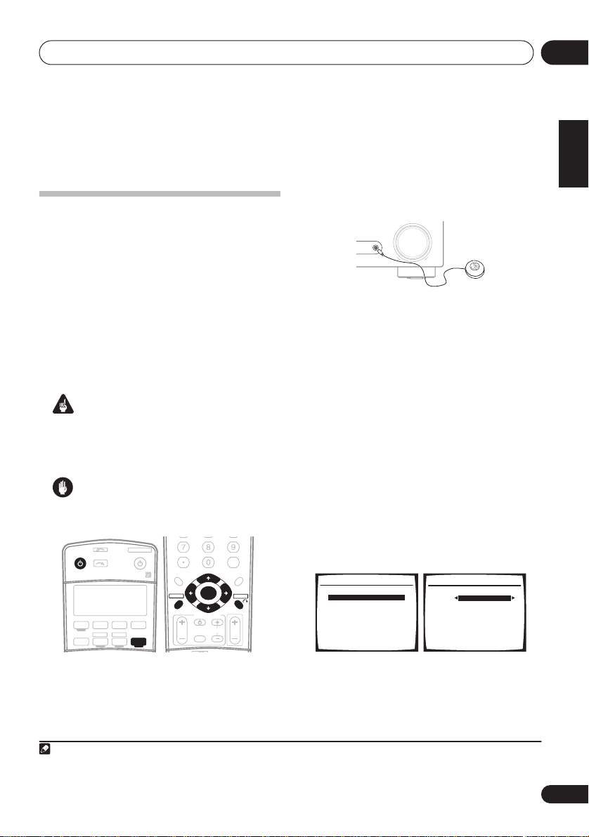
1 Switch on the receiver and your TV.
2 Connect the microphone to the MCACC
SETUP MIC
jack on the front panel.
Push down on the
the
MCACC SETUP MIC
If you have a tripod, use it to place the
microphone so that it’s about ear level at your
normal listening position. Otherwise, place the
microphone at ear level using a table or a chair.
• Make sure there are no obstacles between
the speakers and the microphone.
3 Press
RECEIVER
then press the
An on-screen display (OSD) appears on your
TV. Use
///
control to navigate through the screens and
select menu items. Press
current menu.
• Press
SETUP
Setup menu.
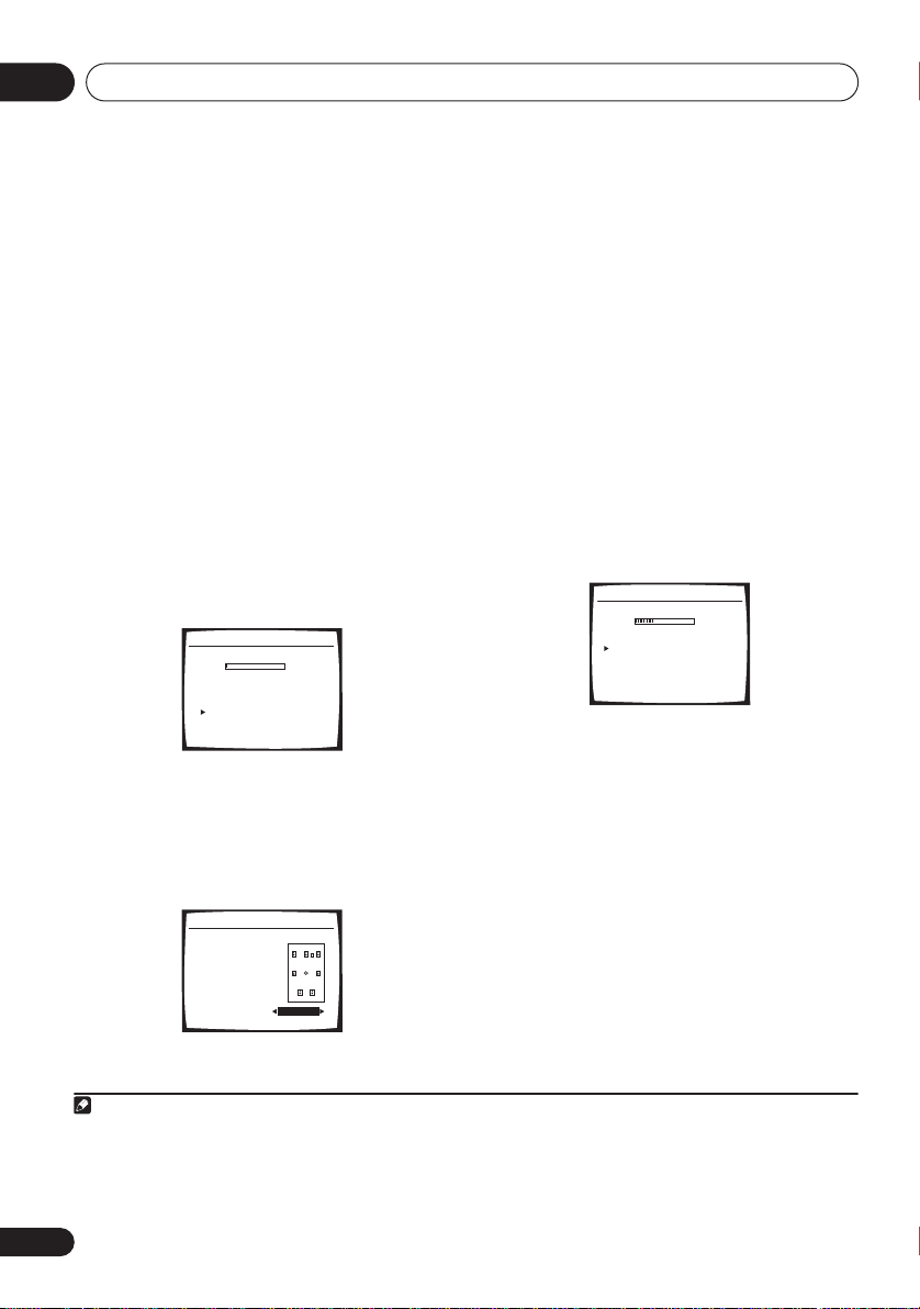
4 Select ‘Auto MCACC’ from the System
Setup menu then press ENTER.
System Setup
1.Surr Back System
2.Auto MCACC
3.Manual MCACC
4.Manual SP Setup
5.Input Assign
6.Other Setup
PUSH OPEN
tab to access
jack.
MASTER
MCACC
SETUP MIC
VOLUME
UPDOWN
on the remote control,
SETUP
button.
and
ENTER
on the remote
RETURN
to exit the
at any time to exit the System
1
2. Auto MCACC
Surr Back System
Normal (SB) ]
: Exit
: Cancel ENTER: Start
English
Deutsch
Français
Italiano
Nederlands
Español
Note
1 The screensaver automatically starts after three minutes of inactivity. If you cancel the Auto MCACC Setup at any time, the
receiver automatically exits and no settings will be made.
9
En
Quick surround sound setup03
5 Make sure ‘Normal (SB)’ is selected then
press ENTER.
1
Try to be as quiet as possible after pressing
ENTER
. The system outputs a series of test
tones to establish the ambient noise level.
6 Follow the instructions on-screen.
• Make sure the microphone is connected.
• If you’re using a subwoofer, it is
automatically detected every time you
switch on the system. Make sure it is on
and the volume is turned up.
• See below for notes regarding background
noise and other possible interference.
7 Wait for the test tones to finish.
A progress report is displayed on-screen while
the receiver outputs test tones to determine
the speakers present in your setup. Try to be as
quiet as possible while it’s doing this.
2.Auto MCACC
Now Analyzing
Environment Check
Ambient Noise [ OK ]
Microphone [ ]
Speaker YES/NO [ ]
OK
OK
:Cancel
If the speaker configuration displayed isn’t
correct, use
to change the setting (and number for
/
to select the speaker and
/
surround back). When you’re finished, go to
the next step.
If you see an error message (
ERR
) in the right
side column, there may be a problem with the
speaker connection. If selecting
RETRY
doesn’t fix the problem, turn off the power and
check the speaker connections.
9 Make sure ‘OK’ is selected, then press
ENTER.
A progress report is displayed on-screen while
the receiver outputs more test tones to
determine the optimum receiver settings for
speaker setting, channel level, speaker
distance, and Acoustic Calibration EQ.
2.Auto MCACC
Now Analyzing
Surround Analyzing
Speaker System [ ]
Speaker Distance [ ]
Channel Level [ ]
Acoustic Cal EQ [ ]
:Cancel
Again, try to be as quiet as possible while this
is happening. It may take 3 to 8 minutes.
• For correct speaker settings, do not adjust
the volume during the test tones.
8 Confirm the speaker configuration.
The configuration shown on-screen should
reflect the actual speakers you have.
2.Auto MCACC
CHECK!
Front [ YES ]
Center [ YES ]
Surround [ YES ]
SB [ Yx2 ]
SUB W. [ YES ]
OK
:Cancel
10 The Auto MCACC Setup has finished!
Select ‘SKIP’ to go back to the System Setup
menu.
The MCACC indicator on the front panel will
light to show the setup is complete.
The settings made in the Auto MCACC Setup
should give you excellent surround sound from
your system, but it is also possible to adjust
these settings manually using the System
Setup menu (starting on page 36).
2
You can also choose to view the settings by
selecting individual parameters from the
Analyzed Data Check
Note
1 If you are planning on bi-amping your front speakers, or setting up a separate speaker system in another room, read through
Surround back speaker setting
2• Depending on the characteristics of your room, sometimes identical speakers with cone sizes of around 12 cm will end up
with different size settings. You can correct the setting manually using the
• The subwoofer distance setting may be farther than the actual distance from the listening position. This setting should be
accurate (taking delay and room characteristics into account) and generally does not need to be changed.
on page 36 and make sure to connect your speakers as necessary before continuing.
Speaker Setting
screen:
on page 42.
10
En

Quick surround sound setup
•
Speaker Setting
speakers you’ve connected (see page 42
for more on this)
•
Speaker Distance
speakers from the listening position (see
page 44 for more on this)
•
Channel Level
your speaker system (see page 43 for more
on this)
•
Acoustic Cal EQ
frequency balance of your speaker system
based on the acoustic characteristics of
your room (see page 39 for more on this)
Press
RETURN
checking each screen. When you’re finished,
select
SKIP
menu.
to go back to the System Setup
Other problems when using the Auto
MCACC Setup
If the room environment is not optimal for the
Auto MCACC Setup (too much background
noise, echo off the walls, obstacles blocking
the speakers from the microphone) the final
settings may be incorrect. Check for household
appliances (air conditioner, fridge, fan, etc.),
that may be affecting the environment and
switch them off if necessary. If there are any
instructions showing in the front panel display,
please follow them.
• Some older TVs may interfere with the
operation of the microphone. If this seems
to be happening, switch off the TV when
doing the Auto MCACC Setup.
– The size and number of
– The distance of your
– The overall balance of
– Adjustments to the
after you have finished
03
English
Deutsch
Français
Italiano
Nederlands
Español
11
En
Connecting up04
S
Chapter 4:
Connecting up
Making cable connections
Important
• Before making or changing connections,
switch off the power and disconnect the
power cord from the AC outlet.
• Make sure not to bend the cables over the
top of this unit. If this happens, the
magnetic field produced by the
transformers in this unit may cause a
humming noise from the speakers.
• Before unplugging the power cord, switch
the power into standby.
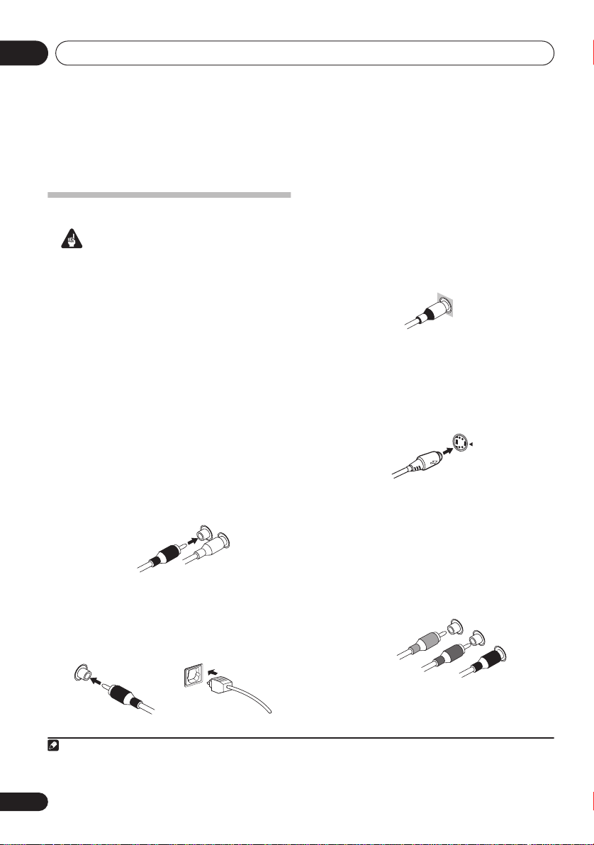
Analog audio cables
Use stereo RCA phono cables to connect
analog audio components. These cables are
typically red and white, and you should
connect the red plugs to R (right) terminals
and white plugs to L (left) terminals.
Analog audio cables
Right (red)
Left (white)
Digital audio cables
Commercially available coaxial digital audio
cables or optical cables should be used to
connect digital components to this receiver.
1
Video cables
Standard RCA video cables
These cables are the most common type of
video connection and are used to connect to
the composite video terminals. The yellow
plugs distinguish them from cables for audio.
tandard RCA video cable
S-video cables
S-video cables give you a clearer picture
reproduction than standard RCA video cables
by sending separate signals for the luminance
and color.
S Video
Component video cables
Use component video cables to get the best
possible color reproduction of your video
source. The color signal of the TV is divided into
the luminance (
PR) signals and then output. In this way,
interference between the signals is avoided.
Y
) signal and the color (
Component video cables
Green (Y)
Blue (P
B)
Red (P
PB and
R)
Coaxial digital audio cable Optical cable
Note
1• When connecting optical cables, be careful when inserting the plug not to damage the shutter protecting the optical socket.
• When storing optical cable, coil loosely. The cable may be damaged if bent around sharp corners.
• You can also use a standard RCA video cable for coaxial digital connections.
12
En
Connecting up
04
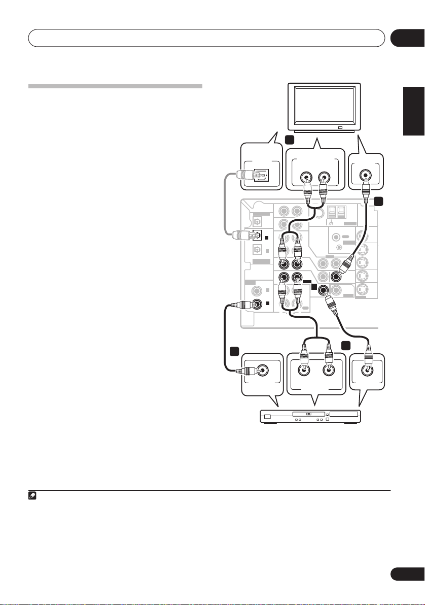
Connecting a DVD player and TV
This page shows you how to connect your DVD
player and TV to the receiver.
1 Connect a coaxial digital audio output on
your DVD player to the DIGITAL COAX 1
(DVD/LD) input on this receiver.
Use a coaxial digital audio cable for the
connection.
2 Connect the composite video output and
the stereo analog audio outputs
DVD player to the DVD/LD inputs on this
receiver.
Use a standard RCA video cable3 and a stereo
RCA phono cable for the connection.
• If your DVD player has multichannel
3 Connect the analog audio outputs from
your TV to the TV/SAT inputs on this receiver.
This will allow you to play the sound from the
TV's built-in tuner. Use a stereo RCA phono
cable to do this.
• If your TV has a built-in digital decoder, you
4 Connect the MONITOR OUT video jack on
this receiver to a video input on your TV.
Use a standard RCA video cable to connect to
the composite video jack.
1
2
on your
analog outputs, see
multichannel analog outputs
Connecting the
below for how
to connect it.
can also connect an optical digital audio
output from your TV to the
(TV/SAT)
input on this receiver. Use an
DIGITAL OPT 2
optical cable for the connection.
4
DIGITAL
AUDIO OUT
OPTICAL
DIGITAL OUT
(
TV/ SAT
(CD)
ASSIGNABLE
DIGITAL IN
ASSIGNABLE
DIGITAL IN
This receiver
1
COAXIAL
DIGITAL OUT
3
IN
OPT
IN
OPT
2
)
IN
OPT
1
OUT
IN
IN
COAX
2
(
)
DVR/VCR
IN
COAX
1
(
)
DVD/LD
OUT
R
AUDIO
DVD player
ANALOG AUDIO OUT
LR
AUX
FM UNBAL
Ω
75
CD
DVR/
VCR
IN
TV/
SAT
IN
DVD
/LD
FRONT
D V D
5.1CH
INPUT
PLAY
IN
CD-R
/TAPE
/MD
REC
L
AUDIORL
ANALOG OUT
VIDEO
LOOP
AM
TV
ANTENNA
OUT
CONTROL
IN
OUT
MONITOR
OUT
SUB
WOOFER
PREOUT
2
VIDEO IN
MONITOR OUT
S-VIDEO
VIDEO OUT
English
Deutsch
4
OUT
DVR/
VCR
IN
TV/
SAT
IN
DVD
/LD
IN
Français
Italiano
Nederlands
Español
Note
1 If your DVD player only has an optical digital output, you can connect it to the optical input on this receiver using an optical
cable. When you set up the receiver you'll need to tell the receiver which input you connected the player to (see
menu
on page 63).
2 This connection will allow you to make analog recordings from your DVD player.
3 For better quality, you can also connect with S-video using the
video output, you can connect this too. See
4 For better quality, you can also connect with S-video using the
jacks
on page 17 if you want to use the component video outputs to connect this receiver to your TV.
Using the component video jacks
S-VIDEO DVD/LD
S-VIDEO MONITOR OUT
jack. If your player also has a component
on page 17 for more on this.
jack. See
The Input Assign
Using the component video
13
En
Connecting up04
O
B
C
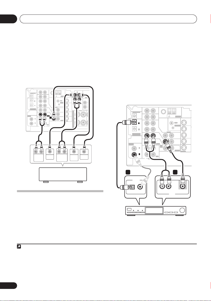
Connecting the multichannel analog
outputs
For DVD Audio and SACD playback, your DVD
player may have 5.1 channel analog outputs.In
this case, you can connect the multichannel
analog outputs to the multichannel inputs of
this receiver as shown below.
This receiver
ASSIGNABLE
DIGITAL IN
DIGITAL OUT
(
TV/ SAT
(CD)
ASSIGNABLE
DIGITAL IN
AUX
IN
OPT
OPT
2
)
OPT
1
COAX
2
(
DVR/VCR
COAX
1
(
DVD/LD
FM UNBAL
Ω
75
IN
CD
DVR/
IN
VCR
OUT
IN
IN
)
IN
)
OUT
R
RL RL
FRONT
OUTPUT
VIDEO
IN
TV/
SAT
IN
DVD
/LD
FRONT
D V D
5.1CH
INPUT
PLAY
IN
CD-R
/TAPE
/MD
REC
L
AUDIO
CENTER
OUTPUT
DVD/multi-channel decoder
with multi-channel analog
output jacks
AM
ANTENNA
LOOP
OUT
CONTROL
IN
OUT
MONITOR
OUT
SUB
WOOFER
PREOUT
SURROUND
OUTPUT
1
CENTER
MONITOR OUT
R
SURROUND
DVD 5.1CH INPUT
OUT
DVR/
VCR
IN
RL
S
TV/
SAT
P
IN
E
DVD
A
A
/LD
IN
K
S-VIDEO
E
R
S
SUB
WOOFER
OUTPUT
SUB
WOOFER
COMPONE
(
L
DVR/V
P
Y
MONIT
FRONT
R
VIDEO
OUTPUT
1 Connect a set of audio/video outputs on
the set-top box component to the TV/SAT
AUDIO and VIDEO inputs on this receiver.
2
Use a stereo RCA phono cable for the audio
connection and a standard RCA video cable for
the video connection.
3
2 Connect an optical digital audio output
from your set-top box component to the
DIGITAL OPT 2 (TV/SAT) input on this receiver.
Use an optical cable for the connection.
4
This receiver
(
TV/ SAT
ASSIGNABLE
DIGITAL IN
DIGITAL OUT
OPT
OPT
)
OPT
(CD)
ASSIGNABLE
DIGITAL IN
COAX
(
DVR/VCR
COAX
(
DVD/LD
2
1
2
1
AUX
IN
IN
CD
DVR/
IN
VCR
OUT
TV/
SAT
IN
DVD
/LD
FRONT
IN
PLAY
)
CD-R
IN
/TAPE
/MD
)
REC
OUT
R
L
AUDIO
FM UNBAL
IN
IN
D V D
5.1CH
INPUT
AM
ANTENNA
Ω
LOOP
75
IN
VIDEO
OUT
CONTROL
IN
OUT
MONITOR
OUT
SUB
WOOFER
PREOUT
MONITOR OUT
IN
S-VIDEO
OUT
DVR/
VCR
IN
TV/
SAT
IN
DVD
/LD
2 1
DIGITAL OUT
OPTICAL COAXIAL
Connecting a satellite receiver
L
AV OUT
or other digital set-top box
Satellite and cable receivers, and terrestrial
digital TV tuners are all examples of so-called
'set-top boxes'.
Note
1 The multichannel input can only be used when
2 If you've already connected your TV to the
need to press the input select button for the input you connected the set-top box to.
3 For better quality, you can also connect with S-video using the
video output, you can connect this too. See
4 If your satellite/cable receiver doesn’t have a digital audio output, omit this step. If it only has a coaxial digital output, you can
connect it to one of the coaxial inputs on this receiver using a coaxial digital audio cable. When you set up the receiver you'll
need to tell the receiver which input you connected the set-top box to (see
DVD 5.1 ch
TV/SAT
Using the component video jacks
is selected (see page 33).
inputs, simply choose another input. However, to receive a signal, you'll
S-VIDEO TV/SAT
14
En
STB
jack. If your set-top box also has a component
on page 17 for more on this.
The Input Assign menu
on page 63).
VIDEOAUDIOR
Connecting up
04
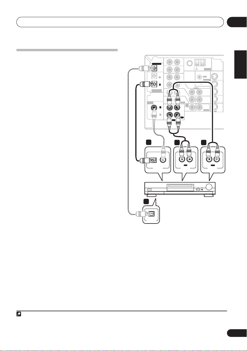
Connecting other audio
components
The number and kind of connections depends
on the kind of component you’re connecting.
Follow the steps below to connect a CD-R, MD,
DAT, tape recorder or other audio component.
1 If your component has a digital output,
connect this to a digital input on the receiver
as shown.
The example shows a coaxial connection to the
CD
digital input jack using a coaxial digital
audio cable.
2 If necessary, connect the analog audio
outputs of the component to a set of spare
audio inputs on this receiver.
You’ll need to make this connection for
components without a digital output, or if you
want to record from a digital component. Use a
stereo RCA phono cable as shown.
3 If you're connecting a recorder, connect
the analog audio outputs (REC) to the analog
audio inputs on the recorder.
The example shows an analog connection to
the
CD-R/TAPE/MD
analog output jack using
a stereo RCA phono cable.
4 If your recorder has a digital input,
connect it to the digital output on the receiver
as shown.
Use an optical cable to make this connection.
1
This receiver
4
(
TV/ SAT
ASSIGNABLE
DIGITAL IN
1
OPTICAL
DIGITAL OUT
OPT
OPT
)
OPT
(CD)
ASSIGNABLE
DIGITAL IN
COAX
(
DVR/VCR
COAX
(
DVD/LD
2
1
2
1
AUX
IN
IN
CD
DVR/
IN
VCR
OUT
TV/
SAT
IN
DVD
/LD
FRONT
IN
)
)
PLAY
CD-R
IN
/TAPE
/MD
REC
OUT
R
L
AUDIO
R
CD-R, MD, DAT,
AUDIO IN
D V D
5.1CH
INPUT
IN
REC
FM UNBAL
75
IN
IN
IN
AM
ANTENNA
Ω
LOOP
MONITOR OUT
OUT
CONTROL
IN
OUT
MONITOR
OUT
SUB
WOOFER
PREOUT
S-VIDEO
OUT
DVR/
VCR
IN
TV/
SAT
IN
DVD
/LD
IN
VIDEO
23
OUT
L
R
AUDIO OUT
L
PLAY
Tape recorder, etc.
OPTICAL
DIGITAL IN
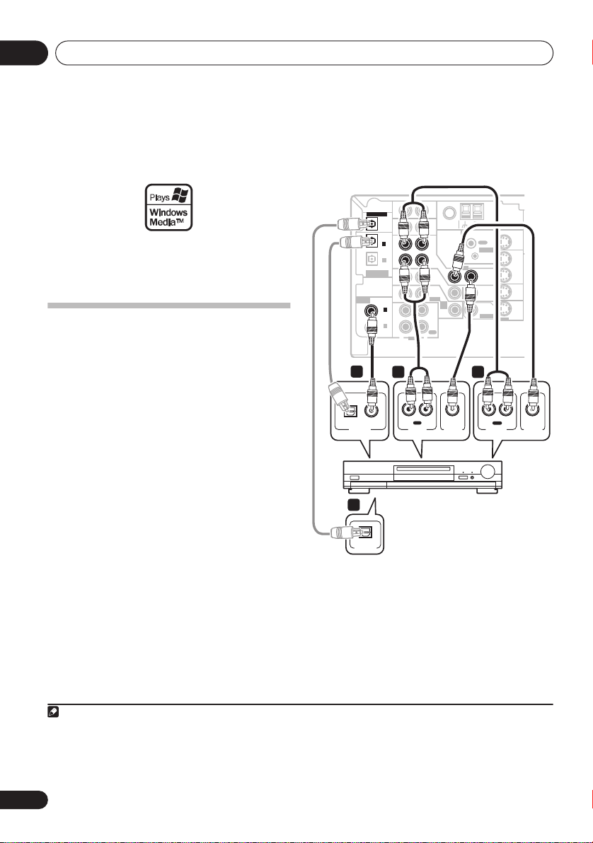
About the WMA9 Pro decoder
This unit has an on-board Windows Media®
Audio 9 Professional (WMA9 Pro) decoder, so
it is possible to playback WMA9 Pro-encoded
audio using a coaxial or optical digital
connection when connected to a WMA9 Procompatible player.
English
Deutsch
Français
Italiano
Nederlands
Español
Note
1 Note that you must connect digital components to analog audio jacks if you want to record to/from digital components (like
an MD) to/from analog components.
15
En
Connecting up04
However, the connected DVD player, set-top
box, etc. must be able to output WMA9 Pro
format audio signals through a coaxial or
optical digital output.
Microsoft, Windows Media®, and the Windows logo are
trademarks, or registered trademarks of Microsoft
Corporation in the United States and/or other countries.
Connecting other video
components
This receiver has audio/video inputs and
outputs suitable for connecting analog or
digital video recorders, including VCRs, DVDrecorders and HDD recorders.
1 Connect a set of audio/video outputs on
the recorder to the DVR/VCR AUDIO and
VIDEO inputs on this receiver.
Use a stereo RCA phono cable for the audio
connection and a standard RCA video cable for
the video connection.
2 Connect a set of audio/video inputs on
the recorder to the DVR/VCR AUDIO and
VIDEO outputs on this receiver.
Use a stereo RCA phono cable for the audio
connection and a standard RCA video cable for
the video connection.
3 Connect a coaxial digital audio output on
your video component to the DIGITAL COAX 2
(DVR/VCR) input on this receiver.
Use a coaxial digital audio cable for the
connection.
3
1
2
4 If your video component has a digital
input, connect it to the digital output on the
receiver as shown.
Use an optical cable to make this connection.
This receiver
(
TV/ SAT
ASSIGNABLE
ASSIGNABLE
DIGITAL IN
3
OPTICAL COAXIAL
DIGITAL OUT
4
OPTICAL
DIGITAL IN
DIGITAL OUT
OPT
OPT
)
(CD)
DIGITAL IN
COAX
(
DVR/VCR
COAX
(
DVD/LD
2
OPT
1
2
1
AUX
IN
IN
CD
DVR/
IN
VCR
OUT
IN
DVD
/LD
FRONT
IN
PLAY
)
CD-R
IN
/TAPE
/MD
)
REC
OUT
R
L
AUDIO
1
IN
R L
REC
AUDIO IN
AM
FM UNBAL
ANTENNA
Ω
LOOP
75
OUT
CONTROL
IN
VIDEO
IN
TV/
SAT
OUT
IN
MONITOR
OUT
D V D
5.1CH
SUB
INPUT
WOOFER
IN
PREOUT
2
R L
AUDIO OUT
VIDEO IN
VCR, DVR, LD player, etc.
MONITOR OUT
S-VIDEO
OUT
PLAY
OUT
DVR/
VCR
IN
TV/
SAT
IN
DVD
/LD
IN
VIDEO OUT
Note
1 For better quality, you can also connect with S-video using the
a component video output, you can connect this too. See
2 For better quality, you can also connect with S-video using the
3 If your video component only has an optical digital output, you can connect it to the optical input on this receiver using an
optical cable. When you set up the receiver you'll need to tell the receiver which input you connected the player to (see
Assign menu
on page 63).
S-VIDEO DVR/VCR IN
Using the component video jacks
S-VIDEO DVR/VCR OUT
jack. If your video component also has
on page 17 for more on this.
jack.
16
En
The Input
Connecting up
PROCESSING
04
Using the component video jacks
Component video should deliver superior
picture quality when compared to composite
video. A further advantage (if your source and
TV are both compatible) is progressive-scan
video, which delivers a very stable, flicker-free
picture. See the manuals that came with your
TV and source component to check whether
they are compatible with progressive-scan
video.
Important
• If you connect any source component to
the receiver using a component video
input, you must also have your TV
connected to this receiver's
VIDEO MONITOR OUT
1 Connect the component video outputs of
your source to a set of component video
inputs on this receiver.
Use a three-way component video cable for the
connection.
2 If necessary, assign the component video
inputs to the input source you've connected.
This only needs to be done if you didn’t connect
according to the following defaults:
•
COMPONENT 1
•
COMPONENT 2
•
COMPONENT 3
See
Assigning the component video inputs
–
–
–
DVD
TV
DVR
page 63 for more on this.
3 Connect the COMPONENT VIDEO
MONITOR OUT jacks on this receiver to the
component video inputs on your TV or
monitor.
Use a three-way component video cable.
COMPONENT
jacks.
on
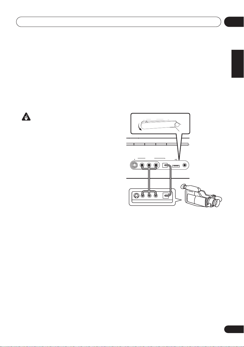
Connecting to the front panel video
terminal
Front video connections are accessed via the
front panel using the
standard audio/video jacks as well as an Svideo jack and an optical input. Hook them up
the same way you made the rear panel
connections.
• Push down on the
access the front video connections.
VIDEO
S-VIDEO
CD-R/TAPE/MD FM AM
CD
VIDEO
VIDEO OUTPUT
INPUT
LV
S-VIDEO
This receiver
INPUT
R
USB
DIGITAL INAUDIO RLVIDEO
DIGITAL INAUDIO RLVIDEO
DIGITAL OUT
VIDEO
button. There are
PUSH OPEN
MCACC
SETUP MIC
PUSH
OPEN
USB
AUX
MCACC
USB
SETUP MIC
tab to
Video
camera
(etc.)
English
Deutsch
Français
Italiano
Nederlands
Español
17
En
Connecting up04
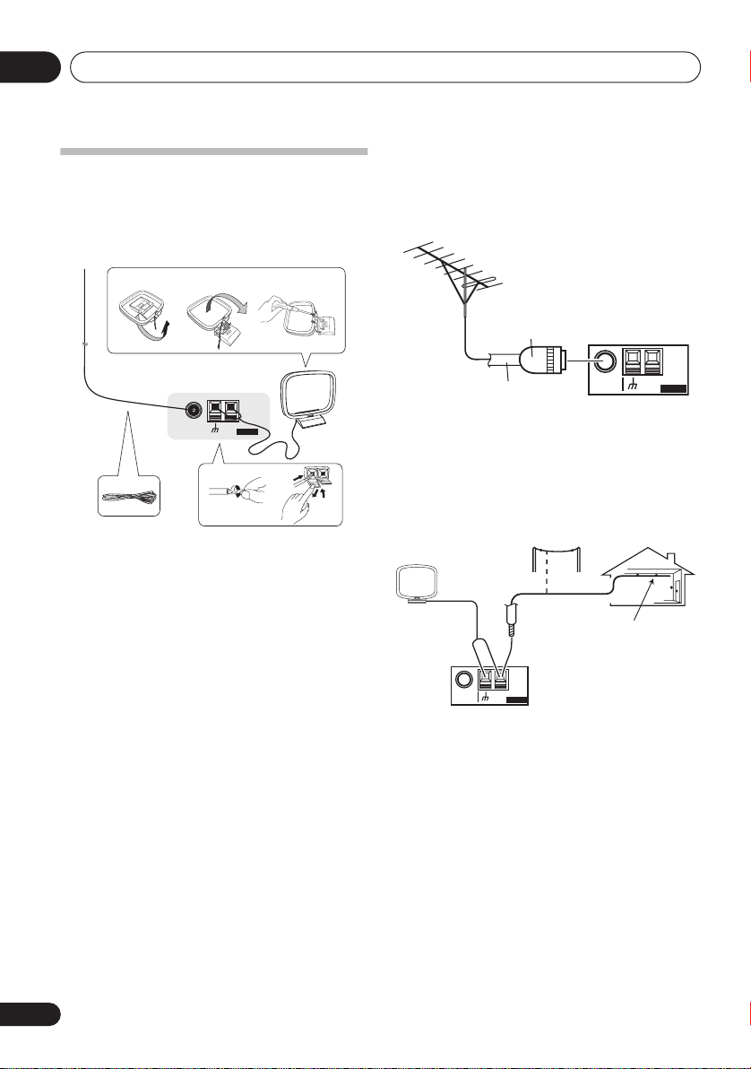
Connecting antennas
Connect the AM loop antenna and the FM wire
antenna as shown below. To improve reception
and sound quality, connect external antennas
(see
Using external antennas
fig. a fig. b fig. c
below).
Using external antennas
To improve FM reception
Use a PAL connector to connect an external
FM antenna.
One-touch
PAL connector
3
5
FM UNBAL
75
AM
Ω
LOOP
ANTENNA
1
4
2
1 Pull off the protective shields of both AM
antenna wires.
2 Push open the tabs, then insert one wire
fully into each terminal, then release the tabs
to secure the AM antenna wires.
3 Fix the AM loop antenna to the attached
stand.
To fix the stand to the antenna, bend in the
direction indicated by the arrow (
clip the loop onto the stand (
fig. b
fig. a
).
) then
• If you plan to mount the AM antenna to a
wall or other surface, secure the stand with
screws (
fig. c
) before clipping the loop to
the stand. Make sure the reception is clear.
4 Place the AM antenna on a flat surface
and in a direction giving the best reception.
5 Connect the FM wire antenna in the same
way as the AM loop antenna.
For best results, extend the FM antenna fully
and fix to a wall or door frame. Don’t drape
loosely or leave coiled up.
FM UNBAL
AM
75
Ω
LOOP
75 Ω coaxial cable
ANTENNA
To improve AM reception
Connect a 5 to 6 meter length of vinyl-coated
wire to the AM antenna terminal without
disconnecting the supplied AM loop antenna.
For the best possible reception, suspend
horizontally outdoors.
Outdoor
antenna
5 to 6 meters
Indoor antenna
(vinyl-coated wire)
FM UNBAL
AM
Ω
75
LOOP
ANTENNA
18
En
Connecting up
04
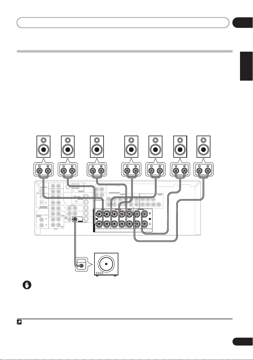
Connecting the speakers
A complete setup of eight speakers (including the subwoofer) is shown here but everyone’s home
setup will vary. Simply connect the speakers you have in the manner shown below.
will work with just two stereo speakers (the front speakers in the diagram) but using at least three
speakers is recommended, and a complete setup is best.
Make sure you connect the speaker on the right to the right terminal and the speaker on the left
to the left terminal. Also make sure the positive and negative (
2
those on the speakers.
(please see
Switching the speaker impedance
impedance of less than 8
Front speakers
LR C LSRS
DIGITAL OUT
IN
OPT
IN
OPT
2
(
)
TV/ SAT
IN
OPT
1
OUT
(CD)
ASSIGNABLE
DIGITAL IN
IN
ASSIGNABLE
IN
DIGITAL IN
COAX
2
(
)
DVR/VCR
IN
COAX
1
(
)
DVD/LD
OUT
R
This receiver
You can use speakers with a nominal impedance between 6 Ω to 16 Ω
on page 68 if you plan to use speakers with an
Ω
).
Center speaker
SUB
CEN-
WOOFER
AUX
AM
FM UNBAL
ANTENNA
Ω
LOOP
75
CD
OUT
CONTROL
DVR/
VCR
VIDEO
IN
TV/
OUT
SAT
IN
DVD
MONITOR
/LD
OUT
FRONT
D V D
5.1CH
SUB
INPUT
PLAY
WOOFER
IN
CD-R
PREOUT
/TAPE
/MD
REC
L
AUDIO
TER
MONITOR OUT
IN
S-VIDEO
L
R
SURROUND
DVD 5.1CH INPUT
OUT
DVR/
VCR
FRONT
IN
RL
S
TV/
SAT
P
IN
E
DVD
A
A B
/LD
IN
K
E
R
S
Surround speakers
COMPONENT VIDEO
ASSIGNABLE
3
(
)
IN
DVR/VCR
P
B
PR
Y
Y
MONITOR OUT
L
R
(
)
IN
DVD/LD
B
P
(
)
2
IN
TV/SAT
CENTERSURROUND
R
Powered
1
PR
SURROUND BACK
+/–
FRONT SURROUND SURROUND
L
LL
RRR
L
) terminals on the receiver match
Surround back speakers
SBL SBR
PREOUT
BACK
CENTER
subwoofer
SW
INPUT
1
The receiver
English
Deutsch
Français
Italiano
Nederlands
Español
Caution
• Make sure that all the bare speaker wire is twisted together and inserted fully into the speaker
terminal. Use good quality speaker wire to connect the speakers to the receiver.
Note
1 If you’re not using a subwoofer, change the front speaker setting (see
2 If you are using only one surround back speaker, connect it to the surround back left (
Speaker Setting
on page 42) to
L
) terminal.
LARGE
.
19
En
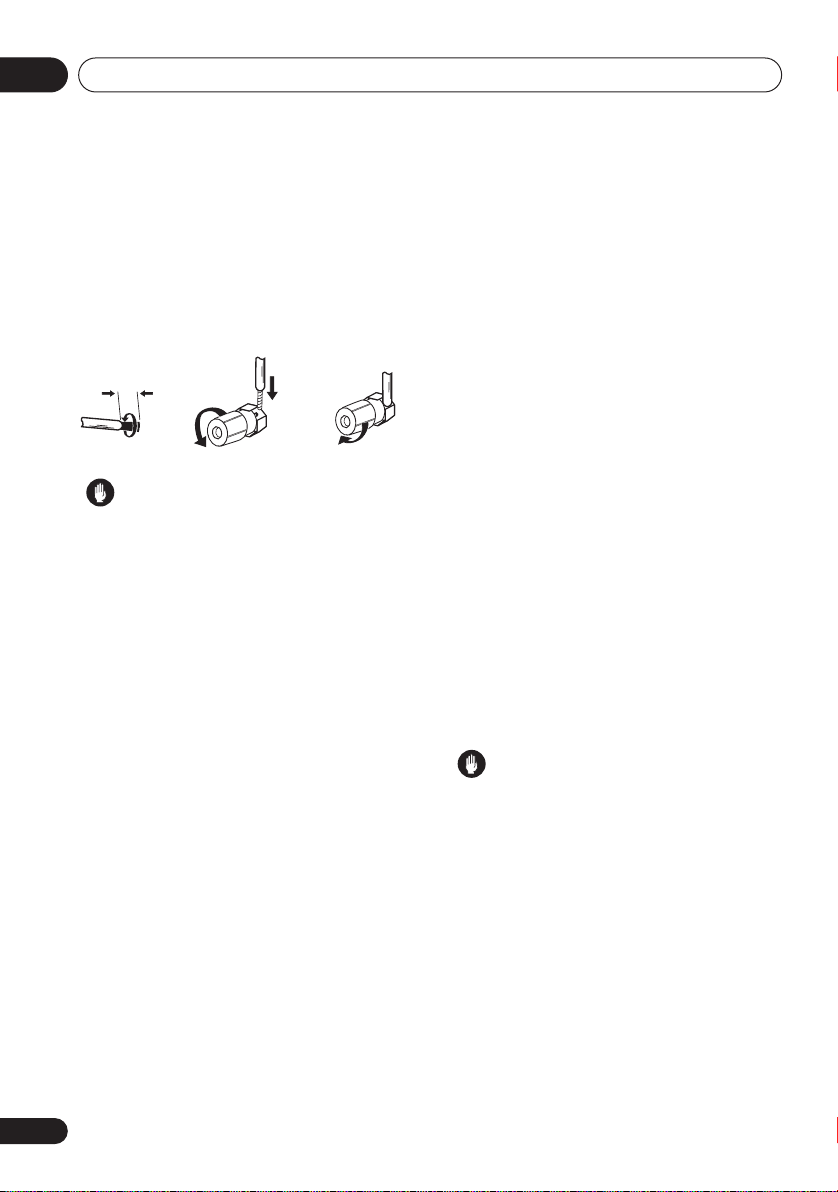
Connecting up04
Make sure that the speaker cable you’re using
is properly prepared with about 10 mm of
insulator stripped from each wire, with the
exposed wire strands twisted together (
Unscrew the terminal a few turns until there is
enough space to insert the exposed wire
(
fig. B
). Once the wire is in position, tighten the
terminal until the wire is firmly clamped (
fig. A fig. B fig. C
10 mm
Caution
• These speaker terminals carry
HAZARDOUS LIVE voltage
the risk of electric shock when connecting
or disconnecting the speaker cables,
disconnect the power cord before touching
any uninsulated parts.
fig. A
fig. C
. To prevent
Hints on speaker placement
Speakers are usually designed with a
particular placement in mind. Some are
designed to be floorstanding, while others
should be placed on stands to sound their best.
Some should be placed near a wall; others
should be placed away from walls. We have
provided a few tips on getting the best sound
from your speakers (following), but you should
also follow the guidelines on placement that
the speaker manufacturer provided with your
particular speakers to get the most out of
them.
• Place the front left and right speakers at
equal distances from the TV.
• When placing speakers near the TV, we
recommend using magnetically shielded
speakers to prevent possible interference,
such as discoloration of the picture when
the TV is switched on. If you do not have
magnetically shielded speakers and notice
discoloration of the TV picture, move the
).
).
speakers farther away from the TV.
• If you're using a center speaker, place the
front speakers at a wider angle. If not, place
them at a narrower angle.
• Place the center speaker above or below
the TV so that the sound of the center
channel is localized at the TV screen. Also,
make sure the center speaker does not
cross the line formed by the leading edge
of the front left and right speakers.
• It is best to angle the speakers towards the
listening position. The angle depends on
the size of the room. Use less of an angle
for bigger rooms.
• Surround and surround back speakers
should be positioned 60 cm to 90 cm
higher than your ears and titled slightly
downward. Make sure the speakers don't
face each other.
• To achieve the best possible surround
sound, install your speakers as shown
below. Be sure all speakers are installed
securely to prevent accidents and improve
sound quality.
Caution
• If you choose to install the center speaker
on top of the TV, be sure to secure it with
putty, or by other suitable means, to reduce
the risk of damage or injury resulting from
the speaker falling from the TV in the event
of external shocks such as earthquakes.
• Make sure no exposed speaker wire is
touching the rear panel, this may cause the
receiver to turn off automatically.
20
En
Connecting up
04
Overhead view of speaker setup
You can also refer to the 3-D speaker setup
illustration on page 7.
Front
left
Surround
left
Listening position
Surround back Surround back
left right
Single surround back speaker
Front
rightCenter
Subwoofer
Surround
right
.
The diagrams below show suggested surround
and surround back speaker orientation. The
first diagram (
fig. A
) shows orientation with one
surround back speaker (or none) connected.
The second (
fig. B
) shows orientation with two
surround back speakers connected.
90 to 120
SBR
RS
SBR
LS
LS
fig. A
LS
RS
0 to 60
RS
SBL
SB
SBL
fig. B
English
Deutsch
Français
Italiano
Nederlands
Español
3-D view of
7.1 channel
speaker setup
21
En
Controls and displays05
DIGITAL PRECISION
PROCESSING
Chapter 5:
Controls and displays
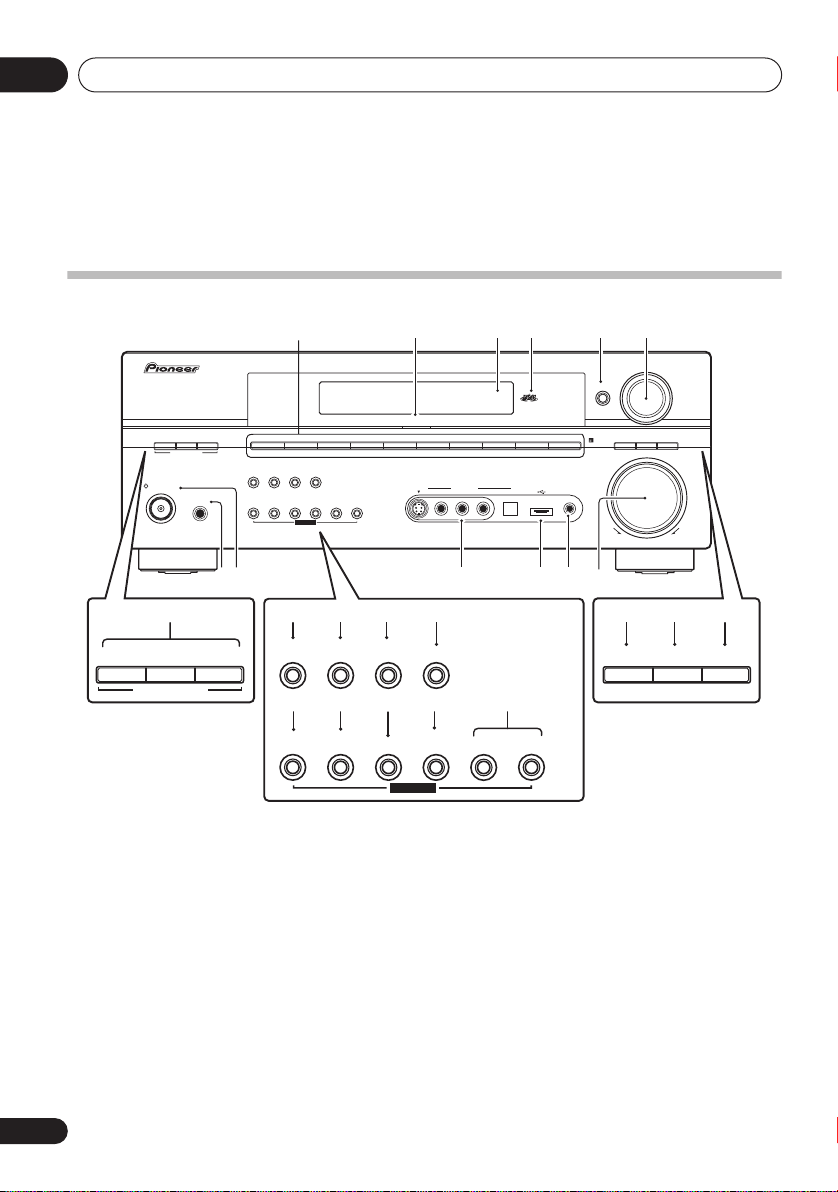
Front panel
32 4
AUDIO/VIDEO MULTI-CHANNEL RECEIVER
AM
USB
AUX
INPUT
VIDEO
MCACC
USB
SETUP MICDIGITAL INAUDIO RLVIDEO
STANDARD
STANDBY/ON
ADVANCED
SURR
LISTENING MODE
PHONES
ST/DIRECT/
AUTO SURR
EON
MODE
TUNING/
STATION
DVD/LD
PTY
MIDNIGHT/
SEARCH
LOUDNESS
TUNER
EDIT
1
TV/SAT DVR/ VCR VIDEO
SPEAKERS
QUICK
SETUP
TONE
SETUP
MULTI JOG
DIGITAL PRECISION
PROCESSING
CD-R/TAPE/MD FM
CD
RETURN
S-VIDEO
5 6
ENTER
SIGNAL
SELECT
PROCESSING
VSX-916
MULTI JOG
SB
ch
ACOUSTIC
EQ
MASTER
VOLUME
UPDOWN
89
7
STANDARD
ADVANCED
SURR
LISTENING MODE
ST/DIRECT/
AUTO SURR
EON
MODE
TUNING/
STATION
1 Input select buttons
Press to select an input source.
2 Digital Precision Processing indicator
Lights to indicate digital processing.
3 Character display
See
Display
on page 23.
4 MCACC indicator
Lights when Acoustic Calibration EQ (page 30)
is on (Acoustic Calibration EQ is automatically
set to
ALL CH ADJUST
after the Auto MCACC
Setup (page 9) or EQ Auto Setup (page 39)).
5
ENTER
22
En
SEARCH
TUNER
EDIT
131210 11
16 17 23 24 2514 15
MIDNIGHT/
PTY
LOUDNESS
SPEAKERS
SIGNAL
SELECT
SB ch
PROCESSING
ACOUSTIC
EQ
2118 19 20 22
QUICK
SETUP
TONE
SETUP
MULTI JOG
6
Use the
RETURN
MULTI JOG
MULTI JOG
dial
dial to select various
settings and menu options.
7
LISTENING MODE
STANDARD
buttons
– Press for Standard decoding
and to switch between the various Pro
Logic IIx and Neo:6 options (page 28).
ADVANCED SURR
– Use to switch
between the surround modes (page 29).
ST/DIRECT/AUTO SURR
Selects stereo/direct playback (page 30).
Also selects Auto Surround (
Auto playback
on page 28).
Controls and displays
8
PHONES
Use to connect headphones (when connected,
there is no sound output from the speakers).
9
Switches the receiver between on and standby.
10
VIDEO INPUT
See
Connecting to the front panel video terminal
on page 17.
11
USB
Connect a USB audio device for playback (see
Using the USB interface
12 MCACC SETUP MIC jack
Use to connect the supplied microphone.
13
MASTER VOLUME
14
EON MODE
Use to search for programs that are
broadcasting traffic or news information
(page 48).
15 PTY SEARCH
Use this button to search for RDS program
types (page 47).
16
MIDNIGHT/LOUDNESS
Switches between Midnight and Loudness
listening (page 32).
17
SPEAKERS
Use to change the speaker system (page 59)
and the impedance setting (page 68).
jack
STANDBY/ON
interface
on page 34).
dial
18
TUNING / STATION
Selects the frequency (page 45) and station
presets (page 46) when using the tuner.
19
TUNER EDIT
Press to memorize and name a station for
recall
(page 46).
20
TONE
Press this button to access the bass and treble
controls, which you can then adjust with the
MULTI JOG
21
See
dial (page 32).
QUICK SETUP
Using the Quick Setup
on page 8.
22 System Setup menu controls
SETUP
– Use with the
MULTI JOG
access the System Setup menu (page 9,
page 36, page 63).
RETURN
– Press to confirm and exit the
current menu.
23 SIGNAL SELECT
Use to select an input signal (page 33).
24
SBch PROCESSING
Selects surround back channel processing or
the virtual surround back mode (page 31).
25 ACOUSTIC EQ
Press to select an Acoustic Calibration EQ
setting (page 30).
05
English
Deutsch
Français
dial to
Italiano
Nederlands
Español
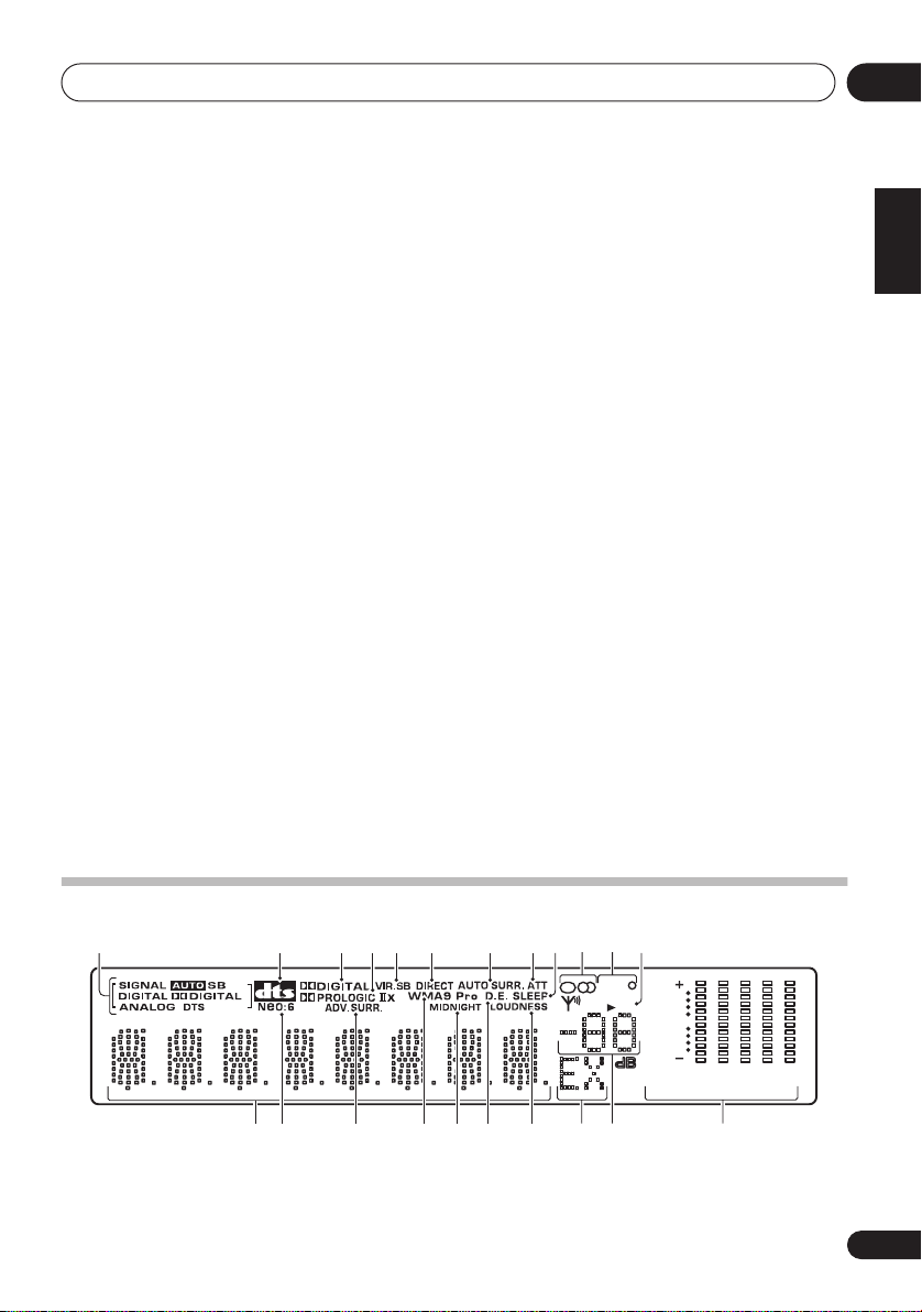
Display
1234567118910
13
14 15 20 21 22
1
SIGNAL
indicators
Lights to indicate the type of input signal:
1716 18 19
AUTO
on.
12
[]
EON
[]
C
RDS
[]
R
SP
AB
[]
Rs
[ ]
SB
[]
SB
[]
Ls
– Lights when
L
R
L
6
0
6
40
125
AUTO
signal select is
250 4K
13K
23
En
Controls and displays05
SB
– Depending on the source, this lights
when a signal with surround back channel
encoding is detected.
DIGITAL
signal is detected.
2
encoded signal is detected.
ANALOG
detected.
DTS
encoded audio signals is detected.
2
When the
to indicate decoding of a DTS multichannel
signal.
3
2
When the
to indicate decoding of a Dolby Digital
multichannel signal.
4
2
When the (
on,
2
Logic II decoding.
indicate Pro Logic IIx decoding (see
in surround sound
5 VIR.SB
Lights during Virtual surround back
processing (page 31).
6
DIRECT
Lights when source direct playback is in use.
Direct playback bypasses the tone controls for
the most accurate reproduction of a source.
7 AUTO SURR.
Lights when Auto Surround (see
on page 28) is on.
8
ATT
Lights when
attenuate (reduce) the level of the analog input
signal.
9 SLEEP
Lights when the sleep mode is active (see
Remote control
– Lights when a digital audio
DIGITAL
– Lights when a source with DTS
DIGITAL
PRO LOGIC II
PRO LOGIC II
– Lights when a Dolby Digital
– Lights when an analog signal is
STANDARD
STANDARD
STANDARD
ANALOG ATT
mode is on, this lights
mode is on, this lights
x
) Pro Logic II mode is
lights to indicate Pro
2
PRO LOGIC IIx lights to
on page 28).
is used to
below).
Listening
Auto playback
10
Tuner
indicators
–
Lights when the mono mode is set
MPX
using the
–
Lights when a stereo FM broadcast is
being received in auto stereo mode.
–
Lights when a broadcast is being
received.
11 EON/RDS indicators
EON
– Lights when the EON mode is set,
and flashes during an EON broadcast. The
indicator lights when the current station
carries the EON service (page 48).
RDS
– Lights when an RDS broadcast is
received (page 47).
12 Speaker indicators
Lights to indicate the current speaker system,
A
and/or B (page 59).
13 Character display
Neo:6
14
When the (
lights to indicate Neo:6 processing.
15
ADV.SURR
Lights when one of the Advanced Surround
modes has been selected.
16 WMA9 Pro
Lights to indicate decoding of a WMA9 Pro
signal.
17
MIDNIGHT
Lights during Midnight listening (page 32).
18 D.E.
Lights when Dialog Enhancement (DIALOG E)
is switched on (page 32).
19
LOUDNESS
Lights during Loudness listening (page 32).
20 EX
Lights when a Dolby Digital Surround EX
encoded signal is detected.
button.
STANDARD
) Neo:6 mode is on, this
. (Advanced Surround)
24
En
Controls and displays
05
21 Master volume level
22 MCACC channel EQ indicators
These indicators show the EQ balance for each
channel in
EQ settings
Checking your Acoustic Calibration
on page 41. Also, L and R light
when the Sound Retriever is active (page 32).
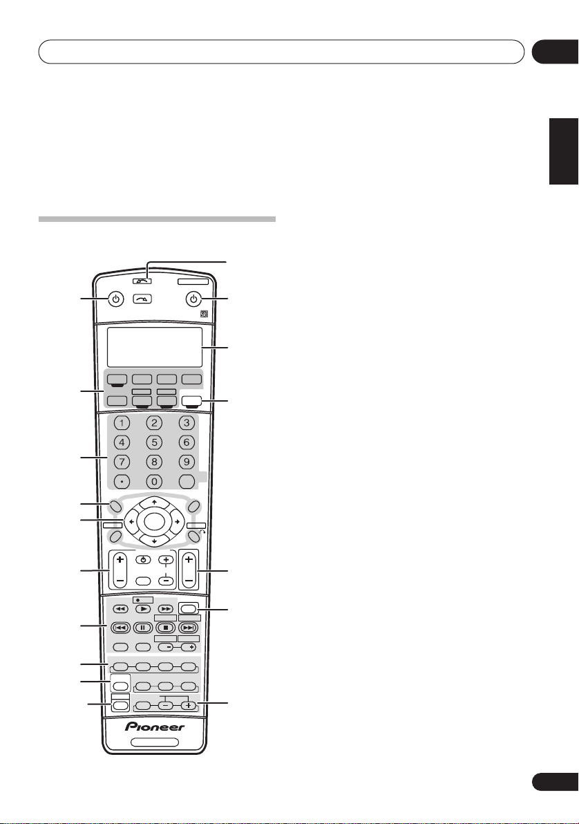
Remote control
11
RECEIVER
1
AV PRE-PROGRAMMED AND LEARNING
REMOTE CONTROL UNIT
2
3
TOP MENU
4
5
GUIDE
6
7
8
9
10
INPUT
SELECT
DVD
CD-R/TAPE
CD
SLEEP
SR+
DIALOG E
D.ACCESS
+10
ST ST
SETUP
PTY SEARCH
TV CONTROL
INPUT
TV VOL
SELECT
A
MPX
B
AUDIO
SUBTITLE
DISP
STANDARD ADV.SURR
MULTI OPE
S.RETRIEVER
EFFECT/CH SEL
SHIFT
SYSTEM OFF
TV DVR
USB
AMFM
SB ch
DIMMER
CLASS
ENTER
TUNE
ENTER
TUNE
TV CH
REC
EON
REC STOP JUKEBOX
CDE
HDD
CH
AUTO SURR
STEREO
ACOUSTIC EQ
RECEIVER
SOURCE
TV CTRL
RECEIVER
ANALOG
MIDNIGHT/
LOUDNESS
DISC
MENU
T.EDIT
RETURN
VOL
MUTE
DVD
CH
SIGNAL SEL
12
13
14
ATT
15
16
17
1 RECEIVER
This switches between standby and on for this
receiver.
2 MULTI CONTROL buttons
Press to select control of other components
(see
Controlling the rest of your system
on
page 50).
3 Number buttons and other receiver/
component controls
Use the number buttons to directly select a
radio frequency (page 45) or the tracks on a
CD, DVD, etc.
DISC (ENTER)
can be used to enter commands
for TVs, and can also be used to select a disc in
a multi-CD player.
The following are accessed by pressing the
RECEIVER
button first:
SLEEP
– Press to change the amount of
time before the receiver switches into
standby (
30 min – 60 min – 90 min – Off
You can check the remaining sleep time at
any time by pressing
SB ch
– Selects the surround back channel
SLEEP
once.
mode (page 31) or virtual surround back
mode (page 31).
ANALOG ATT
– Attenuates (lowers) the
level of an analog input signal to prevent
distortion.
SR +
– Switches the SR+ mode on/off
(page 62).
DIMMER
MIDNIGHT/LOUDNESS
– Dims or brightens the display.
– Use Midnight
when listening to movie soundtracks at low
volume. Use Loudness to boost the bass
and treble at low volume (page 32).
DIALOG E
– Use to make dialog stand out
when watching TV or a movie (page 32).
D.ACCESS
– After pressing, you can
access a radio station directly using the
number buttons (page 45).
CLASS
– Switches between the three banks
(classes) of radio station presets (page 46).
English
Deutsch
Français
Italiano
).
Nederlands
Español
25
En

Controls and displays05
4 Tuner/component control buttons/
The following button controls (except
can be accessed after you have selected the
corresponding
(
DVD, AM, FM, TV
TOP MENU
of a DVD.
MENU
Video discs. It also displays TV menus.
T.EDIT
station for recall (page 46).
SETUP
Use to access the System Setup menu (see
page 36).
GUIDE
TV.
PTY SEARCH
for RDS program types (page 47).
RETURN
current menu (also use to return to the
previous menu with DVDs).
5
Use the arrow buttons when setting up your
surround sound system (see page 36). Also
used to control DVD menus/options and for
deck 1 of a double cassette deck player. Use
the
TUNE / buttons to find radio
frequencies and use
stations (page 46).
6 TV CONTROL buttons
These buttons are dedicated to control the TV
assigned to the
only have one TV to hook up to this system
assign it to the
button. If you have two TVs, assign the main TV
to the
TV CTRL
this).
TV – Use to turn on/off the TV power.
TV VOL +/–
INPUT SELECT
signal.
TV CH +/–
MULTI CONTROL
, etc.)
– Displays the disc ‘top’ menu
– Displays the disc menu of DVD-
– Press to memorize and name a
(Press
RECEIVER
– Displays the guides on a digital
– Use this button to search
– Press to confirm and exit the
(TUNE/ST +/–) /
TV CTRL
TV CTRL MULTI CONTROL
button (see page 50 for more on
– Use to adjust the TV volume.
– Use to select the TV input
– Use to select channels.
first to access)
ENTER
ST / to find preset
button. Thus if you
SETUP
SETUP
button
7 Component control buttons
)
The main buttons (, , etc.) are used to
control a component after you have selected it
using the
The controls above these buttons can be
accessed after you have selected the
corresponding
example
The following DVR controls can be accessed by
pressing SHIFT:
8 RECEIVER CONTROL buttons
MULTI CONTROL
MULTI CONTROL
DVD
or
DVR
MPX
– Switches between stereo and mono
reception of FM broadcasts. If the signal is
weak then switching to mono will improve
the sound quality (page 45).
EON
– Use to search for programs that are
broadcasting traffic or news information
(page 48).
AUDIO
– Changes the audio language or
channel on DVD discs.
DISP
– Switches between named station
presets and radio frequencies (page 46). It
also displays RDS information (page 47).
SUBTITLE
included in multilingual DVD-Video discs.
CH +/– – Use to select channels when
using a TV, VCR, DVR, etc.
REC – Starts recording.
REC STOP – Stops recording.
JUKEBOX – Switches to the Jukebox
feature.
HDD/DVD – These buttons switch between
the hard disk and DVD controls for DVD/
HDD recorders.
STANDARD – Press for Standard decoding
and to switch between the various Pro
Logic IIx and Neo:6 options (page 28).
ADV.SURR – Use to switch between the
various surround modes (page 29).
STEREO – Selects stereo/direct playback
(page 30). Also selects the Auto Surround
mode (Auto playback on page 28).
– Displays/changes the subtitles
buttons.
).
button (for
26
En
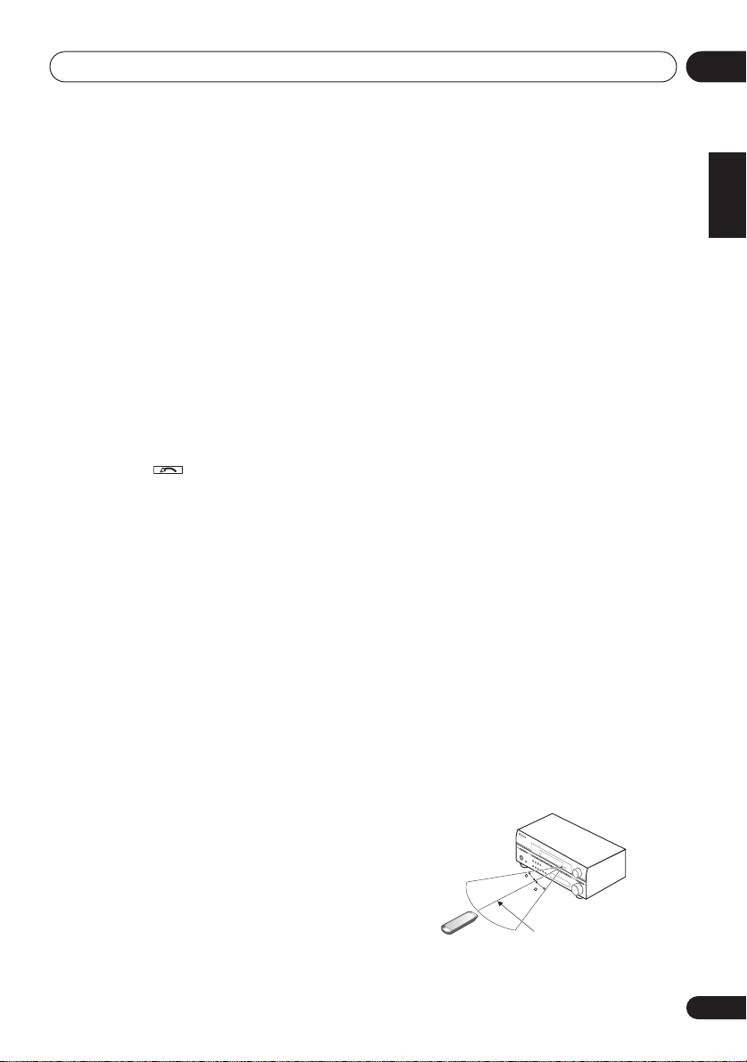
Controls and displays
05
AUTO SURR
(
Auto playback
S. RETRIEVER
– Selects Auto Surround
on page 28).
–
Press to restore CD quality
sound to compressed audio sources (page 32).
ACOUSTIC EQ
– Press to select an
Acoustic Calibration EQ setting (page 30).
SIGNAL SEL
– Use to select an input signal
(page 33).
9
MULTI OPE
Press to perform multi operations (page 53).
10
SHIFT
Press to access the DVR controls (above the
component control buttons) as well as some
receiver controls.
11 INPUT SELECT
Use to select the input source (use
INPUT SELECT
).
SHIFT
for
12SOURCE
Press to turn on/off other components
connected to the receiver (see page 50 for
more on this). Press after
MULTI OPE
to trigger
System Off (page 53).
13 Character display (LCD)
This display shows information when
transmitting control signals.
The following commands are shown when
you’re setting the remote to control other
components (see
system
on page 50):
SETUP
Controlling the rest of your
– Indicates the setup mode, from
which you choose the options below.
PRESET
– See
directly
LEARNING
from other remote controls
MULTI OP
System Off
SYS OFF
Off
on page 53.
DIRECT F
ERASE
other remote controls
Selecting preset codes
on page 51.
–
See
Programming signals
– See
Multi Operation and
on page 53.
– See
Multi Operation and System
– See
Direct function
– See
Programming signals from
on page 51.
on page 51.
on page 53.
RESET
– See
control presets
READ ID
Erasing all of the remote
on page 53.
– See
Confirming preset codes
on
page 53.
14 RECEIVER
Switches the remote to control the receiver
(used to select the green commands above the
number buttons (
DIMMER
, etc). Also use this
button to set up surround sound (page 9,
page 36).
15 VOL +/–
Use to set the listening volume.
16 MUTE
Mutes the sound or restores the sound if it has
been muted (adjusting the volume also
restores the sound).
17 EFFECT/CH SEL
Press repeatedly to select a channel, then use
+/–
to adjust the level (see
Tip
on page 44). Also
adjusts the level of the Advanced Surround
effects, Dolby Pro Logic IIx Music, and Neo:6
Music parameters (page 29). You can then use
the
+/–
buttons to make these adjustments.
Operating range of remote control
The remote control may not work properly if:
• There are obstacles between the remote
control and the receiver's remote sensor.
• Direct sunlight or fluorescent light is
shining onto the remote sensor.
• The receiver is located near a device that is
emitting infrared rays.
• The receiver is operated simultaneously
with another infrared remote control unit.
30
D
O
W
N
D
O
W
30
N
7 m
English
Deutsch
Français
Italiano
Nederlands
Español
27
En
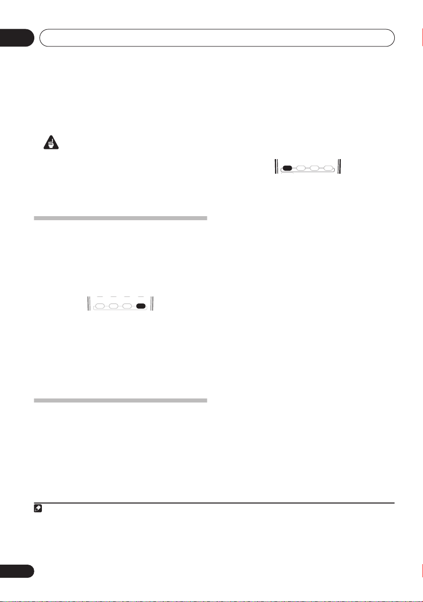
Listening to your system06
Chapter 6:
Listening to your system
Important
• Certain features explained in this section
will not be possible depending on the
source (for example, PCM 88.2 kHz / 96
kHz, DTS 96 kHz (24 bit) or WMA 9 Pro
sources).
The following modes provide basic surround
sound for stereo and multichannel sources.
AUTO SURR
STEREO
STANDARD ADV.SURR
• While listening to a source, press
STANDARD.
If necessary, press repeatedly to select a
listening mode.
Auto playback
The simplest, most direct listening option is the
Auto Surround feature. With this, the receiver
automatically detects what kind of source
you’re playing and selects multichannel or
stereo playback as necessary.
STANDARD ADV.SURR
• While listening to a source, press AUTO
SURR for auto playback of a source.
AUTOSURR. shows briefly in the display (it will
then show the decoding or playback format).
Check the digital format indicators in the
display to see how the source is being
processed.
STEREO
1
AUTO SURR
• If the source is Dolby Digital, DTS, or Dolby
Surround encoded, the proper decoding
format will automatically be selected and
shows in the display.
With two channel sources, you can select from:
• 2 Pro Logic IIx MOVIE – Up to 7.1
channel sound, especially suited to movie
sources
• 2 Pro Logic IIx MUSIC – Up to 7.1
channel sound, especially suited to music
sources
• 2 Pro Logic IIx GAME – Up to 7.1
channel sound, especially suited for video
games
• 2 PRO LOGIC – 5.1 channel surround
sound (sound from the surround speakers
is mono)
Listening in surround sound
Using this receiver, you can listen to any
source in surround sound. However, the
options available will depend on your speaker
setup and the type of source you’re listening to.
If you connected surround back speakers, see
also Using surround back channel processing
on page 31.
Note
1• Stereo surround (matrix) formats are decoded accordingly using Neo:6 CINEMA or 2 Pro Logic IIx MOVIE (see Listening
in surround sound above for more on these decoding formats).
• The Auto Surround feature is canceled if you connect headphones or select the multichannel analog inputs.
2 If surround back processing (page 31) is switched to OFF, or the surround back speakers are set to NO (page 42) (this happens
automatically if the Surround back speaker setting on page 36 is set to anything but Normal (SB)), 2 Pro Logic IIx becomes 2
Pro Logic II (5.1 channel sound).
2
• Neo:6 CINEMA – 6.1 channel sound,
especially suited to movie sources
• Neo:6 MUSIC – 6.1 channel sound,
especially suited to music sources
With multichannel sources, if you have
connected surround back speaker(s) and have
selected SB ON, you can select (according to
format):
28
En
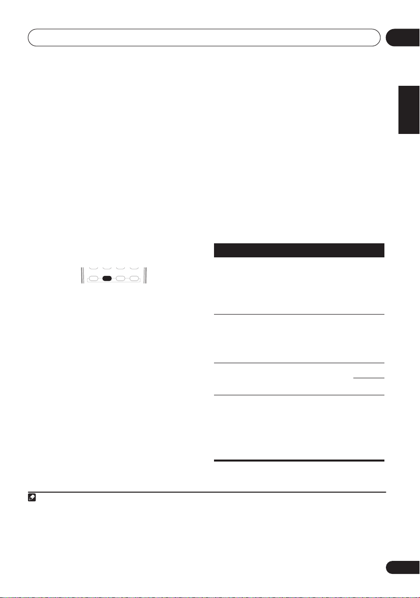
Listening to your system
CH CH
•2
Pro Logic IIx MOVIE
2 Pro Logic IIx MUSIC
•
•
Dolby Digital EX
channel sound for 5.1 channel sources and
provides pure decoding for 6.1 channel
sources (like Dolby Digital Surround EX)
•
DTS-ES
– Allows you to hear 6.1 channel
playback with DTS encoded sources
Using the Advanced surround effects
The Advanced surround effects can be used for
a variety of additional surround sound effects.
Most Advanced Surround modes are designed
to be used with film soundtracks, but some
modes are also suited for music sources. Try
different settings with various soundtracks to
see which you like.
• Press ‘
ADV.SURR
listening mode.
•
ADV. MOVIE
ADV. MUSIC
•
•
TV SURR.
both mono and stereo TV sources.
•
SPORTS
•
ADV. GAME
EXPANDED
•
surround sound for two-channel sources.
•
7-STEREO – Gives multichannel sound to a
stereo source, using all of your speakers.
•
VIR. SURR
just the subwoofer and front speakers.
•
PHONESUR.
surround with headphones.
1
STANDARD ADV.SURR
– Suitable for movie sources.
– Suitable for music sources.
– Provides surround sound for
– Suitable for sports programs.
– Suitable for video games.
– Simulates multichannel
– A virtual surround effect using
– Creates the effect of overall
– See above
– See above
– Creates surround back
AUTO SURR
STEREO
’ repeatedly to select a
2
Setting the effect options
When using surround effects, there are a
number of settings you can adjust.
1 Press
the setting you want to adjust.
Depending on the current status / mode of the
receiver, certain options may not appear.
Check the table below for notes on this.
2
See the table below for the options available for
each setting. The defaults, if not stated, are
listed in bold.
3
other settings
Setting
Center
Width
(Applicable
only when
using a center speaker)
Dimension
Panorama
Center
Image
(Applicable
only when
using a center speaker)
EFFECT/CH SEL
Use the +/– buttons
repeatedly to select
to set it as necessary.
Press EFFECT/CH SEL again to adjust
.
What it does
Spreads the center channel
a
between the front right and left
speakers, making it sound
wider (higher settings) or
narrower (lower settings).
a
Adjusts the surround sound
balance from front to back,
making the sound more distant
(minus settings), or more
forward (positive settings).
a
Extends the front stereo image
to include surround speakers
for a ‘wraparound’ effect.
Adjusts the center image to
b
create a wider stereo effect with
vocals. Adjust the effect from 0
(all center channel sent to front
right and left speakers) to 10
(center channel sent to the
center speaker only).
Options
0 to 7
Default:
–3 to +3
Default:
OFF
ON
0 to 10
Default:
06
English
Deutsch
Français
Italiano
3
Nederlands
0
Español
3
Note
1• If you press
ically be selected.
•
Depending on the source and the sound mode you have selected, you may not get sound from the surround back speakers
in your setup. For more on this, refer to
• When an Advanced Surround listening mode is selected, the effect level can be adjusted using the
Setting the effect options
2 Use with Dolby Pro Logic for a stereo surround effect (stereo field is wider than Standard modes with Dolby Digital sources).
ADVANCED SURROUND
above.
when the headphones are connected, the
Using surround back channel processing
PHONES SURROUND
on page 31.
mode will automat-
EFFECT
parameter in
29
En
Listening to your system06
Setting
Effect
a Only available with 2ch sources in Dolby Pro Logic IIx Music mode.
b Only available with 2ch sources in Neo:6 Music mode.
What it does
Sets the effect level for the
currently selected Advanced
Surround mode (each mode
can be set separately).
Options
10 to 90
Listening in stereo
When you select
hear the source through just the front left and
right speakers (and possibly your subwoofer
depending on your speaker settings).
Dolby Digital, DTS and WMA9 Pro multichannel sources are downmixed to stereo.
• While listening to a source, press
for stereo playback.
Press repeatedly to switch between:
STEREO
•
surround settings and you can still use the
Midnight, Loudness, and Tone functions.
•
DIRECT
settings so that the audio remains as close
to the source audio signal as possible.
•
AUTO SURR. – See
page 28 for more on this.
STEREO
STANDARD ADV.SURR STEREO
or
AUTO SURR
DIRECT
, you will
STEREO
– The audio is heard with your
– Bypass all effects and surround
1
Auto playback
on
You can listen to sources using the Acoustic
Calibration Equalization set in
Automatically
setting up for surround sound (MCACC)
page 9 or
Acoustic Calibration EQ
on page 39.
Refer to these pages for more on Acoustic
Calibration Equalization.
MULTI OPE
S.RETRIEVER
ACOUSTIC EQ
SIGNAL SEL
• While listening to a source, press
ACOUSTIC EQ.
Press repeatedly to select between:
•
ALL CH
– No special weighting is given to
any one channel.
•
F. ALIGN
– All speakers are heard in
accordance with the front speaker
settings.
•
CUSTOM 1/2
•
EQ OFF
EQ off.
The MCACC indicator on the front panel lights
– Custom settings
– Switches Acoustic Calibration
when Acoustic Calibration EQ is active.
on
2
Listening with Acoustic
Calibration EQ
• Default setting:
Auto MCACC Setup or EQ Auto Setting)
Note
1 If you switch on Midnight listening, Loudness, Dialog Enhancement, the Sound Retriever, or the Tone controls when
is selected, the receiver automatically switches to
2• You can’t use Acoustic Calibration EQ with
• If you switch on Acoustic Calibration EQ when
30
En
OFF / ALL CH
(after the
STEREO
DVD 5.1ch
DIRECT
.
or WMA9 Pro, and it has no effect with headphones.
is selected, the receiver automatically switches to
STEREO
DIRECT
.
 Loading...