


S-HS02
CAUTION: The POWER switch does not
completely separates the unit from the MAINS
in off position. Therefore install the unit suitable
places easy to disconnect the MAINS plug in
case of the accident. The MAINS plug of unit
should be unplugged from the wall socket when
left unused for a long period of time.
H017B_En
The lightning flash with arrowhead
symbol, within an equilateral
triangle, is intended to alert the
user to the presence of uninsulated
“dangerous voltage” within the
product's enclosure that may be of
sufficient magnitude to constitute
a risk of electric shock to persons.
IMPORTANT
CAUTION:
TO PREVENT THE RISK OF ELECTRIC
SHOCK, DO NOT REMOVE COVER
(OR BACK). NO USER-SERVICEABLE
PARTS INSIDE. REFER SERVICING
TO QUALIFIED SERVICE
PERSONNEL.
The exclamation point within an
equilateral triangle is intended to
alert the user to the presence of
important operating and
maintenance (servicing)
instructions in the literature
accompanying the appliance.
H002_En
RISK OF ELECTRIC SHOCK
DO NOT OPEN
CAUTION
WARNING:
THIS APPARATUS IS NOT
WATERPROOF. TO PREVENT FIRE OR SHOCK
HAZARD, DO NOT EXPOSE THIS APPARATUS TO
RAIN OR MOISTURE AND DO NOT PUT ANY
WATER SOURCE NEAR THIS APPARATUS, SUCH
AS VASES, FLOWER POTS, COSMETICS
CONTAINERS, MEDICINE BOTTLES, ETC.
Operating Environment H045_En
Operating environment temperature and
humidity:
+5ºC – +35ºC (+41ºF – +95ºF); less than 85%RH
(cooling vents not blocked)
Do not install in the following locations
÷ Location exposed to direct sunlight or strong
÷ artificial light
÷ Location exposed to high humidity, or poorly
ventilated location
VENTILATION:
When installing this unit, make sure to
leave space around the unit for ventilation
to improve heat radiation (at least 25 cm at
top, 10 cm at rear, and 10 cm at each side).
WARNING: Slot and openings in the
cabinet are provided for ventilation and to
ensure reliable operation of the product
and to protect it from overheating, to
prevent fire hazard, the openings should
never be blocked and covered with items,
such as newspapers, table-cloths, curtains,
etc. Also do not put the apparatus on the
thick carpet, bed, sofa, or fabric having a
thick pile.
H040 En
Location: underside of the unit
WARNING: NO NAKED FLAME SOURCES,
SUCH AS LIGHTED CANDLE, SHOULD BE
PLACED ON THE APPARATUS. IF NAKED FLAME
SOURCES ACCIDENTALLY FALL DOWN, FIRE
SPREAD OVER THE APPARATUS THEN MAY
CAUSE FIRE.
H044_En
Power cable caution
Handle the power cable by the plug part. Do
not pull out the plug by tugging the cable, and
never touch the power cable when your hands
are wet, as this could cause a short circuit or
electric shock. Do not place the system unit, a
piece of furniture, or other object on the power
cable or pinch the cable in any other way.
Never make a knot in the cable or tie it with
other cables. The power cable should be
routed so that they are not likely to be stepped
on. A damaged power cable can cause a fire or
give you an electric shock. Check the power
cable once in a while. If you find it damaged,
ask your nearest Pioneer authorized service
center or your dealer for a replacement.
3
En
WARNING:
BEFORE PLUGGING IN THE UNIT
FOR THE FIRST TIME, READ THE FOLLOWING
SECTION CAREFULLY. THE VOLTAGE OF THE
AVAILABLE POWER SUPPLY DIFFERS
ACCORDING TO COUNTRY OR REGION. BE SURE
THAT THE POWER SUPPLY VOLTAGE OF THE
AREA WHERE THIS UNIT WILL BE USED MEETS
THE REQUIRED VOLTAGE (E.G., 230V OR 120V)
WRITTEN ON THE REAR PANEL.
H041A_En
LINE VOLTAGE SELECTOR SWITCH
The line voltage selector switch is located on the
rear panel. Check that it is set properly before
plugging the power cord into the outlet. If the
voltage is not properly set or if you move to an
area where the voltage requirements differ, adjust
the selector switch as follows:
¶ Be sure to disconnect the power cord from its
outlet before making this adjustment.
¶ Use a medium-sized (flat blade) screwdriver.
Insert the tip of the screwdriver into the groove
of the selector switch and turn it so that the
power voltage marking of your area points to
the arrow.
240V
220-
230
V
110-
127
V
CAUTION 220 – 230 V
Power source voltage is factory adjusted
220 - 230 volts. If your area is different,
change voltage selectors settings.
H038 En
CONTENTS
FEATURES ................................. 4
ACCESSORY ITEMS.................. 4
BEFORE USE.............................. 4
CABINET MAINTENANCE ......... 4
INSTALLATION .......................... 5
Speaker Installation ................... 5
Installation Precautions.............. 6
IN COMBINATION WITH
SPEAKERS ................................. 6
CONNECTIONS .......................... 7
LINE LEVEL CONNECTION ........ 8
PANEL FACILITIES..................... 8
OPERATION ............................... 9
TROUBLESHOOTING .............. 10
SPECIFICATIONS ..................... 10
English
4
En
FEATURES
• 100 W power that serves video software playback such
as Dolby* Digital with a wide dynamic range.
• An input that connects to the SUBWOOFER PRE-OUT
terminal
Manufactured under license from Dolby Laboratories. “Dolby”
and the double-D symbol are trademarks of Dolby
Laboratories. Confidential unpublished works. © 1992-1997
Dolby Laboratories. All rights reserved.
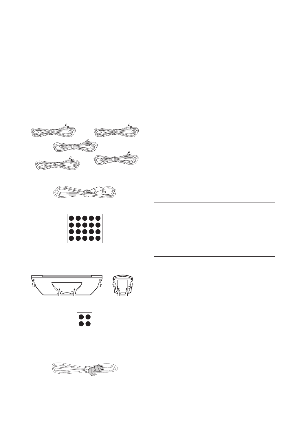
ACCESSORY ITEMS
Speaker cords x 5 (5mx3, 10mx2)
RCA plug cord x 1
Non-slip pads (5x3) (for Satellite)
(Stick the non-slip pads to the underside of the satellite and
center speakers as indicated by the arrows below.)
Non-slip pads (1x4) (for Subwoofer)
(Stick one non-slip pad in each corner of the underside of
the subwoofer.)
Power cord
BEFORE USE
• Thank you for buying this Pioneer product.
• Please read this operating guide through before using
your speaker system so you will know how to optimize
performance. After you have finished reading the
operating guide, store it in a safe place for future
reference.
• The nominal impedance of this speaker system is 6
Ω
ohms. Connect the speaker system to a stereo amplifier
with a load impedance ranging from 4 to 16 ohms (a
model with “4 – 16
Ω
” displayed on the speaker output
terminals).
• In order to prevent damage to the speaker system
resulting from input overload, please observe the
following precautions:
• Do not supply power to the speaker system in excess of
the maximum permissible input.
• When connecting or disconnecting pin-plugs, be sure
amplifier power is OFF.
• When using a graphic equalizer to emphasize loud
sounds over a high-frequency range, do not use
excessive amplifier volume.
• Do not try to force a low-powered amplifier to produce
loud volumes of sound (the amplifier’s harmonic
distortion will be increased, and you may damage the
speaker).
• Do not touch the speaker cone’s reverberating surfaces
as they may be damaged by external force.
CABINET MAINTENANCE
• Use a polishing cloth or dry cloth to wipe off dust and
dirt.
• When the cabinet is very dirty, clean with a soft cloth
dipped in some neutral cleanser diluted five or six times
with water, and then wipe again with a dry cloth. Do not
use furniture wax or cleaners.
• Never use thinners, benzine, insecticide sprays and
other chemicals on or near the cabinets, since these will
corrode the surfaces.
Center speaker
Front/Surround
speaker
These Satellite speakers and Subwoofer are
magnetically shielded.
However,depending on the installation location,color
distortion may occur if the speaker system is installed
extremely close to the screen off a television set.
If this happenscase,turn of the power switch of the
television set OFF,and turn it on after 15 to 30
minutes.If the problem persists,place the speaker
system away from the television set.
5
En
English
INSTALLATION
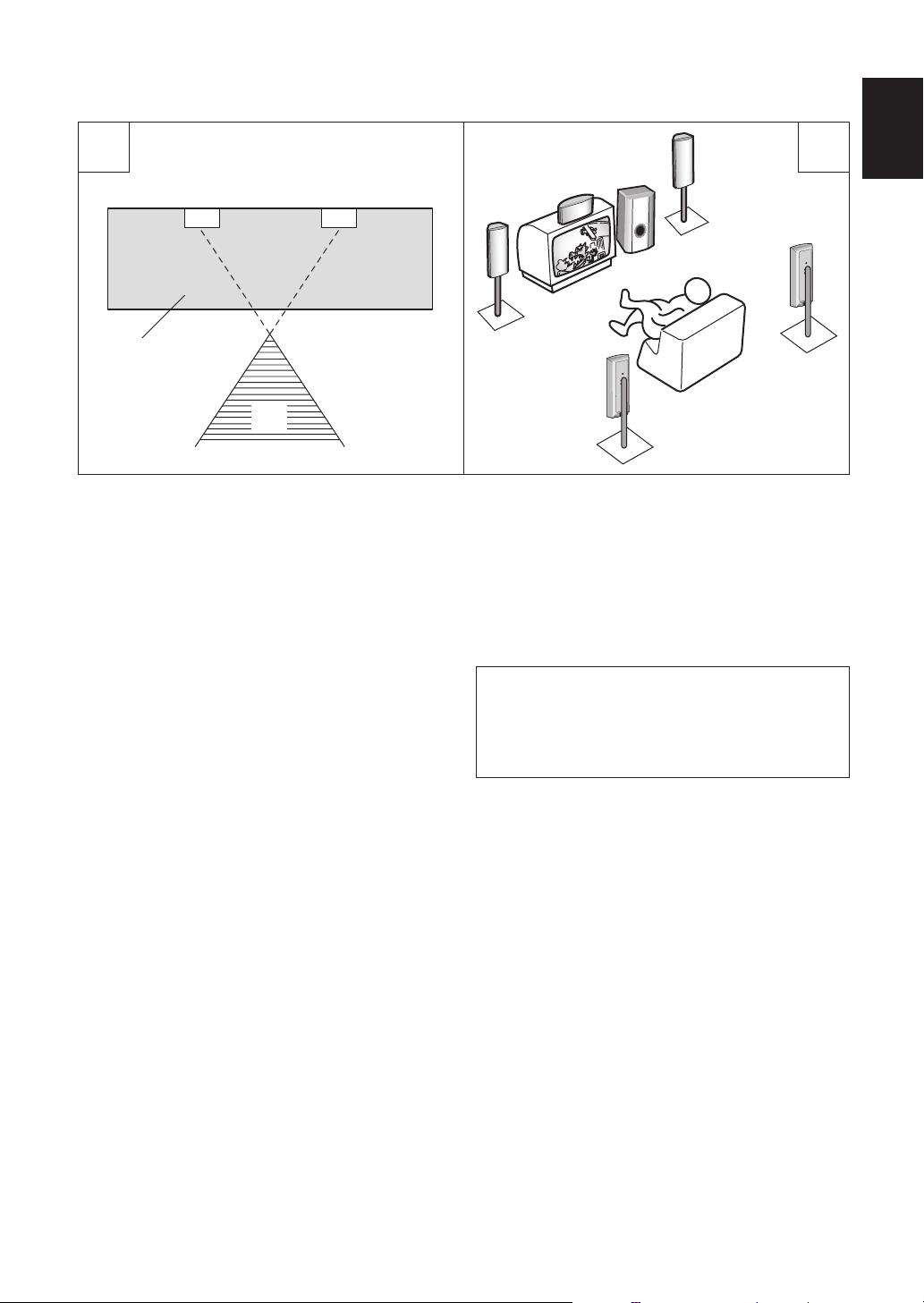
Speaker Installation
The subwoofer plays back the bass in monaural, making
use of the fact that the human ear loses the sense of
direction of low-pitched sound. Since the sense of direction
is lost, the subwoofer can be installed almost anywhere. If
it is installed too far away, however, the sound from the left
and right speakers may become unnatural.
Subwoofer Installation Criteria (Å
)
1
Left speaker
2
Right speaker
3
Recommended installation range for the subwoofer
4
Listening position
An example of speaker positioning (ı
)
1
Front left speaker
2
Center speaker
3
Front right speaker
4
Subwoofer
5
Listening area
6
Surround speaker left
7
Surround speaker right
NOTE:
• Position the left and right channel speakers at equal distances
from the TV set.
• Install the center speakers above or below the TV so that the
sound of the center channel is localized at the TV screen.
• The rear (surround) speakers are most effective when installed
in parallel locations directly to the side, or slightly behind, the
listener, at a level about 1 meter above the listener's ears.
AB
3
3
1
1
4
4
5
6
7
2
2
CAUTION:
When installing the center speaker on top of the TV, be sure
to secure it with tape or some other suitable means.
Otherwise, the speaker may fall from the TV due to external
shocks such as earthquakes, and it may lead to endangering
those nearby or damaging the speaker.
6
En
Installation Precautions
• Install the unit in a well-ventilated location where it will
not be exposed to high temperatures and high humidity.
• Do not place the unit near stoves or other heating
equipment or at locations exposed to direct sunlight, as
these can have an adverse effect on the cabinet and
internal components. Also, do not install the unit where
there is too much dust or high humidity, as these can
cause malfunctioning or breakdowns. (Avoid cooking
tables and other locations where the unit would be
exposed to heat, steam and soot.)
• Do not place heavy objects such as a television or TV
monitor on top of the unit.
• Keep the unit away from devices such as cassette decks
which are sensitive to magnetic fields
• Please install this unit away from the antenna cable of
the tuner, as noise can be caused with installation close
to the antenna cable. In such a case, use this unit at a
position away from the antenna and the antenna cable,
or when playback of extra bass is not required, switch off
the power for this unit.
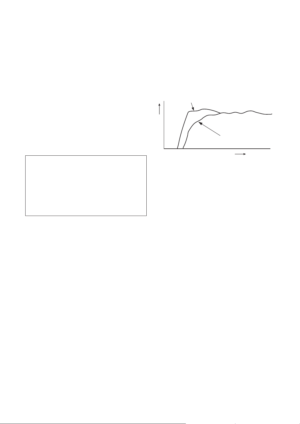
IN COMBINATION WITH
SPEAKERS
The frequency characteristics of the S-HS02 combined with
satellite speakers are shown below. As shown in these
figures, the low frequency range is improved.
• These special characteristics are obtained in an echoless
chamber. The effect of an additional subwoofer in an
ordinary listening room is better than the chart indicates
when positioned adequately.
• With playback of Dolby* Digital, establishment of a
special channel for the subwoofer is recommended; and
with playback of LFE (Low Frequency Effect: sound
effect like the rumbling of the earth, whose purpose is to
intensify the force of the video), the S-HS02 is especially
effective.
Dolby* Digital
Dolby Digital is the name of the Dolby Surround multi-
channel digital system that was developed from Dolby
Surround, as a continuation of Dolby Pro Logic Surround.
Dolby Digital is also referred to as a 5.1 channel system.
This is because it has 5 channels in the 20Hz – 20kHz
frequency range (front left and right, center, and rear left
and right) and an independent channel for the subwoofer.
The subwoofer channel is also referred to as LFE (Low
Frequency Effect).
The LFE channel is used according to individual tastes to
enhance the bass effect.
MAINTENANCE OF EXTERNAL
SURFACES
Use a polishing cloth or dry cloth to wipe off dust and dirt.
When the surfaces are very dirty, wipe with a soft cloth
dipped in some neutral cleanser diluted five or six times
with water, and wrung out well, and then wipe again with a
dry cloth. Do not use furniture wax or cleaners.
Never use thinners, benzine, insecticide sprays and other
chemicals on or near this unit, since these will corrode the
surfaces.
•
•
•
RESPONC (dB)
Satellite speaker + Subwoofer
Satellite
FREQUENCY (Hz)
7
En
English
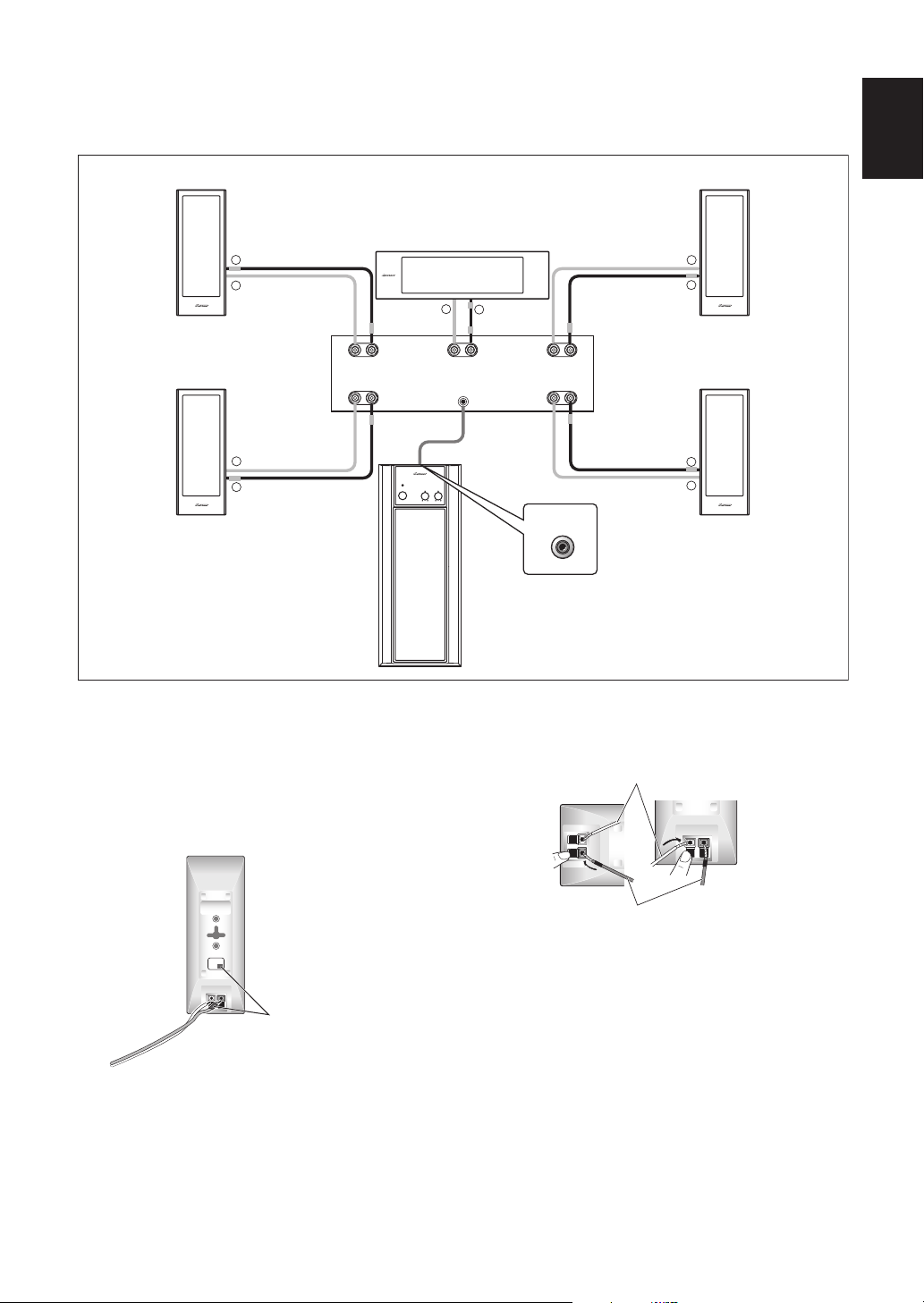
CONNECTIONS
Before making or changing the connections, switch off the power switch and disconnect the power cord from the
AC outlet.
1 Set the amplifier’s power switch to OFF.
2 Connect accessory speaker cords to the
input terminals at the rear of the speaker
system using the color-coded indicators.
Connect the cord with the colored sleeve to the
terminal and the cord with no marking to the
terminal. Bear in mind that the red input terminal has a
“
” polarity, and the other terminal has a “
” polarity.
Depress the input terminal lever, and insert the tip of
the cord into the hole and then release the lever so that
it springs back into position.
3 Connect the speaker cord to the
amplifier’s speaker output terminals in
the same way.
Your amplifier is unlikely to have the same color-coding
system, but you can identify which color goes with
which speaker by referring to the illustration at the top
of this page.
NOTES:
• Make sure that the speaker cords are connected to the
terminals securely. Insecure connections may cause not
only sound to be interrupted and noise to be generated
but also the cords to be shorted and the amplifier to
break down.
+++
+
––
–
–
–
+
+
+
–
–
+
–
+
–
+
–
FRONT FRONT
SURROUND
CENTER
SUBWOOFER
PREOUT
SURROUND
LEFTRIGHT
VOLUMECROSSOVER
STANDBY/ON
POWER
LINE LEVEL
INPUT
Front right speaker
Surround speaker right
Front left speaker
Surround speaker left
Subwoofer
Center speaker
Red sleeve
Grey sleeve
White sleeve
Green
sleeve
Blue sleeve
Match the colored
label on the speaker's
rear panel with the
color of the sleeve
at the end of the
speaker cord.
Connect the speaker cord with no
marking to the terminal.
Connect the speaker cord with the
colored sleeve to the terminal.
8
En
• If listening to a stereo performance with the speaker
system connected to a stereo amplifier and you find that
the bass is insufficient, the sound is not spread out and
there is no stereo effect; the cords of one of the speaker
systems have been plugged into the wrong polarity
terminals.
• Viewed from the front, connect the right-side speaker
system to the right channel (R) of amplifier’s speaker
output terminals, and the left-side speaker system to the
left channel (L).
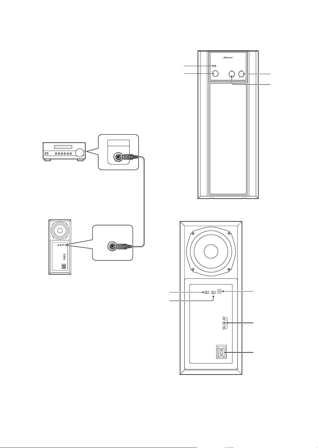
LINE LEVEL CONNECTION
This connection is for a stereo amplifier or receiver
equipped with a SUBWOOFER PRE-OUT terminal.
Connect to the LINE LEVEL INPUT terminal on this unit,
using the specially provided RCA plug cord.
NOTE:
When connected to the PRE-OUT terminal for surround
center channel on the stereo amplifier or receiver, the bass
is heard only on the center channel, so it will be insufficient.
PANEL FACILITIES
LINE LEVEL
INPUT
AUTO
STANDBY
PHASE
0 180
OFF ON
AC IN
LINE LEVEL
INPUT
SUB WOOFER
PREOUT
Stereo amplifier or Reseiver
Supplied RCA plug cord
Subwoofer (Rear Panel)
240V
220-
230V
110-
127V
FRONT PANEL
VOLUMECROSSOVER
STANDBY/ON
POWER
3
4
1
2
LINE LEVEL
INPUT
AUTO
STANDBY
PHASE
0 180OFF ON
AC IN
240V
220-
230V
110-
127V
6
7
5
8
LINE VOLTAGE
SELECTOR
SWITCH
REAR PANEL

9
En
English
1 Power indicator (STANDBY/ON)
Lights red when the power has been switched ON.
Lights green when the speakers receive an audio
signal. If the power is switched OFF only briefly, the
indicator lights green when power is restored. If no
signal is present for more than 8 minutes, the
subwoofer automatically reverts to standby mode and
the power indicator lights red. If, subsequently, a signal
is received, power automatically comes back on and
the power indicator lights green.
2 POWER switch
Pressing once switches the unit ON. Press again to
switch OFF.
NOTE:
If you are planning on switching the unit OFF for a long
period of time, make sure to check that the indicator light
has gone out after switching OFF.
3 Volume knob (LEVEL)
Sets the subwoofer volume.
• Turn the knob slowly from the MIN position.
• With this unit, the bass level can be independently set,
so do not turn up the bass on the stereo amplifier.
4 Crossover knob (CROSSOVER)
Sets the high limit of the frequency played back by the
subwoofer. Set to MAX when using the supplied
speaker system.
Setting Criteria
MIN.................. when the diameter of the left/right
speakers is 20 cm or more.
CENTER........... when the diameter of the left/right
speakers is 10-25 cm.
MAX................. when the diameter of the left/right
speakers is 12 cm or less.
5 Line Level Input terminal
(LINE LEVEL INPUT)
Connects to the stereo amplifier’s SUBWOOFER PRE-
OUT terminal, with the specially provided RCA plug
cord.
6 Auto Standby switch
(AUTO STANDBY)
Switches the Auto Standby feature on/off.
Auto Standby
When switched
ON
(the default setting is
OFF
), the
Auto Standby feature becomes active. In this mode, if
there is no input signal for eight minutes the system
automatically switches to standby. The power is
automatically switched on again if an input signal is
detected.
NOTE
• There may be cases where a connected component
outputs noise or some other non-audio signal which
causes this system to automatically power on when in
Auto Standby mode. If this happens, switch off the Auto
Standby mode and switch the system on/off manually.
7 Phase switch (PHASE 0
°°
°°
/180
°°
°°
)
When depressed (180
°
), the output phase becomes
the reverse of the input signal, and when raised (0
°
), it
is in the sane phase as the input signal.
•
Normally, the switch is set to ( 0
°
).
But when the sound connection between the subwoofer
and the left and right speakers sounds unnatural, tyr
switching to 180
°
and set the switch in the position
where the sound is natural.
8 AC INLET
• Connect the power cord to tje powered subwoofer
unit’s AC INLET.
• Connect the power cord to a AC socket.
OPERATION
For details regarding operating part functions, refer to
pages 8-9.
1 Turn the POWER switch (22
22
) ON.
• If the unit cannot be connected to the stereo amplifier or
receiver, turn the power to the stereo amplifier or
receiver ON before turning the power to the unit ON.
When turning the power OFF, turn the power to the unit
OFF before turning the power to the stereo amplifier or
receiver OFF.
2 Operate the stereo amplifier or receiver
and adjust the volume of the left/right
speakers.
3 Adjust the strength of the bass with the
Volume knob (33
33
).
When necessary, operate the Crossover knob (4
) and
PHASE switch (7
), and then adjust with the Volume
Knob (3
).
AC IN

10
En
TROUBLESHOOTING
Incorrect operations are often mistaken for trouble and malfunctions. If you think that there is something wrong with this
component, check the points below. Sometimes the trouble may lie in another component. Investigate the other
components and electrical appliances being used If the trouble cannot be rectified even after exercising the checks listed
below, ask your nearest PIONEER authorized service center or your dealer to carry out repair work.
SPECIFICATIONS
Front, Surround Speaker:
Enclosure .....................................Closed Box, bookshelf type
System...................................................... 11 x 7 cm cone type
Nominal Impedance............................................................ 6
Ω
Frequency Range..................................... 120 Hz to 25,000 Hz
Sensitivity ......................................84.5 dB/W at 1 m distance
Maximum input ................................................................ 75 W
External Dimensions ...................82(W) x 210(H) x 84(D) mm
Weight(without package)................................................0.7 kg
Center Speaker:
Enclosure .....................................Closed Box, bookshelf type
System...................................................... 11 x 7 cm cone type
Nominal Impedance............................................................ 6
Ω
Frequency Range..................................... 120 Hz to 25,000 Hz
Sensitivity ......................................84.5 dB/W at 1 m distance
Maximum input ................................................................ 75 W
External Dimensions ....................300(W) x 82(H) x84(D) mm
Weight(without package)................................................0.8 kg
Subwoofer:
Power Requirements.............. AC110-127V/220-230V/240V~
(swichable), 50/60 Hz
Power Consumption....................................................... 100W
Outline Dimensions.................165(W) x 405(H) x 325(D) mm
Weight(without package) ...............................................9.4 kg
Power Amplifier:
Continous Power Output (RMS) .................................... 100W
(100Hz, T.H.D 10%, 6
Ω
)
Total Harmonic Distortion
.................................................. 0.5 % (40 – 200 Hz, 6
Ω
, 25 W)
Power consumption (an energy-saving standby mode)
....................................................................................0.5W less
• Above specifications are for when power supply is 230V.
Input (sensitivity at 100 Hz/impedance)
LINE LEVEL (RCA jack)...................................... 160 mV/50 k
Ω
CROSSOVER Frequency........................................... 50-200Hz
(continuously variable)
Speaker:
Enclosure .............................. Bass-reflex, floor-standing type
System............................................................13 cm cone type
Accessory Parts
:
Speaker cords x 5 (5mx3, 10mx2)
RCA plug cord x 1
Non-slip pads (5x4, (1x4))
Operating instructions x 1
NOTE:
Specifications and design subject to possible modification without
notice, due to improvements.
SYMPTOM CAUSE REMEDY
1 No power is being supplied.
(Indicator does not light up when
power switch is turned on.)
• Power supply plug is not correctly
inserted.
• Insert plug securely.
2 No sound. (Indicator is lit.)
• Connection of accessory RCA plug
cord is wrong or disconnected.
• LEVEL knob is set to MIN.
• Check again and connect correctly.
• Turn clockwise slowly.
3 Sound is distorted. • Level is too high. • Turn the LEVEL knob counter-
clockwise to lower the level.
4 Howling noise occurs. • Subwoofer level is set too high. • Place the subwoofer a good distance
from speakers. Turn the LEVEL knob
counter-clockwise to lower the
volume.
5 Much noise when listening to AM or
FM broadcasts.
• The AM loop antenna or the FM
indoor antenna is close to this unit.
• Increase the distance between the
AM or FM antenna (for indoor use)
and this unit.
6 System doesn’t switch to standby. • Auto Standby is switched off. • Switch on Auto Standby.
 Loading...