


GM-ME300X4C

En(2/10)
Before you start
En(1/10)
Owner’s Manual
Mode d’emploi
Manual de instrucciones
MARINE 4-CHANNEL AMPLIFIER
AMPLIFICATEUR 4 CANAUX MARIN
AMPLIFICADOR MARINO DE 4 CANALES
GM-ME300X4C
English
Français
Español
https://www.pioneerelectronics.com
https://www.pioneerelectronics.ca
PIONEER CORPORATION
28-8,
Honkomagome 2-chome, Bunkyo-ku,
T
okyo 113-0021, JAPA N
PIONEER
ELECTRONICS (USA) INC.
P.
O. Box 1540, Long Beach, California 90801-1540,U
.S.A.
TEL: (800) 421-1404
<A1-000030-9L-A> UC
<KNZZ20K>
© 2020 PION EER CORPORATION.
Thank you
for purchasing this PIONEER
product
To ensure proper use, please read through this
manual before using this product. It is espe
-
cially important that you read and observe
WARNINGS and CAUTIONS in this manual.
Please keep the manual in a safe and accessi-
ble place for future reference.
Information to User
Alteration or modifications carried out without
appropriate authorization may invalidate the
user’s right to operate the equipment.
Note
This equipment has been tested and found
to comply with the limits for a Class B digital
device, pursuant to Part 15 of the FCC Rules.
These limits are designed to provide reason
-
able protection against harmful interference
i
n a residential installation. This equipment
generates, uses and can radiate radio fre
-
quency energy and, if not installed and used
i
n accordance with the instructions, may
cause harmful interference to radio commu
-
nications. However, there is no guarantee
th
at interference will not occur in a particu-
lar installation. If this equipment does cause
h
armful interference to radio or television
reception, which can be determined by
turning the equipment off and on, the user is
encouraged to try to correct the interference
by one or more of the following measures:
— Reorient or relocate the receiving
antenna.
— Increase the separation between the
equipment and receiver.
— Connect the equipment into an out-
let on a circuit different from that to
w
hich the receiver is connected.
— Consult the dealer or an experienced
radio/TV technician for help.
FEDERAL COMMUNICATIONS
COMMISSION SUPPLIER’S DECLARATION
OF CONFORMITY
Product Name: Marine 4-channel Amplifier
Model Number: GM-ME300X4C
Responsible Party Name: PIONEER
ELECTRONICS (USA) INC.
SERVICE SUPPORT DIVISION
Address: 2050 W. 190TH STREET, SUITE 100,
TORRANCE, CA 90504, U.S.A.
Phone: 1-800-421-1404
URL:
https://www.pioneerelectronics.com
After-sales service for
Pioneer products
Please contact the authorized Pioneer dealer
from which you purchased this unit or an
authorized Pioneer service company for after-
sales service or questions you may have about
the product. You may contact Pioneer directly
as follows:
Do not ship your unit in for repair
without contacting Pioneer rst.
Units sent without a return authoriza
-
tion number will be refused.
USA & CANADA
Pioneer Electronics (USA) Inc.
CUSTOMER SUPPORT DIVISION
P.O. Box 1760
Long Beach, CA 90801-1760 U.S.A.
80 0-421-140 4
For warranty information, please see the
Limited Warranty sheet included with this unit.
Visit our website
U.S.:
https://www.pioneerelectronics.com
Canada:
https://www.pioneerelectronics.ca
Learn about product updates (such as
firmware updates) for your product.
Register your product.
Access owner’s manuals, spare parts infor-
mation, service information, and much more.
The Safety of Your Ears is in
Your Hands
Get the most out of your equipment by playing
it at a safe level—a level that lets the sound
come through clearly without annoying blar
-
ing or distortion and, most importantly, with-
out affecting your sensitive hearing. Sound
c
an be deceiving. Over time, your hearing
“comfort level” adapts to higher volumes of
sound, so what sounds “normal” can actually
be loud and harmful to your hearing. Guard
against this by setting your equipment at a
safe level BEFORE your hearing adapts.
ESTABLISH A SAFE LEVEL:
Set your volume control at a low setting.
Slowly increase the sound until you can
hear it comfortably and clearly, without
distortion.
Once you have established a comfortable
sound level, set the dial and leave it there.
BE SURE TO OBSERVE THE FOLLOWING
GUIDELINES:
Do not turn up the volume so high that you
can’t hear what’s around you.
Use caution or temporarily discontinue use
in potentially hazardous situations.
Do not use headphones while operating a
boat; the use of headphones may create a
traffic hazard and is illegal in many areas.
Before connecting/installing
the amplier
WARNING
To prevent fire hazard, the heatsink should never
be covered (such as by paper, material, etc.).
This unit is for boats with a 12 V battery and
negative grounding. Before installing, check
the battery voltage.
When installing this unit, make sure to con-
nect the ground wire first. Ensure that the
g
round wire is properly connected to the neg
-
ative ground circuit of the boat. Use adequate
gauge, marine grade electrical wire that has
been properly terminated for marine use to
make a direct connection to the negative bus
bar or negative ground distribution system.
Do not attempt to ground the amplifier using
the mounting screws.
Use fused marine grade battery wire (sold
separately) of adequate gauge that has been
properly terminated for marine use to make
a direct connection to the positive bus bar or
positive distribution system.
If the screw for the ground wire loos
-
ens or falls out, it could result in re,
smoke or malfunction.
Always use a fuse of the rating prescribed.
The use of an improper fuse could result in
overheating and smoke, damage to the prod
-
uct, and injury, including burns.
Check all electrical and signal connections
(power, ground, amplifier, speaker, etc.) if
amplifier fuse or battery wire fuse blows.
Resolve any loose or short circuited connec
-
tions, then replace the blown fuse with an
i
dentical value equivalent.
Always install the amplifier on an even sur
-
face. Do not install the amplifier on a surface
t
hat is uneven or has a protrusion. Doing so
could result in malfunction.
When installing the amplifier, do not allow
parts such as extra screws to get caught
between the amplifier and the boat. Doing so
could cause malfunction.
In the event of any abnormality, the power
supply to the amplifier may cut off to pre
-
vent equipment malfunction. If this occurs,
s
witch the system power off and check all
electrical and signal connections (power,
ground, amplifier, speaker, etc.) for loose or
short circuited connections. If you are unable
to determine the cause, please contact your
dealer.
Always disconnect the negative * terminal
of the battery before making any electrical or
signal connections to avoid the risk of electric
shock or short circuit during installation.
En(6/10)
En(5/10)
En(4/ 10)
En(3/10)
About the protection function
This product has a protection function. If this
product detects something abnormal, the Power/
Protect indicator will turn red and the operation
of amplifier will be stopped.
Possible causes include:
— When the temperature inside the product
becomes high
— When speaker output detects an abnormality
— When the supply voltage is out of
specification
Important (Serial number)
The serial number is located on the bottom of
this unit. Be sure to record this number on the
enclosed warranty card before installation.
Setting the unit
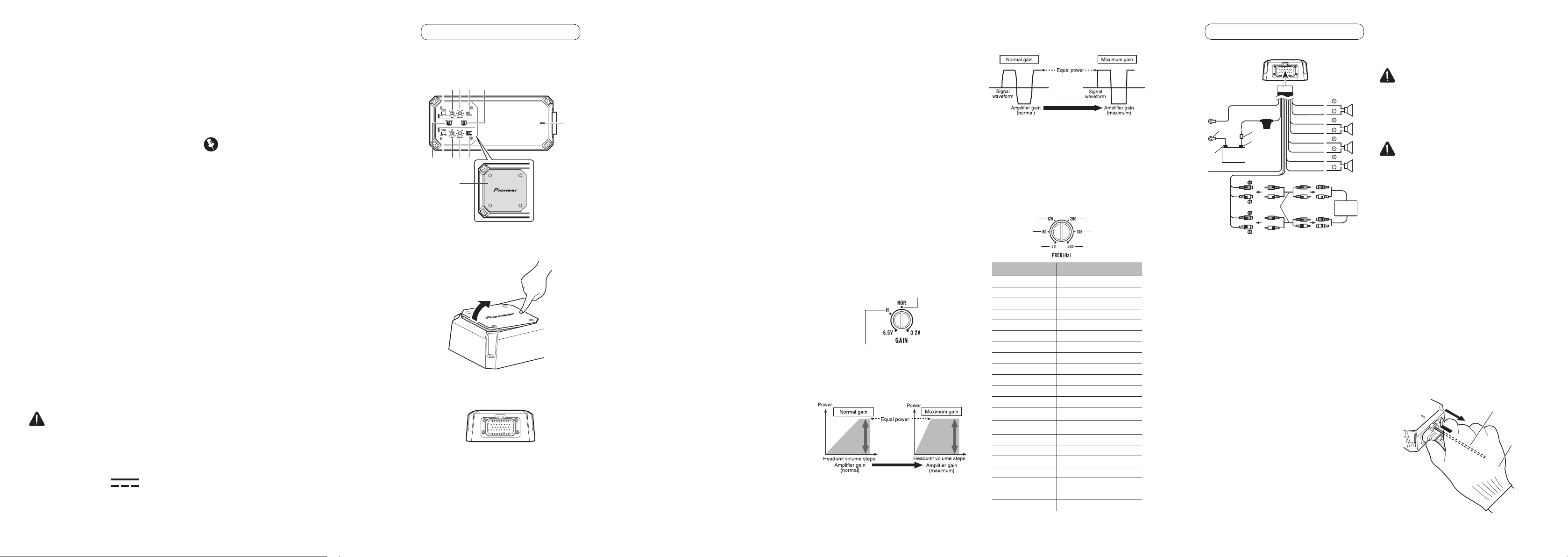
What’s what
Top side
1 2 3 4
1 2 3 4
5
6
7
Top panel
cover
Use the supplied wrench to remove the four
screws and detach the top panel cover. Be
sure not to lose the removed screws.
1
2
Use a flathead screwdriver to adjust the
switch if needed.
Right side
1
SPEAKER SETTING switch
Switch the output power according to the
connected speaker. When a subwoofer
is connected, select MONO. When a full
range speaker is connected, select 2CH.
2 GAIN volume
Adjusting gain volume CH A (channel
A) and CH B (channel B) helps align the
headunit output to the Pioneer ampli
-
fier. Default setting is the NO
R (normal)
position.
If the output remains low even when the
headunit volume is turned up, turn the
volume to a lower level (clockwise). If dis
-
tortion occurs when the headunit volume is
t
urned up, turn these volumes to a higher
level (counterclockwise).
If using only one input plug, set the gain
volumes for speaker outputs A and B to
the same position.
For use with an RCA equipped stereo
(standard output of 500 mV), set to the
NOR (normal) position. For use with an
RCA equipped Pioneer headunit with
maximum output of 4 V or more, adjust
level to match that of the stereo output.
For use with an RCA equipped headunit
with output of 4 V, set to the H (High)
position.
3
FREQ (Hz) (cutoff frequency)
The cutoff frequency is selectable from
50 Hz to 500 Hz when the LPF/HPF select
switch is set to either LPF or HPF. For more
information, refer to
the Precise Frequency
Selection Chart.
4 LPF (low-pass lter)/HPF (high-pass
lter) select switch
S
witch the settings based on the con-
nected speaker.
When a subwoofer is connected:
Select L
PF. This eliminates high range
frequencies and limits output to only
low range frequencies.
When a full range speaker is connected:
Select H
PF or OFF. HPF eliminates
low range frequencies and limits
output to only high frequencies. OFF
bypasses the LPF/HPF and outputs all
frequencies.
5 INPUT SENS switch
Select RCA for RCA level input signals or SP
(Speaker) for Speaker level input signals.
6 INPUT SELECT switch
Select 2CH for two-channel input or 4CH
for four–channel input.
7 Power/Protect indicator
The power indicator lights blue to indicate
power ON.
The power indicator lights red to
indicate protection mode has been
engaged.
Setting gain properly
A protective function is included to avoid
malfunction of the unit and/or speakers
due to excessive output, improper use or
improper connection.
When outputting high volume sound etc.,
this function may cut off the output for a
few seconds as a normal function. Output
will be restored when the volume of the
headunit is turned down.
A cut in sound output may indicate
improper setting of the gain volume. To
ensure continuous sound output with the
headunit at a high volume, set the ampli
-
fier gain volume to a level appropriate
f
or the preout maximum output level of
the headunit, so that volume can remain
unchanged and to avoid distortion caused
by signal waveform clipping at the amplifier
input.
Even with correct volume and gain set
-
tings, the unit sound may cut out period-
ically. In such cases, please contact an
a
uthorized Pioneer Service Company.
Gain volume of this unit
0.5 V (Maximum preout level=2 V)
Maximum preout level=4V
Above illustration shows NOR (normal) gain
setting.
Relationship between amplier gain
and headunit output power
If amplifier gain is raised improperly, this will
simply increase distortion, with little increase
in power.
Signal waveform when outputting
at high volume using amplier gain
volume
If the signal waveform is distorted due to high
output, even if the amplifier gain is raised, the
output power will change only slightly.
Precise Frequency Selection
Chart
The numbers in the illustration correspond to
the Step Number.
No.1
No.5
No.9
No.13
No.17
No.21
Step Number Frequency (Hz)
1 50
2 56
3 63
4 71.5
5 80
6 90
7 100
8 113
9 125
10 143
11 160
12 180
13 200
14 225
15 250
16 285
17 315
18 335
19 400
20 450
21 500
Connecting the units
Connection diagram
i
j
k
p
l
n
m
o
1
3
2
4
5
6
7
8
9
a
q
b
c
d
f
e
g
h
1 To power cable input
2 White: CH-A, Left
3 White/black: CH-A, Left *
4 Gray: CH-A, Right
5 Gray/black: CH-A, Right *
6 Green: CH-B, Left
7 Green/black: CH-B, Left *
8 Violet: CH-B, Right
9 Violet/black: CH-B, Right *
a CH-A Speaker Left
b CH-A Speaker Right
c CH-B Speaker Left
d CH-B Speaker Right
e CH-A RCA input
f CH-B RCA input
g Connecting wire with RCA pin plugs (sold
separately)
h Headunit with RCA output jacks (sold separately)
i Black (chassis ground)
Connect to a clean, paint-free metal location.
j Red
k Fuse (30 A)
l Ground wire, Terminal (sold separately)
The ground wires must be the same size as
the battery wire.
m Battery wire with Fuse [more than 30A]
(sold separately)
The maximum length of the wire between
the fuse and the positive
terminal of the
battery is 30 cm (12 in.).
n Positive terminal
o Negative (*) terminal
p Battery (sold separately)
q System remote control wire
Note
INPUT SELECT switch must be set. For details,
see
Setting the unit
.
Before connecting the amplier
WARNING
Secure the wiring with cable clamps or adhe-
sive tape. To protect the wiring, wrap sections
in contact with metal parts in adhesive tape.
Never cut the insulation of the power supply
to feed power to other equipment. Current
capacity of the wire is limited.
CAUTION
If the system remote control wire of the
amplifier is connected to the power terminal
via the ignition switch (12 V DC), the amplifier
will remain on with the ignition whether the
headunit is on or off, which may exhaust
battery if the engine is at rest or idling.
Install and route the separately sold marine
grade battery wire, marine grade ground wire,
speaker wires and the amplifier as far away
as possible from the radio antenna, antenna
cable, tuner and any communications equip-
ment and wiring.
The point of connector
attachment/detachment
Push in the connector until a clicking sound
is heard, confirming a secure connection.
How to remove the connector:
(1) Insert the supplied tool into the lock part of
the connector.
(2) Gently raise the release locking tab to
separate the connector.
Note: Attempting to remove the connector
by force or pulling from the wire harness can
cause damage.
To avoid injury, use a work
glove to help with gripping the tool.
2
1
Supplied tool
Work glove
- Continue to page 7/10 -
Do not attempt to disassemble or modify
this unit. Doing so may result in fire, electric
shock or other malfunction. Damage or
defects resulting from alterations or modifica
-
tions not authorized in writing by Pioneer are
excluded from limited warranty coverage.
Do not install the amplifier in a location
exposed to direct sunlight or excessive heat,
humidity or dust.
While this amplifier is designed to be water-re-
sistant, it should never be submerged under
w
ater or subjected to high-pressure water
spray.
Install the amplifier in a dry and well-ventilated
environment,
where other equipment will not
interfere with it.
When drilling holes in the chassis for instal-
lation, take precautions so as not to contact,
d
amage or obstruct pipes, fuel lines, tanks or
electrical wiring. Failure to take such precau
-
tions may result in fire.
To ensure proper heat dissipation of the
amplifier, ensure the following during
installation:
— Allow adequate space above the amplifier
for proper ventilation.
— Do not mount the amplifier in the engine
compartment or in any areas of extreme
heat.
— Do not cover the amplifier.
Ask your dealer or installation profes
-
sional to install/uninstall this prod-
uct. Incorrect installation can create
d
angerous hazards or interfere with
boat operation.
Keep small items such as bolts, screws and
tools out of the reach of children. Swallowing
can cause serious injury. If swallowed, con
-
sult a doctor immediately.
CAUTION
Always keep the volume low enough to hear
outside sounds.
Extended use of the amplifier while the
engine is at rest or idling may exhaust the
battery.
The graphical symbol
placed on the
product means this is an electronic product
requiring direct current electrical power.
En(10/10)
En(9/10)
En(8/10)
En( 7/10)
If you lose the supplied tool, use a flat screwdriver with a tip width of 3 mm or less as a substitute.
Max 3 mm (1/8 in.)
About suitable specication of speaker
Regarding the speaker to be connected to the amplifier, use a speaker having a rated input capac-
ity more than the rated output capacity of the amplifier. If this condition is not met, there is a risk
o
f fire, smoke, or damage. The speaker impedance is 2Ω to 8Ω.
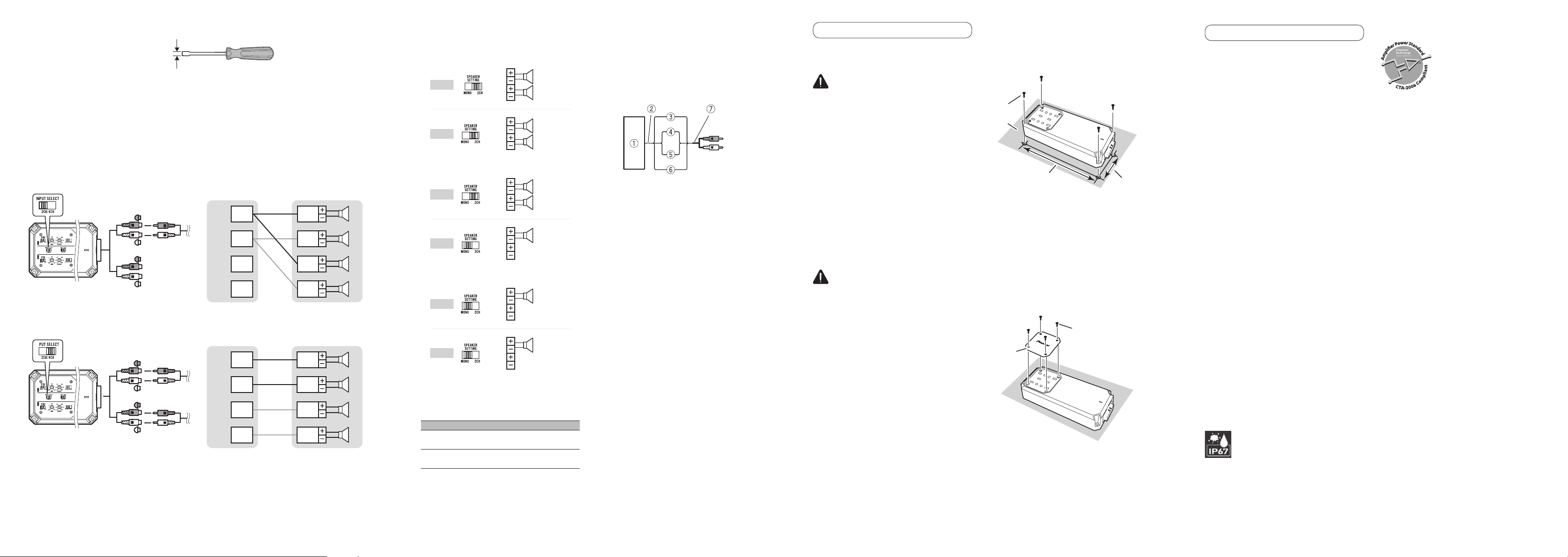
Speaker setting and I/O
Corresponding I/O for the number of input channels
Input: Two-channel / Output: Four-channel
Slide INPUT SELECT switch to 2CH position.
CH-A
CH-A
CH-B
CH-B
CH1 CH1
CH2
CH3
CH4
CH2
CH3
CH4
INPUT OUTPUT
(L)
(L)
(L)
(L)
(R)
(R)
(R)
(R)
Input: Four-channel / Output: Four-channel
Slide INPUT SELECT switch to 4CH position.
CH-A
CH-A
CH-B
CH-B
CH1 CH1
CH2
CH3
CH4
CH2
CH3
CH4
INPUT OUTPUT
(L)
(L)
(L)
(L)
(R)
(R)
(R)
(R)
Example of speaker setting and speaker
connection
Four channel output
CH-A
CH-B
STEREO
STEREO
STEREO
STEREO
(L)
(L)
(R)
(R)
Three channel output
CH-A
CH-B
STEREO
MONO
STEREO
(L)
(L)
(R)
(R)
Two channel output
CH-A
CH-B
MONO
MONO
(L)
(L)
(R)
(R)
When in MONO connection, a monaural
signal is output, which is a mix of the left and
right channel signals.
Speaker setting and power output
MONO 2CH
2 W
— 75 W
4 W
150 W 75 W
Connections when using the
speaker input wire
Connect the headunit speaker output wires to
the amplifier using the supplied speaker input
wire with RCA pin cord.
Make sure to switch the INPUT SENS switch
to SP (speaker).
1 Headunit
2 Speaker output
3 Red: Right
4 Black: Right *
5 Black: Left *
6 White: Left
7 Speaker input wire with RCA pin cord to
the RCA input jack of this unit
Note
If speaker input wires from a headunit are
connected to this amplifier, the amplifier will
automatically turn on when the headunit is
turned on. When the headunit is turned off,
the amplifier turns off automatically. This
function may not work with some headunits.
In such cases, make sure that the front chan-
nel is connected correctly. If the function still
does not work, please use a system remote
control wire (sold separately). If multiple
amplifiers are to be connected together
synchronously, connect the headunit and all
amplifiers via the system remote control wire.
Installation
Before installing the
amplier
WARNING
To ensure proper installation, use the sup-
plied parts in the manner specified. If any
parts other than those supplied are used, they
may damage internal parts of the amplifier or
become loose, causing the amplifier to shut
down.
Do not install:
— On surfaces that could become loose
if the boat stops suddenly (chassis
recommended).
— In places where it may interfere with the
boat’s operation.
Install tapping screws in such a way that the
screw tip does not touch any wire. This is
important to prevent wires from being cut by
vibration of the boat, which can result in fire.
Make sure that wires do not get caught in
the sliding mechanism or touch the legs of a
person in the boat as short-circuit may result.
CAUTION
Place all cables away from hot places, such
as near the heater outlet.
The optimal installation location differs
depending on the boat model. Secure the
amplifier at a sufficiently rigid location.
Check all connections and systems before
final installation.
Example of installation on
the chassis
1 Place the amplier in the desired
installation location.
Insert the supplied tapping screws (4 mm
× 25 mm) into the screw holes and push
on the screws with a screwdriver so they
make an imprint where the installation
holes are to be located.
2 Drill 2.5 mm (1/8 in.) diameter holes in
the mounting surface.
3 Install the amplier with the use of
supplied tapping screws (4 mm × 25
mm).
1
②
4
3
1 Tapping-screws (4 mm × 25 mm)
(5/32 in.
× 1 in.)
2 Installation surface
3 Hole-to-hole distance: 224.4 mm (8-27/32 in.)
4 Hole-to-hole distance: 86.4 mm (3-13/32 in.)
4 Attach the top panel cover.
Use the removed screws to attach the top
panel cover (fastening torque 0.4 to 0.7
N·m).
Attach the top panel cover in the same
orientation as the main unit installation
orientation.
1
2
1 Screws
2 Top panel cover
Additional information
Specications
Power source ...................... 14.4 V DC (10.8 V to 15.1 V
allowable)
Grounding system .............. Negative type
Current consumption ......... 26 A (at continuous power,
4 W)
A
verage current consumption
.......................................... 5.8 A (4 W for four channels)
6.6 A (2 W
for four channels)
Fuse ..................................... 30 A
Dimensions (W × H × D) .. 243 mm × 46.8 mm ×
105 mm
(9-5/8 in. × 1-7/8 in. ×
4-1/8 in.)
W
eight ................................. 1.4 kg (3.1 lbs)
(Leads for wiring not
in
cluded)
Continuous power output .. 75 W × 4 (at 14.4 V, 4 W,
20 Hz to 20 kHz , ≤ 1 % THD)
75 W × 4 (at 14.4 V, 2 W,
1 kHz, ≤ 1 % THD)
150 W × 2 (at 14.4 V, 4 W,
MON O, 1 kHz, ≤ 1 % THD)
Lo
ad impedance ................. 4 W (2 W to 8 W allowable)
Frequency response ........... 10 Hz to 50 kHz (+0 dB,
–3 dB)
S
ignal-to-noise ratio ........... 95 dB (IHF-A network)
Distortion ............................ 0. 05 % (10 W, 1 kHz)
Low pass filter:
Cutoff frequency ......... 50 Hz to 500 Hz
Cutoff slope ................. –12 dB/oct
High pass filter:
Cutoff frequency ......... 50 Hz to 500 Hz
Cutoff slope ................. –12 dB/oct
Gain volume:
RCA .............................. 0.2 V to 6.5 V
Speaker ........................ 0.8 V to 16 V
Maximum input level / impedance:
RCA .............................. 6.5 V / 25 kW
Speaker ........................ 16 V / 12 kW
Waterproof .......................... JIS/IEC protection class
7 (IPX7) equivalent
(self-certified)
Dustproof ............................ JIS/IEC protection class
6 (IP6X) equivalent
(self-certified)
CTA2006 Specications
Power output....................... 75 W RMS × 4 Channels (at
14.4 V, 4 W, 20 Hz to 20 kHz
and ≤ 1 % THD+N)
S/N ratio .............................. 75 dBA (reference: 1 W into
4 W)
Accessories
Power cable × 1
Speaker line input RCA cable × 2
Hexagonal wrench × 1
Mounting screw (4 × 25 mm) × 4
Supplied tool × 1
Notes
Specifications and design are subject to mod-
ification without notice.
The average current consumption is nearly
the maximum current consumption by this
unit when an audio signal is input. Use this
value when working out total current con-
sumption by multiple power amplifiers.
 Loading...