


INSTALLATION MANUAL
DVH-P6050UB
|
English |
MANUAL INSTALLATION |
Nederlands Italiano Français |
|
|

Contents |
|
|
Connecting the Units |
||
|
|
|
Connecting the Units ................................ |
1 |
Power cable connection .................................... |
3 |
Connecting to separately sold power amp ........ |
5 |
When connecting with a multi-channel |
|
processor .................................................... |
7 |
Connecting and installing the optical cable |
|
connection box .......................................... |
8 |
When using a display connected video |
|
outputs ........................................................ |
9 |
When connecting with a rear view camera |
.... 10 |
Installation ................................................ |
11 |
DIN Front/Rear-mount .................................... |
12 |
DIN Front-mount ............................................ |
12 |
DIN Rear-mount .............................................. |
13 |
Note:
•When this unit is installed in a vehicle without ACC (accessory) position on the ignition switch, red cable must be wired to the terminal that can detect the operation of the ignition key. Otherwise, battery drain may result.
|
|
CC |
|
|
|
|
|
|
|
|
|
F |
A |
O |
|
|
|
F |
O |
|
|
|
|
N |
|
N |
||||||
O |
F |
|
|
|
|
O |
F |
|
|
|
|
|
|
|
S |
|
|
|
S |
||
|
|
|
|
|
|
|
|
|
||
|
|
|
|
|
T |
|
|
|
|
T |
|
|
|
|
R |
A |
|
|
|
R |
A |
|
|
|
T |
|
|
|
T |
|
||
ACC position |
No ACC position |
|||||||||
•Use this unit in other than the following conditions could result in fire or malfunction.
—Vehicles with a 12-volt battery and negative grounding.
—Speakers with 50 W (output value) and 4 ohm to 8 ohm (impedance value).
•To prevent short-circuit, overheating or malfunction, be sure to follow the directions below.
—Disconnect the negative terminal of the battery before installation.
—Secure the wiring with cable clamps or adhesive tape. To protect the wiring, wrap adhesive tape around them where they lie against metal parts.
—Place all cables away from moving parts, such as gear shift and seat rails.
—Place all cables away from hot places, such as near the heater outlet.
—Do not pass the yellow cable through a hole into the engine compartment to connect to a battery.
—Cover any disconnected cable connectors with insulating tape.
—Do not remove RCA caps if RCA cables are not used.
—Do not shorten any cables.
—Never cut the insulation of the power cable of this unit in order to share the power to other equipment. Current capacity of the cable is limited.
—Use a fuse of the rating prescribed.
—Never wire the speaker negative cable directly to ground.
—Never band together multiple speaker’s nega-
tive cables.
1

•Control signal is output through blue/white cable when this unit is powered on. Connect it to an external power amp’s system remote control or the vehicle’s auto-antenna relay control terminal (max. 300 mA, 12 V DC). If the vehicle is equipped with a glass antenna, connect it to the antenna booster power supply terminal.
•Never connect blue/white cable to external power amp’s power terminal. Also, never connect it to the power terminal of the auto antenna. Otherwise, battery drain or malfunction may result.
•IP-BUS connectors are color-coded. Be sure to connect connectors of the same color.
•Black cable is ground. This cable and other product’s ground cable (especially, high-current products such as power amp) must be wired separately. Otherwise, fire or malfunction may result if they are accidentally detached.
Nederlands Italiano Français Deutsch Español English
2
Connecting the Units
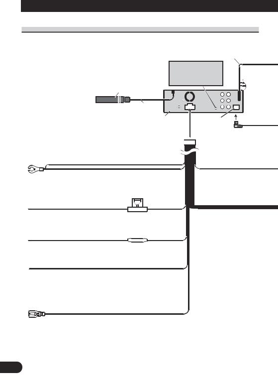
Power cable connection
AUX jack (3.5 ø) |
20 cm |
Use a mini plug cable to connect with auxiliary device.
Antenna jack
15 cm
This product
Black (chassis ground)
Connect to a clean, paint-free metal location.
Fuse (10 A)
Yellow
Connect to the constant 12 V supply terminal.
Fuse resistor
Red
Connect to terminal controlled by ignition switch (12 V DC).
Yellow/black
If you use an equipment with Mute function, wire this lead to the Audio Mute lead on that equipment. If not, keep the Audio Mute lead free of any connections.
Violet/white
Of the two lead wires connected to the back lamp, connect the one in which the voltage changes when the gear shift is in the REVERSE (R) position.
For details, refer to page 10.
IP-BUS input (Blue)
3
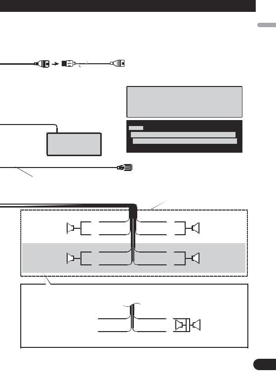
1.5 m
USB cable
Connect to separately sold USB device.
 IP-BUS cable
Multi-CD player (sold separately)
Blue/white
Connect to system control terminal of the power amp or auto-antenna relay control terminal (max. 300 mA 12 V DC).
|
|
White |
Front speaker |
+ |
|
|
≠ |
|
|
|
|
Left |
|
White/black |
|
|
Green |
Rear speaker or |
|
+ |
Subwoofer (4 Ω) |
|
≠ |
|
||
|
|
|
|
|
Green/black |
When you connect the separately sold multi-channel processor (DEQ-P7650) to this unit, do not connect anything to the speaker leads and system remote control (blue/white).
Notes:
 Change the initial setting of this unit (refer to the Operation Manual). The subwoofer output of this unit is monaural.
With a 2 speaker system, do not connect anything to the speaker leads that are not connected to speakers.
Gray
+
|
|
Front speaker |
≠ |
|
|
Gray/black |
|
Right |
Violet |
|
|
+ |
|
Rear speaker or |
≠ |
|
Subwoofer (4 Ω) |
|
||
|
|
|
Violet/black |
|
|
When using a subwoofer of 70 W (2 Ω), be sure to connect with Violet and Violet/black leads of this unit. Do not connect anything with Green and Green/black leads.
Green |
Violet |
+ |
|
Not used. |
|
|
Subwoofer (4 Ω) |
|
|
||
Green/black |
Violet/black |
|
× 2 |
≠ |
|||
|
|
|
|
Nederlands Italiano Français Deutsch Español English
4
Connecting the Units
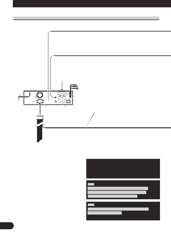
Connecting to separately sold power amp
|
|
|
|
|
Front output |
|
|
|
|
|
|
|
|
|
|
|
Rear output |
|
|
|
|
|
|
|
|
|
|
|
|
|
|
This product |
Subwoofer output |
||
Blue/white
Connect to system control terminal of the power amp or auto-antenna relay control terminal (max. 300 mA 12 V DC).
When you connect separately sold multi-channel processor (e.g. DEQ-P7650) to this unit, do not connect anything to the speaker leads and system remote control (blue/white).
Note
When you connect multi-channel processor to this unit, separately sold power amp must be connected to multi-channel processor.
Note
Change the initial setting of this product (refer to the Operation Manual).
The subwoofer output of this unit is monaural.
5

Power amp (sold separately)
Connect with RCA cables (sold separately)
Power amp (sold separately)
Power amp (sold separately)
|
|
|
|
|
|
|
|
|
|
|
System remote control |
|
|
|
|
|
|
||||
|
|
|
|
|
|
|||||
|
|
|
|
|
|
|||||
Left |
|
|
Right |
|
||||||
+ |
+ |
|
Front speaker |
|
||||||
Front speaker |
|
≠ |
≠ |
|
|
|||||
|
|
|
|
|
|
|
|
|
||
+ |
+ |
|
|
|
|
|
||||
Rear speaker |
|
≠ |
≠ |
|
Rear speaker |
|
||||
|
|
|
|
|
|
|
|
|
||
+ |
+ |
|
|
|
|
|
||||
Subwoofer |
|
|
|
|
Subwoofer |
|
||||
|
|
|
|
|||||||
|
|
|
|
≠ |
≠ |
|
|
|
|
|
Perform these connections when using the optional amplifier.
Nederlands Italiano Français Deutsch Español English
6
Connecting the Units
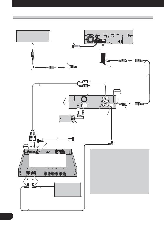
When connecting with a multi-channel processor
Rear view camera
Not used
To video output
Video input 2 (VIDEO 2/BACK CAMERA INPUT)
RCA cable (sold separately)
RCA cable
(supplied with multi- |
This product |
|
|
channel processor) |
|
AV system display (e.g. AVX-7650) (sold separately)
 1.5 m Video input
(VIDEO INPUT)
RCA cable (supplied)
15 cm
Black |
DEQ output |
Video output |
|
(VIDEO OUTPUT) |
|
|
Blue |
|
|
|
|
|
Optical cable connection |
|
Optical cable |
box (CD-DD25) |
|
(sold separately) |
|
|
(supplied with multi- |
|
|
|
|
|
channel processor) |
|
|
|
|
Blue |
Blue Black
Multi-channel processor (DEQ-P7650)
(sold separately)
Black |
Blue |
|
|
IP-BUS cable |
Multi-CD player |
|
(sold separately) |
IP-BUS cable
(supplied with multi-channel processor)
If AV system display (e.g. AVX-7650) is combined with this unit, connect the rear view camera to the AV system display. For details concerning connection methods, refer to AV system display’s instruction manual.
If AV system display is not combined with this unit, connect the rear view camera to this unit’s video input. For details concerning connection, refer to page 10.
7
Connecting and installing the optical cable connection box
 WARNING
•Avoid installing this unit in locations where the operation of safety devices such as airbags is prevented by this unit. Otherwise, there is a danger of a fatal accident.
•Avoid installing this unit in locations where the operation of the brake may be prevented. Otherwise, it may result in a traffic accident.
•Fix this unit securely with the hook and loop fastener or lock tie. If this unit is loose, it disturbs driving stability, which may result in a traffic accident.
 CAUTION
•Install this unit using only the parts supplied with this unit. If other parts are used, this unit may be damaged or could dismount itself, which leads to an accident or other problems.
•Do not install this unit near the doors where rainwater is likely to be spilled on the unit. Incursion of water into the unit may cause smoke or fire.
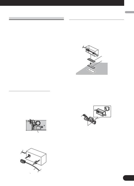
Connecting the optical cable
1.Connect the optical cable and ground lead to the main unit.
Connect the optical cable so that it does not protrude from the unit, as shown in the illustration. Fasten the ground lead to the protrusion on the back of the unit.
Installing the optical cable connection box
•When installing the optical cable connection box with the hook and loop fastener.
Install the optical cable connection box using the hook and loop fastener in the ample space of the console box.
Hook fastener
Loop fastener
•When installing the optical cable connection box with the lock tie.
Wrap the optical cable and connection box with the protection tape and fasten with the power code using the lock tie.
Wrap with the protection tape
Fasten with the lock tie
Screw
2.Connect the optical cable to the optical cable connection box.
Optical cable
Nederlands Italiano Français Deutsch Español English
8
Connecting the Units
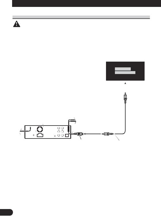
When using a display connected video outputs
WARNING
NEVER install the display in a location that enables the Driver to watch the DVD or Video CD while Driving.
Display with
RCA input jacks
To video input
This product
|
|
|
|
|
15 cm |
|
1.5 m |
||||||
|
|
|
|
|
|
||||||||
|
|
|
|
|
|
|
|
|
|
|
|
|
|
|
|
|
|
|
|
Video output |
|
RCA cable |
|||||
|
|
|
|
|
|
|
|||||||
|
|
|
|
|
|
|
|||||||
|
|
|
|
|
|
(VIDEO OUTPUT) |
|
(supplied) |
|||||
9
When connecting with a rear view camera
When this product is used with a rear view camera, it is possible to automatically switch from the video to rear view image when the gear shift is moved to REVERSE (R).
WARNING
USE INPUT ONLY FOR REVERSE OR MIRROR IMAGE REAR VIEW CAMERA. OTHER USE MAY RESULT IN INJURY OR DAMAGE.
CAUTION
•The screen image may appear reversed.
•The rear view camera function is to use this product as an aid to keep an eye on trailers, or backing into a tight parking spot. Do not use this function for entertainment purposes.
•The object in rear view may appear closer or more distant than in reality.
Español English
 CAUTION
This product |
RCA cable |
|
|
|
(sold separately) |
|
15 cm |
You must use a camera which outputs mirror reversed images.
Rear view camera
|
Video input |
To video output |
|
(VIDEO INPUT or REAR |
|
|
VIEW CAMERA INPUT) |
|
Violet/white
Of the two lead wires connected to the back lamp, connect the one in which the voltage changes when the gear shift is in the REVERSE (R) position. This connection enables the unit to sense whether the car is moving forwards or backwards.
15 cm |
Extension lead (supplied) |
8 m |
Fuse resistor
Connection method
1. Clamp the lead. |
2. Clamp firmly with |
|
needle-nosed |
|
pliers. |
Note:
It is necessary to set VIDEO IN to CAMERA in initial settings when connecting the rear view camera.
Nederlands Italiano Français Deutsch
10
Installation
Note:
•Check all connections and systems before final installation.
•Do not use unauthorized parts. The use of unauthorized parts may cause malfunctions.
•Consult with your dealer if installation requires drilling of holes or other modifications of the vehicle.
•Do not install this unit where:
—it may interfere with operation of the vehicle.
—it may cause injury to a passenger as a result of a sudden stop.
•The semiconductor laser will be damaged if it overheats. Install this unit away from hot places such as near the heater outlet.
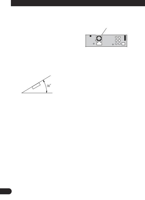
•Optimum performance is obtained when the unit is installed at an angle of less than 30°.
•The cords must not cover up the area shown in the figure below. This is necessary to allow the amplifires to radiate freely.
Do not close this area.
•When installing, to ensure proper heat dispersal when using this unit, make sure you leave ample space behind the rear panel and wrap any loose cables so they are not blocking the vents.
11
DIN Front/Rear-mount
This unit can be properly installed either from “Front” (conventional DIN Front-mount) or “Rear” (DIN Rear-mount installation, utilizing threaded screw holes at the sides of unit chassis). For details, refer to the following installation methods.
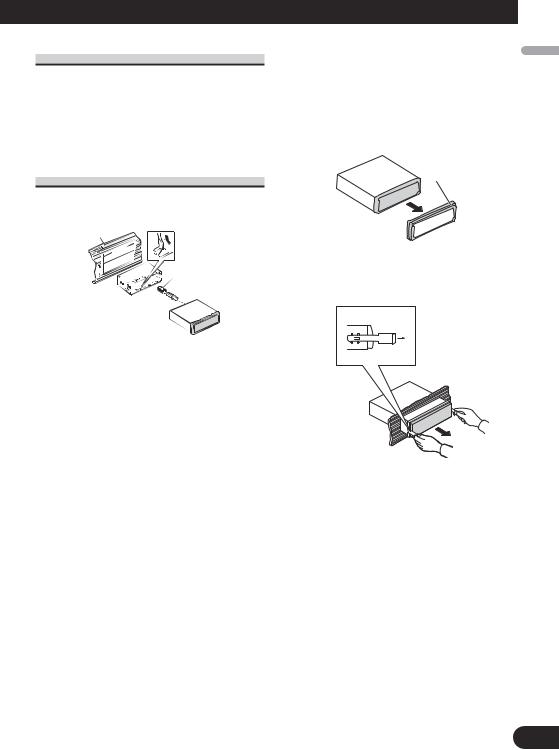
DIN Front-mount
Installation with the rubber bush
Dashboard |
Mounting sleeve |
|||
|
||||
|
|
|
||
182 |
|
|||
|
|
|
|
Rubber bush |
53 |
|
|
||
Screw
1.Insert the mounting sleeve into the dashboard.
•When installing in a shallow space, use a supplied mounting sleeve. If there is enough space behind the unit, use factory supplied mounting sleeve.
2.Secure the mounting sleeve by using a screwdriver to bend the metal tabs (90°) into place.
3.Install the unit as illustrated.
Removing the Unit
1.Extend top and bottom of the trim ring outwards to remove the trim ring. When reattaching the trim ring, push the trim ring onto the unit until it clicks. (If the trim ring is attached upside down, the trim ring will not fit properly.)
•It becomes easy to remove the trim ring if the front panel is released.
Trim ring
2.Insert the supplied extraction keys into both sides of the unit until they click into place.
3.Pull the unit out of the dashboard.
Nederlands Italiano Français Deutsch Español English
12
Installation
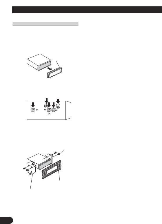
DIN Rear-mount
1.Extend top and bottom of the trim ring outwards to remove the trim ring. When reattaching the trim ring, push the trim ring onto the unit until it clicks. (If the trim ring is attached upside down, the trim ring will not fit properly.)
•It becomes easy to remove the trim ring if the front panel is released.
Trim ring
2.Determine the appropriate position where the holes on the bracket and the side of the unit match.
3.Tighten two screws on each side.
•Use either truss screws (5 mm × 8 mm) or flush surface screws (5 mm × 9 mm), depending on the shape of screw holes in the bracket.
Screw
Dashboard or Console
Factory radio mounting bracket
13
 Loading...