

PIONEER AVX-505 Service Manual

AV SYSTEM MONITOR
AVX-505 UC
Se
r
vic
e
M
a
nu
a
l
PIONEER ELECTRONIC CORPORATION 4-1, Meguro 1-Chome, Meguro-ku, Tokyo 153-8654, Japan
PIONEER ELECTRONICS SERVICE INC. P.O.Box 1760, Long Beach, CA 90801-1760 U.S.A.
PIONEER ELECTRONIC [EUROPE] N.V. Haven 1087 Keetberglaan 1, 9120 Melsele, Belgium
PIONEER ELECTRONICS ASIACENTRE PTE.LTD. 501 Orchard Road, #10-00, Lane Wheelock Place, Singapore 23880
C PIONEER ELECTRONIC CORPORATION 1998
ORDER NO.
CRT2192
CONTENTS
1. SAFETY INFORMATION ............................................2
2. EXPLODED VIEWS AND PARTS LIST.......................2
3. SCHEMATIC DIAGRAM ...........................................10
4. PCB CONNECTION DIAGRAM ................................30
5. ELECTRICAL PARTS LIST ........................................42
6. ADJUSTMENT..........................................................49
7. GENERAL INFORMATION .......................................50
7.1 IC ........................................................................50
7.2 DIAGNOSIS ........................................................51
7.2.1 DISASSEMBLY...........................................51
7.2.2 TROUBLESHOOTING FOR
LCD 5.5 MONITOR ....................................58
7.3 EXPLANATION...................................................68
7.3.1 MECHANISM DESCRIPTIONS..................68
7.3.2 BLOCK DIAGRAM......................................70
8. OPERATIONS AND SPECIFICATIONS.....................71
K-FED. APR. 1998 Printed in Japan
- Precautions on Safety for Replacement of Backlight
• High voltage is generated in the inverter when the power is supplied to the system. To avoid an electric
shock, reconfirm that the power switch is set to OFF before starting operation.
• The fluorescent tube and high-voltage parts have high temperature immediately after the power
switch of the main unit is set to OFF. To avoid burning your hand or similar accidents, wait awhile after
turning the power to OFF, then start operation.
• High voltage may be charged to the inverter immediately after the power switch of the main unit is set
to OFF. Wait awhile after turning the power to OFF, then start operation.
• In some cases, the cold cathode tube of backlight may be damaged. Take adequate caution for injury
during operation.
2
AVX-505
2. EXPLODED VIEWS AND PARTS LIST
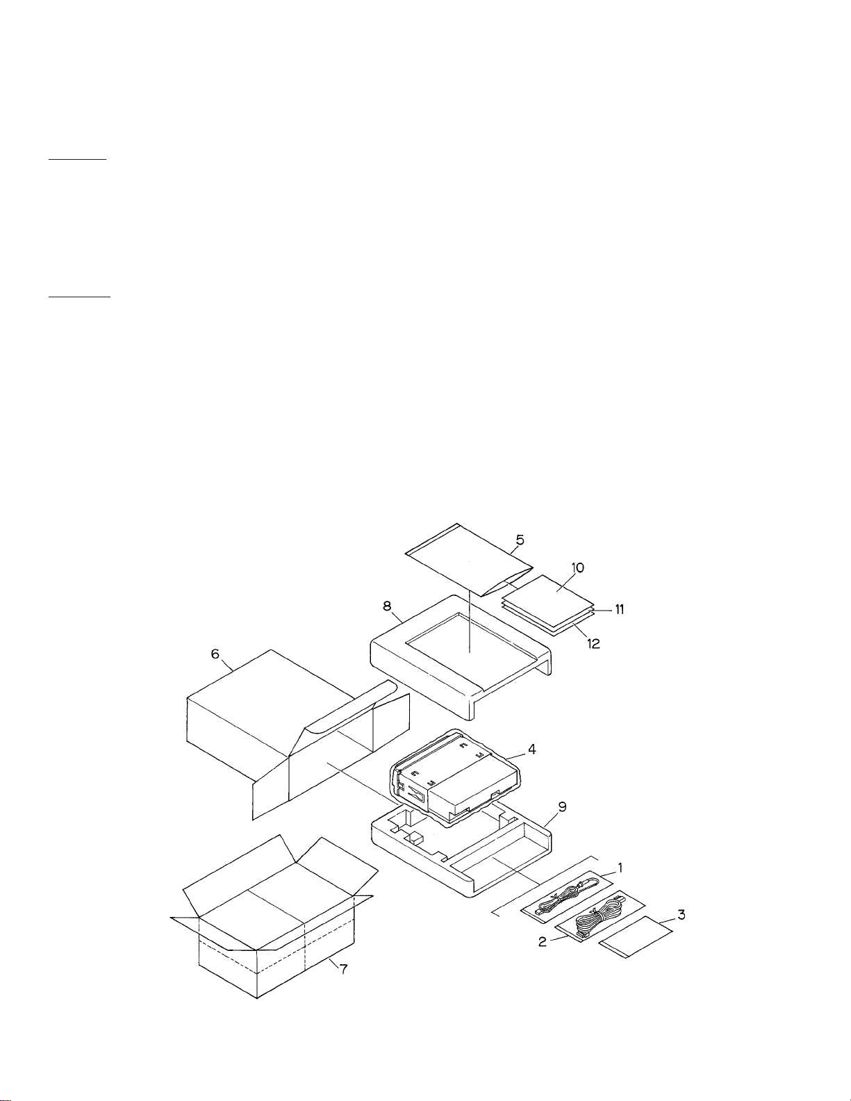
2.1 PACKING
CAUTION
This service manual is intended for qualified service technicians; it is not meant for the casual do-it-yourselfer.
Qualified technicians have the necessary test equipment and tools, and have been trained to properly and safely repair
complex products such as those covered by this manual.
Improperly performed repairs can adversely affect the safety and reliability of the product and may void the warranty.
If you are not qualified to perform the repair of this product properly and safely; you should not risk trying to do so
and refer the repair to a qualified service technician.
W
ARNING
Lead in solder used in this product is listed by the California Health and Welfare agency as a known reproductive
toxicant which may cause birth defects or other reproductive harm (California Health and Safety Code, Section
25249.5). When servicing or handling circuit boards and other components which contain lead in solder, avoid
unprotected skin contact with the solder. Also, when soldering do not inhale any smoke or fumes produced.
1. SAFETY INFORMATION

3
AVX-505
NOTE:
- Parts marked by “*”are generally unavailable because they are not in our Master Spare Parts List.
- Screws adjacent to ∇ mark on the product are used for disassembly.
- Owner's Manual
Model Part No. Language
AVX-505/UC CRD2679 English, French
1 Cord Assy CDE5626
2 Cord Assy CDE5716
3 Accessory Assy CEA2467
4 Polyethylene Bag CEG1173
5 Polyethylene Bag CEG1116
6 Carton CHG3507
7 Contain Box CHL3507
8 Protector CHP2040
9 Protector CHP2041
* 10 Card ARY1048
* 11 Warranty Card Not used
12 Owner’s Manual CRD2679
- PACKING SECTION PARTS LIST
Mark No. Description Part No.
4
AVX-505
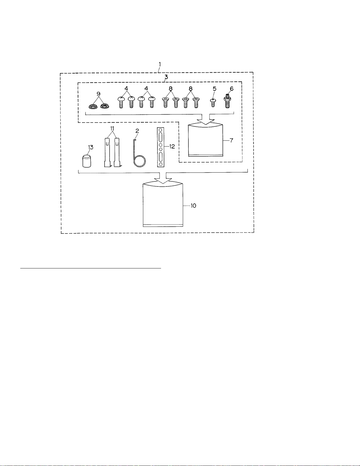
1 Accessory Assy CEA2467
2 Spring CBH-865
3 Screw Assy CEA2465
4 Screw BMZ50P060FMC
5 Screw CBA-102
6 Screw CBA1002
* 7 Polyethylene Bag CEG-127
8 Screw CMZ50P060FMC
9 Nut NF50FMC
* 10 Polyethylene Bag CEG-158
11 Handle CNC5395
12 Strap CNF-111
13 Bush CNV1009
- ACCESSORY ASSY PARTS LIST
Mark No. Description Part No.
2.2 ACCESSORY ASSY
5
AVX-505
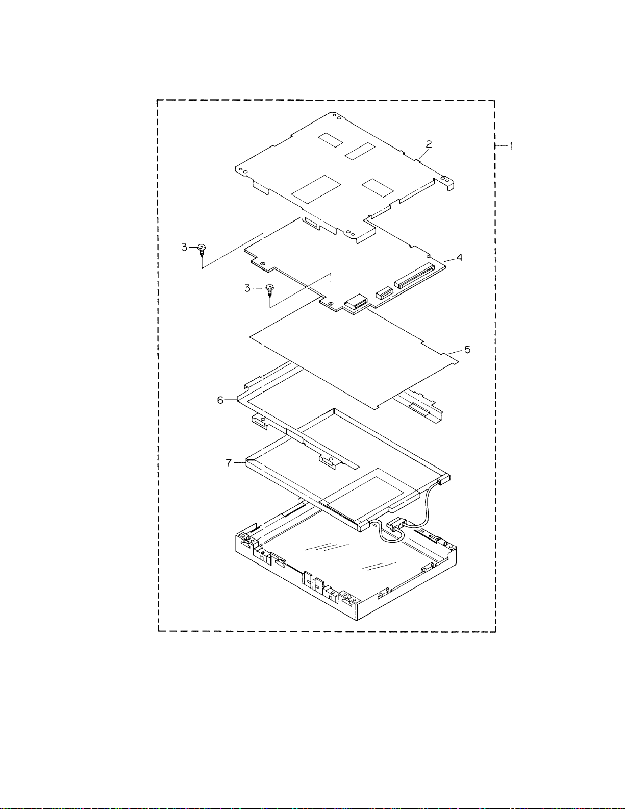
2.3 LCD 5.5 MONITOR
1 LCD 5.5 Monitor CWX2010
2 Rear Frame CZN3087
3 Screw PPZ20P040FMC
4 PCB Unit CZW3050
5 Sheet CZM3006
6 Side Frame CZN3008
7 Back Light Assy CZW3051
- LCD 5.5 MONITOR PARTS LIST
Mark No. Description Part No.
6
AVX-505
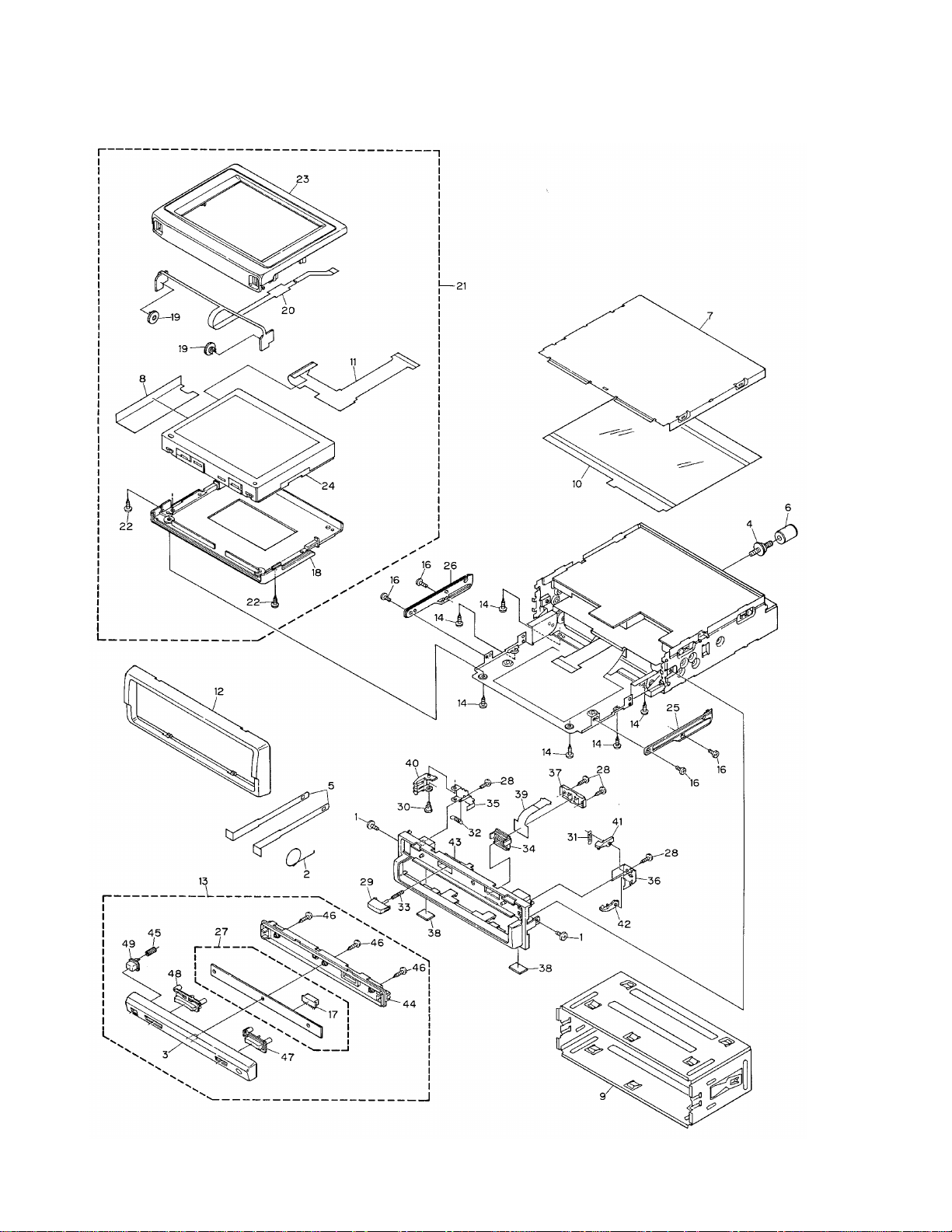
2.4 EXTERIOR (1)

7
AVX-505
1 Screw IMS20P040FZK
2 Spring CBH-865
3 Grille Unit CXB2376
4 Screw CBA1002
5 Handle CNC5395
6 Bush CNV1009
7 Case CNB2065
8 Sheet CNM5051
9 Holder CNC6798
10 Insulator CNM5743
11 PCB CNP4457
12 Panel CNS4975
13 Detach Grille Assy CXB2541
14 Screw BPZ20P080FZK
15 •••••
16 Screw CBA1378
17 Connector(CN900) CKS2733
18 Sub Grille CNS4900
19 Volume(VR951,952) CCW1019
20 PCB CNP5119
21 LCD Assy CXB2539
22 Screw BPZ20P080FZK
23 Grille Assy CXB2377
24 LCD 5.5 Monitor CWX2010
25 Rail CNS4010
26 Rail CNS4011
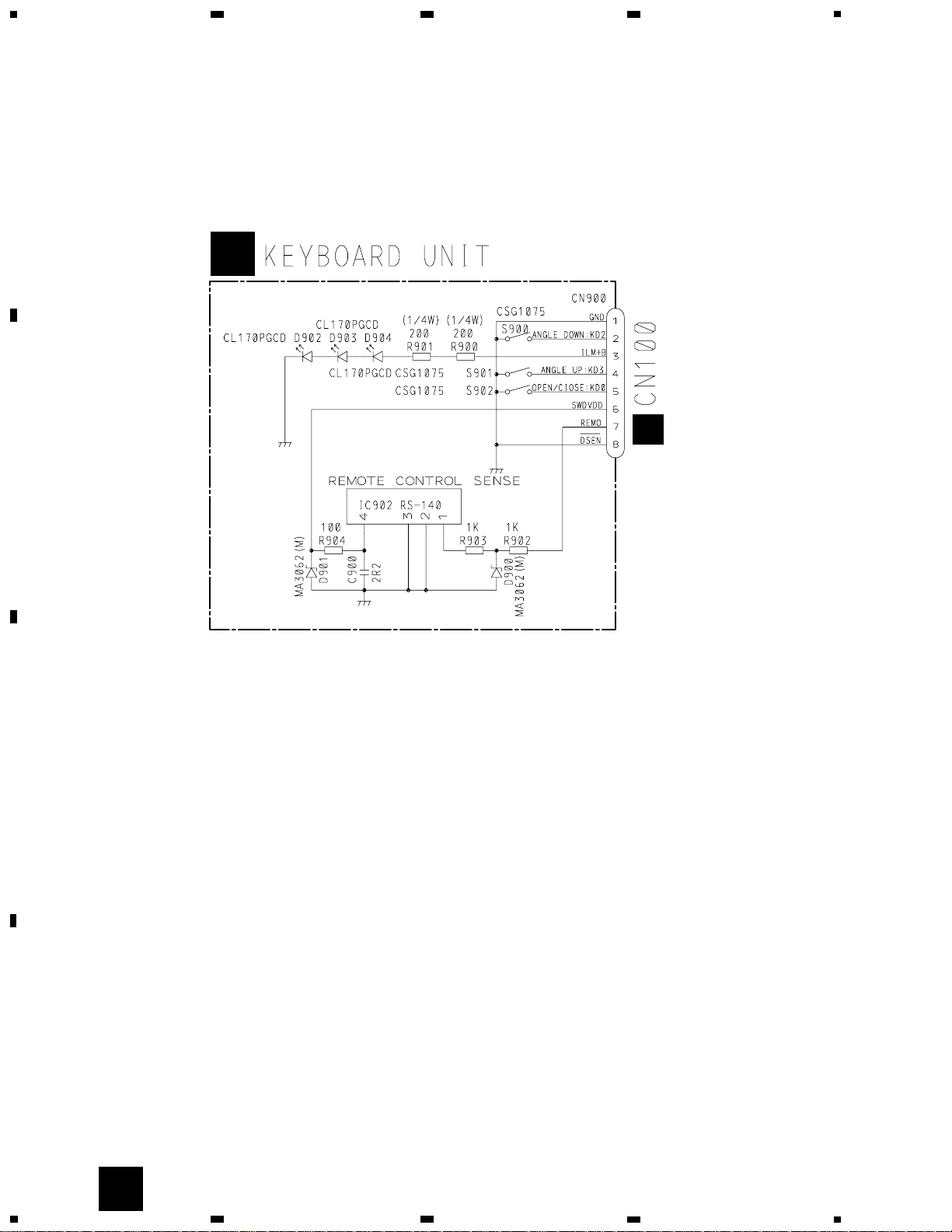
27 Keyboard Unit CWM5896
28 Screw BPZ20P080FMC
29 Button CAC5180
30 Screw CBA1215
31 Spring CBH2099
32 Spring CBH2100
33 Spring CBH2107
34 Connector CKS2780
35 Holder CNC7643
36 Holder CNC7644
37 Holder CNC7645
38 Sheet CNM5032
39 PCB CNP5168
40 Arm CNV5311
41 Arm CNV5312
42 Arm CNV5313
43 Panel Unit CXB2378
44 Cover CNS4898
45 Spring CBH2101
46 Screw BPZ20P100FZK
47 Button CAC5547
48 Button CAC5548
49 Button CAC5549
- EXTERIOR SECTION (1) PARTS LIST
Mark No. Description Part No. Mark No. Description Part No.
8
AVX-505
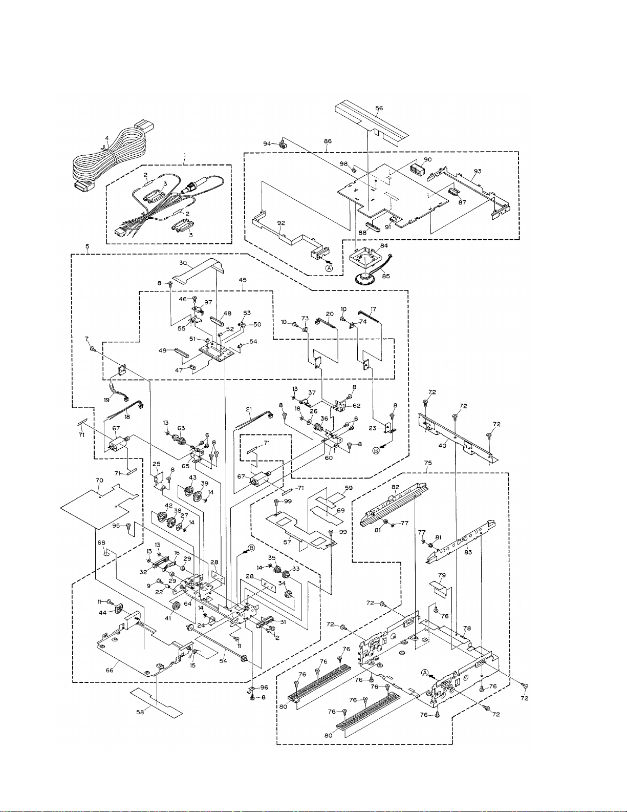
2.5 EXTERIOR (2)

9
AVX-505
1 Cord Assy CDE5626
2 Resistor RS1/2PMF102J
3 Cap CNS1472
4 Cord Assy CDE5716
5 Drive Mechanism Unit CXB2537
6 Screw BMZ20P020FMC
7 Screw CBA1077
8 Screw CBA1371
9 Screw CBA1373
10 Screw CBA1376
11 Screw CBA1378
12 Screw CBA1385
13 Washer CBF1038
14 Washer CBF1039
15 Spring CBH1922
16 Spring CBL1256
17 Connector(CN993) CDE4732
18 Connector(CN994) CDE4732
19 Connector(CN992) CDE5088
20 Connector(CN991) CDE5095
21 Connector(CN995) CDE5137
22 Shaft CLA2903
23 Bracket CNC6502
24 Arm CNC6503
25 Bracket CNC6707
26 Sheet CNM4779
27 Sheet CNM4780
28 Insulator CNM4926
29 Spacer CNM5154
30 PCB CNP4488
31 Guide CNV4569
32 Guide CNV4570
33 Gear CNV4572
34 Gear CNV4573
35 Gear CNV4574
36 Gear CNV4575
37 Arm CNV4576
38 Gear CNV4580
39 Gear CNV4581
40 Panel CNB2296
41 Gear CNV5432
42 Gear CNV5433
43 Gear CNV5434
44 Gear CNV5435
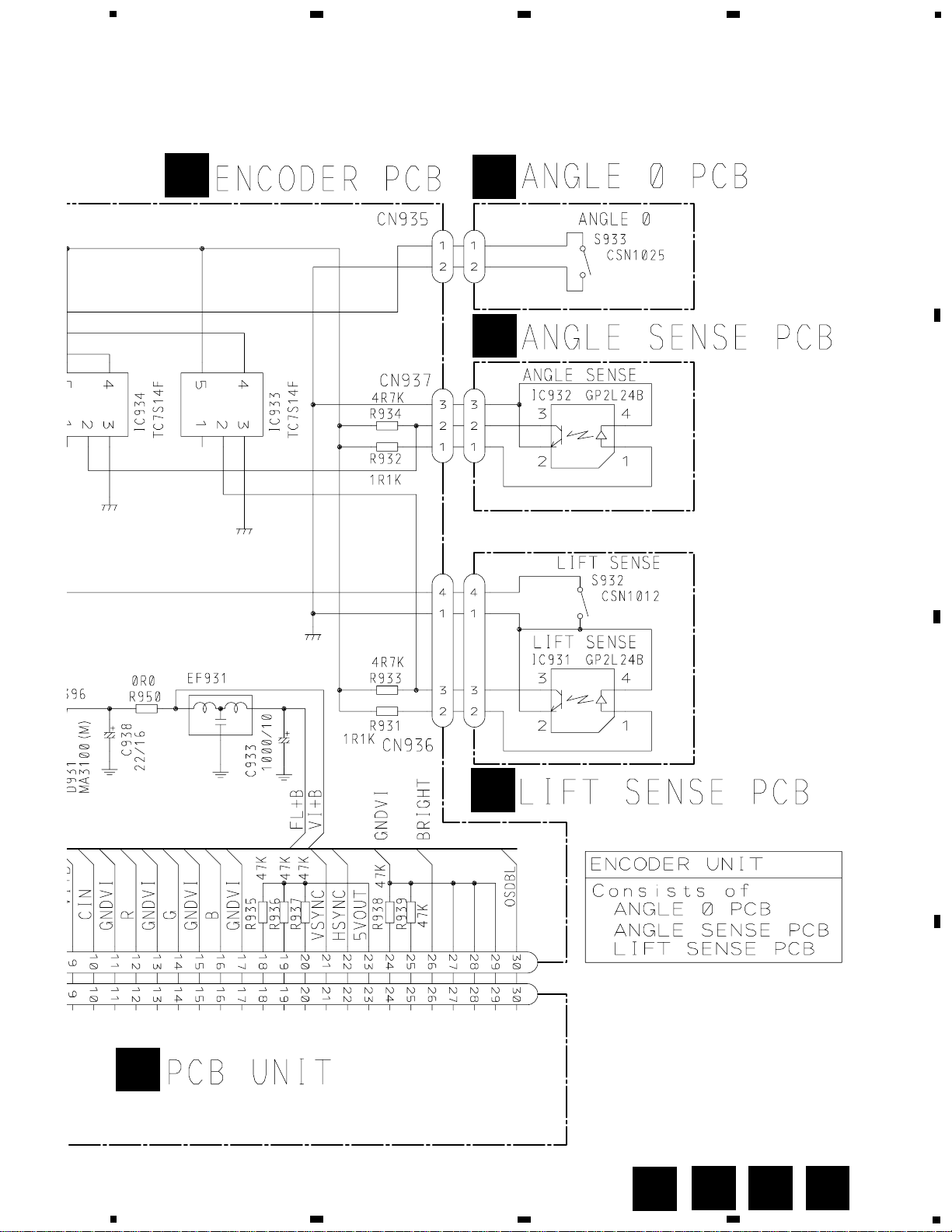
45 Encoder Unit CWM5892
46 Screw BMZ30P060FMC
47 Connector(CN938) CKS2235
48 Connector(CN932) CKS2258
49 Connector(CN939) CKS2260
50 Connector(CN933) CKS3124
51 Connector(CN934) CKS3124
52 Connector(CN935) CKS3124
53 Connector(CN937) CKS3125
54 Connector(CN936) CKS3126
55 Bracket CNC6695
56 Insulator CNM5849
57 Cover CNC6506
58 Sheet CNM4892
59 Insulator CNM5001
60 Bracket Unit CXA8990
61 Gear Unit CXA8992
62 Bracket Unit CXA9007
63 Torque Limiter Assy CXA9624
64 Frame Unit CXA9627
65 Bracket Unit CXA9679
66 Case Unit CXB2591
67 Spare Motor Unit CXX1251
68 Sheet CNM5034
69 Sheet CNM5038
70 Sheet CNM5049
71 Sheet CNM5117
72 Screw BSZ30P040FMC
73 Switch(S932) CSN1012
74 Switch(S933) CSN1025
75 Chassis Assy CXB2792
76 Screw CBA1077
77 Washer CBF1037
78 Chassis CNA2036
79 Insulator CNM4935
80 Rack CNV4567
81 Roller CNV4587
82 Rail Unit(L) CXA8988
83 Rail Unit(R) CXA8989
84 Holder CNC7718
85 Speaker CPV1041
86 Micro Computer Unit CWM5895
87 Plug(CN200) CKS-461
88 Connector(CN501) CKS2258
89 •••••
90 Connector(CN502) CKS3645
91 Connector(CN100) CKS3822
92 Holder CNC7646
93 Holder CNC7647
94 Clamper CNV1335
95 Screw BMZ20P040FMC
96 Spring CBL1277
97 Transistor(Q931) 2SD2396
98 Connector(CN500) CKS3124
99 Screw CBA1457
- EXTERIOR SECTION (2) PARTS LIST
Mark No. Description Part No. Mark No. Description Part No.
10
AVX-505
A
1
234
B
C
D
12
34
RESET
A
B
A
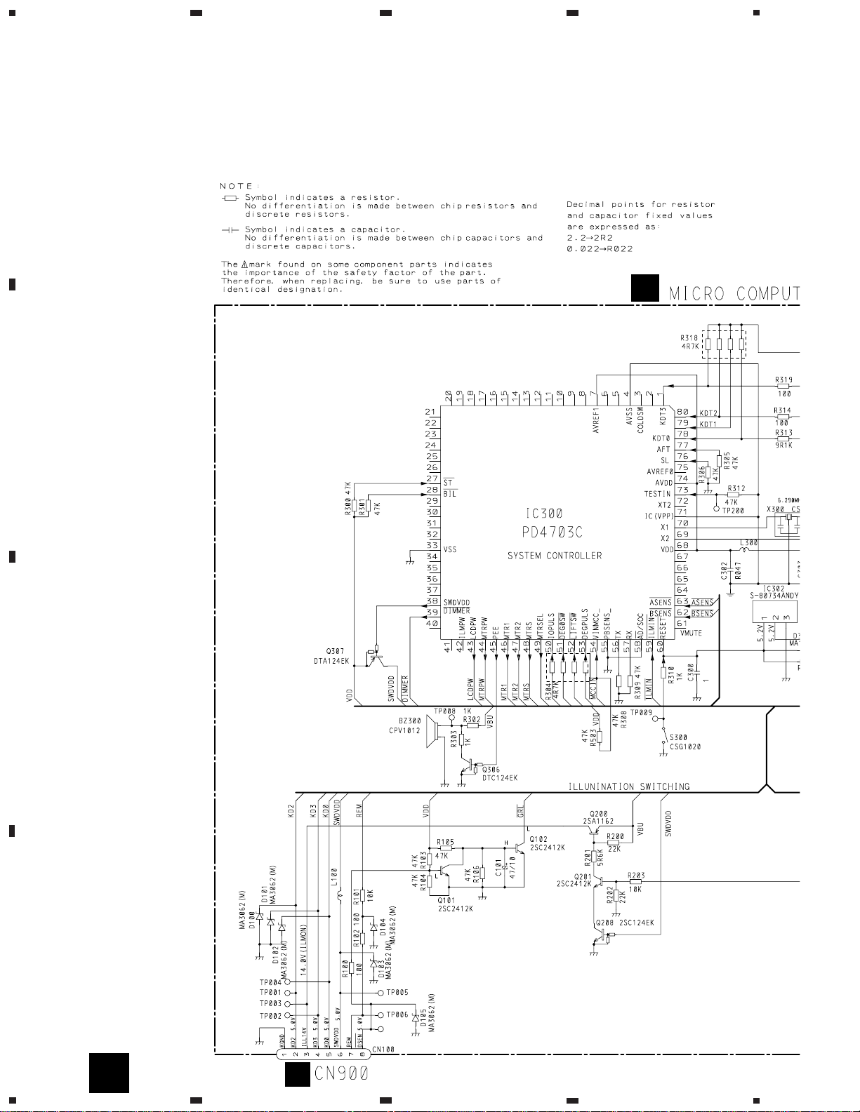
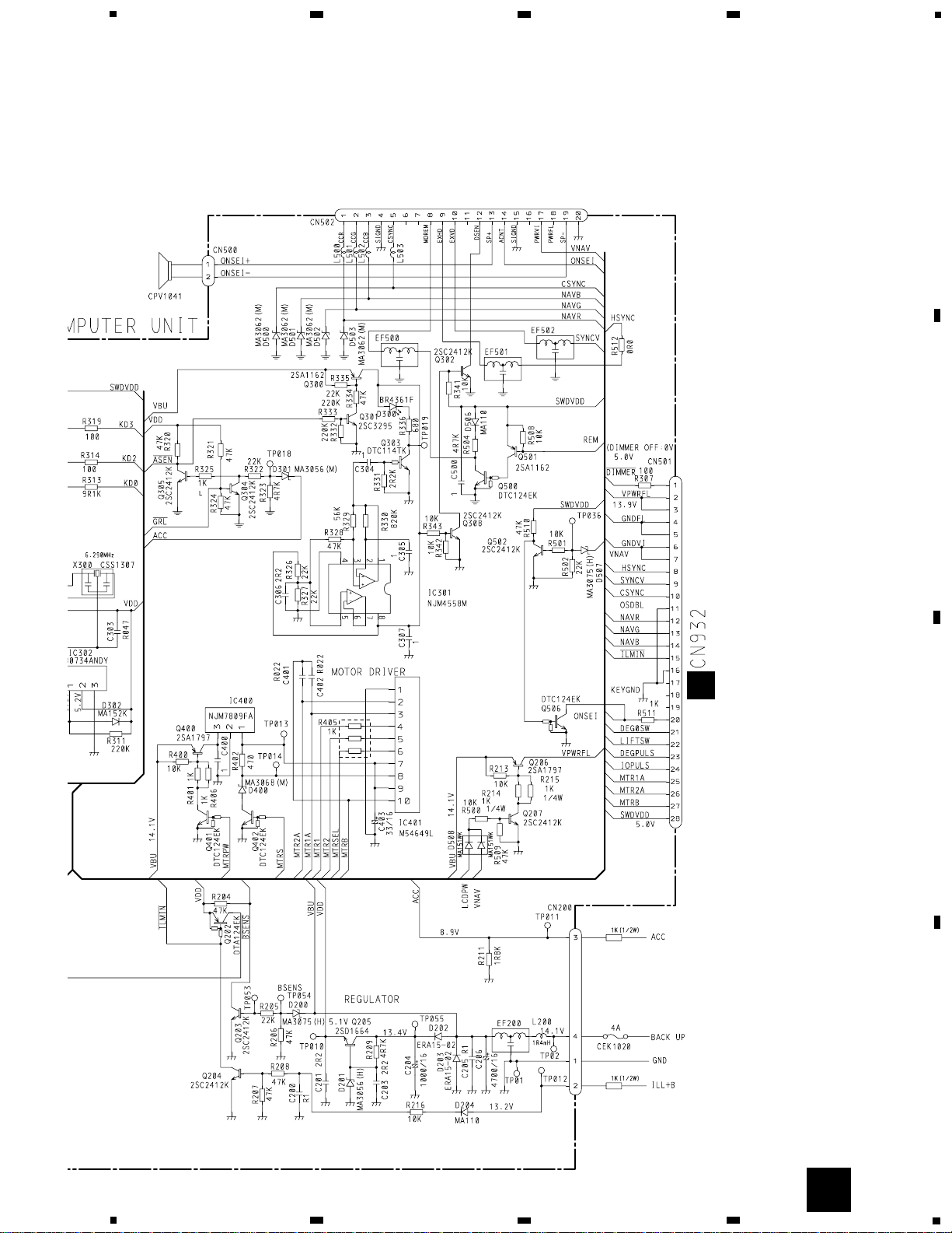
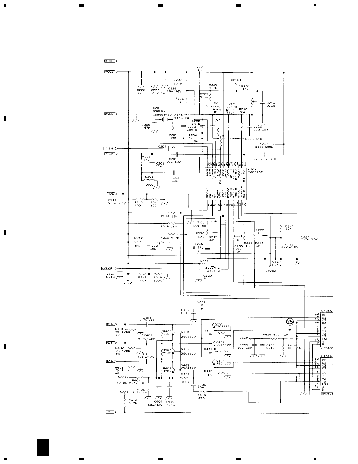
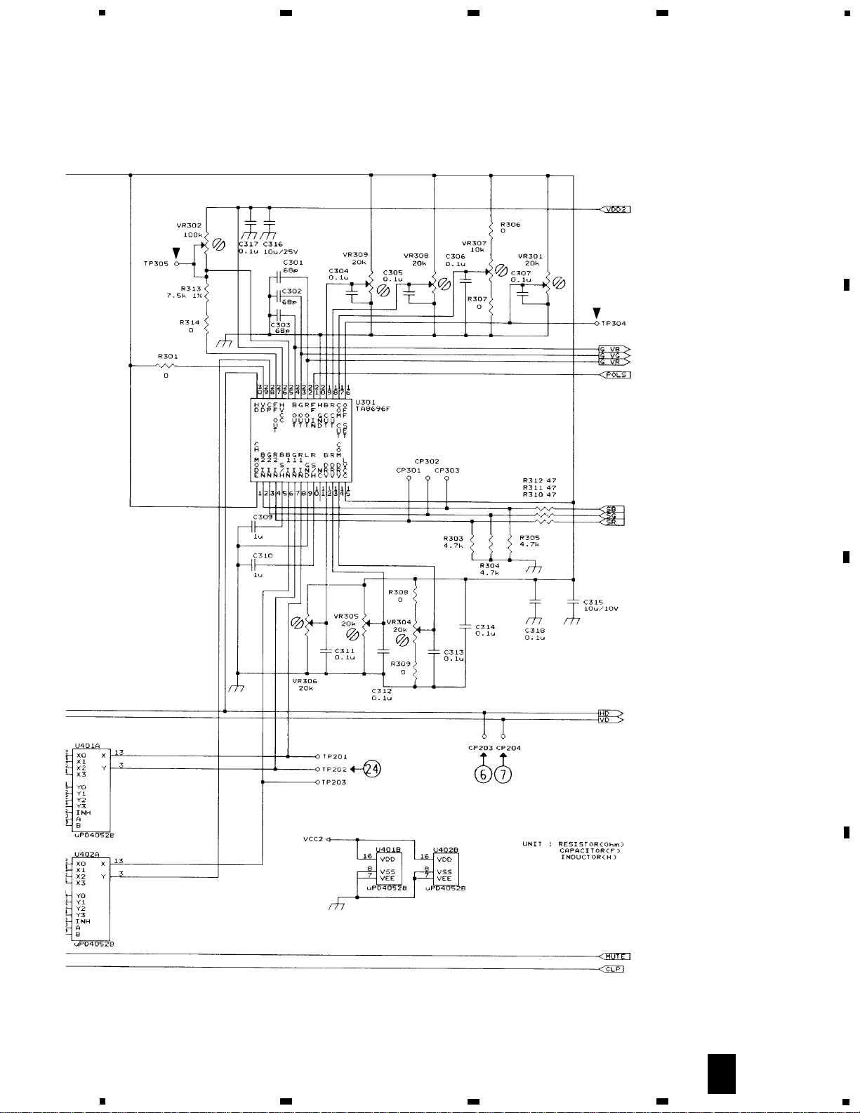
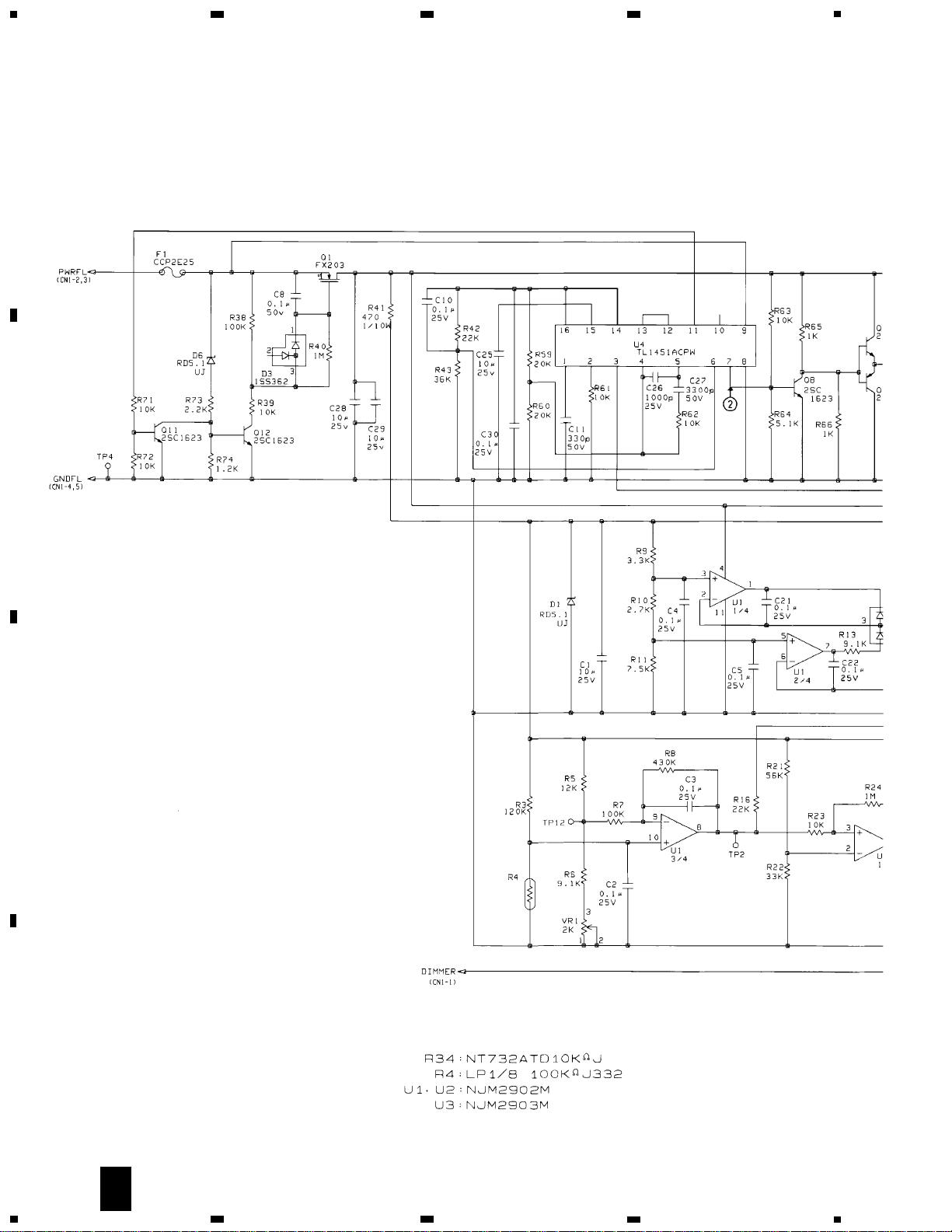
3. SCHEMATIC DIAGRAM
3.1 MICRO COMPUTER UNIT
Note: When ordering service parts, be sure to refer to “EXPLODED VIEWS AND PARTS LIST” or “ELECTRICAL PARTS
LIST”.
11
AVX-505
5
6
7
8
A
B
C
D
5
6
7
8
A
SPEAKER
C
AUDIO VISUAL MASTER UNIT
12
AVX-505
A
1
234
B
C
D
12
34
A
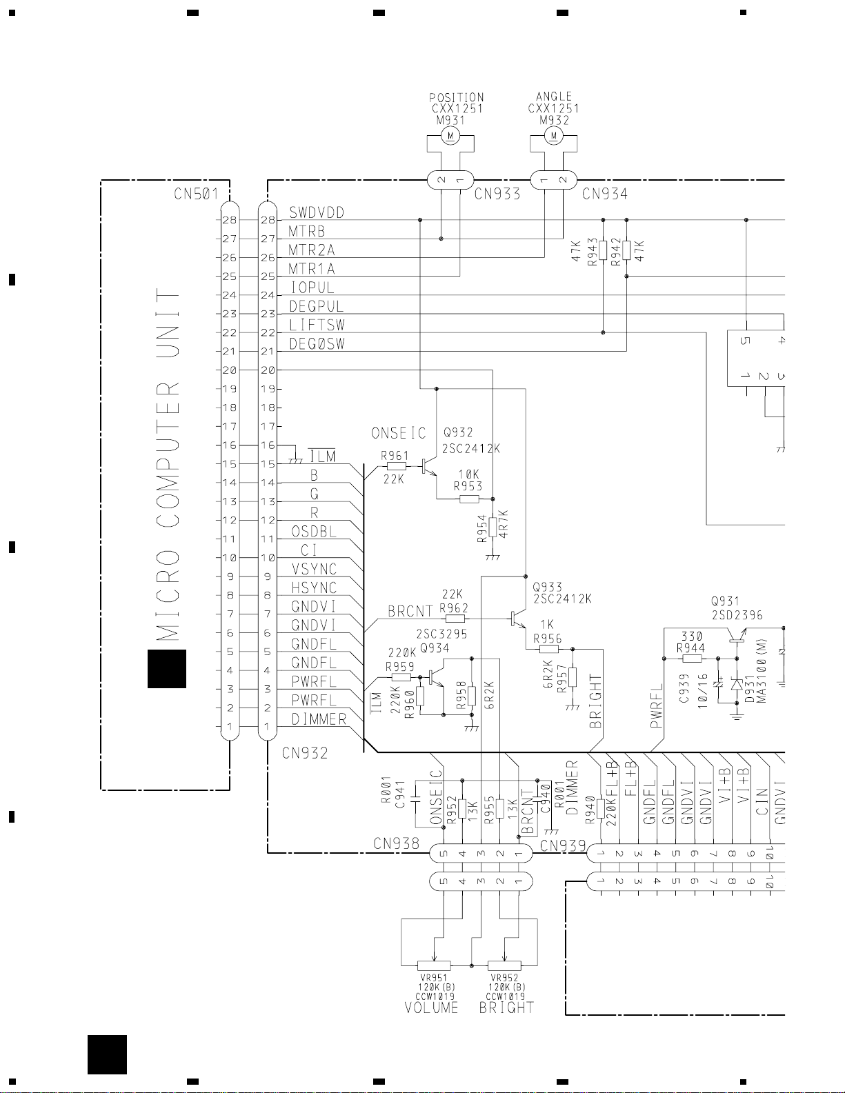
3.2 ENCODER UNIT
C
13
AVX-505
5
6
7
8
A
B
C
D
5
6
7
8
G
E
D
F
C
C
D
E
F
14
AVX-505
A
1
234
B
C
D
12
34
3.3 KEYBOARD UNIT
B
A
B

15
AVX-505
16
AVX-505
A
1
234
B
C
D
12
34
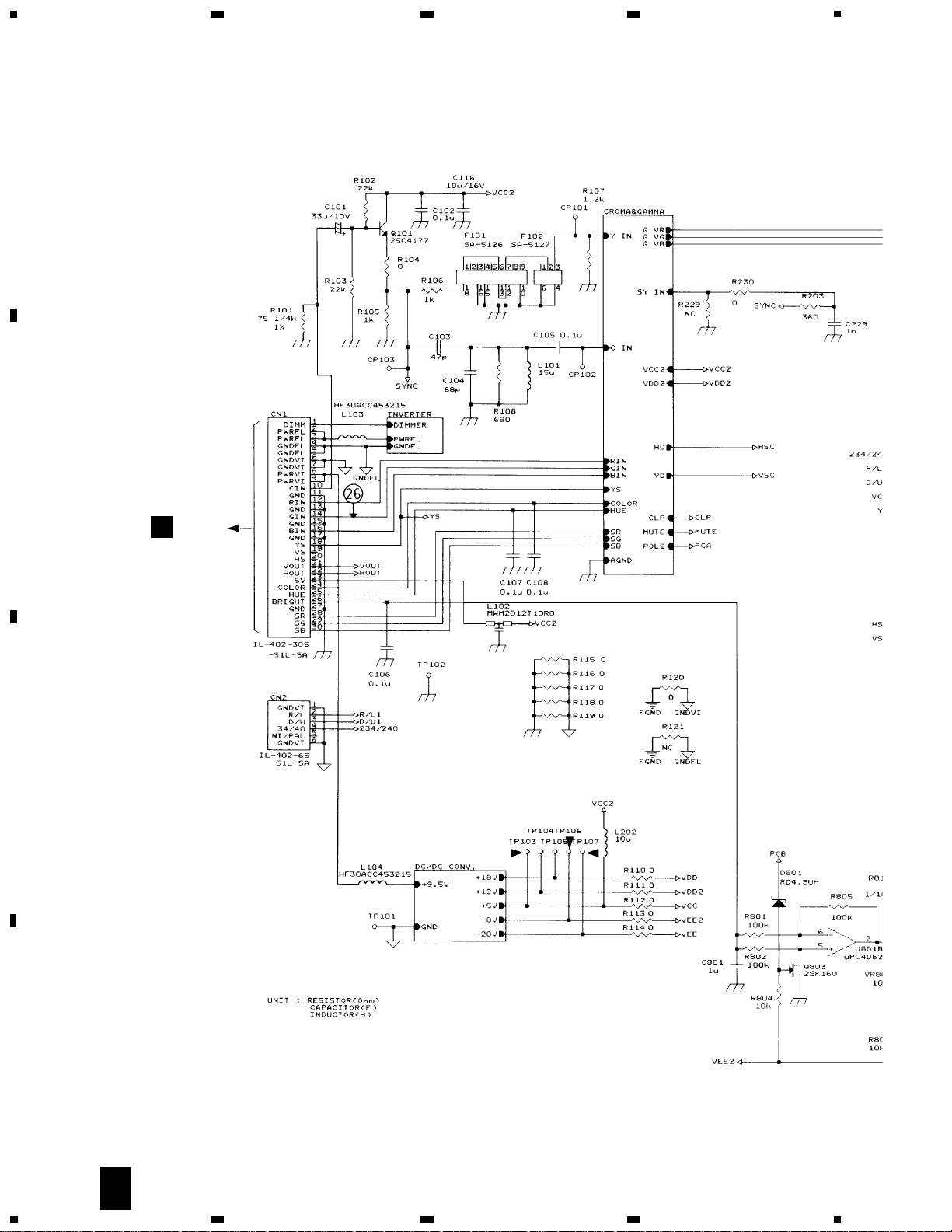
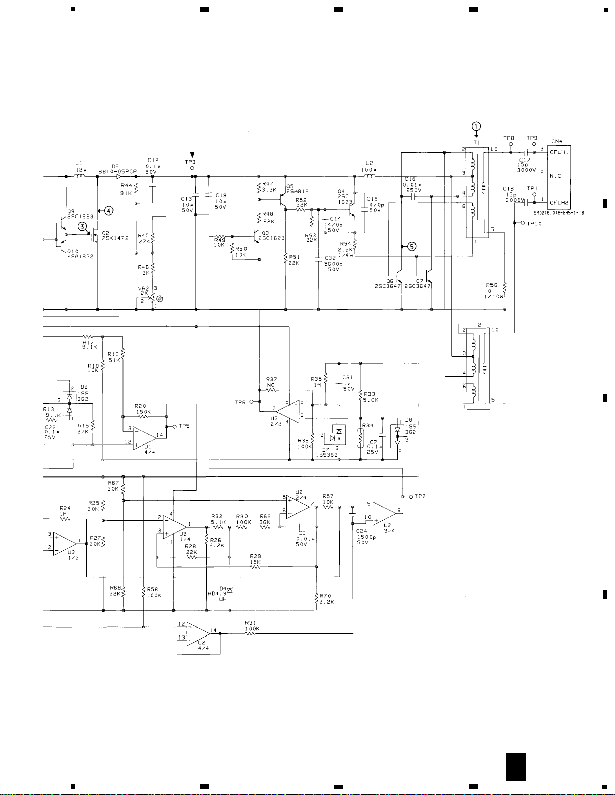
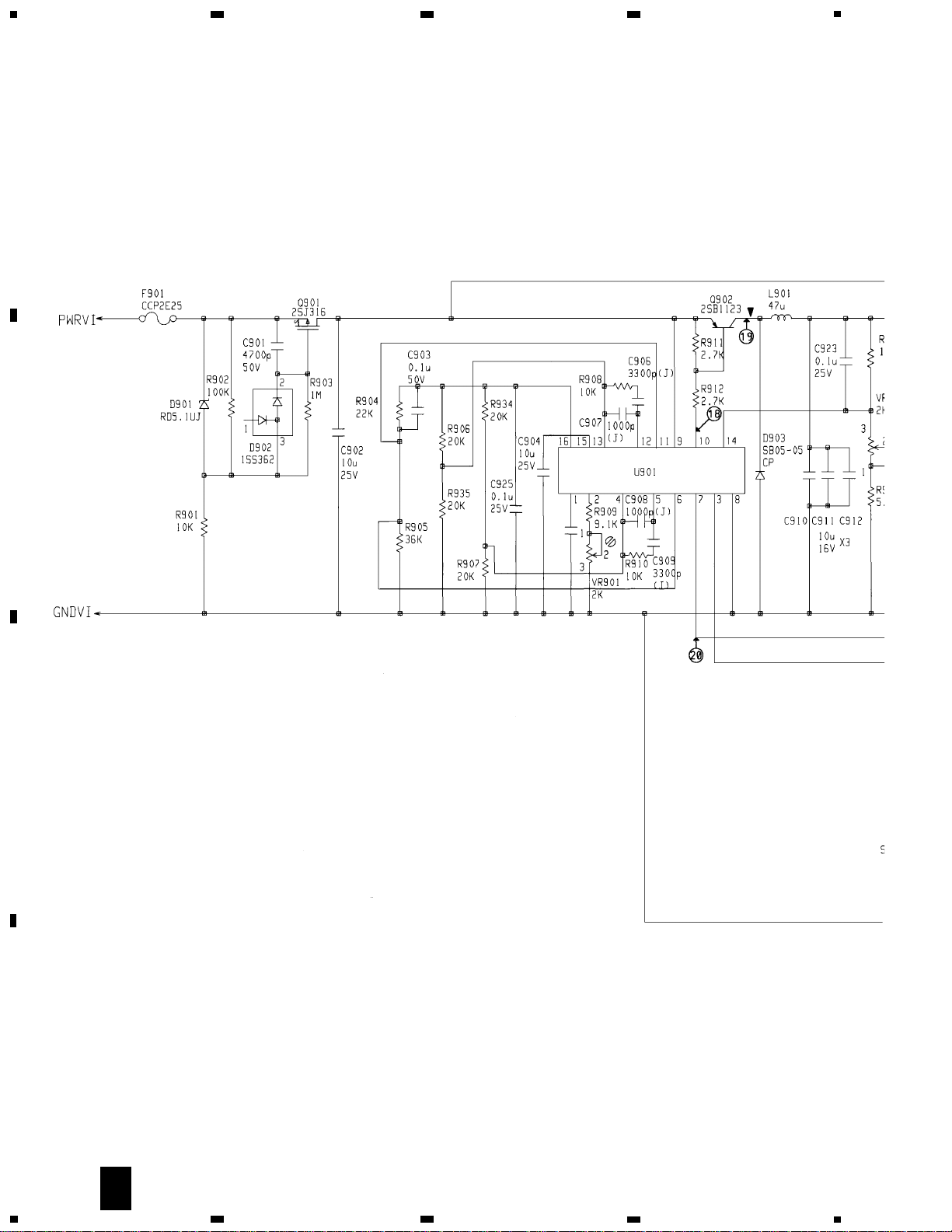
3.4 PCB UNIT (LCD 5.5 MONITOR)
- (1/5)
G
1/5
C
CN939
17
AVX-505
5
6
7
8
A
B
C
D
5
6
7
8
G
1/5
18
AVX-505
A
1
234
B
C
D
12
34
- (2/5)
G
2/5
19
AVX-505
5
6
7
8
A
B
C
D
5
6
7
8
G
2/5
20
AVX-505
A
1
234
B
C
D
12
34
- (3/5)
G
3/5
21
AVX-505
5
6
7
8
A
B
C
D
5
6
7
8
G
3/5
22
AVX-505
A
1
234
B
C
D
12
34
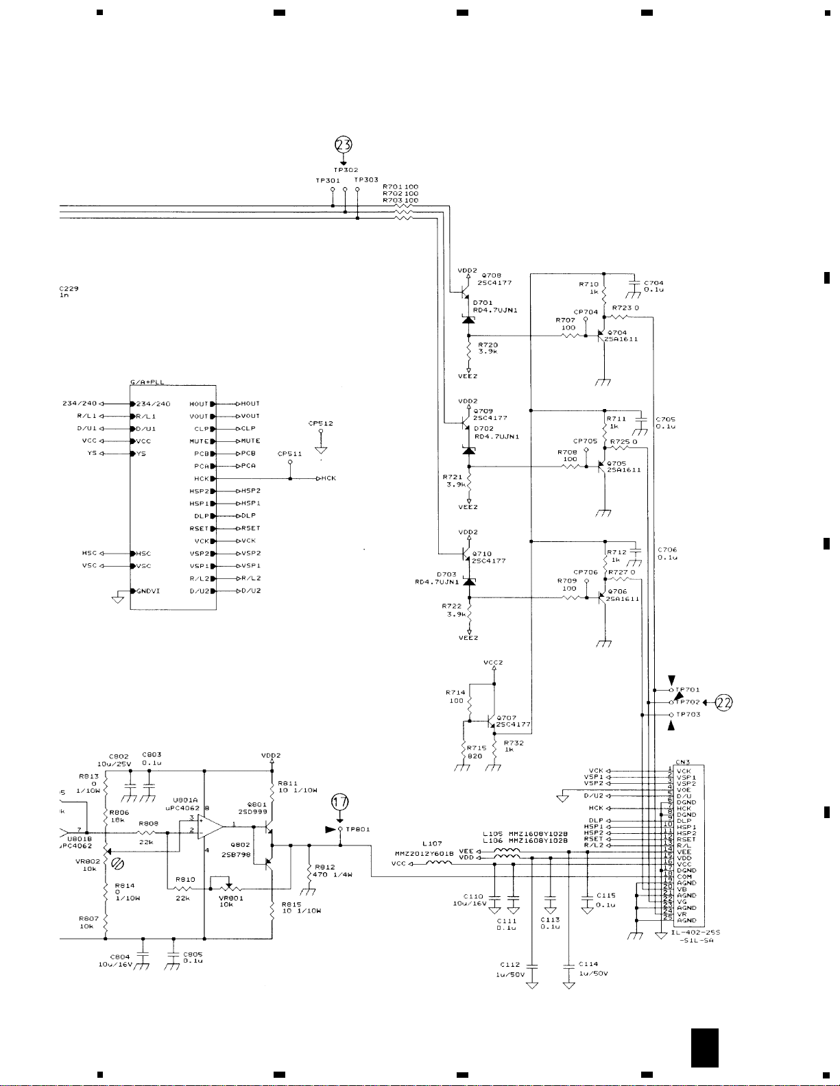
- (4/5)
G
4/5
 Loading...