


AVH-P3100DVD/XN/UC
Table of contents
 Loading...
Pioneer AVH-P3100DVD/XN/UC, AVH-P3150DVD/XN/RC, AVH-P3150DVD/XN/RD, AVH-P3150DVD/XN/RI, AVH-P3100DVD Service Manual
...
PIONEER CORPORATION 4-1, Meguro 1-chome, Meguro-ku, Tokyo 153-8654, Japan
PIONEER ELECTRONICS (USA) INC. P.O. Box 1760, Long Beach, CA 90801-1760, U.S.A.
PIONEER EUROPE NV Haven 1087, Keetberglaan 1, 9120 Melsele, Belgium
PIONEER ELECTRONICS ASIACENTRE PTE. LTD. 253 Alexandra Road, #04-01, Singapore 159936
PIONEER CORPORATION 2009
7
Q
Q
TEL 13942296513 QQ 376315150 892498299
3
DVD AV RECEIVER
6
3
1
5
1
5
0
AVH-P3100DVD/XN/UC
AVH-P3100DVD
AVH-P3150DVD
AVH-P3150DVD
AVH-P3150DVD
8
2
9
/XN/RC
/XN/RD
/XN/RI
4
9
8
2
9
ORDER NO.
CRT4258
/XN/UC
9
TEL 13942296513 QQ 376315150 892498299
TEL
13942296513
This service manual should be used together with the following manual(s):
Model No. Order No. Mech.Module Remarks
CX-3250 CRT4300 LS1 DVD Mech. Module : Circuit Descriptions, Mech. Descriptions, Disassembly
DTS and DTS Digital Out are registered trademartks and the DTS logos and Symbol are
trademarks of DTS, Inc.
Manufactured under license from Dolby Laboratories. Dolby, Pro Logic, and the double-D
symbol are trademarks of Dolby Laboratories.
For details, refer to "Important Check Points for Good Servicing".
Q
Q
3
7
6
3
1
5
1
5
0
8
9
2
4
9
8
2
9
9
w
w
w
.
xia
o
y
u
1
6
3
.
c
o
m
K-ZZZ. JAN. 2009 Printed in Japan

1234
1234
C
D
F
A
B
E
Where in a manufacturer’s service documentation, for example in circuit diagrams or lists
of components, a symbol is used to indicate that a specific component shall be replaced only
by the component specified in that documentation for safety reasons, the following symbol shall
be used:
CAUTION:
USE OF CONTROLS OR ADJUSTMENTS OR PERFORMANCE OF PROCEDURES OTHER THAN THOSE
SPECIFIED HEREIN MAY RESULT IN HAZARDOUS RADIATION EXPOSURE.
- Safety Precautions for those who Service this Unit.
When checking or adjusting the emitting power of the laser diode exercise caution in order to get safe, reliable
results.
Caution:
1. During repair or tests, minimum distance of 13 cm from the focus lens must be kept.
CAUTION
CLASS 1M INVISIBLE LASER RADIATION WHEN OPEN. DO NOT VIEW DIRECTLY WITH OPTICAL INSTRUMENTS
2. During repair or tests, do not view laser beam for 10 seconds or longer.
CAUTION
WARNING
This product contains certain electrical parts contain chemicals which are known to the State of
California to cause cancer, birth defects or other reproductive harm.
Health & Safety Code Section 25249.6 - Proposition 65
This service manual is intended for qualified service technicians; it is not meant for the casual do-it-yourselfer.
Qualified technicians have the necessary test equipment and tools, and have been trained to properly and safety repair
complex products such as those covered by this manual.
Improperly performed repairs can adversely affect the safety and reliability of the product and may void the warranty.
If you are not qualified to perform the repair of this product properly and safety, you should not risk trying to do so
and refer the repair to a qualified service technician.
SAFETY INFORMATION
Q
TEL 13942296513 QQ 376315150 892498299
Q
3
7
6
3
1
5
1
5
0
8
9
2
4
9
8
2
9
9
TEL 13942296513 QQ 376315150 892498299
TEL
13942296513
Q
Q
3
7
6
3
1
5
1
5
0
8
9
2
4
9
8
2
9
9
w
w
2
w
.
xia
o
y
u
1
6
AVH-P3100DVD/XN/UC
3
.
c
o
m
5678
56
7
8
C
D
F
A
B
E
CAUTION
Danger of explosion if battery is incorrectly replaced.
Replaced only with the same or equivalent type recommended by the manufacture.
Discord used batteries according to the manufacture's instructions.
WARNING!
The AEL (accessible emission level )of the laser power output is less than CLASS 1
but the laser component is capable of emitting radiation exceeding the limit for
CLASS 1.
A specially instructed person should do servicing operation of the apparatus.
Laser diode characteristics
Wave length:
DVD:660 nm to 670 nm
CD:780 nm to 800 nm
Focus lens on Maximum output:
CD:6.26 mW(Emitting period :9 sec.)
DVD:1.27 mW (Emitting period : unlimited)
Additional Laser Caution
Transistors Q1103 and Q1104 in PCB drive the laser diodes for DVD and CD
respectively. When Q1103 or Q1104 is shorted between their terminals,
the laser diodes for DVD or CD will radiate beam. If the top cover is removed
with no disc loaded while such short-circuit is continued, the naked eyes may
be exposed to the laser beam.
7
Q
Q
TEL 13942296513 QQ 376315150 892498299
TEL
3
13942296513
6
1
3
5
1
5
0
Q
Q
3
7
6
8
3
9
1
5
1
2
5
4
0
9
8
9
8
2
4
2
9
8
2
9
9
9
TEL 13942296513 QQ 376315150 892498299
9
w
w
w
.
xia
o
y
u
1
6
3
.
c
o
m
AVH-P3100DVD/XN/UC
3
1234
1234
C
D
F
A
B
E
[Important Check Points for Good Servicing]
In this manual, procedures that must be performed during repairs are marked with the below symbol.
Please be sure to confirm and follow these procedures.
1. Product safety
Please conform to product regulations (such as safety and radiation regulations), and maintain a safe servicing environment by
following the safety instructions described in this manual.
1 Use specified parts for repair.
Use genuine parts. Be sure to use important parts for safety.
2 Do not perform modifications without proper instructions.
Please follow the specified safety methods when modification(addition/change of parts) is required due to interferences such as
radio/TV interference and foreign noise.
3 Make sure the soldering of repaired locations is properly performed.
When you solder while repairing, please be sure that there are no cold solder and other debris.
Soldering should be finished with the proper quantity. (Refer to the example)
4 Make sure the screws are tightly fastened.
Please be sure that all screws are fastened, and that there are no loose screws.
5 Make sure each connectors are correctly inserted.
Please be sure that all connectors are inserted, and that there are no imperfect insertion.
6 Make sure the wiring cables are set to their original state.
Please replace the wiring and cables to the original state after repairs.
In addition, be sure that there are no pinched wires, etc.
7 Make sure screws and soldering scraps do not remain inside the product.
Please check that neither solder debris nor screws remain inside the product.
8 There should be no semi-broken wires, scratches, melting, etc. on the coating of the power cord.
Damaged power cords may lead to fire accidents, so please be sure that there are no damages.
If you find a damaged power cord, please exchange it with a suitable one.
9 There should be no spark traces or similar marks on the power plug.
When spark traces or similar marks are found on the power supply plug, please check the connection and advise on secure
connections and suitable usage. Please exchange the power cord if necessary.
a Safe environment should be secured during servicing.
When you perform repairs, please pay attention to static electricity, furniture, household articles, etc. in order to prevent injuries.
Please pay attention to your surroundings and repair safely.
2. Adjustments
To keep the original performance of the products, optimum adjustments and confirmation of characteristics within specification.
Adjustments should be performed in accordance with the procedures/instructions described in this manual.
4. Cleaning
For parts that require cleaning, such as optical pickups, tape deck heads, lenses and mirrors used in projection monitors, proper
cleaning should be performed to restore their performances.
3. Lubricants, Glues, and Replacement parts
Use grease and adhesives that are equal to the specified substance.
Make sure the proper amount is applied.
5. Shipping mode and Shipping screws
To protect products from damages or failures during transit, the shipping mode should be set or the shipping screws should be
installed before shipment. Please be sure to follow this method especially if it is specified in this manual.
7
Q
Q
TEL 13942296513 QQ 376315150 892498299
TEL
3
13942296513
6
3
1
5
1
5
0
Q
Q
3
7
6
8
3
9
1
5
1
2
5
4
0
9
8
9
8
2
4
2
9
8
9
2
9
9
TEL 13942296513 QQ 376315150 892498299
9
w
w
w
4
.
xia
o
y
u
1
6
AVH-P3100DVD/XN/UC
3
.
c
o
m

5678
56
7
8
C
D
F
A
B
E
CONTENTS
SAFETY INFORMATION .....................................................................................................................................2
1. SERVICE PRECAUTIONS................................................................................................................................6
1.1 SERVICE PRECAUTIONS .........................................................................................................................6
1.2 NOTES ON SOLDERING...........................................................................................................................7
7
Q
Q
TEL 13942296513 QQ 376315150 892498299
TEL
3
2. SPECIFICATIONS.............................................................................................................................................8
2.1 SPECIFICATIONS ......................................................................................................................................8
2.2 DISC/CONTENT FORMAT.......................................................................................................................11
2.3 PANEL FACILITIES...................................................................................................................................12
2.4 CONNECTION DIAGRAM........................................................................................................................16
3. BASIC ITEMS FOR SERVICE........................................................................................................................20
3.1 CHECK POINTS AFTER SERVICING .....................................................................................................20
3.2 PCB LOCATIONS .....................................................................................................................................21
3.3 JIGS LIST.................................................................................................................................................22
3.4 CLEANING ...............................................................................................................................................23
4. BLOCK DIAGRAM ..........................................................................................................................................24
4.1 OVERALL CONNECTION DIAGRAM ......................................................................................................24
4.2 BLOCK DIAGRAM....................................................................................................................................26
5. DIAGNOSIS ....................................................................................................................................................34
5.1 OPERATIONAL FLOWCHART.................................................................................................................34
5.2 INSPECTION METHOD OF PICKUP UNIT .............................................................................................35
5.3 DIAGNOSIS FLOWCHART ......................................................................................................................38
5.4 ERROR CODE LIST.................................................................................................................................65
5.5 CONNECTOR FUNCTION DESCRIPTION .............................................................................................68
6. SERVICE MODE.............................................................................................................................................69
6.1 MONITOR TEST MODE...........................................................................................................................69
6.2 DVD TEST MODE ....................................................................................................................................89
6.3 DVD TOUCH PANEL TEST MODE ..........................................................................................................93
7. DISASSEMBLY ...............................................................................................................................................94
8. EACH SETTING AND ADJUSTMENT..........................................................................................................102
8.1 DVD ADJUSTMENT ...............................................................................................................................102
8.2 MONITOR UNIT ADJUSTMENT ............................................................................................................110
8.3 PCL OUTPUT CONFIRMATION.............................................................................................................113
13942296513
9. EXPLODED VIEWS AND PARTS LIST ........................................................................................................113
9.1 PACKING ................................................................................................................................................114
9.2 EXTERIOR(1).........................................................................................................................................116
9.3 EXTERIOR(2).........................................................................................................................................118
9.4 DVD MECHANISM MODULE.................................................................................................................120
10. SCHEMATIC DIAGRAM..............................................................................................................................124
10.1 MOTHER PCB(ANALOG) ....................................................................................................................124
10.2 MOTHER PCB(TUNER) .......................................................................................................................126
10.3 MOTHER PCB(SYSTEM)(GUIDE PAGE) ............................................................................................128
10.4 MOTHER PCB(POWER SUPPLY) .......................................................................................................134
10.5 IF PCB..................................................................................................................................................136
10.6 DVD CORE UNIT(GUIDE PAGE) .........................................................................................................138
10.7 CONNECT PCB....................................................................................................................................144
10.8 KEYBOARD PCB .................................................................................................................................146
10.9 MONITOR UNIT(uCOM)(GUIDE PAGE) ..............................................................................................148
10.10 MONITOR UNIT(MONITOR)(GUIDE PAGE)......................................................................................154
10.11 WAVEFORMS.....................................................................................................................................160
11. PCB CONNECTION DIAGRAM..................................................................................................................162
11.1 MOTHER PCB....................................................................................................................
11.2 DVD CORE UNIT..................................................................................................................................166
11.3 CONNECT PCB....................................................................................................................................168
11.4 IF PCB..................................................................................................................................................170
11.5 KEYBOARD PCB .................................................................................................................................171
11.6 MONITOR UNIT ...................................................................................................................................172
12. ELECTRICAL PARTS LIST.........................................................................................................................176
6
3
1
5
1
5
0
Q
Q
3
7
6
8
3
9
1
5
1
2
5
4
0
8
9
4
2
9
8
..................162
2
9
8
2
9
9
9
TEL 13942296513 QQ 376315150 892498299
9
w
w
w
.
xia
o
y
u
1
6
3
.
AVH-P3100DVD/XN/UC
c
o
m
5
1234
1234
C
D
F
A
B
E
1. You should conform to the regulations governing the product (safety, radio and noise, and other regulations),
and should keep the safety during servicing by following the safety instructions described in this manual.
2. Be careful in handling ICs. Some ICs such as MOS type are so fragile that they can be damaged by electrostatic
induction.
3. Before disassembling the unit, be sure to turn off the power. Unplugging and plugging the connectors during
power-on mode may damage the ICs inside the unit.
4. To protect the pickup unit from electrostatic discharge during servicing, take an appropriate treatment
(shorting-solder) by referring to "the DISASSEMBLY" .
5. After replacing the pickup unit, be sure to skew adjustment.
6. During disassembly, be sure to turn the power off since an internal IC might be destroyed when a connector
is plugged or unplugged.
7. After the replacement of LS1 mecha, connect ACC and BUP, and then press RESET button.
->Some functions such as BOOK mark may not work normally.
8. Connector CN5001 in the monitor unit : When you remove the flexible from the CKS5951,
hold up the end of the flexible holddown part to remove it.
->There is a possibility of breakage of connector pin.
9. Connector CN5001 in the monitor unit : CKS5951 is a connector of both contact points.
If you insert the flexible inversely, there is a possibility of IC damaged because of unintended connection.
So please take care not to insert it inversely. If perchance you insert it inversely, you need to replace the unit.
10. The FFC styling between mother unit and DVD mecha (LS1) requires careful attention. Fold FFC to the
mecha side and style it.
11. Eject lock
Summary:DISC EJECT behavior of built-in DVD mecha is prohibited
It is for DISC antitheft from the storefront display.
With or without DISC, the behavior of pressing EJECT key during the EJECT lock is as follows.
During grille closed
Press EJECT key -> Grille is opened.
*The key is valid at the point of being pressed (BEEP). To Leave the key makes grille opened.
During grille opened
Press EJECT key -> Grille is closed.
*The key is valid at the point of being pressed (BEEP). To Leave the key makes grille opened
Remarks: [Notes] EJECT lock is not unlocked by turning ACC ON or product reset.
To unlock it, you need to operate keys as above.
For existing model (AVH-P9DVA), it is unlocked by turning ACC ON or reset.
12. Background display data is stored in IC5201. So, if you replace the IC, user photo data will be lost.
13. If the gasket (CNN2782) on the FM/AM tuner unit was damaged or lost, then the reception
sensitivity would be poor. So, replace it with the new one.
14. When the DVD mechanism is connected with the mother unit for the first time, initial data is written.
So, do not turn the power off for 10 seconds.
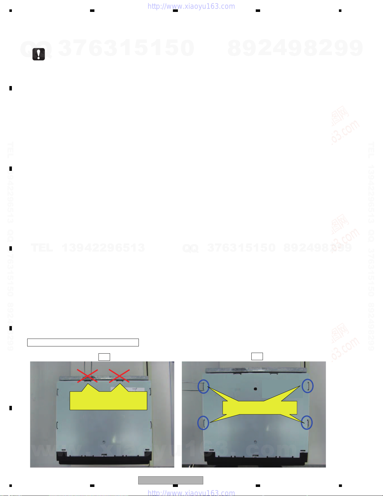
NOTE: When you remove the top case
NG
OK
Use these holes to remove the top
case.
Don't put tweezers or something
into these holes to remove the top
case
1. SERVICE PRECAUTIONS
1.1 SERVICE PRECAUTIONS
Q
TEL 13942296513 QQ 376315150 892498299
Q
TEL
7
3
13942296513
6
3
1
5
1
5
0
Q
Q
3
7
6
8
3
9
1
5
1
2
5
4
0
9
8
9
8
2
4
2
9
8
9
2
9
9
TEL 13942296513 QQ 376315150 892498299
9
w
6
w
w
.
xia
o
y
u
1
6
AVH-P3100DVD/XN/UC
3
.
c
o
m

5678
56
7
8
C
D
F
A
B
E
For environmental protection, lead-free solder is used on the printed circuit boards mounted in this unit.
Be sure to use lead-free solder and a soldering iron that can meet specifications for use with lead-free solders for repairs
accompanied by reworking of soldering.
Compared with conventional eutectic solders, lead-free solders have higher melting points, by approximately 40 C.
Therefore, for lead-free soldering, the tip temperature of a soldering iron must be set to around 373 C in general, although
the temperature depends on the heat capacity of the PC board on which reworking is required and the weight of the tip of
the soldering iron.
Compared with eutectic solders, lead-free solders have higher bond strengths but slower wetting times and higher melting
temperatures (hard to melt/easy to harden).
The following lead-free solders are available as service parts:
Parts numbers of lead-free solder:
GYP1006 1.0 in dia.
GYP1007 0.6 in dia.
GYP1008 0.3 in dia.
1.2 NOTES ON SOLDERING
7
Q
Q
TEL 13942296513 QQ 376315150 892498299
3
6
3
1
5
1
5
0
8
9
2
4
9
8
2
9
9
TEL 13942296513 QQ 376315150 892498299
TEL
13942296513
Q
Q
3
7
6
3
1
5
1
5
0
8
9
2
4
9
8
2
9
9
w
w
w
.
xia
o
y
u
1
6
3
.
AVH-P3100DVD/XN/UC
c
o
m
7

1234
1234
C
D
F
A
B
E
General
Power source..........................14.4 V DC (10.8 V to 15.1 V
allowable)
Grounding system................ Negative type
Max. current consumption
...............................................10.0 A
Dimensions (W × H × D):
DIN
Chassis.................. 178 mm × 100 mm × 165
mm
(7 in. × 3-7/8 in. × 6-1/2 in.)
Nose........................ 171 mm × 97 mm × 8 mm
(6-3/4 in.× 3-7/8 in.× 3/8 in.)
Weight ..................................... 1.7 kg (3.7 lbs)
Display
Screen size/aspect ratio...... 5.8 inch wide/16:9
(effective display area: 128.1
×71mm)
Pixels ....................................... 336 960 (1 440 × 234)
Display method ..................... TFT active matrix, transmis-
sive type
Color system.......................... NTSC
Durable temperature range (power off)
.............................................. -20 °C to +80 °C
Audio
Maximum power output ...... 50 W × 4
50 W × 2/4
+ 70 W × 1/2
(for subwoofer)
Continuous power output .. 22 W × 4 (1 kHz, 5% THD, 4
load, both channels dri-
ven)
Load impedance ................... 4
to 8 ×4
4
to 8 ×2+2 ×1
Preout max output level ...... 4.0 V
Equalizer (3-Band Parametric Equalizer):
Low
Frequency.............. 40/80/100/160 Hz
Q Factor .................0.35/0.59/0.95/1.15 (+6 dB
when boosted)
Gain ......................... ±12 dB
Mid
Frequency.............. 200/500/1k/2k Hz
Q Factor .................0.35/0.59/0.95/1.15 (+6 dB
when boosted)
Gain ......................... ±12 dB
High
Frequency.............. 3.15k/8k/10k/12.5k Hz
Q Factor .................0.35/0.59/0.95/1.15 (+6 dB
when boosted)
Gain ......................... ±12 dB
HPF:
Frequency.......................50/63/80/100/125 Hz
Slope................................–12 dB/oct
Subwoofer (mono):
Frequency.......................50/63/80/100/125 Hz
Slope................................–18 dB/oct
Gain ................................. +6 dB to – 24 dB
Phase ............................. Normal/Reverse
Bass boost:
Gain ................................. +12 dB to 0 dB
DVD Player
System .................................... DVD video, Video CD, CD,
WMA, MP3, AAC, DivX,
JPEG system
Usable discs .......................... DVD video, Video CD, CD,
CD-R/RW, DVD-R/RW/RDL
Region number .................... 1
Frequency response............ 5 Hz to 44 000 Hz(with DVD,
at sampling frequency 96
kHz)
Signal-to-noise ratio............ 96 dB (1 kHz) (IHF-A net-
work) (RCA level)
Output level:
Video............................... 1.0 Vp-p/75
(±0.2 V)
Number of channels ............ 2 (stereo)
MP3 decoding format ..........MPEG-1 & 2 Audio Layer 3
WMA decoding format ....... Ver. 7, 7.1, 8, 9, 10, 11 (2ch
audio)
(Windows Media Player)
AAC decoding format........... MPEG-4 AAC (iTunes en-
coded only) (.m4a)
(Ver. 8.0 and earlier)
DivX decoding format...........Home Theater Ver. 3, 4, 5.2,
6 (.avi, .divx)
USB
USB standard specification
.............................................. USB 1.1, USB 2.0 full speed
Maximum current supply ... 500 mA
USB Class.............................. MSC (Mass Storage Class)
File system............................. FAT16, FAT32
MP3 decoding format ..........MPEG-1 & 2 Audio Layer 3
WMA decoding format ....... Ver. 7, 7.1, 8, 9, 10, 11 (2ch
audio)
(Windows Media Player)
AAC decoding format.......... MPEG-4 AAC (iTunes en-
coded only) (.m4a)
(Ver. 8.0 and earlier)
FM tuner
Frequency range................... 87.9 MHz to 107.9 MHz
Usable sensitivity.................. 9 dB f (0.8 μV/75
, mono,
S/N: 30 dB)
Backup current ....................... 2 mA or less
AVH-P3100DVD/XN/UC
2. SPECIFICATIONS
2.1 SPECIFICATIONS
7
Q
Q
TEL 13942296513 QQ 376315150 892498299
TEL
w
8
3
13942296513
w
w
6
.
xia
3
1
5
o
AVH-P3100DVD/XN/UC
1
5
0
Q
Q
y
u
1
6
3
2
9
8
3
6
7
3
.
1
1
5
c
0
5
o
4
8
m
9
9
8
2
4
2
9
8
9
2
9
9
TEL 13942296513 QQ 376315150 892498299
9
5678
56
7
8
C
D
F
A
B
E
7
Q
Q
TEL 13942296513 QQ 376315150 892498299
3
Signal-to-noise ratio............. 72 dB (IHF-A network)
AM tuner
Frequency range................... 530 kHz to 1 710 kHz (10
Usable sensitivity.................. 25 μV (S/N: 20 dB)
Signal-to-noise ratio............. 62 dB (IHF-A network)
CEA2006 Specifications
Power output ......................... 14 W RMS × 4 Channels (4
S/N ratio .................................. 91 dBA (reference: 1 W into
Specifications and the design are subject to modifications without notice due to improvements.
6
Note
3
1
5
kHz)
and 1 % THD+N)
4
)
1
5
0
8
9
2
4
9
8
2
9
9
TEL 13942296513 QQ 376315150 892498299
TEL
13942296513
Q
Q
3
7
6
3
1
5
1
5
0
8
9
2
4
9
8
2
9
9
w
w
w
.
xia
o
y
u
1
6
3
.
AVH-P3100DVD/XN/UC
c
o
m
9
1234
1234
C
D
F
A
B
E
Dimensions (W × H × D):
DIN
Chassis.................. 178 mm × 100 mm × 165
mm
Nose....................... 171 mm × 97 mm × 8 mm
Weight .................................... 1.7 kg
Display
Screen size/aspect ratio..... 5.8 inch wide/16:9
(effective display area: 128.1
×71mm)
Pixels ...................................... 336 960 (1 440 × 234)
Display method .................... TFT active matrix, transmis-
sive type
Color system.......................... NTSC/PAL/PAL-M/SECAM
compatible
Durable temperature range (power off)
............................................... -20 °C to +80 °C
Audio
Maximum power output ...... 50 W × 4
50 W × 2/4
+ 70 W × 1/2
(for subwoofer)
Continuous power output .. 22 W × 4 (1 kHz, 5% THD, 4
load, both channels dri-
ven)
Load impedance ................... 4
to 8 ×4
4
to 8 ×2+2 ×1
Preout max output level ...... 4.0 V
Equalizer (3-Band Parametric Equalizer):
Low
Frequency.............. 40/80/100/160 Hz
Q Factor .................0.35/0.59/0.95/1.15 (+6 dB
when boosted)
Gain ........................ ±12 dB
Mid
Frequency.............. 200/500/1k/2k Hz
Q Factor .................0.35/0.59/0.95/1.15 (+6 dB
when boosted)
Gain ........................ ±12 dB
High
Frequency.............. 3.15k/8k/10k/12.5k Hz
Q Factor .................0.35/0.59/0.95/1.15 (+6 dB
when boosted)
Gain ........................ ±12 dB
HPF:
Frequency.......................50/63/80/100/125 Hz
Slope................................–12 dB/oct
Subwoofer (mono):
Frequency.......................50/63/80/100/125 Hz
Slope................................–18 dB/oct
Gain .................................. +6 dB to – 24 dB
Phase ..............................Normal/Reverse
Bass boost:
Gain .................................. +12 dB to 0 dB
DVD Player
System .................................... DVD video, DVD-VR, Video
CD, CD, WMA, MP3, AAC,
DivX, JPEG system
Usable discs .......................... DVD video, Video CD, CD,
CD-R/RW, DVD-R/RW/RDL
Region number:
for Middle East Asian and South African models
.................................... 2
for Southeast Asian models
.................................... 3
for South American and Oceanian models
.................................... 4
Frequency response............ 5 Hz to 44 000 Hz(with DVD,
at sampling frequency 96
kHz)
Signal-to-noise ratio............. 96 dB (1kHz) (IEC-A net-
work) (RCA level)
Output level:
Video............................... 1.0 Vp-p/75
(±0.2 V)
Number of channels ............ 2 (stereo)
MP3 decoding format ..........MPEG-1 & 2 Audio Layer 3
WMA decoding format ........ Ver. 7,7.1, 8, 9, 10, 11 (2ch
audio)
(Windows Media Player)
AAC decoding format........... MPEG-4 AAC (iTunes en-
coded only) (.m4a)
(Ver. 8.0 and earlier)
DivX decoding format...........Home Theater Ver. 3, 4, 5.2,
6 (.avi, .divx)
USB
USB standard specification
............................................... USB 1.1, USB 2.0 full speed
Maximum current supply .... 500 mA
USB Class............................... MSC(Mass Storage Class)
File system............................. FAT16, FAT32
MP3 decoding format ..........MPEG-1 & 2 Audio Layer 3
WMA decoding format ........ Ver. 7,7.1, 8, 9, 10, 11 (2ch
audio)
(Windows Media Player)
General
Power source..........................14.4 V DC (12.0 V to 14.4 V
allowable)
Grounding system................. Negative type
Max. current consumption
................................................10.0 A
Backup current ........................2 mA or less
AVH-P3150DVD/XN/RC, AVH-P3150DVD/XN/RD, AVH-P3150DVD/XN/RI
7
Q
Q
TEL 13942296513 QQ 376315150 892498299
TEL
w
3
13942296513
w
w
6
.
xia
3
1
5
o
1
5
0
Q
Q
y
u
1
6
3
6
7
3
4
2
9
8
8
0
5
1
5
1
3
.
c
o
m
9
9
8
2
4
2
9
8
9
2
9
9
TEL 13942296513 QQ 376315150 892498299
9
10
AVH-P3100DVD/XN/UC
5678
56
7
8
C
D
F
A
B
E
AAC decoding format.......... MPEG-4 AAC (iTunes en-
coded only) (.m4a)
(Ver. 8.0 and earlier)
FM tuner
Frequency range....................87.5 MHz to 108.0 MHz
Usable sensitivity................... 9 dB f (0.8 μV/75
, mono,
S/N: 30 dB)
Signal-to-noise ratio............. 72 dB (IEC -A network)
AM tuner
Frequency range................... 531 kHz to 1 602 kHz (9 kHz)
530 kHz to 1 640 kHz (10
kHz)
Usable sensitivity.................. 25 μV (S/N: 20 dB)
Signal-to-noise ratio............. 62 dB (IEC -A network)
Infrared remote control
Wavelength............................. 945 nm
Output ......................................typ; 10 mw/sr per Infrared
LED
Note
Specifications and the design are subject to modifications without notice due to improvements.
is a trademark of DVD Format/Logo Licensing Corporation.
AVH-P3100DVD/XN/UC
7
Q
Q
TEL 13942296513 QQ 376315150 892498299
3
6
3
1
5
1
5
0
8
9
2
4
9
8
2
9
9
TEL 13942296513 QQ 376315150 892498299
TEL
13942296513
2.2 DISC/CONTENT FORMAT
Q
Q
3
7
6
3
1
5
1
5
0
8
9
2
4
9
8
2
9
9
w
w
w
.
xia
o
y
u
1
6
AVH-P3100DVD/XN/UC
3
.
c
o
m
11
1234
1234
C
D
F
A
B
E
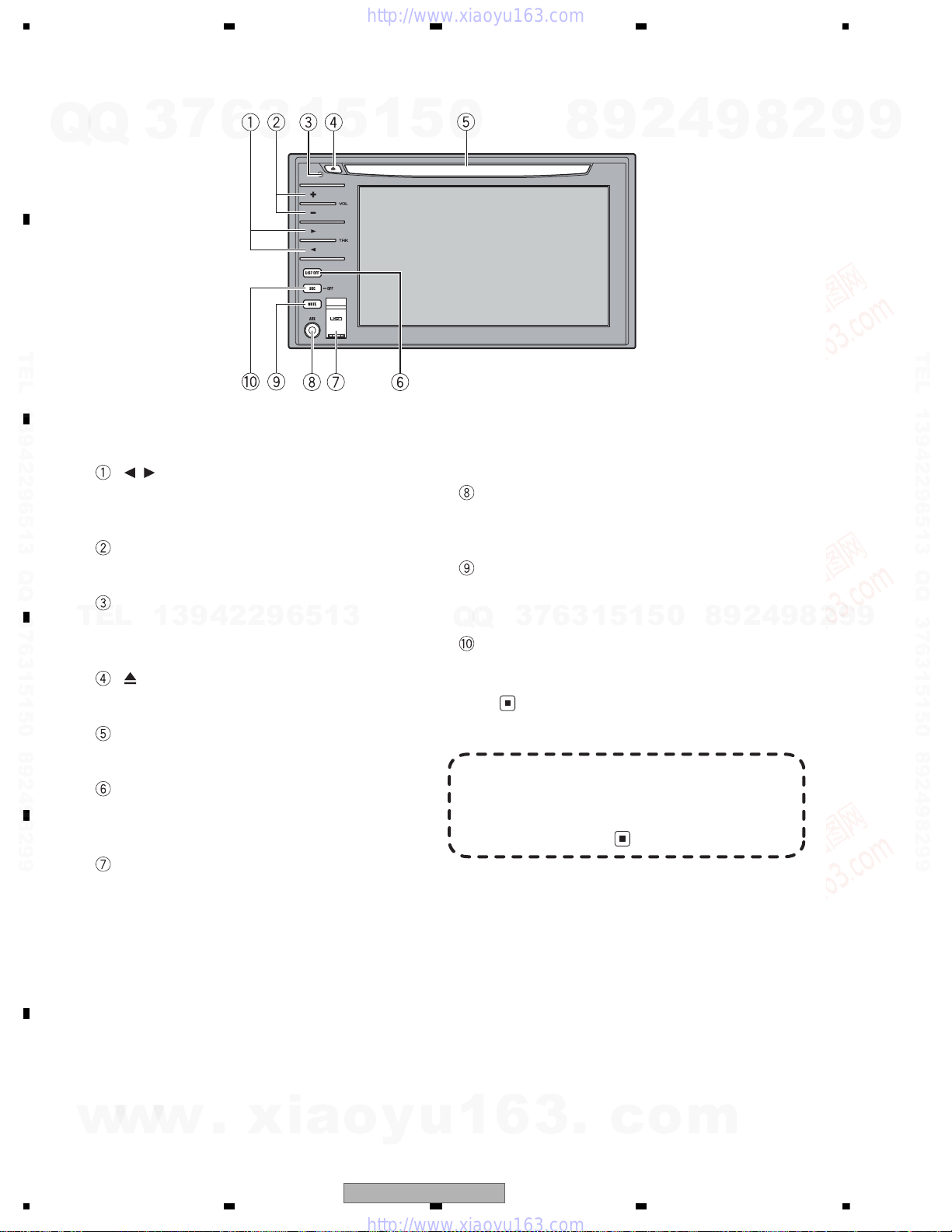
Head unit
/ (TRK) buttons
Press to do manual seek tuning, fast forward, reverse and track search controls.
+/– (VOL) buttons
Press to increase or decrease the volume.
RESET button
Press to return to the factory settings (initial
settings).
(eject) button
Press to eject a disc from this unit.
Disc loading slot
Insert a disc to play.
DISP OFF button
Press to turn the information display on or
off.
USB port
Use to connect a USB storage device.
• When connecting, open up the USB connector lid.
• Use a USB cable to connect the USB storage device to the USB port. Since the
USB storage device is projected forward
from the unit, it is dangerous to connect
directly.
Pioneer CD-U50E USB cable is also available. For details, consult your dealer.
AUX1 input jack (3.5 mm stereo/video
jack)
Use to connect an auxiliary device.
MUTE button
Press to turn off the sound. To turn on the
sound, press again.
SRC/OFF button
Press to cycle through all the available
sources. Press and hold to turn the source
off.
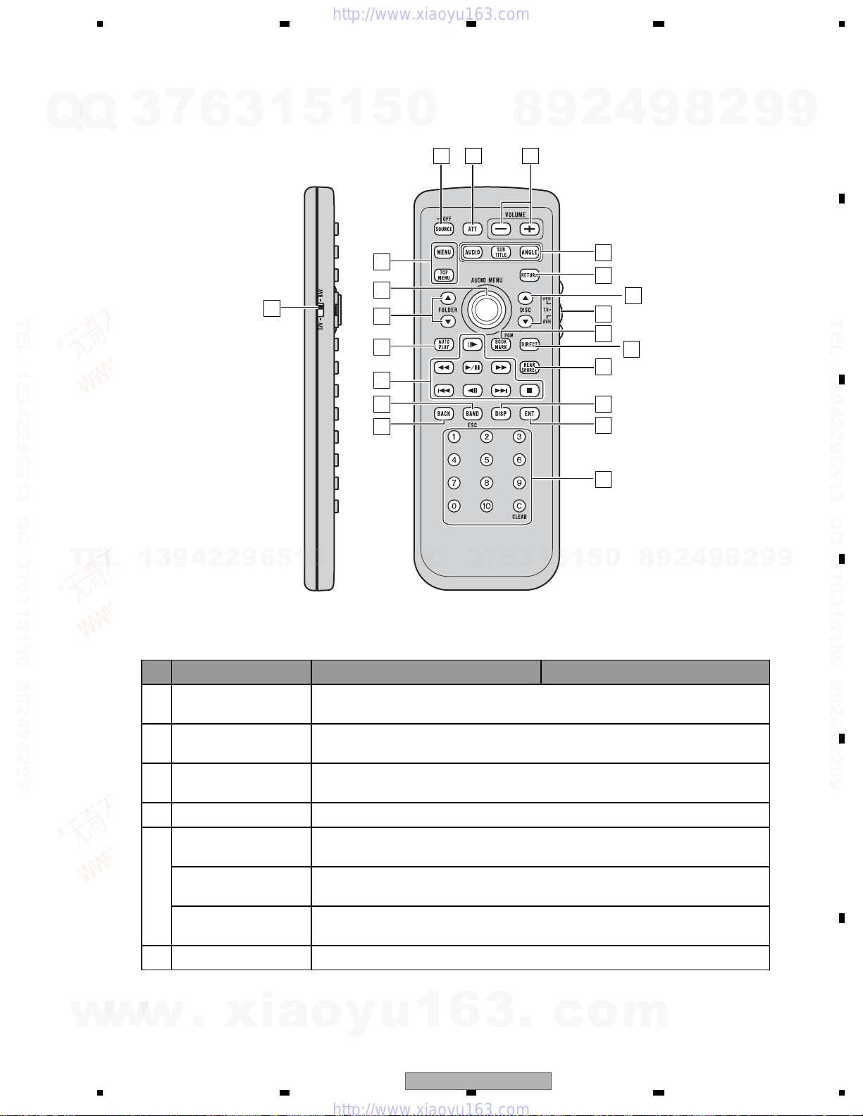
Optional remote control
The remote control CD-R55 is sold separately.
For details concerning operations, see the remote control manual.
AVH-P3100DVD/XN/UC
2.3 PANEL FACILITIES
Q
TEL 13942296513 QQ 376315150 892498299
Q
3
7
6
3
1
5
1
5
0
8
9
2
4
9
8
2
9
9
TEL 13942296513 QQ 376315150 892498299
TEL
w
13942296513
w
w
.
xia
o
Q
Q
y
u
1
6
3
6
7
3
3
.
1
5
c
1
0
5
o
9
8
m
2
4
9
8
2
9
9
12
AVH-P3100DVD/XN/UC
5678
56
7
8
C
D
F
A
B
E
3
0
8
6
5
9
Q
AVH-P3150DVD/XN/RC, AVH-P3150DVD/XN/RD, AVH-P3150DVD/XN/RI
Q
3
7
6
3
1
5
1
5
0
8
9
2
4
9
8
2
9
9
2
21
2
TEL 13942296513 QQ 376315150 892498299
TEL
13942296513
1
9
8
7
6
5
7
3
Q
Q
6
3
4
1
5
1
5
0
7
0
4
2
9
8
9
8
2
9
TEL 13942296513 QQ 376315150 892498299
9
w
w
Remote control
Button names AVH mode DVD mode
Remote control selec-
1
tion switch
2 SRC/OFF button
3ATTbutton
4 VOLUME buttons Press to increase or decrease the volume.
AUDIO button
5
SUBTITLE button
ANGLE button
6 RETURN button Press to display the PBC (playback control) menu during PBC playback.
w
.
xia
Switch to change the setting of the remote control. For details, refer to Setting remote control code type.
Press to cycle through all the available sources. Press and hold to turn the source
off.
Press to quickly lower the volume level by about 90%. Press once more to return to
the original volume level.
Press to change the audio language during DVD playback while using the built-in
DVD player.
Press to change the subtitle language during DVD playback while using the built-in
DVD player.
Press to change the viewing angle during DVD playback while using the built-in
DVD player.
o
y
u
1
6
3
.
c
o
m
AVH-P3100DVD/XN/UC
13
1234
1234
C
D
F
A
B
E
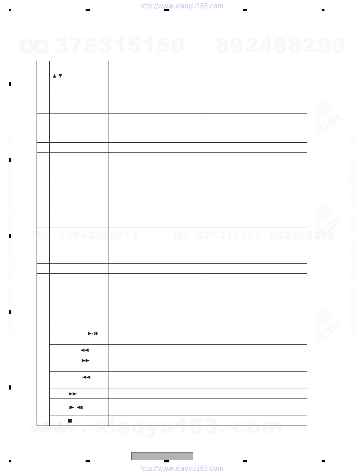
7 / buttons (DISC ) Not used.
Remote control code: AVH or B
Not used.
Remote control code: A
Press to select the next/previous disc.
8
Remote control operation mode switch
Switch the operation mode betweenAVH, DVD and TV modes. Normally, set to
AVH. For details, refer toUsing the remote control operation mode switchon the
next page.
9
Bookmark button/
PGM button
Press to operate the preprogrammed
functions for each source.
Press to turn the bookmark function on
or off when your DVD player features
bookmark function. For details, refer to
DVD player’s operation manual.
10 DIRECT button Not used.
11 REAR SOURCE button Not used.
Remote control code: AVH
Not used.
Remote control code: A or B
Press to turn the DVD player on or off.
12 DISPLAY button Press to select different displays.
Remote control code: AVH
Not used.
Remote control code: A or B
Press to select different displays.
13
ENTERTAINMENT but-
ton
Not used.
14
0 to 10 buttons, CLEAR
button
Press0 to 10 to input numbers. Buttons
1 to 6 can operate the preset tuning for
the tuner or disc changing for DVD
player or multi-CD player. PressCLEAR
to clear the input numbers.
Press to select a menu item on a video
CD featuring PBC (playback control).
15 Back button Press to return to the previous display. Not used.
16 BAND/ESC button
Press to select the tuner band when
tuner is selected as a source. Also used
to cancel the control mode of functions.
Press to switch mode between compressed audio and audio data (CD-DA)
when playing discs with compressed
audio and audio data (CD-DA) such as
CD-EXTRA and MIXED-MODE CDs.
Press to switch mode between compressed audio and audio data (CD-DA)
when playing discs with compressed
audio and audio data (CD-DA) such as
CD-EXTRA and MIXED-MODE CDs.
17
PLAY/PAUSE (
)
button
Press to switch sequentially between playback and pause while using the built-in
DVD player.
REVERSE (
) button Press to perform fast reverse while using the built-in DVD player.
FORWARD(
) but-
ton
Press to perform fast forward while using the built-in DVD player.
PREVIOUS(
) but-
ton
Press to return to the previous track (chapter) while using the built-in DVD player.
NEXT(
) button Press to go to the next track (chapter) while using the built-in DVD player.
STEP(
/ ) buttons
Press to move ahead one frame at a time during DVD/VideoCD playback. Press and
hold for one second to activate slow playback while using the built-in DVD player.
STOP(
) button Press to stop playback while using the built-in DVD player.
7
Q
Q
TEL 13942296513 QQ 376315150 892498299
TEL
3
13942296513
6
3
1
5
1
5
0
Q
Q
3
7
6
8
3
9
1
5
1
2
5
4
0
9
8
9
8
2
4
2
9
8
9
2
9
9
TEL 13942296513 QQ 376315150 892498299
9
w
w
w
.
xia
o
y
u
1
6
3
.
c
o
m
14
AVH-P3100DVD/XN/UC
5678
56
7
8
C
D
F
A
B
E
7
Q
Q
TEL 13942296513 QQ 376315150 892498299
3
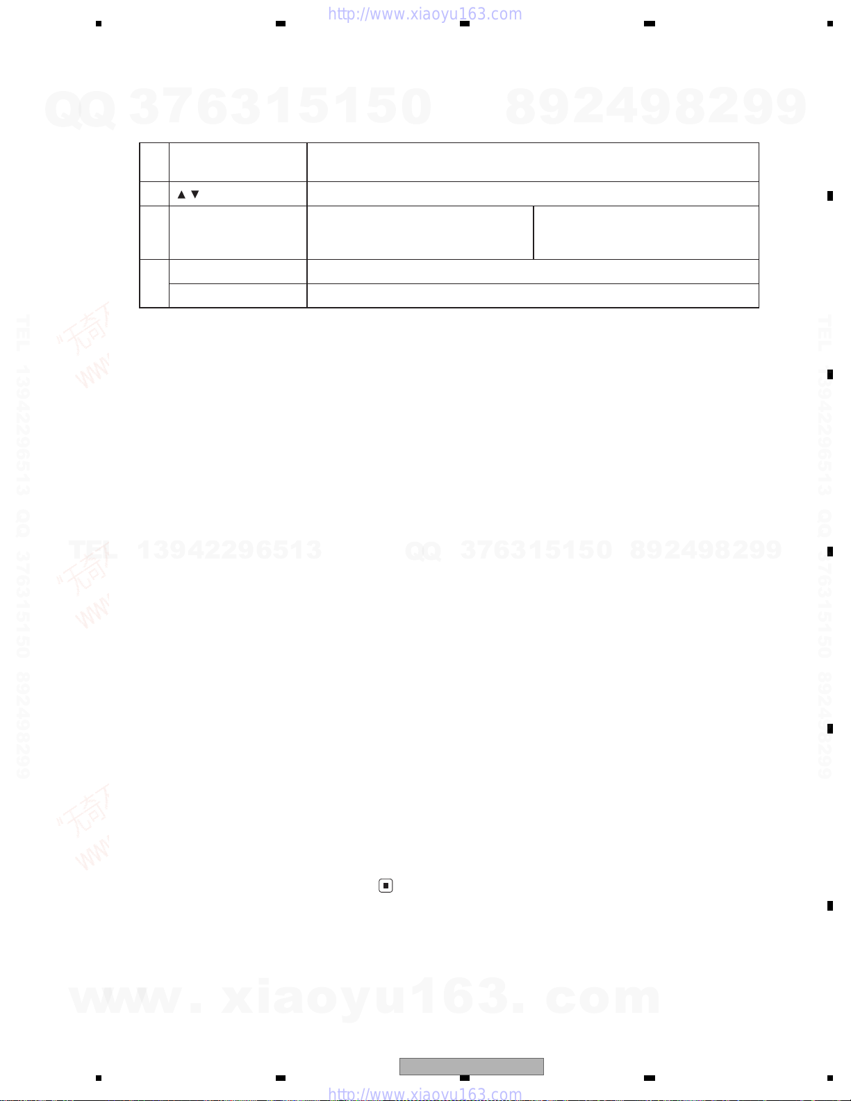
18 AUTO PLAY button
19 / buttons (FOLDER ) Press to select the next/previous folder.
20 Thumb pad
21
Using the remote control
operation mode switch
There are three remote control operation
modes on the remote control.
AVH mode operation
When operating this unit by remote control,
the mode is normally switched to AVH.
6
/
MENU button Press to display the DVD menu during DVD playback.
TOP MENU button Press to return to the top menu during DVD playback.
3
1
5
1
5
0
Press to turn the DVD auto-playback function on or off while using the built-in DVD
player.
Move to do fast forward, reverse and
track search controls. Click to recall
Menu.
4
2
9
8
Move to select a menu on the DVD
menu.
9
8
2
9
9
TEL 13942296513 QQ 376315150 892498299
TEL
DVD mode operation
13942296513
If you switch the mode toDVD, the thumb pad
and 0 to 10 operations are changed for the
DVD player.
When you want to operate the follow-
•
ing functions, switch the mode to DVD:
• When operating the DVD menu by using
the thumb pad.
• When operating the PBC menu by using 0
to 10.
TV mode operation
TV operations available with a Pioneer TV tuner
(e.g. GEX-P5750TV(P)) can be controled with
AVH mode. TV mode is not used with this
unit.
• For details concerning operation, refer to
the TV tuner’s operation manuals.
Q
Q
3
7
6
3
1
5
1
5
0
8
9
2
4
9
8
2
9
9
w
w
w
.
xia
o
y
u
1
6
3
.
AVH-P3100DVD/XN/UC
c
o
m
15
1234
1234
C
D
F
A
B
E
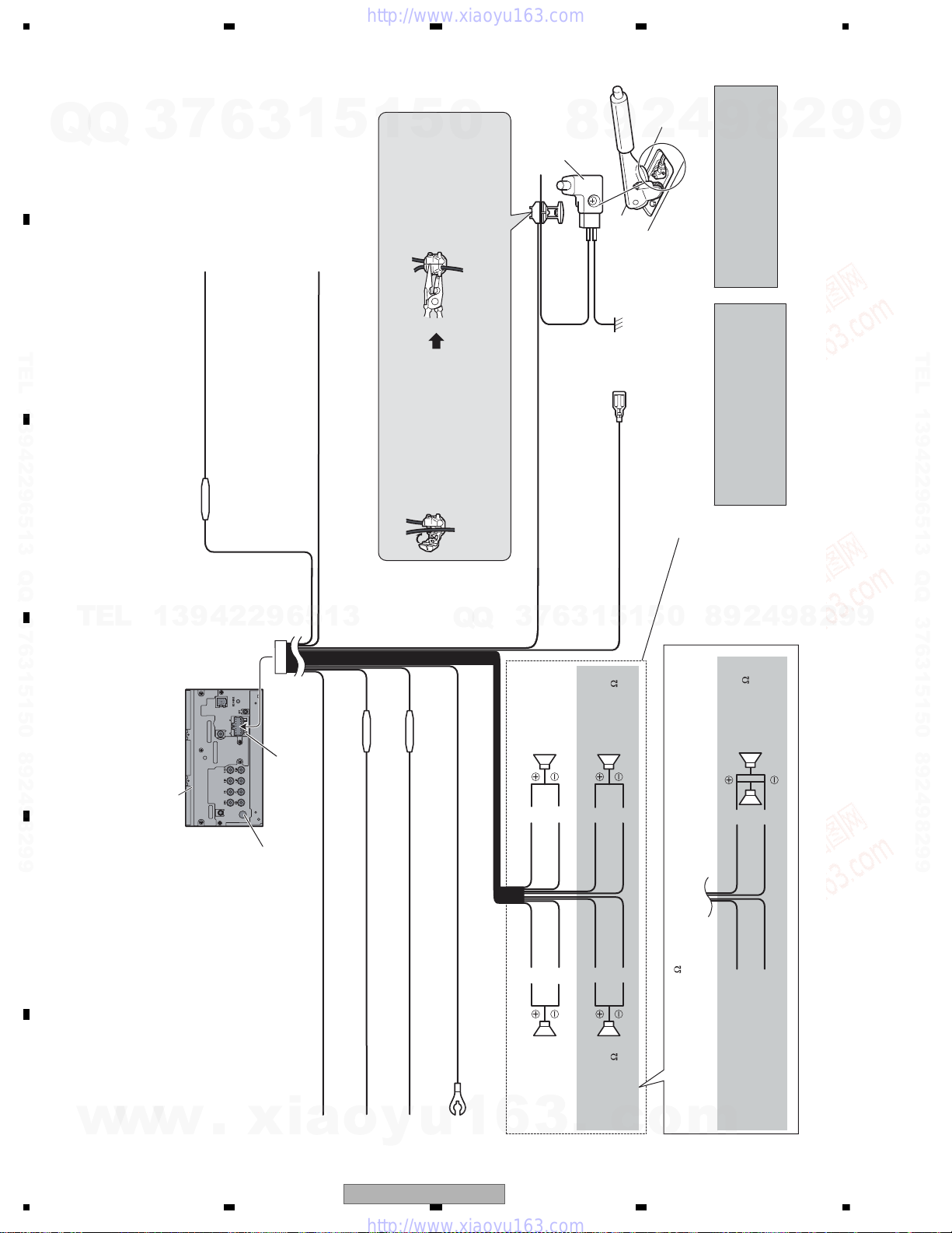
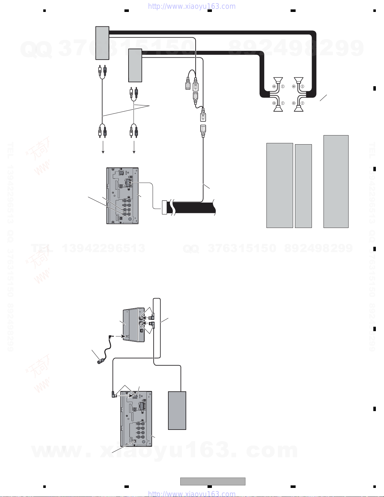
Connecting the power cord
Yellow
Connect to the constant 12 V supply terminal.
Fuse resistor
Red
Connect to terminal controlled by ignition switch (12 V DC).
Black (chassis ground)
Connect to a clean, paint-free metal location.
Left Right
rekaepstnorFrekaepstnorF
Rear speaker or
Subwoofer (4
)
White Gray
Gray/blackWhite/black
Green Violet
Green/black Violet/black
Violet
Violet/black
Not used.
Green
Green/black
When using a subwoofer of 70 W (2
), be sure to connect with Violet and Violet/black leads of this unit. Do not
connect anything to Green and Green/black leads.
Subwoofer (4
)
× 2
Rear speaker or
Subwoofer (4
)
Fuse (10 A)
This product
Antenna input
Orange/white
Connect to lighting switch terminal.
Fuse resistor
Connection method
1. Clamp the lead.
2. Clamp firmly with
needle-nosed pliers.
Note:
· The position of the parking brake switch depends on the vehicle model. For details,
consult the vehicle Owner’s Manual or dealer.
Yellow/black
If you use equipment with Mute function, wire this lead to the
Audio Mute lead on that piece of equipment. If not, keep the
Audio Mute lead free of any connections.
Light green
Used to detect the ON/OFF status of the parking
brake. This lead must be connected to the power
supply side of the parking brake switch.
Blue/white
Connect to system control terminal of the power amp or
auto-antenna relay control terminal (max. 300 mA 12 V DC).
Ground side
Power supply side
Parking brake
switch
Fuse resistor
With a 2 speaker system, do not connect anything to the speaker leads
that are not connected to speakers.
Note:
· Change the initial setting of this unit (refer
to the Operation Manual). The subwoofer
output of this unit is monaural.
Violet/white
Of the two lead wires connected to the back lamp, connect the one
in which the voltage changes when the gear shift is in the
REVERSE (R) position. This connection enables the unit to
sense whether the car is moving forwards or backwards.
When you connect the separately sold
multi-channel processor (DEQ-P8000(UC)
unit, do not connect anything to the speaker
leads and systemremote control (blue/white).
/ DEQ-P7650(RC, RD, RI)) to this
2.4 CONNECTION DIAGRAM
Q
TEL 13942296513 QQ 376315150 892498299
Q
3
7
6
3
1
5
1
5
0
8
9
2
4
9
8
2
9
9
TEL 13942296513 QQ 376315150 892498299
TEL
13942296513
Q
Q
5
1
3
6
7
3
1
5
0
8
9
4
2
9
8
2
9
9
w
w
16
w
.
xia
o
y
u
1
AVH-P3100DVD/XN/UC
6
3
.
c
o
m
5678
56
7
8
C
D
F
A
B
E
7
Q
Q
TEL 13942296513 QQ 376315150 892498299
3
6
Rear output or
subwoofer output
When connecting to separately sold power amp
1
3
Power amp
(sold separately)
To rear output or
subwoofer output
Front output
5
1
Power amp
(sold separately)
To front output
This product
5
0
Connect with RCA cables (sold
separately)
System remote control
Blue/white
rekaepstnorFrekaepstnorF
4
2
9
8
thgiRtfeL
Connect to system control terminal of the
power amp or auto-antenna relay control
terminal (max. 300 mA 12 V DC).
/ DEQ-P7650 (RC, RD, RI)) to this
When you connect the separately sold
multi-channel processor (DEQ-P8000 (UC)
unit, do not connect anything to the speaker
9
Rear speaker
or Subwoofer
Rear speaker
or Subwoofer
leads and systemremote control (blue/white).
When you connect the multi-channel processor
to this unit, refer to multi-channel processor’s
installation manual for the connection method.
Perform these connections when
Note:
2
8
9
9
using the optional amplifier.
(refer to the Operation Manual).
The subwoofer output of this unit is monaural.
· Change the initial setting of this unit
TEL 13942296513 QQ 376315150 892498299
TEL
13942296513
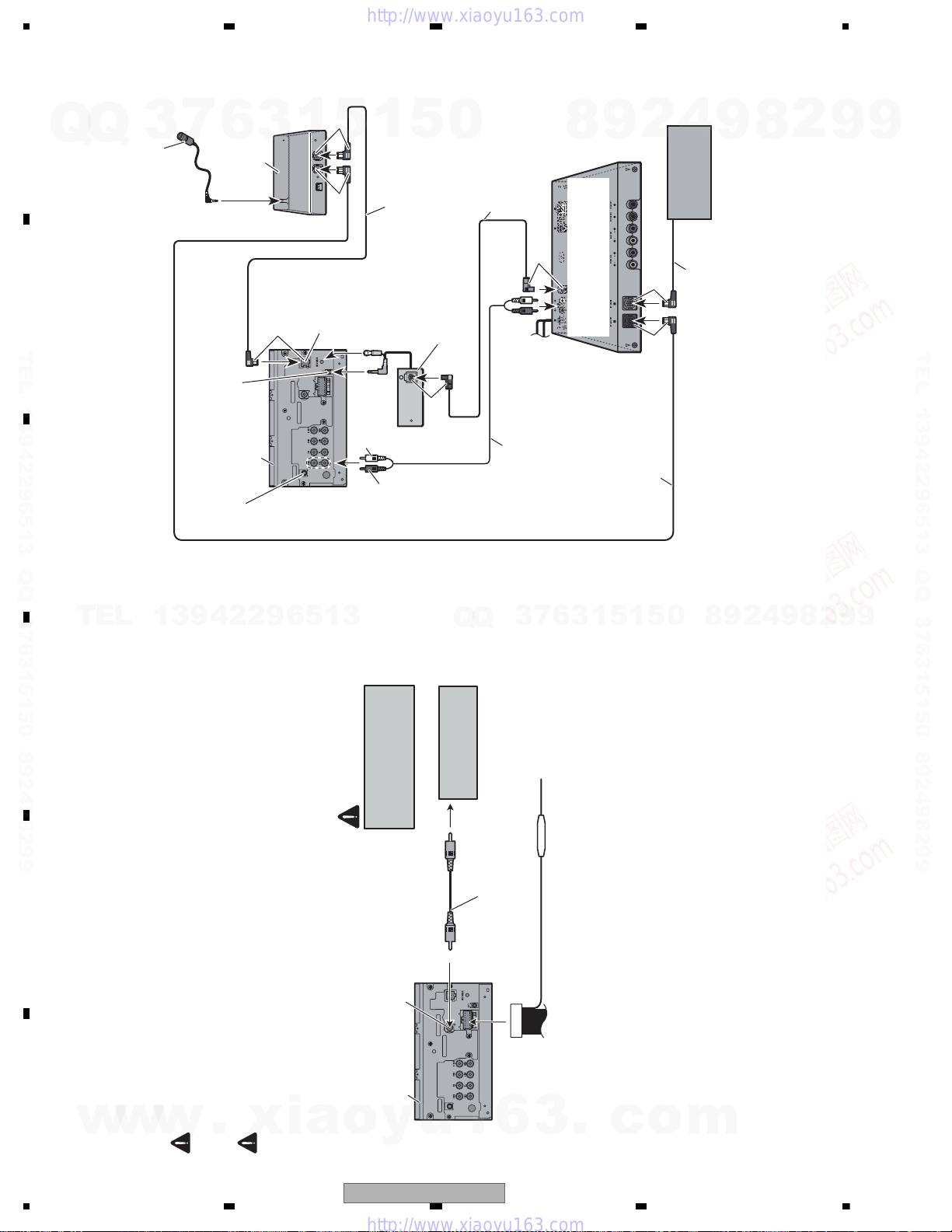
Bluetooth adapter
(e.g. CD-BTB200 (UC))
(sold separately)
(e.g. CD-BTB100 (RC, RD, RI))
Microphone
for hands-free phoning
(supplied with Bluetooth adapter)
Blue
Black
Blue
IP-BUS input
(Blue)
7
3
Q
Q
IP-BUS cable
(Supplied with Bluetooth adapter)
IP-BUS cable
Multi-CD player
(sold separately)
6
3
1
5
1
5
0
8
9
2
4
9
8
2
9
9
This product
w
w
w
.
xia
Wired remote input
Hard-wired remote control
adaptor can be connected
Connecting the system
(sold separately).
o
y
u
1
6
3
.
AVH-P3100DVD/XN/UC
c
o
m
17
1234
1234
C
D
F
A
B
E
When connecting with a rear view camera
When this product is used with a rear view camera, it is possible to automatically switch
from the video to rear view image when the gear shift is moved to REVERSE (R).
WARNING
USE INPUT ONLY FOR REVERSE OR MIRROR IMAGE REAR VIEW CAMERA. OTHER USE MAY
RESULT IN INJURY OR DAMAGE.
CAUTION
• The screen image may appear reversed.
• The rear view camera function is to be used as an aid for backing into a tight parking spot.
Do not use this function for entertainment purposes.
• Objects in the rear view may appear closer or more distant than they actually are.
RCA cable
(sold separately)
To video output
Rear view camera
Rear view camera input
(REAR CAMERA IN )
This product
Violet/white
Of the two lead wires connected to the back lamp, connect the one
in which the voltage changes when the gear shift is in the
REVERSE (R) position. This connection enables the unit to
sense whether the car is moving forwards or backwards.
You must use a camera
which outputs mirror
reversed images.
CAUTION
Fuse resistor
• It is necessary to set Camera Polarity properly in System Menu when connecting the rear
view camera.
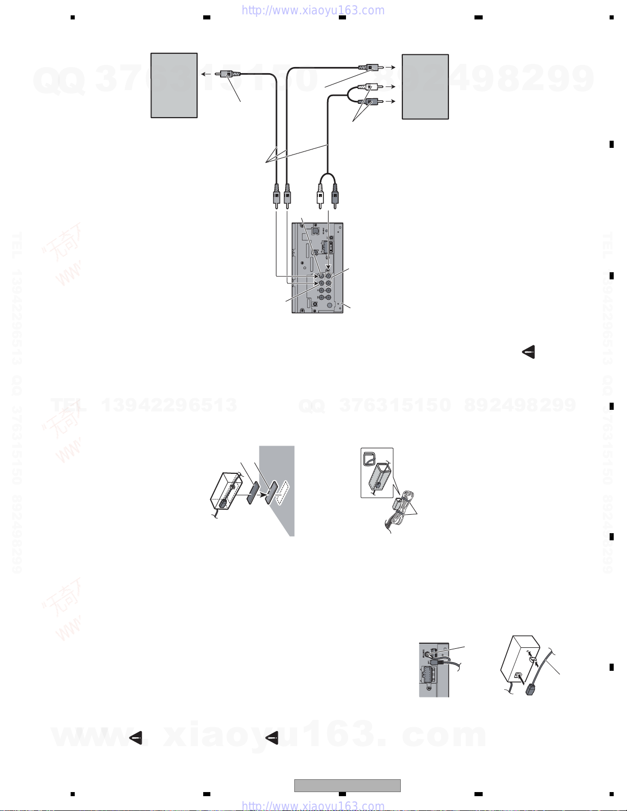
When connecting with a multi-channel processor
Black
IP-BUS cable (supplied with
multi-channel processor)
RCA cable (supplied with
multi-channel processor)
Optical cable
(supplied with
multi-channel processor)
This product
Wired remote input
Hard-wired remote control
adaptor can be connected
(sold separately).
IP-BUS cable
(Supplied with Bluetooth adapter)
Black
Bluetooth adapter
(e.g. CD-BTB200 (UC))
(sold separately)
Microphone
for hands-free phoning
(supplied with Bluetooth adapter)
Blue
Black
Optical cable connection box
(supplied with multi-channel processor)
To SWL
To SWR
Blue
Optical output
(Black)
IP-BUS input
(Blue)
Blue
Multi-channel processor
(DEQ-P7650 (RC, RD, RI))
(DEQ-P8000 (UC))
(sold separately)
Blue
Multi-CD player
(sold separately)
IP-BUS cable
(e.g. CD-BTB100 (RC, RD, RI))
7
Q
Q
TEL 13942296513 QQ 376315150 892498299
3
6
3
1
5
1
5
0
9
8
4
2
9
8
2
9
9
TEL 13942296513 QQ 376315150 892498299
TEL
13942296513
Q
Q
9
4
2
9
8
0
5
1
5
1
3
6
7
3
8
2
9
9
w
w
18
w
.
xia
o
y
u
1
6
AVH-P3100DVD/XN/UC
3
.
c
o
m
5678
56
7
8
C
D
F
A
B
E
7
Q
Q
TEL 13942296513 QQ 376315150 892498299
3
6
When connecting the external video component and the
display
1
3
Display with RCA
input jacks (sold
separately)
5
1
5
0
To video input
RCA cables (sold separately)
Video input (V IN )
To video output
Rear monitor output
(V OUT )
To audio outputs
8
Audio input
(L IN, R IN )
This product
9
4
2
External video
component (sold
separately)
2
8
9
This product’s rear video output is for connection of a display to enable passengers in the
component.
• It is necessary to change AV Input in System Menu when connecting the external video
rear seats to watch video.
When using a display connected to rear video output
9
WARNING
Never install the display in a location where it is visible to the driver while driving.
9
TEL 13942296513 QQ 376315150 892498299
TEL
13942296513
Install the optical cable connection box
using the hook and loop fastener in the
connection box with the hook and
• When installing the optical cable
Installing the optical cable
connection box
ample space of the console box.
loop fastener.
Loop fastener
Hook fastener
1
3
6
7
3
Q
Q
Wrap with the protection tape
Wrap the optical cable and connection box
with the protection tape and fasten with the
power code using the lock tie.
connection box with the lock tie.
• When installing the optical cable
5
1
5
Fasten with the lock tie
0
8
9
Screw
2
4
9
8
2
9
9
WARNING
box in locations where the operation of safety
devices such as airbags is prevented by this
unit. Otherwise, there is a danger of a fatal
accident.
box in locations where the operation of the
brake may be prevented. Otherwise, it may
result in a traffic accident.
Connecting and installing the optical cable connection box
w
w
w
• Avoid installing the optical cable connection
.
xia
• Avoid installing the optical cable connection
with the hook and loop fastener or lock tie. If
• Fix the optical cable connection box securely
o
CAUTION
the unit is loose, it disturbs driving stability,
which may result in a traffic accident.
y
u
Connect the optical cable so that it does not
protrude from the main unit, as shown in the
illustration. Fasten the ground lead to the
lead to the main unit.
this unit. If other parts are used, this unit may be
damaged or could dismount itself, which leads to
an accident or other problems.
rainwater is likely to be spilled on the unit.
Incursion of water into the unit may cause smoke
or fire.
• Install this unit using only the parts supplied with
• Do not install this unit near the doors where
1
6
AVH-P3100DVD/XN/UC
1. Connect the optical cable and ground
Connecting the optical cable
3
.
protrusion on the back of the main unit.
c
o
optical cable connection box.
2. Connect the optical cable to the
m
Optical cable
19
1234
1234
C
D
F
A
B
E
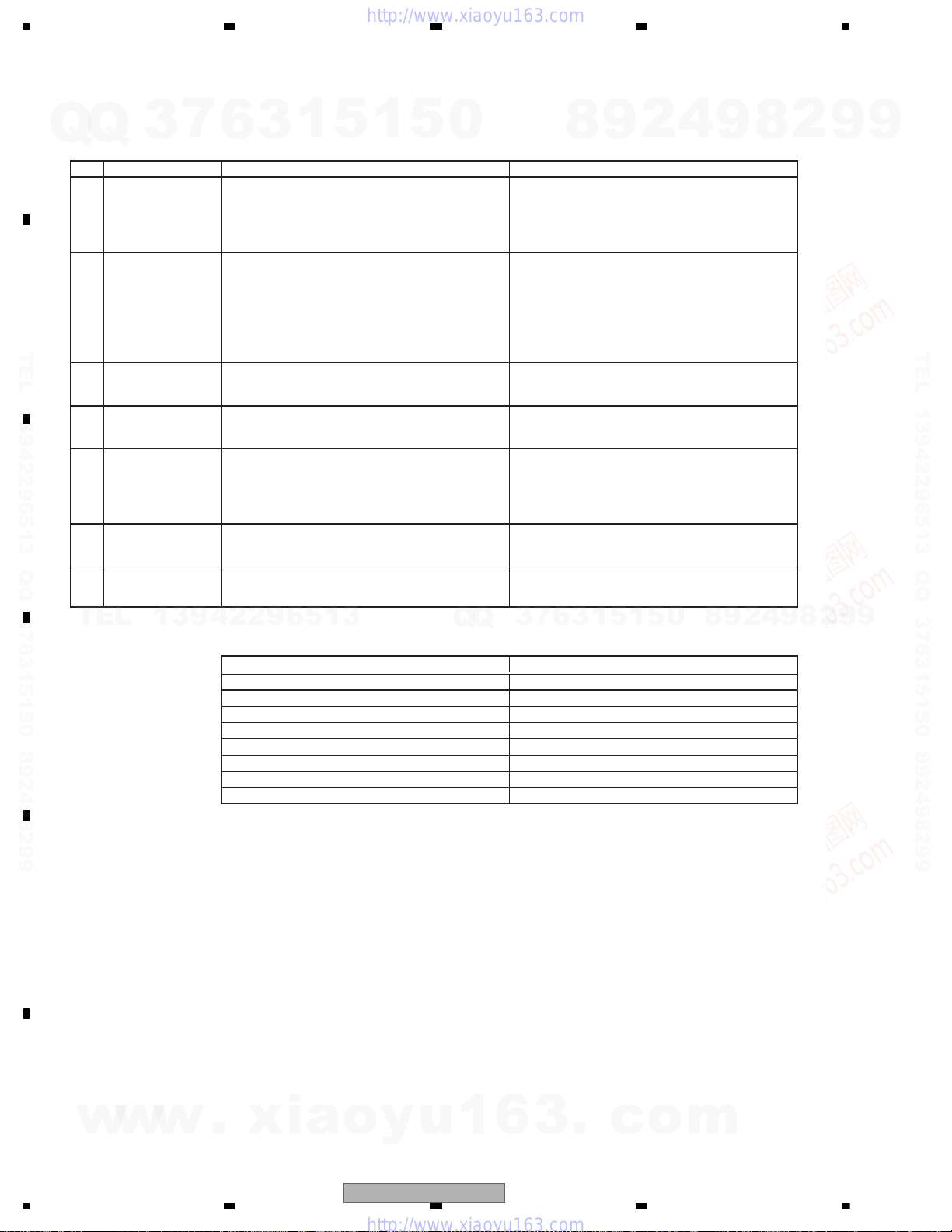
To keep the product quality after servicing, please confirm following check points.
No. Procedures Item to be confirmed
1 Confirm whether the customer complain has
been solved.
If the customer complain occurs with the
specific media, use it for the operation check.
The customer complain must not be
reappeared.
Display, video, audio and operations must be
normal.
2 DVD Measure playback error rates at the
innermost and outermost tracks by using the
test mode with the following disc.
DVD test disc (TDV-582)
Deterioration of mecha-drive can be
checked.
The error rate must be less than the
threshold value.
(Refer to the chapter of DIAGNOSIS for the
threshold value.)
3 DVD Play back a DVD.
(Menu operation; Title/chapter search)
Display, video, audio and operations must be
normal.
4 CD Play back a CD.
(Track search)
Display, audio and operations must be
normal.
5 FM/AM tuner Check FM/AM tuner action.
(Seek, Preset)
Switch band to check both FM and AM.
Display, audio and operations must be
normal. * If the reception sensitivity is poorer
than normal, the gasket on the FM/AM tuner
unit may be damaged or lost.
6 Check whether no disc is inside the product. The media used for the operating check must
be ejected.
7 Appearance check No scratches or dirt on its appearance after
receiving it for service.
For check items concerning image and voice, please refer to the followings:
Check items concerning image Check items concerning voice
Block-noise Distortion
Crosscut noise Noise
Dot noise Low volume
Distorted image (Image skip) High volume
Low brightness Changes in level
Too bright Pause of sound
Color fading
Partial discoloration
3. BASIC ITEMS FOR SERVICE
3.1 CHECK POINTS AFTER SERVICING
Q
TEL 13942296513 QQ 376315150 892498299
7
Q
TEL
3
13942296513
6
3
1
5
1
5
0
3
Q
Q
7
6
8
3
1
9
5
2
1
5
4
0
9
8
9
8
2
4
2
9
8
9
2
9
9
TEL 13942296513 QQ 376315150 892498299
9
w
w
w
.
xia
o
y
u
1
6
3
.
c
o
m
20
AVH-P3100DVD/XN/UC
5678
56
7
8
C
D
F
A
B
E
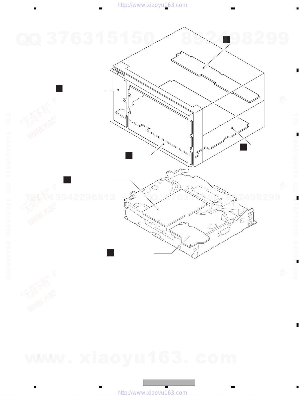
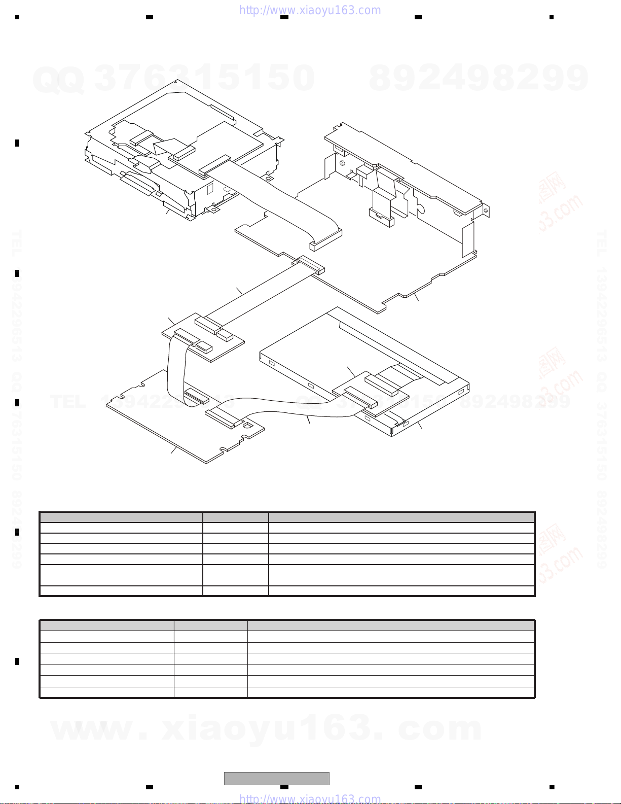
B
IF PCB
A
Mother PCB
E
Keyboard PCB
F
Monitor Unit
C
DVD Core Unit
D
Connect PCB
Mother Unit
Consists of
Mother PCB
IF PCB
Keyboard PCB
Unit Number : CWN3777(UC)
Unit Number : CWN3778(RC)
Unit Number : CWN3779(RD)
Unit Number : CWN3780(RI)
Unit Name : Mother Unit
Unit Number : CWN3783
Unit Name : Monitor Unit
Unit Number : YWX5007
Unit Name : DVD Core Unit
Unit Number :
Unit Name : Connect PCB
3.2 PCB LOCATIONS
7
Q
Q
TEL 13942296513 QQ 376315150 892498299
3
6
3
1
5
1
5
0
8
9
2
4
9
8
2
9
9
TEL 13942296513 QQ 376315150 892498299
TEL
w
13942296513
w
w
.
xia
3
Q
Q
o
y
u
1
6
AVH-P3100DVD/XN/UC
6
7
3
1
5
1
3
.
c
0
5
o
9
8
m
2
4
9
8
2
9
9
21
1234
1234
C
D
F
A
B
E
Name Jig No. Remarks
60-Pin Relay PCB GGF1495 LCD <--> 60-Pin FFC (GGD1380)
60-Pin FFC GGD1380 60-Pin Relay PCB (GGF1495) <--> Monitor Unit (CN6001)
40-Pin + 20-Pin Relay PCB GGF1461 Monitor Unit (CN5001) <--> FFC (CDE8744)
40-Pin FFC GGD1170 40-Pin + 20-Pin Relay PCB (GGF1461) <--> Mother PCB (CN501)
Disc
TDV-582 Skew adjustment, Check points after servicing,
Inspection method of Pickup Unit
Disc TCD-782 Inspection method of Pickup Unit
- Jigs List
Mother PCB
LCD
Monitor Unit
DVD Module
GGD1170
GGF1461
GGD1380
GGF1495
- Grease List
Name
Grease
Grease
Grease
Locking agents
Bond
Bond
Jig No.
GEM1024
GEM1038
GEM1045
1401M
GEM1033
1530
Remarks
DVD Mechanism Module
DVD Mechanism Module
DVD Mechanism Module
Skew adjustment (1401M:produced by THREE BOND)
Skew adjustment
Skew adjustment (1530:produced by THREE BOND)
3.3 JIGS LIST
Q
TEL 13942296513 QQ 376315150 892498299
Q
3
7
6
3
1
5
1
5
0
8
9
2
4
9
8
2
9
9
TEL 13942296513 QQ 376315150 892498299
TEL
13942296513
5
1
3
6
7
3
Q
Q
1
5
0
8
9
2
4
9
8
2
9
9
w
22
w
w
.
xia
o
y
u
1
6
3
.
c
AVH-P3100DVD/XN/UC
o
m
5678
56
7
8
C
D
F
A
B
E
Before shipping out the product, be sure to clean the following portions by using the prescribed cleaning tools:
Portions to be cleaned Cleaning tools
DVD pickup lenses Cleaning liquid : GEM1004
Cleaning paper : GED-008
Portions to be cleaned Cleaning tools
Fans Cleaning paper : GED-008
3.4 CLEANING
7
Q
Q
TEL 13942296513 QQ 376315150 892498299
3
6
3
1
5
1
5
0
8
9
2
4
9
8
2
9
9
TEL 13942296513 QQ 376315150 892498299
TEL
13942296513
Q
Q
3
7
6
3
1
5
1
5
0
8
9
2
4
9
8
2
9
9
w
w
w
.
xia
o
y
u
1
6
3
.
AVH-P3100DVD/XN/UC
c
o
m
23
1234
1234
C
D
F
A
B
E
CN501
151617181920212223242526272829303132333435
3637383940
CN901
1
2
3
4
5
6
7
8
9
10
11
12
13
14
15
16
17
18
19
20
21
22
23
24
25
26
27
28
29
30
40FY-BMGB(LF)(SN)
CN121
ONSEI-
7
ONSEI+
8
GNDAU
9
CCAUR10CCAUL11GNDSIG
12
CSYNC
13
GNDSIG
14
ANB15GNDSIG16ANG17GNDSIG
18
ANR
19
NC20WIRED
21
WIREDAD
22
GNDD
23
GNDV24BCAM_VGGND
25
BCAM_IN
26
AUXV27AUVGND
28
MAINTEST
29
AUXR30AUAGND
31
AUXL
32
BUSL-33BUSL+34GND35BUSR-36BUSR+37ASENSB0
38
BUS+39BUS-40
CN521
GND
1
USBDP
2
USBDM
3
USBGND
4
USB5V
5
AUVGND
6
AUX_V
7
AUAGND
8
AUX_R
9
AUX_L
10
CN5001
1
GNDILM
2
GNDFL3GNDFL
4
GNDFL
5NC6
PWRFL7PWRFL8PWRFL
9
NC
10
GNDD11GNDD12GNDD13GNDV
14
MONVBS
15
GNDV
16
GNDRGB
17
CSYNC
18
NAVI_R19NAVI_G20NAVI_B21GNDRGB
22
GNDP23GNDP24GNDP
25
NC
26
PWRVI
CN5004
1
GNDKEY
2
ILMB
3
LEDR1
4
LEDG1
5
LEDB1
6
HDRST
7
KDT1
8
KDT0
9
REM
10
SWVDD33
1
VCOM
2VCOM
3NC
4
VEE
5NC6SPS
7U/L
8CLS
9MODE
10CS
11GND
12NC
13VDD
14NC
15SPR
16
VCC
17VSHD
18NC
19GND
20CLD
21
GND
22GND
23NC
24VSHA
25VSHA
26NC
CN3003
1
2
3
4
5
6
7
8
9
10
CN3001
1
2
3456789
10
CN3002
1
USB5V
2
USDM
3
USDP
4
USGND
5
USGND
JA3001
1
S
AUXV
2
T
AUXL
3
R1
AUXR
4
R2
GND
CN2002
1234567
8
9
10111213141516
17
181920212223242526
27282930313233
34
JA2003
2 B.CAM_IN
1
BCV_GND
JA2001
2
3
1
AMUTE
DGND
DGND
DGND
DGND
AGND
VDD5
CPRST
IECOUT
VD
AGND
LS1
SRX
XRES
STANBY
VGND
IRQPWR
PGND
PGND
S
LS1TX
DGND
SCK
SDA
VD
D+
AGND
VD
ROUT
D-
COMPOSIT
LOUT
MINIJACK
B.CAM INPUT WIRED REMOTE
USB
F
MONITOR UNIT
A
MOTHER PCB
1/4
A
2/4
A
3/4
A
4/4
A
B
IF PCB
E
KEYBOARD
PCB
C
DVD MECHANISM MODULE
(LS1)
D
MONITOR UNIT(uCOM)
1/2
F
MONITOR UNIT(MONITOR)
2/2
F
MOTHER PCB(ANALOG)
MOTHER PCB(TUNER)
MOTHER PCB(SYSTEM)
MOTHER PCB(POWER SUPPLY)
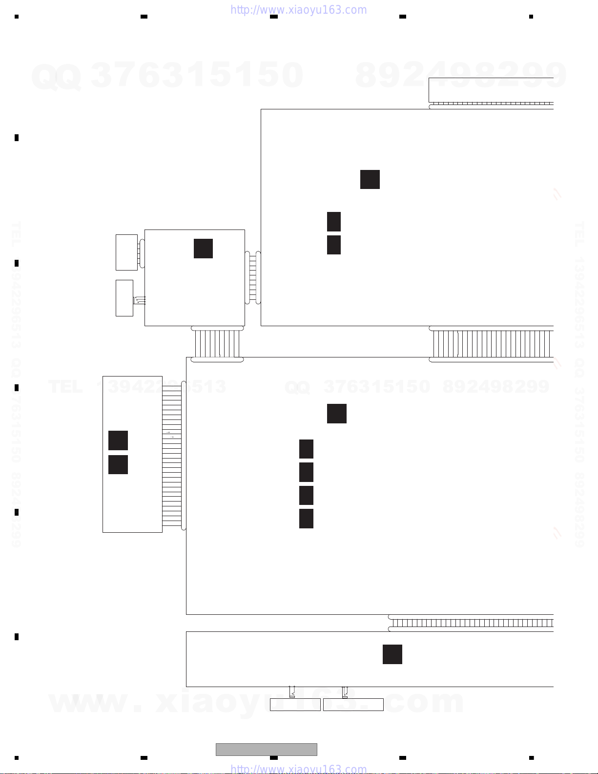
4. BLOCK DIAGRAM
4.1 OVERALL CONNECTION DIAGRAM
7
Q
Q
3
6
TEL 13942296513 QQ 376315150 892498299
3
1
5
1
5
0
TEL
13942296513
Q
Q
2
9
8
0
5
1
5
1
3
6
7
3
4
9
8
9
2
8
4
2
8
9
2
9
9
9
TEL 13942296513 QQ 376315150 892498299
9
c
o
3
.
w
w
w
24
.
xia
o
y
u
AVH-P3100DVD/XN/UC
1
6
m

5678
56
7
8
C
D
F
A
B
E
CN501
1
2345678
9
1011121314151617181920212223242526
GNDD1NAVI_TO_SYS
2
SYS_TO_NAVI
3
GUIDEON
4
TVON5NC
6
ONSEI-
7
ONSEI+
8
GNDAU
9
CCAUR10CCAUL11GNDSIG
12
CSYNC
13
GNDSIG
14
ANB15GNDSIG16ANG17GNDSIG
18
JA141
1
2
3
4
5
6
7
8
9
10
11
12
13
14
15
16
JA101
REAR_R
REAR_L
SW_R
SW_L
FRONT_R
FRONT_L
GND
GND
GND
GND
1
234
5
6
789
10
JA102
VCR_RG
1
VCR_RIN
2
VOUT_G
3
VOUT
4
VCR_LG
5
VCR_LIN
6
VCR_VG
7
VCR_VIN
8
JA951
2
3
1
CN5001
15
GNDV
16
GNDRGB
17
CSYNC
18
NAVI_R19NAVI_G20NAVI_B21GNDRGB
22
GNDP23GNDP24GNDP
25
NC
26
PWRVI27PWRVI28PWRVI
29
SWVDD3330SWVDD33
31
ILMB
32
MONRST
33
S_MTX
34
M_SRX
35
MFLPWR
36
HDRST
37
GNDOSD
38
GNDOSD39GNDILM40GNDILM
CN6101
1
A2+
2
NC
3
A1+
4
NC
5
A1-
6
NC
7
A2-
8
NC
9
TH
10
TH_G
CN5401
1
NC
2
PLYV
3
PLYV
4
PLXV
5
PLXV
6
ADVX
7
ADVX
8
ADVY
9
ADVY
10
NC
CN6001
15SPR
16
VCC
17VSHD
18NC
19GND
20CLD
21
GND
22GND
23NC
24VSHA
25VSHA
26NC
27
GND
28LBR
29LS30R5
31R432R3
33R2
34R1
35R0
36G537G4
38G339G2
40G1
41G0
42B5
43B4
44B3
45B246B1
47B048V10
49V9
50NC
51V7
52NC
53V5
54NC
55V3
56NC
57NC
58V0
59SPL
60GND
232425
26
2728293031
323334
35
3637383940
JA2004
1
BUS+2BUSG3BUSLG4MAINTEST5BUS-6BUSRG7BUSL+8ASENBO9BUSR+10BUSR-11BUSL-
JA401
1
2
3
P.B.
BGSENS
FR+
RR-
ILM
FR-
B.UP
ACC
FL+
MUTE
RR+
RL+
B.REM
RL-
FL-
POWER SUPPLY
RCA OUTVCR IN
S/PDIF OUT
BACKLIGHT
TOUCH PANEL
CWX3692
LCD MODULE
IP BUS
FM/AM ANT
CSX1143
7
3
Q
Q
6
3
1
5
1
5
0
TEL 13942296513 QQ 376315150 892498299
TEL
13942296513
Q
Q
3
7
6
8
3
9
1
5
1
2
5
4
9
9
8
0
8
2
4
2
9
8
2
9
9
9
TEL 13942296513 QQ 376315150 892498299
9
w
w
w
.
xia
o
y
u
1
6
3
.
c
o
m
AVH-P3100DVD/XN/UC
25

1234
1234
C
D
F
A
B
E
6
8
4
VCR IN
LOUT
MOTHER PCB (1/2)
A
CN901
CN521
JA102
AV SELECTOR
IC301
AN15887A
41
15
L3-1
V3-1
28
LOUT1
34
VOUT1
33
FB1
32
L2-1
V2-1
VOUT2
C
2
3
5
6
14
24
3
4
18
19
20
12
8
9
21
22
23
2
8
11
U
U
36
SCL
144
A
35
SDA
1
A
39
VD5
VD8
VDD5
VD
CPRST
SDA
SCK
STANBY
LS1
→
SRX
S
→
LS1TX
IRQPWR
XRES
AMUTE
STNDBY
IRQPW
MS_SRX
S_MSTX
XRES
AMUTE
VCR_LIN
VCR_VIN
VOUT
D+
D-
USB5V
7
AUX_V
10
AUX_L
USBDP
USBDM
COMPOSIT
VDCNT5
IECOUT
10
S
17
R
31
T
IR
13
18
27
29
X
A
IRQPW
USBFLG
AMUTE
STNDBY
XRES
MS-SRX
S-MSTX
USBCNT
EN
OC
VOUT
VIN
USB 5V
IC521
R5523N001B
IC951
TC7SET08FUS1
A
W
W
138
M
73
T
R
139
75
123
125
LS_L
BUSL+
BUSL-
LOUT
TUN_L
IN1_L
3
4
IN4-_L
IN4+_L
7
IN2_L
6
2
IN5+_L
JA2003
CN2002
BUSL+
BUSL+
BUSL-
ASENBO
ASENBO
MAINTEST
BUS-
BUS+
BUSL-
MAINTEST
BUS+
BUS-
IF PCB
B
B.CAMERA
INPUT
IP BUS
7
11
1
5
8
4
7
15
8
3
12
2
1
19
20
BCAM_INB.CAM_IN
BCV_GND
2
1
JA2004
VCR_L
V1-1
37
LS-V
VCR_V
SPDIFSENS
SPDIFOUT
R_VOUT
AUX_V
AUX_L
GNDD
JA2001
WIRED
REMOTE
WIREDAD
WIRED
WIREDAD
WIRED
BUSL+
BUSL-
ASENBO
NC
BUS+
BUS-
BCAM_IN
WIREDAD
WIRED
2
3
1
CN1901
C
TXIE
RXIE
ASENBO
MAINTEST
1
2
6
DIN1
ROUT
BUS+
5
BUS-
IP-BUS DRIVER
12
11
3
4
3
B1
B2
A2
2
1
5
1
5
4
2
1
4
13
12
13
A1
1OE
2OE
IC522
TC7MBL6126SFK
Q121
BUP_1
21
22
40
33
38
29
26
34
39
I
30
28
TO 2/2
I2C_SDA/
SPI_SOMI
I2C_SCL/
SPI_SIMO
nRESET
IPOD CP IC
IC561
341S2162
47
V6-1
BCAM_IN
DD5
IC751
HA12241FP
Q951
Q902
Q901
SYS+B
B
TO 2/2
USBFLG
USBCNT
CN121
CN3001
F
4.2 BLOCK DIAGRAM
Q
TEL 13942296513 QQ 376315150 892498299
Q
TEL
3
13942296513
7
6
3
1
5
1
5
0
Q
Q
3
7
6
8
3
9
5
1
1
2
5
4
0
8
9
9
8
2
4
2
9
8
2
9
9
9
TEL 13942296513 QQ 376315150 892498299
9
26
w
w
w
.
xia
o
y
AVH-P3100DVD/XN/UC
u
1
6
3
.
c
o
m

5678
56
7
8
C
D
F
A
B
E
5
6
5
7
6
11
9
14
8
16
5
27
6
7
CN5001
E
POWER
CONNECTOR
RCA OUT
Q103
17
9
7
AMP
IC181
PA2030A
RL+
FL+
FL-
19
RL-
25
B.REMOTE
4
STBY
22
MUTE
11
PA_FL
FLIN
15
PA_RL
RLIN
Q183
SYS+B
JA141
FL-
FL+
RL-
B.REM
B.UP
P.B.
ACC
RL+
BUP_1
Q163(1/2)
Q165
BUP_1
VDD33
SYSTEM uCON
IC601(1/2)
SYSMUTE
AMPPW
135
131
129
9
11
USBCNT
USBFLG
144
AVSCK
1
AVSDATA
10
ASENS
8
BSENS
ISENS
BGSENS
12
ILM
13
10
MUTE
BGSENS
Q162(1/2)
Q162(2/2)
Q163(2/2)
Q161
134
137
PBSENS
TELMUTE
45
19
CN501
MONVBS
PWVI
PWFL
ACC33
DD8
HDRST
MFLPWRMFLPW
M_SRX
8
9
10
47
RESET
44
S_MTX
MONRST
ILMB
SWVDD33
PWRVI
PWRFL
STANDBY
17
RXLS1
31
TXLS1
IRQPW
13
18
27
29
XRESET
AMUTE
RXMON
TXMON
MONIRST
Q182
(1/2)
Q182
(2/2)
Q181
BUP_1
OFFMUTE
AMPMUTE
PBSENS
ASENS
BSENS
ISENS
Q164
136
BGSENS
TELMUTE
PEG535A8
NDBY
ES
ASENBO
WIREDAD
WIRED
138
MAINTEST
73
TXIE
RXIE
139
75
20
21
19
123
125
-
Pre/SW_L
DATA
CLK
STB
110
111
109
EVSDA
EVSCK
EVSEL
EVSDT
EVSCK
EVSTB
EVSDT
EVSCK
EVSTB
IN1_L
Front_L
Rear_L
3
4
IN4-_L
IN4+_L
7
IN2_L
6
2
IN5+_L
12
10
11
RCA MUTE
JA101
JA951
SW_L
FRONT_L
RCA_SWL
RCA_FL
BUP_1
I
15
13
I
35
33
.
12
11
1 2
RESET
IC602
S-80827CNNB-B8M
S/PDIF OUT
SPDIFSENS
SPDIFOUT
GND
2
3
1
E.VOL CAPTAIN6
IC201
PML018A
A
TO 2/2
Q101(1/2)
Q101(2/2)
TO 2/2
B
C
A
Q105
7
3
13942296513
Q
Q
TEL 13942296513 QQ 376315150 892498299
TEL
6
3
1
5
1
5
0
Q
Q
3
7
8
6
3
9
5
1
1
2
5
4
0
9
8
9
8
4
2
2
9
8
2
9
9
9
TEL 13942296513 QQ 376315150 892498299
9
w
w
w
.
xia
o
y
u
1
AVH-P3100DVD/XN/UC
6
3
.
c
o
m
27
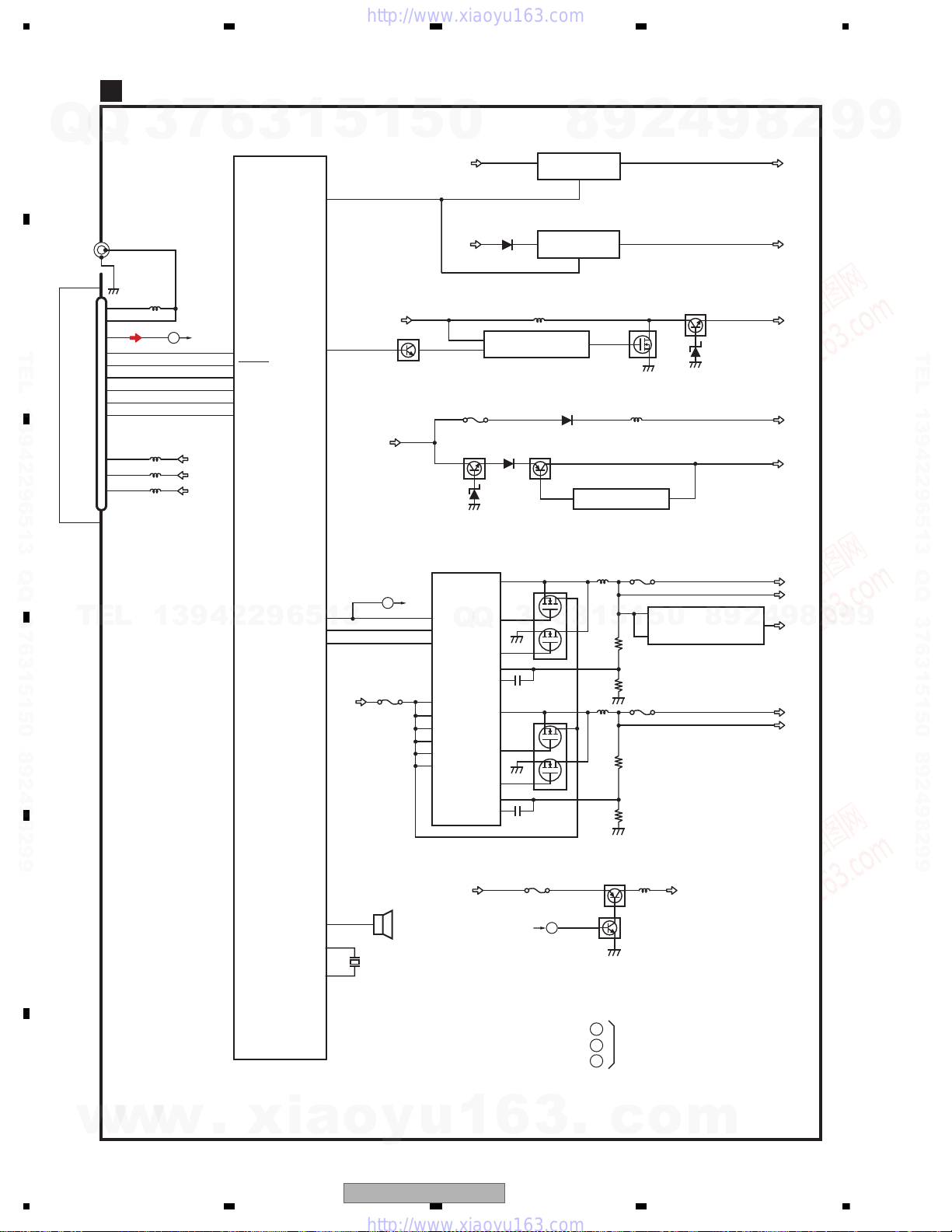
1234
1234
C
D
F
A
B
E
MOTHER PCB(2/2)
A
7
JA401
1
2,3
AM_ANT
1
FM_ANT
3
LchSLTUN_L
23
5
CE2
6
CE1
8
CK
9
DI
10
DO
14
VCC
4
ROM_VDD
13
VDD_3.3
17
3
B
13942296513
Q
ANTENNA
Q
TEL 13942296513 QQ 376315150 892498299
U401
FM/AM TUNER UNIT
TEL
TO 1/2
SYS+B
VDD33
TUN33V
6
119
TUNSL
114
TUNPCE2
113
TUNPCE
117
TUNPCK
118
TUNPDO
116
TUNPDI
SYSTEM uCON
3
IC601(2/2)
PEG535A8
HIOUTCLK
1
SYSPW
VDCONT5
VDCONT8
DDCCLK
5
128
92
25
26
80
BUP_1
BUP_1
VDCNT5
1
DD8
C
P1201
5
Q1143
D/D CONVERTER
TO 1/2
26
27
34
7
8
5
10
3
41
0
BUP_1
SYSPW
DD5
SYSPW
IC1201
BD9013KV
EN1
Q
EN2
SYNC
VCC
VCCCL1
VCCCL2
CL1
CL2
EXTVCC
P1021
Q1001
3
7
OUTH1
Q
OUTL1
COMP1
OUTH2
OUTL2
COMP2
SW1
SW2
Vcc
OSC
FB1
FB2
SYS+B
8
IC1061
NJM2388F84
12
VIN VOUT
CONTROL
4
TUN3.3V
IC1081
NJM2886DL3-33
2
VIN VOUT
CONT
1
HIOUT12V
TK11840L
13
Q1201
12
3
15
21
22
48
Q1202
1
46
39
38
IC1141
Q1002
7
5
Out
PWVI
2
S-812C33AUA-C2N
1
3
6
9
4
VDD33V
IC1001
5
Q1142
P1202
1
P1203
2
1
5
3
4
Q1141
3
ACC33V
VIN
IC1401
8
0
S-1112B33MC-L6S
ON/OFF
9
9
2
VOUT
8
5
4
2
SYS+B
TUN33V
EV12
PWVI
VDD33
VD5
DD5
9
ACC33
VD8
DD8
8
9
2
9
9
TEL 13942296513 QQ 376315150 892498299
9
PWFL
TO 1/2
6
P1022
A
3
DD8
85
w
w
28
w
.
xia
BEEP
XOUT
20
22
XIN
o
AVH-P3100DVD/XN/UC
BZ601
BUZZER
X601
15MHz
y
u
1
MFLPW
.
A
B
C
Q1022
Q1021
TO 1/2
c
o
PWFL
m

5678
56
7
8
C
D
F
A
B
E
7
Q
Q
TEL 13942296513 QQ 376315150 892498299
3
6
3
1
5
1
5
0
8
9
2
4
9
8
2
9
9
TEL 13942296513 QQ 376315150 892498299
TEL
13942296513
Q
Q
3
7
6
3
1
5
1
5
0
8
9
2
4
9
8
2
9
9
w
w
w
.
xia
o
y
u
1
6
3
.
AVH-P3100DVD/XN/UC
c
o
m
29
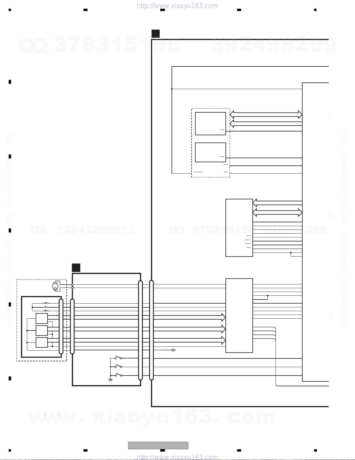
1234
1234
C
D
F
A
B
E
MA0-11
MDQ0-15
D0-15
VIDEO+AUD
IC1501
MN2DS0018M
S
S
USB_
TRC
TRC
TRC
T
S
E
F+
E+
D
COM
ST
CMD
ST
IR
E
TRC
NRES
A0-19
HWP(HW+),HWM(HW-)
HVP(HV+),HVM(HV-)
HUP(HU+),HUM(HU-)
HWP(HW+),HWM(HW-)
HVP(HV+),HVM(HV-)
HUP(HU+),HUM(HU-)
XRDNRES 28 214
NEXOE
NEXWE
70
NRES
I
I2
CP
I2
59
XCSSR
213
31
NEXCE
26
12
CE
OE
RESET
SDRAM
IC1480
K4S641632N-LC75
19
38
CS
CLK
XWE16 181
NWE
XCAS
DQM0
DQM1
17 188
NCAS
XRAS18 189
NRAS
XCSM 190
NCSM
20 193
BA0
21 197
BA1
BA0
BA1
15 179
DQM0
39
8
9
12
5
6
7
3
4
1
2
32
31
27
26
28
14
180
DQM1
LDQM
UDQM
MCK
VHALF
TD
FD
CRGDRV
MD
CONT1
CONT2
FOP
FOM
TOP
TOM
183
MCK
185
MCKI
V
CAS
RAS
WE
MOTOR DRIVER
IC1201
BD8231EFV
CTL1
CTL2
FG
FCO+
FCOTKO-
TKO+
FCIN
SLIN
VC
TKIN
LDIN
SPIN
W
HB
SL/LDOSL/LDO+
V
U
SLOPOUT
CN1201
CN101
CN701
CRG/LE+
COIL_U
17
18
16
6
3
4
5
9
8
7
HALL_BIASHALL_BIAS+
COIL_V
COIL_W
67
127
126
66
71
64
63
FG
CONT2
CONT1
12EJ
08EJ
HOME
62
MD
LDIN
CRGDRV
FD
TD
34
36
35
33
55
49
65
CRG/LE- 110
VHALF
FLASH 16M
IC1401
CWW1753
XCFS2
XCFS1
26
11 XWR1
CE
WE
IC1402
CWW1754
DVD CORE UNIT
C
VCC5
BR
GY
CRGCRG+
V COIL V
U COIL U
W COIL W
V
U
W
H- HALL BIASH+
H-
H+ HALL BIAS+
HOME
8SNS
DSCSNS
HOME
8cm
12cm(DSCSNS)
CONNECT PCB
SPINDLE MOTOR
LS1 MECHA UNIT
D
2
1
3
13
16
15
14
10
11
12
1
2
3
4
10
1
2
3
4
10
M
LOADING/CARRIAGE
MOTOR
HOME
S101
8cm
S102
12cm
S103
H3
H2
H1
7
Q
Q
3
6
3
1
5
1
5
0
TEL 13942296513 QQ 376315150 892498299
TEL
w
13942296513
w
w
.
xia
o
y
u
Q
Q
1
6
3
8
3
6
7
3
.
2
9
5
1
5
1
c
o
4
8
0
m
9
9
8
2
4
2
9
8
2
9
9
9
TEL 13942296513 QQ 376315150 892498299
9
30
AVH-P3100DVD/XN/UC
Loading...