

Page 1

19430-3FR-04
PNOZ XHCV
4
D Betriebsanleitung
4
GB Operating instructions
4
F Manuel d'utilisation
Sicherheitsbestimmungen
• Das Gerät darf nur von Personen installiert
und in Betrieb genommen werden, die mit
dieser Betriebsanleitung und den geltenden Vorschriften über Arbeitssicherheit
und Unfallverhütung vertraut sind.
Beachten Sie die VDE- sowie die örtlichen
Vorschriften, insbesondere hinsichtlich
Schutzmaßnahmen.
• Beim Transport, der Lagerung und im
Betrieb die Bedingungen nach EN 600682-6 einhalten (s. technische Daten).
• Durch Öffnen des Gehäuses oder eigenmächtige Umbauten erlischt jegliche Gewährleistung.
• Montieren Sie das Gerät in einen Schaltschrank; Staub und Feuchtigkeit können
sonst zu Beeinträchtigungen der Funktionen führen.
• Sorgen Sie an allen Ausgangskontakten
bei kapazitiven und induktiven Lasten für
eine ausreichende Schutzbeschaltung.
Bestimmungsgemäße Verwendung
Das Sicherheitsschaltgerät dient dem
sicherheitsgerichteten Unterbrechen eines
Sicherheitsstromkreises. Das Sicherheitsschaltgerät erfüllt Forderungen der
EN 60947-5-1, EN 60204-1 und VDE 01131 und darf eingesetzt werden in Anwendungen mit
• Not-Halt-Tastern
• Schutztüren
Das Gerät ist nicht für die Absicherung von
berührungslosen Verdeckungen geeignet, da
kein dynamischer Start möglich ist.
Safety Regulations
• The unit may only be installed and
operated by personnel who are familiar
with both these instructions and the current
regulations for safety at work and accident
prevention. Follow VDE and local
regulations especially as regards
preventative measures.
• Transport, storage and operating conditions
should all conform to
• Any guarantee is void following opening of
the housing or unauthorised modifications.
• The unit should be panel mounted,
otherwise dampness or dust could lead to
function impairment.
• Adequate protection must be provided on
all output contacts especially with
capacitive and inductive loads.
EN 60068-2-6
.
Authorised Applications
The safety relay provides a safety-related
interruption of a safety circuit. The safety
relay meets the requirements of EN 609475-1, EN 60204-1 and VDE 0113-1 and may
be used in applications with
• E-STOP pushbuttons
• Safety gates
The device is unsuitable for non-contact
barriers (e.g. light curtains) because a
dynamic start is not possible.
Conseils préliminaires
• La mise en oeuvre de l’appareil doit être
effectuée par une personne spécialisée en
installations électriques, en tenant compte
des prescriptions des différentes normes
applicables (NF, EN, VDE...) notamment
au niveau des risques encourus en cas de
défaillance de l’équipement électrique.
• Respecter les exigences de la norme
EN 60068-2-6 lors du transport, du
stockage et de l'utilisation de l'appareil.
• L’ouverture de l’appareil ou sa modification annule automatiquement la
garantie.
• L’appareil doit être monté dans une armoire; l’humidité et la poussière pouvant
entraîner des aléas de fonctionnement.
• Vérifiez que le pouvoir de coupure des
contacts de sortie est suffisant en cas de
circuits capacitifs ou inductifs.
Domaines d’utilisation
Le bloc logique de sécurité sert à
interrompre en toute sécurité un circuit de
sécurité. Le bloc logique de sécurité satisfait
aux exigences des normes EN 60947-5-1,
EN 60204-1 et VDE 0113-1 et peut être
utilisé dans des applications avec des
• poussoirs d'arrêt d'urgence
• protecteurs mobiles
L'appareil n'est pas adapté à la surveillance
de barrières immatérielles car une validation
dynamique n'est pas possible.
Gerätebeschreibung
Das Sicherheitsschaltgerät ist in einem
P-93-Gehäuse untergebracht. Es steht eine
Ausführung für den Betrieb mit 24 V
Gleichspannung zur Verfügung.
Merkmale:
• Relaisausgänge, rückfallverzögert:
2 Sicherheitskontakte (S), zwangsgeführt,
mit fester Rückfallverzögerung
• Statusanzeigen für Versorgungsspannung
und Schaltzustand aller Ausgangsrelais
• Anschluss für Not-Halt-Taster, Sicherheitsendschalter oder Schutztürschalter
und für externen Starttaster
• redundante Ausgangsschaltung
• ein- oder zweikanaliger Betrieb
• Rückführkreis zur Überwachung externer
Schütze
Das Schaltgerät erfüllt folgende Sicherheitsanforderungen:
• Die Sicherheitseinrichtung bleibt auch in
folgenden Fällen wirksam:
- Spannungsausfall
- Ausfall eines Bauteils
- Spulendefekt
- Leiterbruch
- Erdschluss
• Bei jedem Ein-Aus-Zyklus Überprüfung,
ob die Ausgangsrelais des Sicherheitsgerätes richtig öffnen und schließen
Description
The Safety Relay is enclosed in a P-93
housing. The version available is for 24
VDC operation only.
Features:
• Relay outputs, delay-on de-energised:
2 safety contacts (n/o), positive-guided
with fixed delay-on de-energisation
• LED for Operating Voltage and LED's for
switching positions of all output relays
• Connection for Safety limit switches,
Emergency stop buttons or safety gate
switches and for external reset buttons
• Output circuit is redundant
• Single or two channel operation
• Feedback control loop for monitoring
external contactors/relays
The relay complies with the following safety
requirements:
• The Emergency Stop Relay prevents
machine operation in the following cases:
- Power supply failure
- Component failure
- Coil defect in a relay
- Cable break
- Earth fault
• The correct opening and closing of the
Safety Gate limit switches and the safety
function output relays is tested
automatically in each on-off cycle
Description de l'appareil
Inséré dans un boîtier P-93, le bloc logique
de sécurité PNOZ XHCV est disponible
uniquement en 24 VCC
Caractéristiques :
• Contacts de sortie temporisés :
2 contacts à fermeture de sécurité (F),
temporisés à la retombée avec temporisation fixe
• LED d'indication présence tension et LEDs
de visualisation des relais internes
• Bornes de raccordement pour poussoirs
AU, fins de course de sécurité ou
interrupteurs de position et poussoir de
validation externe.
• Sorties redondantes.
• Commande par un ou deux canaux.
• Boucle de retour pour l'auto-contrôle de
contacteurs externes.
Le relais répond aux exigences suivantes :
• La sécurité est garantie, même dans les
cas suivants :
- Défaillance tension
- Défaillance d'un composant
- Défaillance bobine
- Défaut soudure
- Défaut de masse
• Vérification à chaque mise en route du
bon fonctionnement des relais internes
- 1 -
Page 2
Funktionsbeschreibung
Das Schaltgerät PNOZ XHCV dient dem
sicherheitsgerichteten Unterbrechen eines
Sicherheitsstromkreises. Nach Anlegen der
Versorgungsspannung leuchtet die LED
"Power".
S14 sowie
Relais K3 in Wirkstellung.
• Eingangskreis geschlossen (z. B. Not-
• Eingangskreis wird geöffnet (z. B. Not-
Bevor das Gerät erneut gestartet werden
kann, muss die Verzögerungszeit abgelaufen und alle Not-Halt- und Sicherheitskontakte müssen wieder geschlossen sein.
Bei geschlossenem Startkreis S13-
geöffnetem Eingangskreis geht
Halt-Taster nicht betätigt) Relais K1 und
K2 gehen über die Schließer K3.1 und
K3.2 in Wirkstellung und halten sich selbst
über K1.1 bzw. K2.1. Die Statusanzeigen
für "CH.1" und "CH.2" leuchten. Die
Sicherheitskontakte 37-38/47-48 sind
geschlossen.
Halt-Taster betätigt):
Nach Ablauf der fest eingestellten
Verzögerungszeit fallen die Relais K1 und
K2 zurück. Die Sicherheitskontakte 37-38
und 47-48 öffnen und die LED "CH.1" und
"CH.2" erlöschen.
Function Description
The relay PNOZ XHCV provides a safetyoriented interruption of a safety circuit.
When the operating voltage is supplied the
LED "Power" is illuminated.
When the reset circuit S13 - S14 is closed
and the input circuit is opened, relay K3
energises.
• Input circuit closed (e.g. Emergency Stop
Button not activated): Relays K1 and K2
energise via the N/O K3.1 and K3.2 and
latch via K1.1/K2.1. The status indicators
for "CH.1" and "CH.2" illuminate. The
safety contacts (37-38/47-48) are closed.
• Input Circuit is opened (e.g. Emergency
Stop is pressed):
Following the delay-on de-energisation
period, relays K1 and K2 de-energise. The
safety contacts 37-38 and 47-48 opens
and the LED "CH.1" and "CH.2"
extinguish.
The unit may only be reset once the delayon-de-energisation period has lapsed and all
E-Stop and safety contacts are closed.
Description du fonctionnement
Le relais PNOZ XHCV assure de façon
sure, l’ouverture d’un circuit de sécurité.
A la mise sous tension du relais (A1-A2), la
LED "Power" s'allume. Si le circuit de
réarmement S13-S14 est fermé et les
canaux d’entrée ouverts, le relais K3 colle.
• Fermeture des canaux d’entrée T11, T12
& T22 (par ex. AU non actionné) : les
relais K1 et K2 collent par l’intermédiaire
des contacts K3.1 et K3.2 et
s’automaintiennent par K1.1 et K2.1. Les
LEDs "CH.1" et " CH.2" s'allument. Les
contacts de sécurité (37-38/47-48) sont
fermés.
• Circuits d'entrée ouverts (poussoir AU
actionné) :
Au bout de la temporisation affichée, les
relais K1 et K2 retombent. Les contacts de
sécurité 37-38/47-48 s'ouvrent et les LEDs
"CH.1" et "CH.2" s'éteignent.
Les canaux d'entrée doivent être refermés et
la temporisation écoulée avant de pouvoir
réarmer à nouveau le relais.
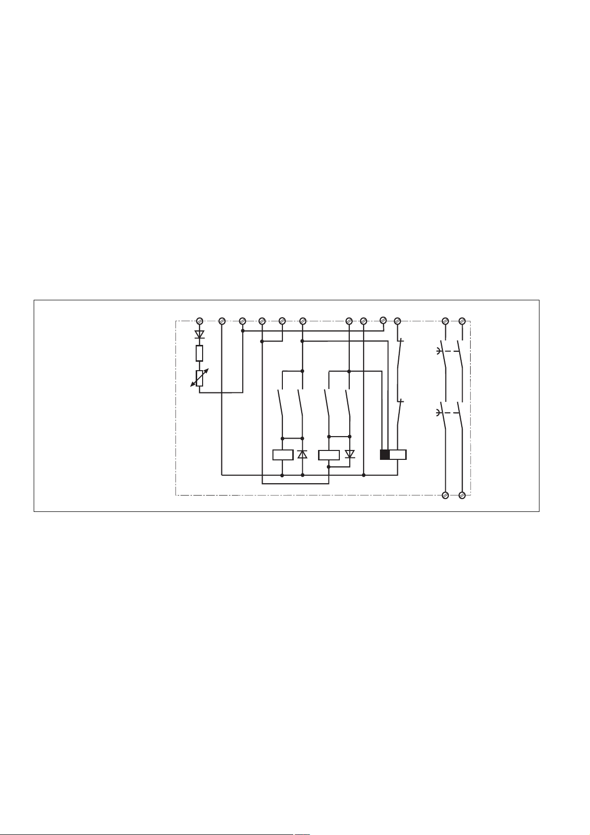
A1 (L+)
Fig. 1: Innenschaltbild/
Internal Wiring Diagram/
Schéma de principe
Betriebsarten:
• Einkanaliger Betrieb:
Eingangsbeschaltung nach VDE 0113
Teil 1 und EN 60204-1, keine Redundanz
im Eingangskreis, Erdschlüsse im
Tasterkreis werden erkannt.
• Zweikanaliger Betrieb: Redundanter Eingangskreis, Erdschlüsse im Tasterkreis
und Querschlüsse zwischen den Tasterkontakten werden erkannt.
• Automatischer Start: Gerät ist aktiv, sobald
Eingangskreis geschlossen ist.
• Manueller Start: Gerät ist erst dann aktiv,
wenn ein Starttaster (S13-S14) betätigt
wird. Dadurch ist eine automatischer Start
des Schaltgeräts nach Spannungsausfall
und -wiederkehr ausgeschlossen.
• Kontaktvervielfachung und -verstärkung
durch Anschluss von externen Schützen.
A2 (L-)
S11
S31
S12
K3.1
K1.1
K1 K2
S32
K2.1
S22
K3.2
Operating Modes
• Single-channel operation: Input wiring
according to VDE 0113 part 1 and
EN 60204-1, no redundancy in the input
circuit, earth faults are detected in the
emergency stop circuit.
• Two-channel operation: Redundancy in
the input circuit, earth faults in the
Emergency Stop circuit and shorts across
the emergency stop push button are also
detected.
• Automatic reset: Unit is active as soon as
the input circuit is closed.
• Manual reset: Unit is only active when a
reset button (S13-S14) has been pressed.
Automatic reset following a loss/return of
supply voltage is thereby prevented.
• Increase in the number of available
contacts by connection of external
contactors/relays.
S21
S13
S14
K1.2
K2.2
K3
37 47
K1
K2
38 48
Modes de fonctionnement
• Commande par 1 canal : conforme aux
prescriptions de la EN 60 204-1, pas de
redondance dans le circuit d’entrée, la
mise à la terre du circuit d’entrée est
détectée
• Commande par 2 canaux: circuit d’entrée
redondant, la mise à la terre et les courtscircuits entre les contacts sont détectés.
• Réarmement automatique : le relais est
activé dès la fermeture des canaux
d’entrée.
• Réarmement manuel : le relais n’est activé
qu’après une impulsion sur un poussoir de
validation (S13-S14). Un réarmement
automatique du relais après une coupure
d’alimentation est ainsi impossible.
• Augmentation du nombre de contacts ou
du pouvoir de coupure par l’utilisation de
contacteurs externes.
Montage
Das Sicherheitsschaltgerät muss in einen
Schaltschrank mit einer Schutzart von mind.
IP54 eingebaut werden. Zur Befestigung auf
einer Normschiene dient ein Rastelement auf
der Rückseite des Geräts.
Installation
The safety relay must be panel mounted
(min. IP54). There is a notch on the rear of
the unit for DIN-Rail attachment.
- 2 -
Montage
Le relais doit être monté en armoire ayant un
indice de protection mini IP54. Sa face
arrière permet un montage sur rail DIN.
Page 3

Inbetriebnahme
Beachten Sie bei der Inbetriebnahme:
• Auslieferungszustand: Brücke zwischen
S11-S12 (Eingangskreis zweikanalig).
• Max. Leitungslängen (Eingangskreis):
Voraussetzungen:
Leiterquerschnitt: 2 x 1,5 mm
Kapazität: 150 nF/km
Widerstand: 28 Ohm/km
Temperatur: +25 °C
30 Ohm Leitungswiderstand: 1 km
Werte gelten für zweikanalige Beschaltung, für einkanalige Beschaltung gelten
die halben Werte.
• Leitungsmaterial aus Kupferdraht mit einer
Temperaturbeständigkeit von 60/75 °C
verwenden.
• Das Anzugsdrehmoment der Schrauben
auf den Anschlussklemmen darf max.
0,6 Nm betragen.
• Sorgen Sie beim Anschluss von magnetisch wirkenden, auf Reedkontakten
basierenden Näherungsschaltern dafür,
dass der max. Einschaltspitzenstrom (am
Eingangskreis) den Näherungsschalter
nicht überlastet.
• Angaben im Kapitel „Technische Daten“
unbedingt einhalten.
Ablauf:
• Versorgungsspannung an Klemmen A1
und A2 anlegen.
• Startkreis:
- Automatischer Start: S13-S14 brücken.
- Manueller Start: Taster an S13-S14
anschließen
• Eingangskreis:
- Einkanalig: S21-S22 und S31-S32
brücken. Öffnerkontakt von Auslöseelement an S11 und S12 anschließen.
- Zweikanalig: S11-S12 brücken.
Öffnerkontakt von Auslöseelement an
S21-S22 und S31-S32 anschließen.
•
Rückführkreis:
Externe Schütze in Reihe zu Startkreis
S13-S14 anschließen.
Die Sicherheitskontakte sind aktiviert (geschlossen). Die Statusanzeige für "CH.1"
und "CH. 2" leuchten. Das Gerät ist betriebsbereit.
Wird der Eingangskreis geöffnet, so öffnen
nach Ablauf der Verzögerungszeit die
Sicherheitskontakte 37-38/47-48 und die
Statusanzeigen "CH.1" und "CH.2" erlöschen.
Wieder aktivieren
• Eingangskreis schließen.
• Bei manuellem Start zusätzlich Taster
zwischen S13 und S14 betätigen.
Die Statusanzeigen leuchten wieder, die
Sicherheitskontakte sind geschlossen.
Anwendung
In Fig. 2 ... Fig. 9 sind Anschlußbeispiele für
NOT-AUS-Beschaltung mit automatischem
und manuellem Start, Schutztüransteuerungen sowie Kontaktvervielfachung durch
externe Schütze.Bitte beachten Sie:
• Fig. 2 und 8:
Spannungsausfall und -wiederkehr
automatisch. Verhindern Sie einen
unerwarteten Wiederanlauf durch externe
Schaltungsmaßnahmen.
• Fig. 3, 4 und 5, 6:
keine Verbindung S13-S14
Das Gerät startet bei
Operation
Please note for operation:
• Unit delivered with a bridge between S11S12 (2-channel input circuit).
• Cable runs: (Input Circuit)
Requirements:
2
Cable cross section 2 x 1.5 mm
Capacity 150 nF/km
Resistance 28 Ohm/km
Temperature + 25 °C
Max. length (Input circuit):
30 Ohm cable resistance: 1 km
Values for two-channel wiring; For singlechannel wiring, values should be halved.
• Use copper wiring that will withstand
60/75 °C
• Tighten terminals to 0.6 Nm.
• When connecting magnetically operated,
reed proximity switches, ensure that the
max. peak inrush current (on the input
circuit) does not overload the proximity
switch.
• Important details in the section "Technical
Data“ should be noted and adhered to.
To operate:
• Supply operating voltage:
Connect the operating voltage to terminals
A1 and A2
• Reset circuit:
- Automatic reset: Bridge S13-S14
- Manual reset: Connect button to S13-
S14
• Input circuit:
- Single-channel: Bridge S21-S22 and
S31-S32. Connect N/C contact from
safety switch (e.g. Emergency-Stop) to
S12 and S11.
- Two-channel: Bridge S11-S12. Connect
N/C contact from safety switch (e.g.
Emergency-Stop) to S21-S22 and S31S32.
• Feedback control loop:
Connect external relays/contactors in
series to reset circuit S13-S14.
The safety contacts are activated (closed).
The status indicators "CH.1" and "CH.2" are
illuminated. The unit is ready for operation.
If the input circuit is opened, the safety
contacts 37-38/47-48 open after the delayon-de-energisation period and the status
indicators "CH.1" and "CH.2" extinguish.
Reactivation
• Close the input circuit.
• For manual reset, close the input circuit
and press the button and release between
S13-S14.
The status indicators light up again, the
safety contacts are closed.
Application
In Fig. 2...Fig. 9 are connection examples for
Emergency Stop wiring with automatic and
manual reset. Safety gate controls as well
as contact expansion via external
contactors.
• Fig. 2 and 8: The device starts
automatically after loss of power. You
should prevent an unintended start-up by
using external circuitry measures.
• Fig. 3, 4 and 5, 6: S13-S14 not connected
Mise en oeuvre
Remarques préliminaires :
• Pontages présents à la livraison: S11-S12
(commande par 2 canaux).
• Longueurs de câblage max. (circuits
d’entrée) Préalable:
2
câble: 2 x 1,5 mm
capacité : 150 nF/Km
résistivité : 28 Ohm/Km
température : 25 °C
résistivité max. 30 Ohm : 1Km
Valeurs indiquées pour une commande
par 2 canaux. En cas de commande par 1
canal, la moitié des valeurs est valable.
• Utiliser uniquement des fils de cablâge en
cuivre 60/75 °C.
• Le couple de serrage sur les bornes de
racordement ne doît pas dépasser
0,6 Nm.
• Lors du raccordement de détecteurs de
proximité magnétiques, basés sur des
contacts Reed, veuillez vous assurer que
le courant de crête max. à la mise sous
tension (sur le circuit d'entrée) ne
surcharge pas les détecteurs de
proximité.
• Respecter les données indiquées dans le
chap. „Caractéristiques techniques“.
Mise en oeuvre :
• Tension d’alimentation:
amener la tension d’alimentation sur A1
et A2
• Circuit de réarmement:
- réarmement automatique: pontage des
bornes S13-S14
- réarmement manuel : câblage d'un
poussoir sur S13-S14
• Circuits d’entrée:
- Commande par 1 canal : câblage du
contact à ouverture entre S11-S12,
pontage entre S21-S22 et S31-S32
- Commande par 2 canaux: câblage des
contacts à ouverture entre S21-S22 et
S31-S32, pontage entre S11-S12
• Boucle de retour:
câbler les contacts des contacteurs
externes en série dans le circuit de
réarmement S13-S14.
Les contacts de sécurité se ferment. Les
LEDs "CH.1" et "CH.2" sont allumées.
L’appareil est prêt à fonctionner.
Si le circuit d’entrée est ouvert, les contacts
de sécurité 37-38/47-48 retombent a la fin de
la temporisation et les LEDs "CH.1" et
"CH.2" s’éteignent.
Remise en route :
• fermer le circuit d’entrée
• en cas de réarmement manuel, fermer le
circuit d’entrée et appuyer le poussoir de
validation S13-S14.
Les affichages d'état s'allument à nouveau.
Les contacts de sécurité sont fermées.
Utilisation
Les figures 2 à 9 représentent les différents
câblages possibles du PNOZ XHCV à savoir
: poussoir AU avec réarmement automatique
ou manuel, interrupteurs de position et
augmentation du nombre des contacts de
sécurité par contacteurs externes.
• Fig. 2 et 8: L’appareil se réarme
automatiquement après une coupure et
une remise sous tension. Evitez tout
risque de redémarrage par un câblage
externe approprié.
• Fig. 3, 4 et 5, 6:
pas de câblage sur S13-S14
2
- 3 -
Page 4

S12
S14
S13
S11
S21
S32
S22
S1
S2
S31
• Fig. 7: Automatischer Start bei Schutztürsteuerung: Das Gerät ist bei geöffneter
Schutztür über den Startkreis S13-S14
startbereit. Nach Schließen der Eingangskreise S11-S12, S21-S22 und S31-S32
werden die Sicherheitskontakte geschlossen.
• Fig. 7: Automatic reset with safety gate
control: with the safety gate open the unit
is ready for operation via reset circuit
S13-S14. After closing the safety input
circuit S11-S12, S21, S22 and S31-S32
the safety contacts will close.
• Fig. 7: Réarmement automatique en cas
de surveillance protecteur: lorsque le
protecteur est ouvert, le circuit S13-S14 se
ferme et le relais est prêt à fonctionner.
Dès la fermeture des canaux d'entrée
S11-S12, S21-S22 et S31-S32, les
contacts de sortie du relais se ferment.
S11 S31
S1
S12
S32
S21
S22
S13
S14
Fig. 2: Eingangskreis einkanalig, automat.
Start/Single-channel input circuit,
automatic reset/Commande par 1 canal,
validation automatique
S11
S12
S21
S1
S22
S31
S32
S13
S3
S14
Fig. 5: Schutztürsteuerung einkanalig,
manueller Start/Single-channel safety gate
control, manual reset/Surveillance de
protecteur, commande par 1 canal,
réarmement manuel
S11 S31
S1
S12
S32
S21
S22
S13
S3
S14
Fig. 3: Eingangskreis einkanalig, manueller
Start/Single-channel input circuit, manual
reset/Commande par 1 canal, réarmement
manuel
S13
S11
S21
S1
S22
S3
S31
S2
S32
S12
S14
Fig. 6: Schutztürsteuerung zweinkanalig,
manueller Start/Two-channel safety gate
control, manual reset/Surveillance de
protecteur, commande par 2 canaux,
réarmement manuel
S11
S12
S13
S3
S14
S31
S21
S1
S32
S22
Fig. 4: Eingangskreis zweikanalig,
manueller Start/Two-channel input circuit,
manual reset/Commande par 2 canaux,
réarmement manuel
Fig. 7: Schutztürsteuerung zweikanalig,
automatischer Start/Two channel safety
gate control, automatic reset/Surveillance
de protecteur, commande par 2 canaux,
validation automatique
1L1
K6
K7
K8
K5
1L2
S13
S14
K5
K6 K8
47
37
48
38
K7
Fig. 8: Anschlussbeispiel für externe
Schütze, einkanalig, automatischer Start/
Connection example for external
contactors/
relays, single-channel,
1L1
K7
K6
K5
K8
S13
K5
1L2
S3
S14
37
38
K6 K8
47
48
K7
Fig. 9: wie Fig. 8 mit manuellem Start/
connection for contactors/relays and
manual reset/comme Fig. 8 avec
réarmement manuel
automatic reset/Branchement contacteurs
externes, commande par 1 canal,
validation automatique
betätigtes Element/Switch
activated/élément actionné
Tür nicht geschlossen/Gate
open/porte ouverte
Tür geschlossen/Gate closed/
porte fermée
S1/S2: Not-Halt- bzw. Schutztürschalter/Emergency Stop Button, Safety Gate Limit Switch/Poussoir AU, détecteurs de position
S3: Starttaster/Reset button/Poussoir de réarmement
- 4 -
Page 5

Fehler - Störungen
• Erdschluss
Eine elektronische Sicherung bewirkt das
Öffnen der Ausgangskontakte. Nach
Wegfall der Störungsursache und
Einhalten der Versorgungsspannung ist
das Gerät nach ca. 5 s wieder betriebsbereit.
• Fehlfunktionen der Kontakte: Bei verschweißten Kontakten ist nach Öffnen des
Eingangskreises keine neue Aktivierung
möglich.
• LED "Power" leuchtet nicht: Kurzschluss
oder Versorgungsspannung fehlt
Faults
• Earth fault
An electronic fuse causes the output
contacts to open with fault currents.
Once the cause of the fault is removed
and the supply voltage applied, the unit is
ready for operation after 5 s.
• Contact failure: In the case of welded
contacts, no further activation is possible
following an opening of the input circuit.
• LED "Power" is not illuminated if shortcircuit or the supply voltage is lost.
Erreurs - Défaillances
• Défaut de masse
Un fusible électronique entraîne
l’ouverture des contacts de sortie.
L’appareil est à nouveau prêt à
fonctionner env. 5 sec. après la
disparition du défaut.
• Défaut de fonctionnement des contacts de
sortie: en cas de soudage d’un contact
lors de l’ouverture du circuit d’entrée, un
nouvel réarmement est impossible.
• LED "Power" éteinte: tension
d'alimentation non présente ou courtcircuit interne.
Technische Daten
Elektrische Daten
Versorgungsspannung U
Spannungstoleranz U
Leistungsaufnahme bei U
Spannung und Strom an
(S11-S12)
(S21-S22, S31-32)
(S13-S14)
Anzahl der Ausgangskontakte
Sicherheitskontakte (S)
Gebrauchskategorie nach
EN 60947-4-1
EN 60947-5-1
(DC13: 6 Schaltspiele/Min.)
Kontaktmaterial
Kontaktabsicherung extern
EN 60947-5-1 (IK = 1 kA)
Schmelzsicherung
Sicherungsautomat,
Charakteristik B/C
Konventioneller thermischer Strom
Max. Gesamtleitungswiderstand
R
Imax
Eingangskreise
einkanalig
zweikanalig ohne Querschluss-
erkennung
zweikanalig mit
Querschlusserkennung
Min. Eingangswiderstand im
Einschaltmoment
Zeiten
Einschaltverzögerung
automatischer Start
automatischer Start nach Netz-Ein
Rückfallverzögerung
bei Not-Halt
bei Netzausfall
Wiederbereitschaftszeit bei max.
Schaltfrequenz 1/s
nach Not-Halt
nach Netzausfall
Verzögerungszeit
Zeitgenauigkeit
Gleichzeitigkeit Kanal 1 und 2
Überbrückung bei Spannungs-
einbrüchen
Umweltdaten
EMV
Schwingungen nach EN 60068-2-6
Frequenz
Amplitude
B
B
B
Technical details
Electrical data
Supply voltage U
Voltage tolerance U
Power consumption at U
Voltage and current at
(S11-S12)
(S21-S22, S31-32)
(S13-S14)
Number of output contacts
Safety contacts (S)
Utilization category in accordance with
EN 60947-4-1
EN 60947-5-1
(DC13: 6 cycles/min)
Contact material
External contact fuse protection
EN 60947-5-1 (IK = 1 kA)
blow-out fuse
Circuit breaker,
characteristic B/C
Conventional thermal current
Max. overall cable resistance R
input circuits
single-channel
dual-channel without detection of
shorts across contacts
dual-channel with detection of
shorts across contacts
Min. input resistance in the starting
torque
Times
Switch-on delay
Automatic reset
Automatic reset after power-ON
Delay-on de-energisation
at E-STOP
with power failure
Recovery time at max. switching
frequency 1/s
after E-STOP
after power failure
Delay-on De-Energisation
Time accuracy
Simultaneity channel 1 and 2
Supply interruption before
de-energisation
Environmental data
EMC
Vibration to EN 60068-2-6
Frequency
Amplitude
B
B
B
lmax
Caractéristiques techniques
Données électriques
Tension d’alimentation U
Plage de la tension d'alimentation U
Consommation pour U
Tension et courant sur
(S11-S12)
(S21-S22, S31-32)
(S13-S14)
Nombre de contacts de sortie
Contacts de sécurité (F)
Catégorie d’utilisation selon
EN 60947-4-1
EN 60947-5-1
(DC13: 6 manoeuvres/min)
Matériau contact
Protection des contacts externe
EN 60947-5-1 (IK = 1 kA)
fusible
Disjoncteur,
caractéristique B/C
Courant thermique conventionnel
Résistance max. de l'ensemble du
câblage R
circuit d’entrée
lmax
commande par 1 canal
Commande par 2 canaux sans
détection des court-circuits
Commande par 2 canaux avec
détection des court-circuits
Résistance d'entrée min. au moment
de la mise en marche
Temporisations
Temps de réarmement
Réarmement automatique
Réarmement automatique après
mise sous tension
Temps de retombée
en cas d'arrêt d'urgence
en cas de coupure d'alimentation
Temps de remise en service pour une
fréquence de commutation max. de 1/s
après un arrêt d'urgence
après une coupure d'alimentation
Temps de retombée t
Précision du temps
Désynchronisme canal 1 et 2
Tenue aux micro-coupures
Données sur l'environnement
CEM
Vibrations selon EN 60068-2-6
Fréquences
Amplitude
B
B
v
24 V DC
-15 % ... +10 %
B
5 W
24 V DC, 200 mA
24 V DC, 100 mA
24 V DC, 50 mA
2
AC1: 240 V/0,2... 10 A/
2400 VA
DC1: 24 V/0,2...10 A/
240 W
AC15: 230 V/5 A;
DC13: 24 V/7 A
AgNi10
10 A link/quick acting/rapide
6 A träge/slow acting/
normal
24 V AC/DC, 6 A
10 A
30 Ohm
60 Ohm
5 Ohm
19 Ohm
typ. 250 ms, max. 350 ms
typ. 250 ms, max. 350 ms
typ.: 700 ms, max.: 1 s
typ.: 700 ms, max.: 1 s
50 ms + tv
50 ms + tv
0,7 s
-43% / +43%
120 ms
35 ms
EN 50081-1, EN 61000-6-2
10-55 Hz
0,35 mm
- 5 -
Page 6

Klimabeanspruchung
Luft- und Kriechstrecken nach
Bemessungsisolationsspannung
Bemessungsstoßspannungsfestigkeit
Umgebungstemperatur
Lagertemperatur
Schutzart
Einbauraum (z. B. Schaltschrank)
Gehäuse
Klemmenbereich
Mechanische Daten
Gehäusematerial
Gehäuse
Front
Querschnitt des Außenleiters
Anzugsdrehmoment für
Anschlussklemmen (Schrauben)
Abmessungen H x B x T
Einbaulage
Gewicht
Climate Suitability
Airgap Creepage in accordance with
Rated insulation voltage
Rated impulse withstand voltage
Ambient temperature
Storage temperature
Protection type
Mounting (eg. cabinet)
Housing
Terminals
Mechanical data
Housing material
Housing
Front
Cable cross section
Torque setting for connection
terminal screw
Dimensions H x W x D
Fitting Position
Weight
Conditions climatiques
Cheminement et claquage selon
Tension assignée d'isolement
Tension assignée de tenue aux chocs
Température d’utilisation
Température de stockage
Indice de protection
Lieu d'implantation (ex. armoire)
Boîtier
Bornes
Données mécaniques
Matériau du boîtier
Boîtier
Face avant
Capacité de raccordement
Couple de serrage (bornier)
Dimensions H x P x L
Position de travail
Poids
EN 60068-2-3
EN 60947-1
250 V
4 kV
-10 ... + 55 °C
-40 ... +85 °C
IP54
IP40
IP20
PPO UL 94 V0
ABS UL 94 V0
Einzelleiter oder
mehrdrähtiger Leiter mit
Aderendhülse/single-core
or multicore with
crimp connectors/fils
séparés ou fils groupés
avec embout:
2 x 1,5 mm2 oder/or/ou
1 x 2,5 mm
2
0,6 Nm
87 x 112,5 x 121 mm
beliebig/any/indifférente
800 g
Um ein Versagen der Geräte zu verhindern,
ist an allen Ausgangskontakten für eine
ausreichende Funkenlöschung zu sorgen.
Bei kapazitiven Lasten sind eventuelle
To prevent failure of the unit, all output
contacts should be fused adequately. With
capacitive loads, possible current peaks are
to be watched for.
Stromspitzen zu beachten.
Bestelldaten/Order reference/Caractéristiques
Typ/
Type/
Type
PNOZ XHCV
Merkmale/
Features/
Caractéristiques
24 V DC
Prévoir un dispositif d'extinction d'arc sur les
contacts de sortie pour éviter un éventuel
disfonctionnement du relais. Tenir compte
des pointes d'intensités en cas de charge
capacitive.
Klemmen/
Terminals/
Borniers
Schraubklemmen/screw terminals/borniers à vis
Bestell-Nr./
Order no./
Référence
774 560
- 6 -
Page 7

Abmessungen in mm (")/Dimensions in mm (")/Dimensions en mm (")
121 (4.76")
75 (2.95")
87 (3.42")
EG-Konformitätserklärung:
Diese(s) Produkt(e) erfüllen die Anforderungen der Richtlinie 2006/42/EG über
Maschinen des europäischen Parlaments
und des Rates.
Die vollständige EG-Konformitätserklärung
finden Sie im Internet unter www.pilz.com
Bevollmächtigter: Norbert Fröhlich,
Pilz GmbH & Co. KG, Felix-Wankel-Str. 2,
73760 Ostfildern, Deutschland
112,5 (4.41")
EC Declaration of Conformity:
This (these) product(s) comply with the
requirements of Directive 2006/42/EC of the
European Parliament and of the Council on
machinery.
The complete EC Declaration of Conformity
is available on the Internet at www.pilz.com
Authorised representative: Norbert Fröhlich,
Pilz GmbH & Co. KG, Felix-Wankel-Str. 2,
73760 Ostfildern, Germany
Déclaration de conformité CE :
Ce(s) produit(s) satisfait (satisfont) aux
exigences de la directive 2006/42/CE
relative aux machines du Parlement
Européen et du Conseil.
Vous trouverez la déclaration de conformité
CE complète sur notre site internet
www.pilz.com
Représentant : Norbert Fröhlich,
Pilz GmbH & Co. KG, Felix-Wankel-Str. 2,
73760 Ostfildern, Allemagne
- 7 -
Page 8

Technischer Support
+49 711 3409-444 +49 711 3409-444
...
In vielen Ländern sind wir durch
unsere Tochtergesellschaften und
Handelspartner vertreten.
Nähere Informationen entnehmen
Sie bitte unserer Homepage oder
nehmen Sie Kontakt mit unserem
Stammhaus auf.
Technical support
... ...
In many countries we are
represented by our subsidiaries
and sales partners.
Please refer to our Homepage
for further details or contact our
headquarters.
- 8 -
Assistance technique
+49 711 3409-444
Nos filiales et partenaires
commerciaux nous représentent
dans plusieurs pays.
Pour plus de renseignements,
consultez notre site internet ou
contactez notre maison mère.
www
www.pilz.com
Pilz GmbH & Co. KG
Felix-Wankel-Straße 2
73760 Ostfildern, Germany
Telephone: +49 711 3409-0
Telefax: +49 711 3409-133
E-Mail: pilz.gmbh@pilz.de
Originalbetriebsanleitung/Original instructions/Notice originale
19430-3FR-04, 2010-08 Printed in Germany
 Loading...