

Page 1

_Name_Bookmark2_
_Name_Bookmark2_
PNOZ m0p
PNOZmulti Modular Safety System
Operating Manual — No. 1002053-EN-03
Page 2

_Name_Bookmark2_
This document is a translation of the original document.
All rights to this documentation are reserved by Pilz GmbH & Co. KG. Copies may be made
for internal purposes.
Suggestions and comments for improving this documentation will be gratefully received.
Pilz®, PIT®, PMI®, PNOZ®, Primo®, PSEN®, PSS®, PVIS®, SafetyBUS p®, SafetyEYE®,
SafetyNET p®, the spirit of safety® are registered and protected trademarks of
Pilz GmbH & Co. KG in some countries.
SD means Secure Digital.
Page 3

Contents
Contents
Contents Page
Chapter 1 Introduction
1.1 Validity of documentation 1-1
1.1.1 Retaining the documentation 1-1
1.2 Overview of documentation 1-2
1.3 Definition of symbols 1-3
Chapter 2 Overview
2.1 Unit structure 2-1
2.1.1 Scope of delivery 2-1
2.1.2 Unit features 2-1
2.1.3 Chip card 2-2
2.2 Front view 2-3
2.2.1 PNOZ m0p 2-3
2.2.2 PNOZ m0p ETH 2-3
2.2.3 Key 2-4
Chapter 3 Safety
3.1 Intended use 3-1
3.1.1 System requirements 3-1
3.2 Safety regulations 3-2
3.2.1 Use of qualified personnel 3-2
3.2.2 Warranty and liability 3-2
3.2.3 Disposal 3-2
3.2.4 For your safety 3-3
Chapter 4 Function description
4.1 Unit properties 4-1
4.1.1 Integrated protection mechanisms 4-1
4.1.2 Function description 4-1
4.1.2.1 Operation 4-1
4.1.2.2 Block diagram 4-2
4.1.2.3 Diagnostics 4-2
4.1.2.4 Cascading 4-2
4.1.2.5 Safety mat, muting 4-3
4.1.3 Interfaces 4-3
Chapter 5 Installation
5.1 General installation guidelines 5-1
5.1.1 Dimensions 5-2
5.2 Connecting the base unit and expansion
modules
5-3
Pilz GmbH & Co. KG, Felix-Wankel-Straße 2, 73760 Ostfildern, Germany
Telephone: +49 711 3409-0, Telefax: +49 711 3409-133, E-Mail: pilz.gmbh@pilz.de
1
Page 4

Contents
Chapter 6 Commissioning
6.1 General wiring guidelines 6-1
6.2 Ethernet interfaces (only PNOZ m0p ETH) 6-2
6.2.1 RJ45 interfaces ("Ethernet") 6-2
6.2.2 Requirements of the connection cable and
connector
6.2.3 Interface configuration 6-2
6.2.4 RJ45 connection cable 6-3
6.2.5 Process data exchange 6-3
6.3 Preparing for operation 6-5
6.3.1 Function test during commissioning 6-5
6.3.2 Commissioning the PNOZmulti safety system for the first time
6.3.2.1 Load project from chip card 6-5
6.3.2.2 Load project via integrated interface 6-6
6.3.3 Download modified project to the
PNOZmulti safety system
6.3.3.1 Load modified project from chip card 6-6
6.3.3.2 Load modified project via integrated interface
6.3.4 Connection 6-7
6.4 Connection example 6-9
6-2
6-5
6-6
6-6
Chapter 7 Operation
7.1 Messages 7-1
7.1.1 Display elements for device diagnostics 7-1
7.1.2 Display elements for the Ethernet connection (only PNOZ m0p ETH)
7.2 Reset Ethernet connection settings 7-3
Chapter 8 Technical details
8.1 Technical details 8-1
8.2 Service life graph of output relays 8-5
8.3 Maximum capacitive load C (μF) with load
current I (mA) at the semiconductor outputs
8.4 Order reference 8-7
7-2
8-6
Pilz GmbH & Co. KG, Felix-Wankel-Straße 2, 73760 Ostfildern, Germany
2
Telephone: +49 711 3409-0, Telefax: +49 711 3409-133, E-Mail: pilz.gmbh@pilz.de
Page 5

1 Introduction
1.1 Validity of documentation
11000IntroductionIntroduction1-1.1Validity of docume ntation1100Validity of documenta tion1-Einf Gltigkeit der Dokumentation
This documentation is valid for the product PNOZ m0p. It is valid until
Einf Einleitung
1.1.1 Retaining the documentation
Retaining the documentation1-Einf Aufbewahren
new documentation is published.
This operating manual explains the function and operation, describes
the installation and provides guidelines on how to connect the product .
This documentation is intended for instruction and should be retained
for future reference.
Pilz GmbH & Co. KG, Felix-Wankel-Straße 2, 73760 Ostfildern, Germany
Telephone: +49 711 3409-0, Telefax: +49 711 3409-133, E-Mail: pilz.gmbh@pilz.de
1-1
Page 6

1 Introduction
1.2 Overview of documentation
1.2Overview of documentation1200Overview of documentation1-Einf_Uebersicht_über_die_Doku_6_Inbetriebnahme
1 Introduction
The introduction is designed to familiarise you with the contents, structure and specific order of this manual.
2 Overview
This chapter provides information on the product's most important features.
3 Safety
This chapter must be read as it contains important information on intended use.
4 Function Description
This chapter describes the product's mode of operation.
5 Installation
This chapter explains how to install the product.
6 Commissioning
This chapter describes the product's commissioning and wiring.
7 Operation
This chapter describes how to operate the product and gives tips in the
case of a fault.
8 Technical Details
This chapter contains the product's technical details and order reference.
1-2
Pilz GmbH & Co. KG, Felix-Wankel-Straße 2, 73760 Ostfildern, Germany
Telephone: +49 711 3409-0, Telefax: +49 711 3409-133, E-Mail: pilz.gmbh@pilz.de
Page 7
1 Introduction
1.3 Definition of symbols
1.3Definition of symbols1300Definition of symbols1-Einfhrung Zeichen
Information that is particularly important is identified as follows:
DANGER!
This warning must be heeded! It warns of a hazardous situation
that poses an immediate threat of serious injury and death and
indicates preventive measures that can be taken.
WARNING!
This warning must be heeded! It warns of a hazardous situation
that could lead to serious injury and death and indicates preventive measures that can be taken.
CAUTION!
This refers to a hazard that can lead to a less serious or minor
injury plus material damage, and also provides information on
preventive measures that can be taken.
NOTICE
This describes a situation in which the product or devices could
be damaged and also provides information on preventive measures that can be taken.
INFORMATION
This gives advice on applications and provides information on
special features, as well as highlighting areas within the text that
are of particular importance.
Pilz GmbH & Co. KG, Felix-Wankel-Straße 2, 73760 Ostfildern, Germany
Telephone: +49 711 3409-0, Telefax: +49 711 3409-133, E-Mail: pilz.gmbh@pilz.de
1-3
Page 8

1 Introduction
1-4
Pilz GmbH & Co. KG, Felix-Wankel-Straße 2, 73760 Ostfildern, Germany
Telephone: +49 711 3409-0, Telefax: +49 711 3409-133, E-Mail: pilz.gmbh@pilz.de
Page 9

2 Overview
2.1 Unit structure
22000OverviewOverview2-2.1Unit structure2100Unit structure2-
2.1.1 Scope of delivery
Scope of delivery2-Lieferumfang_Abschl_77 9 110_Basis_BA
2.1.2 Unit features
Unit features2-Gerätemerkmale_Verwendung
` Base unit PNOZ m0p
` Terminator 779 110
Verwendung/Bildunterschrift_multi_Basis
Geraetemerkmale_Zusatz BA Einleitung
Gertemerkmale PNOZ m0p
Using the product PNOZ m0p:
Base units from the PNOZmulti modular safety system
The product has the following features:
` Can be configured in the PNOZmulti Configurator
` Positive-guided relay outputs:
– 2 safety outputs
Depending on the application, up to PL e of EN ISO 13849-1 and
up to SIL CL 3 of EN IEC 62061
` Semiconductor outputs:
– 4 safety outputs
Depending on the application, up to PL e of EN ISO 13849-1 and
up to SIL CL 3 of EN IEC 62061
– 1 auxiliary output
` 4 test pulse outputs
` 1 cascading input and output; can also be used as a standard output
` 20 inputs for connecting:
– E-STOP pushbuttons
– Two-hand buttons
– Safety gate limit switches
– Reset buttons
– Light beam devices
– Scanners
– Enabling switches
– PSEN
– Operating mode selector switches
– Pressure sensitive mats
` Integrated interface:
– PNOZ m0p: Serial interface RS 232
– PNOZ m0p ETH: Ethernet interface
` Muting function
` Connectable:
– 1 fieldbus module on the left
– 4 expansion modules on the left
Pilz GmbH & Co. KG, Felix-Wankel-Straße 2, 73760 Ostfildern, Germany
Telephone: +49 711 3409-0, Telefax: +49 711 3409-133, E-Mail: pilz.gmbh@pilz.de
2-1
Page 10

2 Overview
2.1 Unit structure
2.1.3 Chip card
Chip card2-Bestimmung/Gertebeschreibung_multi_Chipkarte
` LED for:
– Diagnostics
– Supply voltage
– Output circuits
– Input circuits
` Monitors shorts across the inputs through test pulse outputs
` Monitoring of shorts between the safety outputs
` Plug-in connection terminals (either cage clamp terminal or screw ter-
minal)
To be able to use the product you will need a chip card.
Chip cards are available with memories of 8 kByte and 32 kByte. For
large-scale projects we recommend the 32 kByte chip card (see Technical Catalogue). Accessories chapter).
2-2
Pilz GmbH & Co. KG, Felix-Wankel-Straße 2, 73760 Ostfildern, Germany
Telephone: +49 711 3409-0, Telefax: +49 711 3409-133, E-Mail: pilz.gmbh@pilz.de
Page 11
2 Overview
2.2 Front view
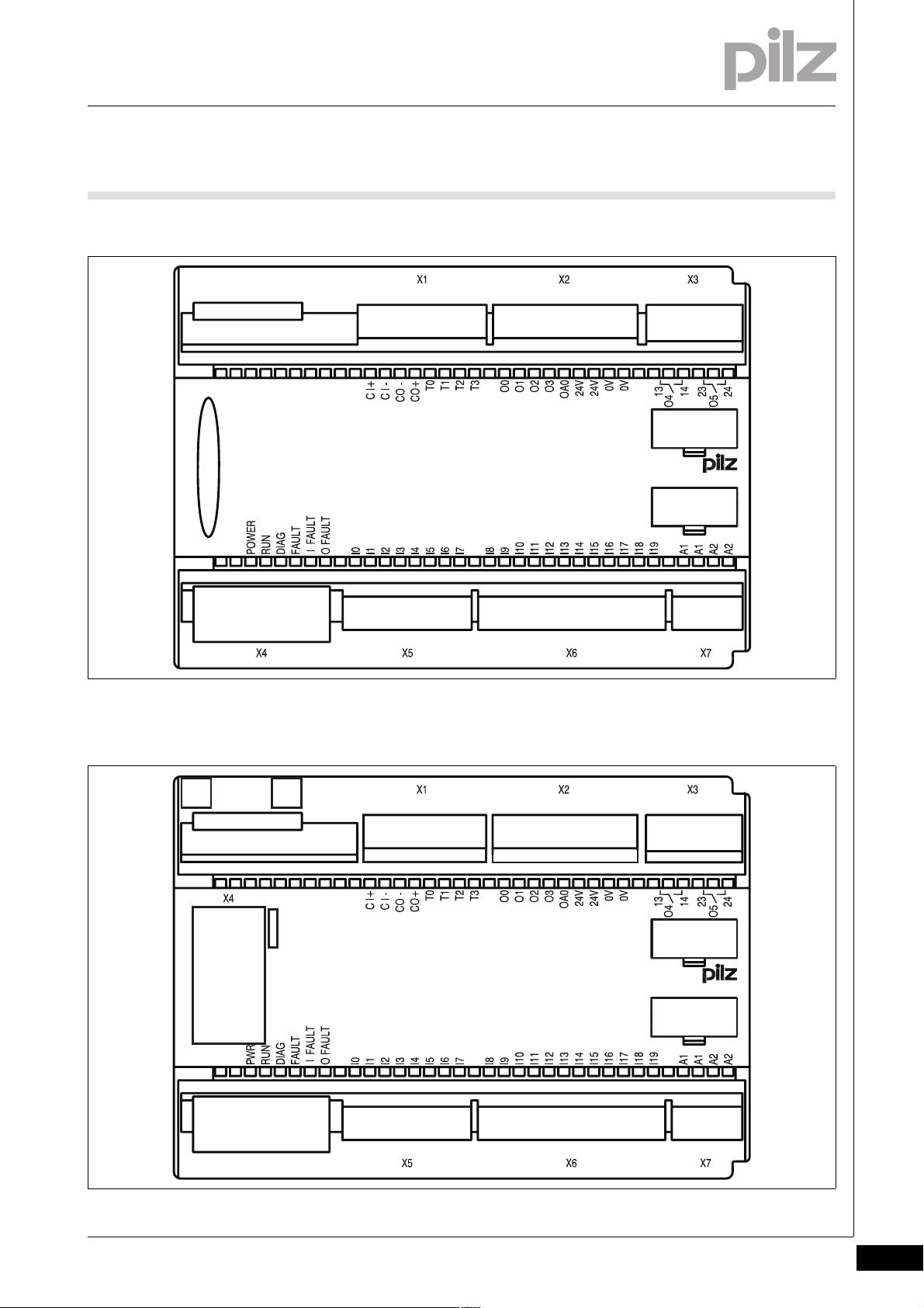
2.2Front view2200Front view2-
2.2.1 PNOZ m0p
PNOZ m0p2-Z-PNOZmulti-Basis-RS232-front-x.EPS
CHIP-Card
2.2.2 PNOZ m0p ETH
PNOZ m0p ETH2-Z-PNOZmulti-Basis-ETH-front-x.EPS
CHIP-Card
LNK
TRF
LNK
TRF
MAC ADD_00-02-47-MAC-VAR
Pilz GmbH & Co. KG, Felix-Wankel-Straße 2, 73760 Ostfildern, Germany
Telephone: +49 711 3409-0, Telefax: +49 711 3409-133, E-Mail: pilz.gmbh@pilz.de
2-3
Page 12

2 Overview
2.2 Front view
2.2.3 Key
Key2-Legende_Klemmenbelegung_multi_Basis_ETH+RS232_BA
Key:
` CHIP card:
– Interface chip card
` X1:
– Cascading inputs and outputs CI and CO,
– Test pulse outputs T0 … T3
` X2:
– Semiconductor outputs O0 ... O3,
– Auxiliary output OA0,
– Supply connections
` X3:
– Relay outputs O4 and O5
` X4:
– RJ 232 interface / Ethernet interface
` X5, X6:
– Inputs I0 ... I19
` X7:
– Power supply
` LEDs:
–PWR
–RUN
– DIAG
–FAULT
–I FAULT
–O FAULT
2-4
Pilz GmbH & Co. KG, Felix-Wankel-Straße 2, 73760 Ostfildern, Germany
Telephone: +49 711 3409-0, Telefax: +49 711 3409-133, E-Mail: pilz.gmbh@pilz.de
Page 13

3 Safety
3.1 Intended use
33000SafetySafety3-3.1Intended use3100Intended use3-Bestimmung/Gertebeschreibung_multi_System
Bestimmung/Gertebeschreibung_multi_Zusatz_Achtung_Standard-Ausgaenge_BA
Bestimmung/Gertebeschreibung_Ausschluss
The modular safety system PNOZmulti is used for the safety-related interruption of safety circuits and is designed for use on:
` E-STOP equipment
` Safety circuits in accordance with VDE 0113 Part 1 and EN 60204-1
CAUTION!
Inputs and outputs for standard functions must not be used for
safety-related applications.
Intended use includes making the electrical installation EMC-compliant.
The product is designed for use in an industrial environment. It is not
suitable for use in a domestic environment, as this can lead to interference.
3.1.1 System requirements
System requirements3-Systemvoraussetzungen
The following is deemed improper use in particular:
` Any component, technical or electrical modification to the product
` Use of the product outside the areas described in this manual
` Use of the product outside the technical details (see chapter entitled
“Technical Details”)
` PNOZmulti Configurator from Version:
– 4.0.0 (PNOZ m0p)
– 7.1.0 (PNOZ m0p ETH)
Please contact Pilz if you have an older version.
Pilz GmbH & Co. KG, Felix-Wankel-Straße 2, 73760 Ostfildern, Germany
Telephone: +49 711 3409-0, Telefax: +49 711 3409-133, E-Mail: pilz.gmbh@pilz.de
3-1
Page 14

3 Safety
3.2 Safety regulations
3.2Safety regulations3200Safety regulat ions3-
3.2.1 Use of qualified personnel
Use of qualified personnel3-Sich Qualif. Personal
The products may only be assembled, installed, programmed, commissioned, operated, maintained and decommissioned by competent persons.
A competent person is someone who, because of their training, experience and current professional activity, has the specialist knowledge required to test, assess and operate the work equipment, devices,
systems, plant and machinery in accordance with the general standards
and guidelines for safety technology.
It is the company's responsibility only to employ personnel who:
` Are familiar with the basic regulations concerning health and safety /
accident prevention
` Have read and understood the safety guidelines given in this descrip-
tion
` Have a good knowledge of the generic and specialist standards ap-
plicable to the specific application.
3.2.2 Warranty and liability
Warranty and liability3-Sich Gewhrleistung
3.2.3 Disposal
Disposal3-Si ch Entsorgung
All claims to warranty and liability will be rendered invalid if:
` The product was used contrary to the purpose for which it is intended
` Damage can be attributed to not having followed the guidelines in the
manual
` Operating personnel are not suitably qualified
` Any type of modification has been made (e.g. exchanging compo-
nents on the PCB boards, soldering work etc.).
` In safety-related applications, please comply with the mission time t
M
in the safety-related characteristic data.
` When decommissioning, please comply with local regulations regard-
ing the disposal of electronic devices (e.g. Electrical and Electronic
Equipment Act).
3-2
Pilz GmbH & Co. KG, Felix-Wankel-Straße 2, 73760 Ostfildern, Germany
Telephone: +49 711 3409-0, Telefax: +49 711 3409-133, E-Mail: pilz.gmbh@pilz.de
Page 15

3 Safety
3.2 Safety regulations
3.2.4 For your safety
For your safety3-Zu Ihrer Sicherheit_multi_Basis
The unit meets all necessary conditions for safe operation. However,
you should always ensure that the following safety requirements are
met:
` This operating manual only describes the basic functions of the unit.
Information on the expanded functions such as cascading can be
found in the online help for the PNOZmulti Configurator and in the
PNOZmulti technical catalogue. Only use these functions after you
have read and understood the documentation. All necessary documentation can be found on the PNOZmulti Configurator CD.
` Adequate protection must be provided for all inductive consumers.
` Do not open the housing or make any unauthorised modifications.
` Please make sure you shut down the supply voltage when performing
maintenance work (e.g. exchanging contactors).
Pilz GmbH & Co. KG, Felix-Wankel-Straße 2, 73760 Ostfildern, Germany
Telephone: +49 711 3409-0, Telefax: +49 711 3409-133, E-Mail: pilz.gmbh@pilz.de
3-3
Page 16

3 Safety
3-4
Pilz GmbH & Co. KG, Felix-Wankel-Straße 2, 73760 Ostfildern, Germany
Telephone: +49 711 3409-0, Telefax: +49 711 3409-133, E-Mail: pilz.gmbh@pilz.de
Page 17

4 Function description
4.1 Unit properties
44000Function descriptionFunction description4-4.1Unit properties4100Unit properties4-
4.1.1 Integrated protection mechanisms
Integrated protection mechanisms4-Sicherheitseigenschaften_multi_allgemein
The relay conforms to the following safety criteria:
` The circuit is redundant with built-in self-monitoring.
` The safety function remains effective in the case of a component fail-
Sicherheitseigenschaften_Relais
Sicherheitseigenschaften_Halbleiter
4.1.2 Function description
Function description4-
ure.
` The relay contacts meet the requirements for safe separation through
increased insulation compared with all other circuits in the safety system.
` The safety outputs are tested periodically using a disconnection test.
4.1.2.1 Operation
Operation4-Funktionen_multi_Basis
The function of the safety system's inputs and outputs depends on the
safety circuit created using the PNOZmulti Configurator. A chip card is
used to download the safety circuit to the base unit. The base unit has
2 microcontrollers that monitor each other. They evaluate the input circuits on the base unit and expansion modules and switch the outputs on
the base unit and expansion modules accordingly.
The LEDs on the base unit and expansion modules indicate the status
of the PNOZmulti safety system.
The online help on the PNOZmulti Configurator contains descriptions of
the operating modes and all the functions of the PNOZmulti safety system, plus connection examples.
Pilz GmbH & Co. KG, Felix-Wankel-Straße 2, 73760 Ostfildern, Germany
Telephone: +49 711 3409-0, Telefax: +49 711 3409-133, E-Mail: pilz.gmbh@pilz.de
4-1
Page 18

4 Function description
4.1 Unit properties
4.1.2.2 Block diagram
Block diagram4-Blockschaltbild_Basis_RS232+ETH
Interface
chip card
module
fieldbus,
Interface
extension
A1 A2
=
Power
I0 I19I1 I2 I3 I8I5
=
I4 I9 I12 I13 I14 I15 I16 I17I7 I18I6
Input
I10
I11
13 23
O4 O5
module
Interface
expansion
RS 232
Ethernet/
4.1.2.3 Diagnostics
Diagnostics4-Funktionen_multi_Basis_Diagnose_ETH und RS232
4.1.2.4 Cascading
Cascading4-Funktionen_multi_Basis_Kaskadierung
Cascading
CI+ CI- CO+
Test pulse
CO-
output
O1
O3
O0
O2
OA0
T3T0
T2T1
24 V 0 V
24 V 0 V
14 24
The status and error messages displayed by the LEDs are saved in an
error stack. This error stack can be read from the PNOZmulti Configurator via the interfaces (RS 232 or Ethernet). More comprehensive diagnostics are possible via the interfaces or one of the fieldbus modules,
e.g. the PROFIBUS module.
The cascading inputs and outputs enable several PNOZmulti and
PNOZelog units to be connected in series or as a tree structure.
4-2
INFORMATION
Detailed information on these functions and connection examples can be found in the online help for the PNOZmulti Configurator and in the PNOZmulti technical catalogue.
Pilz GmbH & Co. KG, Felix-Wankel-Straße 2, 73760 Ostfildern, Germany
Telephone: +49 711 3409-0, Telefax: +49 711 3409-133, E-Mail: pilz.gmbh@pilz.de
Page 19

4 Function description
4.1 Unit properties
4.1.2.5 Safety mat, muting
Safety mat, muting4-Funktionen_multi_Basis_Schaltmatte_Muting
INFORMATION
Detailed information on these functions and connection examples can be found in the online help for the PNOZmulti Configurator and in the supplement to the "PNOZmulti - special
applications" technical catalogue.
4.1.3 Interfaces
Interfaces 4-Funktionen_Schnittstelle_multi_ETH und RS232
The product PNOZ m0pETH has two Ethernet interfaces, the product
PNOZ m0p has one serial interface to
` Download the project
` Read the diagnostic data
` Set virtual inputs for standard functions
` Read virtual outputs for standard functions.
Information on diagnostics via the interfaces can be found in the Special
Applications Technical Catalogue.
The connection to Ethernet is made via the two 8-pin RJ45 sockets.
The Ethernet interface is configured in the PNOZmulti Configurator and
is described in the online help for the PNOZmulti Configurator.
Pilz GmbH & Co. KG, Felix-Wankel-Straße 2, 73760 Ostfildern, Germany
Telephone: +49 711 3409-0, Telefax: +49 711 3409-133, E-Mail: pilz.gmbh@pilz.de
4-3
Page 20

4 Function description
4-4
Pilz GmbH & Co. KG, Felix-Wankel-Straße 2, 73760 Ostfildern, Germany
Telephone: +49 711 3409-0, Telefax: +49 711 3409-133, E-Mail: pilz.gmbh@pilz.de
Page 21

5 Installation
5.1 General installation guidelines
55000InstallationInstallation5-5.1General installation guidelines5100General installation guidelines5-Montage_multi_allgemein
Montage_multi_Bild_BA
` The safety system should be installed in a control cabinet with a pro-
tection type of at least IP54. Fit the safety system to a horizontal DIN
rail. The venting slots must face upward and downward. Other mounting positions could destroy the safety system.
` Use the notches on the back of the unit to attach it to a DIN rail. Con-
nect the safety system to the DIN rail in an upright position so that the
earthing springs on the safety system are pressed on to the DIN rail.
` The ambient temperature of the PNOZmulti units in the control cabi-
net must not exceed the figure stated in the technical details, otherwise air conditioning will be required.
` To comply with EMC requirements, the DIN rail must have a low im-
pedance connection to the control cabinet housing.
Montage_EMV ESD
CAUTION!
Damage due to electrostatic discharge!
Electrostatic discharge can damage components. Ensure
against discharge before touching the product, e.g. by touching
an earthed, conductive surface or by wearing an earthed armband.
Pilz GmbH & Co. KG, Felix-Wankel-Straße 2, 73760 Ostfildern, Germany
Telephone: +49 711 3409-0, Telefax: +49 711 3409-133, E-Mail: pilz.gmbh@pilz.de
5-1
Page 22

5 Installation
5.1 General installation guidelines
5.1.1 Dimensions
Dimensions5-Abmessungen
121 (4.76")
94 (3.70")
135 (5.31")
5-2
Pilz GmbH & Co. KG, Felix-Wankel-Straße 2, 73760 Ostfildern, Germany
Telephone: +49 711 3409-0, Telefax: +49 711 3409-133, E-Mail: pilz.gmbh@pilz.de
Page 23

5 Installation
5.2 Connecting the base unit and expansion modules
5.2Connecting the base unit and expansion modules5200Connecting the base unit and expansion modules5-Montage_multi_Basis_verbind_mit_Modul_links-PNOZ m0p_BA
Jumpers are used to connect the modules.
There are 2 pin connectors on the rear of the base unit.
A max. of 4 expansion modules plus one fieldbus module may be connected to one base unit.
` Connect the base unit, the expansion modules and the fieldbus mod-
ule using the jumpers supplied.
Fieldbus module
Expansion module 1 ... 4
Power supply
Base unit
Jumper
Pilz GmbH & Co. KG, Felix-Wankel-Straße 2, 73760 Ostfildern, Germany
Telephone: +49 711 3409-0, Telefax: +49 711 3409-133, E-Mail: pilz.gmbh@pilz.de
5-3
Page 24

5 Installation
5-4
Pilz GmbH & Co. KG, Felix-Wankel-Straße 2, 73760 Ostfildern, Germany
Telephone: +49 711 3409-0, Telefax: +49 711 3409-133, E-Mail: pilz.gmbh@pilz.de
Page 25

6 Commissioning
6.1 General wiring guidelines
66000CommissioningCommissioning6-6.1General w iring guidelines6100General wiring guidelines6-Verdrahtung_multi_Basis
The wiring is defined in the circuit diagram in the Configurator. There you
can select the inputs that are to perform a particular safety function and
the outputs that will switch this safety function.
Please note:
CAUTION!
DThe plug-in connection terminals on the relay outputs that
carry mains voltage should only be connected and disconnected
when the voltage is switched off.
` Information given in the “Technical details” must be followed.
` Outputs:
– O0 to O5 are safety outputs
– O4 and O5 are relay outputs
– O0 to O3 are semiconductor outputs
– OA0 is an auxiliary output.
` To prevent contact welding, a fuse should be connected before the
output contacts (see technical details).
` Use copper wire that can withstand 75 °C.
` Sufficient fuse protection must be provided on all output contacts
with inductive loads.
` Power for the safety system and input circuits must always be provid-
ed from a single power supply. The power supply must meet the regulations for extra low voltages with safe separation.
` Two connection terminals are available for each of the supply con-
nections 24 V and 0 V (semiconductor outputs), plus A1 and A2 (power supply). This means that the supply voltage can be looped through
several connections. The current at each terminal may not exceed 3
A.
` Test pulse outputs must exclusively be used to test the inputs. They
must not be used to drive loads.
Do not route the test pulse lines together with actuator cables within
Verdrahtung_multi_Basis_Schaltmatte
an unprotected multicore cable.
` Test pulse outputs are also used to supply safety mats that trigger a
short circuit.
Test pulses that are used for the safety mat may not be reused for
other purposes.
Pilz GmbH & Co. KG, Felix-Wankel-Straße 2, 73760 Ostfildern, Germany
Telephone: +49 711 3409-0, Telefax: +49 711 3409-133, E-Mail: pilz.gmbh@pilz.de
6-1
Page 26

6 Commissioning
6.2 Ethernet interfaces (only PNOZ m0p ETH)
6.2Ethernet interfaces (only PNOZ m0p ETH)6200Ethernet interfaces (only PNOZ m0p ETH)6-
6.2.1 RJ45 interfaces ("Ethernet")
RJ45 interfaces ("Ethernet")6-ETH_RJ45-Schnittstellen ("Ethernet")_Switch
Two free switch ports are provided as Ethernet interfaces via an internal
autosensing switch. The autosensing switch automatically detects
whether data transfer is occurring at 10 Mbit/s or 100 Mbit/s.
The switch's automatic crossover function means there is no need to
distinguish on the connection cable between patch cable (uncrossed
data line connection) and crossover cable (crossover data line connection). The switch automatically creates the correct data line connection
internally. It is therefore possible to use patch cable as the connection
cable for both end devices and cascading.
Both Ethernet interfaces use RJ45 technology.
6.2.2 Requirements of the connection cable and connector
Requirements of the connection cable and connector6-ETH_Anforderungen an das Verbindungskabel und den Stecker
The following minimum requirements must be met:
` Ethernet standards (min. Category 5) 10BaseT or 100BaseTX
` Double-shielded twisted pair cable for industrial Ethernet use
` Shielded RJ45 connectors (industrial connectors)
6.2.3 Interface configuration
Interface configuration6-ETH_Schnittstellenbelegung_Switch-8-polig
RJ45 socket
8-pin
8 1
PIN Standard Crossover
1 TD+ (Transmit+) RD+ (Receive+)
2 TD- (Transmit-) RD- (Receive-)
3 RD+ (Receive+) TD+ (Transmit+)
4n.c. n.c.
5n.c. n.c.
6 RD- (Receive-) TD- (Transmit-)
7n.c. n.c.
8n.c. n.c.
6-2
Pilz GmbH & Co. KG, Felix-Wankel-Straße 2, 73760 Ostfildern, Germany
Telephone: +49 711 3409-0, Telefax: +49 711 3409-133, E-Mail: pilz.gmbh@pilz.de
Page 27

6 Commissioning
6.2 Ethernet interfaces (only PNOZ m0p ETH)
6.2.4 RJ45 connection cable
RJ45 connection cable6-ETH_RJ45 Ve rbindungskabel-8-pol ig
RJ45 connector
8-pin
10BaseT cable or 100BaseTX cable
max. 100 m
8
1
ETH_Wichtig_bedingte_Belastbarkeit_Datenkabel
6.2.5 Process data exchange
Process data exchange6-ETH_Prozessdatenaustausch_Switch
The RJ45 interfaces on the internal autosensing switch enable process
data to be exchanged with other Ethernet subscribers within a network.
The product PNOZ m0pETH can also be connected to Ethernet via a
hub (hub or switch).
ETH_Prozessdatenaustausch_Switch_Grafik_multi
NOTICE
With the plug-in connection please note that the data cable and
connector have a limited mechanical load capacity. Appropriate
design measures should be used to ensure that the plug-in connection is insensitive to increased mechanical stress (e.g.
through shock, vibration). Such measures include fixed routing
with strain relief, for example.
Pilz GmbH & Co. KG, Felix-Wankel-Straße 2, 73760 Ostfildern, Germany
Telephone: +49 711 3409-0, Telefax: +49 711 3409-133, E-Mail: pilz.gmbh@pilz.de
6-3
Page 28

6 Commissioning
6.2 Ethernet interfaces (only PNOZ m0p ETH)
Ethernet
Hub/Switch Hub/Switch
Ethernet subscriber
PNOZmulti base unit
with Ethernet interface
Ethernet subscriber
PC with PNOZmulti
Configurator
PNOZmulti base unit
with Ethernet interface
Fig. 6-1: PNOZmulti as Ethernet subscriber - possible topologies
6-4
Pilz GmbH & Co. KG, Felix-Wankel-Straße 2, 73760 Ostfildern, Germany
Telephone: +49 711 3409-0, Telefax: +49 711 3409-133, E-Mail: pilz.gmbh@pilz.de
Page 29

6 Commissioning
6.3 Preparing for operation
6.3Preparing for operation6300Preparing for operation6-
6.3.1 Function test during commissioning
Function test during commissioning6-Verdrahtung_multi_Basis_Betr_Funktionstest_BA
CAUTION!
It is essential to check that the safety devices operate correctly
` after the chip card has been exchanged
` after a project has been downloaded
` when the project has been deleted from the base unit's mem-
ory ("Reset Project" menu)
6.3.2 Commissioning the PNOZmulti safety system for the first time
Commissioning the PNOZmulti safety system for the first time6-Verdrahtung_multi_Basis_Betr_erstes_Mal_BA
Procedure:
` Wire the inputs and outputs on the base unit and expansion modules
in accordance with the circuit diagram.
` Cascading output as auxiliary output: Connect the load to CO+ and
A2, see connection example.
` Connect the supply voltage:
– Supply voltage for the units (connector X7):
– Terminal A1: + 24 VDC
–Terminal A2: 0 V
– Supply voltage for the semiconductor outputs (connector X2):
– Terminal 24 V: + 24 VDC
– 0V terminal: 0 V
Note: Supply voltage must always be applied to X2 and X7, even if you
are not using the semiconductor outputs.
6.3.2.1 Load project from chip card
Load project from chip card6-Verdrahtung_multi_Basis_Betr_erstes_Mal_von_Chipkarte_BA_alt
Procedure:
` Insert the chip card containing the current project into the card slot on
` Switch on the supply voltage.
NOTICE
Chip contacting is only guaranteed if the contact surface is
clean and undamaged. The chip's contact surface should therefore be protected from contamination, contact and mechanical
impact such as scratches.
the base unit.
Pilz GmbH & Co. KG, Felix-Wankel-Straße 2, 73760 Ostfildern, Germany
Telephone: +49 711 3409-0, Telefax: +49 711 3409-133, E-Mail: pilz.gmbh@pilz.de
6-5
Page 30

6 Commissioning
6.3 Preparing for operation
6.3.2.2 Load project via integrated interface
Load project via integrated interface6-Verdrahtung_multi_Basis_Betr_erstes_Mal_Schnittstelle_BA
Procedure:
` Insert a chip card into the chip card slot on the base unit.
` Connect the computer containing the PNOZmulti Configurator to the
base unit via the interface.
` Switch on the supply voltage.
ETH_Info_PC_mit_Ethernet-Karte
` Download the project (see PNOZmulti Configurator's online help).
INFORMATION
You will need a PC with an Ethernet card in order to establish an
Ethernet connection.
6.3.3 Download modified project to the PNOZmulti safety system
Download modified project to the PNOZmulti safety system6-
6.3.3.1 Load modified project from chip card
Load modified project from chip card6-Verdrahtung_multi_Basis_Betr_geaend_Projekt_von_Chipkarte_BA
To download data via chip card, the existing configuration data must
first be deleted (general reset of device).
Procedure:
` Switch off the supply voltage.
` Disconnect all the output terminals.
` Jumper OA0-I19 on the base unit.
` Switch on the supply voltage.
When the "DIAG" LED on the base unit flashes, the memory has been
cleared. The project data can now be downloaded:
` Switch off the supply voltage.
` Remove the old chip card from the chip card slot on the base unit.
` Remove the link from OA0-I19 on the base unit.
` Insert the chip card containing the current project into the card slot.
` Switch on the supply voltage.
6-6
6.3.3.2 Load modified project via integrated interface
Load modified project via integrated interface6-Verdrahtung_multi_Basis_Betr_geaend_Projekt_Schnittstelle_BA
Proceed as described for the initial commissioning
Pilz GmbH & Co. KG, Felix-Wankel-Straße 2, 73760 Ostfildern, Germany
Telephone: +49 711 3409-0, Telefax: +49 711 3409-133, E-Mail: pilz.gmbh@pilz.de
Page 31

6 Commissioning
6.3 Preparing for operation
6.3.4 Connection
Connection6-Betriebsbereitschaft he rstellen multi Basige rät
` Supply voltage
Supply voltage AC DC
For the safety system
(connector X7)
A1
+ 24 V DC
For the semiconductor outputs
(connector X2)
Must always be present, even if the
semiconductor outputs are not used
` Connection examples for the input circuit
Input circuit Single-channel Dual-channel
E-STOP
without detection of shorts across
S1
I0
L+
contacts
E-STOP
with detection of shorts across con-
S1
I0
tacts
T0
A2
24 V
0 V
I0
I1
T1
T0
0 V
+ 24 V DC
0 V
S1
I0
I1
L+
L+
S1
` Connection examples for reset circuit
Reset circuit Input circuit without detection of
shorts across contacts
S3
I5
Pilz GmbH & Co. KG, Felix-Wankel-Straße 2, 73760 Ostfildern, Germany
Telephone: +49 711 3409-0, Telefax: +49 711 3409-133, E-Mail: pilz.gmbh@pilz.de
Input circuit with detection of shorts
across contacts
S3
I5
L+
T0
6-7
Page 32

6 Commissioning
6.3 Preparing for operation
` Connection examples for semiconductor outputs
Redundant output
Single output
` Connection examples for relay outputs
Redundant output
O0 (O2)
O1 (O3)
O0 (O2)
O1 ( O3)
13
O4
14
23
O5
24
K1
K2
K1
K2
K3
K4
K1
K2
L-
L-
L-
L-
L1
N
Single output
O4
O5
` Connection examples for feedback loop
Feedback loop Redundant output
Contacts from external contactors
O0 (O2, O4)
O1 (O3, O5)
13
14
23
24
K2
I0
K2
K1
K1
L1
N
L-
L-
L+
6-8
Pilz GmbH & Co. KG, Felix-Wankel-Straße 2, 73760 Ostfildern, Germany
Telephone: +49 711 3409-0, Telefax: +49 711 3409-133, E-Mail: pilz.gmbh@pilz.de
Page 33

6 Commissioning
6.4 Connection example
6.4Connection example6400Connection example6-Anschlussbeispiel_Basisgeräte_BA
Dual-channel E-STOP and safety gate wiring, monitored reset (I17),
feedback loop (I14), cascading output as auxiliary output (CO+/A2)
L+
L-
CI+
CI-
CO-
CO+T0T1T2T3O0O1O2O3
OA0
24V
24V0V0V13142324
K1
K2
I0I1I2I3I4I5I6I7I8I9I10
S1
I11
I12
I13
I14
I15
I16
I17
I18
I19A1A1A2A2
K2
S2
S3
K1
Pilz GmbH & Co. KG, Felix-Wankel-Straße 2, 73760 Ostfildern, Germany
Telephone: +49 711 3409-0, Telefax: +49 711 3409-133, E-Mail: pilz.gmbh@pilz.de
6-9
Page 34

6 Commissioning
6-10
Pilz GmbH & Co. KG, Felix-Wankel-Straße 2, 73760 Ostfildern, Germany
Telephone: +49 711 3409-0, Telefax: +49 711 3409-133, E-Mail: pilz.gmbh@pilz.de
Page 35

7 Operation
7.1 Messages
77000OperationOperation7-7.1Messages71 00Messages7-Betr ieb_Meldungen_Basi s_BA
The PNOZmulti safety system is ready for operation when the "POWER"
and "RUN" LEDs on the base unit are lit continuously.
7.1.1 Display elements for device diagnostics
Display elements for device diagnostics 7-Anzeige Legende 3x
Key:
LED on
LED flashes
LED off
Betrieb_Anzeige_multi_Bas is_ETH_BA
Basic Exp. Errors
Input Ix
RUN
DIAG
FAULT
IFAULT
OFAULTCICO
FAULT
IN/OUT
The existing user program has been deleted.
External error on the base unit, leading to a safe condition, e.g.
terminator not connected.
External error, leading to a safe condition, e.g. short across the
contacts or error on safety mat input.
External error on the outputs of the base unit, e.g. short across
the contacts, leading to a safe condition.
External error, leading to a safe condition, e.g. short across the
contacts.
External error on the output
Internal error on the base unit
Internal error on the base unit
Internal error on the base unit
Internal error on the expansion module
Base unit in a STOP condition
External error on the inputs of the base unit, which does not
lead to a safe condition, e.g. partially operated.
External error on the outputs of the base unit, which does not
lead to a safe condition, e.g. feedback input defective.
External error on the inputs, which does not lead to a safe condition, e.g. partially operated; feedback input defective.
Pilz GmbH & Co. KG, Felix-Wankel-Straße 2, 73760 Ostfildern, Germany
Telephone: +49 711 3409-0, Telefax: +49 711 3409-133, E-Mail: pilz.gmbh@pilz.de
7-1
Page 36

7 Operation
7.1 Messages
The fieldbus module has not been recognised.
Or
The base unit was identified via the PNOZmulti Configurator.
Error on cascading input; unit remains in a RUN condition.
Error on cascading output; unit remains in a RUN condition.
7.1.2 Display elements for the Ethernet connection (only PNOZ m0p ETH)
Display elements for the Ethernet connection (only PNOZ m0p ETH)7-ETH_Anzeigeelemente_fuer_Ethernet_LNK_TRF
The operating statuses and fault conditions of the Ethernet connection
are shown via the LEDs LNK (link) and TRF (traffic) at the Ethernet interfaces.
LED Signal Meaning
LNK
(green)
No network connection
Network connection present
TRF (yellow)
No data traffic
Data traffic present
7-2
Pilz GmbH & Co. KG, Felix-Wankel-Straße 2, 73760 Ostfildern, Germany
Telephone: +49 711 3409-0, Telefax: +49 711 3409-133, E-Mail: pilz.gmbh@pilz.de
Page 37

7 Operation
7.2 Reset Ethernet connection settings
7.2Reset Ethernet connection settings7200Reset Ethernet connection settings7-ETH_Verbindungseinstellungen_zuruecksetzen_multi
The Ethernet connection settings of the base unit can be configured in
the PNOZmulti Configurator.
You can reset the base unit's Ethernet connection settings to the default
settings.
Proceed as follows:
` Switch off the supply voltage
` Remove the chip card
` Restart the base unit without the chip card inserted.
The Ethernet connection settings are now reset to the default settings.
Pilz GmbH & Co. KG, Felix-Wankel-Straße 2, 73760 Ostfildern, Germany
Telephone: +49 711 3409-0, Telefax: +49 711 3409-133, E-Mail: pilz.gmbh@pilz.de
7-3
Page 38

7 Operation
7-4
Pilz GmbH & Co. KG, Felix-Wankel-Straße 2, 73760 Ostfildern, Germany
Telephone: +49 711 3409-0, Telefax: +49 711 3409-133, E-Mail: pilz.gmbh@pilz.de
Page 39

8 Technical details
8.1 Technical details
88000Technical detailsTechnical details8-8.1Technical details8100Technical details8-][Technische Daten_multi_Basis
Technical details
Electrical data
Supply voltage UB DC 24 V
Voltage tolerance -15 %/+20 %
Power consumption at U
without load 8.0 W No. 773110
per expansion module 2.50 W
Residual ripple DC 5 %
Status display LED
Times
Switch-on delay 5.00 s
Simultaneity channel 1/2/3 3 s
Two-hand circuit 0.5 s
Supply interruption before de-energisation 20 ms
Inputs
Number 20
Max. number of live inputs in the area of max. permitted
ambient temperature (see "Environmental data")
Voltage and current at input, reset and feedback circuit 24.0 V, 8.0 mA
Galvanic isolation no
Signal level at "0" -3 - +5 V DC
Signal level at "1" 15 - 30 V DC
Min. pulse duration 18 ms
Pulse suppression 0.6 ms
Test pulse outputs
Number of test pulse outputs 4
Voltage and current, 24 V 0.5 A
Off time during self test 5 ms
Galvanic isolation no
Short circuit-proof yes
Semiconductor outputs
Number 4
Switching capability
voltage 24 V
current 2 A
power 48 W
Max. capacitive load 1 µF
External supply voltage 24.0 V
Voltage tolerance -15 %/+20 %
Max. duration of off time during self test 300 µs
Galvanic isolation yes
Short circuit-proof yes
Switch-off delay 30 ms
Residual current at "0" 0.5 mA
Signal level at "1" UB - 0.5 V DC bei 2 A
Relay outputs
Number 2
DC
B
9.0 W No. 773113
U_B > 26.4 V : 15, U_B <= 26.4 V : 20
Pilz GmbH & Co. KG, Felix-Wankel-Straße 2, 73760 Ostfildern, Germany
Telephone: +49 711 3409-0, Telefax: +49 711 3409-133, E-Mail: pilz.gmbh@pilz.de
8-1
Page 40

8 Technical details
8.1 Technical details
Relay outputs
Utilisation category in accordance with EN 60947-4-1
Safety contacts: AC1 at 240 V 6.0 A, 1440 VA
Safety contacts: DC1 at 24 V 6.0 A, 144 W
Utilisation category in accordance with EN 60947-5-1
Safety contacts: AC15 at 230 V 3.0 A, 690 W
Safety contacts: DC13 at 24 V (6 cycles/min) 3.0 A, 72 W
Airgap creepage between
relay contacts 3 mm
relay contacts and other safe circuits 5.5 mm
External contact fuse protection (I
EN 60947-5-1
Blow-out fuse, quick 6 A
Blow-out fuse, slow 6 A
Circuit breaker 24 VAC/DC, characteristic B/C 6 A
Switch-off delay 50 ms
Auxiliary outputs
Number 1
Switching capability
voltage 24 V
current 0.5 A
power 12.0 W
Galvanic isolation yes
Short circuit-proof yes
Residual current at "0" 0.5 mA
Signal level at "1" UB - 0.5 V DC bei 0.5 A
Cascading output as auxiliary output
Number 1
Switching capability
voltage 24 V
current 0.2 A
power 4.8 W
Galvanic isolation no
Short circuit-proof yes
Residual current at "0" 0.5 mA
Environmental data
EMC EN 60947-5-1
Vibration to EN 60068-2-6
Frequency 10 - 55 Hz
Amplitude 0.35 mm
Climatic suitability EN 60068-2-78
Airgap creepage in accordance with EN 60664-1
Ambient temperature 0 - 60 °C
Storage temperature -25 - 70 °C
Mechanical data
Protection type
Mounting (e.g. cabinet) IP54
Housing IP20
Terminals IP20
DIN rail
Top hat rail 35 x 7.5 EN 50022
Recess width 27 mm
= 1 kA) to
K
8-2
Pilz GmbH & Co. KG, Felix-Wankel-Straße 2, 73760 Ostfildern, Germany
Telephone: +49 711 3409-0, Telefax: +49 711 3409-133, E-Mail: pilz.gmbh@pilz.de
Page 41

8 Technical details
8.1 Technical details
Mechanical data
Maximum cable runs
per input 1 km
Sum of individual cable runs at the test pulse output 40 km
Housing material
Housing PPO UL 94 V0
Front ABS UL 94 V0
Cross section of external conductors with screw terminals
Power supply, inputs, auxiliary output, semiconductor out-
puts, test pulse outputs, cascading outputs:
1 core flexible 0.50 - 1.50 mm² , 22 - 14 AWG No. 773113
0.50 - 2.50 mm² , 22 - 14 AWG No. 773110
2 core, same cross section, flexible:
with crimp connectors, without insulating sleeve 0.50 - 0.75 mm² , 22 - 20 AWG
without crimp connectors or with TWIN crimp connectors 0.50 - 0.75 mm² , 22 - 20 AWG
Relay outputs:
1 core flexible 0.5 - 1.5 mm² No. 773110
0.5 - 2.5 mm² No. 773113, 22 - 12 AWG
2 core, same cross section, flexible:
with crimp connectors, without insulating sleeve 0.50 - 1.25 mm², 22 - 16 AWG
without crimp connectors or with TWIN crimp connectors 0.50 - 1.25 mm², 22 - 16 AWG
Torque setting with screw terminals 0.25 Nm
Cross section of external conductors with spring-loaded
terminals: Flexible with/without crimp connectors
Spring-loaded terminals: Terminal points per connection 1
Stripping length 9 mm
Dimensions
Height 94.0 mm
Width 135.0 mm
Depth 121.0 mm
Weight 490 g No. 773110
Technische Daten_Satz No .
0.50 - 1.50 mm² , 26 - 14 AWG
520 g No. 773113
Si-Kennzahlen_alle
Safety characteristic data
Unit Operating mode
Logic
CPU PL e (Cat. 4) Cat. 4 SIL CL 3 4.90E-09 20
Input
SC inputs single-channel PL d (Cat. 2) Cat. 2 SIL CL 2 2.50E-09 20
SC inputs dual-channel PL e (Cat. 4) Cat. 4 SIL CL 3 2.90E-10 20
SC inputs light beam device PL e (Cat. 4) Cat. 4 SIL CL 3 2.50E-10 20
SC inputs dual-channel pres-
sure sensitive mat
cascading inputs PL e (Cat. 4) Cat. 4 SIL CL 3 3.10E-10 20
Output
SC outputs single-channel PL d (Cat. 2) Cat. 3 SIL CL 2 7.00E-09 20
SC outputs dual-channel PL e (Cat. 4) Cat. 4 SIL CL 3 8.60E-10 20
cascading outputs PL e (Cat. 4) Cat. 4 SIL CL 3 4.91E-10 20
Pilz GmbH & Co. KG, Felix-Wankel-Straße 2, 73760 Ostfildern, Germany
Telephone: +49 711 3409-0, Telefax: +49 711 3409-133, E-Mail: pilz.gmbh@pilz.de
No. stands for order number.
EN ISO 13849-1PLEN 954-1
Category
PL d (Cat. 3) Cat. 3 SIL CL 2 1.81E-09 20
EN IEC 62061
SIL CL PFH [1/h] tM [year]
8-3
Page 42

8 Technical details
8.1 Technical details
Output
relay outputs single-channel PL c (Cat. 1) Cat. 2 - 2.90E-08 20
relay outputs dual-channel PL e (Cat. 4) Cat. 4 SIL CL 3 3.00E-10 20
Si-Kennzahlen_Zusatz_Relais_1kan_EN954_Cat2
Requirement on 1-channel relay outputs for Cat. 2 in accordance with
EN 954-1: An additional output switches to a safe condition in the event
Si_Kennzahlen_Erläuterung
Technische Daten_Satz No rmen
of an error or, if that is impossible, signals a hazardous condition.
All the units used within a safety function must be considered when calculating the safety characteristic data.
Si-Kennzahlen_Zusatz_Relais_Lebensdauer_BA
The standards current on 2009-03 apply.
CAUTION!
It is essential to consider the relay's service life graphs. The relay
outputs' safety-related characteristic data is only valid if the values in the service life graphs are met.
The PFH value depends on the switching frequency and the load on the
relay output. If the service life graphs are not accessible, the stated PFH
value can be used irrespective of the switching frequency and the load,
as the PFH value already considers the relay's B10d value as well as the
failure rates of the other components.
8-4
Pilz GmbH & Co. KG, Felix-Wankel-Straße 2, 73760 Ostfildern, Germany
Telephone: +49 711 3409-0, Telefax: +49 711 3409-133, E-Mail: pilz.gmbh@pilz.de
Page 43

8 Technical details
8.2 Service life graph of output relays
8.2Service life graph of output relays8200Service life graph of output relays8-Lebensda uerkurve_Relais_T ext vor Kurve
The service life graphs indicate the number of cycles from which failures
due to wear must be expected. The wear is mainly caused by the elec-
Lebensdauerkurve SIS_212
trical load; the mechanical load is negligible.
Lebensdauerkurve_Relai s_Text nach Kurv e_SIS212_SIR-SLR B sp
10
1
D Nennbetriebstrom (A)
GB Nominal operating current (A)
F Courant coupé (A)
0.1
E Corriente nominal de servicio (A)
I Corrente di esercizio nominale (A)
NL Nominale bedrijfsstroom (A)
10 100 1000 10000
D Schaltspielzahl x 10
GB Cycles x 10
F Nombre de manuvres x 10
AC15: 230 V
DC13: 24 V
3
AC1: 230 V
3
DC1: 24 V
E Número de ciclos x 10
I Numero dei cicli di commutazione x 10
3
NL Aantal schakelingen x 10
3
3
Example
` Inductive load: 0.2 A
` Utilisation category: AC15
` Contact service life: 1 000 000 cycles
Provided the application requires fewer than 1 000 000 cycles, the PFH
value (see technical details) can be used in the calculation.
3
To increase the service life, sufficient spark suppression must be provided on all output contacts. With capacitive loads, any power surges that
occur must be noted. With contactors, use freewheel diodes for spark
suppression.
Lebensdauerkurve_Relais_Text nach Kurve-2_ Empfehlung Halbleiterausgänge
We recommend you use semiconductor outputs to switch 24 VDC
loads.
Pilz GmbH & Co. KG, Felix-Wankel-Straße 2, 73760 Ostfildern, Germany
Telephone: +49 711 3409-0, Telefax: +49 711 3409-133, E-Mail: pilz.gmbh@pilz.de
8-5
Page 44

8 Technical details
8.3 Maximum capacitive load C (mF) with load current I (mA) at the semiconductor outputs
8.3Maximum capacitive load C (μF) with load current I (mA) at the semiconductor outputs8300Maximum capacitive load C (μF) with load current I (mA) at the semiconductor outputs8-Kapazitaet
C (µF)
6
4
2
0
0 10 50 100 200 400 600 800
1000
1400 1600 1800 2000
1200 I (mA)
8-6
Pilz GmbH & Co. KG, Felix-Wankel-Straße 2, 73760 Ostfildern, Germany
Telephone: +49 711 3409-0, Telefax: +49 711 3409-133, E-Mail: pilz.gmbh@pilz.de
Page 45

8 Technical details
8.4 Order reference
8.4Order reference8400Order reference8-Bes telldaten
Order reference
Type Features Order no.
PNOZ m0p Base unit 773 110
PNOZ m0p ETH Base unit 773 113
Pilz GmbH & Co. KG, Felix-Wankel-Straße 2, 73760 Ostfildern, Germany
Telephone: +49 711 3409-0, Telefax: +49 711 3409-133, E-Mail: pilz.gmbh@pilz.de
8-7
Page 46

8 Technical details
8-8
Pilz GmbH & Co. KG, Felix-Wankel-Straße 2, 73760 Ostfildern, Germany
Telephone: +49 711 3409-0, Telefax: +49 711 3409-133, E-Mail: pilz.gmbh@pilz.de
Page 47

© Pilz GmbH & Co. KG, 2010
1002053-EN-03, 2010-10 Printed in Germany
... www
In many countries we are
represented by our subsidiaries
and sales partners.
Please refer to our homepage
for further details or contact our
headquarters.
www.pilz.com
Technical support
+49 711 3409-444
support@pilz.com
are registered and protected trademarks
®
, the spirit of safety
®
, SafetyNET p
®
, SafetyEYE
®
, SafetyBUS p
®
, PVIS
®
, PSS
®
, PSEN
®
, Primo
®
, PNOZ
®
, PMI
®
Pilz GmbH & Co. KG
Felix-Wankel-Straße 2
73760 Ostfildern, Germany
Telephone: +49 711 3409-0
Telefax: +49 711 3409-133
E-Mail: pilz.gmbh@pilz.de
, PMCprotego
®
, PIT
®
, Pilz
®
InduraNET p
of Pilz GmbH & Co. KG in some countries. We would point out that product features may vary from the details stated in this document, depending on the status at the time of publication and the scope
of the equipment. We accept no responsibility for the validity, accuracy and entirety of the text and graphics presented in this information. Please contact our Technical Support if you have any questions.
 Loading...