

Page 1

21007-3FR-03
PNOZ Ex
4
D Betriebsanleitung
4
GB Operating instructions
4
F Manuel d'utilisation
Sicherheitsbestimmungen
• Das Gerät darf nur von Personen
installiert und in Betrieb genommen
werden, die mit dieser Betriebsanleitung
und den geltenden Vorschriften über
Arbeitssicherheit und Unfallverhütung
vertraut sind. Beachten Sie die VDEsowie die örtlichen Vorschriften, insbesondere hinsichtlich Schutzmaßnahmen.
• Beim Transport, der Lagerung und im
Betrieb die Bedingungen nach EN 600682-6 einhalten (s. technische Daten).
• Durch Öffnen des Gehäuses oder
eigenmächtige Umbauten erlischt jegliche
Gewährleistung.
• Montieren Sie das Gerät in einen
Schaltschrank; Staub und Feuchtigkeit
können sonst zu Beeinträchtigungen der
Funktionen führen.
• Sorgen Sie an allen Ausgangskontakten
bei kapazitiven und induktiven Lasten für
eine ausreichende Schutzbeschaltung.
• Hinweis für Überspannungskategorie III:
Wenn am Gerät höhere Spannungen als
Kleinspannung (>50 V AC oder
>120 V DC) anliegen, müssen angeschlossene Bedienelemente und Sensoren eine Bemessungsisolationsspannung
von mind. 250 V aufweisen.
Safety Regulations
• The unit may only be installed and
operated by personnel who are familiar
with both these instructions and the
current regulations for safety at work and
accident prevention. Follow CEN and
local regulations especially as regards
preventative measures.
• Transport, storage and operating
conditions should all conform to EN
60068-2-6.
• Any guarantee is void following opening of
the housing or unauthorised
modifications.
• The unit should be panel mounted,
otherwise dampness or dust could lead to
function impairment.
• Adequate protection must be provided on
all output contacts with capacitive and
inductive loads.
• Note for overvoltage category III:
If voltages higher than low voltage
(>50 VAC or >120 VDC) are present on
the unit, connected control elements and
sensors must have a rated insulation
voltage of at least 250 V.
Conseils préliminaires
• La mise en oeuvre de l’appareil doit être
effectuée par une personne spécialisée
en
installations électriques, en tenant compte
des prescriptions des différentes normes
applicables (NF, EN, VDE..), notamment
au niveau des risques encourus en cas
de
défaillance de l’équipement électrique.
• Respecter les exigences de la norme
EN 60068-2-6 lors du transport, du
stockage et de l’utilisation de l’appareil.
• L’ouverture du boîtier annule automatiquement la clause de garantie.
• Installez le relais dans une armoire
electrique à l’abri de la poussière et de
l’humidité.
• Assurez-vous du pouvoir de coupure des
contacts de sortie en cas de charges
inductives ou capacitives.
• Remarque relative à la catégorie de
surtensions III :
Si l’appareil est alimenté avec des tensions
supérieures à la basse tension (>50 V AC
ou >120 V DC), les éléments de
commande et les capteurs raccordés
doivent supporter une tension d’isolement
assignée d’au moins 250 V.
Bestimmungsgemäße Verwendung
Das Sicherheitsschaltgerät dient dem
sicherheitsgerichteten Unterbrechen eines
Sicherheitsstromkreises. Das Sicherheitsschaltgerät erfüllt Forderungen der
EN 60947-5-1, EN 60204-1 und VDE 01131 und darf eingesetzt werden in Anwendungen mit
• Not-Halt-Tastern
• Schutztüren
• explosionsgefährdeten Bereichen nach
EN 50014 und EN 50020
Das Gerät ist für die Absicherung von
berührungslosen Verdeckungen geeignet,
da ein dynamischer Start möglich ist.
Gerätebeschreibung
Das Sicherheitsschaltgerät PNOZ Ex ist in
einem P-93-Gehäuse untergebracht. Es
stehen verschiedene Varianten für den
Betrieb mit Wechselspannung zur Verfügung.
Merkmale:
• Relaisausgänge (zwangsgeführt):
- drei Sicherheitskontakte (Schließer)
- ein Hilfskontakt im eigensicheren
Bereich (Schließer)
- ein Hilfskontakt für Sicherung im
eigensicheren Bereich (Schließer)
- ein Hilfskontakt im nicht eigensicheren
Bereich (Öffner)
• Anschlussmöglichkeit für Not-HaltTaster, Schutztürgrenztaster und
Starttaster
• Statusanzeige
• Rückführkreis zur Überwachung
externer Schütze
• nur zweikanalige Ansteuerung zulässig
•
Ex-Bereich, Zündschutzart [EEx ia] II C/II B
Authorised Applications
The safety relay provides a safety-related
interruption of a safety circuit. The safety
relay meets the requirements of EN 609475-1, EN 60204-1 and VDE 0113-1 and may
be used in applications with
• E-STOP pushbuttons
• Safety gates
• Potentially explosive areas to EN 50014
and EN 50020.
The unit is suitable for use with non-contact
guards, as a dynamic start is possible.
Description
The Safety Relay PNOZ Ex is enclosed in a
P-93 housing. There are different versions
available for AC operation.
Features:
• Relay outputs, positive-guided:
- three safety contacts (N/O)
- one auxiliary contact in the intrinsically
safe area (N/O)
- one auxiliary contact (N/O) for fusing in
the intrinsically safe area
- one auxiliary contact (N/C) in the non-
intrinsuaclly safe area
• Connections for emergency stop button,
safety gate limit switch and reset button.
• Status Indicators
• Feedback control loop for monitoring of
external contactors/relays.
• Two channel operation only
• Ex-area, Ex-protection [EEx ia] II C/II B
- 1 -
Domaine d’utilisation
Le bloc logique de sécurité sert à
interrompre en toute sécurité un circuit de
sécurité. Le bloc logique de sécurité satisfait
aux exigences des normes EN 60947-5-1,
EN 60204-1 et VDE 0113-1 et peut être
utilisé dans des applications avec des
• poussoirs d'arrêt d'urgence
• protecteurs mobiles
• dans les zones explosives conformément
aux normes EN 50014 et EN 50020.
L’appareil est adapté à la surveillance de
barrières immatérielles car une validation
dynamique est possible.
Description de l’appareil
Inséré dans un boîtier P-93, le bloc logique
PNOZ Ex est disponible en différentes
versions pour les tensions d’alimentation
alternatives.
Caractéristiques :
• Contacts de sortie :
- 3 contacts à fermeture de sécurité
- 1 contact à ouverture d’ info en partie
intrinséque
- 1 contact à ouverture fusible interne en
partie intrinséque
- 1 contact à ouverture d’info en partie
normale
• raccordement pour poussoir AU, capteur
et poussoir de validation
• LEDs de visualisation
• boucle de retour pour l’auto-contrôle des
contacteurs externes
Page 2
Das Schaltgerät erfüllt folgende Sicherheitsanforderungen:
• Schaltung ist redundant mit Selbstüberwachung aufgebaut.
• Sicherheitseinrichtung bleibt auch bei
Ausfall eines Bauteils wirksam.
• Bei jedem Ein-Aus-Zyklus der Maschine
wird automatisch überprüft, ob die Relais
der Sicherheitseinrichtung richtig öffnen
und schließen.
• Vor Kurzschluss schützt eine Schmelzsicherung
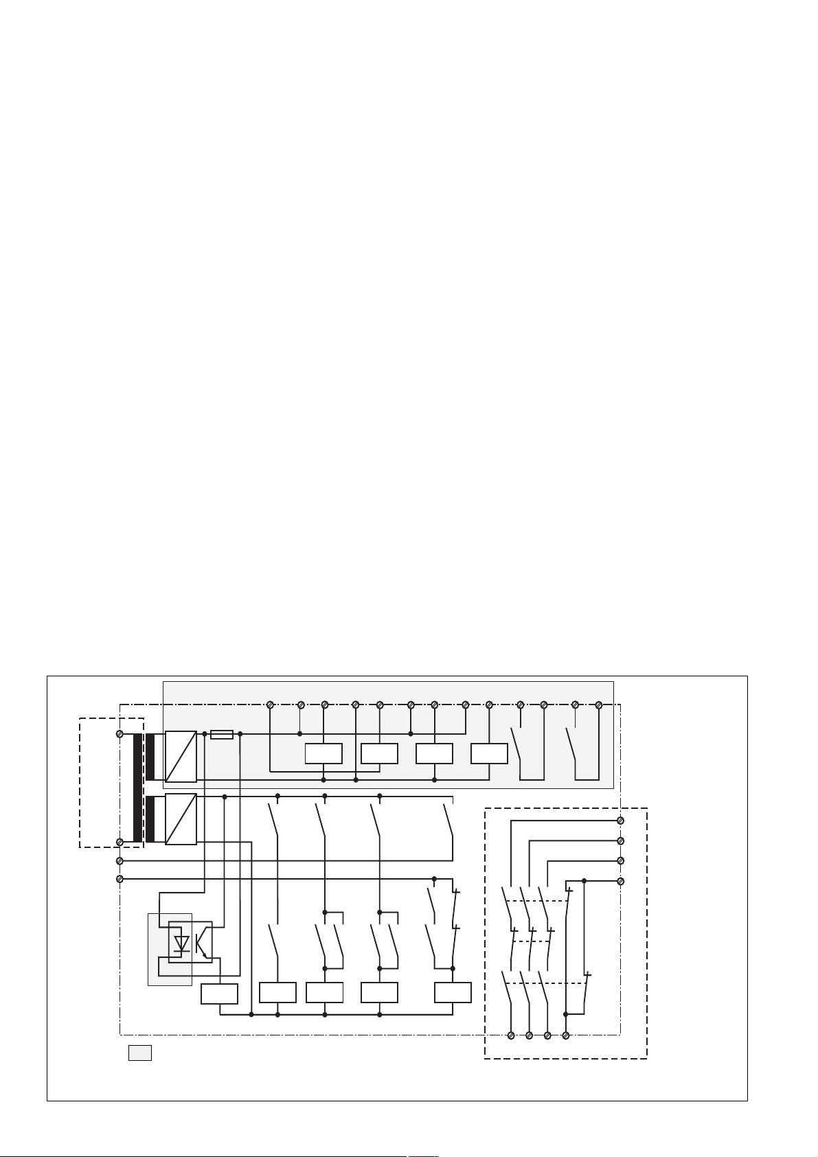
Funktionsbeschreibung
Das Schaltgerät PNOZ Ex dient dem
sicherheitsgerichteten Unterbrechen eines
Sicherheitsstromkreises. Es ist in einen
eigensicheren und einen nicht eigensicheren Bereich unterteilt (s. Fig. 1). Nach
Anlegen der Versorgungsspannung,
Brücken von Y1-Y2 und S33-S34 geht
Relais K3 in Wirkstellung.
• Eingangskreis geschlossen (z. B. NotHalt-Taster nicht betätigt)
Relais K1 und K2 gehen über ihre
Schließer in Wirkstellung und halten sich
selbst. Die Statusanzeigen "Channel 1"
und "Channel 2" leuchten. Durch Öffnen
der Öffnerkontakte von K1 und K2 geht K3
nach Ablauf der Rückfallverzögerung in
Ruhestellung. Die Sicherheitskontakte 1314/23-24/33-34 und der Hilfskontakt 53-54
ist geschlossen, der Hilfskontakt 41-42 ist
geöffnet. Die LED "Ch1/Ch2" leuchtet.
• Eingangskreis wird geöffnet (z. B. NotHalt-Taster betätigt)
K1 und K2 fallen in die Ruhestellung
zurück. Die Sicherheitskontakte 13-14/
23-24/33-34 und der Hilfskontakt 53-53
wird redundant geöffnet, der Hilfskontakt
41-42 geschlossen.
Der Hilfskontakt 63-64 zeigt den Zustand
der Sicherung an:
• Sicherung nicht ausgelöst: 63-64 offen
• Sicherung ausgelöst: 63-64 geschlossen
The relay complies with the following safety
requirements:
• The circuit is redundant with built-in selfmonitoring.
• The safety function remains effective in
the case of a component failure.
• The correct opening and closing of the
safety function relays is tested
automatically in each on-off cycle.
• Short-circuit fusing: A fuse protects
against short-circuits.
Function Description
The relay PNOZ Ex provides a failsafe
interruption of a safety circuit. It consists of
two parts: intrinsically safe and nonintrinsically safe areas (see Fig. 1).
When the operating voltage is supplied, Y1Y2 and S33-S34 are linked, relay K3
energises.
• Input circuit closed (e.g. emergency stop
button not activated):
Relays K1 and K2 energise via their N/O
contacts and latch. The status indicators
'Channel 1' and 'Channel 2' illuminate. By
opening the N/C contacts of K1 and K2,
K3 de-energises following the delay-on
de-energisation. The safety contacts (1314/23-24/33-34) and the auxiliary contact
53-54 are closed, the auxiliary contact
41-42 is open. The LED " Ch 1/Ch 2"
illuminate.
• Input circuit opened (e.g. emergency stop
button activated):
K1 and K2 de-energise. The safety
contacts (13-14/23-24/33-34) and the
auxiliary contact 53-54 are opened
redundantly, the auxiliary contact (41-42)
is closed.
The auxiliary contact 63-64 shows the fuse
status
• fuse intact: 63-64 is open
• fuse not intact: 63-64 is closed.
• commande en 2 canaux uniquement
• Zone EX, protection [EEx ia] II C/II B
Le bloc logique répond aux exigences
suivantes :
• conception redondante avec autosurveillance
• fonction de sécurité garantie même en
cas de défaillance d’un composant
électronique.
• Test cyclique des relais internes à
chaque
mise sous tension de la machine.
• Protection par fusible contre les
courtscircuits
Description du fonctionnement
Le bloc logique PNOZ EX assure de façon
sûre l’ouverture d’un circuit de sécurité. Il
est composé d’une partie intrinséquement
sûre et d’une partie normale (voir fig. 1).
Dès que la tension d’alimentation est
présente et si les bornes Y1-Y2 et S33-S34
sont pontées, le relais K3 colle.
• Circuit d’entrée fermé (par ex. poussoir
AU
non actionné):
Les relais K1 et K2 passe en position
travail et s’auto-maintiennent. Les LEDs
„Channel 1“ et „Channel 2“ s’allument.
L’ouverture des contacts à ouverture de
K1 et K2 fait retomber le relais K3.
Les contacts de sécurité (13-14/23-24/
33-
34) et le contact d’info. 53-54 se ferment,
le contact d’info. 41-42 s’ouvre. Les
LEDs „Ch1/Ch2“ sont allumées.
• Circuit d’entrée ouvert (par ex. poussoir
AU actionné):
K1 et K2 retombent. Les contacts de
sécurité (13-14/23-24/33-34) et le contact
d’info. 53-54 s’ouvrent et le contact
d’info. (41-42) se ferme.
Le contact d’info. 63-64 indique l’état du
fusible interne :
• Fusible non déclenché : 63-64 ouvert
• Fusible déclenché : 63-64 fermé
S11S52 S12 S21 S22 S33 S34 Y36 Y37
*
A1
U
B
A2
~
+
F1
K4
K5 K6 K7
-
~
+
K1
K4 K5 K6
Y1
Y2
K2
K9
Eigensicherer Bereich/Intrinsically Safe Area/Partie intrinséque
Fig. 1: Schematisches Schaltbild/Connection Diagram/Schéma de principe
K1
K8
K3
K2 K3
K2 K3K1
K7
K3
K1
K2
K1
K3
K2
53 54
K8
2414 34 42
63 64
K9
*
13
23
33
41
- 2 -
Page 3
* Isolation zum nicht markierten Bereich und der
Relaiskontakte zueinander: Basisisolierung
(Überspannungskategorie III), sichere
Trennung (Überspannungskategorie II)
Betriebsarten:
• Zweikanaliger Betrieb: Redundanter
Eingangskreis, Erdschlüsse im Tasterkreis und Querschlüsse zwischen den
Tasterkontakten werden erkannt.
• Manueller Start: Gerät ist erst dann aktiv,
wenn ein Starttaster (im eigen- oder nicht
eigensicheren Bereich) betätigt wird.
Dadurch ist ein automatischer Start des
Schaltgeräts nach Spannungsausfall und
-wiederkehr ausgeschlossen.
• Manueller Start mit Überwachung: Gerät
ist erst aktiv, wenn der Starttaster
betätigt und wieder losgelassen wurde.
• Kontaktvervielfachung und -verstärkung
durch Anschluss von externen Schützen.
u.v.a.
* Insulation between the non-marked area
and the relay contacts: Basic insulation
(overvoltage category III), safe separation
(overvoltage category II)
Operating Modes
• Two-channel operation: redundant input
circuit, short-circuits in the emergency stop
circuit and shorts across the emergency
stop button contacts will be detected.
• Manual reset: Unit is only active, when a
reset button has been pressed ( in the
intrinsically or non-intrinsically safe area).
Automatic reset following a loss/return of
supply voltage is thereby prevented.
• Monitored manual reset: Unit is only active
when a reset button has been pressed and
released again.
• Increase in the number of available
contacts by connecting external
contactors/relays.
And many more.
* Isolation de la partie non sélectionnée par
rapport aux contacts relais : isolation
basique (catégorie de surtensions III),
isolation galvanique (catégorie de
surtensions II)
Modes de fonctionnement :
• commande par 2 canaux : circuit
d’entrée redondant. La mise à la terre du
circuit d’entrée ainsi que les courtscircuits entre les canaux sont détectés.
• Réarmement manuel : le relais n’est
activé qu’après une impulsion sur le
poussoir de réarmement. Un réarmement
automatique du relais après une coupure
d’alimentation est ainsi impossible.
• Réarmement manuel auto-contrôlé : le
relais n’est activé qu’après une action et
un relâchement sur le poussoir de
réarmement.
• Augmentation du nombre de contacts ou
du pouvoir de coupure par l’utilisation de
contacteurs externes.
Et plus encore.
Montage
Das Sicherheitsschaltgerät muss in einen
Schaltschrank mit einer Schutzart von
mind. IP54 eingebaut werden. Zur
Befestigung auf einer Normschiene hat
das Gerät ein Rastelement auf der
Rückseite.
ACHTUNG!
• Gerät immer außerhalb des explosionsgefährdeten Bereichs montieren.
• Luftstrecken zwischen blanken Teilen
eigensicherer Stromkreise und geerdeten Metallteilen müssen mind. 3 mm
betragen, Luftstrecken zwischen
blanken Teilen eigensicherer Stromkreise und blanken Teilen nicht eigensicherer Stromkreise müssen mind. den
in Tabelle 2, Änderung 4 von EN 50020
geforderten Werten entsprechen.
Inbetriebnahme
Beachten Sie bei der Inbetriebnahme:
• Der Ex-Schutz wird nur erreicht, wenn
alle Bedienelemente, die an den nicht
eigensicheren Bereich (s. Fig. 1) angeschlossen sind, in einem Ex-geschützten Raum montiert werden. Für die
Anschlusselemente des eigensicheren
Bereichs ist kein Ex-Schutz notwendig.
• Nur die Ausgangskontakte 13-14/23-24/
33-34 sind Sicherheitskontakte.
Ausgangskontakte 41-42/53-54/63-64
sind Hilfskontakte (z. B. für Anzeige).
• Vor die Ausgangskontakte eine
Sicherung (s. technische Daten)
schalten, um das Verschweißen der
Kontakte zu verhindern.
• Berechnung der max. Leitungslänge I
(Eingangskreis):
R
lmax
=
I
max
Rl / km
R
= max. Gesamtleitungswiderstand
lmax
(Eingangskreis)
Rl /km = Leitungswiderstand/km
• Nur geschirmte Leitungen verwenden.
• Anschlussteile für äußere eigensichere
Stromkreise: zwischen blanken Teilen
des eigensicheren Stromkreises und
blanken Teilen des nicht eigensicheren
Stromkreises mind. 50 mm Abstand
einhalten oder durch eine Trennwand
nach EN 50020 Abs. 5.4.1 trennen.
max
Installation
The safety relay must be panel mounted to at
least IP54. There is a notch on the rear of the
unit for DIN-Rail attachment.
WARNING!
• The unit must always be mounted outside
the potentially explosive area
• Airgap creepage between the uninsulated
part of the intrinsically safe safety circuit
and the earthed metal parts must be at
least 3 mm. Airap creepage between the
uninsulated parts of the intrinsically safe
safety circuit and the uninsulated parts of
the non-intrinsically safe safety circuit must
conform to the required values in Table 2,
Amendment 4 of EN 50020.
Operation
Please note for operation:
• Ex-protection can only be achieved if all
operating elements connected to the nonintrinsically safe area are installed in an Exprotected room. For the connection
elements of the intrinsically safe areas, Exproection is not necessary.
• Only the output contacts 13-14/23-24/3334 are safety contacts. Output contact 4142/53-54/63-64 are auxiliary contacts (e.g.
for status).
• To prevent single contact welding, a
fuse (see technical details) must be
connected before the output contacts.
• Calculate the max. Cable runs I
circuit)
R
lmax
=
I
max
Rl / km
R
= Max. Total cable resistance (Input
lmax
circuit)
Rl /km = Cable resistance/km
• Only use screened cables.
• Connection parts for outside the
intrinsically safe area: there must be a
distance of at least 50 mm between
uninsulated parts of the intrinsically safe
safety circuit and the uninsulated parts of
the non-intrinsically safe or a safe
separtion or separted by a partition which
conforms to EN 50020 Pt. 5.4.1.
max
(Input
Montage
Le relais doit être monté dans une armoire
électrique ayant un indice de protection IP54
au minimum. Sa face arrière permet un
montage rapide sur rail DIN.
ATTENTION !
• L’appareil doit toujours être monté en
dehors de la zone explosive.
• Le cheminement entre les éléments nus
du circuit de commande de la zone
intrinséque et les parties métalliques
reliées à la terre doit être d’au mini. 3 mm.
Le cheminement entre les éléments nus
du circuit de commande de la zone
intrinséque et ceux de la zone normale
doit répondre aux exigences du tableau
2, modification 4, de la norme EN 50020.
Mise en oeuvre
Remarques préliminaires :
• La protection Ex n’est obtenue que si les
élements de commande raccordés à la
partie non intrinséque du relais (voir fig.
1)
sont montés dans un boîtier Ex. Pour les
éléments raccordés à la partie
intrinséque
du relais, aucune protection Ex n’est
nécessaire.
• Seuls les contacts 13-14/23-24/33-34
sont des contacts de sécurité. Les
contacts 41-42/53-54/63-64 sont des
contacts d’information.
• Protection des contacts de sortie par
des fusibles (voir les caractéristiques
techniques) pour éviter leur soudage.
• Calculer les longueurs de câblage max
I
(Circuits d’entrée):
max
R
lmax
=
I
max
Rl / km
R
= résistivité de câblage totale max.
lmax
(Circuits d’entrée)
Rl /km = résistivité de câblage/km
• N’utilisez que des conducteurs blindés.
• Raccordement des éléments de la zone
intrinséque : les éléments nus du circuit
de commande de la zone intrinséque et
ceux de la zone normale doivent être
distants d’au mini. 50 mm ou séparés par
un panneau de séparation selon la norme
EN 50020, § 5.4.1.
- 3 -
Page 4

• Leitungsmaterial aus Kupferdraht mit
einer Temperaturbeständigkeit von
60/75 °C verwenden.
• Sorgen Sie beim Anschluss von magnetisch wirkenden, auf Reedkontakten
basierenden Näherungsschaltern dafür,
dass der max. Einschaltspitzenstrom (am
Eingangskreis) den Näherungsschalter
nicht überlastet.
• Die Kontakte S11, S33 und Y36 sind identisch und können wahlweise verwendet
werden.
• Angaben im Kapitel "Technische Daten"
unbedingt einhalten.
Ablauf:
• Versorgungsspannung an Klemmen A1
(+) und A2 (-) anlegen.
Die LED "Power" leuchtet.
• Rückführkreis
Brücke an Y1-Y2 oder externe Schütze
anschließen.
• Startkreis
- Manueller Start aus nicht eigen-
sicherem Bereich: S12-S34 brücken
und Starttaster in Reihe zu Rückführkreis anschließen.
- Manueller Start aus eigensicherem
Bereich: Taster an S12-S34 anschließen.
- Manueller, überwachter Start aus nicht
eigensicherem Bereich: S12-S34 und
Y36-Y37 brücken, Starttaster in Reihe
zu Rückführkreis anschließen
- Manueller, überwachter Start aus
eigensicherem Bereich: Y36-Y37
brücken und Starttaster an S12-S34
anschließen.
• Eingangskreis
Y36 (oder S11)-S52 brücken; Öffnerkontakt von Auslöseelement an S11-S12/
S21-S22 anschließen.
Die Sicherheitskontakte und der Hilfskontakt 53-54 sind geschlossen, der
Hilfkontakt 41-42 ist geöffnet. Die Statusanzeigen "Channel 1", "Channel 2" und "Ch1/
Ch2" leuchten. Das Gerät ist betriebsbereit.
Wird der Eingangskreis geöffnet, öffnen die
Sicherheitskontakte 13-14/23-24/33-34 und
der Hilfskontakte 53-54, der Hilfskontakt 4142 schließt. Die Statusanzeige erlischt.
Wieder aktivieren
• Eingangskreis schließen
• Bei manuellem Start zusätzlich Startaster
betätigen.
• Bei manuellem überwachten Start den
Starttaster betätigen und wieder loslassen.
Die Statusanzeigen leuchten wieder, der
Eingangskreis ist aktiviert.
• Use copper wiring that will withstand
60/75 °C
• When connecting magnetically operated,
reed proximity switches, ensure that the
max. peak inrush current (on the input
circuit) does not overload the proximity
switch.
• Contacts S11, S33 and Y36 are identical
and interchangeable
• Important details in the section "Technical
Data" should be noted and adhered to
To operate:
• Supply operating voltage to terminals A1
(+) and A2 (-).
The LED “Power” illuminates.
• Feedback control loop
Bridge Y1 - Y2 or connect external
contactors/relays.
• Reset circuit
- Manual reset, non-intrinically safe
area: link S12-S34 and connect reset
button in series to the feedback control
loop.
- Manual reset, intrinsically safe area:
connect button at S12-S34
- Manual, monitored reset in non-
intrinsically safe area: link S12-S34 and
Y36-Y37, connecst reset button in
series to the feedback control loop
- Manual, monitored reset in intrinsically
safe area: link Y36-Y37 and connect a
reset button at S12-S34.
• Input circuit.
Bridge Y36 (or S11) - S52. Connect N/C
contact from trigger element (e.g. E-Stop)
to S11 - S12/S21 - S22
The safety contacts are activated and the
auxiliary contact (53-54) is closed, the
auxiliary contact (41-42) is open. The status
indicators “Channel 1”, “Channel 2” and
“CH1/CH2” are illuminated. The unit is
ready for operation.
If the input circuit is opened, the safety
contacts 13-14/23-24/33-34 and the
auxiliary contact 53-54 open, and the
auxiliary contact 41-42 closes. The status
indicator goes out.
Reactivation
• Close the input circuit
• With manual reset, the button must also
be pressed
• With monitored manual reset, the reset
button must be pressed and released.
The status indicators illuminate once more,
the input circuit is activated.
• Utiliser uniquement des fils de cablâge en
cuivre 60/75 °C.
• Lors du raccordement de détecteurs de
proximité magnétiques, basés sur des
contacts Reed, veuillez vous assurer que
le courant de crête max. à la mise sous
tension (sur le circuit d'entrée) ne
surcharge pas les détecteurs de
proximité.
• Les bornes S11, S33 et Y36 sont
identiques et peuvent être utiliser
indifférement.
• Respectez les données indiquées dans
les caractéristiques techniques.
Mise en oeuvre :
• Amener la tension d’alimentation A1 (+)
et A2 (-) :
La LED „Power“ est allumée.
• Boucle de retour :
pont entre Y1-Y2 ou câblage des
contacts externes.
• Circuit de réarmement :
- réarmement manuel en partie normale
ponter S12-S34 et insérer le poussoir
de validation en série dans la boucle de
retour
- réarmement manuel en partie
intrinséque : câbler le poussoir entre
S12-S34
- réarmement manuel auto-contôlé en
partie normale : ponter S12-S34 et
Y36-Y37, insérer le poussoir de
validation en série dans la boucle de
retour
- réarmement manuel auto-contôlé en
partie intrinséque : ponter Y36-Y37
câbler le poussoir de validation entre
S12-S34
• Circuit d’entrée :
câblage des contacts à ouverture entre
S11-S12/S21-S22, pontage de Y36 (ou
S11)-S52.
Les contacts de sécurité et le contact d’info
53-54 sont fermés, le contact d’info 41-42
est ouvert. Les LEDs „Channel 1“, „Channel
2" et „CH1/CH2“ sont allumées.
Si le circuit d’entrée est ouvert, les contacts
de sécurité 13-14/23-24/33-34 et le contact
d’info 53-54 s’ouvrent, le contact d’info 4142 se ferme. Les LEDs s’éteignent.
Remise en route :
• fermer le circuit d’entrée
• en cas de réarmement manuel, appuyer
sur le poussoir
• en cas de réarmement manuel
autocontrôlé, appuyer sur le poussoir
puis le relâcher
Les LEDs de visualisation sont allumées.
Le relais est activé.
- 4 -
Page 5

Das Gerät nur wie in den folgenden
Abbildungen anschließen!
Only connect the unit as shown in the
following examples!
Câbler l’appareil uniquement comme
l’indiquent les schémas suivants!
S11 S21 Y1
S1
S12
Y36
S52
S12
S34
S3
Y2S22
Fig. 2:
Eingangskreis zweikanalig: Not-Halt-Beschaltung; manueller Start im nicht
eigensicheren Bereich/Input circuit, twochannel: E-Stop wiring; manual reset in
non-intrinsically safe area/Commande par
2 canaux :circuit d’AU; réarmement
manuel en zone normale
S11 S21 S33
S1
Y36
S3
S12
Y1
S11 S21 Y1
S1
S12
Y36
S52
S3
S12
S34
Y2S22
Fig. 3:
Eingangskreis zweikanalig; Not-Halt-Beschaltung; manueller Start im eigensicheren
Bereich/Input circuit, two-channel; E-Stop
wiring; manual reset in intrinsically safe
area/Commande par 2 canaux :circuit d’AU;
réarmement manuel en zone intrinséque
S33
S1
S2
S21
Y1
S11
S12
S11
S11 S21 Y1
S1
S12
Y36
S52
S12
S34
S33
Y37
S3
Y2S22
Fig. 4:
Eingangskreis zweikanalig; Not-HaltBeschaltung; manueller, überwachter Start
im nicht eigensicheren Bereich/Input circuit,
two-channel; E-stop wiring, monitored
manual reset in the non-intrinsically safe
area/Commande par 2 canaux :circuit d’AU;
réarmement manuel auto-contrôlé en zone
normale
1L1
K5
K4
Y1 Y2
13
14
S12
S52
S34
Y37S22
Y2
Fig. 5:
Eingangskreis zweikanalig; Not-HaltBeschaltung; manueller, überwachter Start
im eigensicheren Bereich/Two-channel
input circuit; E-Stop wiring; monitored
manual reset in intrinsically safe area/
Commande par 2 canaux :circuit d’AU;
réarmement manuel auto-contôlé en zone
intrinséque
S1/S2: Not-Halt-bzw. Schutztürschalter/
Emergency Stop Button, Safety
Gate Limit Switch/Poussoir AU,
détecteurs de position
S3: Starttaster/Reset button/Poussoir
de réarmement
Fehler - Störungen
• Kurzschluss: Die Schmelzsicherung löst
aus und die LED "fuse" leuchtet. Der
Hilfskontakt 63-64 ist geschlossen.
• Fehlfunktionen der Kontakte: Bei verschweißten Kontakten ist nach Öffnen
des Eingangskreises keine neue
Aktivierung möglich.
• Nur eine oder keine der Leuchtdioden
"Channel 1"/"Channel 2" leuchtet:
Externer Beschaltungsfehler oder
interner Fehler liegt vor.
S34
S22
S52
Y2
Fig. 6:
Zweikanalige Schutztürsteuerung;
Stellungsüberwachung im eigensicheren
Bereich/Two-channel safety gate control:
position monitoring in intrinsically safe
area/Surveillance de protecteur en 2
canaux; Contrôle de la position en zone
normale
betätigtes Element/Switch
activated/élément actionné
Tür nicht geschlossen/Gate
open/porte ouverte
Faults
• Short-circuit: The fuse triggers and the
LED “Fuse” illuminates. The auxiliary
contact 63-64 is closed.
• Faulty contacts: by contact welding, no
further operation is possible after the input
circuit has been opened
• Only one or none of the LEDs “Channel
1”/“Channel 2” illuminates: external wiring
faults or internal faults.
K4 K5
1L2
Fig. 7:
Anschlussbsp. für externe Schütze/
Connection of external contactors, relays/
Câblage des contacteurs externes
Tür geschlossen/Gate
closed/porte fermée
Erreurs - Défaillances
• Court-circuit : le fusible interne déclenche
et la LED „fuse“ s’allume. Le contact
d’info. 63-64 se ferme.
• Défaillance d’un contact : un nouveau
réarmement du PNOZ est impossible en
cas de soudure d’un contact interne
après
ouverture des circuits d’entrée.
• Seule une ou pas de LEDs „Channel 1“/
„Channel 2“ s’allume : erreur de câblage
externe ou défaillance interne du relais
- 5 -
Page 6

Abmessungen in mm (")/Dimensions in mm (")/Dimensions in mm
121 (4.76")
75 (2.95")
87 (3.42")
Technische Daten
Elektrische Daten
Versorgungsspannung U
Spannungstoleranz U
Leistungsaufnahme bei U
Frequenzbereich
Spannung und Strom an
Eingangskreis
Startkreis
Rückführkreis
Anzahl der Ausgangskontakte
Sicherheitskontakte (S)
Hilfskontakte (S) (eigensicher)
Hilfskontakte (Ö)
Gebrauchskategorie nach
EN 60947-4-1
AC1: 240 V
DC 1: 24 V
Hilfskontakte (eigensicher)
DC 1: 30 V
Hilfskontakte
AC1: 240 V
DC 1: 24 V
EN 60947-5-1
AC 15: 230 V
(DC13: 6 Schaltspiele/Min.): 24 V
Kontaktmaterial
Kontaktabsicherung extern
EN 60947-5-1 (IK = 1 kA)
Schmelzsicherung
Sicherungsautomat,
Charakteristik B/C
Max. Gesamtleitungswiderstand
R
Imax
Eingangskreise
einkanalig
zweikanalig ohne Querschluss-
erkennung
zweikanalig mit
Querschlusserkennung
Min. Eingangswiderstand im
Einschaltmoment
Max. Leitungskapazität
EX IIB
EX IIC
Max. Leitungsinduktivität
EX IIB
EX IIC
B
B
B
112,5 (4.41")
Technical details
Electrical data
Supply voltage U
Voltage tolerance U
Power consumption at U
Frequency Range
Voltage and current at
input circuit
reset circuit
feedback loop
Number of output contacts
Safety contacts (S)
auxilliary contacts N/O (intrinsically
safe)
Auxilliary contacts N/C
Utilization category in accordance with
EN 60947-4-1
AC1: 240 V
DC 1: 24 V
auxilliary contacts (intrinsically
safe)
DC 1: 30 V
auxilliary contacts
AC1: 240 V
DC 1: 24 V
EN 60947-5-1
AC 15: 230 V
(DC13: 6 cycles/min): 24 V
Contact material
External contact fuse protection
EN 60947-5-1 (IK = 1 kA)
blow-out fuse
Circuit breaker,
characteristic B/C
Max. overall cable resistance
R
lmax
input circuit
single-channel
dual-channel without detection of
shorts across contacts
dual-channel with detection of
shorts across contacts AC
Min. input resistance in the starting
torque
Max. line capacitance
EX IIB
EX IIC
Max. line inductance
EX IIB
EX IIC
B
B
B
Caractéristiques techniques
Données électriques
Tension d’alimentation U
Plage de la tension d'alimentation U
Consommation pour U
Fréquence
Tension et courant sur
circuit d’entrée
circuit de réarmement
boucle de retour
Nombre de contacts de sortie
Contacts de sécurité (F)
contacts auxilliaires (F) (sécurité
intrinsèque)
Contacts auxilliaires
Catégorie d’utilisation selon
EN 60947-4-1
AC1: 240 V
DC 1: 24 V
contacts auxilliaires
(sécurité intrinsèque)
DC 1: 30 V
contacts auxilliaires
AC1: 240 V
DC 1: 24 V
EN 60947-5-1
AC 15: 230 V
(DC13: 6 manoeuvres/min) : 24 V
Matériau contact
Protection des contacts externe
EN 60947-5-1 (IK = 1 kA)
fusible
Disjoncteur,
caractéristique B/C
Résistance max. de l'ensemble du
câblage R
circuit d’entrée
lmax
commande par 1 canal
Commande par 2 canaux sans
détection des court-circuits
Commande par 2 canaux avec
détection des court-circuits AC
Résistance d'entrée min. au moment
de la mise en marche
Capacité de ligne max.
EX IIB
EX IIC
Inductance maximale des conducteurs
EX IIB
EX IIC
B
B
AC: 115/120/230 V
-15 ... +10 %
B
8,0 VA
50 ... 60 Hz
UB = 6 V DC: 25 mA
UB = 6 V DC: 15 mA
UB = 24 V DC: 20 mA
3
2
1
I
: 0,01 A, I
min
P
: 1000 VA
max
I
: 0,01 A, I
min
P
: 48 W
max
I
: 0,01 A, I
min
P
: 10 W
max
I
: 0,01 A, I
min
P
: 1000 VA
max
I
: 0,01 A, I
min
P
: 48 W
max
I
: 4,0 A
max
I
: 2,0 A
max
max
max
max
max
max
: 4,0 A,
: 2,0 A,
: 0,5 A,
: 4,0 A,
: 2,0 A,
AgSnO2+ 0,2 µm Au
4 A link/quick acting/rapide
4 A träge/slow acting/
normal
24 V AC/DC, 4 A
40 Ohm
80 Ohm
15 Ohm
5.290 Ohm
2 µF
1 µF
200 µH
100 µH
- 6 -
Page 7

Sicherheitstechnische Kenndaten der Sicherheitsausgänge
PL nach EN ISO 13849-1
Kategorie nach EN 954-1
SIL CL nach EN IEC 62061
PFH nach EN IEC 62061
SIL nach IEC 61511
PFD nach IEC 61511
tM in Jahren
Zeiten
Einschaltverzögerung
automatischer Start
automatischer Start nach Netz-Ein
manueller Start
überwachter Start
Rückfallverzögerung
bei Not-Halt
bei Netzausfall
Wiederbereitschaftszeit bei max.
Schaltfrequenz 1/s
nach Not-Halt
nach Netzausfall
Gleichzeitigkeit Kanal 1 und 2
Min. Startimpulsdauer bei
überwachtem Start
Überbrückung bei Spannungs-
einbrüchen
Umweltdaten
EMV
Schwingungen nach EN 60068-2-6
Frequenz
Amplitude
Klimabeanspruchung
Luft- und Kriechstrecken nach
VDE 0110-1
Verschmutzungsgrad
Überspannungskategorie
Umgebungstemperatur
Lagertemperatur
Schutzart
Einbauraum (z. B. Schaltschrank)
Gehäuse
Klemmenbereich
Mechanische Daten
Gehäusematerial
Gehäuse
Front
Querschnitt des Außenleiters
(Schraubklemmen)
1 Leiter, flexibel
2 Leiter gleichen Querschnitts,
flexibel mit Aderendhülse, ohne
Kunststoffhülse
ohne Aderendhülse oder mit TWIN-
Aderendhülse
Anzugsdrehmoment für
Anschlussklemmen (Schrauben)
Einbaulage
Abmessungen H x B x T
Gewicht
Safety-related characteristics of
the safety outputs
PL in accordance with
EN ISO 13849-1
Category in accordance with
EN 954-1
SIL CL in accordance with
EN IEC 62061
PFH in accordance with
EN IEC 62061
SIL in accordance with IEC 61511
PFD in accordance with IEC 61511
tM in years
Times
Switch-on delay
Automatic reset
Automatic reset after Power-ON
Manual reset
Monitored manual reset
Delay-on de-energisation
at E-STOP
with power failure
Recovery time at max. switching
frequency 1/s
after E-STOP
after power failure
Simultaneity channel 1 and 2
Min. start pulse duration with a
monitored reset
Supply interruption before
de-energisation
Environmental data
EMC
Vibration to EN 60068-2-6
Frequency
Amplitude
Climate Suitability
Airgap Creepage in accordance
with VDE 0110-1
Pollution degree
Overvoltage category
Ambient temperature
Storage temperature
Protection type
Mounting (eg. cabinet)
Housing
Terminals
Mechanical data
Housing material
Housing
Front
Cable cross section (screw
terminals)
1 core, flexible
2 core, same cross section flexible
with crimp connectors, without
insulating sleeve
without crimp connectors or with
TWIN crimp connectors
Torque setting for connection
terminal screw
Fitting position
Dimensions H x W x D
Weight
Caractéristiques techniques de
sécurité des sorties de sécurité
PL selon EN ISO 13849-1
Catégorie selon EN 954-1
SIL CL selon EN IEC 62061
PFH selon EN IEC 62061
SIL selon IEC 61511
PFD selon IEC 61511
tM en années
Temporisations
Temps de réarmement
Réarmement automatique
Réarmement automatique après
mise sous tension
Réarmement manuel
Réarmement manuel auto-contrôlé
Temps de retombée
en cas d'arrêt d'urgence
en cas de coupure d'alimentation
Temps de remise en service pour une
fréquence de commutation max. de 1/s
après un arrêt d'urgence
après une coupure d'alimentation
Désynchronisme canal 1 et 2
Durée minimale de l'impulsion pour
un réarmement auto-contrôlé
Tenue aux micro-coupures
Données sur l'environnement
CEM
Vibrations selon EN 60068-2-6
Fréquences
Amplitude
Conditions climatiques
Cheminement et claquage selon
VDE 0110-1
Niveau d'encrassement
Catégorie de surtensions
Température d’utilisation
Température de stockage
Indice de protection
Lieu d'implantation (ex. armoire)
Boîtier
Bornes
Données mécaniques
Matériau du boîtier
Boîtier
Face avant
Capacité de raccordement (borniers
à vis)
1 conducteur souple
2 conducteurs de même diamètre
souple avec embout, sans
chapeau plastique
souple sans embout ou avec
embout TWIN
Couple de serrage (bornier)
Position de montage
Dimensions H x P x L
Poids
PL e (Cat. 4)
Cat. 4
SIL CL 3
3,50E-09
SIL 3
1,23E-05
20
typ. 150 ms, max. 200 ms
typ. 165 ms, max. 210 ms
typ. 145 ms, max. 200 ms
typ. 115 ms, max. 150 ms
typ. 10 ms, max. 30 ms
typ. 110 ms, max. 150 ms
50 ms
200 ms
150 ms
30 ms
35 ms
EN 60947-5-1, EN 61000-6-2
10-55 Hz
0,35 mm
EN 60068-2-78
2
III/II
-20 ... + 55 °C
-40 ... +85 °C
IP54
IP40
IP20
PPO UL 94 V0
ABS UL 94 V0
0,2 ... 4,0 mm2, 24 - 10 AWG
0,2 ... 2,5 mm2, 24 - 14 AWG
0,2 ... 2,5 mm2, 24 - 14 AWG
0,6 Nm
beliebig/any/indifférente
87 x 112,5 x 121 mm
720 g
- 7 -
Page 8

ACHTUNG!
Beachten Sie unbedingt die Lebensdauerkurve der Relais. Die sicherheitstechnischen Kennzahlen der Relaisausgänge
gelten nur, solange die Werte der
Lebensdauerkurven eingehalten werden.
Der PFH-Wert ist abhängig von der
Schaltfrequenz und der Belastung des
Relaisausganges. Solange die
Lebensdauerkurven nicht erreicht werden,
kann der angegebene PFH-Wert unabhängig von der Schaltfrequenz und der
Belastung verwendet werden, da der PFHWert den B10d-Wert der Relais sowie die
Ausfallraten der anderen Bauteile bereits
berücksichtigt.
Alle in einer Sicherheitsfunktion verwendeten Einheiten müssen bei der Berechnung
der Sicherheitskennwerte berücksichtigt
werden.
CAUTION!
It is essential to consider the relay’s service
life graphs. The relay outputs’ safety-related
characteristic data is only valid if the values
in the service life graphs are met.
The PFH value depends on the switching
frequency and the load on the relay output.
If the service life graphs are not accessible,
the stated PFH value can be used
irrespective of the switching frequency and
the load, as the PFH value already
considers the relay’s B10d value as well as
the failure rates of the other components.
All the units used within a safety function
must be considered when calculating the
safety characteristic data.
ATTENTION!
Veuillez absolument tenir compte des courbes
de durée de vie des relais. Les caractéristiques
de sécurité des sorties relais sont uniquement
valables tant que les valeurs des courbes de
durée de vie sont respectées.
La valeur PFH dépend de la fréquence de
commutation et de la charge de la sortie
relais.
Tant que les courbes de durée de vie ne
sont pas atteintes, la valeur PFH indiquée
peut être utilisée indépendamment de la
fréquence de commutation et de la charge
car la valeur PFH prend déjà en compte la
valeur B10d des relais ainsi que les taux de
défaillance des autres composants.
Toutes les unités utilisées dans une fonction
de sécurité doivent être prises en compte
dans le calcul des caractéristiques de
sécurité.
Es gelten die 05/04 aktuellen Ausgaben der
Normen.
Lebensdauerkurve
Die Lebensdauerkurven geben an, ab
welcher Schaltspielzahl mit verschleißbedingten Ausfällen gerechnet werden
muss. Der Verschleiß wird vor allem durch
die elektrische Belastung verursacht, der
mechanische Verschleiß ist
The version of the standards current at
05/04 shall apply.
Service life graph
The service life graphs indicate the number
of cycles from which failures due to wear
must be expected. The wear is mainly
caused by the electrical load; the
mechanical load is negligible.
Se référer à la version des normes en
vigeur au 05/04.
Courbe de durée de vie
Les courbes de durée de vie indiquent à
partir de quel nombre de manoeuvres il faut
s’attendre à des défaillances liées à l’usure.
La charge électrique est la cause principale
de l’usure, l’usure mécanique étant
négligeable.
vernachlässigbar.
Lebensdauer der Ausgangsrelais/Service Life of Output relays/Durée de vie des relais de sortie
10
DC13: 24 V
1
Courant coupé (A)
Nennbetriebstrom (A)
Nominal operating current (A)
0.1
10 100 1000 10000
AC1: 230 V
AC15: 230 V
Schaltspielzahl x 10
Cycles x 10
Nombre de manvres x 10
3
DC1: 24 V
3
3
Beispiel:
Induktive Last: 2 A
Gebrauchskategorie: AC15
Lebensdauer der Kontakte: 400 000
Schaltspiele
Solange die zu realisierende Applikation nur
eine Schaltspielzahl von weniger als
400 000 Schaltspielen erfordert, kann mit
dem PFH-Wert (s. technische Daten)
gerechnet werden.
Um die Lebensdauer zu erhöhen, an allen
Ausgangskontakten für eine ausreichende
Funkenlöschung sorgen. Bei kapazitiven
Lasten sind eventuell auftretende Stromspitzen zu beachten. Bei DC-Schützen
Freilaufdioden zur Funkenlöschung
einsetzen. Wir empfehlen zum Schalten von
24-V-DC-Lasten, Halbleiterausgänge zu
verwenden.
Example:
Inductive load: 2 A
Utilisation category: AC15
Contact service life: 400 000 cycles
Provided the application requires fewer than
400 000 cycles, the PFH value (see
technical details) can be used in the
calculation.
To increase the service life, sufficient spark
suppression must be provided on all output
contacts. With capacitive loads, any power
surges that occur must be noted. With
contactors, use freewheel diodes for spark
suppression. We recommend you use
semiconductor outputs to switch 24 VDC
loads.
- 8 -
Exemple:
Charge inductive : 2 A
Catégorie d’utilisation : AC15
Durée de vie des contacts : 400 000
manoeuvres
Tant que l’application à réaliser requière un
nombre de manoeuvres inférieur à 1 000
000, on peut se fier à la valeur PFH (voir les
caractéristiques techniques).
Assurez-vous qu’il y ait une extinction d’arc
suffisante sur tous les contacts de sortie
afin d’augmenter la durée de vie. Faites
attention à l’apparition de pointes de courant
en cas de charges capacitatives. En cas de
contacteurs DC, utilisez des diodes de roue
libre pour l’extinction des étincelles. Nous
vous recommandons d’utiliser des sorties
statiques pour la commutation de charges
de 24 V DC.
Page 9

Bestelldaten/Order reference/Caractéristiques
Typ/
Type/
Type
PNOZ Ex
PNOZ Ex
PNOZ Ex
Merkmale/
Features/
Caractéristiques
230 V AC
115 V AC
120 V AC
EG-Konformitätserklärung:
Diese(s) Produkt(e) erfüllen die Anforderungen der Richtlinie 2006/42/EG über
Maschinen des europäischen Parlaments
und des Rates.
Die vollständige EG-Konformitätserklärung
finden Sie im Internet unter www.pilz.com
Bevollmächtigter: Norbert Fröhlich,
Pilz GmbH & Co. KG, Felix-Wankel-Str. 2,
73760 Ostfildern, Deutschland
Klemmen/
Terminals/
Borniers
Schraubklemmen/screw terminals/borniers à vis
Schraubklemmen/screw terminals/borniers à vis
Schraubklemmen/screw terminals/borniers à vis
EC Declaration of Conformity:
This (these) product(s) comply with the
requirements of Directive 2006/42/EC of the
European Parliament and of the Council on
machinery.
The complete EC Declaration of Conformity
is available on the Internet at www.pilz.com
Authorised representative: Norbert Fröhlich,
Pilz GmbH & Co. KG, Felix-Wankel-Str. 2,
73760 Ostfildern, Germany
Bestell-Nr./
Order no./
Référence
774 108
774 106
774 107
Déclaration de conformité CE :
Ce(s) produit(s) satisfait (satisfont) aux
exigences de la directive 2006/42/CE
relative aux machines du Parlement
Européen et du Conseil.
Vous trouverez la déclaration de conformité
CE complète sur notre site internet
www.pilz.com
Représentant : Norbert Fröhlich,
Pilz GmbH & Co. KG, Felix-Wankel-Str. 2,
73760 Ostfildern, Allemagne
- 9 -
Page 10

Technischer Support
+49 711 3409-444 +49 711 3409-444
...
In vielen Ländern sind wir durch
unsere Tochtergesellschaften und
Handelspartner vertreten.
Nähere Informationen entnehmen
Sie bitte unserer Homepage oder
nehmen Sie Kontakt mit unserem
Stammhaus auf.
Technical support
... ...
In many countries we are
represented by our subsidiaries
and sales partners.
Please refer to our Homepage
for further details or contact our
headquarters.
Assistance technique
+49 711 3409-444
Nos filiales et partenaires
commerciaux nous représentent
dans plusieurs pays.
Pour plus de renseignements,
consultez notre site internet ou
contactez notre maison mère.
- 10 -
www
www.pilz.com
Pilz GmbH & Co. KG
Felix-Wankel-Straße 2
73760 Ostfildern, Germany
Telephone: +49 711 3409-0
Telefax: +49 711 3409-133
E-Mail: pilz.gmbh@pilz.de
Originalbetriebsanleitung/Original instructions/Notice originale
21007-3FR-03, 2010-11 Printed in Germany
 Loading...