

Page 1

PNOZ e8.1p
} Safety relays
Operating Manual-1002226-EN-06
Page 2

Preface
This document is a translation of the original document.
All rights to this documentation are reserved by Pilz GmbH & Co. KG. Copies may be made
for internal purposes. Suggestions and comments for improving this documentation will be
gratefully received.
Source code from third-party manufacturers or open source software has been used for
some components. The relevant licence information is available on the Internet on the Pilz
homepage.
Pilz®, PIT®, PMI®, PNOZ®, Primo®, PSEN®, PSS®, PVIS®, SafetyBUS p®,
SafetyEYE®, SafetyNET p®, the spirit of safety® are registered and protected trademarks
of Pilz GmbH & Co. KG in some countries.
SD means Secure Digital
Page 3

Contents
Introduction 5
Validity of documentation 5
Using the documentation 5
Definition of symbols 5
Safety 6
Intended use 6
Safety regulations 6
Safety assessment 6
Use of qualified personnel 7
Warranty and liability 7
Disposal 7
For your safety 7
Unit features 8
Safety features 8
Block diagram/terminal configuration 8
Function description 9
Operating modes 10
Selecting sensors 10
Installation 10
Wiring 11
Preparing for operation 12
Supply voltage 12
Input circuit 12
Start circuit/feedback loop 13
Application example 14
Logic connection between several units 15
Operation 16
Status indicators 16
Faults – Interference 17
Dimensions in mm 22
Technical details 22
Safety characteristic data 25
Operating Manual PNOZ e8.1p
1002226-EN-06
3
Page 4

Contents
Remove plug-in terminals 26
Order reference 26
Product 26
Accessories 26
Operating Manual PNOZ e8.1p
1002226-EN-06
4
Page 5
PNOZ e8.1p
Introduction
Validity of documentation
This documentation is valid for the product PNOZ e8.1p. It is valid until new documentation
is published.
This operating manual explains the function and operation, describes the installation and
provides guidelines on how to connect the product.
Using the documentation
This document is intended for instruction. Only install and commission the product if you
have read and understood this document. The document should be retained for future reference.
Definition of symbols
Information that is particularly important is identified as follows:
DANGER!
This warning must be heeded! It warns of a hazardous situation that poses
an immediate threat of serious injury and death and indicates preventive
measures that can be taken.
WARNING!
This warning must be heeded! It warns of a hazardous situation that could
lead to serious injury and death and indicates preventive measures that can
be taken.
CAUTION!
This refers to a hazard that can lead to a less serious or minor injury plus
material damage, and also provides information on preventive measures
that can be taken.
NOTICE
Operating Manual PNOZ e8.1p
1002226-EN-06
This describes a situation in which the product or devices could be damaged and also provides information on preventive measures that can be
taken. It also highlights areas within the text that are of particular importance.
5
Page 6
PNOZ e8.1p
INFORMATION
This gives advice on applications and provides information on special features.
Safety
Intended use
The PNOZ e8.1p is the evaluation device for safe line inspection with PLID d1. As the evaluation device for PLID d1, the PNOZ e8.1p achieves PL d (Cat. 2) in accordance with EN
ISO 13849-1 and SIL CL 2 in accordance with EN IEC 62061.
The safety relay PNOZ e8.1p provides a safety-related interruption of two safety circuits.
It may be used in conjunction with PLID d1
} In emergency stop equipment
} In safety circuits in accordance with VDE0113 Part 1 and EN60204-1
} As an evaluation device for position switches with N/C / N/C combination
The following is deemed improper use in particular:
} Any component, technical or electrical modification to the product
} Use of the product outside the areas described in this manual
} Use of the product outside the technical details (see Technical details [ 22]).
NOTICE
EMC-compliant electrical installation
The product is designed for use in an industrial environment. The product
may cause interference if installed in other environments. If installed in other
environments, measures should be taken to comply with the applicable
standards and directives for the respective installation site with regard to interference.
Safety regulations
Safety assessment
Before using a unit it is necessary to perform a safety assessment in accordance with the
Machinery Directive.
Functional safety is guaranteed for the product as a single component. However, this does
not guarantee the functional safety of the overall plant/machine. In order to achieve the required safety level for the overall plant/machine, define the safety requirements for the
plant/machine and then define how these must be implemented from a technical and organisational standpoint.
Operating Manual PNOZ e8.1p
1002226-EN-06
6
Page 7

PNOZ e8.1p
Use of qualified personnel
The products may only be assembled, installed, programmed, commissioned, operated,
maintained and decommissioned by competent persons.
A competent person is a qualified and knowledgeable person who, because of their training, experience and current professional activity, has the specialist knowledge required. To
be able to inspect, assess and operate devices, systems and machines, the person has to
be informed of the state of the art and the applicable national, European and international
laws, directives and standards.
It is the company’s responsibility only to employ personnel who
} Are familiar with the basic regulations concerning health and safety / accident preven-
tion,
} Have read and understood the information provided in this description under "Safety"
} Have a good knowledge of the generic and specialist standards applicable to the spe-
cific application.
Warranty and liability
All claims to warranty and liability will be rendered invalid if
} The product was used contrary to the purpose for which it is intended
} Damage can be attributed to not having followed the guidelines in the manual
} Operating personnel are not suitably qualified
} Any type of modification has been made (e.g. exchanging components on the PCB
boards, soldering work etc.).
Disposal
} In safety-related applications, please comply with the mission time TM in the safety-re-
lated characteristic data.
} When decommissioning, please comply with local regulations regarding the disposal of
electronic devices (e.g. Electrical and Electronic Equipment Act).
For your safety
The unit meets all the necessary conditions for safe operation. However, please note the
following:
} Please make sure you shut down the supply voltage or open the input circuit (e.g. oper-
ate the E-STOP pushbutton) when performing maintenance work (e.g. when replacing
contactors), otherwise the unit might switch on unexpectedly in the case of a wiring error.
Operating Manual PNOZ e8.1p
1002226-EN-06
7
Page 8
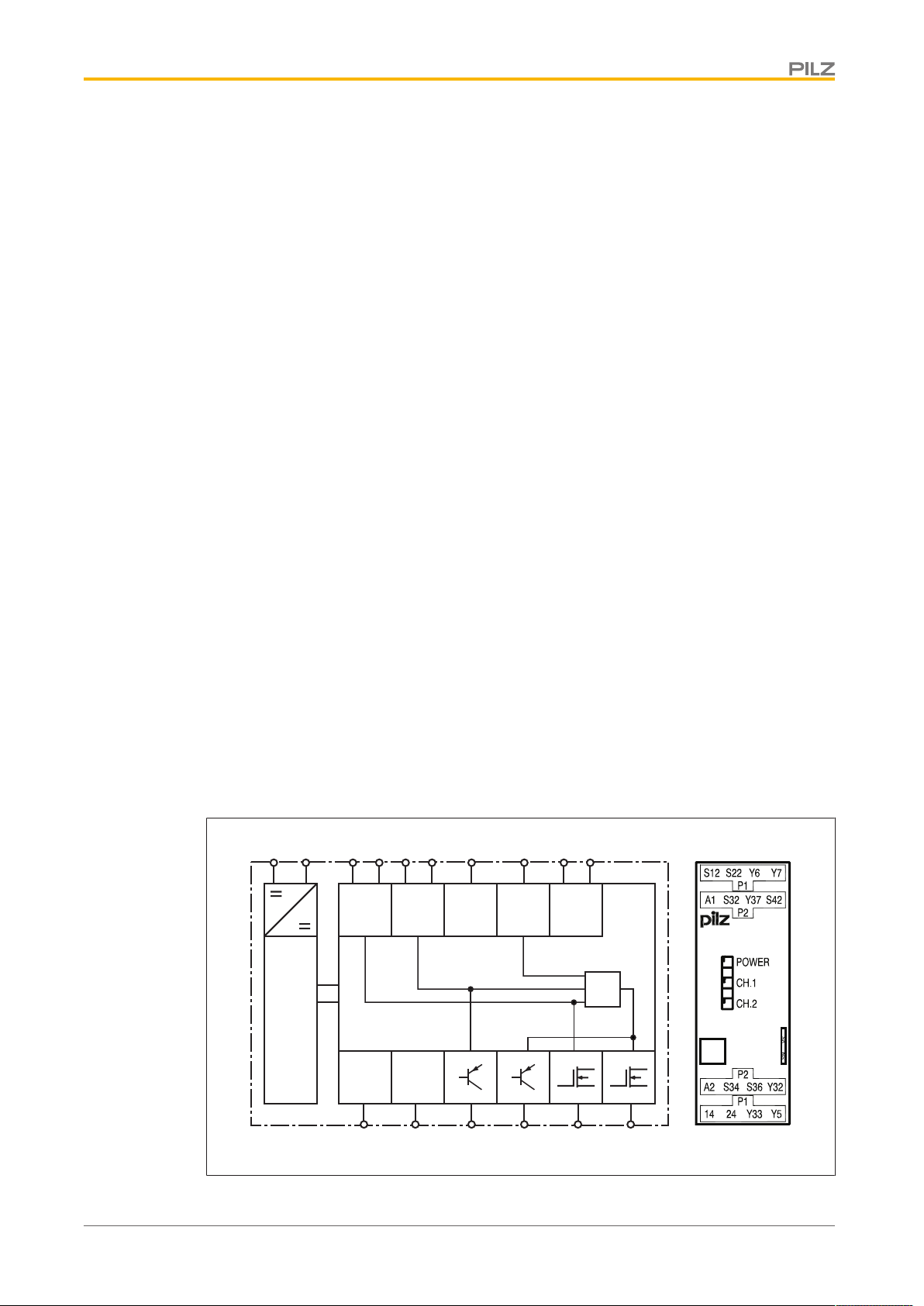
PNOZ e8.1p
Input
PLIDdys
Input
Feedback
Diagnostic
Power
Test
Pulse
Output
S12
S36
Y6
Y5
14 24Y32
A1 A2
S22
Start
S34
Input
S32
S42
Y33Y37
Y7
&
PNOZ e8.1p
Unit features
} Outputs using semiconductor technology:
– 2 safety outputs
– 2 auxiliary outputs
– 1 test pulse output
} Connection options:
– PLID d1
– E-STOP pushbuttons
– Safety gate limit switches
– Start button
– Proximity switch
– Position switch with N/C / N/C combination
} To process signals from output signal switching devices (OSSDs) on light grids
} LED display for:
– Supply voltage
– Switch state of safety outputs
} Feedback loops for monitoring external contactors
Safety features
The relay meets the following safety requirements:
} The circuit is redundant with built-in self-monitoring.
} The safety device remains effective in the case of a component failure.
} The safety outputs are tested periodically using an off-test.
Block diagram/terminal configuration
Operating Manual PNOZ e8.1p
1002226-EN-06
8
Page 9

PNOZ e8.1p
Function description
When supply voltage is applied and the set operating mode is detected (initialisation
phase), the "POWER" LED is lit. The unit is ready for operation when the feedback loops
are closed.
} Input circuit S12, S22 is closed (e.g. E-STOP pushbutton not operated):
– The LED "CH.1" is lit.
– There is a high signal at safety output 14, the unit is active.
} Input circuit S12, S22 is opened (e.g. E-STOP pushbutton operated):
– The LEDs "CH.1" and "CH.2" go out.
– There is a low signal at safety outputs 14 and 24 and auxiliary output Y32.
Input circuit S32, S42 is AND-linked with input circuit S12, S22 and PLIDdys input S36. The
result of the logic operation can be viewed through safety output 24 and auxiliary output
Y32. If
} Input circuit S12, S22 is closed (e.g. E-STOP pushbutton not operated)
and
} Input circuit S32, S42 is closed (e.g. safety gate closed)
and
} PLID d1 is connected to PLIDsys input S36, the input circuit and the contact (E-STOP
pushbutton or start button) are closed and the cable routing is error-free, then
– The LED "CH.2" is lit and
– There is a high signal at safety outputs 14 and 24 and auxiliary output Y32. The unit
is active.
} Input circuit S32, S42 is opened (e.g. safety gate opened), then
– The LED "CH.2" goes out and
– There is a low signal at safety output 24 and auxiliary output Y32.
Auxiliary output Y33 indicates the status of input circuit S32, S42. There is a high signal at
the auxiliary output if the input circuit S32, S42 is closed (e.g. safety gate closed).
Feedback loop
Before a safety output is switched on, a test is run to establish whether the contacts at
feedback loop inputs Y6 and Y7 are closed. If a contact is open, an error is detected and
LEDs CH.1 and CH.2 will flash alternately. It will not be possible to switch the unit back on
until the feedback loops are closed and the safety function has been reset.
The feedback loop contacts are also checked when the signal at the output changes from
high to low. After this signal change, the contacts at the feedback loop inputs must close
within 150 ms. If a contact is still open after 150 ms has elapsed, an error is detected and is
displayed as a flashing code 1,8 (see Faults – Interference [ 17]). It will not be possible
to switch the unit back on until the error has been rectified and the supply voltage has been
switched off and then on again.
Operating Manual PNOZ e8.1p
1002226-EN-06
9
Page 10

PNOZ e8.1p
Operating modes
} Single-channel operation: Input wiring in accordance with EN 60204, no redundancy in
the input circuit; earth faults in the input circuit and start circuit are detected.
} Dual-channel operation: Redundant input circuit; earth faults in the input circuit and
start circuit are detected.
} Automatic start: Unit is active once the input circuit has been closed.
} Monitored start: Unit is not active until the start button has been operated and then re-
leased.
} Increase in the number of available contacts by connecting contact expander modules
or external contactors/relays.
Selecting sensors
When selecting sensors, you must comply with the technical details of the input circuits on
the PNOZelog units.
Installation
CAUTION!
Electrostatic discharge can damage components on the safety system!
Ensure against discharge before touching the safety system, e.g. by touching an earthed, conductive surface or by wearing an earthed armband.
} The unit should be installed in a control cabinet with a protection type of at least IP54.
} Use the notch on the rear of the unit to attach it to a DIN rail (35 mm).
} When installed vertically: Secure the unit by using a fixing element (e.g. retaining
bracket or end angle).
NOTICE
If you are connecting several units logically, please note the guidelines in
the section entitled Logic connection between several units [ 15].
Operating Manual PNOZ e8.1p
1002226-EN-06
10
Page 11

PNOZ e8.1p
R
lmax
Rl / km
I
max
=
Wiring
Please note:
} Information given in the "Technical details [ 22]" must be followed.
} Use copper wire that can withstand 60/75°C.
} Calculation of the max. cable length l
R
= max. overall cable resistance (see Technical details [ 22])
lmax
Rl/km = cable resistance/km
} Cables that have to be laid outside the control cabinet must be protected from mechan-
ical damage, e.g. by installing them in a conduit.
} The unit and the input circuits must always be supplied by a single power supply.
} Safety outputs 14 and 24 should exclusively be used for safe applications.
} The safety outputs must not be connected to control inputs.
} To suppress the pulse on switching off at safety outputs 14 and 24, use the terminal
block with filter (see Order reference [ 26]).
} You must comply with the idling capacity at safety outputs 14 and 24 (see Technical
details [ 22]).
} Only contactors with positive-guided contacts should be used for safety functions.
} Outputs Y32 and Y33 are auxiliary outputs, e.g. for communication with a PLC or text
display.
} Do not use auxiliary outputs Y32 and Y33 for safety circuits!
} Use freewheel diodes to drive inductive loads (e.g. contactors or relays) with the safety/
auxiliary outputs.
} When connecting magnetically operated, reed proximity switches, ensure that the max.
peak inrush current (on the input circuit) does not overload the proximity switch.
} The power supply must comply with the regulations for extra low voltages with protect-
ive electrical separation (SELV, PELV) in accordance with VDE 0100, Part 410.
} Ensure the wiring and EMC requirements of EN 60204-1 are met.
} Terminal Y5 is provided for Pilz-internal diagnostic purposes.
} Where one line is to be monitored, only use one PNOZ e8.1p and one PLID d1. Route
the line so that it is protected.
in the input circuit:
max
Operating Manual PNOZ e8.1p
1002226-EN-06
11
Page 12

PNOZ e8.1p
A1
F1
A2
L+
L-
A1
A2 S12
S22
24 V DC
GND
A1
A2 S32
S42
24 V DC
GND
Preparing for operation
Supply voltage
Supply voltage AC DC
Input circuit
Evaluation device for PLID d1:
The PLID d1 should be wired as described in the operating manual for PLID d1.
Input circuit Input circuit S12, S22 Input circuit S32, S42
Single-channel
Dual-channel (without detection of shorts across contacts)
Light guard or safety switch,
detection of shorts across
contacts via ESPE
The E-STOP pushbutton and safety gate switch symbolise a trigger element with N/C / N/C
combination.
Input circuit Input circuit S36, A2
PLID d1
Connection example with
N/C contact (continuous
test)
PLID d1
Connection example with
N/O contact (manual test)
Operating Manual PNOZ e8.1p
1002226-EN-06
12
Page 13

PNOZ e8.1p
CAUTION!
A short circuit on the pushbutton or on the supply line to the pushbutton is
not monitored!
Use appropriate measures to prevent a short circuit on the pushbutton.
Start circuit/feedback loop
Terminals Y6 and Y7 are used to connect the feedback loops and also to define the start
behaviour.
} The Y6 terminal is used to
– Determine the start behaviour for input circuit S12, S22 and
– To connect the feedback loop for safety output 14.
} The Y7 terminal is used to
– Determine the start behaviour for input circuit S32, S42 and
– Connect the feedback loop for safety output 24.
Start behaviour Input circuit S12, S22 Input circuit S32, S42
Automatic start
Monitored start
Feedback loop unconnected:
If you do not wish to connect any contacts to the feedback loop, replace the contacts at Y6 /
Y7 with a bridge, depending on the required start behaviour.
NOTICE
With automatic start
The unit starts up automatically when the safeguard is reset, e.g. when the
E-STOP pushbutton is released. Use external circuit measures to prevent
an unexpected restart.
Operating Manual PNOZ e8.1p
1002226-EN-06
13
Page 14

PNOZ e8.1p
Application example
Fig.: Safe line inspection with PLID d1 and AND-link with PNOZ e3.1p
Operating Manual PNOZ e8.1p
1002226-EN-06
14
Page 15

PNOZ e8.1p
Logic connection between several units
Units from the PNOZelog product range can be logically connected to each other and to
units from the PNOZmulti product range. On the PNOZelog, input S35 is intended for the
logic OR connection and input S36 for the logic AND connection. Safety outputs 14 and 24
on the PNOZelog are suitable for logic connections.
When linking several units logically, please note:
} When PNOZelog units are linked logically to each other, a safety output from a
PNOZelog unit may be connected to logic inputs from one or more PNOZelog units.
} When linking PNOZelog units logically to PNOZmulti units
– a cascading output from PNOZmulti units may be connected to logic inputs on
PNOZelog units
or
– a safety output from PNOZelog units may be connected to cascading inputs on
PNOZmulti units.
} The unit with the lowest SIL/PL value determines the SIL/PL value of the entire circuit.
} PNOZ e1p, PNOZ e8.1p: These units do not have logic inputs. Their safety outputs can
be used to logically link the units to the logic inputs of other PNOZelog units or to the
cascading inputs from PNOZmulti units.
} Safety outputs from the PNOZ e1p are suitable for logic connections from unit version
3.0.
} Each safety output on a PNOZelog unit that is connected to the load may also be con-
nected to the logic inputs of a maximum of four PNOZelog units.
} Up to 50 logic inputs from PNOZelog units can be connected to safety outputs with no
load.
} Logically linking the units leads to delays when switching on and off (see on-delay and
response time in the Technical details [ 22]). These are added up with each unit
that is logically linked.
} Install all the logically linked units in the same control cabinet or ensure that faults re-
garding the units' connection are excluded, e.g. via protected installation of the connection cables.
} All linked units must be connected to the same supply voltage.
Operating Manual PNOZ e8.1p
1002226-EN-06
15
Page 16

PNOZ e8.1p
Operation
NOTICE
The safety function should be checked after initial commissioning and each
time the plant/machine is changed. The safety functions may only be
checked by qualified personnel.
INFORMATION
The safety outputs are constantly checked via test pulses. This may generate a humming noise on the connected contactors, which does not affect
the function. The test pulses also mean that, when measured with a multimeter, the voltage at the safety outputs is displayed to be less than it actually is.
The unit detects the set operating mode once supply voltage is applied. During this time
(initialisation phase) the "POWER" LED will flash. The unit is ready for operation when the
"POWER" LED is lit continuously.
LEDs indicate the status and errors during operation:
LED on
LED flashes
Status indicators
POWER
Supply voltage is present, operating mode is detected.
POWER
Initialisation phase
CH.1
There is a high signal at safety output 14.
CH.2
There is a high signal at safety output 24.
Operating Manual PNOZ e8.1p
1002226-EN-06
16
Page 17

PNOZ e8.1p
Faults – Interference
INFORMATION
Supply interruptions lasting longer than 20 ms are detected as an error. The
LEDs indicate an error and the safety outputs carry a low signal. The plant
or machinery driven via the safety outputs will be shut down. The unit can
only be restarted when the supply voltage is switched off for at least 1 s and
then switched on again.
Fault
Fault conditions are indicated by flashing the LEDs. There are faults that are displayed via
periodic flashing (see table "Display of fault conditions") and faults where an error code can
be determined via the number of flashes (see table "Relationship between the number of
flashes and the decimal error code"). These faults are always indicated by three short
flashes at LED CH.1 or CH.2. After a longer pause, the LED will then flash at one second
intervals. The number of LED flashes corresponds to a digit in the error code. The error
code can consist of up to 4 digits. The digits are separated by a longer period without flashing. The entire sequence is constantly repeated.
INFORMATION
Error code 0: 16 flashes
Operating Manual PNOZ e8.1p
1002226-EN-06
17
Page 18

PNOZ e8.1p
I
IV
II
Display of fault conditions
LED Fault Remedy
LEDs unlit Supply voltage is missing,
too low, wrongly connected
POWER flashes Unknown operating mode,
initialisation phase, start not
executed
CH.1 or CH.2 flash a code Error coding, see table "Er-
ror code [ 20]"
CH.1 and CH.2 flash alternately
1.) Feedback loop open on
start-up
2.) Only one channel of the
input circuit is open or is partially operated
Examples
Error code 1, 3:
LED CH.1 or CH.2 flashes
} 3 times, short
} Pause
} Once for one second
} Pause
} 3 times, for one second each
Connect supply voltage: A1 +24 VDC and A2 - 0 VDC
Permitted voltage range:
19.2 ... 30VDC
Depending on operating
mode: Press start button or
perform start-up test
See table "Error
code [ 20]"
1.) Close feedback loop,
open input circuit, start unit
again
2.) Open both input circuit
channels or activate and
then clear the safety mat
Error code 1:
LED CH.1 or CH.2 flashes
} 3 times, short
} Pause
} Once for one second
Operating Manual PNOZ e8.1p
1002226-EN-06
18
Page 19

PNOZ e8.1p
I
IV
III
II
Error code 1, 0:
LED CH.1 or CH.2 flashes
} 3 times, short
} Pause
} Once for one second
} Pause
} 16 times, for one second each
I Code for error message
II Code for 1st digit
III Code for 2nd digit
IV Code for error message repeated
The table below shows the relationship between the number of flashes and the error code.
The key to the error codes is described in the Error coding table.
Number of
1 2 3 4 5 6 7 8 9 10 11 12 13 14 15 16
flashes
Decimal er-
1 2 3 4 5 6 7 8 9 10 11 12 13 14 15 0
ror code
Operating Manual PNOZ e8.1p
1002226-EN-06
19
Page 20

PNOZ e8.1p
Error coding
INFORMATION
Each time a fault is rectified, switch the supply voltage off for at least 1 s
and then switch it back on.
Decim
al error
code Number of flashes Description Remedy
1
3x short – 1x long
– 3x short
2
3x short – 2x long
– 3x short
3 3x short – 3x long
– 3x short
4
3x short – 4x long
– 3x short
…
9
…
3x short – 9x long
– 3x short
10
3x short – 10x long
– 3x short
…
1, 0
…
3x short – 1x long
– 16x long – 3x short
1, 1
3x short – 1x long
– 1x long – 3x short
1, 9
3x short – 1x long
– 9x long – 3x short
Faulty wiring, short circuit Wiring error at start input, input cir-
cuits, feedback loop or programming
input
Operating mode changed during
operation
In the initialisation phase, short
Check wiring for the operating mode
and rectify fault
Rectify wiring error at terminals 14, 24
circuit between the safety outputs and +24 VDC
During operation, short circuit
Rectify wiring error at terminals 14, 24
between the safety outputs and
+24 VDC
10.1
3x short – 10x long
– 1x long – 3x short
14.5
3x short – 14x long
– 5x long – 3x short
1, 2
3x short – 1x long
– 2x long – 3x short
1, 3
3x short – 1x long
– 3x long – 3x short
1, 12
3x short – 1x long
– 12x long – 3x short
1, 13
3x short – 1x long
– 13x long – 3x short
1, 4 3x short – 1x long
– 4x long – 3x short
Operating Manual PNOZ e8.1p
1002226-EN-06
During operation, short circuit
between the safety outputs and
0 VDC or UB<19.2 VDC
Operating mode changed during
operation
Rectify wiring error at terminals 14, 24;
Keep within the supply voltage range
of 19.2 ... 30 VDC
Check wiring for the operating mode
and rectify fault
20
Page 21

PNOZ e8.1p
Decim
al error
code Number of flashes Description Remedy
1, 5 3x short – 1x long
– 5x long – 3x short
1, 6
3x short – 1x long
– 6x long – 3x short
1, 7
3x short – 1x long
– 7x long – 3x short
1, 8
3x short – 1x long
– 8x long – 3x short
1, 11
3x short – 1x long
– 11x long – 3x short
1, 10 3x short – 1x long
– 10x long – 3x short
5, 10 3x short – 5x long
– 10x long – 3x short
8, 1 3x short – 8x long
– 1x long – 3x short
8, 2
3x short – 8x long
– 2x long – 3x short
8, 3
3x short – 8x long
– 3x long – 3x short
Unexpected status at S36 Check wiring at terminal S36
Wiring of operating mode “with
Rectify wiring error at input circuits
detection of shorts across contacts” faulty
1. Maximum time of feedback
loop monitoring exceeded
2. PNOZe6.1p, PNOZe6vp:
External feedback loop
1. Check contactor for contact welding
2. No user remedy possible. Change
the unit.
closed, but internal feedback
loop faulty
Open circuit Check safety mat wiring
UB<19.2VDC Keep within the supply voltage range
of 19.2 ... 30 VDC
Invalid operating mode Check wiring for the operating mode
and rectify fault
Supply interrupted, possibly
caused by a short to earth
Rectify wiring error at terminal A1 or
check supply voltage
14, 13
3x short – 14x long
– 13x long – 3x short
2, 0, 0
3x short – 2x long
– 16x long – 16x long
– 3x short
2, 0, 1
3x short – 2x long
– 16x long – 1x long
– 3x short
2, 0, 2 3x short – 2x long
– 16x long – 2x long
– 3x short
2, 0, 3 3x short – 2x long
– 16x long – 3x long
– 3x short
UB<19.2VDC Keep within the supply voltage range
of 19.2 ... 30 VDC
In the initialisation phase, short
Rectify wiring error at terminals 14, 24
circuit between the safety outputs and +24 VDC
UB<19.2VDC Keep within the supply voltage range
of 19.2 ... 30 VDC
Operating Manual PNOZ e8.1p
1002226-EN-06
21
Page 22

PNOZ e8.1p
Dimensions in mm
* With spring-loaded terminals
Technical details
General 774198 784198
CE, EAC (Eurasian), TÜV, cULus
Approvals
Electrical data 774198 784198
Supply voltage
Voltage 24 V 24 V
Kind DC DC
Voltage tolerance -15 %/+10 % -15 %/+10 %
Output of external power supply
(DC) at no load 3 W 3 W
Residual ripple DC 20 % 20 %
Duty cycle 100 % 100 %
External unit fuse protection F1
max. 6 A slow/10 A quick 6 A slow/10 A quick
Inputs 774198 784198
Voltage at
Input circuit DC 24 V 24 V
Start circuit DC 24 V 24 V
Feedback loop DC 24 V 24 V
Logic input 24 V 24 V
Current at
Input circuit DC 5 mA 5 mA
Start circuit DC 5 mA 5 mA
Feedback loop DC 5 mA 5 mA
Logic input 5 mA 5 mA
Listed
CE, EAC (Eurasian), TÜV, cULus
Listed
Operating Manual PNOZ e8.1p
1002226-EN-06
22
Page 23

PNOZ e8.1p
Inputs 774198 784198
Max. overall cable resistance Rlmax
Start circuit and feedback loop 1.000 Ohm 1.000 Ohm
Input circuit, single-channel 1.000 Ohm 1.000 Ohm
Input circuit, dual-channel 2.000 Ohm 2.000 Ohm
Max. line capacitance 450 nF 450 nF
Semiconductor outputs 774198 784198
Overall performance ext. loading,
semiconductor 80 W 80 W
Number of safety outputs
Instantaneous 2 2
Number of auxiliary outputs 2 2
Number of test pulse outputs 1 1
Switching capability, 2 safety outputs under load
Current at UB ≤ 26.5 V 1,5 A 1,5 A
Power at UB ≤ 26.5 V 40 W 40 W
Switching capability, 1 safety output under load
Current at UB ≤ 26.5 V 2 A 2 A
Power at UB ≤ 26.5 V 50 W 50 W
Max. line capacitance at the outputs without load 2 nF 2 nF
Voltage auxiliary and test pulse
outputs 24 V 24 V
Current auxiliary and test pulse
outputs 0,5 A 0,5 A
Times 774198 784198
Switch-on delay
After power on 3 s 3 s
With automatic start typ. 60 ms 60 ms
With automatic start max. 210 ms 210 ms
With monitored start typ. 120 ms 120 ms
With monitored start max. 260 ms 260 ms
Logic inputs typ. 150 ms 150 ms
Logic inputs max. 200 ms 200 ms
Response time tr semiconductor
outputs
Via input circuit max. 35 ms 35 ms
Via logic input max. 50 ms 50 ms
Maximum time of feedback loop
monitoring 150 ms 150 ms
Supply interruption before de-energisation 20 ms 20 ms
Simultaneity, channel 1 and 2 max. ∞ ∞
Operating Manual PNOZ e8.1p
1002226-EN-06
23
Page 24

PNOZ e8.1p
Environmental data 774198 784198
Climatic suitability EN 60068-2-78 EN 60068-2-78
Ambient temperature
Temperature range -10 - 55 °C -10 - 55 °C
Storage temperature
Temperature range -25 - 70 °C -25 - 70 °C
Climatic suitability
Humidity 93 % r. h. at 40 °C 93 % r. h. at 40 °C
Condensation during operation Not permitted Not permitted
EMC EN 60947-5-1, EN 61000-6-2, EN
61000-6-4, EN 61326-3-1
EN 60947-5-1, EN 61000-6-2, EN
61000-6-4, EN 61326-3-1
Vibration
In accordance with the standard EN 60068-2-6 EN 60068-2-6
Frequency 10 - 55 Hz 10 - 55 Hz
Amplitude 0,35 mm 0,35 mm
Airgap creepage
In accordance with the standard EN 60947-1 EN 60947-1
Overvoltage category III III
Pollution degree 2 2
Rated insulation voltage 30 V 30 V
Rated impulse withstand voltage 0,8 kV 0,8 kV
Protection type
Housing IP40 IP40
Terminals IP20 IP20
Mounting area (e.g. control cab-
inet) IP54 IP54
Mechanical data 774198 784198
Mounting position Any Any
Material
Bottom PPO UL 94 V0 PPO UL 94 V0
Front ABS UL 94 V0 ABS UL 94 V0
Top PPO UL 94 V0 PPO UL 94 V0
Connection type Screw terminal Spring-loaded terminal
Mounting type plug-in –
Conductor cross section with screw
terminals
1 core flexible 0,25 - 2,5 mm², 24 - 12 AWG –
2 core with the same cross sec-
tion, flexible with crimp connect-
ors, no plastic sleeve 0,25 - 1 mm², 24 - 16 AWG –
2 core with the same cross sec-
tion, flexible without crimp con-
nectors or with TWIN crimp con-
nectors 0,2 - 1,5 mm², 24 - 16 AWG –
Torque setting with screw terminals 0,5 Nm –
Conductor cross section with
spring-loaded terminals: Flexible
with/without crimp connector – 0,2 - 1,5 mm², 24 - 16 AWG
Operating Manual PNOZ e8.1p
1002226-EN-06
24
Page 25

PNOZ e8.1p
Mechanical data 774198 784198
Spring-loaded terminals: Terminal
points per connection – 2
Stripping length with spring-loaded
terminals – 8 mm
Dimensions
Height 94 mm 101 mm
Width 22,5 mm 22,5 mm
Depth 121 mm 121 mm
Weight 130 g 125 g
Where standards are undated, the 2017-01 latest editions shall apply.
Safety characteristic data
NOTICE
You must comply with the safety-related characteristic data in order to
achieve the required safety level for your plant/machine.
Operating
Mode
EN ISO
13849-1:
2015
PL
EN ISO
13849-1:
2015
Category
EN 62061
SIL CL
EN 62061
PFHD [1/h]
IEC 61511
SIL
IEC 61511
PFD
EN ISO
13849-1:
2015
TM [year]
SC output
via PLIDdys PL d Cat. 2 SIL CL 2 8,02E-09 SIL 2 4,55E-04 20
SC output
via 2-ch. input circuit PL e Cat. 4 SIL CL 3 3,44E-09 SIL 3 4,53E-05 20
All the units used within a safety function must be considered when calculating the safety
characteristic data.
INFORMATION
A safety function's SIL/PL values are not identical to the SIL/PL values of
the units that are used and may be different. We recommend that you use
the PAScal software tool to calculate the safety function's SIL/PL values.
Operating Manual PNOZ e8.1p
1002226-EN-06
25
Page 26

PNOZ e8.1p
Remove plug-in terminals
Procedure: Insert the screwdriver into the housing recess behind the terminal and lever the
terminal out.
Do not remove the terminals by pulling the cables!
Order reference
Product
Product type Features Connection type Order no.
PNOZ e8.1p 24 VDC Screw terminals 774 198
PNOZ e8.1p C 24 VDC Spring-loaded terminal 784 198
PLID d1 24 VDC Screw terminals 774 260
PLID d1 C 24 VDC Spring-loaded terminal 784 260
Accessories
Product type Features Order no.
Terminal block filter 1 Terminal block with filter for 3-10 kOhm load range 774 195
Terminal block filter 2 Terminal block with filter for 10-30 kOhm load range 774 196
Operating Manual PNOZ e8.1p
1002226-EN-06
26
 Loading...