

Page 1

SERVICE STATION MANUAL
633779 ÷ 633786
X8 400 Euro 3
Page 2

SERVICE STATION
MANUAL
X8 400 Euro 3
The descriptions and illustrations given in this publication are not binding. While the basic specifications
as described and illustrated in this manual remain unchanged, PIAGGIO-GILERA reserves the right, at
any time and without being required to update this publication beforehand, to make any changes to
components, parts or accessories, which it considers necessary to improve the product or which are
required for manufacturing or construction reasons.
Not all versions shown in this publication are available in all countries. The availability of single versions
should be checked at the official Piaggio sales network.
"© Copyright 2005 - PIAGGIO & C. S.p.A. Pontedera. All rights reserved. Reproduction of this publication
in whole or in part is prohibited."
PIAGGIO & C. S.p.A. - Q.C.S./After sales V.le Rinaldo Piaggio, 23 - 56025 PONTEDERA (Pi)
www.piaggio.com
Page 3
SERVICE STATION MANUAL
X8 400 Euro 3
This service station manual has been drawn up by Piaggio & C. Spa to be used by the workshops of
Piaggio-Gilera dealers. It is assumed that the user of this manual for maintaining and repairing Piaggio
vehicles has a basic knowledge of mechanical principles and vehicle repair technique procedures. Any
significant changes to vehicle characteristics or to specific repair operations will be communicated by
updates to this manual. Nevertheless, completely satisfactory work cannot be carried out without the
necessary equipment and tools. It is therefore advisable to read the sections of this manual relating to
appropriate tools, along with the appropriate tool catalogue.
N.B. Provides key information to make the procedure easier to understand and carry out.
CAUTION Refers to specific procedures to carry out for preventing damages to the vehicle.
WARNING Refers to specific procedures to carry out to prevent injuries to the repairer.
Personal safety Failure to completely observe these instructions will result in serious risk of personal
injury.
Safeguarding the environment Sections marked with this symbol indicate the correct use of the vehicle
to prevent damaging the environment.
Vehicle intactness The incomplete or non-observance of these regulations leads to the risk of serious
damage to the vehicle and sometimes even the invalidity of the guarantee.
Page 4
Page 5
INDEX OF TOPICS
CHARACTERISTICS CHAR
TOOLING TOOL
MAINTENANCE MAIN
ELECTRICAL SYSTEM ELE SYS
ENGINE FROM VEHICLE ENG VE
ENGINE ENG
INJECTION INJEC
SUSPENSIONS SUSP
BRAKING SYSTEM BRAK SYS
COOLING SYSTEM COOL SYS
CHASSIS CHAS
PRE-DELIVERY PRE DE
TIME TIME
Page 6

INDEX OF TOPICS
CHARACTERISTICS CHAR
Page 7

X8 400 Euro 3 Characteristics
This section describes the general specifications of the vehicle.
Rules
This section describes general safety rules for any maintenance operations performed on the vehicle.
Safety rules
•
Should it be necessary to keep the engine running while servicing, make sure that the area
or room is well ventilated, and use special exhaust fans, if required. never let the engine run
in an enclosed area. Exhaust fumes are toxic.
•
The battery electrolyte contains sulphuric acid. Protect your eyes, clothes and skin. Sulphuric acid is highly corrosive; in the event of contact with your eyes or skin, rinse thoroughly
with abundant water and seek immediate medical attention.
•
The battery produces hydrogen, a gas that can be highly explosive. Do not smoke and avoid
sparks or flames near the battery, especially when charging it.
•
Fuel is highly flammable, and in some conditions it can be explosive. Do not smoke in the
working area, and avoid open flames or sparks.
•
Clean the brake pads in a well ventilated environment, directing the compressed air jet so
as to not inhale the dust produced by the wear of the friction material. Even though the latter
contains no asbestos, dust inhalation is harmful.
Maintenance rules
•
Use original PIAGGIO spare parts and lubricants recommended by the Manufacturer. Nonoriginal or non-conforming spares may damage the vehicle.
•
Use only the special tools designed for this scooter.
•
Always use new gaskets, sealing rings and split pins upon reassembly.
•
After removal, clean the components using non-flammable or low fire-point solvent. Lubricate all the work surfaces except the tapered couplings before refitting.
•
After reassembly, check that all components have been installed properly and that they are
in good working order.
•
For removal, overhaul and reassembly operations use only tools provided with metric measures. Metric bolts, nuts and screws are not interchangeable with coupling members with
English measurement. Using unsuitable coupling members and tools may damage the
scooter.
•
Should any interventions to the scooter electrical system be required, check that the electrical connections - especially earth and battery connections - have been implemented
properly.
CHAR - 7
Page 8
Characteristics X8 400 Euro 3
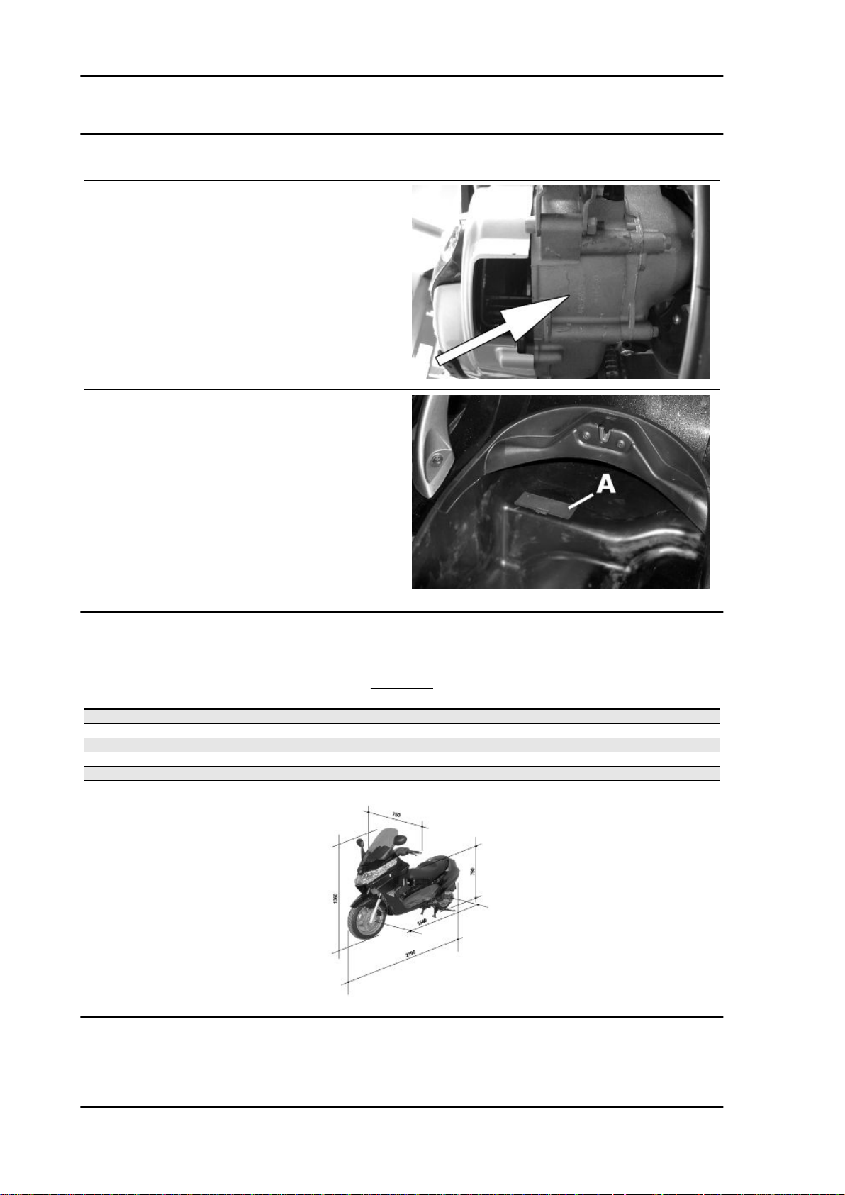
Vehicle identification
Chassis prefix
ZAPM52100÷1001
Engine prefix
M521M÷1001
Dimensions and mass
Specification
Kerb weight 206 kg
Overall width 750 mm
Overall length 2190 mm
Wheelbase 1540 mm
Saddle height 790 mm
Overall height 1360 mm
WEIGHT
Desc./Quantity
CHAR - 8
Page 9

X8 400 Euro 3 Characteristics
Engine
ENGINE
Specification Desc./Quantity
Engine single-cylinder, four-stroke
Bore x stroke 85.8 X 69 mm
Cubic capacity 399 cm³
Compression ratio 10.6 ± 0.5 : 1
Timing system Single overhead camshaft with integrated tone wheel, control
Valve clearance: intake 0.15 mm (when cold)
Valve clearance: discharge 0.15 mm (when cold)
Valve clearance adjustment By threaded adjuster on the rockers
Engine idle speed 1500 ± 50 rpm
Air filter sponge, impregnated with mixture (50% petrol and 50% oil)
CO % value (measured at the intake manifold) 1 - 1.5%
Starting system Electric starter system with freewheel.
Lubrication By trochoidal pump (inside the crankcase), pressure adjust-
Lubrication pressure 4 bar
Minimum allowed (at 100° C) 0.8 bar
Fuel supply Electronic injection system with electric fuel pump, Ø 38 mm
Maximum power (to the crankshaft) 24.5 kW at 7250 rpm
Maximum torque (to the crankshaft) 36 Nm at 5500 rpm
Cooling system Fluid circulation through a motor-driven pump, 3-way thermo-
from flywheel side chain, 4 valves and automatic start-up valve
lifting device.
ment by-pass and oil filter.
throttle body and single injector.
stat and electric fan.
Transmission
Specification
Transmission With automatic expandable pulley variator with torque server,
Capacities
Specification
Engine oil (empty) 1.7 lt.
Engine oil (at oil and filter change) 1.5 lt.
Fuel tank capacity Tank capacity: ~12 l (approximate value)
Cooling system approx. 1.8 litres
Electrical system
Specification
Electronic ignition inductive, high efficiency integrated with the injection system,
Spark plug NGK CR7EKB
Spark plug CHAMPION RG6YC
Generator Three-phase alternating current
TRANSMISSIONS
Desc./Quantity
V belt, automatic clutch, gear reduction unit and transmission
housing with forced air circulation cooling.
CAPACITY
Desc./Quantity
Rear hub approx. 250 cc.
ELECTRICAL SYSTEM
Desc./Quantity
with variable timing and separate HV coil.
Battery Dry-cell lead-acid battery, 12V-14Ah
CHAR - 9
Page 10
Characteristics X8 400 Euro 3
Frame and suspensions
FRAME AND SUSPENSIONS
Specification Desc./Quantity
Chassis Welded steel pipes with pressed sheet metal stiffening
Front suspension Double effect hydraulic telescopic fork with Ø 35 mm stems and
Front fork max. stroke 104 mm
Rear suspension Engine with swinging fork attached to the frame by means of
pin backwards with connections for double brake calliper
an arm with one degree of freedom and a pair of double effect
hydraulic shock absorbers with 4 adjustable preload positions.
Brakes
BRAKES
Specification Desc./Quantity
Front brake Ø 240mm double disk brake with hydraulic control activated by
Rear brake Ø 240 mm disc brake with hydraulic control activated by han-
the handlebar right-hand lever.
dlebar left lever.
Wheels and tyres
WHEELS AND TYRES
Specification
Tyre pressure (cold) front 2.1 bar
Tyre pressure (cold) rear 2.3 bar (2.5 bar with passenger)
Front wheel rim Die-cast aluminium alloy, 3.50"x14''
Rear wheel rim Die-cast aluminium alloy 4.50"x14"
Front tyre Tubeless 120/70 - 14'' - Michelin Gold Standard M/C 55S
Rear tyre Tubeless 140/70 - 14'' - Michelin Gold Standard M/C 68S
N.B.
CHECK AND ADJUST TYRE PRESSURE WITH TYRES AT AMBIENT TEMPERATURE. ADJUST
PRESSURE ACCORDING TO THE WEIGHT OF RIDER AND ACCESSORIES.
CAUTION
IT IS MANDATORY TO ADOPT EXCLUSIVELY "S" CLASS TYRES, WHICH GUARANTEE CORRECT VEHICLE PERFORMANCE AT THE DIFFERENT SCOOTER SPEEDS. USING ANY OTHER
TYRE MAY RESULT IN VEHICLE INSTABILITY. IT IS ADVISABLE TO USE TYRE TYPES RECOMMENDED BY PIAGGIO.
Desc./Quantity
Tightening Torques
CHAR - 10
FRAME
Name
Electric pump locking ring nut 20
Torque in Nm
BRAKE SYSTEM
Name
Brake calliper coupling 20 - 24
Front brake disc mounting 5 ÷ 6 •
Torque in Nm
Page 11

X8 400 Euro 3 Characteristics
Name Torque in Nm
Rear brake disc mounting 11 ÷ 13
Front brake calliper mounting on fork 20 ÷ 25
Rear calliper support on crankcase retainer 20 ÷ 25
Pipe / brake calliper coupling 20 ÷ 25
Pipe / brake pump coupling 20 ÷ 25
Front brake pipe splitter coupling 20 ÷ 25
• Lock with Loctite 243 medium strength threadlock
FRONT SUSPENSION
Name Torque in Nm
Front wheel axle 45 ÷ 50
Holding torque of lower ring nut 20 ÷ 25
Fork stem mounting to the plate 20 ÷ 25
Steering lower ring nut 10 - 13 **
Upper steering ring nut 36 - 39
Stem upper cap 35 - 55
Fixing screw handlebar to steering tube 45 ÷ 50
Pumping element fixing screw 25 - 35
Safety screw on fork leg 6 ÷ 7
Wheel fastening screws 33 - 37
* tighten and loosen completely. ** tighten and loosen by 90°.
REAR SUSPENSION
Name Torque in Nm
Upper shock absorber clamp 33 ÷ 41
Lower shock absorber clamp 33 ÷ 41
Shock absorber-crankcase attachment bracket 20 ÷ 25
Rear wheel axle 104 ÷ 126
Muffler arm clamping screws 27 ÷ 30
ENGINE ASSEMBLY
Name
Starter motor screws 11 ÷ 13
Torque in Nm
THERMAL GROUP AND TIMING SYSTEM
Name
Spark plug 12 ÷ 14
Head fixing stud bolts ***
Head fixing nuts 10 - 12
Exhaust / intake head fixing nuts 10 - 12
Head lubrication control jet 5 - 7
Coolant temperature sensor: 10 - 12
Lambda probe on exhaust manifold 10 - 12
injector fixing screw 3 ÷ 4
Counterweight screw 7 ÷ 8.5
Tensioner sliding block fixing screw 10 - 14
Rpm timing sensor fixing screw 3 - 4
Valve lifter mass stop bell fixing screws 30 - 35
Inlet manifold screws 11 ÷ 13
Tappet cover fixing screws 7 - 9
Throttle body fixing screws 11 ÷ 13
Head fixing screws 10 - 12
Camshaft retaining bracket screws: 4 ÷ 6
Tightener screw: 5 - 6
Tightener fastening screws: 11 ÷ 13
*** Apply a preliminary torque of 7 Nm in a crossed sequence. - Tighten by 90° in a crossed sequence. - tighten again by 90° in
a criss-crossed sequence.
Torque in Nm
CRANKCASE AND CRANKSHAFT
Name
Countershaft fixing nut 25 ÷ 29
Engine oil filter 12 - 16
Torque in Nm
CHAR - 11
Page 12

Characteristics X8 400 Euro 3
Name Torque in Nm
Engine oil drainage plug 24 ÷ 30
Engine-crankcase coupling screws 11 ÷ 13
Oil pump screws 5 - 6
Gear mounting on crankshaft screws 10 -12
Bulkhead screws for oil pump housing cover 8 - 10
FINAL REDUCTION
Name Torque in Nm
Rear hub cover screws 24 ÷ 27
TRANSMISSION COVER
Name Torque in Nm
Driven pulley nut 92 - 100
driving pulley nut 160 - 175
Anti-vibration roller screw 16.7 ÷ 19.6
M8 retainers for transmission cover 23 ÷ 26
M6 retainer 11 ÷ 13
Anti-vibration roller retainer 17 - 19
Clutch ring nut 65 - 75
Air conveyor screws 11 ÷ 12
Water pump cover screws 3 ÷ 4
External transmission cover screws 7 ÷ 9
Flywheel cover screws 11 - 13
FLYWHEEL COVER
Name
Chain guide sliding block retain plate fastening screws 3 ÷ 4
Flywheel fixing nut 115 - 125
Stator retainers 8 - 10
Blow-by recovery duct fixing screws 3 - 4
Screw fixing freewheel to flywheel 13 ÷ 15
Stator cable harness guide bracket screws 3 - 4
Supporting screws with bulkhead 0.3 - 0.4
Minimum oil pressure sensor 12 ÷ 14
Water pump impeller 4 ÷ 5
LUBRICATION
Name
Oil pump cover screws 0.7 ÷ 0.9
Screws fixing oil pump to crankcase 5 - 6
See also
Refitting
Refitting
Overhaul
Overhaul data
This section provides the main information for scooter servicing.
Torque in Nm
Torque in Nm
Assembly clearances
CHAR - 12
Page 13

X8 400 Euro 3 Characteristics
Cylinder - piston assy.
HEIGHT AT WHICH THE DIAMETER SHOULD BE MEASURED
Specification Desc./Quantity
A 43.2 mm
B 43 mm
CYLINDER- PISTON
Specification Desc./Quantity
Cylinder diameter C 85.8 - +0.018 -0.01 mm
Piston Ø P 85.768 ± 0.014 mm
CYLINDER - PISTON
COUPLING CATEGORIES
Name
Cylinder- Piston A 85.790÷85.797 85.754÷85.761 0.029÷0.043
Cylinder- Piston B 85.797÷85.804 85.761 ÷ 85.768 0.029÷0.043
Cylinder- Piston C 85.804÷85.811 85.768÷85.775 0.029÷0.043
Cylinder- Piston D 85.811÷85.818 85.775÷85.782 0.029÷0.043
CATEGORIES OF COUPLING
N.B.
THE PISTON MUST BE INSTALLED WITH THE ARROW FACING TOWARDS THE EXHAUST SIDE,
THE PISTON RINGS MUST BE INSTALLED WITH THE WORD «TOP» OR THE STAMPED MARK
FACING UPWARDS.
Initials Cylinder Piston Play on fitting
Piston rings
* Fit rings «2» and «3» with the word «TOP» facing upwards.
** Position the openings in the rings as shown here.
*** Value «A» of sealing ring inside the cylinder
**** Ring opening
CHAR - 13
Page 14

Characteristics X8 400 Euro 3
SEAL RINGS
Specification Desc./Quantity
1st compression ring 0.150 ÷0.300
2nd compression ring 0.250 ÷0.500
Oil scraper ring 0.250 ÷0.500
SEAL RINGS
Crankcase - crankshaft - connecting rod
Diameter of crankshaft bearings.
Measure the bearings on both axes x-y.
CRANKSHAFT
Specification
Cat. 1 Standard diameter: 40.020÷40.026
Cat. 2 Standard diameter: 40.026÷40.032
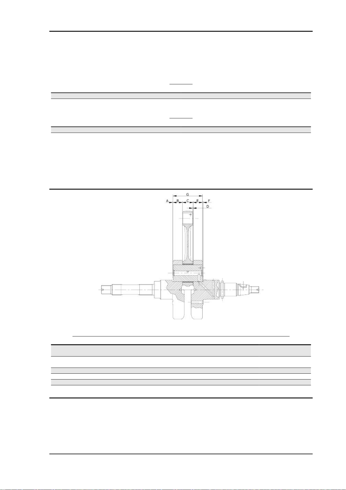
Crankshaft alignment
Specific tooling
020335Y Magnetic support for dial gauge
MAX. ADMISSIBLE DISPLACEMENT
Specification
A = 0.15 mm
B = 0.010 mm
C = 0.010 mm
D = 0.10 mm
Desc./Quantity
Desc./Quantity
Crankcase / countershaft coupling
Besides considering it should match the crankshaft, the crankcase is chosen according to the centre
to centre distance between the seat of the crankshaft and that of the contra-rotating shaft.
Both the centre to centre distance and the pair of gears driving the contra-rotating shaft are divided into
two types (A and B) to be matched (A with A and B with B).
CHAR - 14
Page 15
X8 400 Euro 3 Characteristics
This selection is useful to keep the difference between the working distance of the gears and their
distance without clearance at a given value in order to avoid abnormal noise.
TYPE A
Specification Desc./Quantity
Centre to centre distance of the gears without clearance 76.937 ÷ 76.867
Centre to centre distance on the crankcase 77.022 ÷ 76.992
TYPE B
Specification Desc./Quantity
Centre to centre distance of the gears without clearance 76.907 ÷ 76.837
Centre to centre distance on the crankcase 76.992 ÷ 76.962
The gears with centre to centre distance without clearance between 76.867 and 76.907 are considered
universal and can be fitted to either crankcase type.
Either the pair of gears or the crankcase is identified with the letter referring to the type (on the crankcase, this mark is found at the cylinder mouth, flywheel side).
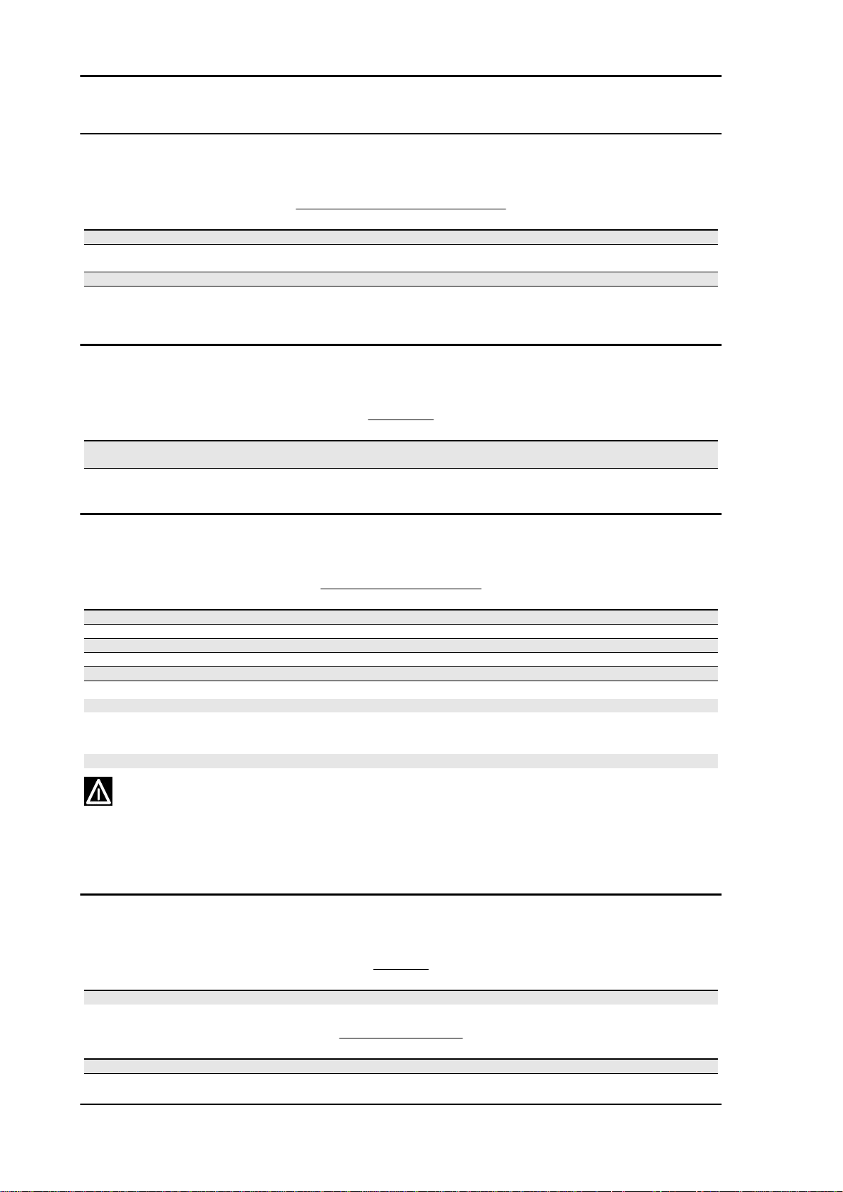
AXIAL CLEARANCE BETWEEN CRANKSHAFT AND CONNECTING ROD
Name
Transmission-side
shoulder
Half-shaft, transmission
side
Connecting rod 22 -0.10 -0.15 C D = 0.20 - 0.50
Flywheel-side shoulder 1.8±0.025 F D = 0.20 - 0.50
Flywheel-side half-shaft 19.6 -0.05 E D = 0.20 - 0.50
Complete crankshaft 65.5 +0.10 -0.05 G D = 0.20 - 0.50
Description Dimensions Initials Quantity
1±0.025 A D = 0.20 - 0.50
20.9 -0.05 B D = 0.20 - 0.50
CHAR - 15
Page 16
Characteristics X8 400 Euro 3
Characteristic
crankshaft / crankcase axial clearance:
0.1 ÷ 0.405 mm
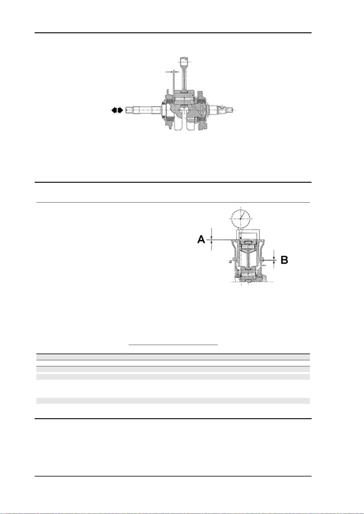
Slot packing system
Shimming system for keeping the compression ratio
DISTANCE «A» IS A PROTRUSION OR RECESS VALUE OF
THE PISTON CROWN WITH RESPECT TO THE CYLINDER
PLANE.
DISTANCE «A» HELPS DETERMINE THE THICKNESS OF
GASKET «B» THAT HAS TO BE FITTED TO THE CYLINDER
HEAD IN ORDER TO RESTORE COMPRESSION RATIO.
BASE GASKET «B» MUST BE THICKER THE MORE THE
PLANE FORMED BY THE PISTON TOP PROTRUDES
FROM THE PLANE FORMED BY THE CYLINDER HEAD. ON
THE OTHER HAND, THE MORE THE PISTON TOP IS RECESSED INTO THE CYLINDER TOP PLANE, THE SMALLER THE GASKET THICKNESS.
Characteristic
Compression ratio
10.6 ± 0.5 : 1
BASE GASKET THICKNESS
Name
«A» MEASURE TAKEN - 0.185 - - 0.10 0.4 ± 0.05
«A» MEASURE TAKEN - 0.10 - + 0.10 0.6 ± 0.05
«A» MEASURE TAKEN + 0.10 ÷ + 0.185 0.8 ± 0.05
N.B.
VALUES INDICATED WITH «-» REFER TO PISTON CROWN RECESSES WITH RESPECT TO THE
CYLINDER PLANE.
N.B.
DISTANCE «A» MUST BE MEASURED WITHOUT ANY GASKET FITTED AT «B»
Measure A Thickness
CHAR - 16
Page 17

X8 400 Euro 3 Characteristics
Products
PRODUCTS
Product Description Specifications
AGIP ROTRA 80W-90 Rear hub oil SAE 80W/90 Oil that exceeds the re-
AGIP FILTER OIL Oil for air filter sponge Mineral oil with specific additives for in-
AGIP CITY HI TEC 4T Engine oil SAE 5W-40, API SL, ACEA A3, JASO MA
AGIP BRAKE 4 Brake fluid FMVSS DOT 4 Synthetic fluid
SPECIAL AGIP PERMANENT fluid coolant Monoethylene glycol-based antifreeze
AUTOSOL METAL POLISH Muffler cleaning paste Specific product for cleaning and polish-
AGIP GP 330 Grease for brake levers, throttle White calcium complex soap-based
AGIP CITY TEC 2T Mixer oil synthetic oil for 2-stroke engines: JASO
quirements of API GL3 specifications
creased adhesiveness
Synthetic oil
fluid, CUNA NC 956-16
ing stainless steel mufflers
spray grease with NLGI 2; ISO-L-XBCIB2
FC, ISO-L-EGD
CHAR - 17
Page 18

INDEX OF TOPICS
TOOLING TOOL
Page 19

X8 400 Euro 3 Tooling
ATTREZZATURA SPECIFICA BUONA
Stores code Description
001330Y Tool for fitting steering seats
001467Y002 Driver for OD 73 mm bearing
001467Y006 Pliers to extract 20 mm bearings
001467Y007 Driver for OD 54-mm bearings
001467Y008 Pliers to extract 17 mm ø bearings
001467Y014 Pliers to extract ø 15-mm bearings
TOOL - 19
Page 20
Tooling X8 400 Euro 3
Stores code Description
001467Y031 Bell
001467Y034 Pliers to extract ø 15-mm bearings
001467Y035 Belle for OD 47-mm bearings
002465Y Pliers for circlips
006029Y Punch for fitting fifth wheel seat on steer-
020004Y Punch for removing fifth wheels from
ing tube
headstock
TOOL - 20
Page 21
X8 400 Euro 3 Tooling
Stores code Description
020055Y Wrench for steering tube ring nut
020150Y Air heater support
020151Y Air heater
020193Y Oil pressure gauge
020201Y Spacer bushing driving tube
020262Y Crankcase splitting strip
020306Y Punch for assembling valve sealing rings
TOOL - 21
Page 22

Tooling X8 400 Euro 3
Stores code Description
020329Y MityVac vacuum-operated pump
020330Y Stroboscopic light to check timing
020331Y Digital multimeter
020333Y Single battery charger
020334Y Multiple battery charger
TOOL - 22
Page 23
X8 400 Euro 3 Tooling
Stores code Description
020335Y Magnetic support for dial gauge
020357Y 32x35-mm Adaptor
020358Y 37x40-mm Adaptor
020359Y 42x47-mm Adaptor
020360Y 52x55-mm Adaptor
020364Y 25-mm guide
020376Y Adaptor handle
020382Y012 bush (valve removing tool)
TOOL - 23
Page 24
Tooling X8 400 Euro 3
Stores code Description
020412Y 15 mm guide
020424Y Driven pulley roller casing fitting punch
020431Y Valve oil seal extractor
020434Y Oil pressure control fitting
020439Y 17 mm guide
TOOL - 24
Page 25

X8 400 Euro 3 Tooling
Stores code Description
020444Y Tool for fitting/ removing the driven pulley
020456Y Ø 24 mm adaptor
020458Y Puller for lower bearing on steering tube
clutch
020459Y Punch for fitting bearing on steering tube
020460Y Scooter diagnosis and tester
020467Y Flywheel extractor
TOOL - 25
Page 26
Tooling X8 400 Euro 3
Stores code Description
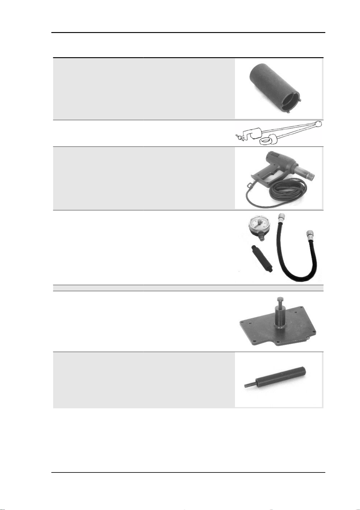
020468Y Piston fitting band
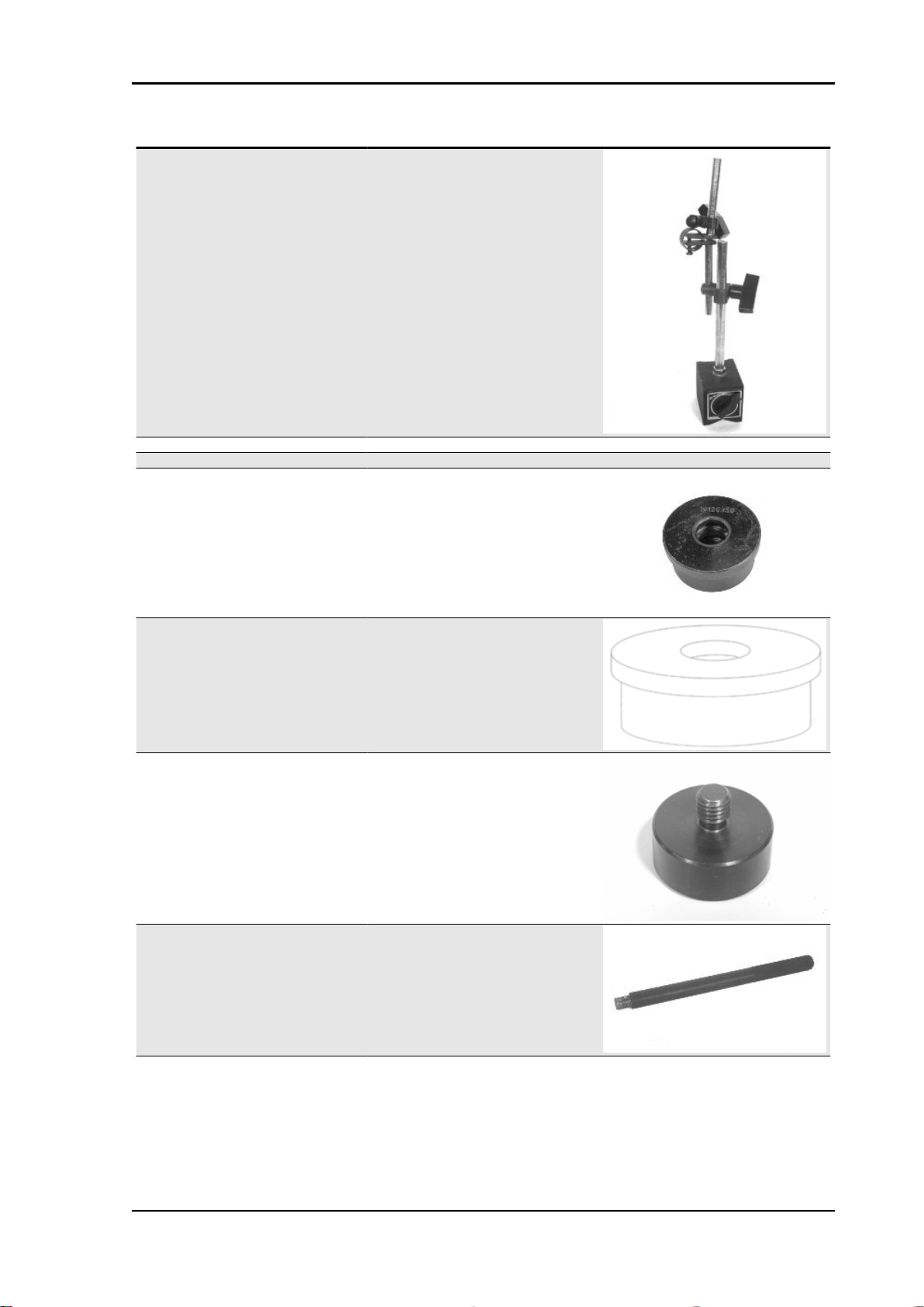
020469Y Reprogramming kit for scooter diagnostic
020470Y Pin retainers installation tool
020471Y Pin for countershaft timing
tester
TOOL - 26
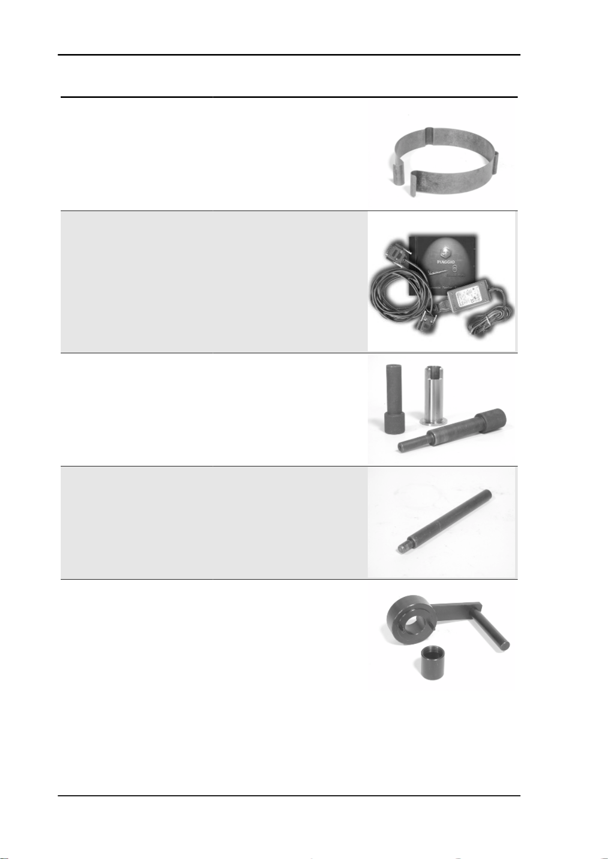
020472Y Flywheel lock wrench
Page 27
X8 400 Euro 3 Tooling
Stores code Description
020474Y Driving pulley lock wrench
020475Y Piston position checking tool
020476Y Stud bolt set
020478Y Punch for driven pulley roller casing
020479Y Countershaft lock wrench
020480Y Petrol pressure check set
TOOL - 27
Page 28
Tooling X8 400 Euro 3
Stores code Description
020481Y Control unit interface wiring
020482Y Engine support
020483Y 30 mm guide
020512Y Piston fitting fork
020527Y Engine support base
020604Y011 Fitting adapter
020565Y Flywheel lock calliper spanner
TOOL - 28
Page 29
X8 400 Euro 3 Tooling
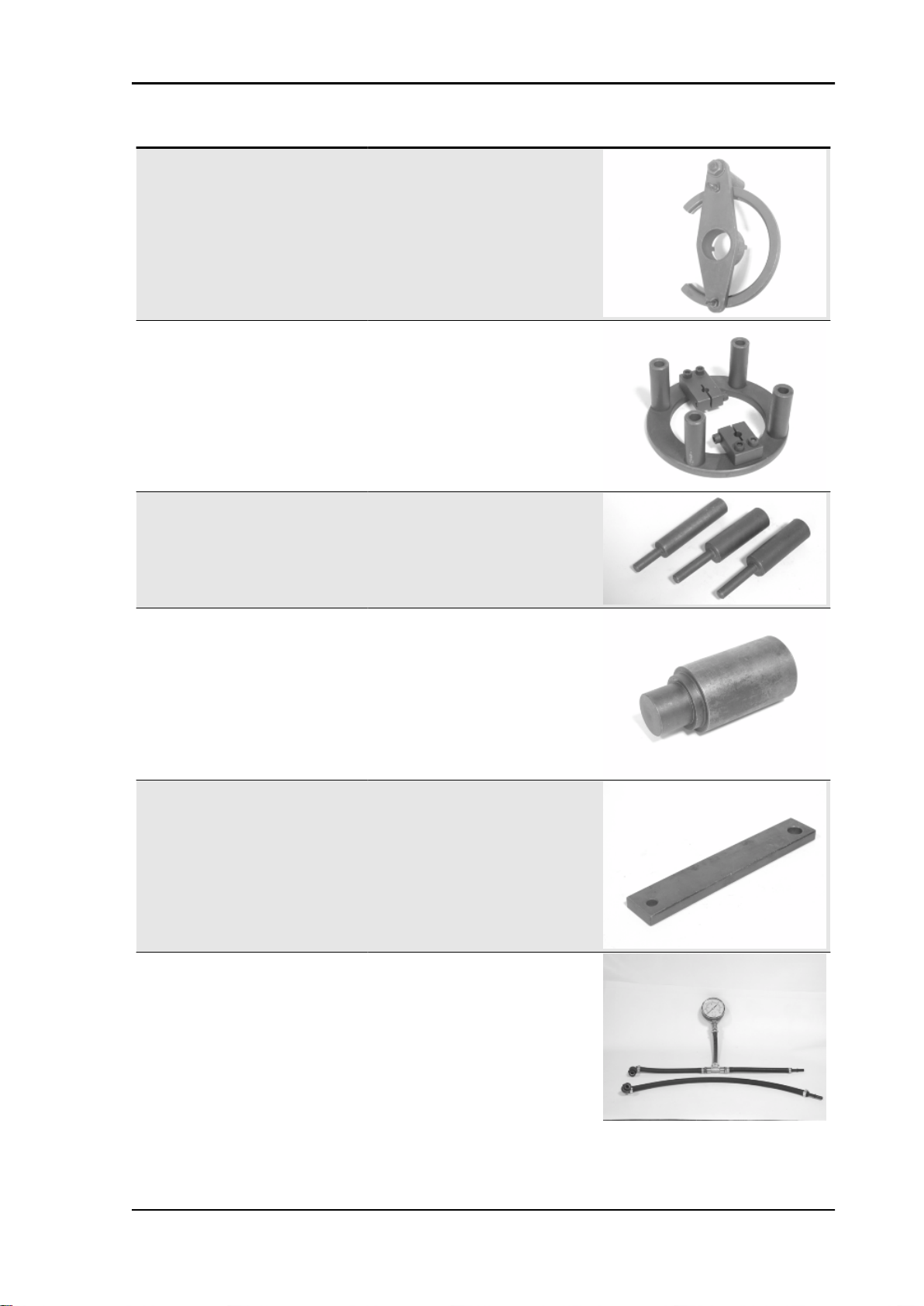
Stores code Description
Marelli MIU diagnosis software Marelli MIU diagnosis software
020640y software euro 3
TOOL - 29
Page 30

INDEX OF TOPICS
MAINTENANCE MAIN
Page 31

X8 400 Euro 3 Maintenance
Maintenance chart
EVERY 2 YEARS
60'
Action
Coolant - change
Brake fluid - change
AFTER 1,000 KM
Action
Safety locks - check
Throttle lever - adjustment
Engine oil - change
Electrical system and battery - check
Coolant level - check
Brake fluid level - check
Engine oil - replacement
Brake pads - check condition and wear
Tyre pressure and wear - check
Vehicle and brake test - road test
Hub oil - change
Crankcase breather - empty
Steering - adjustment
Injection system pipework - visual check
AFTER 10,000 KM AFTER 30,000 KM AFTER 50,000 KM AND AFTER 70,000 KM
Action
Safety locks - check
Spark plug - replacement
Driving belt - replacement
Throttle lever - adjustment
Air filter - check
Air filter belt compartment - check
Engine oil - change
Electrical system and battery - check
Coolant level - check
Brake fluid level - check
Engine oil - replacement
Brake pads - check condition and wear
Sliding block / variable speed rollers - change
Tyre pressure and wear - check
Vehicle and brake test - road test
Hub oil - check
Idle speed (*) - adjustment
Centre/side stand joint - lubrication
Suspensions - check
Steering - Check
Injection system pipework - visual check
MAIN - 31
Page 32

Maintenance X8 400 Euro 3
Action
Crankcase breather - empty
AFTER 20,000 KM AFTER 40,000 KM AFTER 60,000 KM AND AFTER 80,000 KM
Action
Safety locks - check
Bushing of driven pulley
Spark plug - replacement
Driving belt - replacement
Throttle lever - adjustment
Air filter - check
Air filter belt compartment - check
Engine oil - change
Valve clearance - check
Electrical system and battery - check
Coolant level - check
Brake fluid level - check
Engine oil - replacement
Brake pads - check condition and wear
Sliding block / variable speed rollers - change
Tyre pressure and wear - check
Vehicle and brake test - road test
Hub oil - check
Idle speed (*) - adjustment
Centre/side stand joint - lubrication
Crankcase breather - empty
Suspensions - check
Steering - Check
Injection system pipework - visual check
Fuel filter - check
(*) See instructions in «Idle speed adjustment» section
Spark plug
Proceed as follows:
1. Remove the lid to access the spark plug and
reach it with your hand;
2. Disconnect spark plug HV wire cap «A» ;
3. Unscrew the spark plug using the spark plug
wrench supplied;
4. When refitting, place the spark plug into the hole
at the required angle and tighten by hand until it is
finger tight;
5. Use the wrench only for final tightening of the
spark plug;
6. Place hood "A" fully over the spark plug.
N.B.
USING SPARK PLUGS OTHER THAN THE INDICATED
TYPE OR SHIELDLESS SPARK PLUG CAPS CAN CAUSE
ELECTRICAL SYSTEM FAILURES.
THE SPARK PLUG MUST BE REMOVED WHEN THE ENGINE IS COLD. SPARK PLUG REPLACEMENT OPERA-
MAIN - 32
Page 33

X8 400 Euro 3 Maintenance
TIONS ARE DESCRIBED IN THE SCHEDULED MAINTENANCE TABLE
THE USE OF ELECTRONIC CONTROL UNITS OR NONCOMPLIANT ELECTRONIC IGNITION SYSTEMS AND/OR
SPARK PLUGS OTHER THAN THOSE PRESCRIBED MAY
SERIOUSLY DAMAGE THE ENGINE.
IF THE SPARK PLUG NEEDS TO BE REMOVED AFTER A
FLOODED ENGINE SITUATION, IT IS ADVISABLE TO
KEEP THE TUBE CONNECTED TO THE SPARK PLUG,
AND THIS IN TURN TO A GROUND POINT AWAY FROM
THE SPARK PLUG HOLE TO AVOID OUTGOING PETROL
FROM CATCHING FIRE.
Characteristic
Spark plug
•
NGK CR7EKB
•
Champion RG6YC
Electrode gap
0.7-0.8 mm
Locking torques (N*m)
spark plug 12 to 14 Nm
Hub oil
Check
Check the oil in the rear hub.
Characteristic
Rear hub oil
Capacity approximately 250 cc
To check the rear hub oil level, proceed as follows:
- Park the scooter on flat ground resting on its centre stand.
- Set the strut that adjusts the level to its minimum height.
- Unscrew the oil dipstick, dry it with a clean cloth and reinsert it, screwing it in thoroughly.
MAIN - 33
Page 34

Maintenance X8 400 Euro 3
- Pull out the dipstick and check that the oil level is
between the MAX and MIN notches indicated on
the dipstick; if the level is below the MIN value, restore the proper amount of oil in the hub.
-Retighten the oil dipstick again and make sure it
is locked properly into place.
Replacement
- Prepare a suitable container.
- Remove the oil filler plug shown in the figure.
- Unscrew the oil drainage plug and drain out all
the oil.
- Tighten the drainage plug with its gasket and refill.
- Tighten the oil filler plug.
Characteristic
Rear hub oil
Capacity approximately 250 cc
Recommended oil:
TUTELA ZC 90
MAIN - 34
Page 35

X8 400 Euro 3 Maintenance
Air filter
Proceed as follows:
1. Unscrew the 9 fixing screws «A»;
2. Remove the air filter«B»
CAUTION
IF THE VEHICLE IS USED ON DUSTY ROADS, IT IS NECESSARY TO SERVICE THE AIR FILTER MORE OFTEN TO
AVOID DAMAGING THE ENGINE.
1. Wash the sponge with water and mild soap.
2. Dry it with a clean cloth and short blasts of compressed air.
3. Impregnate the sponge with a mixture of 50% petrol and 50% specified oil.
4. Gently squeeze the filtering element, let it drip dry and then refit it.
CAUTION
IF THE VEHICLE IS USED ON DUSTY ROADS, IT IS NECESSARY TO SERVICE THE AIR FILTER
MORE OFTEN TO AVOID DAMAGING THE ENGINE.
Recommended products
AGIP FILTER OIL Oil for air filter sponge
Mineral oil with specific additives for increased adhesiveness
Engine oil
In 4T engines, the engine oil is used to lubricate the distribution elements, the bench bearings and the
thermal group. An insufficient quantity of oil can cause serious damage to the engine.
In all 4T engines, the deterioration of the oil characteristics, or a certain consumption should be considered normal, especially if during the run-in period. Consumption levels in particular can be influenced
by the conditions of use (e.g.: oil consumption increases when driving at "full throttle".
MAIN - 35
Page 36

Maintenance X8 400 Euro 3
Check
This operation must be carried out with the engine cold and following the procedure below:
1) Rest the vehicle on the central stand and on a
flat ground.
2) Unscrew the cap/dipstick "A", dry it with a clean
cloth and reinsert it, screwing it thoroughly.
3) Remove the cap/dipstick again and check that
the level is between the max. and min levels; topup, if required.
Topping up from the MIN to MAX. level requires
around 1700 cc.
If the check is carried out after the vehicle has
been used, and therefore with a hot engine, the
level line will be lower; in order to carry out a correct check it is necessary to wait at least 10 minutes after the engine has been stopped, so as to
get the correct level.
Oil top up
The oil should be topped up after having checked the level and in any case by adding oil without ever
exceeding the MAX. level.
The restoration level between the MIN and MAX levels implies a quantity of oil of approx. 400 cc.
Engine oil filter
CAUTION
DO NOT DISPOSE OF OIL IN THE ENVIRONMENT. OIL, GASKET AND FILTER SHOULD BE DISPOSED OF ACCORDING TO THE REGULATIONS IN FORCE.
WARNING
AVOID TOUCHING PARTS OF THE ENGINE WHEN HOT, AS THIS MAY CAUSE BURNS.
- Remove the muffler.
- Remove the filler plug.
MAIN - 36
Page 37

X8 400 Euro 3 Maintenance
- Remove and clean the mesh pre-filter of the drain
cap with compressed air.
- Use a belt spanner for filters to remove cartridge
filter "C".
- Make sure the pre-filter and drain cap O-rings are
in good condition.
- Lubricate them and refit the mesh filter and oil
drain cap by tightening to the prescribed torque.
- Refit a new cartridge filter making sure to lubricate the O-ring before fitting, then screw until it
comes into contact with the seal and further tighten
to the prescribed torque.
- Refit the muffler.
- Add recommended engine oil.
- Start the engine and let it run for a few minutes and then turn it off.
After 5 minutes check the level and top up, if necessary, never exceed the MAX. level.
N.B.
IF THE OIL IS CHANGED WITHOUT CHANGING THE CARTRIDGE FILTER (1ST COUPON) ADD
AROUND 1500 CC OF OIL INSTEAD OF 1700 CC SINCE PART OF THE LUBRICATION CIRCUIT
IS FILLED.
Characteristic
Engine oil:
1700 cm³
Locking torques (N*m)
Engine oil drainage plug 24 ÷ 30 Engine oil filter 12 - 16
MAIN - 37
Page 38

Maintenance X8 400 Euro 3
Oil pressure warning light
Warning light (low oil pressure)
The vehicle is equipped with a warning light on the
instrument panel that lights up when the key is
turned to the «ON» position. However, this light
should switch off once the engine has been started.
If the light comes on during braking, at idling
speed or while turning, it is necessary to first
switch off the engine and then to check the oil
level and the lubrication system
Checking the valve clearance
- To check the clearance in the valves collimate
the references between the cam shaft control pulley and head.
- Use a feeler to make sure the clearance between
the valve and register screw correspond to the indicated values. If the clearance does not correspond, adjust it by loosening the lock nut using a
screwdriver on the set screw as shown in the figure.
Characteristic
Valve clearance: intake
0.15 mm (when cold)
Valve clearance: discharge
0.15 mm (when cold)
Cooling system
If noise or loss of liquid at the drain bore of the water pump is discovered, it will be necessary to overhaul
the pump as described in chapter "Flywheel cover".
Proceed to carry out a few preliminary operations as described below:
- Place the scooter on its centre stand and on flat ground.
- Remove the right footrest as described in the «Bodywork» Chapter.
- Remove the muffler to access the flywheel cover, as described in the «Engine» Chapter.
- Empty the cooling system by removing the couplings on the pump cover and the filler plug on the
expansion tank.
MAIN - 38
Page 39

X8 400 Euro 3 Maintenance
CAUTION
THIS OPERATION MUST BE CARRIED OUT WHEN THE ENGINE IS COLD.
- Remove the water pump cover as indicated in the
figure by loosening the 6 retaining screws.
- Proceeding as described in chapter "Engine",
partially drain the system and overhaul the pump.
- Refill and drain the system again once after having repaired the damaged and reinstalled all the
components.
N.B.
FOR CHANGING THE COOLANT AND BLEEDING THE
SYSTEM, SEE CHAPTER "COOLING SYSTEM".
Characteristic
Cooling system
approx. 1.8 litres
Level check
Adding engine coolant.
The fluid level must checked every 10,000 kilometres with a cold engine, in the way shown below:
Place the scooter on its centre stand and on flat
ground.
- Undo the screw shown in the figure and remove
the expansion tank cap on RHS.
- Top up if the fluid level is near or below the MIN
level edge. The liquid level must always be between the MIN and MAX level.
-The coolant consists of an ethylene glycol and
corrosion inhibitor based 50% de-ionised waterantifreeze solution mix.
CAUTION
DO NOT EXCEED THE MAX LEVEL WHEN FILLING SO
THAT COOLANT DOES NOT SPILL OVER THE EXPANSION TANK WHEN THE VEHICLE IS BEING USED.
Braking system
MAIN - 39
Page 40

Maintenance X8 400 Euro 3
Level check
The front and rear brake fluid reservoirs are both
positioned on the handlebars. Proceed as follows:
- Rest the vehicle on its centre stand with the handlebars perfectly horizontal;
- Check the fluid level through the sight glass
«C». A certain lowering of the level is caused by
wear on the pads.
Top-up
Proceed as follows: Loosen the screw "B" and lift
the plastic cover "A" in order to access the brake
fluid reservoir. Loosen the two fixing screws and
remove the reservoir cover; top-up with the recommended fluid without exceeding the 'MAX.'
mark.
This procedure applies to the rear brake pump topup operation; follow the same procedure for the
front brake pump.
Under normal climatic conditions, the fluid must be
changed every 20,000 km or anyway every two
years.
WARNING
ONLY USE DOT 4-CLASSIFIED BRAKE FLUID. BRAKE
CIRCUIT FLUID IS VERY CORROSIVE; MAKE SURE THAT
IT DOES NOT COME INTO CONTACT WITH THE PAINTWORK.
CAUTION
AVOID CONTACT OF THE BRAKE FLUID WITH YOUR
EYES, SKIN, AND CLOTHING. IN CASE OF ACCIDENTAL
CONTACT, WASH WITH WATER.
MAIN - 40
Page 41

X8 400 Euro 3 Maintenance
Headlight adjustment
Proceed as follows:
1. Position the unloaded vehicle, in running order
and with the tyres inflated to the prescribed pressure, on a flat surface 10 m away from a half-lit
white screen; ensure that the longitudinal axis of
the vehicle is perpendicular to the screen;
2. Turn on the headlight and check that the borderline of the projected light beam is lower than
9/10 and higher than 7/10 of the distance from the
ground to the centre of the vehicle headlight;
3. If not, adjust the headlight by turning the central
screw «A» placed behind the Piaggio badge.
N.B.
THE ABOVE PROCEDURE COMPLIES WITH THE EURO-
PEAN STANDARDS REGARDING MAXIMUM AND MINIMUM HEIGHT OF LIGHT BEAMS. REFER TO THE STATUTORY REGULATIONS IN FORCE IN EVERY COUNTRY
WHERE THE VEHICLE IS USED.
Checking the end compression pressure
- Remove the spark plug hood with cold engine.
- Remove the ignition spark plug.
- Fit a compression test gauge into the spark plug seat using a 10 mm spark plug coupling, at the proper
locking torque.
- Set ignition switch to «ON», wait a few seconds and then disconnect the revolution timing sensor
connector in order to deactivate the injector and the spark plug.
- Let the engine run using the starter motor and with the throttle body in fully open position until the
gauge value is steady.
- If the pressure is higher than the indicated, remove the tool and proceed to refit to the vehicle.
- If the pressure is lower than indicated, check the rpm at which the test is carried out; if lower than 450
g/1', check the start-up system.
MAIN - 41
Page 42

Maintenance X8 400 Euro 3
If the end of compression pressure is lower than the standard, remove the test gauge connector and
add some cc of oil to the combustion chamber, make the engine turn (preferably manually) to lubricate
the cylinder.
Repeat the pressure test:
if the new values are low again, check the condition of the valve gaskets.
Pressure values too high in a new engine signal poor sealing of the rings.
Characteristic
Compression ratio
10.6 ± 0.5 : 1
Locking torques (N*m)
Spark plug 12 ÷ 14
MAIN - 42
Page 43

INDEX OF TOPICS
ELECTRICAL SYSTEM ELE SYS
Page 44

Electrical system X8 400 Euro 3
KEY:
1. Magneto flywheel
2. Voltage regulator
3. Revolution sensor
4. Throttle valve position sensor
5. Ambient temperature sensor
6. Stepper motor for idle jet
7. Electric fan
8. Engine temperature sensor
9. Remote control for electric fan
10. Key switch
11. Injection load remote control
12. Fuse holder B
13. Fuse holder A
14. 12V - 180W socket
15. Engine stop remote control
16. Engine stop switch
17. Diode
18. Battery
19. Starter motor
ELE SYS - 44
Page 45

X8 400 Euro 3 Electrical system
20. Start up remote control switch
21. Starter button
22. Wiring for radio display
23. Wiring for radio
24. Stop button on rear brake
25. Stop button on front brake
26. Boot switch
27. Boot actuator
28. Saddle opening switch
29. Saddle opening actuator
30. Horn button
31. Horn
32. Wiring for saddle opening control unit
33. Helmet compartment light switches
34. Helmet compartment light bulb
35. Wiring for antitheft device
36. Left rear turn indicator bulbs
37. Rear headlight assembly
A. Tail light Bulb
B. Stop light Bulb
38. License plate bulb
39. Right rear turn indicator bulbs
40. Left front turn indicator bulbs
41. Front headlight assembly
A. Low-beam bulb
B.A. Parking light
C. High-beam headlight bulb
42. Right front turn indicator bulbs
43. Light switch
44. Turn indicator switch
45. Turn indicator remote control
46. Remote control headlight
47. Fuel level transmitter
48. Clock reset button
49. Instrument panel
50. Oil pressure sensor
51. Immobilizer aerial
52. Immobilizer decoder
ELE SYS - 45
Page 46

Electrical system X8 400 Euro 3
53. Fuel pump
54. Fuel injector
55. Spark plug
56. High voltage coil
57. Lambda probe
58. Diagnostics socket
59. Injection ECU
60. Stand switch
Ar = Orange, Az = Sky Blue, Bi = White, Bl = Blue, Gi = Yellow, Gr = Grey, Ma = Brown, Ne = Black,
Ro = Pink, Rs = Red, Ve = Green, Vi = Purple
Electrical system layout - Version without switch on stand
WARNING
WE INFORM THAT THE FIRST 1000 VEHICLES ARE NOT EQUIPPED WITH THE SWITCH ON THE
SIDE STAND AND THE RELEVANT WIRING. THE LAYOUT INDICATED HERE IS THE REFERENCE FOR THESE VEHICLES.
KEY:
1. Magneto flywheel
2. Voltage regulator
3. Revolution sensor
4. Throttle valve position sensor
ELE SYS - 46
Page 47

X8 400 Euro 3 Electrical system
5. Ambient temperature sensor
6. Stepper motor for idle jet
7. Electric fan
8. Engine temperature sensor
9. Remote control for electric fan
10. Key switch
11. Injection load remote control
12. Fuse holder B
13. Fuse holder A
14. 12V - 180W socket
15. Engine stop remote control
16. Engine stop switch
17. Diode
18. Battery
19. Starter motor
20. Start up remote control switch
21. Starter button
22. Wiring for radio display
23. Wiring for radio
24. Stop button on rear brake
25. Stop button on front brake
26. Boot switch
27. Boot actuator
28. Saddle opening switch
29. Saddle opening actuator
30. Horn button
31. Horn
32. Wiring for saddle opening control unit
33. Helmet compartment light switches
34. Helmet compartment light bulb
35. Wiring for antitheft device
36. Left rear turn indicator bulbs
37. Rear headlight assembly
A. Tail light Bulb
B. Stop light Bulb
38. License plate bulb
39. Right rear turn indicator bulbs
40. Left front turn indicator bulbs
ELE SYS - 47
Page 48

Electrical system X8 400 Euro 3
41. Front headlight assembly
A. Low-beam bulb
B.A. Parking light
C. High-beam headlight bulb
42. Right front turn indicator bulbs
43. Light switch
44. Turn indicator switch
45. Turn indicator remote control
46. Remote control headlight
47. Fuel level transmitter
48. Clock reset button
49. Instrument panel
50. Oil pressure sensor
51. Immobilizer aerial
52. Immobilizer decoder
53. Fuel pump
54. Fuel injector
55. Spark plug
56. High voltage coil
57. Lambda probe
58. Diagnostics socket
59. Injection ECU
Components arrangement
Diagnostic socket
In order to access the diagnostic socket remove
the battery cover.
ELE SYS - 48
Page 49

X8 400 Euro 3 Electrical system
H.V. coil
In order to access the HV coil remove the chassis
central cover; to remove it, loosen the screws inside the battery compartment.
Saddle opening remote control unit.
In order to access the saddle opening control unit,
remove the left side fairing.
Electronic control unit ECU
In order to access the control unit remove the front
top fairing and the shield back plate.
ELE SYS - 49
Page 50

Electrical system X8 400 Euro 3
Immobilizer decoder
In order to access the immobilizer decoder remove
the front top fairing and the shield back plate.
Relays and diode group
In order to access the relays and the diode unit
remove the front top fairing and the shield back
plate.
Voltage regulator
In order to access the voltage regulator, remove
the right side fairing cover.
Lambda probe
The lambda probe is mounted on the exhaust
manifold
Conceptual diagrams
ELE SYS - 50
Page 51

X8 400 Euro 3 Electrical system
Ignition
KEY:
3. Revolution sensor
10. Key switch
11. Injection load remote control
12. Fuse holder B
13. Fuse holder A
15. Engine stop remote control
16. Engine stop switch
17. Diode
18. Battery
49. Instrument panel
51. Immobilizer aerial
52. Immobilizer decoder
55. Spark plug
56. High voltage coil
59. Injection ECU
60. Stand switch
ELE SYS - 51
Page 52

Electrical system X8 400 Euro 3
Headlights and automatic starter section
KEY:
10. Key switch
12. Fuse holder B
13. Fuse holder A
15. Engine stop remote control
16. Engine stop switch
17. Diode
18. Battery
35. Wiring for antitheft device
36. Left rear turn indicator bulbs
37. Rear headlight assembly
A. Tail light Bulb
B. Stop light Bulb
38. License plate bulb
39. Right rear turn indicator bulbs
40. Left front turn indicator bulbs
41. Front headlight assembly
A. Low-beam bulb
ELE SYS - 52
Page 53

X8 400 Euro 3 Electrical system
B. Parking light
C. High-beam headlight bulb
42. Right front turn indicator bulbs
43. Light switch
44. Turn indicator switch
45. Turn indicator remote control
46. Remote control headlight
49. Instrument panel
60. Stand switch
Battery recharge and starting
KEY:
1. Magneto flywheel
2. Voltage regulator
10. Key switch
12. Fuse holder B
13. Fuse holder A
16. Engine stop switch
17. Diode
18. Battery
ELE SYS - 53
Page 54

Electrical system X8 400 Euro 3
19. Starter motor
20. Start up remote control switch
21. Starter button
24. Stop button on rear brake
25. Stop button on front brake
37. Rear headlight assembly
A. Tail light Bulb
B. Stop light Bulb
60. Stand switch
Level indicators and enable signals section
KEY:
3. Revolution sensor
4. Throttle valve position sensor
5. Ambient temperature sensor
6. Stepper motor for idle jet
8. Engine temperature sensor
10. Key switch
11. Injection load remote control
12. Fuse holder B
ELE SYS - 54
Page 55

X8 400 Euro 3 Electrical system
13. Fuse holder A
15 Engine stop remote control
16. Engine stop switch
17. Diode
18. Battery
47. Fuel level transmitter
49. Instrument panel
50. Oil pressure sensor
53. Fuel pump
54. Fuel injector
57. Lambda probe
59. Injection ECU
60. Stand switch
Devices and accessories
KEY:
7. Electric fan
8. Engine temperature sensor
9. Remote control for electric fan
10. Key switch
ELE SYS - 55
Page 56

Electrical system X8 400 Euro 3
12. Fuse holder B
13. Fuse holder A
14. 12V - 180W socket
15. Engine stop remote control
16. Engine stop switch
17. Diode
18. Battery
26. Boot switch
27. Boot actuator
28. Saddle opening switch
29. Saddle opening actuator
30. Horn button
31. Horn
32. Wiring for saddle opening control unit
33. Helmet compartment light switches
34. Helmet compartment light bulb
35. Wiring for antitheft device
59. Injection ECU
60. Stand switch
Checks and inspections
Immobiliser
The electronic ignition system is controlled by the control unit with the integrated Immobilizer system.
The immobilizer is an anti-theft system that allows the vehicle to be operated only when it is started with
coded keys recognised by the control unit. The code is integrated in a transponder in the key block.
This allows the driver clear operation without having to do anything other than just turning the key. The
Immobiliser system consists of the following components:
- electronic control unit
- decoder
- immobilizer aerial
- master key with integrated transponder (brown key)
- service key with incorporated transponder (black key)
- HV coil
- diagnosis LED
The diagnosis LED also works as a theft-deterrent blinker. This function is activated every time the
ignition switch is turned to the "OFF" position, or the emergency stop switch is turned to the "OFF"
position. It remains activated for 48 hours in order not to affect the battery charge. When the ignition
ELE SYS - 56
Page 57

X8 400 Euro 3 Electrical system
switch is turned to the "ON" position, the theft-deterrent blinker function is deactivated. Subsequently,
a flash confirms the switching to the "ON" status. The duration of the flash depends on the programming
of the electronic control unit If the LED is off regardless of the position of the ignition-key switch and/or
the instrument panel is not initiated, check if:
•
there is battery voltage
•
efficiency of fuse No. 7
•
there is power to the control unit as specified below:
Disconnect the connector from the control unit. Check the following conditions:
With the key switch set to OFF:
•
Battery voltage between terminals 17-23 and terminals 17-chassis ground (continuous power supply). If there is no voltage, check that fuse No. 6 is in good conditions.
With the key switch in position ON and the engine stop switch in RUN:
•
Battery voltage between terminals 26-23 and terminals 26-chassis ground (continuous power supply). If there is no voltage, check:
1. that fuses No. 11 and No. 2 and their wirings are in good conditions.
2. that the engine stop remote control switch is in good conditions.
•
Check for voltage on the white-black cable at the exit from the engine stop remote control
switch. If there is no voltage, check:
1. key switch contacts
2. the condition of the engine stop switch, then the ground connection of the green/black cable of the
engine stop remote control switch with the stand lifted and the engine stop switch in the RUN position.
3. that the engine stop remote control switch diode is in good conditions.
If no fault is found, replace the control unit.
N.B.
AN ACCIDENTAL LOSS OF THE SERVICE KEY PROGRAMMING CAN ARISE FROM GENERAL
FAULTS OF THE IGNITION SYSTEM. IN THIS CASE, CHECK THE HV LINE SHIELDING.
In any case it is advisable to use resistive spark plugs.
ELE SYS - 57
Page 58

Electrical system X8 400 Euro 3
Virgin circuit
When the ignition system is not encrypted, any key
will start the engine but limited to 2000 rpm. The
keys can only be recognised when the decoder
has been correctly programmed. The procedure
for programming a new decoder requires the recognition of the "master" key as the first key to be
programmed: this is particularly important as it is
the only key that allows the decoder to be reset
and reprogrammed for programming the service
keys.
The master and service keys must be used to code
the system as follows:
- Insert the Master key, turn it to «ON» and keep
this position for two seconds (lower and upper limits 1 to 3 seconds).
- Insert the service key and turn it to «ON» for 2
seconds.
- If you have copies of the key, repeat the operation
with each key.
- Insert the MASTER key again and turn it to «ON»
for 2 seconds.
The maximum time to change keys is 10 seconds.
A maximum of 7 service keys can be programmed
at one time.
It is essential to adhere to the times and the procedure. If you do not, start again from the beginning. Once the system has been programmed,
master key transponder, decoder and control unit
are strictly matched. With this link established, it is
now possible to encode new service keys, in the
event of losses, replacements, etc. Each new programming deletes the previous one so, in order to
add or eliminate keys, you must repeat the procedure using all the keys you intend to keep using.
If a service key becomes uncoded, the efficiency
of the high voltage circuit shielding must be thor-
ELE SYS - 58
Page 59

X8 400 Euro 3 Electrical system
oughly inspected: In any case it is advisable to use
resistive spark plugs.
Characteristic
MASTER key:
BROWN KEY
SERVICE key.
BLACK KEY
Diagnostic codes
The immobiliser system is tested each time the ignition-key switch is turned from OFF to ON. During
this diagnosis phase a number of control unit statuses can be seen and various light codes displayed. Regardless of the code transmitted, if at
the end of the diagnosis the led remains off permanently, the ignition is enabled. If, however, the
led remains on permanently, it means the ignition
is inhibited:
1. New decoder - key inserted: a single 2 second
flash is displayed, after which the LED remains off
permanently. The keys can be stored to memory,
the vehicle can be started but with a limitation imposed on the number of revs.
2. New decoder - transponder missing or illegible: The LED is permanently ON; in this condition,
no operations are possible, including starting of
the vehicle.
3. Decoder programmed - service key inserted
(normal operating condition): a single 0.7-sec-
ond flash is displayed, after which the LED remains off steadily. The engine can be started.
4. Decoder programmed - master key inserted: a 0.7-sec flash is displayed followed by the
LED remaining off for 2 sec. and then by short
0.46-sec flashes the same number of times as
there are keys stored in the memory including the
Master key. When the diagnosis has been com-
ELE SYS - 59
Page 60

Electrical system X8 400 Euro 3
pleted, the LED remains permanently OFF. The
engine can be started.
5. Decoder programmed - fault detected: a light code is displayed according to the fault detected,
after which the LED remains on steadily. The engine cannot be started. The codes that can be transmitted are:
•
1-flash code
•
2-flash code
•
3-flash code
Diagnostic code - 1 flash
A one-flash code indicates a system where the serial line is not present or is not detected. Check the
Immobilizer aerial wiring and change it if necessary.
Diagnostic code - 2 flashes
A 2-flash code indicates a system where the decoder does not recognise the transponder signal.
This might depend on the inefficiency of the immobiliser aerial or the transponder.
Turn the switch to ON using several keys: if the
code is repeated even with the Master key, check
the aerial wiring and change it if necessary. Otherwise replace the faulty key and/or reprogram the
decoder. If the problem persists, replace the decoder.
ELE SYS - 60
Page 61

X8 400 Euro 3 Electrical system
Diagnostic code - 3 flashes
The 3-flash code indicates a system where the decoder does not recognise the key. Turn the switch
to ON using several keys: If the error code is repeated even with the Master key, replace the decoder. If this is not the case, reprogram the
decoder.
Battery recharge circuit
The recharge system is provided with a three phase alternator with permanent flywheel.
The alternator is directly connected to the voltage regulator.
This, in its turn, is connected directly to the ground and the battery positive terminal passing through
the 30A protective fuse.
This system therefore requires no connection to the key switch.
The three- phase generator provides good recharge power and at low revs, a good compromise is
achieved between generated power and idle stability.
Stator check
Checking the stator windings
WARNING
THIS CHECK-UP CAN BE MADE WITH THE STATOR PROPERLY INSTALLED.
1) Remove the right side panel.
2) Disconnect the connectors between stator and regulator with the three yellow cables.
3) Measure the resistance between each of the yellow terminals and the other two.
Electric characteristic
Resistance:
0.2 - 1 Ω
ELE SYS - 61
Page 62

Electrical system X8 400 Euro 3
4) Check that there is insulation between the each
yellow cable and the ground.
5) If values are incorrect, replace the stator.
Recharge system voltage check
Maximum current output check.
- With engine off and panel set to "ON" turn on the lights and let the battery voltage set to 12V.
- Connect ammeter pliers to the 2 recharge positive poles in output from the regulator.
- Keep the lights on and start the engine, bring it to normal speed and read the values on the ammeter.
With an efficient battery a value must be detected: > 20A
VOLTAGE REGULATOR/RECTIFIER
Specification
Type Non-adjustable three-phase transistor
Voltage 14 ÷ 15V at 5000 rpm with lights off
Look for any leakage
1) Check that the battery does not show signs of leaking fluid before checking the output voltage.
2) Turn the ignition key to OFF and connect the multimeter leads between the battery negative pole (-)
and the Black cable.
3) With the multimeter leads connected, disconnect the Black cable from the battery negative pole (-).
4) With the ignition key always at OFF, the reading indicated by the ammeter must be ≤ 0.5 mA.
Charging current check
WARNING
BEFORE CARRYING OUT THE CHECK, MAKE SURE THAT THE BATTERY IS IN GOOD WORKING ORDER.
Desc./Quantity
1) Place the vehicle on its centre stand
2) With the battery correctly connected to the circuit, place the tester terminals between the battery
terminals..
3) Start the engine, ensure that the lights are all out, increase the engine speed and at the same time
measure the voltage.
Electric characteristic
Voltage ranging between 14.0 and 15.0V at 5000 rpm.
ELE SYS - 62
Page 63

X8 400 Euro 3 Electrical system
Turn signals system check
The turn indicator circuit is controlled by the electronic control unit. In the case it does not work, it is
necessary to:
1. Check that fuse 8 is in working order
2. Check the function of the bulbs
3. Check the function of the turn signal indicator switch
4. Check that the turn indicator remote control is in working order
5. With the key switch set to ON, switch the stop engine to RUN without removing the turn indicator
remote control; check that there is voltage to the battery on the turn indicator switch connector. Next,
check for voltage on the blue-black cable of the remote control, on the control unit side.
If there is no voltage, check the wiring and the correct function of the electrical control units. Replace
the control unit if the failure continues.
Lights list
LIGHT BULBS TABLE
Specification
1 High-beam light bulb Type: HALOGEN (H7)
2 Low-beam bulb Type: HALOGEN (H1)
3 Front tail light bulb Type: ALL GLASS
4 Instrument panel bulb Type: ALL GLASS
5 Clock light bulb Type: ALL GLASS
6 Front turn indicator bulb Type: ALL GLASS
7 Helmet compartment light bulb Type: CYLINDRIC
8 Rear turn indicator light bulb Type: ALL GLASS
9 Rear tail light bulb Type: ALL GLASS
10 Stop light bulb Type: SPHERICAL
11 License plate light bulb Type: ALL GLASS
12 12V - 1.2W warning light bulb Type: ALL GLASS
Application: Lighting system warning light - Full beam
headlamp warning light - Open boot warning light - In-
Desc./Quantity
Power: 12V - 55W
Quantity: 1
Power: 12V - 55W
Quantity: 1
Power: 12V - 5W
Quantity: 2
Power: 12V - 1.2W
Quantity: 4
Power: 12V - 2W
Quantity: 1
Power: 12V - 5W
Quantity: 2 RHS + 2 LHS
Power: 12V - 5W
Quantity: 1
Power: 12V - 5W
Quantity: 2 RHS + 2 LHS
Power: 12V - 5W
Quantity: 2
Power: 12V - 10W
Quantity: 2
Power: 12V - 5W
Quantity: 1
jection warning light
ELE SYS - 63
Page 64

Electrical system X8 400 Euro 3
Specification Desc./Quantity
Quantity: 4
13 12V - 2W warning light bulbs Type: ALL GLASS
14 12V - 3W warning light bulbs Type: ALL GLASS
Application:Fuel reserve
Quantity: 1
Application: Turn indicators
Quantity: 2
Application:Engine oil pressure
Quantity: 1
Fuses
The electrical system is equipped with 12 protective fuses for the various circuits on the scooter,
subdivided into two fuse boxes located alongside
the battery.
The chart shows the position and characteristics
of the fuses in the vehicle.
CAUTION
NEVER TRY TO REPLACE A BLOWN FUSE WITH A FUSE
OF A DIFFERENT RATING THAN THAT SPECIFIED OR USING OTHER MATERIAL (FOR EXAMPLE, A PIECE OF
ELECTRICAL WIRE).
BESIDES, IF AFTER REPLACING A FUSE, THE NEW FUSE
ALSO BLOWS, THE SCOOTER NEEDS TO BE TAKEN TO
AN AUTHORISED PIAGGIO/GILERA SERVICE CENTRE TO
IDENTIFY THE CAUSE OF THE FAULT AND AVOID FURTHER DAMAGE TO THE ELECTRIC SYSTEM COMPONENTS OR THE VEHICLE ITSELF.
CAUTION
MODIFICATIONS OR REPAIRS TO THE ELECTRICAL SYSTEM, PERFORMED INCORRECTLY OR WITHOUT STRICT
ATTENTION TO THE TECHNICAL SPECIFICATIONS OF
THE SYSTEM, CAN CAUSE ERRORS IN FUNCTIONING
AND RISK OF FIRE.
FUSE TABLE
Specification
1 Fuse No. 1 Threshold of operation: 30 A
Location: Battery compartment on the left side
Protected circuits: Battery charge
2 Fuse No. 2 Threshold of operation: 15A
Location: Battery compartment on the left side
Protected circuits: Lines protected by fuses 8, 9, 10,12
3 Fuse No. 3 Threshold of operation: 15A
Location: Battery compartment on the left side
Protected circuits: 12V 180W socket - Wiring for anti-
theft device - Electrical fan remote control - Saddle opening control unit - Actuator for opening saddle and glove-
4 Fuse No. 4 Threshold of operation: 10 A
Desc./Quantity
- Engine stop remote control
box
ELE SYS - 64
Page 65

X8 400 Euro 3 Electrical system
Specification Desc./Quantity
Location: Battery compartment on the left side
Protected circuits: Remote control for injection com-
ponents (fuel pump, injector, h.v. coil.)
5 Fuse No. 5 Threshold of operation: 10 A
6 Fuse No. 6 Threshold of operation: 3 A
7 Fuse No. 7 Threshold of operation: 7.5A
8 Fuse No. 8 Threshold of operation: 7.5A
9 Fuse No. 9 Threshold of operation: 10 A
10 Fuse No. 10 Threshold of operation: 7.5A
11 Fuse No. 11 Threshold of operation: 7.5A
12 Fuse No. 12 Threshold of operation: 7.5A
Location: Battery compartment on the left side
Protected circuits: Headlight remote control - Bulb for
helmet compartment light - Warning light for saddle/rear
compartment cover open
Location: Battery compartment on the left side
Protected circuits: Ignition ECU - Immobilizer decoder
Location: Battery compartment on the right side
Protected circuits: Instrument panel - Wiring for radio
Location: Battery compartment on the right side
Protected circuits: Saddle opening control unit - Turn
indicator remote control
Location: Battery compartment on the right side
Protected circuits: Headlight remote control - Start-up
remote control - Stop light bulbs
Location: Battery compartment on the right side
Protected circuits: Horn - Taillight and license plate
light bulbs - Instrument panel
Location: Battery compartment on the right side
Protected circuits: Remote control for injection com-
ponents (fuel pump, injectors, h.v. coil.) - Electrical fan
remote control - Ignition ECU - Immobilizer decoder
Location: Battery compartment on the right side
Protected circuits: Wiring for radio - Wiring for anti-theft
device - Instrument panel
Remote controls - Diode unit
The electrical system is fitted with 5 remote control
switches plus the diode unit located under the front
shield, and a start-up switch located under the right
side fairing.
In order to access the remote control switches under the shield it is necessary to:
•
- Remove the front shield.
•
Remove the knee-guard panel.
To access the starter remote control it is necessary
to remove the right side fairing.
The following table shows the functions of each
remote control switch:
A: Diode unit (yellow)
B: Electric fan starter
C. Light remote control
D: Injection load remote control
ELE SYS - 65
Page 66

Electrical system X8 400 Euro 3
E: Engine stop remote control switch
F: Turn indicator remote control
G: Starter remote control
Dashboard
A = Twin scale speedometer (km/h and mph)
B = Fuel gauge
C = Antitheft device LED
D = Coolant temperature gauge
E = Right turn indicator warning light
E = Left turn indicator warning light
H = Low fuel warning light
I = Lights ON warning light
L = High-beam warning light
M = Low oil pressure warning light
N = Helmet compartment light ON warning light
O = Preset warning light
P = Analogue clock
Q = Total odometer
R = Trip odometer
S = Trip odometer reset button
The clock, powered directly by the vehicle's battery, may be set by pressing the «T» button located inside the LHS glove-box on the knee-guard
panel.
Pressing the button for less than one second will
add one minute to the displayed time; Keep the
«T» button pressed to rapidly increase the time.
Sealed battery
Commissioning sealed batteries
If the vehicle is provided with a sealed battery, the only maintenance required is the check of its charge
and recharging, if necessary.
These operations should be carried out before delivering the vehicle, and on a six-month basis while
the vehicle is stored in open circuit.
Besides, upon pre-delivery it is therefore necessary to check the battery charge and recharge it, if
required, before storing the vehicle and, afterwards, every six months.
ELE SYS - 66
Page 67

X8 400 Euro 3 Electrical system
INSTRUCTIONS FOR THE BATTERY REFRESH AFTER OPEN-CIRCUIT STORAGE
1) Voltage check
Before installing the battery on the vehicle, check the open circuit voltage with a regular tester.
- If voltage exceeds 12.60 V, the battery can be installed without any renewal recharge.
- If voltage is below 12.60 V, a renewal recharge is required as explained in 2).
2) Constant voltage battery charge mode
- Constant voltage charge equal to 14.40 ÷ 14.70V
-Initial charge voltage equal to 0.3 ÷ 0.5 for Nominal capacity
- Charge time:
10 to 12 h recommended
Minimum 6 h
Maximum 24 h
3) Constant current battery charge mode
-Charge current equal to 1/10 of the nominal capacity of the battery
- Charge time: 5 h
Specific tooling
020333Y Single battery charger
020334Y Multiple battery charger
Cleaning the battery
The battery should always be kept clean, especially on its top side, and the terminals should be coated
with Vaseline.
CAUTION
NEVER USE FUSES WITH A CAPACITY HIGHER THAN THE RECOMMENDED CAPACITY. USING
A FUSE OF UNSUITABLE RATING MAY SERIOUSLY DAMAGE THE VEHICLE OR EVEN CAUSE
A FIRE.
CAUTION
CHARGE THE BATTERY BEFORE USE TO ENSURE OPTIMUM PERFORMANCE. FAILURE TO
CHARGE THE BATTERY ADEQUATELY BEFORE BEING PUT INTO OPERATION WILL LEAD TO
A PREMATURE FAILURE OF THE BATTERY.
If the scooter is not used for a given time (1 month or more) it will be necessary to periodically recharge
the battery.
The battery runs down completely in the course of three months. If it is necessary to refit the battery in
the vehicle, be careful not to reverse the connections, remembering that the ground wire (black) marked
(-) must be connected to the negative clamp while the other two red wires marked (+) must be connected to the clamp marked with the + positive sign.
ELE SYS - 67
Page 68

Electrical system X8 400 Euro 3
Dry-charge battery
- Remove the short closed tube and the caps, then
pour sulphuric acid into the cells using the type
specified for batteries with a specific gravity of
1.26, corresponding to 30 Bé at a minimum temperature of 15°C until the upper level is reached.
- Allow to stand for at least 2 hours, then top up the
level with sulphuric acid.
- Within 24 hours, recharge using the special battery charger (single) or (multiple) at an intensity of
about 1/10 of the battery nominal capacity and until
the acid gravity is about 1.27, corresponding to 31
Bé and such values become steady.
- After charging, top up the acid (adding distilled
water). Close and clean carefully.
- After carrying out the operations above, install the
battery on the scooter, observing the connections
described in point 3) of paragraph "Battery re-
charge".
Specific tooling
020333Y Single battery charger
020334Y Multiple battery charger
1 Keep the pipe in vertical position
2 Inspect visually
3 The float must be freed
Checking the electrolyte level
The electrolyte level must be checked frequently and must reach the upper level. Only use distilled
water, to restore this level. If it is necessary to add water too frequently, check the vehicle's electrical
system: the battery works overcharged and is subject to quick wear.
Charging status check
After topping-up the electrolyte level, check its density using special density gauge.
When the battery is charged, you should detect a density of 30 to 32 Bé corresponding to a specific
weight of 1.26 to 1.28 at a temperature of no lower than 15° C.
A density reading of less than 20° Bé indicates that the battery is completely flat and it must therefore
be recharged.
If the scooter is not used for a given time (1 month or more) it will be necessary to periodically recharge
the battery.
ELE SYS - 68
Page 69

X8 400 Euro 3 Electrical system
The battery runs down completely in the course of three months. When refitting the battery onto the
scooter pay attention not to invert the cables, bearing in mind that the earth (black) wire marked with
a (-) must be connected to the negative terminal whilst the other two red wires, marked with a (+) must
be attached to the positive, + terminal.
Battery recharge
WARNING
BEFORE RECHARGING THE BATTERY, REMOVE THE PLUGS OF EACH CELL. KEEP SPARKS
AND NAKED FLAMES AWAY FROM THE BATTERY WHILE RECHARGING.
Remove the battery from the vehicle removing the negative clamp first.
Normal bench charging must be performed using the special battery charger (single) or (multiple), setting the battery charge selector to the type of battery that requires recharging (i.e., at a current equal
to 1/10 of the battery rated capacity). Connections to the power supply source must be implemented
by connecting corresponding poles (+ to + and - to - ).
Specific tooling
020333Y Single battery charger
020334Y Multiple battery charger
The battery should always be kept clean, especially on its top side, and the terminals should be coated
with Vaseline.
CAUTION
NEVER USE FUSES WITH A CAPACITY HIGHER THAN THE RECOMMENDED CAPACITY. USING
A FUSE OF UNSUITABLE RATING MAY SERIOUSLY DAMAGE THE VEHICLE OR EVEN CAUSE
A FIRE.
CAUTION
ORDINARY AND DRINKING WATER CONTAINS MINERAL SALTS THAT ARE HARMFUL FOR
THE BATTERY. FOR THIS REASON, YOU MUST ONLY USE DISTILLED WATER.
CAUTION
CHARGE THE BATTERY BEFORE USE TO ENSURE OPTIMUM PERFORMANCE. FAILURE TO
CHARGE THE BATTERY ADEQUATELY BEFORE BEING PUT INTO OPERATION WILL LEAD TO
A PREMATURE FAILURE OF THE BATTERY.
Battery installation
To access the battery, proceed as follows:
1. Place the scooter on its centre stand;
2. Open the saddle.
3. Remove the two screws A and the cover B.
4. Remove the electrical connections, disconnect
the breather pipe C and take out the battery.
To refit, follow the steps but in reverse order.
CAUTION
ELE SYS - 69
Page 70

Electrical system X8 400 Euro 3
IN ORDER TO AVOID DAMAGING THE ELECTRICAL SYSTEM, NEVER DISCONNECT THE WIRING WHILE THE ENGINE IS RUNNING. DO NOT TIP THE SCOOTER TOO MUCH
IN ORDER TO AVOID DANGEROUS LEAKAGE OF BATTERY ELECTROLYTE.
Connectors
ECU
Layout of the system-side connectors and the connectors on the electronic control unit.
ECU
Specification
1 Throttle potentiometer power supply +5 V
2 Oxygen sensor (-)
3 4 Engine temperature (+)
5 86 electric fan remote control switch
6 Stepper motor Stepper motor
7 Engine rpm sensor
8 Oxygen sensor (+)
9 EMS diagnostic connector
10 EMS diagnostic connector
11 Throttle potentiometer signal
12 Engine rpm sensor
Desc./Quantity
ELE SYS - 70
Page 71

X8 400 Euro 3 Electrical system
Specification Desc./Quantity
13 Injector control (negative)
14 Stepper motor Stepper motor
15 Injection telltale light (-)
16 Decoder (serial) Overturn sensor
17 Battery powered (+)
18 Air temperature sensor (+)
19 Fuel pump (-)
20 H.V. coil (negative control)
21 Stepper motor Stepper motor
22 Sensor power supply (-)
23 Control unit negative
24 Stepper motor Stepper motor
25 Turn indicator control device
26 Continuous power supply (positive)
Seat opening receiver
SADDLE OPENING RECEIVER CONTROL UNIT
Specification
1 Radio aerial
2 Actuator positive output 1
3 Reset / Input clearing
4 Battery positive
5 (Not connected)
6 Live positive lead
7 Ground lead
8 (Not connected)
9 Actuator positive output 2
10 Data for alarm output
11 (Not connected)
Immobiliser decoder
Desc./Quantity
Specification
1 -
IMMOBILIZER DECODER
Desc./Quantity
ELE SYS - 71
Page 72

Electrical system X8 400 Euro 3
Specification Desc./Quantity
2 Immobilizer LED control (negative)
3 Base power supply (positive)
4 Negative
5 6 Electronic control unit EMS (serial)
7 8 Continuous power supply (positive) Immobilizer aerial
Engine rev. sensor
REV SENSOR
Specification Desc./Quantity
1 M: Male
2 F: Female
3 S: Shielding
Dashboard
CONNECTOR A
Specification
1 1 Engine oil pressure warning light
2 2 electronic control unit
3 3 + Battery
4 4 To the clock reset button
5 5 Instrument panel lighting and headlight warning light
6 6 Earth
7 7 + Clock battery
8 8 Right direction warning light
CONNECTOR B
Specification
1 1 Left turn indicator warning light
2 2 Water thermometer
3 3 Live battery
4 4 Engine control warning light
5 5 Low-fuel warning light
CONNECTOR C
Specification
1 1 Fuel level gauge
2 2 Earth
3 3 ABS warning light preinstallation
4 4 High-beam lamp warning light
5 5 Open boot warning light
Desc./Quantity
bulb
Desc./Quantity
Desc./Quantity
ELE SYS - 72
Page 73

X8 400 Euro 3 Electrical system
Remote seat opening
The vehicle is equipped with a remote control to open the saddle.
This remote control is supplied together with the keys and at the manufacturing stage, it has been
programmed to work together with the ECU that control the opening device.
If the remote control is lost, a new one can be requested and reprogram it by resetting the ECU memory
and following the same steps as per programming the immobilizer system in the keys.
Battery replacement
The remote control for the black key is powered by
inner batteries that get discharged after extended
used.
You may need to replace the batteries if the remote control fails or if its range of operation is
reduced.
To replace the batteries remove the three screws
and uncouple the two half-shells.
Electric characteristic
Batteries used:
CR1616
ELE SYS - 73
Page 74

Electrical system X8 400 Euro 3
Zeroing
- To access the saddle opening control/reception
unit, remove the left side fairing.
- A white cable, that comes from pin 3 of the control
unit, goes out from the wiring.
- Earth the cable at least 10 seconds in order to
delete all the remote controls stored in the control
unit.
Programming
- Follow these steps to program the remote controls:
1. Insert the remote control key to be programmed in the steering lock key block.
2. Turn the key to ON, press the button on the remote control, release the button, turn the key back to
OFF from the ON position, all within four seconds.
3. Wait 1 to 8 seconds
4. Repeat steps 2 and 3 for 4 times without removing the key. The control unit confirms the programming
has been successful by opening the saddle.
N.B.
THE CONTROL UNIT CAN PROGRAMME UP TO 7 REMOTE CONTROLS.
ELE SYS - 74
Page 75

INDEX OF TOPICS
ENGINE FROM VEHICLE ENG VE
Page 76

Engine from vehicle X8 400 Euro 3
Exhaust assy. Removal
- Remove the right-hand side fairing
- Undo the two exhaust manifold fixings on the
head.
- Remove the Lambda probe from its support and
disconnect it.
Remove the screw indicated in the photograph.
- Loosen the screw shown in the figure so as to
loosen the muffler strap and remove the whole
muffler.
ENG VE - 76
Page 77

X8 400 Euro 3 Engine from vehicle
N.B.
DUE TO MUFFLER DIMENSIONS IT IS NOT POSSIBLE TO
ACTUATE ON THE SCREW PERPENDICULARLY TO REMOVE IT; USE A COMMERCIALLY AVAILABLE «BONDUS» MALE HEXAGONAL WRENCH.
Remove the lambda probe from the manifold.
Removal of the engine from the vehicle
CAUTION
THIS OPERATION MUST BE CARRIED OUT WHEN THE ENGINE IS COLD.
- Disconnect the battery.
- Remove the side fairings.
- Remove the helmet compartment.
Remove the full muffler unit.
- Remove the rear wheel.
- Remove the pipe feeding coolant into the pump
"A" as shown in the photograph and then empty
the system.
- Remove the engine coolant outlet pipe as indicated.
- Disconnect the delivery and reverse fuel pipes
"B".
- Remove the coolant outlet pipe from the motor
as indicated.
- Remove the spark plug cap.
ENG VE - 77
Page 78

Engine from vehicle X8 400 Euro 3
- Remove the electrical connections to the sensors
and devices.
- Remove the throttle control cable from the throttle
body by undoing the nut "C".
- Remove the positive and negative wiring from the
starter motor.
- Disconnect the connectors from the flywheel wiring harness.
- Remove the lower screw of the left shock absorber "D".
- Use a jack to support the vehicle properly.
- Remove the engine-swinging arm fixing pin by
undoing the nut "E" and operating on the head of
the pin "F" indicated in the photograph.
- Remove the rear brake calliper and the relevant
pipes from the engine crankcase.
- The engine is now free.
Installing the engine on the scooter
- Carry out the removal operations but in reverse order and respect the locking torques indicated in the
«Specifications» Chapter.
CAUTION
PAY PARTICULAR ATTENTION TO POSITIONING THE THROTTLE CONTROL TRANSMISSION
PROPERLY.
ENG VE - 78
Page 79

X8 400 Euro 3 Engine from vehicle
Check that there is a small clearance when the valve is in abutment against the set screw.
-Check the engine oil level and if necessary top it up with the recommended type.
- Top-up the cooling circuit.
- Check the functioning of the accelerator and the electrical devices.
ENG VE - 79
Page 80

INDEX OF TOPICS
ENGINE ENG
Page 81

X8 400 Euro 3 Engine
This section describes the operations to be carried
out on the engine and the tools to be used.
Automatic transmission
Transmission cover
- Using a screwdriver, remove the driven pulley
axle cover near the bottom of the cap.
- Loosen the driven pulley shaft fastening nut using
a misaligned wrench and prevent the pulley shaft
rotation using a machine hexagon bush.
- Remove the nut and the two washers.
N.B.
DUE TO THE HIGH TIGHTENING TORQUE, USING DIFFER-
ENT WRENCHES - SUCH AS A CONVENTIONAL POLYGONAL BUSH - MAY DAMAGE THE HEXAGON OBTAINED
ON THE SHAFT OR BREAK THE BUSH ITSELF.
- Remove the six M6 screws.
ENG - 81
Page 82

Engine X8 400 Euro 3
- Remove the four M8 screws.
- Remove the transmission cover.
- Check that the bearing rotates freely, otherwise
replace it.
- Loosen the 4 fastening screws
- Extract the outside plastic transmission cover.
Air duct
- Remove the transmission cover.
- Unscrew the two screws shown in the figure to
remove the air conveyor.
Locking torques (N*m)
Air conveyor screws 11 ÷ 12
- Remove the external transmission cover.
- Unscrew the 4 fastening screws shown in the figure to remove the external air conveyor.
ENG - 82
Page 83

X8 400 Euro 3 Engine
Air duct filter
- Remove the external air conveyor.
- Unscrew the 2 fastening screws shown in the figure to remove the conveyor filter.
Removing the driven pulley shaft bearing
- Remove the transmission cover.
- Remove the Seeger ring.
- Place transmission cover on a wood surface and
use the special tool so that it is adequately supported.
- Pull out the bearing using the special tool.
N.B.
BELL MUST BE PLACED INTO THE TRANSMISSION COV-
ER, CLOSE TO THE BEARING SEAT AND THE WOODEN
SURFACE, SINCE WITHOUT BELL THE ENTIRE COVER
STRUCTURE WOULD BEND. NOT ONLY IN THE AREA OF
MAXIMUM STURDINESS.
Specific tooling
001467Y002 Driver for OD 73 mm bearing
020376Y Adaptor handle
020375Y Adaptor 28 x 30 mm
020439Y 17 mm guide
ENG - 83
Page 84

Engine X8 400 Euro 3
Refitting the driven pulley shaft bearing
- Heat the transmission cover interior using the
heat gun.
N.B.
BE CAREFUL NOT TO OVERHEAT THE COVER AS THIS
WOULD DAMAGE THE OUTSIDE PAINTED SURFACE.
Specific tooling
020151Y Air heater
- Place the bearing onto the special tool with a little
grease to prevent it from coming out.
- Install the new bearing using the special tool.
N.B.
PROPERLY SUPPORT THE OUTSIDE COVER TO PRE-
VENT DAMAGING THE PAINTED SURFACE.
Specific tooling
020376Y Adaptor handle
020358Y 37x40-mm Adaptor
020439Y 17 mm guide
Baffle roller
Plastic roller
Installation of belt anti-vibration roller
- Install the anti-flapping roller with the lip facing
the engine crankcase.
- Tighten the central screw to the prescribed torque.
N.B.
TURN THE DRIVEN AND/OR DRIVING PULLEY UNTIL A
CORRECT TENSIONING OF THE BELT IS OBTAINED.
Locking torques (N*m)
Anti-vibration roller screw 16.7 ÷ 19.6
ENG - 84
Page 85

X8 400 Euro 3 Engine
- Check that the roller does not show signs of wear
and that it turns freely.
- Loosen the retaining bolt using a 13 mm spanner.
- Remove the complete roller with bearing.
N.B.
IF THE ROLLER DOES NOT ROTATE FREELY, REPLACE
THE COMPLETE ROLLER.
Removing the driven pulley
- Remove the driven pulley assembly with the belt.
Inspecting the clutch drum
- Remove the clutch bell.
- Check that the clutch bell is not worn or damaged.
- Measure the clutch bell inside diameter.
N.B.
CHECK THE ECCENTRICITY MEASURED, 0.2 MM MAX.
Characteristic
Max. value:
160.5 mm
Standard value:
160.2 mm
ENG - 85
Page 86

Engine X8 400 Euro 3
Removing the clutch
- To remove the clutch with the driven pulley it is
necessary to use the special tool;
- Arrange the tool with the mean pins screwed in
position "E" on the inside;
- Install the driven pulley unit onto the tool inserting
the pins into the ventilation holes;
- Move the rear stop screw in abutment against the
fixed driven pulley as shown in the figure.
CAUTION
THE TOOL SHOULD BE FIRMLY SECURED IN A VICE USING THE SPECIAL TOOL. DO NOT
TIGHTEN THE REAR SCREW TOO MUCH AS THIS COULD IRRETRIEVABLY DEFORM THE
TOOL.
USING THE SPECIAL 55-MM WRENCH, REMOVE THE FASTENING RING NUT.
LOOSEN THE TOOL SCREW AND DISASSEMBLE THE DRIVEN PULLEY UNIT, CLUTCH, SPRING
WITH SHEATH.
Specific tooling
020444Y Tool for fitting/ removing the driven pulley clutch
Pin retaining collar
- Extract the collar using 2 screwdrivers.
- Remove the 4 guide pins.
- Extract the moving driven half-pulley.
ENG - 86
Page 87

X8 400 Euro 3 Engine
Removing the driven half-pulley bearing
- Check that the bushing is free from wear and
damage; otherwise replace the fixed driven halfpulley.
- Remove the lock ring using pliers.
- Using the special tool inserted through the roller
bearing, pull out the ball bearing.
N.B.
PROPERLY SUPPORT THE PULLEY TO PREVENT DAM-
AGING THE THREADING.
Specific tooling
020376Y Adaptor handle
020456Y Ø 24 mm adaptor
020363Y 20 mm guide
N.B.
IF YOU NEED TO OVERHAUL THE BEARINGS ON AN ASSEMBLED DRIVEN PULLEY UNIT, IT IS
NECESSARY TO SUPPORT THE UNIT BY THE BELL
Specific tooling
001467Y002 Driver for OD 73 mm bearing
- Remove the roller bearing using the special tool,
supporting the fixed half-pulley with the bell.
Specific tooling
020376Y Adaptor handle
020375Y Adaptor 28 x 30 mm
020364Y 25-mm guide
001467Y002 Driver for OD 73 mm bearing
ENG - 87
Page 88

Engine X8 400 Euro 3
Inspecting the driven fixed half-pulley
- Check that the belt contact surface is free from
wear.
- Measure the outer diameter of the pulley bushing.
Characteristic
Minimum admissible diameter
49.91 mm
Standard diameter:
50.00 -0.015 -0.035 mm
Inspecting the driven sliding half-pulley
- Check that the belt contact surface is free from
wear.
- Remove the 2 inside sealing rings and the 2 outside O-rings.
- Measure the movable half-pulley bushing inside
diameter.
Characteristic
Maximum admissible diameter:
50.05 mm
Standard diameter:
50.00 +0.035 0.00 mm
Refitting the driven half-pulley bearing
- Install a new roller bearing using the special tool.
N.B.
PLACE THE BEARING WITH THE WRITINGS AND THE EMBEDDED OIL GUARD FACING OUTWARDS.
- Properly support the half-pulley to prevent damaging the threading.
If you are working on the driven pulley unit fully assembled, use the special tool.
ENG - 88
Page 89

X8 400 Euro 3 Engine
Specific tooling
020478Y Punch for driven pulley roller casing
001467Y002 Driver for OD 73 mm bearing
- Install a new ball bearing using the special tool.
Specific tooling
020376Y Adaptor handle
020477Y Adaptor 37 mm
020363Y 20 mm guide
- Insert the Seeger lock ring.
Refitting the driven pulley
- Insert the new oil guards
- Insert the new O-rings
N.B.
O-RINGS ARE OF TWO SIZES. THE LARGE ONE IS INSTALLED ON THE MACHINING END RADIUS, AT THE BASE OF THE HALF-PULLEY.
- Install the half-pulley on the bushing being careful
not to damage the top sealing ring during the introduction.
- Make sure the pins and collar are not worn, reassemble the pins and collar.
- Using a bent beak greaser, lubricate the driven pulley unit with about 10 gr. of grease, this operation
should be carried out through one of the two holes into the bushing to obtain the exit of the grease from
the opposite hole. This operation is necessary to avoid the presence of grease beyond the O-rings.
Recommended products
AGIP GREASE SM 2 Grease for the tone wheel revolving ring
ENG - 89
Page 90

Engine X8 400 Euro 3
Soap-based lithium grease containing NLGI 2 Molybdenum disulphide; ISO-L-XBCHB2, DIN KF2K-20
Inspecting the clutch spring
- Measure the length of the movable driven halfpulley spring while it is unloaded.
Characteristic
Standard length:
125.5 mm
Admissible limit after use:
120 mm
- Check the thickness of the clutch mass friction material.
Characteristic
Minimum thickness permitted:
1 mm
- The masses must exhibit no traces of lubricants;
in that case, check the driven pulley unit seals.
N.B.
UPON RUNNING-IN, THE MASSES MUST EXHIBIT A CENTRAL CONTACT SURFACE AND MUST
NOT BE DIFFERENT FROM ONE ANOTHER. VARIOUS CONDITIONS CAN CAUSE THE CLUTCH
TO TEAR.
- Do not open the masses using tools to prevent a variation in the return spring load.
ENG - 90
Page 91

X8 400 Euro 3 Engine
Refitting the clutch
Bell assembly
- Install the bell and the spacer.
- Prepare the special tool as for removal;
- Preassemble the driven pulley unit with the drive
belt according to its direction of rotation;
- Insert the driven pulley unit, the spring with
sheath and clutch into the tool.
Specific tooling
020444Y Tool for fitting/ removing the driven
pulley clutch
- Compress the spring and insert the clutch on the driven pulley bushing.
N.B.
BE CAREFUL NOT TO DAMAGE THE SHEATH OR THE BUSHING THREADED END.
- Tighten the ring nut by hand and complete the
tightening using the special wrench to the prescribed torque.
Specific tooling
020444Y Tool for fitting/ removing the driven
pulley clutch
Locking torques (N*m)
Clutch ring nut 65 - 75
- To facilitate reassembly on the engine, turn the moving driven pulley and insert the belt onto the smaller
diameter.
ENG - 91
Page 92

Engine X8 400 Euro 3
Refitting the driven pulley
- Install the driven pulley assembly with belt.
Drive-belt
- Check that the driving belt is not damaged.
- Check the width of the belt.
Characteristic
Minimum width:
25 mm
Standard width:
26.2 mm
Removing the driving pulley
- Using a 27 mm wrench, turn the central pulley nut
to horizontally align the central inside holes and
install the special tool.
Specific tooling
020474Y Driving pulley lock wrench
ENG - 92
Page 93

X8 400 Euro 3 Engine
- First install the lock ring of the special tool onto
the pulley so that the splines are completely engaged.
- Then, insert the tool so as to insert the stud bolts
on the ring into the holes obtained onto the tool
itself.
- Tighten the two tool fastening nuts, also by hand.
- Loosen the central nut.
- Remove the spring washer and the flat washer.
- Remove the fixed driving half-pulley.
- Remove the bushing connection washer.
- Move the belt downwards.
- Suitable support the roller contrast and extract
the movable driving half-pulley with the relevant
bushing and the rear washer, being careful not to
make the rollers come out.
Inspecting the rollers case
- Check that the inside bushings shown in the figure exhibit no signs of abnormal wear and measure
the inside diameter.
CAUTION
DO NOT LUBRICATE OR CLEAN THE BUSHINGS
Characteristic
Maximum admissible diameter:
30.12 mm
Standard diameter:
30.021 mm
ENG - 93
Page 94

Engine X8 400 Euro 3
- Measure the pulley sliding bushing outside diameter shown in the figure.
Characteristic
Minimum admissible diameter
Ø 29.95 mm
Standard diameter:
Ø 29.959 mm
- Check that the rollers are not damaged or worn.
Characteristic
Minimum admissible diameter
Ø 24.5 mm
Standard diameter:
Ø 24.9 mm
- Check the guide shoes for the variator back-plate
are not worn.
- Check the wear of the roller housings and of the
belt contact surfaces on both pulley halves.
ENG - 94
Page 95

X8 400 Euro 3 Engine
Refitting the driving pulley
Installing the fixed driving half-pulley
- Insert the spacer.
- Install the fixed driving half-pulley and check that
it is in contact with the spacer and with the guide
bushing of the movable driving pulley.
- Remove the flat washer and the spring washer
as shown in the figure.
- Insert the nut in the original position (nut side in
contact with the belleville washer).
ENG - 95
Page 96

Engine X8 400 Euro 3
- Turn the central pulley nut to horizontally align
the holes and install the special tool.
N.B.
CHECK THAT THE STOP WRENCH TOOL IS EASILY IN-
SERTED INTO THE PULLEY AND IN THE ENGINE CRANKCASE.
Specific tooling
020474Y Driving pulley lock wrench
- Install the lock ring from the rear so that the
splines are completely engaged.
- Finally install the tool by siding the nuts by hand
and ensuring the tool is resting flatly.
- Tighten the driving pulley fastening nut to the
prescribed torque
- Remove the special tool.
Locking torques (N*m)
driving pulley nut 160 - 175
Installing the roller container
- Install the spacer with the internal chamfer facing
towards the inside.
- Position the rollers on the half-pulley as shown in
the figure.
- The closed side must rest on the inside thrust
face of the roller container.
ENG - 96
Page 97

X8 400 Euro 3 Engine
- Assembly the half-pulley with the roller contrast
plate and sliding blocks.
- Insert the half-pulley on the crankshaft.
- Insert the spacer bushing.
Refitting the transmission cover
- Install the driving pulley shaft cover, positioning
the tooth gap on the lower part with the reference
mark on the transmission crankcase.
N.B.
ENSURE THAT THE AIR INTAKE AND EXHAUST OPENINGS ARE COMPLETELY FREE.
- Install the outside plastic transmission cover.
- Tighten the 4 fastening screws to the prescribed
torque.
Locking torques (N*m)
External transmission cover screws 7 ÷ 9
ENG - 97
Page 98

Engine X8 400 Euro 3
- Ensure the correct installation on the crankcase
of the 2 centring dowels.
- Insert the transmission cover with the bearing
and install the relevant retainers.
- Lock the four M8 retainers.
Locking torques (N*m)
M8 retainers for transmission cover 23 ÷ 26
- Lock the 7 M6 retainers.
Locking torques (N*m)
M6 retainer 11 ÷ 13
- Insert the washers on the driven pulley shaft.
N.B.
INSERT THE SMALLER WASHER FIRST, THEN THE LARGER ONE.
- Insert the flanged nut.
- Prepare the torque wrench for LHS locking using
a machine hexagon wrench.
- Tighten the driven pulley shaft fastening nut using
an offset wrench.
N.B.
DUE TO THE HIGH TIGHTENING TORQUE, USING DIFFER-
ENT WRENCHES - SUCH AS A CONVENTIONAL POLYGONAL BUSH - MAY DAMAGE THE HEXAGON OBTAINED
ON THE SHAFT OR BREAK THE BUSH ITSELF.
Locking torques (N*m)
Driven pulley nut 92 - 100
ENG - 98
Page 99

X8 400 Euro 3 Engine
End gear
Removing the hub cover
- Drain the rear hub oil through the oil drainage cap
located under the engine.
- Drain the rear hub oil through the oil drainage cap
located under the engine.
-Remove the 7 fastening screws. Remove the hub
cover and the relevant gasket.
Removing the wheel axle
- Remove the countershaft.
- Remove the wheel axis complete with gear.
Removing the hub bearings
- Support the hub cover using the stud bolt set.
- Pull out the bearing using the special tool.
Specific tooling
020476Y Stud bolt set
001467Y006 Pliers to extract 20 mm bearings
001467Y007 Driver for OD 54-mm bearings
ENG - 99
Page 100

Engine X8 400 Euro 3
- Check all bearings (wear, clearance and noise).
In case of anomalies, proceed as follows.
To remove the gear shaft bearing on the engine
crankcase, use the following parts.
Specific tooling
001467Y014 Pliers to extract ø 15-mm bearings
001467Y034 Pliers to extract ø 15-mm bearings
001467Y031 Bell
- Use the special extractor to disassemble the
bearing on the engine chassis of the countershaft.
Specific tooling
001467Y006 Pliers to extract 20 mm bearings
001467Y035 Belle for OD 47-mm bearings
Removing the wheel axle bearings
- Take out the clip on the outside of the gearbox
cover.
- Support the hub cover using the stud bolt set.
- Pull out the bearing using the special tool.
Specific tooling
020476Y Stud bolt set
020376Y Adaptor handle
020477Y Adaptor 37 mm
020483Y 30 mm guide
ENG - 100
 Loading...