

Page 1

SERVICE STATION MANUAL
1Q000267 EN
MP3 500 i.e. SPORT Business_LT_ ABSASR_EU_USA (2015)
Page 2

SERVICE STATION
MANUAL
MP3 500 i.e. SPORT Business_LT_ ABS-
ASR_EU_USA (2015)
The descriptions and images in this publication are given for illustrative purposes only and are not binding.
While the basic characteristics as described and illustrated in this booklet remain unchanged, Piaggio &
C. S.p.A. reserves the right, at any time and without being required to update this publication beforehand,
to make any changes to components, parts or accessories, which it considers necessary to improve the
product or which are required for manufacturing or construction reasons.
Not all versions/models shown in this publication are available in all countries. The availability of each
model should be checked at the official PIAGGIO sales network.
© Copyright 2015 - Piaggio & C. S.p.A. All rights reserved. Reproduction of this publication in whole or
in part is prohibited.
Piaggio & C. S.p.A. Viale Rinaldo Piaggio, 25 - 56025 PONTEDERA (PI), Italy
www.piaggio.com
Page 3

SERVICE STATION MANUAL
MP3 500 i.e. SPORT
Business_LT_ ABS-
ASR_EU_USA (2015)
This service station manual has been drawn up by Piaggio & C. Spa to be used by the workshops of
Piaggio dealers. It is assumed that the user of this manual for maintaining and repairing Piaggio vehicles
has a basic knowledge of mechanical principles and vehicle repair technique procedures. Any significant
changes to vehicle characteristics or to specific repair operations will be communicated by updates to
this manual. Nevertheless, no mounting work can be satisfactory if the necessary equipment and tools
are unavailable. It is therefore advisable to read the sections of this manual concerning special tools,
along with the special tool catalogue.
N.B. Provides key information to make the procedure easier to understand and carry out.
CAUTION Refers to specific procedures to carry out for preventing damages to the vehicle.
WARNING Refers to specific procedures to carry out to prevent injuries to the repairer.
Personal safety Failure to completely observe these instructions will result in serious risk of personal
injury.
Safeguarding the environment Sections marked with this symbol indicate the correct use of the vehicle
to prevent damaging the environment.
Vehicle intactness The incomplete or non-observance of these regulations leads to the risk of serious
damage to the vehicle and sometimes even the invalidity of the guarantee.
Page 4

Page 5

INDEX OF TOPICS
CHARACTERISTICS CHAR
TOOLING TOOL
MAINTENANCE MAIN
TROUBLESHOOTING TROUBL
ELECTRICAL SYSTEM ELE SYS
ENGINE FROM VEHICLE ENG VE
ENGINE ENG
INJECTION INJEC
SUSPENSIONS SUSP
BRAKING SYSTEM BRAK SYS
COOLING SYSTEM COOL SYS
CHASSIS CHAS
PRE-DELIVERY PRE DE
Page 6

INDEX OF TOPICS
CHARACTERISTICS CHAR
Page 7

This section describes the general specifications of the vehicle.
Rules
This section describes general safety rules for any maintenance operations performed on the vehicle.
Safety rules
- If work can only be done on the vehicle with the engine running, make sure that the premises are well
ventilated, using special extractors if necessary; never let the engine run in an enclosed area. Exhaust
fumes are toxic.
- The battery electrolyte contains sulphuric acid. Protect your eyes, clothes and skin. Sulphuric acid is
highly corrosive; in the event of contact with your eyes or skin, rinse thoroughly with abundant water
and seek immediate medical attention.
- The battery produces hydrogen, a gas that can be highly explosive. Do not smoke and avoid sparks
or flames near the battery, especially when charging it.
- Fuel is highly flammable and it can be explosive given some conditions. Do not smoke in the working
area, and avoid naked flames or sparks.
- Clean the brake pads in a well-ventilated area, directing the jet of compressed air in such a way that
you do not breathe in the dust produced by the wear of the friction material. Even though the latter
contains no asbestos, inhaling dust is harmful.
Maintenance rules
- Use original PIAGGIO spare parts and lubricants recommended by the Manufacturer. Non-original or
non-conforming spares may damage the vehicle.
- Use only the appropriate tools designed for this vehicle.
- Always use new gaskets, sealing rings and split pins upon refitting.
- After removal, clean the components using non-flammable or low flash-point solvents. Lubricate all
the work surfaces, except tapered couplings, before refitting these parts.
- After refitting, make sure that all the components have been installed correctly and work properly.
- Use only equipment with metric sizes for removal, service and reassembly operations. Metric bolts,
nuts and screws are not interchangeable with coupling members using English measurements. Using
unsuitable coupling members and tools may damage the vehicle.
- When carrying out maintenance operations on the vehicle that involve the electrical system, make
sure the electrical connections have been made properly, particularly the ground and battery connections.
MP3 500 i.e. SPORT Business_LT_ ABS-ASR_EU_USA (2015)
Characteristics
CHAR - 7
Page 8
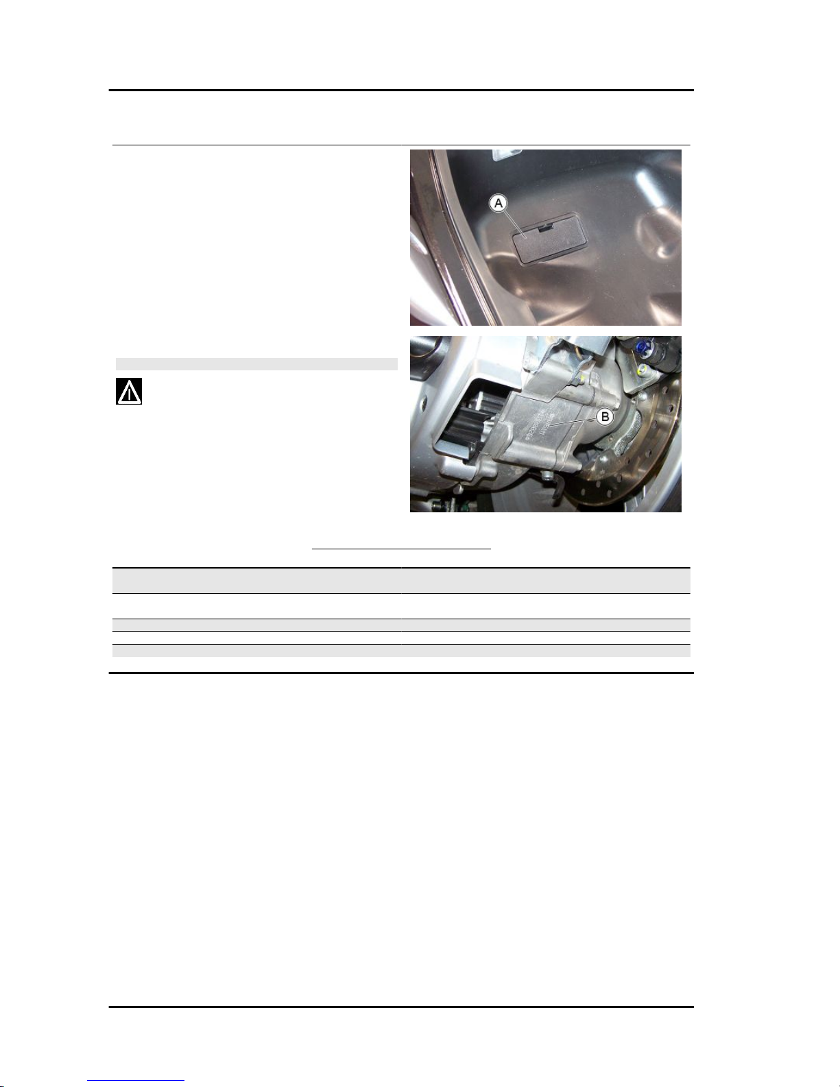
Vehicle identification
The identification registration numbers consist of
a prefix stamped on the chassis and engine "B"
respectively, followed by a number. These numbers must always be indicated on spare parts requests. To read the chassis number, remove the
relevant port "A" in the helmet compartment. We
recommend checking that the chassis registration
number stamped on the vehicle corresponds with
that on the vehicle documentation.
CAUTION
PLEASE REMIND THAT ALTERING IDENTIFICATION REGISTRATION NUMBERS CAN LEAD TO SERIOUS PENAL
SANCTIONS (IMPOUNDING OF THE VEHICLE, ETC.).
VEHICLE IDENTIFICATION
Specification
Desc./Quantity
Frame prefix (VERSION EQUIPPED WITH ABS - ASR SYS-
TEM)
ZAPM86100
Frame prefix (VERSION NOT EQUIPPED WITH ABS - ASR
SYSTEM)
ZAPM86101
Frame prefix USA/CND ZAPM860X
Engine prefix M861M
Engine prefix USA/CND M863M
Characteristics MP3 500 i.e. SPORT Business_LT_ ABS-ASR_EU_USA
(2015)
CHAR - 8
Page 9

Dimensions and mass
WEIGHTS AND DIMENSIONS
Specification
Desc./Quantity
Length 2205 mm (86.8 in)
Width 775 mm (30.5 in)
Maximum height 1460 mm (57.5 in)
Wheelbase 1540 mm (60.6 in)
Track 465 mm (18.3 in)
Kerb weight 266 kg (586 lb)
Maximum weight limit 460 kg (1014 lb)
Engine
ENGINE TECHNICAL DATA
Specification
Desc./Quantity
Type Single-cylinder, 4-stroke
Engine capacity 493 cm³
Bore x Stroke 94 x 71 mm
Compression ratio 10.5 ± 0.5 : 1
Engine idle speed 1,600 ± 100 rpm
Timing system Four valves, single overhead camshaft, chain-driven.
Valve clearance Inlet: 0.15 mm
Outlet: 0.15 mm
MAX. power 29.5 kW at 7,250 rpm
MAX. torque 45.5 Nm at 5,250 rpm
Transmission CVT expandable pulley variator with torque server, V-belt, self-
ventilating dry automatic centrifugal clutch and transmission
housing with forced-circulation air cooling.
Final reduction with gear reduction unit in oil bath.
Lubrication Engine lubrication with lobe pump (inside crankcase), chain-
driven, with double filter: mesh and paper.
MP3 500 i.e. SPORT Business_LT_ ABS-ASR_EU_USA (2015)
Characteristics
CHAR - 9
Page 10

Specification Desc./Quantity
Cooling Forced coolant circulation system.
Electric Electric starter
Ignition Highly efficient electronic inductive ignition, integrated with the
injection system, with variable advance, separate HV coil and
double spark plug.
Ignition advance Three-dimensional map managed by control unit
Spark plug NGK CR7EKB
Electrode gap 0.7 ÷ 0.9 mm
Fuel system By electronic injection with electric fuel pump.
Fuel Unleaded petrol (95 RON)
Exhaust silencer Absorption-type exhaust muffler with catalytic converter and
lambda probe.
Emissions compliance EURO 2
Transmission
TRANSMISSION
Specification Desc./Quantity
TRANSMISSION Automatic expandable pulley variator with torque server, V-
belt, automatic clutch.
Final reduction with gear reduction unit in oil bath.
Capacities
CAPACITY
Specification
Desc./Quantity
Engine oil 0.44 gal (1.7 l)
Transmission oil 15.3 in³ (250 cm³)
Cooling system fluid ~ 0.47 gal (~ 1.8 l)
Fuel tank 3.2 gal ± 0.1 (12.0 ± 0.5 l)
Electrical system
ELECTRICAL SYSTEM
Specification
Desc./Quantity
Electric Electric starter
Ignition Electronic, inductive, high efficiency, integrated with the injec-
tion system, with variable advance separate HV coil.
Ignition advance Three-dimensional map managed by control unit
Spark plug NGK CR7EKB
Alternative spark plug -
Battery 12V-12Ah
Alternator alternating current
Frame and suspensions
CHASSIS AND SUSPENSIONS
Specification
Desc./Quantity
Chassis Tubular and sheet steel
Front suspension The roll system is composed of an articulated parallelogram
suspension with die-cast aluminium control arms and two side
headstocks plus shock absorbers with hydraulic locking system
Front suspension travel 85 mm
Rear suspension Two double-acting shock absorbers, adjustable to four posi-
tions at preloading.
Characteristics MP3 500 i.e. SPORT Business_LT_ ABS-ASR_EU_USA
(2015)
CHAR - 10
Page 11

Specification Desc./Quantity
Rear suspension travel 110 mm
Brakes
BRAKES
Specification Desc./Quantity
Front brake Double disc Ø 258 with hydraulic control activated by handlebar
right lever; Braking assisted by ABS system (where available).
Rear brake Ø 240-mm disc brake with hydraulic control operated by the
handlebar left-hand lever; Braking assisted by ABS system
(where available).
Integral braking system The system operates all three discs simultaneously and is con-
trolled hydraulically via the pedal on the footrest.
Wheels and tyres
WHEELS AND TYRES
Specification Desc./Quantity
Wheel rim type Light alloy.
Front wheel rims 13" x 3.00"
Rear wheel rim 14'' x 4.50
Front tyres Tubeless 110/70 - 13" 48S
Rear tyre Tubeless 140/70 - 14" 68S
Front tyres pressure 2 bar
Rear tyre pressure (with passenger) 2.4 (2.6) bar
Tightening Torques
STEERING
Name
Torque in Nm
Steering lower ring nut (central headstock) 10 - 12 Nm (7 - 9 lb*ft)
Steering upper ring nut (central headstock) 32.5 - 40 Nm (24 - 30 lb*ft)
Handlebar fixing screw 50 - 55 Nm (37 - 41 lb*ft)
Fixing screws for the control unit U-bolts to the handlebar 7 - 10 Nm (5.2 - 7 lb*ft)
FRAME
Name
Torque in Nm
Swinging arm adjuster bushing 5 - 7 Nm (3.7 - 5.2 lb*ft)
Engine arm bolt - frame arm 32.5 - 40 Nm (24 - 30 lb*ft)
Swinging arm adjuster bushing nut 54 - 60 Nm (40 - 44 lb*ft)
Engine-swinging arm bolt 98 - 118 Nm (72 - 87 lb*ft)
Frame-swinging arm bolt 54 - 60 Nm (40 - 44 lb*ft)
Centre stand bolt 31 - 39 Nm (23 - 29 lb*ft)
FRONT SUSPENSION
Name
Torque in Nm
Lower shock absorber clamp 19 - 26 Nm (14 - 19 lb*ft)
Upper shock absorber retainer 19 - 29 Nm (14 - 21 lb*ft)
Front wheel fixing screws 19 - 24 Nm (14 - 18 lb*ft)
Tilt gripper fixing screws 20 - 25 Nm (15 - 18 lb*ft)
Steering arm bolt nut 20 - 25 Nm (15 - 18 lb*ft)
Arm coupling screws 45 - 50 Nm (33 - 37 lb*ft)
Screws fixing arms to lateral headstocks 45 - 50 Nm (33 - 37 lb*ft)
Screws fixing arms to central headstock 45 - 50 Nm (33 - 37 lb*ft)
Screws fixing the half-arm coupling flange 20 - 25 Nm (15 - 18 lb*ft)
Screws fixing roll lock disc section 20 - 25 Nm (15 - 18 lb*ft)
MP3 500 i.e. SPORT Business_LT_ ABS-ASR_EU_USA (2015)
Characteristics
CHAR - 11
Page 12

Name Torque in Nm
Side headstock upper ring nut 20 - 24 Nm (15 - 18 lb*ft)
Side headstock lower ring nut 12 - 15 Nm (9 - 11 lb*ft)
Screw fixing sliding stem to shock absorber 45 - 50 Nm (33 - 37 lb*ft)
Clamp for sliding stem locking device 6.5 - 10.5 Nm (4.8 - 8 lb*ft)
Fixing nuts for constant-velocity universal joints 18 - 20 Nm (13 - 15 lb*ft)
Potentiometer to anti-tilting device clamp 8 - 10 Nm (5.9 - 7 lb*ft)
Electric motor to anti-tilting device clamp 11 - 13 Nm (8 - 10 lb*ft)
Clamp fixing pump spindle to anti-tilting device 11 - 13 Nm (8 - 10 lb*ft)
Pump to anti-tilting device clamp 11 - 13 Nm (8 - 10 lb*ft)
Pressure switch to distribution frame 18 - 20 Nm (13 - 15 lb*ft)
Sensor to tilt gripper clamp 2.5 - 2.9 Nm (1.8 - 2.1 lb*ft)
Pipe terminals to fifth wheel check spring 7 - 11 Nm (5.2 - 8 lb*ft)
Joint to anti-tilting device pump 20 - 25 Nm (15 - 18 lb*ft)
Suspension lock calliper pipe fitting on side steering pipe 25 - 28 Nm (18 - 21 lb*ft)
REAR SUSPENSION
Name Torque in Nm
Upper shock absorber retainer 33 - 41 Nm (24 - 30 lb*ft)
Lower shock absorber clamp 33 - 41 Nm (24 - 30 lb*ft)
Shock absorber-crankcase attachment bracket 20 - 27 Nm (15 - 18 lb*ft)
Rear wheel axle 104 - 126 Nm (77 - 93 lb*ft)
Silencer arm fixing screw 27 - 30 Nm (20 - 22 lb*ft)
FRONT BRAKE
Name Torque in Nm
Calliper coupling screw 22 - 27 Nm (16 - 20 lb*ft)
Oil bleed screw 8 - 12 Nm (5.9 - 9 lb*ft)
Front brake disc screws 8 - 10 Nm (5.9 - 7 lb*ft)
Front brake pump-pipe fitting 16 - 20 Nm (12 - 15 lb*ft)
Joint pipe-calliper 20 - 25 Nm (15 - 18 lb*ft)
Screw tightening calliper to support 20 - 25 Nm (15 - 18 lb*ft)
Brake calliper pipe fitting on side steering pipe 25 - 28 Nm (18 - 21 lb*ft)
REAR BRAKE
Name
Torque in Nm
Rear brake disc screws(°) 5 - 6.5 Nm (3.7 - 4.8 lb*ft)
Rear brake calliper-pipe fitting 20 - 25 Nm (15 - 18 lb*ft)
Rigid - flexible pipe fitting 13 - 18 Nm (10 - 13 lb*ft)
Rear brake pump-pipe fitting 16 - 20 Nm (12 - 15 lb*ft)
Rear brake calliper fixing screws 41.5 - 51.5 Nm (31 - 38 lb*ft)
Parking brake - Screw tightening calliper to support (°) 24 - 27 Nm (18 - 20 lb*ft)
(°) Apply LOCTITE 243 medium-strength threadlock.
ABS SYSTEM (IF FITTED)
Name
Torque in Nm
ABS sensors tightening screws 6 - 10 Nm (4.4 - 7 lb*ft)
Screw fixing ABS control unit to support 10 - 12 Nm (7 - 9 lb*ft)
Pipe fittings - ABS control unit 13 - 18 Nm (10 - 13 lb*ft)
ABS control unit supporting bracket fixing screw 8 - 10 Nm (5.9 - 7 lb*ft)
SILENCER
Name
Torque in Nm
Silencer heat guard fixing screw 4 - 5 Nm (3 - 3.7 lb*ft)
Screw for fixing silencer to supporting arm 20 - 25 Nm (15 - 18 lb*ft)
Oxygen sensor tightening on exhaust manifold 40 - 50 Nm (30 - 37 lb*ft)
Exhaust manifold-silencer joint tightening 12 - 13 Nm (9 - 10 lb*ft)
Manifold-silencer clamp tightening 16 - 18 Nm (12 - 13 lb*ft)
LUBRICATION
Name
Torque in Nm
Oil pump cover screws 0.7 - 0.9 Nm (0.52 - 0.66 lb*ft)
Screws fixing oil pump to the crankcase 5 - 6 Nm (3.7 - 4.4 lb*ft)
Characteristics MP3 500 i.e. SPORT Business_LT_ ABS-ASR_EU_USA
(2015)
CHAR - 12
Page 13

HEAD-ENGINE BLOCK-PISTON ASSEMBLY
Name Torque in Nm
Spark plug 12 - 14 Nm (9 - 10 lb*ft)
Head fixing stud bolts 7 Nm + 90° + 90° (5.2 lb*ft + 90° + 90°)
Head fixing nuts 10 - 12 Nm (7 - 9 lb*ft)
Exhaust / intake head fixing nuts 10 - 12 Nm (7 - 9 lb*ft)
Head lubrication control jet 5 - 7 Nm (3.7 - 5.2 lb*ft)
Coolant temperature sensor 10 - 12 Nm (7 - 9 lb*ft)
Lambda probe on exhaust manifold 10 - 12 Nm (7 - 9 lb*ft)
injector fixing screw 3 - 4 Nm (2.2 - 3 lb*ft)
Counterweight screw 7 - 8.5 Nm (5.2 - 6.3 lb*ft)
Tensioner pad fixing screw 10 - 14 Nm (7 - 10 lb*ft)
Speed/phase sensor fixing screw 3 - 4 Nm (2.2 - 3 lb*ft)
Valve lifter mass stop bell fixing screws 30 - 35 Nm (22 - 26 lb*ft)
Intake manifold screws 11 - 13 Nm (8 - 10 lb*ft)
Tappet cover fixing screws 7 - 9 Nm (5.2 - 6.6 lb*ft)
Throttle body fixing screws 11 - 13 Nm (8 - 10 lb*ft)
Head fixing screws 10 - 12 Nm (7 - 9 lb*ft)
Camshaft retaining bracket screws: 4 - 6 Nm (3 - 4.4 lb*ft)
Tightener screw: 5 - 6 Nm (3.7 - 4.4 lb*ft)
Tensioner fastening screws: 11 - 13 Nm (8 - 10 lb*ft)
TRANSMISSION COVER
Name Torque in Nm
Driven pulley nut 92 - 100 Nm (68 - 74 lb*ft)
Driving pulley nut 160 - 175 Nm (118 - 129 lb*ft)
Anti-vibration roller screw 16.7 - 19.6 Nm (12 - 14 lb*ft)
M8 retainers for transmission cover 23 - 26 Nm (17 - 19 lb*ft)
M6 retainer 11 - 13 Nm (8 - 10 lb*ft)
Anti-vibration roller retainer 17 - 19 Nm (13 - 14 lb*ft)
Clutch ring nut 65 - 75 Nm (48 - 55 lb*ft)
Air duct screws 11 - 12 Nm (8 - 9 lb*ft)
Water pump cover screws 3 - 4 Nm (2.2 - 3 lb*ft)
External transmission cover screws 7 - 9 Nm (5.2 - 6.6 lb*ft)
Flywheel cover screws 11 - 13 Nm (8 - 10 lb*ft)
FLYWHEEL COVER
Name
Torque in Nm
Chain guide sliding block fastening screws 3 - 4 Nm (2.2 - 3 lb*ft)
Flywheel fixing nut 115 - 125 Nm (85 - 92 lb*ft)
Stator clamps 8 - 10 Nm (5.9 - 7 lb*ft)
Blow-by recovery duct fixing screws 3 - 4 Nm (2.2 - 3 lb*ft)
Screws fixing freewheel to flywheel 13 - 15 Nm (10 - 11 lb*ft)
Stator wiring harness guide bracket screws 3 - 4 Nm (2.2 - 3 lb*ft)
Supporting screws with bulkhead 0.3 - 0.4 Nm (0.22 - 0.30 lb*ft)
Minimum oil pressure sensor 12 - 14 Nm (9 - 10 lb*ft)
Water pump rotor 4 - 5 Nm (3 - 3.7 lb*ft)
CRANKCASE AND CRANKSHAFT
Name
Torque in Nm
Countershaft fixing nut 25 - 29 Nm (18 - 21 lb*ft)
Engine oil filter 12 - 16 Nm (9 - 12 lb*ft)
Engine oil drainage plug 24 - 30 Nm (18 - 22 lb*ft)
Engine-crankcase coupling screws 11 - 13 Nm (8 - 10 lb*ft)
Oil pump screws 5 - 6 Nm (3.7 - 4.4 lb*ft)
Gear mounting on crankshaft screws 10 - 12 Nm (7 - 9 lb*ft)
Oil pump compartment cover bulkhead screws 8 - 10 Nm (5.9 - 7 lb*ft)
COOLING
Name
Torque in Nm
Water pump rotor 4 - 5 Nm (3 - 3.7 lb*ft)
Water pump cover screws 3 - 4 Nm (2.2 - 3 lb*ft)
Thermostat cover screws 3 - 4 Nm (2.2 - 3 lb*ft)
MP3 500 i.e. SPORT Business_LT_ ABS-ASR_EU_USA (2015)
Characteristics
CHAR - 13
Page 14

Name Torque in Nm
Bleed screw 3 Nm (2.2 lb*ft)
Overhaul data
Assembly clearances
Cylinder - piston assy.
HEIGHT TO MEASURE THE PISTON
Specification
Desc./Quantity
A 10 mm
B 43 mm
CYLINDER - PISTON
Specification
Desc./Quantity
Cylinder diameter C 94 +0.018-0.01mm
Piston diameter P 93.968 - ±0.014 mm
COUPLING CATEGORIES
Name
Initials Cylinder Piston Play on fitting
Cylinder- Piston A 93.990÷93.997 93.954÷93.961 0.029÷0.043
Cylinder- Piston B 93.997÷93.004 93.961÷93.968 0.029÷0.043
Cylinder- Piston C 94.004÷94.011 93.968÷93.975 0.029÷0.043
Cylinder- Piston D 94.011÷94.018 93.975÷93.982 0.029÷0.043
Characteristics MP3 500 i.e. SPORT Business_LT_ ABS-ASR_EU_USA
(2015)
CHAR - 14
Page 15

N.B.
THE PISTON MUST BE INSTALLED WITH THE ARROW FACING TOWARDS THE EXHAUST SIDE,
THE PISTON RINGS MUST BE INSTALLED WITH THE WORD «TOP» OR THE STAMPED MARK
FACING UPWARDS.
Piston rings
* Fit piston rings «2» and «3» with the mark «TOP» facing up.
** Position the opening in the rings as shown in this figure.
*** Value «A» of the sealing ring inside the cylinder.
Check the size of the sealing ring opening:
Compression ring: 0.15 ÷ 0.35 mm. Max. value: 0.5 mm
Scraper ring: 0.25 ÷ 0.50 mm. Max. value: 0.65 mm
Scraper ring: 0.25 ÷ 0.50 mm. Max. value: 0.65 mm
Rings/slots coupling clearances:
Carefully clean the sealing rings housings.
Check coupling clearances by placing a thickness
gauge between the ring and the slot as shown in
the figure.
Top ring: Standard coupling clearance:
0.01÷0.06 mm
Maximum clearances allowed after use: 0.10
mm
MP3 500 i.e. SPORT Business_LT_ ABS-ASR_EU_USA (2015)
Characteristics
CHAR - 15
Page 16

Middle ring: Standard coupling clearance:
0.02÷0.07 mm
Maximum clearances allowed after use: 0.10
mm
Oil scraper ring: Standard coupling clearance: 0.01÷0.06 mm
Maximum clearances allowed after use: 0.10
mm
If clearances measured exceed the maximum values specified in the table, the piston should be
replaced by a new one.
Crankcase - crankshaft - connecting rod
AXIAL CLEARANCE BETWEEN CRANKSHAFT AND CONNECTING ROD
Name
Description Dimensions Initials Quantity
Transmission-side
shoulder
1 ± 0.025 A D = 0.20 ÷ 0.50
Half-shaft, transmission
side
20.9 - 0.05 B D = 0.20 ÷ 0.50
Connecting rod 22 0.10 - 0.15 C D = 0.20 ÷ 0.50
Characteristics MP3 500 i.e. SPORT Business_LT_ ABS-ASR_EU_USA
(2015)
CHAR - 16
Page 17

Name Description Dimensions Initials Quantity
Flywheel-side shoulder 1.8 ± 0.025 F D = 0.20 ÷ 0.50
Flywheel side half-shaft 19.6 + 0.05 E D = 0.20 ÷ 0.50
Complete crankshaft 65.5 +0.1 -0.05 G D = 0.20 ÷ 0.50
Diameter of crankshaft bearings.
Measure the bearings on both axes x-y.
CRANKSHAFT
Specification Desc./Quantity
Cat. 1 Standard diameter: 40.010 ÷ 40.016
Cat. 2 Standard diameter: 40.016 ÷ 40.022
Crankshaft alignment
Specific tooling
020335Y Dial gauge magnetic support
MAXIMUM OFF-LINE ALLOWED
Specification
Desc./Quantity
A = 0.15 mm
B = 0.010 mm
C = 0.010 mm
D = 0.10 mm
MP3 500 i.e. SPORT Business_LT_ ABS-ASR_EU_USA (2015)
Characteristics
CHAR - 17
Page 18

Characteristic
Crankshaft-crankcase axial clearance (H)
0.1 ÷ 0.405 mm (when cold)
Compression ratio
10.5: 1
Slot packing system
Shimming system to control compression ratio
MEASUREMENT «A» IS A PROTRUSION OR RECESS VALUE OF THE PISTON CROWN COMPARED WITH THE CYLINDER PLANE.
MEASUREMENT «A» ALLOWS TO DETERMINE THE
THICKNESS OF THE GASKET «B» THAT HAS TO BE FITTED INTO THE CYLINDER BASE IN ORDER TO RESTORE
THE COMPRESSION RATIO. THE MORE THE PLANE
FORMED BY THE PISTON CROWN PROTRUDES BEYOND
THE PLANE FORMED BY THE CYLINDER UPPER END,
THE THICKER THE GASKET TO BE USED AT THE CYLINDER BASE «B» SHOULD BE. ON THE OTHER HAND, THE
MORE THE PISTON CROWN IS RECESSED INTO THE CYLINDER TOP PLANE, THE SMALLER THE GASKET THICKNESS.
Characteristic
Compression ratio
Characteristics MP3 500 i.e. SPORT Business_LT_ ABS-ASR_EU_USA
(2015)
CHAR - 18
Page 19

10.5: 1
BASE GASKET THICKNESS
Name Measure A Thickness
MEASURE TAKEN «A» - 0.185 ÷ - 0.10 0.4 ± 0.05
MEASURE TAKEN «A» - 0.10 ÷ + 0.10 0.6 ± 0.05
MEASURE TAKEN «A» + 0.10 ÷ + 0.185 0.8 ± 0.05
N.B.
VALUES INDICATED WITH «-» REFER TO RECESSES OF THE PISTON CROWN FROM THE
CYLINDER PLANE.
N.B.
SIZE «A» MUST BE MEASURED WITHOUT ANY GASKET FITTED AT «B»
Products
RECOMMENDED PRODUCTS TABLE
Product Description Specifications
AGIP GEAR SAE 80W-90 Lubricant for gearboxes and transmis-
sions.
API GL-4
eni i-Ride PG 5W-40 Synthetic based lubricant for high-per-
formance four-stroke engines.
JASO MA, MA2 - API SL - ACEA A3
AGIP FILTER OIL Special product for the treatment of foam
filters.
-
AGIP GP 330 Water repellent stringy calcium spray
grease.
R.I.D./A.D.R. 2 10°b) 2 R.I.Na. 2.42 I.A.T.A. 2 - I.M.D.G. class 2 UN 1950
Page 9022 EM 25-89
AGIP BRAKE 4 Brake fluid. SAE J 1703 -FMVSS 116 - DOT 3/4 - ISO
4925 - CUNA NC 956 DOT 4 synthetic
fluid
AGIP PERMANENT SPECIAL Ethylene glycol-based antifreeze fluid
with organic inhibition additives. Red,
ready to use.
ASTM D 3306 - ASTM D 4656 - ASTM D
4985 - CUNA NC 956-16
MP3 500 i.e. SPORT Business_LT_ ABS-ASR_EU_USA (2015)
Characteristics
CHAR - 19
Page 20

INDEX OF TOPICS
TOOLING TOOL
Page 21
SPECIFIC TOOLS
Stores code Description
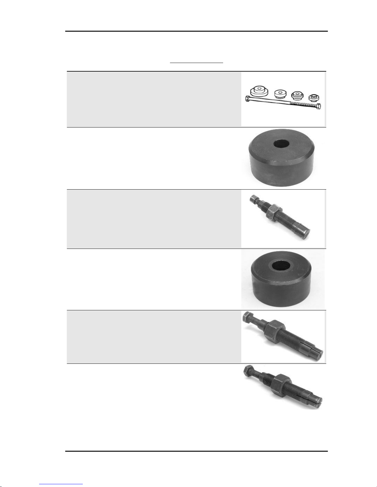
001330Y Tool for fitting steering seats
001467Y002 Driver for OD 73 mm bearing
001467Y006 Pliers to extract 20 mm bearings
001467Y007 Bell for OD 54-mm bearings
001467Y008 Calliper to extract 17-mm diameter bear-
ings
001467Y014 Calliper to extract 15-mm diameter bear-
ings
MP3 500 i.e. SPORT Business_LT_ ABS-ASR_EU_USA (2015) Tooling
TOOL - 21
Page 22
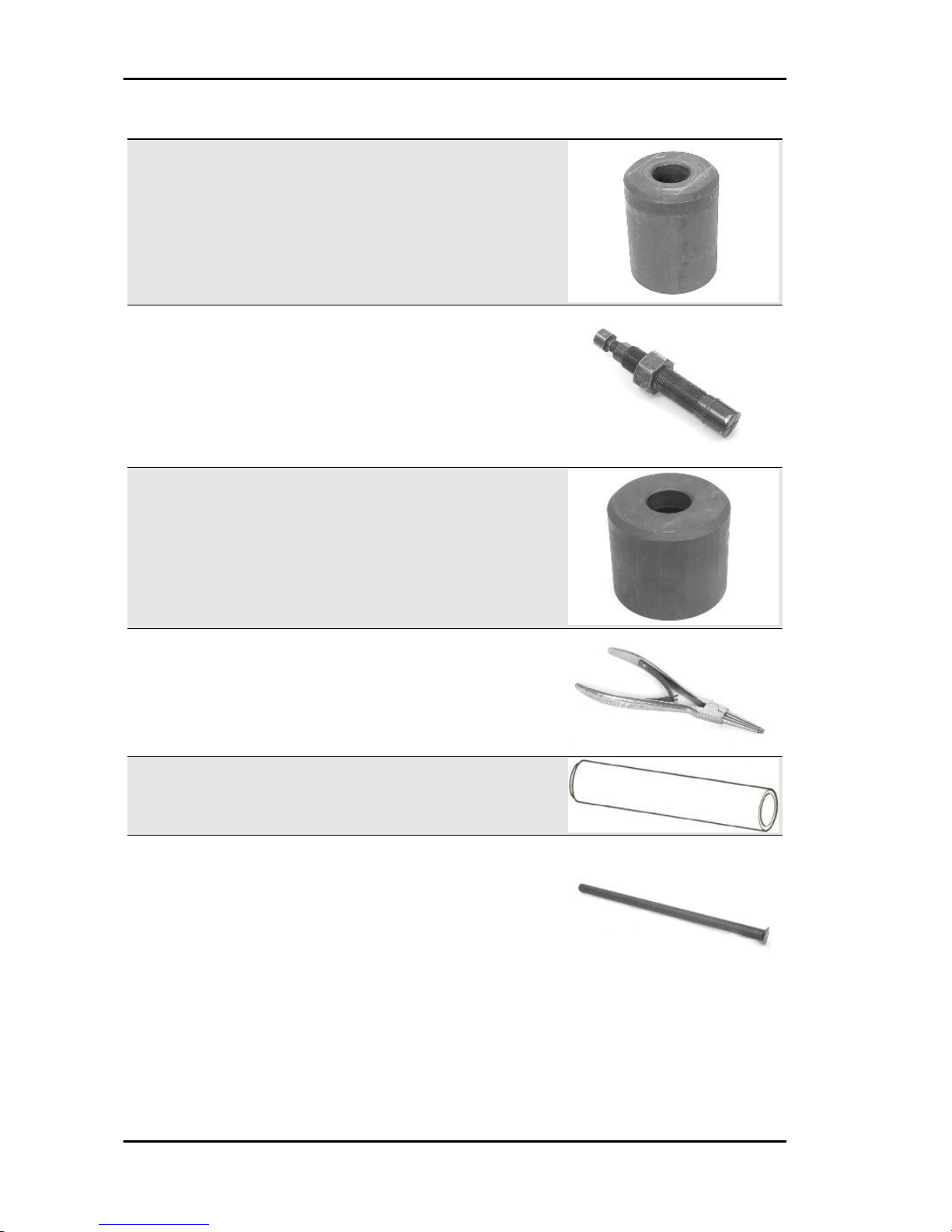
Stores code Description
001467Y031 Bell
001467Y034 Calliper to extract 15-mm diameter bear-
ings
001467Y035 Bell for 47-mm outside diameter bearings
002465Y Calliper for circlips
006029Y Punch for fitting steering bearing seat on
steering tube
020004Y Punch to remove steering bearings from
headstock
Tooling MP3 500 i.e. SPORT Business_LT_ ABS-ASR_EU_USA (2015)
TOOL - 22
Page 23

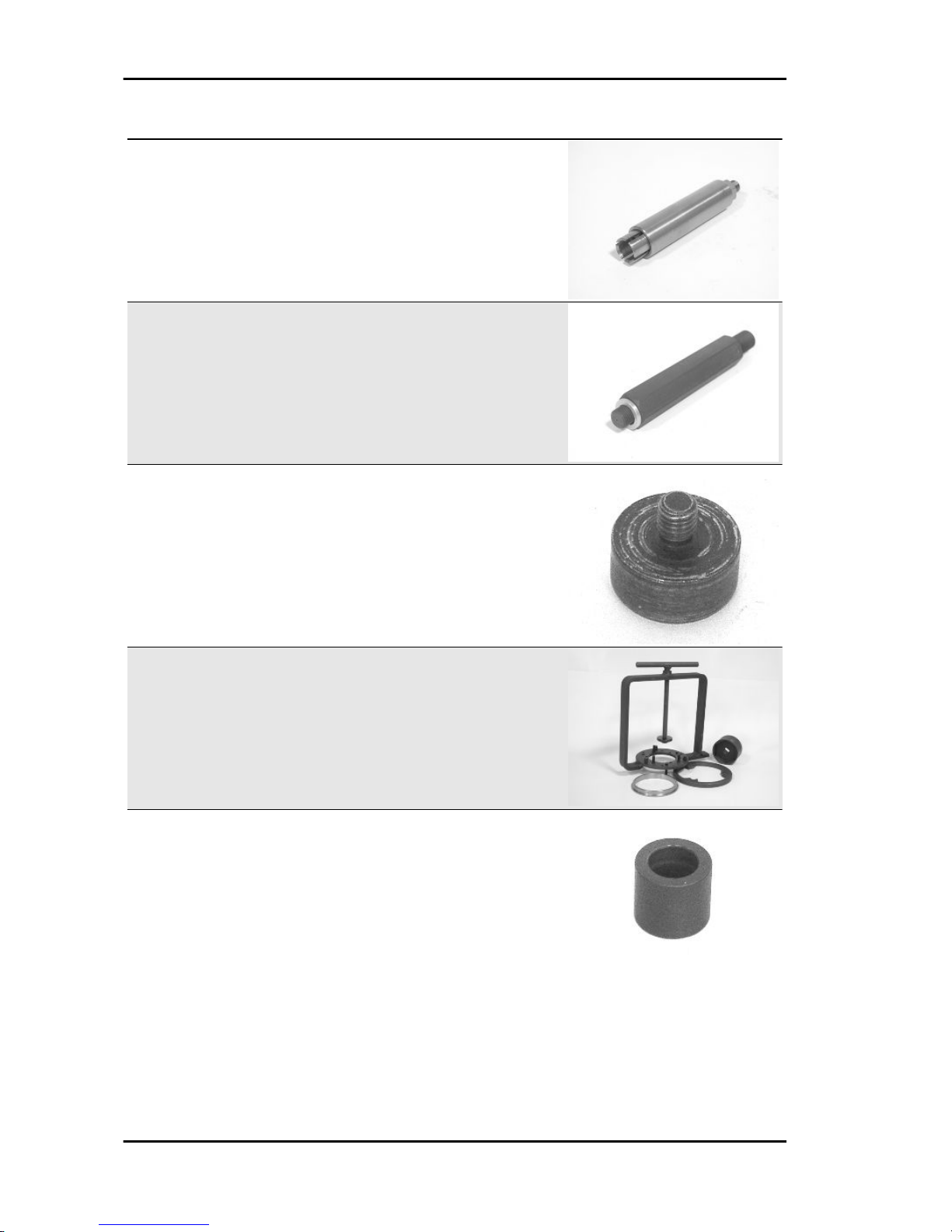
Stores code Description
020055Y Wrench for steering tube ring nut
020150Y Air heater support
020151Y Air heater
020193Y Gauge for oil pressure check
020201Y Spacer bushing driving tube
020262Y Crankcase splitting strip
020306Y Punch for fitting the valve seal rings
MP3 500 i.e. SPORT Business_LT_ ABS-ASR_EU_USA (2015) Tooling
TOOL - 23
Page 24

Stores code Description
020329Y Vacuum pump Mity-Vac
020330Y Stroboscopic light for timing checking
020331Y Digital multimeter
020648Y Single battery charger
020335Y Dial gauge magnetic support
020357Y 32 x 35 mm adaptor
020358Y 37 x 40 mm adaptor
Tooling MP3 500 i.e. SPORT Business_LT_ ABS-ASR_EU_USA (2015)
TOOL - 24
Page 25

Stores code Description
020359Y 42 x 47-mm adaptor
020360Y 52 x 55-mm adaptor
020364Y 25-mm Guide
020376Y Adapter handle
020382Y012 bush (valve removing tool)
020412Y 15 mm guide
020424Y Punch for fitting driven pulley roller casing
MP3 500 i.e. SPORT Business_LT_ ABS-ASR_EU_USA (2015) Tooling
TOOL - 25
Page 26
Stores code Description
020431Y Valve oil seal extractor
020434Y Fitting for oil pressure check
020439Y 17 mm guide
020444Y Tool for fitting/removing the clutch on the
driven pulley
020456Y Ø24 mm adaptor
Tooling MP3 500 i.e. SPORT Business_LT_ ABS-ASR_EU_USA (2015)
TOOL - 26
Page 27

Stores code Description
020458Y Puller for lower bearing on steering tube
020459Y Punch for fitting bearing on steering tube
020922Y Diagnosis Tool
020467Y Flywheel extractor
020468Y Piston fitting ring
020470Y Pin snap ring fitting tool
MP3 500 i.e. SPORT Business_LT_ ABS-ASR_EU_USA (2015) Tooling
TOOL - 27
Page 28
Stores code Description
020471Y Pin for countershaft timing
020472Y Flywheel lock wrench
020474Y Driving pulley lock wrench
020475Y Piston position checking tool
020476Y Stud bolt set
020478Y Punch for roller casing
Tooling MP3 500 i.e. SPORT Business_LT_ ABS-ASR_EU_USA (2015)
TOOL - 28
Page 29

Stores code Description
020479Y Countershaft lock wrench
020480Y Fuel pressure check set
020482Y Engine support
020483Y 30 mm guide
020512Y Piston fitting fork
020527Y Engine support base
020604Y011 Fitting adapter
MP3 500 i.e. SPORT Business_LT_ ABS-ASR_EU_USA (2015) Tooling
TOOL - 29
Page 30

Stores code Description
020565Y Flywheel lock calliper spanner
020481Y004 Parking control unit interface wiring
020646Y Parallelogram and steering positioning
tool
020647Y Toe-in checking tool
020647Y028 MP3 LT Toe-in tool (tricycle)
020661Y Water pump overall seal replacement kit
Tooling MP3 500 i.e. SPORT Business_LT_ ABS-ASR_EU_USA (2015)
TOOL - 30
Page 31

INDEX OF TOPICS
MAINTENANCE MAIN
Page 32

N.B.
THE UNITS OF MEASUREMENT CONTAINED IN THIS CHAPTER ARE EXPRESSED IN TERMS
OF THE DECIMAL METRIC SYSTEM. TO REFER TO THE UNIT OF MEASUREMENT EXPRESSED
IN TERMS OF THE ANGLO-SAXON SYSTEM, SEE THE «CHARACTERISTICS» CHAPTER.
SERVICE ICON RESET
When switching to «ON», immediately after the ignition check, if there are less than 300 km (187.5
miles) to the next scheduled service, the corresponding icon flashes for 5 seconds. Once the
service mileage has been reached, the icon remains steadily on until it is reset. The icon reset is
carried out by pressing the button «SET» for more
than 10 seconds when switching to «ON»: the icon
with the key, after the ignition check, must flash
with a frequency of 1 Hz and then turn off after 10
seconds to indicate the performed reset. If the button is released before the 10 seconds, the icon is
not reset.
ADJUSTMENT PROCEDURE OF THE RING NUTS OF THE SIDE HEADSTOCKS
- Remove the windshield.
- Remove the central cover fixed to the joints on
the legshield.
- Remove the two indicated daylight running light
fixing screws.
- Remove the daylight running light by disconnecting the connector.
Maintenance MP3 500 i.e. SPORT Business_LT_ ABS-ASR_EU_USA
(2015)
MAIN - 32
Page 33

- Remove the two screws located inside the glovebox on the dashboard.
- Remove the four screws indicated and recover
the related spacers.
- Undo the two screws indicated, then remove the
spoiler.
- Remove the two headlight upper fixing screws.
MP3 500 i.e. SPORT Business_LT_ ABS-ASR_EU_USA (2015)
Maintenance
MAIN - 33
Page 34

- Remove the Piaggio clip-on badge, fixed to the
joint, by acting on the indicated slot.
- Remove the indicated screw and remove the radiator grille frame.
- Unscrew the four indicated screws and remove
the radiator grille.
- Working on both sides of the vehicle, remove the
two screws in the wheel housing.
Maintenance MP3 500 i.e. SPORT Business_LT_ ABS-ASR_EU_USA
(2015)
MAIN - 34
Page 35

- Unscrew the four indicated screws and remove
the front radiator cover.
- Remove the two lower fastening screws.
- Disconnect the connector and remove the headlight.
- Undo the four indicated screws on the leg shield
back plate.
MP3 500 i.e. SPORT Business_LT_ ABS-ASR_EU_USA (2015)
Maintenance
MAIN - 35
Page 36

- Working on both sides of the vehicle, unscrew the
two indicated screws and remove the spoiler support plastic.
- Remove the two indicated screws from both sides
of the vehicle, located inside the wheel housing.
- Detach the shield from the vehicle, complete with
side bumpers and turn indicators and disconnect
the connectors of the turn indicators.
WARNING
DURING THE REFITTING, PAY PARTICULAR ATTENTION
TO THE CORRECT POSITION OF THE TWO SPOILER SUPPORT PLASTICS, REFERRING TO THE INDICATIONS ON
THE PLASTIC.
Once the plastics have been remove the ring nuts
of the side headstock of the front suspension can
be reached
Unscrew the upper ring nut
Bring the upper ring nut to the end of the headstock
thread of the side suspension
Maintenance MP3 500 i.e. SPORT Business_LT_ ABS-ASR_EU_USA
(2015)
MAIN - 36
Page 37

Tighten the lower ring nut to the specified torque
with the appropriate key.
Locking torques (N*m)
Side headstock lower ring nut 12 - 15
Screw the upper ring nut until it stops
Tighten upper ring nut to the specified torque with
the appropriate key.
Specified torque: 20 to 24 Nm.
Carry out the assembly of the plastic covers in reverse order to the disassembly.
Specific tooling
020892y Steering side headstock ring nut key
Locking torques (N*m)
Side headstock upper ring nut 20 to 24
Maintenance chart
SCHEDULED MAINTENANCE TABLE
I: CHECK AND CLEAN, ADJUST, LUBRICATE OR REPLACE IF NECESSARY.
C: CLEAN, R: REPLACE, A: ADJUST, L: LUBRICATE
* Replace every 2 years
Km x 1,000
1 5 10 15 20 25 30 35 40 45 50 55 60 65 70 75 80
Safety fasteners I I I I I
Throttle control A A A A A A A A A
Engine oil filter R R R R R R R R R
Electrical system I I I I I I I I I
Coolant level * I I I I I I I I I
Brake oil level* I I I I I I I I I
Engine oil R I R I R I R I R I R I R I R I R
Brake pads I I I I I I I I I I I I I I I I I
Tyre pressure and wear I I I I I I I I I
Vehicle and brake test - test drive I I I I I I I I I
Hub oil R I R I R I R I R
Centre and side steering A A A A A A A A A
Parking control unit software upgrading
(if available)
I I I I I I I I I I I I I I I I I
Centre stand L L L L L L L L L L L L L L L L
Drive belt R R R R R R R R
Air filter C I C I C I C I
MP3 500 i.e. SPORT Business_LT_ ABS-ASR_EU_USA (2015)
Maintenance
MAIN - 37
Page 38

Km x 1,000 1 5 10 15 20 25 30 35 40 45 50 55 60 65 70 75 80
Sliding shoes / CVT rollers R R R R R R R R
Suspension I I I I I I I I
Spark plugs R R R R R R R R
Roll lock calliper control cable A A A A A A A A
Valve clearance I I I I
Operation time 105'10' 190'10' 220'10' 190'10' 220'10' 190'10' 220'10' 190'10' 22
0'
Versions for market USA-CND
SCHEDULED MAINTENANCE TABLE
I: CHECK AND CLEAN, ADJUST, LUBRICATE OR REPLACE IF NECESSARY.
C: CLEAN, R: REPLACE, A: ADJUST, L: LUBRICATE
* Replace every 2 years
km x 1,000 (mi x 1000) 1
(0.
6)
5
(3.
1)
10
(6.
2)
15
(9.
3)
20
(12
.4)
25
(15
.5)
30
(18
.6)
35
(21
.7)
40
(24
.9)
45
(28
.0)
50
(31
.1)
55
(34
.2)
60
(37
.3)
65
(40
.4)
70
(43
.5)
75
(46
.6)
80
(49
.7)
Safety fasteners I I I I I
Throttle control A A A A A A A A A
Engine oil filter R R R R R R R R R
Electrical system I I I I I I I I I
Coolant level * I I I I I I I I I
Brake oil level* I I I I I I I I I
Engine oil R I R I R I R I R I R I R I R I R
Brake pads I I I I I I I I I I I I I I I I I
Tyre pressure and wear I I I I I I I I I
Vehicle and brake test - test drive I I I I I I I I I
Hub oil R I R I R I R I R
Centre and side steering A A A A A A A A A
Parking control unit software upgrading
(if available)
I I I I I I I I I I I I I I I I I
Centre stand L L L L L L L L L L L L L L L L
Drive belt R R R R R R R R
Air filter C I C I C I C I
Sliding shoes / CVT rollers R R R R R R R R
Suspension I I I I I I I I
Spark plugs R R R R R R R R
Roll lock calliper control cable A A A A A A A A
Valve clearance I I I I
Operation time 105'10' 190'10' 220'10' 190'10' 220'10' 190'10' 220'10' 190'10' 22
0'
Checking the spark advance
The ignition advance is electronically determined
based on the parameters known by the control
unit. This is why it is not possible to measure the
reference values based on the engine rpm. The
ignition advance value is detectable at any time
using the diagnostic tester. It is possible to check
whether the ignition advance determined by the
injection system matches the value actually activated on the engine, by means of the stroboscopic
light.
Maintenance MP3 500 i.e. SPORT Business_LT_ ABS-ASR_EU_USA
(2015)
MAIN - 38
Page 39

Proceed as follows:
- Remove the spark plugs.
- Remove the transmission crankcase.
- Rotate the driving pulley fan until the reference
marks between the flywheel and flywheel cover
meet as shown in the photograph.
- Bring the reference mark onto the transmission
side between the fan and the transmission cover
as shown in the photograph.
- Refit the spark plugs.
- Refit the plastic cap on the flywheel cover.
- Adjust the spark gap to the contact position (no
reference mark visible) and install it on the engine
between the spark plugs and spark plug caps.
- Connect the induction clamp to the spark gap
cable respecting the proper polarity (the arrow on
the clamp must be pointing at the spark plug).
- Connect the diagnostic tool.
- Start the engine.
- On the diagnostic tool, select the function «PA-
RAMETERS».
- Set the stroboscopic light control to the traditional
four-stroke engine position (1 spark, 2 revs).
- Check that the real values of rpm and ignition
advance match those measured using the diagnostic tool.
If the values do not correspond, check:
- distribution timing
- rpm timing sensor
- injection control unit
MP3 500 i.e. SPORT Business_LT_ ABS-ASR_EU_USA (2015)
Maintenance
MAIN - 39
Page 40

Specific tooling
020922Y Diagnosis Tool
020330Y Stroboscopic light for timing checking
020621Y HV cable extraction adaptor
Spark plug
Remove the port on the left-hand side panel of the
vehicle by undoing the fixing screw and using a
small screwdriver in the rear recess shown in the
figure, then do the following:
- Disconnect the HV wire caps «A» of the spark
plugs;
- Unscrew the spark plugs using the wrench supplied;
- Upon refitting, place the spark plugs at the required angle and tighten by hand until it is finger
tight;
- Use the wrench only for final tightening of the
spark plug;
- Place cap «A» fully over the spark plugs
- Refit the port making sure the rear hook is inser-
ted.
WARNING
THE SPARK PLUG MUST BE REMOVED WHEN THE ENGINE IS COLD. REPLACE THE SPARK PLUG AS INDICATED IN THE SCHEDULED MAINTENANCE TABLE. THE
USE OF ELECTRONIC CENTRAL UNITS AND OF NONCOMPLIANT ELECTRONIC IGNITIONS OR SPARK PLUGS
OTHER THAN THOSE PRESCRIBED MAY SERIOUSLY
DAMAGE THE ENGINE.
N.B.
USING SPARK PLUGS OTHER THAN THE INDICATED
TYPE OR SHIELDLESS SPARK PLUG CAPS CAN CAUSE
ELECTRICAL SYSTEM FAILURES.
Characteristic
Spark plug
NGK CR7EKB
Electric characteristic
Electrode gap
0.7 - 0.8 mm
Maintenance MP3 500 i.e. SPORT Business_LT_ ABS-ASR_EU_USA
(2015)
MAIN - 40
Page 41

Hub oil
Check
- Rest the vehicle on its centre stand on level
ground.
- Unscrew the dipstick «A», dry it with a clean rag
and then reinsert it, screwing it tightly into
place.
- Extract the dipstick checking that the oil level is
between the MAX and MIN index marks; if the level is below the MIN mark, it needs to be filled up
with the right amount of hub oil.
-Screw up the oil dipstick again and make sure it
is locked properly into place.
Replacement
- Remove the oil filler plug «A».
- Unscrew the oil drainage cap «B» and drain out
all the oil.
- Screw in the drainage cap again and fill the hub
with the prescribed oil.
Recommended products
AGIP GEAR SAE 80W-90 Lubricant for gearboxes and transmissions.
API GL-4
Characteristic
Rear hub oil
Capacity approximately 250 cc
MP3 500 i.e. SPORT Business_LT_ ABS-ASR_EU_USA (2015)
Maintenance
MAIN - 41
Page 42
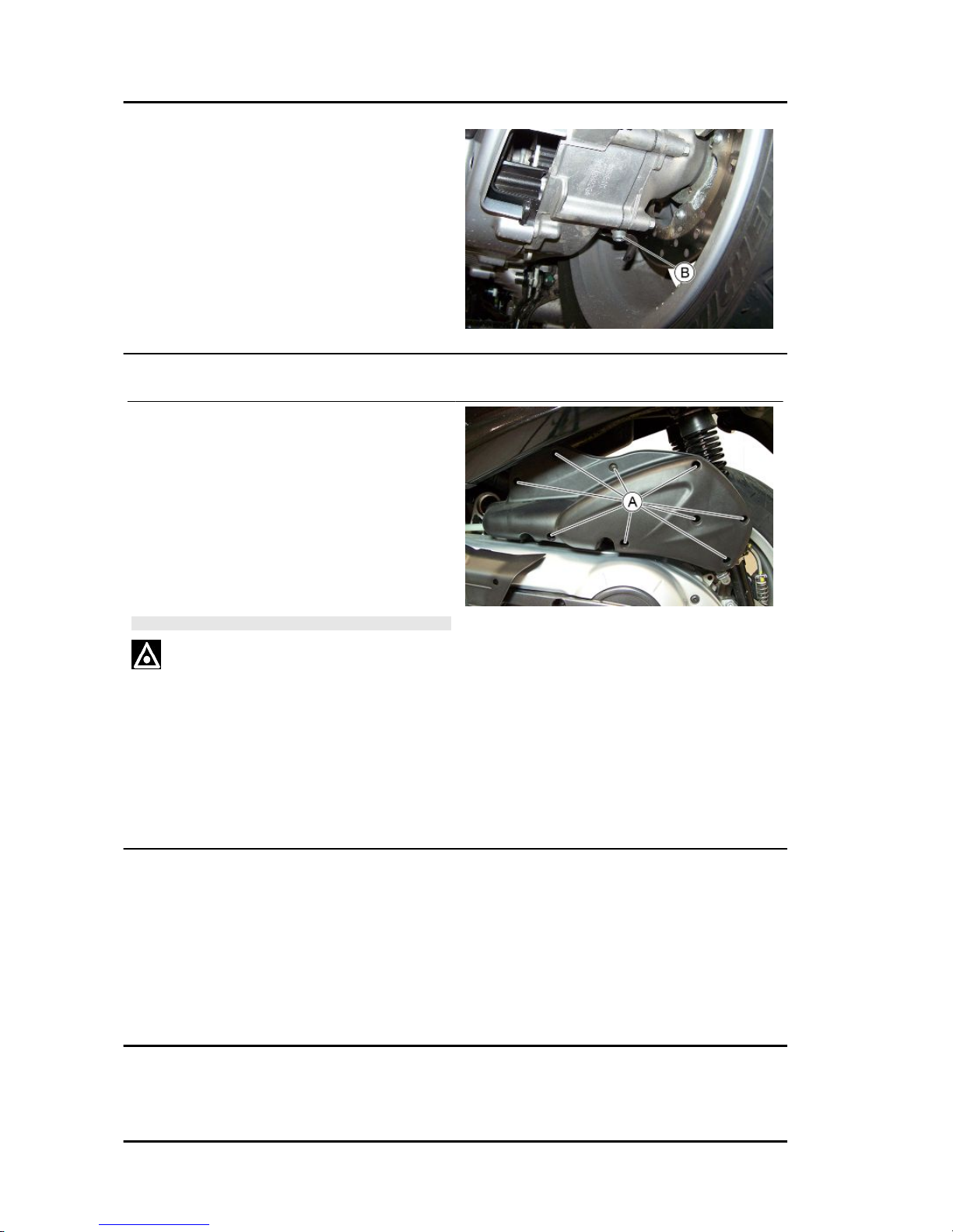
Air filter
- Unscrew the nine fixing screws «A» and remove
the air filter cover.
- Wash the sponge with water and mild soap.
- Dry it with a clean cloth and short blasts of compressed air.
- Gently squeeze the filtering element with your
hands but do not wring it; allow it to drip dry and
then refit.
CAUTION
IF THE VEHICLE IS USED ON DUSTY ROADS IT IS NECESSARY TO CARRY OUT MAINTENANCE CHECKS OF
THE AIR FILTER MORE OFTEN TO AVOID DAMAGING THE
ENGINE.
Recommended products
AGIP FILTER OIL Special product for the treatment of foam filters.
-
Engine oil
In four stroke engines, the engine oil is used to lubricate the timing elements, the bench bearings and
the thermal group. An insufficient quantity of oil can cause serious damage to the engine.
In all four stroke engines, the deterioration of the oil characteristics, or a certain consumption should
be considered normal, especially if during the run-in period. Consumption levels in particular can be
influenced by the conditions of use (e.g.: oil consumption increases when driving at "full throttle".
Maintenance MP3 500 i.e. SPORT Business_LT_ ABS-ASR_EU_USA
(2015)
MAIN - 42
Page 43

Replacement
Change oil and replace filter as indicated in the
scheduled maintenance table. Empty the engine
by draining the oil through drainage plug «B».
To facilitate oil drainage, loosen the cap/dipstick
«A».
Once all the oil has drained through the drainage
hole, unscrew the oil cartridge filter and remove it.
Make sure the pre-filter and drainage plug O-rings
are in good conditions.
Lubricate them and refit the mesh filter and the oil
drainage plug, screwing them up to the prescribed
torque.
Refit the new cartridge filter being careful to lubricate the O-ring before fitting it.
Change the engine oil.
Since a certain quantity of oil still remains in the
circuit, engine oil must be added through plug
«A». Then start up the vehicle, leave it running for
a few minutes and switch it off: After about five minutes, check the level and, if necessary, top-up but
never exceeding the MAX level reference mark.
The cartridge filter must be replaced every time the
oil is changed. Use new oil of the recommended
type for topping up and changing purposes.
N.B.
MP3 500 i.e. SPORT Business_LT_ ABS-ASR_EU_USA (2015)
Maintenance
MAIN - 43
Page 44

THE ENGINE MUST BE HOT WHEN THE OIL IS CHANGED.
Recommended products
eni i-Ride PG 5W-40 Synthetic based lubricant
for high-performance four-stroke engines.
JASO MA, MA2 - API SL - ACEA A3
Locking torques (N*m)
Engine oil filter 12 - 16 Engine oil drainage plug
24 to 30
Check
This operation must be carried out with the engine
cold and following the procedure below:
- Place the vehicle on its centre stand and on flat
ground.
- Unscrew the cap/dipstick «A», dry it with a clean
cloth and reinsert it, screwing it all the way
down.
- Remove the cap/dipstick again and check that
the level is between the min and max reference
marks; top-up, if required.
If the check is carried out after the vehicle has
been used, and therefore with a hot engine, the
level will be lower; in order to carry out a correct
check, wait at least 10 minutes after the engine
has been stopped so as to get the correct level.
Engine oil top-up
The oil should be topped up after having checked
the level and in any case by adding oil without
ever exceeding the MAX. level.
Restoring the level from the MIN to the MAX marks
requires approx. 400 m³ of oil.
Engine oil filter
Change oil and replace filter as indicated in the scheduled maintenance table. Use new oil of the recommended type for topping up and changing purposes.
Maintenance MP3 500 i.e. SPORT Business_LT_ ABS-ASR_EU_USA
(2015)
MAIN - 44
Page 45

Make sure the pre-filter and drainage plug O-rings are in good conditions. Lubricate them and refit the
mesh filter and the oil drainage plug, screwing them up to the prescribed torque. Refit the new cartridge
filter being careful to lubricate the O-ring before fitting it. Change the engine oil.
Recommended products
eni i-Ride PG 5W-40 Synthetic based lubricant for high-performance four-stroke engines.
JASO MA, MA2 - API SL - ACEA A3
Oil pressure warning light
The vehicle is equipped with a telltale light on the
dashboard that lights up when the key is turned to
the «ON» position. However, this light should
switch off once the engine has been started.
If the light turns on during braking, at idling
speed or while turning a corner, it is necessary
to check the oil level and the lubrication system.
Checking the ignition timing
- Remove the plastic cap on the flywheel cover
-Turn the flywheel until the reference mark «T» on
the rotor matches the reference mark on the flywheel cover as shown in the figure (TDC). Make
sure that the 4V reference point on the camshaft
control pulley is aligned with the reference point on
the head as shown in the second figure. If the reference is opposite the indicator on the head, turn
the crankshaft once more.
For the use of this reference mark, remove the
spark plug and turn the engine in the direction that
is the reverse of the normal direction using a calliper spanner applied to the camshaft command
pulley casing.
MP3 500 i.e. SPORT Business_LT_ ABS-ASR_EU_USA (2015)
Maintenance
MAIN - 45
Page 46

Cooling system
Check coolant level when the engine is cold as indicated in the scheduled maintenance table, following the steps below:
Place the vehicle on its centre stand and on flat
ground.
- Unscrew the screw shown in the figure and remove the expansion tank cover.
- Top up if the coolant level by undoing the plug
«A», if the coolant level is near or below the level
edge MIN. The coolant level should always be between the MIN and MAX levels.
-The coolant consists of an ethylene glycol and
corrosion inhibitor based demineralised water- antifreeze solution mix.
CAUTION
DO NOT EXCEED THE MAX. LEVEL WHEN FILLING SO AS
TO AVOID THE COOLANT ESCAPING FROM THE EXPANSION TANK WHEN THE VEHICLE IS IN USE.
Recommended products
AGIP PERMANENT SPEZIAL Ethylene glycolbased antifreeze fluid with organic inhibition
additives. Red, ready to use.
ASTM D 3306 - ASTM D 4656 - ASTM D 4985 CUNA NC 956-16
Braking system
Maintenance MP3 500 i.e. SPORT Business_LT_ ABS-ASR_EU_USA
(2015)
MAIN - 46
Page 47

Level check
FRONT AND REAR BRAKING SYSTEM LEVEL
CHECK
The front and rear brake fluid reservoirs are both
positioned on the handlebars. Proceed as follows:
- Rest the vehicle onto the centre stand, with the
handlebar centred.
- Check the fluid level through the sight glass. A
drop in the brake fluid level may be caused by pad
wear.
INTEGRAL BRAKING SYSTEM LEVEL CHECK
- Rest the vehicle on its centre stand on level
ground.
- Remove the inspection cover and check that the
brake fluid inside the reservoir is not below the
recommended level.
- A drop in the brake fluid level may be caused by
pad wear.
Top-up
FRONT AND REAR BRAKING SYSTEM TOPPING UP
For both brake pumps, proceed as follows:
- Loosen the two fixing screws and remove the
reservoir cover; top-up with the recommended fluid and without exceeding the maximum mark.
Under standard climatic conditions, replace fluid
as indicated in the scheduled maintenance table.
WARNING
ONLY USE DOT 4-CLASSIFIED BRAKE FLUID. BRAKE
CIRCUIT FLUID IS VERY CORROSIVE; MAKE SURE THAT
IT DOES NOT COME INTO CONTACT WITH THE PAINTWORK.
CAUTION
MP3 500 i.e. SPORT Business_LT_ ABS-ASR_EU_USA (2015)
Maintenance
MAIN - 47
Page 48

MAKE SURE THE BRAKE FLUID DOES NOT GET INTO
YOUR EYES OR ON YOUR SKIN OR CLOTHES. IF THIS
HAPPENS ACCIDENTALLY, WASH WITH WATER.
Recommended products
AGIP BRAKE 4 Brake fluid.
SAE J 1703 -FMVSS 116 - DOT 3/4 - ISO 4925 CUNA NC 956 DOT 4 synthetic fluid
INTEGRAL BRAKING SYSTEM LEVEL TOPPING UP
- Remove the inspection cover, unscrew the tank
cap and top up using the recommended product.
- If there is air in the circuit, bleed the system.
CAUTION
AIR INSIDE THE INTEGRAL CIRCUIT IS SPECIALLY DANGEROUS: THIS SPECIFIC BRAKING SYSTEM CAN PUMP
AIR INTO THE REAR AND/OR FRONT CIRCUITS THUS
COMPROMISING THE CORRECT OPERATION OF EACH
SYSTEM WHEN USED INDIVIDUALLY.
Recommended products
AGIP BRAKE 4 Brake fluid.
SAE J 1703 -FMVSS 116 - DOT 3/4 - ISO 4925 CUNA NC 956 DOT 4 synthetic fluid
Headlight adjustment
Proceed as follows:
- Position the unloaded vehicle, in running order
and with the tyres inflated to the prescribed pressure, onto a flat surface 10 m away from a half-lit
white screen; make sure the scooter axis is perpendicular to the screen;
- Remove the headlight assembly central cover.
- Turn on the headlight and check that the border
of the projected light beam on the screen is not
higher than 9/10 or lower than 7/10 f the height
from the ground to the centre of vehicle headlamp;
- Otherwise, adjust the headlight with the screws
« A» indicated in the figure
Maintenance MP3 500 i.e. SPORT Business_LT_ ABS-ASR_EU_USA
(2015)
MAIN - 48
Page 49

N.B.
THE ABOVE PROCEDURE COMPLIES WITH THE EURO-
PEAN STANDARDS REGARDING MAXIMUM AND MINIMUM HEIGHT OF LIGHT BEAMS. REFER TO THE STATUTORY REGULATIONS IN FORCE IN EVERY COUNTRY
WHERE THE VEHICLE IS USED.
Anti-evaporation system
Removing system components
To access the canister system components:
- Open the saddle.
- Undo the fixing screws of the system components
cover.
- Remove the components from their seat acting
on the rubber supports.
Refitting system components
To refit, proceed in reverse order, taking care to use new metal clamps to fix the pipes.
Canister inspection
The canister is essential to treat the hydrocarbons present in the volume of gas that escapes from the
tank when there is an increase in internal pressure (tank heating induced by the cooling radiator, by the
motor or by the external environment).
The volume of air is limited by the operation of the ventilation valve (Roll-over).
MP3 500 i.e. SPORT Business_LT_ ABS-ASR_EU_USA (2015)
Maintenance
MAIN - 49
Page 50

Although the amount of hydrocarbons coming from the tank is small enough to avoid the saturation of
the canister, it is necessary to regenerate the activated carbon by means of a reversed flow of ambient
air sucked by the engine.
These vacuums of pollution and carbon regeneration take place at each cycle of use of the vehicle.
To control the canister, it is necessary to proceed
with its removal while keeping the 2 pipes connected.
•
Shake the Canister and make sure
there is no noise.
•
Using a compressed air gun, blow alternately in 3 ducts and make sure that
pressure does not build inside the canister.
•
Check that the air flow is kept free and
that no carbon residues escape out of
any pipe.
If you detect noise, clogging or loss of carbon, replace the canister.
Safety valve check
The cleaning of the canister is achieved via a controlled flow of air from the vacuum socket in the intake
manifold.
To ensure that the engine works properly, it is necessary that the flow of air is not too intense, this is
achieved by means of a restricted section 0.0354in (0.9 mm) formed in the socket on the intake manifold.
The relative connecting pipe with the canister, includes the installation of the safety valve.
This is a one-way valve which ensures the passage of air in the direction of the manifold when the
control vacuum is greater than 2.9PSI (20kPa) (200mbar).
The vacuum of the engine at idle, causes a slight flow of air easily compensated by the idle speed
adjustment parameters.
When the vehicle is stopped, the safety valve will be closed due to the lack of control vacuum therefore,
any expansion of the fuel tank, will not cause pollution of the intake manifold, and then cause flooding
of the engine.
Maintenance MP3 500 i.e. SPORT Business_LT_ ABS-ASR_EU_USA
(2015)
MAIN - 50
Page 51

To control the valve, it is preferable to it, alternatively just access the manifold side pipe.
•
Connect the MITY-VAC pump on the
engine side duct.
•
Select the pump command on the "vacuum" position, then slowly apply vacuum up to the valve threshold check
opening.
If you detect different pressures, replace the valve.
Note: An opening vacuum that is too high, causes
a lack of regeneration of the activated carbon; vice
versa, an opening vacuum that is too low, increases the flow of air to the engine causing the thinning of idle.
Characteristic
Standard opening vacuum
(2.90-3.77)PSI (20-26)kPa (200-260)mbar
Roll-over valve check
The valve must enable the following results:
•
Aeration of the tank while riding (the ambient air enters the tank in relation to the volume of
fuel used).
•
Pressurisation of the tank (while riding or during a break, you may experience increases in
the temperature inside the tank. The valve must pressurize the tank to limit the escape of
fuel vapour to the canister).
•
Prevent pollution of the canister with the liquid fuel (in case of fall of the vehicle, the valve
must block the connection with the canister).
To control the valve, it is necessary to remove it
from the vehicle.
For the check, it is planned to use a MITY-VAC
pump and a piece of tube, then proceed as follows:
•
Connect the MITY-VAC pump to the
lower joint of the safety valve (white).
•
Select the "vacuum" control position
and keeping the valve in the vertical
axis, check that it is possible to intake
MP3 500 i.e. SPORT Business_LT_ ABS-ASR_EU_USA (2015)
Maintenance
MAIN - 51
Page 52

air without movements of the gauge
needle.
•
Switch the control of the pump to "pressure" and, keeping the valve in the vertical axis, check that it is possible to
pressurise the valve up to values
slightly below 1.45PSI(~0.87PSI)
10kPa(~6kPa) 100mbar(~60mbar).
Note: The setting pressure is easily recognisable
in that, when it is reached, the valve discharges
the air emitting a little noise.
•
Position the valve in the horizontal axis
and check that you can pressurise it to
values well above the setting pressure
(eg. 7.25PSI (50 kPa) (0.5bar) without
guaranteeing the maintenance).
If you detect abnormal behaviour, replace the
valve.
Note: Any malfunction of the valve can cause deformation of the fuel tank or aggravate the working
conditions of the canister.
Maintenance MP3 500 i.e. SPORT Business_LT_ ABS-ASR_EU_USA
(2015)
MAIN - 52
Page 53

INDEX OF TOPICS
TROUBLESHOOTING TROUBL
Page 54

This section makes it possible to find what solutions to apply when troubleshooting.
For each failure, a list of the possible causes and pertaining operations is given.
Engine
Excessive oil consumption/Exhaust smoke
EXCESSIVE CONSUMPTION
Possible Cause Operation
Wrong valve adjustment Adjust the valve clearance properly
Overheated valves Remove the head and the valves, grind or replace the valves
Misshapen/worn valve seats Replace the head unit
Worn cylinder, Worn or broken piston rings Replace the piston cylinder assembly or piston rings
Worn or broken piston rings or piston rings that have not been
fitted properly
Replace the piston cylinder unit or just the piston rings
Oil leaks from the couplings or from the gaskets Check and replace the gaskets or restore the coupling seal
Worn valve oil seal Replace the valve oil seal
Worn valve guides Check and replace the head unit if required
Insufficient lubrication pressure
POOR LUBRICATION PRESSURE
Possible Cause
Operation
By-Pass remains open Check the By-Pass and replace if required. Carefully clean the
By-Pass area.
Oil pump with excessive clearance Perform the dimensional checks on the oil pump components
Oil filter too dirty Replace the cartridge filter
Oil level too low Restore the level adding the recommended oil type
Transmission and brakes
Clutch grabbing or performing inadequately
IRREGULAR CLUTCH PERFORMANCE OR SLIPPAGE
Possible Cause
Operation
Faulty clutch Check that there is no grease on the masses. Check that the
clutch mass faying surface with the bell is mainly in the centre
with equivalent characteristics on the three masses. Check that
the clutch housing is not scored or worn in an anomalous way
Insufficient braking
INEFFICIENT BRAKING SYSTEM
Possible Cause
Operation
Inefficient braking system Check the pad wear (1.5 min). Check that the brake discs are
not worn, scored or warped. Check the correct level of fluid in
the pumps and replace brake fluid if necessary. Check there is
no air in the circuits; if necessary, bleed the air. Check that the
front brake calliper moves in axis with the disc.
Fluid leakage in hydraulic braking system Failing elastic fittings, plunger or brake pump seals, replace
Troubleshooting MP3 500 i.e. SPORT Business_LT_ ABS-ASR_EU_USA
(2015)
TROUBL - 54
Page 55

Possible Cause Operation
Brake disc slack or distorted Check the brake disc screws are locked; measure the axial shift
of the disc with a dial gauge and with wheel mounted on the
vehicle.
Brakes overheating
BRAKE OVERHEAT
Possible Cause Operation
Defective plunger sliding Check calliper and replace any damaged part.
Brake disc slack or distorted Check the brake disc screws are locked; use a dial gauge and
a wheel mounted on the vehicle to measure the axial shift of
the disc.
Clogged compensation holes on the pump Clean carefully and blast with compressed air.
Swollen or stuck rubber gaskets Replace gaskets.
Steering and suspensions
Heavy steering
STEERING HARDENING
Possible Cause
Operation
Steering hardening Check the tightening of the top and bottom ring nuts. If irregu-
larities continue in turning the steering even after making the
above adjustments, check the seats in which the ball bearings
rotate: replace them if they are recessed or if the balls are flat-
tened.
Excessive steering play
EXCESSIVE STEERING CLEARANCE
Possible Cause
Operation
Torque not conforming Check the tightening of the top and bottom ring nuts. If irregu-
larities continue in turning the steering even after making the
above adjustments, check the seats in which the ball bearings
rotate: replace them if they are recessed or if the balls are flat-
tened.
Noisy suspension
NOISY SUSPENSION
Possible Cause
Operation
Faults in the suspension system If the front suspension is noisy, check: the efficiency of the front
shock absorber; the condition of the ball bearings and relevant
lock-nuts, the limit switch rubber buffers; and the movement
bushings. In conclusion, check the tightening torque of the
wheel hub, the brake calliper, the shock absorber disc in the
attachment to the hub and the steering tube.
MP3 500 i.e. SPORT Business_LT_ ABS-ASR_EU_USA (2015)
Troubleshooting
TROUBL - 55
Page 56

Suspension oil leakage
OIL LEAKAGE FROM SUSPENSION
Possible Cause Operation
Faulty or broken seals Replace the shock absorber Check the condition of wear of the
steering covers and the adjustments.
Troubleshooting MP3 500 i.e. SPORT Business_LT_ ABS-ASR_EU_USA
(2015)
TROUBL - 56
Page 57

INDEX OF TOPICS
ELECTRICAL SYSTEM ELE SYS
Page 58

CAUTION
THE FOLLOWING INSTRUCTIONS REFER TO THE VEHICLE VERSION EQUIPPED WITH ABS ASR SYSTEM.
KEY
1. Instrument panel
2. Ambient temperature sensor
3. Turn indicator bulbs
4. Turn indicator switch
5. Emergency turn indicator switch
6. Turn indicators control device
7. Pre-installation for anti-theft device
8. Headlight
9. Front daylight running light bulb
10. Fuel level transmitter
11. Starter button
12. Headlight relay
13. Secondary fuses
14. ignition key contacts
15. USB socket
16. Stop buttons lever and brake pedals
17. Ignition switch contacts
Electrical system MP3 500 i.e. SPORT Business_LT_ ABS-ASR_EU_USA
(2015)
ELE SYS - 58
Page 59

18. Saddle opening switch
19. Saddle opening actuator
20. Light switch
21. Pre-installation heated handgrips control device and leg warmer
22. engine stop switch
23. Stop light relay
24. Electric fan relay
25. Electric fan
26. Plug socket
27. Helmet compartment light switch
28. Helmet compartment light bulb
29. Magneto flywheel
30. Voltage regulator
31. Main fuses
32. Battery
33. Start-up relay
34. Starter motor
35. Fuse No. 13
36. ignition key contacts
37. License plate bulbs
38. Rear headlight assembly
39. Fuse No. 14
40. Injection load relay
41. Pressure sensor
42. Horn relay
43. PMP connection
44. Geared motor
45. Brake calliper sensor
46. Parking control ECU
47. Right speed sensor
48. Left speed sensor
49. Lambda sensor
50. Rotation sensor
51. Hand brake switch
52. Suspension locking/unlocking switches
53. Engine speed sensor
54. HV coil
55. Injector
MP3 500 i.e. SPORT Business_LT_ ABS-ASR_EU_USA (2015) Electrical
system
ELE SYS - 59
Page 60

56. Engine temperature sensor
57. Fuel pump
58. ABS control unit
59. Rear ABS sensor
60. Left front ABS sensor
61. Right front ABS sensor
62. Tip over sensor
63. Diagnostic socket
64. Injection ECU
65. Immobilizer aerial
66. Warning light unit
67. ASR Button
68. MODE button
69. Oil pressure sensor
70. Horn
71. horn button
72. Horn connection for anti-theft device
73. Rider presence sensor
Cable colour:
Az = Sky blue
Bi = White
Ar = Orange
Gi = Yellow
BL = Blue
Ma = Brown
Ne = Black
Rs = Red
Ro = Pink
Ve = Green
Vi = Violet
Gr = Grey
CAUTION
THE FOLLOWING INSTRUCTIONS REFER TO THE VEHICLE VERSION NOT EQUIPPED WITH
ABS - ASR SYSTEM.
Electrical system MP3 500 i.e. SPORT Business_LT_ ABS-ASR_EU_USA
(2015)
ELE SYS - 60
Page 61

KEY
1. Instrument panel
2. Ambient temperature sensor
3. Turn indicator bulbs
4. Turn indicator switch
5. Emergency turn indicator switch
6. Turn indicators control device
7. Pre-installation for anti-theft device
8. Headlight
9. Front daylight running light bulb
10. Fuel level transmitter
11. Starter button
12. Headlight relay
13. Secondary fuses
14. ignition key contacts
15. USB socket
16. Stop buttons lever and brake pedals
17. Ignition switch contacts
18. Saddle opening switch
19. Saddle opening actuator
MP3 500 i.e. SPORT Business_LT_ ABS-ASR_EU_USA (2015) Electrical
system
ELE SYS - 61
Page 62

20. Light switch
21. Pre-installation heated handgrips control device and leg warmer
22. engine stop switch
23. Stop light relay
24. Electric fan relay
25. Electric fan
26. Plug socket
27. Helmet compartment light switch
28. Helmet compartment light bulb
29. Magneto flywheel
30. Voltage regulator
31. Main fuses
32. Battery
33. Start-up relay
34. Starter motor
35. Fuse No. 13
36. ignition key contacts
37. License plate bulbs
38. Rear headlight assembly
39. -
40. Injection load relay
41. Pressure sensor
42. Horn relay
43. PMP connection
44. Geared motor
45. Brake calliper sensor
46. Parking control ECU
47. Right speed sensor
48. Left speed sensor
49. Lambda sensor
50. Rotation sensor
51. Hand brake switch
52. Suspension locking/unlocking switches
53. Engine speed sensor
54. HV coil
55. Injector
56. Engine temperature sensor
57. Fuel pump
Electrical system MP3 500 i.e. SPORT Business_LT_ ABS-ASR_EU_USA
(2015)
ELE SYS - 62
Page 63

58. -
59. -
60. -
61. -
62. Tip over sensor
63. Diagnostic socket
64. Injection ECU
65. Immobilizer aerial
66. Warning light unit
67. -
68. MODE button
69. Oil pressure sensor
70. Horn
71. horn button
72. Horn connection for anti-theft device
73. Rider presence sensor
Cable colour:
Az = Sky blue
Bi = White
Ar = Orange
Gi = Yellow
BL = Blue
Ma = Brown
Ne = Black
Rs = Red
Ro = Pink
Ve = Green
Vi = Violet
Gr = Grey
MP3 500 i.e. SPORT Business_LT_ ABS-ASR_EU_USA (2015) Electrical
system
ELE SYS - 63
Page 64

Components arrangement
1. BRAKE LEVER STOP BUTTONS
Remove the upper handlebar cover to reach it.
2. PRE-INSTALLATION HEATED HANDGRIPS
CONTROL DEVICE AND LEG WARMER
Remove the upper handlebar cover to reach it.
Electrical system MP3 500 i.e. SPORT Business_LT_ ABS-ASR_EU_USA
(2015)
ELE SYS - 64
Page 65

3. AMBIENT TEMPERATURE SENSOR
Remove the upper handlebar cover to reach it.
4. IMMOBILIZER AERIAL
Remove the shield back plate upper side to reach
it.
5. IGNITION KEY CONTACTS
Remove the shield back plate upper side to reach
it.
6. STOP LIGHTS RELAY
Remove the leg shield to reach it.
MP3 500 i.e. SPORT Business_LT_ ABS-ASR_EU_USA (2015) Electrical
system
ELE SYS - 65
Page 66

7. PMP CONNECTION
Remove the leg shield to reach it.
8. BRAKE CALLIPER SENSOR
Remove the leg shield to reach it.
The sensor connector is fixed to the frame under
the expansion tank.
9. PRESSURE SENSOR
Remove the leg shield to reach it.
Electrical system MP3 500 i.e. SPORT Business_LT_ ABS-ASR_EU_USA
(2015)
ELE SYS - 66
Page 67

10. RELAY UNIT
Remove the leg shield to reach it.
A. HORN RELAY
B. INJECTION LOAD RELAY
C. ELECTRIC FAN RELAY
D. HEADLIGHT RELAY
11. TURN INDICATORS CONTROL DEVICE
Remove the leg shield to reach it.
12. USB SOCKET CONNECTOR
Remove the leg shield to reach it.
13. GEAR MOTOR
14. ROTATION SENSOR
Remove the leg shield to reach it.
MP3 500 i.e. SPORT Business_LT_ ABS-ASR_EU_USA (2015) Electrical
system
ELE SYS - 67
Page 68

15. ELECTRIC FAN
Remove the radiator cover to reach it.
16. SPEED SENSOR
The sensors are located in the internal section of
the front wheels.
To access the connectors, the central chassis cover must be removed.
17. FRONT ABS SENSORS (IF APPLICABLE)
The sensors are located in the internal section of
the front wheels.
Remove the leg shield back plate to reach the connectors.
Electrical system MP3 500 i.e. SPORT Business_LT_ ABS-ASR_EU_USA
(2015)
ELE SYS - 68
Page 69

18. STOP PEDAL BRAKES BUTTON
To reach them, remove the right footrest.
19. HORN
Remove the left footrest to reach them.
20. PARKING CONTROL ECU
Remove the leg shield back plate to reach it.
MP3 500 i.e. SPORT Business_LT_ ABS-ASR_EU_USA (2015) Electrical
system
ELE SYS - 69
Page 70

21. HAND BRAKE SWITCH
Remove the leg shield back plate to reach it.
22. AUXILIARY FUSES
To reach them, remove the cover on the left footrest.
23. FUEL PUMP
24. FUEL LEVEL TRANSMITTER
Remove the central chassis cover to reach it.
25. LAMBDA SENSOR
To reach the connector of the probe, positioned on
the exhaust manifold, remove the inspection cover
located in the helmet compartment.
Electrical system MP3 500 i.e. SPORT Business_LT_ ABS-ASR_EU_USA
(2015)
ELE SYS - 70
Page 71

26. OIL PRESSURE SENSOR
The sensor is positioned on the right side of the
engine, near the exhaust muffler.
27. ENGINE SPEED SENSOR
To reach the sensor connector, remove the right
side fairing.
28. MAGNETO FLYWHEEL
To reach the flywheel connector, remove the right
side fairing.
29. REAR ABS SENSOR (IF APPLICABLE)
Remove the helmet compartment in order to reach
the connector.
MP3 500 i.e. SPORT Business_LT_ ABS-ASR_EU_USA (2015) Electrical
system
ELE SYS - 71
Page 72

30. H.V. COIL
Remove the left side fairing to reach it.
31. STARTER MOTOR
Remove the helmet compartment to reach it.
32. SADDLE OPENING ACTUATOR
Remove the license plate support to reach it.
Electrical system MP3 500 i.e. SPORT Business_LT_ ABS-ASR_EU_USA
(2015)
ELE SYS - 72
Page 73

33. VOLTAGE REGULATOR
Remove the license plate support to reach it.
To reach the connector, remove the right side fairing.
34. PRE-INSTALLATION FOR ANTI-THEFT DEVICE
35. HORN CONNECTION FOR ANTI-THEFT DEVICE
Remove the right side fairing to reach it.
36. INJECTION ECU
Remove the inspection cover located in the helmet
compartment to reach it.
MP3 500 i.e. SPORT Business_LT_ ABS-ASR_EU_USA (2015) Electrical
system
ELE SYS - 73
Page 74

37. INJECTOR
38. ENGINE TEMPERATURE SENSOR
Remove the inspection cover located in the helmet
compartment to reach it.
39. START-UP RELAY
40. FUSE No. 13
41. MAIN FUSES
42. FUSE No. 14 (IF APPLICABLE)
43. TIP OVER SENSOR
These components are found in the helmet compartment.
44. BATTERY
45. DIAGNOSIS SOCKET
These components are found in the helmet compartment.
46. RIDER DETECTION SENSOR
The sensor is located under the saddle, undo the
screw and remove the cover to reach it.
Electrical system MP3 500 i.e. SPORT Business_LT_ ABS-ASR_EU_USA
(2015)
ELE SYS - 74
Page 75

47. ABS CONTROL UNIT (IF APPLICABLE)
Remove the helmet compartment to reach it.
Ground points
On the vehicle there is a chassis ground point
"A", remove the footrest to access it.
There is another ground point "B" on the starter
motor, remove the helmet compartment to reach
it.
On the left side of the vehicle is an engine-chassis
ground cable «C» fixed, remove the footrest and
the side fairing to reach it.
MP3 500 i.e. SPORT Business_LT_ ABS-ASR_EU_USA (2015) Electrical
system
ELE SYS - 75
Page 76

Electrical system installation
Front side
1. Control connections on the left side of the handlebar
2. At left stop button
3. Main cable harness
4. Pre-installation heated handgrips control device and leg warmer connector
5. At right stop button
6. Control connections on the right side of the handlebar
7. Immobilizer aerial
8. Ignition switch contacts
Electrical system MP3 500 i.e. SPORT Business_LT_ ABS-ASR_EU_USA
(2015)
ELE SYS - 76
Page 77
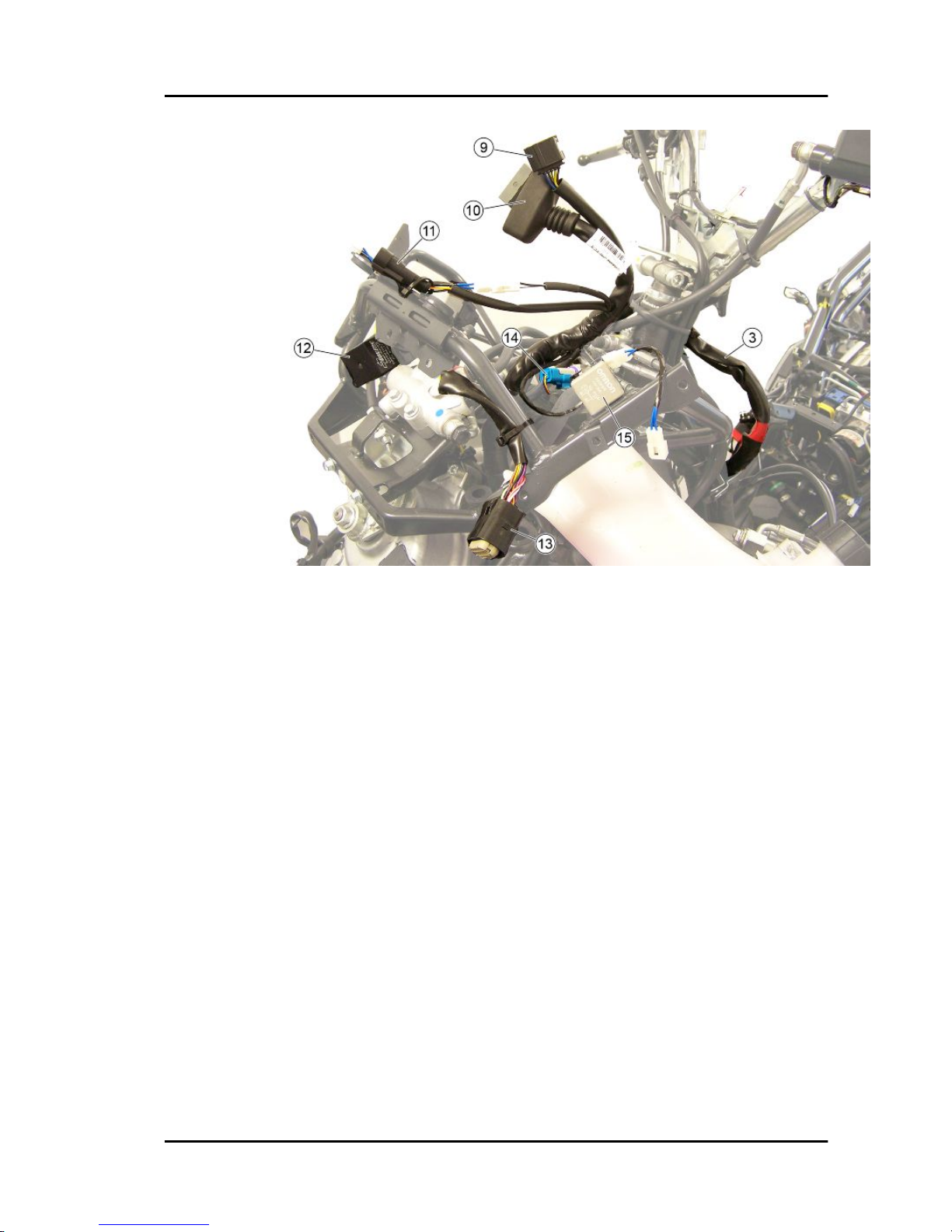
9. Warning light unit connector
10. Instrument panel connector
11. USB socket connector
12. Turn indicators control device
13. PMP connection
14. Pressure sensor
15. Stop light relay
MP3 500 i.e. SPORT Business_LT_ ABS-ASR_EU_USA (2015) Electrical
system
ELE SYS - 77
Page 78

16. Relay unit connections
17. Gear motor connector
18. Rotation sensor and headlamp wiring
Electrical system MP3 500 i.e. SPORT Business_LT_ ABS-ASR_EU_USA
(2015)
ELE SYS - 78
Page 79

19. Rotation sensor connector
20. Headlight connector
21. Rotation sensor
22. Front daylight running light connector
23. To electric fan
24. Pressure sensor connector
MP3 500 i.e. SPORT Business_LT_ ABS-ASR_EU_USA (2015) Electrical
system
ELE SYS - 79
Page 80

25. Saddle opening switch connector
26. ASR Button connector
27. Wheel sensors wiring
Electrical system MP3 500 i.e. SPORT Business_LT_ ABS-ASR_EU_USA
(2015)
ELE SYS - 80
Page 81

28. Parking control ECU connector
29. To horn
30. Speed sensors connectors
31. Secondary fuses
MP3 500 i.e. SPORT Business_LT_ ABS-ASR_EU_USA (2015) Electrical
system
ELE SYS - 81
Page 82

32. Front wiring branch
33. Speed sensor
34. Front ABS sensor
Electrical system MP3 500 i.e. SPORT Business_LT_ ABS-ASR_EU_USA
(2015)
ELE SYS - 82
Page 83

35. Front ABS sensors connectors
Back side
1. ABS control unit connector
MP3 500 i.e. SPORT Business_LT_ ABS-ASR_EU_USA (2015) Electrical
system
ELE SYS - 83
Page 84

2. Main cable harness
3. To ground point on chassis
4. Positive battery pole
5. Start-up relay connections
6. Main fuses
7. HV coil
Electrical system MP3 500 i.e. SPORT Business_LT_ ABS-ASR_EU_USA
(2015)
ELE SYS - 84
Page 85

8. Left taillight, license plate lights and saddle opening switch actuator wiring
9. Left taillight connector
10. Rear left turn indicator connector
MP3 500 i.e. SPORT Business_LT_ ABS-ASR_EU_USA (2015) Electrical
system
ELE SYS - 85
Page 86

11. License plate lights connector
12. Saddle opening actuator
13. Engine speed sensor connector
Electrical system MP3 500 i.e. SPORT Business_LT_ ABS-ASR_EU_USA
(2015)
ELE SYS - 86
Page 87

14. Rear ABS sensor connector
15. Starter motor positive
16. Injection ECU connector
17. Engine temperature sensor
18. Injector
19. Plug socket
20. Oxygen sensor connector
21. Pre-installation for anti-theft device
22. Horn connection for anti-theft device
23. Magneto flywheel connector
MP3 500 i.e. SPORT Business_LT_ ABS-ASR_EU_USA (2015) Electrical
system
ELE SYS - 87
Page 88

24. Helmet compartment light connector
25. Rear right turn indicator connector
26. Right taillight connector
27. Voltage regulator connector
Electrical system MP3 500 i.e. SPORT Business_LT_ ABS-ASR_EU_USA
(2015)
ELE SYS - 88
Page 89

28. To voltage regulator
Conceptual diagrams
MP3 500 i.e. SPORT Business_LT_ ABS-ASR_EU_USA (2015) Electrical
system
ELE SYS - 89
Page 90

Ignition
KEY
1. Instrument panel
13. Secondary fuses
31. Main fuses
32. Battery
35. Fuse No. 13
36. ignition key contacts
40. Injection load relay
53. Engine speed sensor
54. HV coil
55. Injector
57. Fuel pump
64. Injection ECU
65. Immobilizer aerial
Electrical system MP3 500 i.e. SPORT Business_LT_ ABS-ASR_EU_USA
(2015)
ELE SYS - 90
Page 91

Battery recharge and starting
KEY
11. Starter button
13. Secondary fuses
16. Stop buttons lever and brake pedals
22. engine stop switch
23. Stop light relay
29. Magneto flywheel
30. Voltage regulator
32. Battery
33. Start-up relay
34. Starter motor
35. Fuse No. 13
36. ignition key contacts
38. Rear headlight assembly
64. Injection ECU
66. Warning light unit
MP3 500 i.e. SPORT Business_LT_ ABS-ASR_EU_USA (2015) Electrical
system
ELE SYS - 91
Page 92

Level indicators and enable signals section
KEY
1. Instrument panel
2. Ambient temperature sensor
10. Fuel level transmitter
11. Starter button
12. Headlight relay
13. Secondary fuses
16. Stop buttons lever and brake pedals
22. engine stop switch
23. Stop light relay
24. Electric fan relay
31. Main fuses
32. Battery
33. Start-up relay
35. Fuse No. 13
36. ignition key contacts
40. Injection load relay
46. Parking control ECU
Electrical system MP3 500 i.e. SPORT Business_LT_ ABS-ASR_EU_USA
(2015)
ELE SYS - 92
Page 93

62. Tip over sensor
64. Injection ECU
66. Warning light unit
69. Oil pressure sensor
Devices and accessories
CAUTION
THE FOLLOWING INSTRUCTIONS REFER TO THE VEHICLE VERSION EQUIPPED WITH ABS ASR SYSTEM.
KEY
1. Instrument panel
3. Turn indicator bulbs
6. Turn indicators control device
7. Pre-installation for anti-theft device
8. Headlight
10. Fuel level transmitter
12. Headlight relay
13. Secondary fuses
14. ignition key contacts
15. USB socket
17. Ignition switch contacts
MP3 500 i.e. SPORT Business_LT_ ABS-ASR_EU_USA (2015) Electrical
system
ELE SYS - 93
Page 94

18. Saddle opening switch
19. Saddle opening actuator
20. Light switch
21. Pre-installation heated handgrips control device and leg warmer
26. Plug socket
27. Helmet compartment light switch
28. Helmet compartment light bulb
31. Main fuses
32. Battery
35. Fuse No. 13
36. ignition key contacts
39. Fuse No. 14
41. Pressure sensor
42. Horn relay
43. PMP connection
44. Geared motor
45. Brake calliper sensor
46. Parking control ECU
47. Right speed sensor
48. Left speed sensor
50. Rotation sensor
51. Hand brake switch
52. Suspension locking/unlocking switches
58. ABS control unit
59. Rear ABS sensor
60. Left front ABS sensor
61. Right front ABS sensor
63. Diagnostic socket
64. Injection ECU
66. Warning light unit
68. MODE button
70. Horn
71. horn button
72. Horn connection for anti-theft device
73. Rider presence sensor
CAUTION
THE FOLLOWING INSTRUCTIONS REFER TO THE VEHICLE VERSION NOT EQUIPPED WITH
ABS - ASR SYSTEM.
Electrical system MP3 500 i.e. SPORT Business_LT_ ABS-ASR_EU_USA
(2015)
ELE SYS - 94
Page 95

KEY
1. Instrument panel
3. Turn indicator bulbs
6. Turn indicators control device
7. Pre-installation for anti-theft device
8. Headlight
10. Fuel level transmitter
12. Headlight relay
13. Secondary fuses
14. ignition key contacts
15. USB socket
17. Ignition switch contacts
18. Saddle opening switch
19. Saddle opening actuator
20. Light switch
21. Pre-installation heated handgrips control device and leg warmer
26. Plug socket
27. Helmet compartment light switch
28. Helmet compartment light bulb
31. Main fuses
MP3 500 i.e. SPORT Business_LT_ ABS-ASR_EU_USA (2015) Electrical
system
ELE SYS - 95
Page 96

32. Battery
35. Fuse No. 13
36. ignition key contacts
41. Pressure sensor
42. Horn relay
43. PMP connection
44. Geared motor
45. Brake calliper sensor
46. Parking control ECU
47. Right speed sensor
48. Left speed sensor
50. Rotation sensor
51. Hand brake switch
52. Suspension locking/unlocking switches
63. Diagnostic socket
64. Injection ECU
66. Warning light unit
68. MODE button
70. Horn
71. horn button
72. Horn connection for anti-theft device
73. Rider presence sensor
Electrical system MP3 500 i.e. SPORT Business_LT_ ABS-ASR_EU_USA
(2015)
ELE SYS - 96
Page 97

Lights and turn indicators
KEY
1. Instrument panel
3. Turn indicator bulbs
4. Turn indicator switch
5. Emergency turn indicator switch
6. Turn indicators control device
8. Headlight
9. Front daylight running light bulb
12. Headlight relay
13. Secondary fuses
14. ignition key contacts
20. Light switch
31. Main fuses
32. Battery
35. Fuse No. 13
36. ignition key contacts
37. License plate bulbs
38. Rear headlight assembly
MP3 500 i.e. SPORT Business_LT_ ABS-ASR_EU_USA (2015) Electrical
system
ELE SYS - 97
Page 98

46. Parking control ECU
Checks and inspections
This section is dedicated to the checks on the electrical system components.
Immobiliser
The electronic ignition system is controlled by the
control unit with the integrated Immobilizer system. The immobilizer is an anti-theft system that
allows the operation of the vehicle only if it is started with the keys encoded and recognized by the
control unit. The code is integrated in a transponder in the key body. This allows transparent operation to the driver who does not have to carry out
any other operation than to normally turn the key.
The immobilizer system contains the following
components:
- an electronic control unit
- immobilizer aerial
- master key with built-in transponder
- service key with built-in transponder
- HV coil
- diagnosis LED
The diagnosis LED also works as a theft-deterrent
blinker. This function is activated every time the
ignition switch is set to «OFF» or the emergency
stop switch is set to «OFF». It remains activated
for 48 hours in order not to affect the battery
charge. When the ignition switch is turned to
«ON», the deterring blinker function is deactivated
and a flash confirms the switching to « ON». The
duration of the flash depends on the programming
of the electronic control unit. If the LED is off regardless of the position of the ignition switch and/
or the instrument panel is not initiated, check if:
•
there is battery voltage
Electrical system MP3 500 i.e. SPORT Business_LT_ ABS-ASR_EU_USA
(2015)
ELE SYS - 98
Page 99

•
fuses 2, 11, 13 are in working order
•
there is power to the control unit as
specified below
Remove the connector mounting bracket shown in
the photograph and disconnect the connector from
the control unit. Check the following conditions:
With the key switch set to OFF:
•
if there is battery voltage between terminals 7-26, 15-26 and terminal 26chassis ground (fixed power supply). If
there is no voltage, check that fuse 6
and its cable harness are in working
order.
With the key switch in the ON position:
•
if there is battery voltage between terminals 7-4, 15-4 and terminal 4-chassis ground (fixed power supply). If
there is no voltage, check the ignition
switch contacts and that fuses No. 10,
13 and their cables are in working order.
MP3 500 i.e. SPORT Business_LT_ ABS-ASR_EU_USA (2015) Electrical
system
ELE SYS - 99
Page 100

•
There is continuity between terminals
21-23 with the emergency cut-off
switch set to «RUN». If there is no continuity check the contacts of the switch.
After removing the leg shield back plate, remove
the electrical connection from the aerial as shown
in the picture.
Remove the protective base from the connector.
Electrical system MP3 500 i.e. SPORT Business_LT_ ABS-ASR_EU_USA
(2015)
ELE SYS - 100
 Loading...