

Page 1
D
Cl)
©
-‘
C
C-)
0
SD
D
©
D
C
c)
4
I
Page 2

Notes
A)
B)
C)
0)
on
Owing
the
of
user
the
avoid
continuously
area
When
changing
machine
from
maximum
The
light
the
drive
The
anyone
by
agent.
safety
to
needle
must
injury
leaving
the
the
and
parts
must
power
bulb
belt
but
and
up
and
take
observe
the
or
be
source.
approved
15
is
must
an
down
upper
the
sufficient
the
sewing.
while
machine,
accessories,
disconnected
wattage
watts.
be
never
authorized
movement
knife,
care
sewing
the
adjusted
Pfaff
to
of
Page 3
Contents
V
Parts
of
Electrical
Master
switch
Foot
control
Notes
on
Installing
Opening
Threading
Threading
Threading
Threading
Thread
reel
Inserting
Seam
allowance
Sewing
Points
test
to
Securing
Axial
blocking
Setting
the
Correcting
Thread
Setting
chart
the
Disengaging
Adjusting
Changing
Rolled
hems
Changing
Changing
Changing
Changing
Changing
Cleaning
Oiling
the
Sewing
problems
Accessories
Thread
spool
Specifications
Contents
the
sewing
connection
.
safety
the
thread
the
looper
guide
the
the
the
change
the
lint
observe
the
seam
standard
the
for
stitch
the
the
seam
the
sewing
the
needle
the
knives
the
upper
the
lower
the
light
the
thread
machine
net/thread
of
the
and
sewing
.
.
wires
right
left
looper
needle
box
during
of
the
thread
3-thread
length
upper
bulb
and
cardboard
machine
spool
cover
and
looper
on
threaded
upper
thread
tensions
knife
width
foot
knife
knife
. .
tensions
their
light
stand
.
the
sewing
knife
tensions
overedge
.
removal
unreeling
box
.
thread
machine
. .
.
disc
guides
seam
V
behind
the
carrying
.
V
V V
.
.
V
.
.
. .
handle
.
.
.
7
Page 4
Page 5
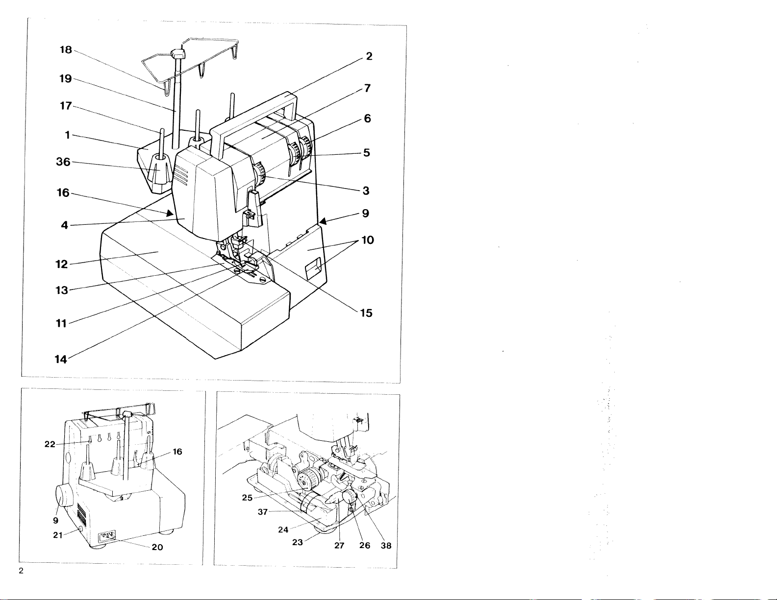
Parts
sewing
of
the
machine
Thread
Carrying
2
Needle
3
4
Housing
Right
5
Left
6
Thread
7
Lint
8
Handwheel
9
Looper
10
11
Upper
12
Work
13
Needle
Sewing
14
15
Needle
16
Sewing
Thread
17
Thread
18
Thread
19
Machine
20
Master
21
Rear
22
Feet
23
Accessory
24
Stitch
25
26
Seam
Rotary
27
disengagement
28
Foot
Foot
29
Mains
30
Right
31
Left
32
Lower
33
Lower
34
Retaining
35
Thread
36
37
Accessories
Retaining
38
upper
looper
looper
box
knife
support
thread
length
width
lever
control
control
plug
looper
looper
knife
knife
knife
spool
handle
thread
cover
tension
cover
plate
foot
bar
foot
spool
guides
guide
socket
switch
box
screw
spool
screw
stand
tension
thread
thread
cover
with
(swiveLtype)
lifting
holder
bar
guide
adjustment
adjustment
for
upper
plug
for
retaining
of
centering
retainer
for
tension
tension
recess
lever
x)
(4
machine
screw
upper
blocking
30
dial
dial
dial
28
knob
knob
knife
socket
knife
piece
31
the
32
.35
3.
Page 6
this
a
on
to
control
off
switched
are
the
it
and
switch.
switch
connection
machine
sewing
special
the
foot
of
plug
Then
socket
source.
power
a
the
When
the
off
at
plug
the
place
Do
not
machine
the
sewing
simultaneously
12
On:
Machine
on.
off:
again.
switched
only
the
machine
master
light
Machine
off.
on
table.
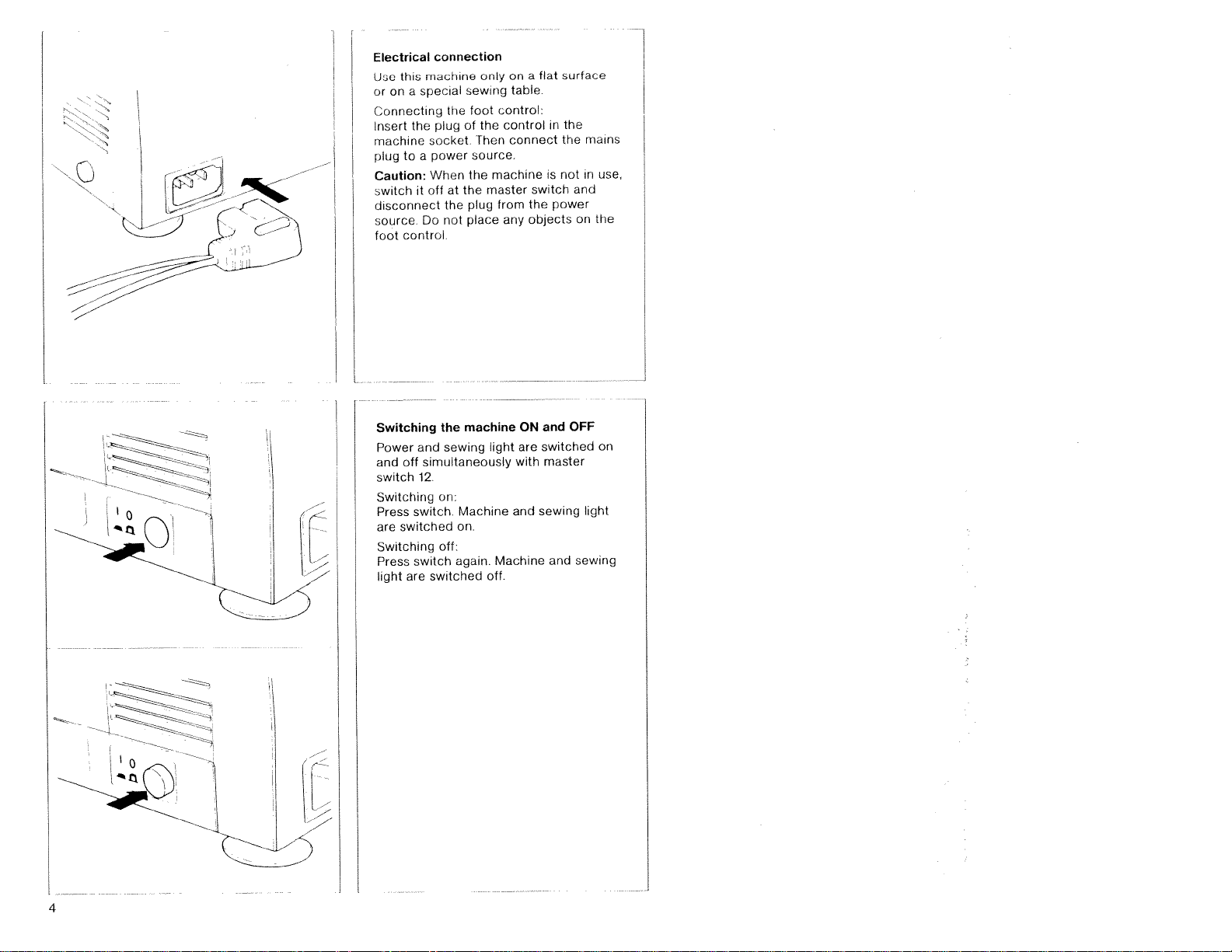
control:
control
connect
from
any
ON
are
with
and
fiat
a
is
switch
the
objects
and
switched
master
sewing
surface
in
the
the
not
power
and
in
and
on
OFF
tight
sewing
mains
use,
the
on
Electrical
Use
or
Connecting
Insert
machine
plug
Caution:
switch
disconnect
source
foot
Switching
Power
and
switch
Switching
0
Press
are
Switching
Press
tight
4
Page 7
control
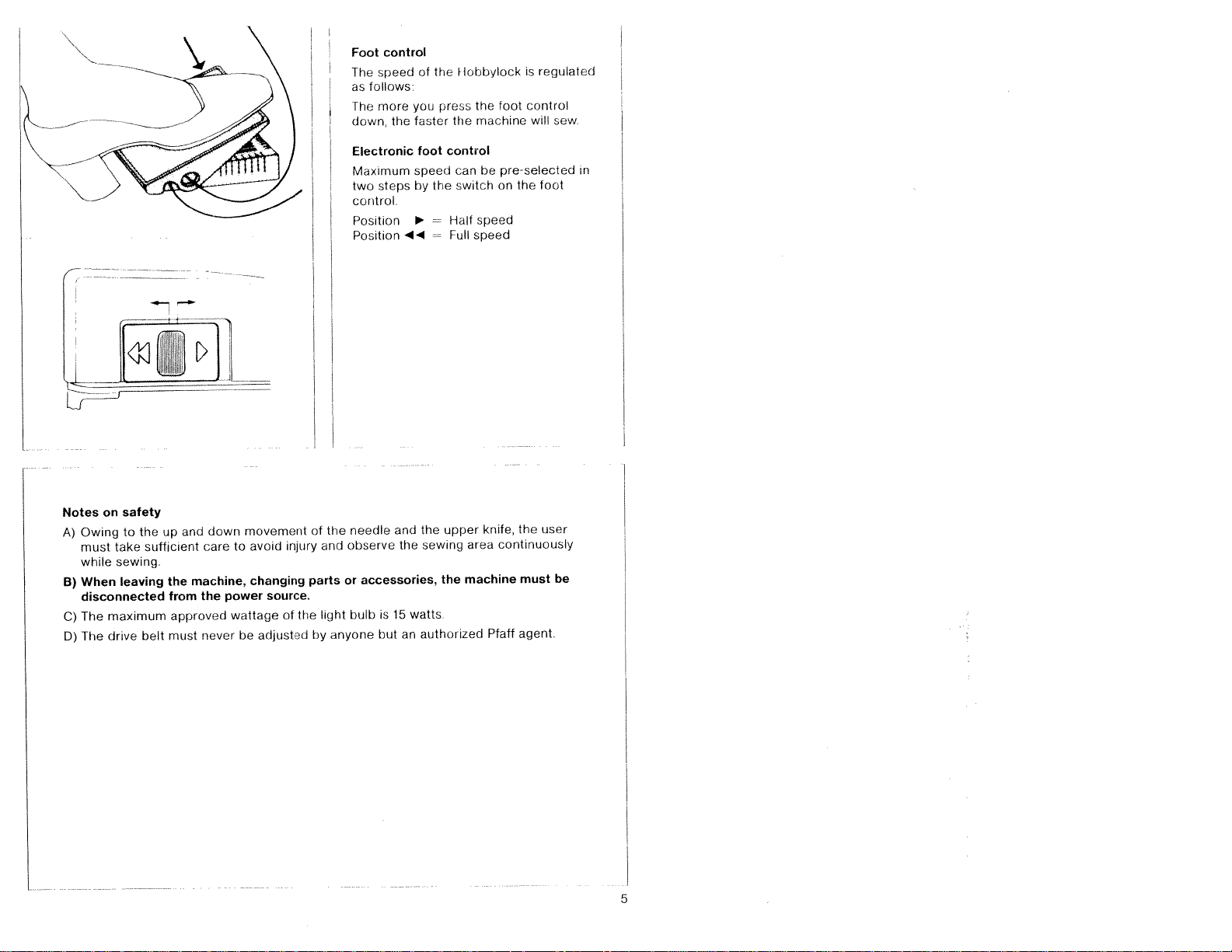
Foot
speed
The
follows
as
more
The
the
down,
Electronic
Maximum
steps
two
control
Position
Position
4
of
you
faster
toot
speed
by
the
press
control
the
[lobbylock
the
machine
the
be
can
switch
Half
speed
speed
Full
is
regulated
control
foot
will
pre-selected
foot
the
on
sew.
in
Notes
A)
Owing
must
while
When
B)
disconnected
The
C)
The
D)
safety
on
to
take
sewing.
leaving
maximum
drive
the
up
sufficient
belt
and
machine,
the
from
approved
must
down
care
the
never
to
power
wattage
be
movement
avoid
changing
source.
of
adjusted
injury
the
of
and
parts
light
by
the
or
anyone
needle
observe
accessories,
is 15
bulb
but
and
the
an
the
sewing
watts
authuiized
upper
the
knife,
area
machine
Pfaff
user
the
continuously
must
agent.
be
5
Page 8
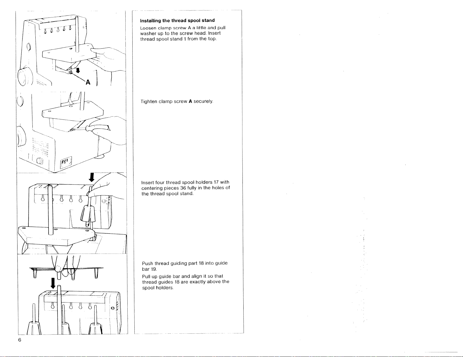
Installing
Loosen
washer
thread
clamp
up
spool
the
to
thread
screw
the
stand
screw
1
spool
A
a
from
little
head.
stand
the
and
Insert
top.
pull
Tighten
Insert
centering
thread
the
Push
19.
bar
Pull
up
thread
spool
clamp
four
thread
guide
guides
holders.
thread
pieces
spool
guiding
screw
bar
18
spool
36
stand.
and
are
securely
A
fully
part
align
exactly
holders
the
in
18
it
into
so
above
17
holes
guide
that
with
of
the
6
Page 9
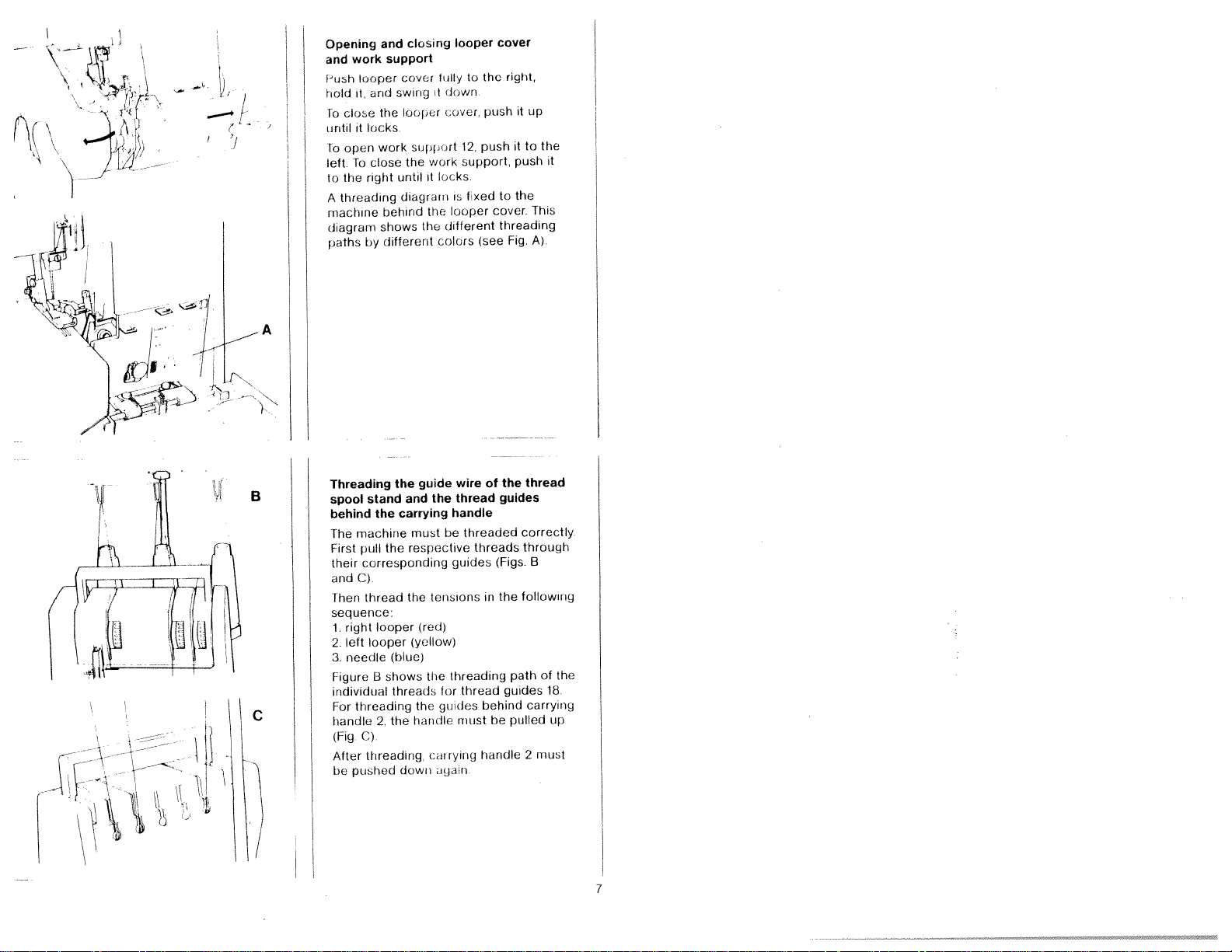
cover
it
support
work
it
the
the
looper
fullytothe
down
cover,
push
12.
support,
locks.
fixed
is
looper
different
(see
colors
push
to
cover
threading
right,
it
it
push
the
Fig.
up
to
the
it
This
A)
work
looper
and
it
close
locks
it
open
close
To
right
the
threading
by
and
support
cover
swing
looper
the
work
until
diagram
behind
shows
different
the
Opening
and
2
A
Push
hold
Fo
until
lo
left
to
A
machine
diagram
paths
closing
B
)
Threading
stand
spool
behind
machine
The
First
pull
corresponding
their
C)
and
thread
Fhen
sequence:
right
1.
left
2.
3.
needle
Figure
individual
threading
For
handle
C)
(Fig
Aftei
threading.
pushed
be
the
the
looper
looper
shows
H
2.
the
and
carrying
the
(blue)
threads
the
dowii
wireofthe
guide
thread
the
handle
mustbethreaded
respective
(red)
(yellow)
the
the
handle
guides
tensions
threading
for
guides
cm
rying
igdin
threads
in
thread
behind
must
handle
guides
(Figs
the
be
correctly
following
path
guides
pulled
thread
through
B
of
18
carrying
up
2
must
the
7
Page 10
Threading
thread
Band
1
to
thread
of
thread
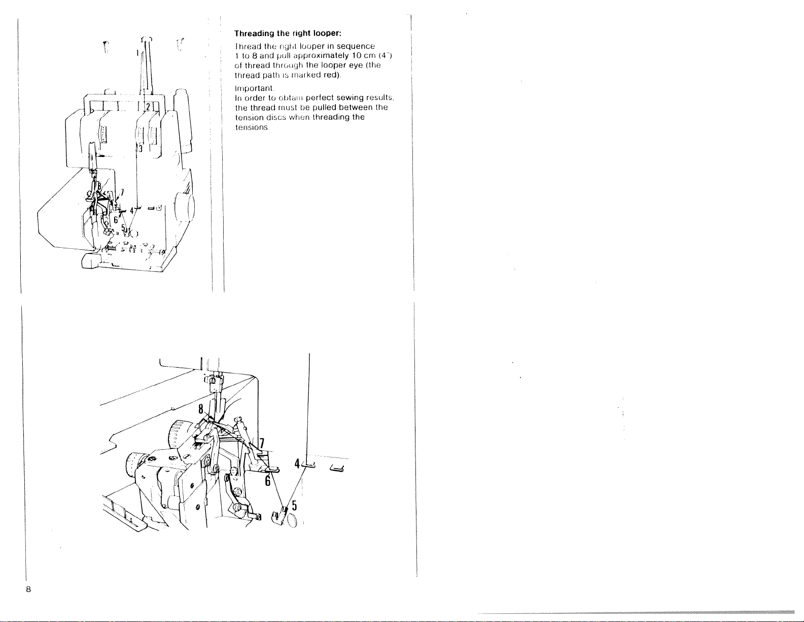
Important
order
In
thread
the
tension
nsmns
te
right
the
the
rtt
tiull
through
murked
path
s
obtdln
to
mustbepulled
disco
when
looper:
looper
in
opproximately
looper
the
red)
perfect
threading the
sequence
10
eye
sewing
between
cm
(the
results
(4)
the
8
Page 11

I
Threading
1
Insert
to
1
thread
of
thread
the
yellow)
sequence
in
10
eye
cm
(the
(4
the
and
9
path
pull
through
is
approximately
looper
the
marked
thread
looper
left
looper:
left
9
Page 12

Threading
Threadingofguide
thread
is
shown
In
the
pathisshoiiri
up
thread
retainer
the
guide
on
hand
left
to
the
right
mustbepulled
needle
behind
page
from
needle
wires18and
the
7
illustration
the
blue
(6).Atpoint5the
behind
carrying
the
tension
of
the
handle
threading
the
thread
(1)
Thread
Cut
the
Tie
the
threads
outofthe
last
thread
respective
interruption
spool
threads
needle.
needle
change
guide
Pull
on
closetothe
stillinthe
Now
pullatthe
before
eyes.
about
10
threaded
thread
machine
the
needles.
looper
The
cmofthread
machine
spool.
and
thread
Cut
threads
Place
the
new
ends
the
through
threads
until
knots
can be
the
new
After
down,
2
looper
thread
the
off
pulled
looper
threading
together
knots
and
until
and
cover
spools
pull
eye
the
close
10
Pull
are
about15cm
the
threads
past
machine, push handle
work
support
on
spool
holders
the
needle thread
past
through
the
looper
eyes
12
and
17.
the
the
without
Page 13

Inserting
Insert
downwards
_\
cover
against
For
reverse
removal
the
Then
the
the
two
order
lint
tubs
in
the
push
machine
of
the
box:
of
recess
the
lint
the
bottom
box,
lint
of
the
use
box
of
looper
the
the
box
/
/
Seam
allowance
If
the
cutting
marking
allowance
consideration
guided
is
on
N
the
of
16
when
looper
mm
along
must
cutting
cover,
be
below
taken
the
a
seam
fabric.
into
11
Page 14

Sewing
After
he
Raise
the
test
threadingasewing
made
sewing
illustration
foot
lever
16,
test
as
test
shown
should
in
5thN
.1
Insert
test
and
lower the
Hold
thread
while
turning hand wheel
hand
arrowonthe
back under
that
the
in
threads
fabricupto
sewing
with
ends
direction
wheel.
the
sewing
have
interlocked
the
foot.
your
indicated
Lay
the
foot.
upper
with
left
your
threads
Make
correctly.
hand
by
knife
right
the
sure
Page 15

Points
Place
sewing
after
Sew
Since
not
hand
Sew
of
the
the
pull
observe
to
fabric
the
when
foot
machine
the
stitches
first
the
fdbricisfed
the
push
or
guiding
for
approxirriately
thread
seam
and
chain.
during
completely
starting
has
been
slowly
automatically,
fabric
the
only
cm
5
a
use
sewing
under
to
rethreaded)
Use
beyond
scissors
sew
your
to
the
(Also
the
cut
do
end
13
Page 16

Securing
Knot
a
crochet
thread
Or:
about5cm
Sew
scam
and
sew
sewn
just
chain
the
chain
Then
the
thread
needle
few
a
without
into
turn
seam:
stitches
chdin
can
the
(2
the
cutting
be
eani
beyoi
work
For
ovei
knit
ued
piece
the
d
to
the
the
thread
fabrics,
pull
end
around
seam
the
knife
upper
very
different
this
or
be
the
thick
machine,
thin
Plheni
wonkpieces
the
tightened,
fabrics
thicknesses:
kinds
all
extremely
to
sewing
screw
as
workpieces
and
of
fabric
thick
extremely
different
with
the
of
upper
showninthe
can
from
be
thick
knife
Blocking
Sewing
with
On
extremely
processed
of
fabrics
thicknesses
must
illustration
tightening
By
the
of
upper
ft
knife
ie
screw,
is
inhibited
axial
movement
Note:
that
must
the
be
the
When
screw
loosened
upper
sewing
the
of
by
knife
medium
or
thin
knife
upper
about2turns,
move
can
fabrics,
holder
so
axially.
14
Page 17

thread
fabric
7
the
16
the
N
(see
(the
lists
standard
tension
on
the
correct
seam)
type
and
thread
the
edgeofthread
front
Hustration
adjustment
of
the
Hustrator
examples
thread
thread
tobeset
thread
tension
below>
interlocking
on
the
for
correction
tensions
tension
depends
size
dials
after
of
left
N
used
tension
shows
of
Setting
Heverse
Left
0
/
;
i/
.1
//
;;1
/
t
i
Iou
thread
Right
looper
thread
Needle
Top
per
side
side
The
on
the
the
Set
opposite
cover
Make
examination
threads
a
correct
Page
individual
the
i•’
Wj\
Page 18

Feerse
k)J
0
C
side
side
Correcting
When
(+)
direction
When
decreased
The
needle
(blue
The
right
(red
thread
thread
tension>.
the
turned
thread
D
too
the
thread
thread
looper
tension)
thread
the
iii
(
tcniori)
thread
tight
tension
tension
direction
>
A
or
(yellow
tensions
is
too
Cistoo
the
is
turned
is
increased
loose
left
thread
it
is
looper
in
loose
The
left
looper
thread
0
is
too
(yellow
looper
thread
thread
tension)
too
C
tight
loose
or
the
right
(red
thread
tension>.
D
C
Page 19

Material
Light
materials
Organdy,
fabric,
Taffeta,
lining
materials
Medium-heavy
materials.
Cotton,
linen,
Heavy
Tweed,
denim,
Knit
Rolled
tricot,
dress
materials:
suit
heavy
fabrics:
hem
light-knit
silk,
materials
materials,
cloth
Thread
chart
Cotton
Silk
Synthetic
Cotton
Silk
Synthete
Cotton
Silk
Synthetic
Cotton
Silk
Synthetic
Polyester
Mercerized
(bulk
thread)
for
3-thread
thread
thread
thread
ttiread
thread
thread
hread
overedge
No
No
No.
No
No
No.
No.
No.
No
No.
No.
No.
No.
80-
1
80-100
70—
140
60--lOU
50-100
70—140
40—60
40-60
70—140
40-60
40-60
70—140
120—140
(JO
seam
2.0
20
2.0
2.0
1.0
Stitch
to
to
to
to
to
5.0
20mm
length
4
40
50
0
mm
mm
mm
mm
Setting
Open
fast
and
knob
between
is
3
mm.
work
25
the
set
at
1
arid
stitch
support
the
length
12.
stitch-length
stitch
5
mm
Hold
adjustment
length
Standard
hand
desired
setting
wheel
9
N
17
Page 20

L
1
kf[J)
\
N,
Disengaging
Remove
arid
looper
loosen
screw
hi
ock
ng
Push
rotary
knife
guide
turn
forwards
it
the
hole
knife
disengiged
is
lint
nf
the
bn
cover
lenr
full,’
the
‘38
until
knife
upper
Open
8
10
If
for
axial
27ofthe
to
the
pin
Now
knife
work
necessary,
upper
axial
rrght,
hold
engages
A
the
support
knife
upper
it,
upper
12
and
in
A
2
(
Adjusting
The
standard
marked
Disengage
the
above
The
desired
adjusting
width
to
3
5.
Set
the
again
When
tighten
knife,
Sew
a
Note,
Atler
adjusting
be
necessary
tension.
the
with
the
description
seam
knob
adjustment
upper
and
close
processing
screw
see
page
test
sewn
scorn
N
knife
38
to
seam
(3
upper
2b
the
14
the
re
5
width
The
knob
thick
for
seam
width
width
mm).
knife
at
its
looper
blocking
aillust
setting
is
scale
ranges
basic
fabrics,
width,
the
according
set
with
on
the
from
position
cover.
securely
the
it
thread
is
to
seam
upper
may
Page 21

Changing
Raise
Disengage
ever
sewing
F
the
the
sewing
fuot
sewing
lifting
foot
foot
ever
by
1
16
pressing
F
G
Engage
Place
foot
sewing
of
the
sewing
The
illustration
correctly
the
holder
foot
foot
foot
the
sewing
sewing
so
lifting
engages
holder
engaged
on
that
foot.
foot
when
lever
in
the
sewing
under
crosspjece
groove
left
you
shows
foot.
the
lower
H
sewing
of
a
the
G
the
19
Page 22

lop
101)
side
side
Reverse
Reverse
side
side
Rolled
sewn
A
roWed
fabrics
open
sew
scarves
(see
hem
with
polyester
hem
and
is
edges
professioriat
shawL,
page
21)
is
used
an
uttractive
Witfiout
rolled
and
thread
for
light
any
hems
valances
120--140
finish
effort
delicate
for
you
on
neck
cdn
Page 23

Rolled
hem
with
polyester
thread
Preparation
I
Jcedk
Sewing
Seam
width,
Stitch
length:
Thread:
Threading
right
I
left
looper,
2
3
needle
For
ttireading
Tension
Red
thread
Yellow
Blue
thread
3epending
Rolled
bern
This
Preparation
Thread:
of
engage
foot.
from10
polyester
path:
looper, red
yellow
thread,
of
setting:
tension,
thread
tension,
on
hem,
sewn
requires
of
thread--red
bulk
polyester
the
insert
from
blue
needle
tension
material
the
sewing
needle
rulkit
30
patti
putt
right
needle
with
three
machine,
thread
to4Ii
to
20
threud
pat
1
rind
looper
loft
and
bulk
threads,
tension
120
machine:
tern
mm
(short
120
loopers,
limper
thread
thread,
thread:
as
140
tout
(depending
stitch
-140
see
the
one
descnit,ed
for
‘‘0
length)
for
pages1to
round
upprox.
appi
respective
bulk
tilne
blue
thread
above
id
ai
on
ox
matenal)
red
edge,
“N”
+
5
“N”
thread
and
yellow
and
11
Fig.
two
tensions
yellow
polyester
polyester
polyester
1
tension
polyester
threud
tensions
thread
tire
t
ad
thread
flat
edge,
approx
approx
upprox
mustbeset
threads
+ 5
“N”
“N”
Fig.
to—1
to+1
higher
120—
2
140
or
lower.
Threading
1
rigfrt
left
2.
needle
3
threading
For
Tension
Red
thread
Yellow
thread
Blue
Note:
Rolled
bulk
The
Depending
lower.
lonper,
looper,
setting:
thread
hems
threads
path:
thread,
tension,
tension,
can
on
red
yellow
of
needle
tension,
also
must
mateiial
putt
patti
blue
path
and
right
looper
left
needle
be
sewn
Uteribethreaded
and
loopers,
looper
thread
thread,
with
see
two
the
pages7to
round
edge,
appnox
appiox.
upirox.
bulk
threads
ri
the
respective
left
“N”
-t
“N”
5
and
thread
thread
bulk
polyester thread
polyester
ii.
Fig.
1
3
to
and one
right
polyester
looper
tension
ttrread
flat
dpfiroX
approx
upprox.
must be
120—140
120—140
edge,
thread
“N”
“N”
“N”
set
Fig.
to
higher
2
4
5
or
21
Page 24

Changing
Pull
out
sewing
direction
bar
is
needle
(see
needle
tool
with
the
by
pulling
the
toot
at
change
31.
p
in
Loosen
screw
the
ii
[urn
of
the
its
highest
tern
hole
tnic
it
downwards.
needle
ii.
arrow
tool
llj
M
of
set
driver
plug
the
position
from
as
the
screw
Lower
hand
until
the
follows:
needle
Remove
the
wheel
the
needle
Use
accessories
Insert
change
of
the
the
in
the
the
needle
needle
the
(
Inserting
Insert
change
of
the
the
needle
needle
as
it
will
Tighten
Remove
needle
Notes:
ihe
following
machines.
System
Although
on
the
used,
An
incorrectly
cause
s
ti
let
res.
Changing
Knives
Pull
out
Disengage
the
tool
needle
up
go
needle
needle
130/705
the
material
we
recommend
thread
the
are
the
the
needle
needle
in
such
shank
change
info
the
needles
correct
and
inserted
breakage
knives
avuilulile
mains
the
upper
in
set
change
H
plug.
hole
a
faces
tool.
needle
screw
(75-
needle
the
needle
as
knife,
way
Then
tool
are
90)
thread
needle
and
spare
M
of
that
surface
push
holder
securely.
from
used
size
size
will
skipped
parts
see
page
the
flat
on
depends
size
needle
side
L
the
as
the
these
75
K
of
far
90
18
Page 25

1;
c
I
I
/
Changing
Pull
Unscrew
rerr1cje
Insert
its
retaining
out
the
the
knife
upper
new
the
mains
screw
upper
rctdriring
knife
upper
knife:
plug.
knife
Securely
screw
and
35
tighten
arid
Set
upper
knife
with
knife
guide
27
lowest
of
mm
up
the
below
1
I
(cutting
until
position
In
upper
the
this
needle
the
position
knife
position)
upper
must
plate
Turn
knife
the
be
surface.
is
front
0.5
at
the
its
edge
to
handwheel
1
/
23
Page 26

Changing
Pull
Disengage
Remove retaining
knfe
Place
guide
it
up,asshown
Replace
plate.
out the
the
of
the
the
the
mains
the
new
lower
screw
lower
upper
lower
in
knife
plug!
screw
knife
knife
the
with
knife
(see
34
of
against
holder
illustration.
the
pressure
the
and
page
the
18)
lower
left
push
Align
the
cutting
edge
of
the
lower
so
that
itisflush
surface
Before
tightening
align
the
upper
knife
24
pressure
to
with
the
cutting
plate.
the
needle
retaining
Reset
position
knife
plate
screw,
the
Page 27

)
Changing
Pull
ousen
screw
)
/
Open
Behind
light
out
4
the
is
the
the
housing
hoicei
it,
the
situated
hght
mains
lijhl
g
plug.
cer
cover
bulb
bulb:
retaining
of
the
sewing
H
Removing
I
‘
/
(
Push
fully
Inserting
Insert
the
it
fully
Close
Cleaning
Pull
hands
and
Use
the
accessories
from
Replace
engageing
retainers
the
to
the
the
pins
to
and
thread
to
remove
brush
between
the
A
light
the
new
in
the
the
the
the
of
the
left
light
the
right
fasten
thread
tension
front
it
provided
to
remove
the
thread
tubs
the
light
bulb
bulb
slots,
housing
tensions.
housing
bulb:
upwards
bulb:
(15
Watt
push
tensions:
cover
(direction
with
dust
tension
of
the
it
cover.
7
with
and
cover
cover
up
of
the
and
max.)
arrow)
in
and
both
lint
by
turn
it
with
turn
25
Page 28

Oiling
the
machine:
F
very
rio
oil
and
rriade
oiled
two
oil
operation
to
the
other
of
only
drops
are
time
before
places
important
special
once
of
sufficient
high
you
Jou
should
indicated.
material
or
twice
quality
for
oiling.
take
moving
apply
The
and
a
month.
sewing
the
parts
need
machine
a
little
bushings
are
to
One
machine
be
to
26
Page 29

iese
made
e
peratiori
machines
Sewing
errors
have
problems
Ihey
been
can
of
easily
veliped
ftc
be
tind
corrected
for
easy
described
operation.
by
follnwing
below
and
may
the
there
ucr;ur
rnstruchoi
etc
(1(10
tO
10
.
difhcult
minOr
below.
adlustments
adjust
rnent
fri
and
Needle
Thread
Skipped
Prohlerri
breakage
breakage
stitches
F
teedle
ni
Intl
lUL(Jk(
F
Metered
Ii
icnr
tread
1
1
fired
Needle
Incur
Needle
damn
aged
Needle
Incorrect
Incur
redly
reef
redly
bet
damaged
riot
pulled
has
tension
not
needle
bent
not
needle
it
fully
threaded
caught
fully
or
pond
fully
threaded
ii
iSe
too
inserted
used
inset
used
led
fight.
led
Insert
Insert
(see
Do
sew
Thread
(see
Check
the
at
Regulate
(pages
Insert
use
Insert
Insert
Use
Thread
new
page
riot
i
rig
pages
reel
needle
needle
new
needle
needle
new
pull
correctly
whether
tension,
15,
needle
cnr
r
SO
i
cedle
needle
22)
n
aterial
7—10)
stamrd,
16)
correctly
system
correctly
system
ectly
it)
(01
thread
etc.
(pageS
fl
correctly
during
catches
(page
130/705
(page
130/705
22>
H
221
H
7—10).
Incorrect
formation
Puckered
stitch
seams
Incorrect
tensto
Thread
Incorrect
differential
hreid
1
incur
reef
setting
rs.
tension
setting
has
threading
teed.
caught
too
of
thread
tight
of
doe
In
Set
thread
(pages
Reduce
cially
(pages
Re-adjust
Thread
15,
thread
for
15,
correctly
tensions
16)
light
materials)
161
differential
tension
pages
correctly
(espe
feed.
7—
10>
27
Page 30

60
zz
77
2
3
8
H
)Y’i’
11
(115i]
Accessories
I
Screwcii
2
Screwdriver
3
nt
4
Tweezer,
5
Upper
6
Thread
7
Needles
8
Sewing
9
Rolled
10
Thread
11
Needle
bru
vol
h
kniif
uereehng
rTldchine
hem
spool
change
(big)
(small)
sewing
net
disc
oil
foot
tool
Thread
Very
tend
clown
Thread
Fhe
item
smaller
Remove
from
Put
pin
on
facing
28
the
and
top
useful
to
(Fig.
thread
6
of
the
of
down,
spool
for
become
A)
unreeling
unreeling
the
thread
thread
thread
thread
place
it,
with
net
synthetic
loose
disc
accessories
spools.
spool
reel
spool
the
thread
rounded-off
as
shown
unravel
disc
centering
pin.
on
the
in
threads
shown
is
used
thread
unreeling
section
Fig.
B
and
piece
Which
slip
as
for
36
reel
disc
C
Page 31

Specifications;
Maximum
Seam
width
Stitch
length
Sewing
I
Sewing
Needle
Number
foot
uhricatuori
foot
system
of
Dimensions
Weight
‘ewing
height
threads
speed
.
1300
1
3
ches’inin
mn
5
15inn
Hinged
Manual
5
mm
130/705
1
(rio
75
-
no.
90)
4
.
.
315x280
approx
x
330
80
mm
kg
Contents
1
umiachune
1
foot
1
instruction
lint
1
1
thread
4
thread
1
thread
1
machine
of
control
box
spool
spool
guide
cardboard
with
motor
manual/gu000ltee
stand
stand
cover
box
certificate
bars
29
Page 32

 Loading...