

Page 1

3117
Instruction Manual
296-12-17 545
Betriebsanl. engl. 11.96
Page 2

At the time of printing, all information and illustrations contained in this document were up
to date.
Subject to alteration
The reprinting, copying or translation of PFAFF Instruction Manuals, whether in whole or in
part, is only permitted with our previous permission and with written reference to the
source.
G.M. PFAFF AG
Postfach 3020
D - 67653 Kaiserslautern
Editing / Illustration
HAAS - Publikationen GmbH
D - 53840 Troisdorf
Page 3

Contents
Contents ...................................................... Chapter - Page
1 Safety .......................................................................1 - 1
1.01 Directives............................................................................... 1 - 1
1.02 General notes on safety ......................................................... 1 - 1
1.03 Safety symbols ......................................................................1 - 1
1.04 Built in safety systems .......................................................... 1 - 2
1.05 Important points for the user .................................................1 - 2
1.06 Operating and specialist personnel ....................................... 1 - 3
1.06.01 Operating personnel .............................................................. 1 - 3
1.06.02 Specialist personnel .............................................................. 1 - 4
1.07 Danger ................................................................................... 1 - 4
2 Proper use ................................................................ 2 - 1
3 Specifications ............................................................ 3- 1
4 Disposal of the machine ............................................. 4- 1
5 Notes on testing in accordance with EN 60204-1 ............ 5- 1
6 Transport, packaging and storage ............................... 6- 1
6.01 Transport to the customer’s premises................................... 6 - 1
6.02 Transport within the customer’s premises............................ 6 - 1
6.03 Disposal of the packaging ..................................................... 6 - 1
6.04 Storage ................................................................................... 6 - 1
7 Explanation of the symbols ......................................... 7 - 1
8 Operational controls............................................................... 8 - 1
8.01 On/Off switch......................................................................... 8 - 1
8.02 Stop button ............................................................................ 8 - 1
8.03 Functions of the pedal ........................................................... 8 - 2
8.04 Button for stopping knife actuation ....................................... 8 - 2
8.05 Functions of the quick control panel ..................................... 8 - 3
8.05.01 Functions of the switches and buttons ................................. 8 - 3
8.05.02 Switching the countdown device on/off................................ 8 - 4
8.05.03 List of parameters .................................................................. 8 - 5
8.05.04 Fault indication in the display ................................................ 8 - 6
9 Mounting and initial operation .................................... 9- 1
9.01 Mounting................................................................................ 9 - 1
9.02 Initial operation ...................................................................... 9 - 2
10 Switching the machine on/off .................................... 10 - 1
10.01 On/Off switch....................................................................... 10 - 1
11 Preparation ............................................................. 11 - 1
11.01 Inserting the needle............................................................. 11 - 1
Page 4

Contents
Contents ...................................................... Chapter - Page
11.02 Winding the bobbin thread, adjusting the thread tension... 1 1 - 2
11.03 Adjusting the needle thread tension
on purl buttonholes and flat bartacks ................................... 11 - 3
11.04 Threading the bobbin case, adjusting the thread
tension on purl buttonholes ................................................. 11 - 4
11.05 Adjusting the needle thread tension
on flat buttonholes and flat bartacks.................................... 11 - 5
11.06 Threading the bobbin case, adjusting the
thread tension on flat buttonholes ....................................... 11 - 6
11.07 Threading the needle thread ................................................ 11 - 7
11.08 Inserting the bobbin case ....................................................1 1 - 8
11.09 Adjusting the sewing pressure ............................................ 11 - 8
11.10 Adjusting the seam width .................................................... 11 - 9
11.11 Adjusting the left purl seam position ................................... 11 - 9
11.12 Adjusting the right purl seam position ................................1 1 - 1 0
11.13 Adjusting the backtack width ..............................................1 1 - 1 0
11.14 Adjusting the buttonhole width ...........................................1 1 - 11
11.15 Adjusting the number of stitches per buttonhole ................ 11 -12
11.16 Changing the knife ............................................................... 11 - 12
11.17 Changing the plastic insert in the needle plate ...................1 1 -1 3
11.18 Changing the work clamp.................................................... 11 -13
12 Sewing ................................................................... 12 - 1
12.01 Test seam ............................................................................1 2 - 1
12.02 Sewing with a single cycle .................................................. 12 - 1
12.03 Sewing with a double cycle................................................. 12 - 2
12.04 Stopping the machine in an emergency.............................. 12 - 2
13 Care and maintenance .............................................. 13 - 1
13.01 Cleaning............................................................................... 13 - 1
13.02 Lubricating ........................................................................... 13 - 2
13.02.01 General lubrication............................................................... 13 - 2
13.02.02 Lubricating the hook ............................................................ 13 - 3
13.03 Checking the air pressure.................................................... 13 - 4
14 Adjustment ............................................................. 14 - 1
14.01 Tools, gauges and other accessories ..................................14 - 1
14.02 Machine positions and needle bar positions ....................... 14 - 2
14.03 Engaging/disengaging the stop motion device ...................1 4 - 3
14.04 Toothed belt drives ..............................................................1 4 - 4
14.05 Basic position of the milled screws on the feed regulator.. 14 - 5
14.06 Needle bar and needle ........................................................1 4 - 6
14.06.01 Pre-adjusting the needle bar height ..................................... 14 - 6
14.06.02 Needle bar in its final position ............................................. 14 - 7
14.06.03 Needle bar pendulum .......................................................... 14 - 8
14.06.04 Needle plate to needle ........................................................ 14 - 9
14.06.05 Basic position of the needle bar .......................................... 14 -1 0
Page 5

Contents
Contents ...................................................... Chapter - Page
14.06.06 Lateral movement of the needle .........................................1 4 -11
14.07 Seam construction ............................................................... 14 - 12
14.07.01 Left purl seam...................................................................... 14 -1 2
14.07.02 Right purl seam.................................................................... 14 - 1 3
14.07.03 Bartack ................................................................................. 14 - 1 4
14.07.04 Description of seam construction ........................................ 14 - 1 5
14.07.05 Faults in the seam construction ........................................... 14 -16
14.08 Stop motion buffer............................................................... 14 -1 7
14.09 Adjusting the catches .......................................................... 14 - 18
14.10 Sensing lever and catch lever.............................................. 14 - 1 9
14.11 Work clamp.......................................................................... 14 -20
14.11.01 Basic position of the work clamp ........................................ 14 -2 0
14.11.02 Longitudinal positioning and parallelism of the work clamp 14 -2 1
14.12 Knife unit .............................................................................. 14 - 22
14.12.01 Cutting pressure................................................................... 14 - 22
14.12.02 Upper knife-arm-stop ........................................................... 14 -23
14.12.03 Lower stop motion buffer .................................................... 14 -24
14.12.04 Stop axle............................................................................... 14 -25
14.12.05 Locking lever ........................................................................ 14 - 28
14.12.06 Knife bar height .................................................................... 14 -29
14.12.07 Position of the knife carrier relative to the cutting slot ........ 14 - 30
14.12.08 Longitudinal position of the knife carrier .............................. 14 -31
14.12.09 Height with the buttonhole cutter........................................ 14 -32
14.12.10 Height with the buttonhole punch........................................ 14 - 33
14.12.11 Securing the knife ................................................................ 14 -34
14.12.12 Stopping the knife on the double cycle ................................ 14 -35
14.13 Engaging lever ...................................................................... 14 -36
14.14 Needle thread tension .......................................................... 14 -37
14.15 Bobbin thread trimmer ......................................................... 14 -39
14.16 Bobbin thread trimmer drive linkage .................................... 14 -40
14.17 Positioner.............................................................................. 14 -41
14.18 Presser roller and presser bar lifter with work clamp .......... 14 -42
14.19 Feed lifting cylinder .............................................................. 14 -43
14.20 Needle thread scissor........................................................... 14 -45
14.20.01 Function check ..................................................................... 14 -45
14.20.02 Height and longitudinal positioning ....................................... 14 -46
14.20.03 Trip guide.............................................................................. 14 -47
14.20.04 Stop piece ............................................................................ 14 - 48
14.20.05 Triggering the needle thread scissors .................................. 14 - 49
14.20.06 Backwards motion of the needle thread scissors ................ 14 -50
14.21 Hook and needle bar............................................................. 14 -51
14.21.01 Needle bar rise and clearance .............................................. 14 - 51
14.21.02 Needle bar height and needle guard..................................... 14 -52
14.21.03 Hook lubrication.................................................................... 14 -53
14.22 Bobbin case holder ............................................................... 14 -54
14.23 Needle thread monitor ......................................................... 14 -55
14.24 Thread tension and thread control........................................ 14 -56
Page 6

Contents
Contents ...................................................... Chapter - Page
14.25 Needle thread puller ............................................................ 14 - 57
14.26 Knife triggering time ............................................................ 14 - 5 8
14.27 Reducing speed................................................................... 14 -59
14.28 Switch off time..................................................................... 14 -60
14.29 Bobbin winder...................................................................... 14 - 61
14.30 Lubricating the feed regulator eccentric.............................. 14 - 6 2
14.31 Electrical switch ................................................................... 14 - 63
14.31.01 Switch for the starting mechanism (S2)............................... 14 -63
14.31.02 Switch for the work clamp (S3)............................................ 14 -6 4
14.31.03 Switch for machine stop (S5)............................................... 14 -65
14.31.04 Switch for monitoring control cam (S8) ............................... 1 4 -66
14.31.05 Switch for monitoring knife (S21) ........................................ 1 4 -67
14.32 Needle bar stroke ................................................................ 14 - 6 8
Page 7

Safety
1 - 1
1 Safety
1.01 Directives
The PFAFF 3117 was built in accordance with the following European regulations:
● EC Machine Directive ( 89/392/EEC, 91/368/EEC, 93/44/EEC, 93/68/EEC )
● Safety of Appliances Law, Machine Ordinance - 9GSGV
● EC Directive „Electromagnetic Compatibility“ ( 89/336/EEC, 92/31/EEC, 93/68/EEC )
● EN 60204-1 Safety of Machines, Electrical Equipping of Industrial Machines: Part 3
● EN 292 Parts 1 and 2: 1991 Safety of Machines ( Basic Terms )
● EN 294 Safety of Machines; safety clearance margins for avoiding dangerous situations
for the upper limbs
● EN 349 Safety of Machines; minimum safety clearances for avoiding the crushing of
bodily parts
● EN 418 Safety of Machines; EMERGENCY STOP devices
● DIN 45635 Measurement of noise levels
In addition to this Instruction Manual, observe also all generally accepted, statutory and
other regulations and legal requirements - also those of the country in which the machine
will be operating - and all valid environmental protection regulations!
The regionally valid regulations of the social insurance society for occupational accidents or
other supervisory organisations are to be strictly adhered to!
1.02 General notes on safety
● This machine may only be operated by adequately trained operators and only after
having completely read and understood the Instruction Manual!
● All Notes on Safety and Instruction Manuals of the motor manufacturer are to be read
before operating the machine!
● The Danger and Safety Instructions on the machine itself are to be followed!
● This machine may only be used for the purpose for which it is intended and may not be
operated without its safety devices. All Safety Regulations relevant to its operation are
to be adhered to.
● When exchanging sewing tools (e.g. needle, presser foot, needle plate, feed dog or
bobbin), when threading the machine, when leaving the machine unattended and during
maintenance work, the machine is to be separated from the power supply by switching
off the On/Off switch or by removing the plug from the mains!
● Everyday maintenance work is only to be carried out by appropriately trained personnel!
● Repairs and special maintenance work may only be carried out by qualified service staff
or appropriately trained personnel!
Page 8

Safety
1 - 2
● When servicing or carrying out repairs on pneumatic devices, the machine is to be
removed from the compressed air supply! The only exceptions to this are adjustments
and function checks carried out by appropriately trained personnel!
● Work on electrical equipment may only be carried out by appropriately trained personnel!
● Work is not permitted on parts and equipment which are connected to the power
supply! Exceptions to this are in accordance with the regulations EN 50110.
● Modifications and alterations to the machine may only be carried out under observance
of all the relevant safety regulations!
● Only spare parts which have been approved by us are to be used for repairs! We
expressly point out that any replacement parts or accessories which are not supplied by
us have not been tested and approved by us. The installation and/or use of any such
products can lead to negative changes in the constructionalcharacteristics of the
machine. We shall not be liable for any damage which may be caused by non-original
parts.
1.03 Safety symbols
Danger!
Points to be observed.
Danger of injury for operating and specialist personnel!
1.04 Built in safety systems
The PFAFF 3117 is equipped with a push button for stopping the machine immediately in
dangerous or emergency situations.
Page 9

Safety
1 - 3
1.05 Important points for the user
● This Instruction Manual is a component part of the machine and must be available to the
operating personnel at all times.
The Instruction Manual must be read before operating the machine for the first time.
● The operating and specialist personnel is to be instructed as to the safety equipment of
the machine and regarding safe work methods.
● It is the duty of the operator to only operate the machine in perfect running order.
● It is the obligation of the operator to ensure that none of the safety mechanisms are
removed or deactivated.
● It is the obligation of the operator to ensure that only authorised persons operate and
work on the machine.
Further information can be obtained at your PFAFF agent.
1.06 Operating and specialist personnel
1.06.01 Operating personnel
Operating personnel are persons responsible for the equipping, operating and cleaning of
the machine as well as taking care of faults arising in the sewing area.
The operating personnel is obliged to observe the following points and must:
● always observe the Notes on Safety in the Instruction Manual!
● never use any working methods which could limit the level of safety in using the
machine!
● not wear loosely fitting clothing or jewellery such as chains or rings!
● also ensure that only authorised persons have access to the dangerous area around the
machine!
● always immediately report to the person responsible any changes in the machine which
may limit its safety!
Page 10

Safety
1 - 4
1.06.02 Specialist personnel
Specialist personnel are persons with a specialist education in the fields of electrics,
electronics and mechanics. They are responsible for the lubrication, maintenance, repair and
adjustment of the machine.
The specialist personnel is obliged to observe the following points and must:
● always observe the Notes on Safety in the Instruction Manual!
● switch of the On/Off switch before carrying out adjustments or repairs and ensure that it
cannot be switched on again unintentionally!
● never work on parts which are still connected to the power supply! Exceptions are
contained in the regulations EN 50110.
● when servicing or carrying out repairs on pneumatic devices, remove the machine from
the compressed air supply! The only exceptions to this are function checks.
● replace the protective coverings and close the electrical control box after all repairs or
maintenance work!
1.07 Danger
A working area of 1 metre is to be kept free both in front of and behind the
machine while it is in operation so that it is always easily accessible.
Never reach into the sewing area while sewing! Danger of injury by the needle!
Never leave objects on the table or in the needle plate area while adjusting the
machine settings! Objects can become trapped or be slung away! Danger of
injury!
Page 11
Proper Use
2 - 1
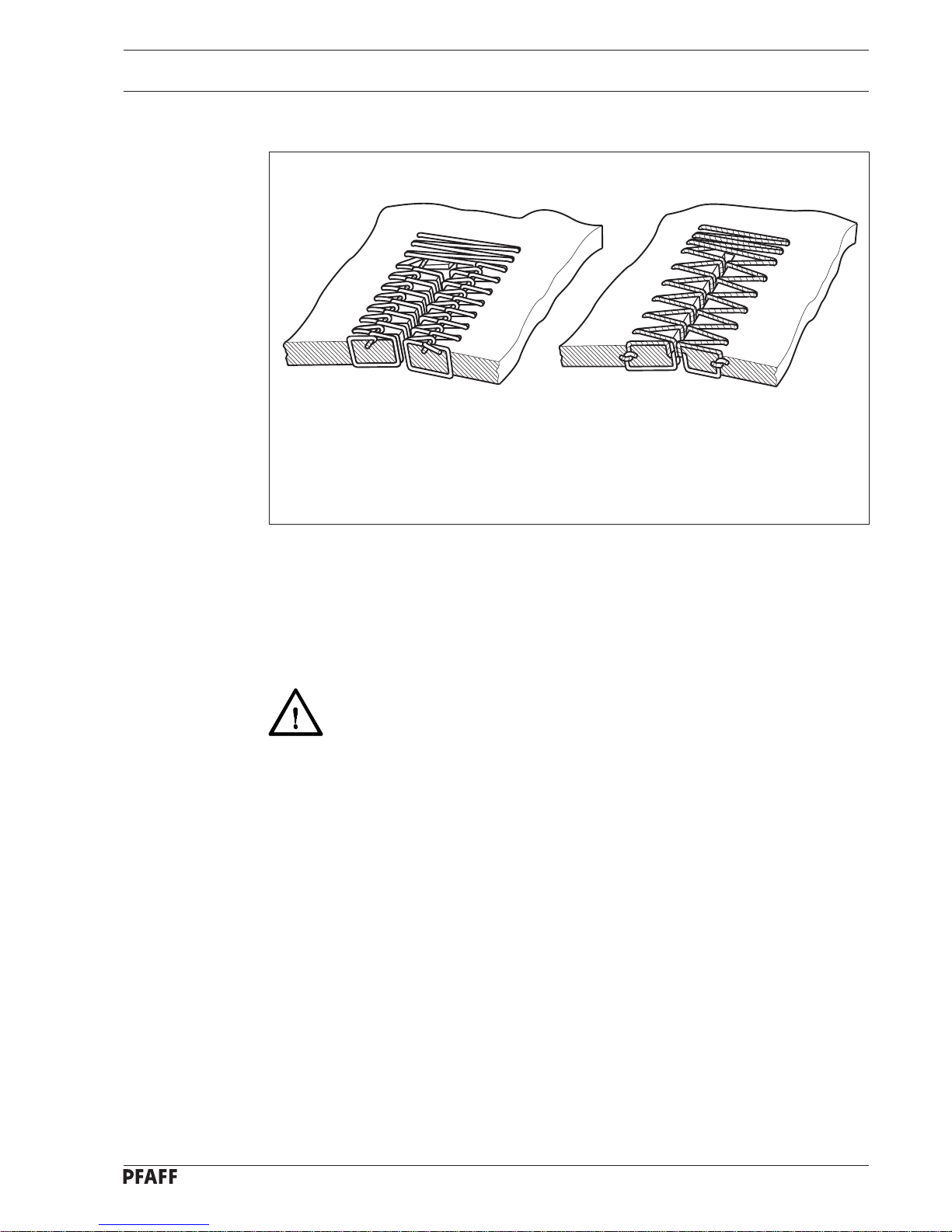
2 Proper use
The PFAFF 3117 is a machine for the automatic production of purl or flat buttonholes with
two square, flat bartacks on linen and apparel. If required, the buttonhole can be sewn
around twice.
Any and all uses of this machine which have not been approved of by the
manufacturer are considered to be inappropriate! The manufacturer cannot be
held liable for any damaged caused by the inappropriate use of the machine!
The appropriate use of the machine includes the observance of all operational,
adjustment, maintenance and repair measures required by the manufacturer!
Abb. 2 - 01
Purl Buttonholes Flat buttonholes
Page 12

Specifications
3 Specifications
Model:
A: ...........................................................................................For processing fine materials
B: ................................................................................... For processing medium materials
Speed:.........................................................................................................max. 4000 spm
Stitch type:................................................................................................ zigzag lockstitch
Stitch type:.................................................................................................................... 304
Needle bar stroke:.............................................................. 34.5 mm; adjustable to 38 mm
Workpiece thickness:........................................................................................ max. 4 mm
Clearance under the work clamp: ................................................................... max. 14 mm
Clearance for workpiece ( across sewing arm ): .................................................... 235 mm
Clearance for workpiece ( along sewing arm ):........................................................ 30 mm
Sewing construction: ......................................................................................... Buttonhole
Sewing construction size: ........................................................................... 40 mm x 6 mm
Length of cut: ........................................................................min. 6.4 mm; max. 31.7 mm
Stitch size: ........................................................................................................ max. 6 mm
Number of stitches: ................................................................................ min. 64; max. 400
Type of feed:..................................................................................................... Continuous
Sewing motor: ...........................................................Quick-Synchro QE 6040 - P11OS - 1
Power supply: ............................................................... 230 V + 10%, 50 / 60 Hz, 1 Phase
Power input: .................................................................................................. max. 0.6 kVA
Input rating:............................................................................................................. 0.7 kVA
Fuse protection: ............................................................................ 1 x 16 A, delayed action
Working air pressure:.................................................................................................. 6 bar
Air consumption:.................................................................................. ~1.21 / work cycles
Working noise level:
Emission at workplace at sewing cycle of 4s in and 2s out:........................ LPA < 81 dB(A)
( noise measurement in accordance with DIN 45 635-48-B-1 )
Dimensions of head:
Length:..................................................................................................... approx. 610 mm
Width: ....................................................................................................... approx. 200 mm
Height: ..................................................................................................... approx. 450 mm
Weight of head: .............................................................................................approx. 80 kg
Dimensions of stand:
Length:................................................................................................... approx. 1060 mm
Width: ...................................................................................................... approx. 600 mm
Height: ...................................................................................................... approx. 820 mm
Weight of stand including motor:...................................................................approx. 45 kg
Needle system:............................................................................... 438 or 265 or DPX 438
Needle thickness for processing fine materials: ...................................................... 60 - 70
Needle thickness for processing medium materials: ............................................. 80 - 100
3 - 1
Page 13

Disposal of the machine
4 - 1
4 Disposal of the machine
● The proper disposal of the machine is the responsibility of the customer.
● The materials used on the PFAFF 3117 are steel, aluminium, brass and various plastics.
The electrical equipment consists of plastics and copper.
● The machine is to be disposed of in accordance with the locally valid environmental
protection regulations.
Special care is to be taken that the oil reservoir and the oil leads are separately
disposed of in accordance with the locally valid environmental protection
regulations!
Page 14

Notes on testing in accordance with EN 60204-1
5 Notes on testing in accordance with EN 60204-1
This machine was tested in accordance with EN 60204-1 before delivery. The following
tests were carried out on the machine:
● Continuous connection of the protective conductor systems
a) Visual check
b) Check of the connection of the protective conductor
● Insulation check
● Voltage check
● Function check
5 - 1
Page 15
Transport, packaging and storage
6 - 1
6 Transport, packaging and storage
6.01 Transport to the customer’s premises
Within Germany, the machine is delivered without packaging. Certain machines are
packaged for export.
6.02 Transport within the customer’s premises
The manufacturer carries no liability for transport within the customer’s premises. Care is to
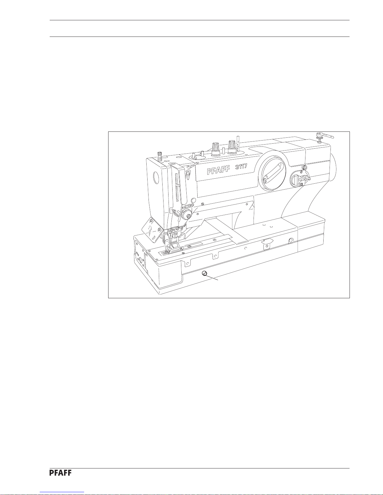
be taken to transport the machine in an upright position. The machine must be secured
against opening.
● To secure the machine against opening, tighten screw 1.
6.03 Disposal of the packaging
The packaging of the machine consists of wood, paper, cardboard and VCE fibre. The proper disposal of the packaging is the responsibility of the customer.
6.04 Storage
The machine can be stored for up to 6 months if not in use. During this time it should be
protected from dust and moisture.
For longer storage the individual parts of the machine, especially the moving parts, should
be protected against corrosion e.g. by a layer of oil.
Fig. 6 - 01
1
Page 16

Symbol key
7 Explanation of the symbols
In the following section of this Instruction Manual, certain tasks or important pieces of
information are accentuated by symbols. The symbols used have the following meanings:
Note, information
Clean, care
Servicing, repair, adjustment, maintenance
Lubrication, greasing, oiling
7 - 1
Page 17
Operational controls
8 - 1
8 Operational controls
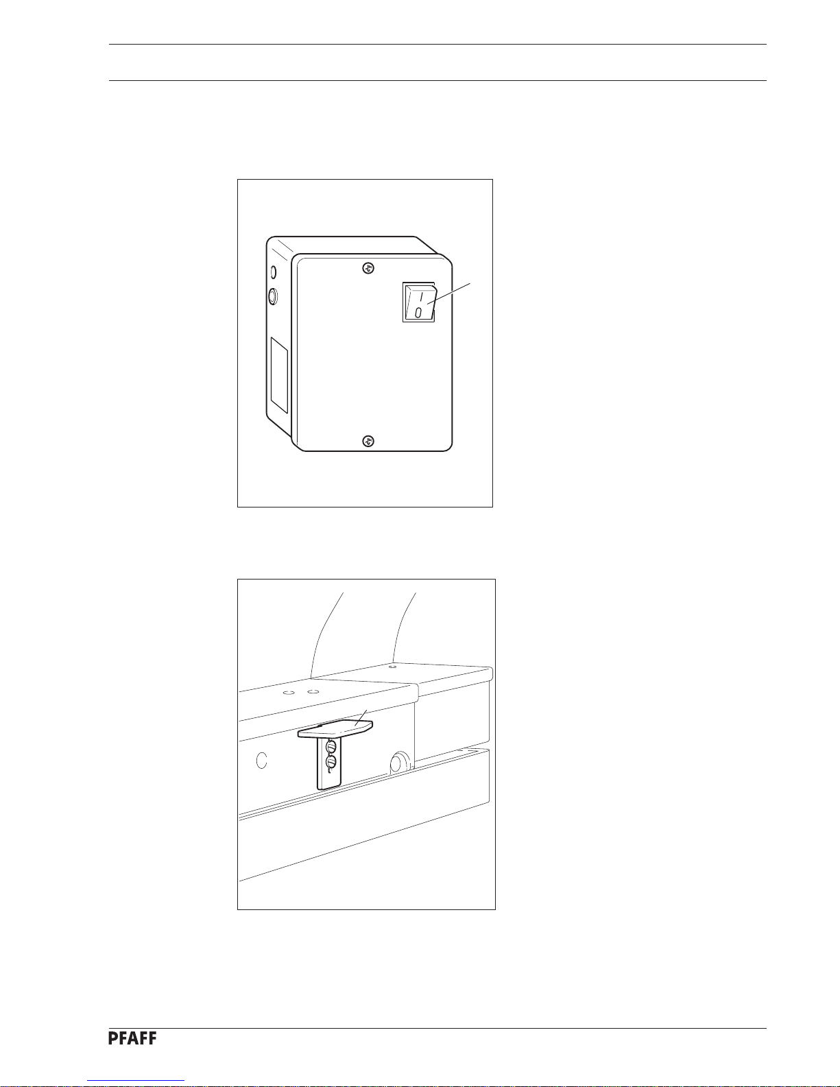
8.01 On / Off switch
● Switch the machine on and off with
switch 1. When the machine is on, the
control lamp in switch 1 is lit.
Fig. 8 - 01
Fig. 8 - 02
1
1
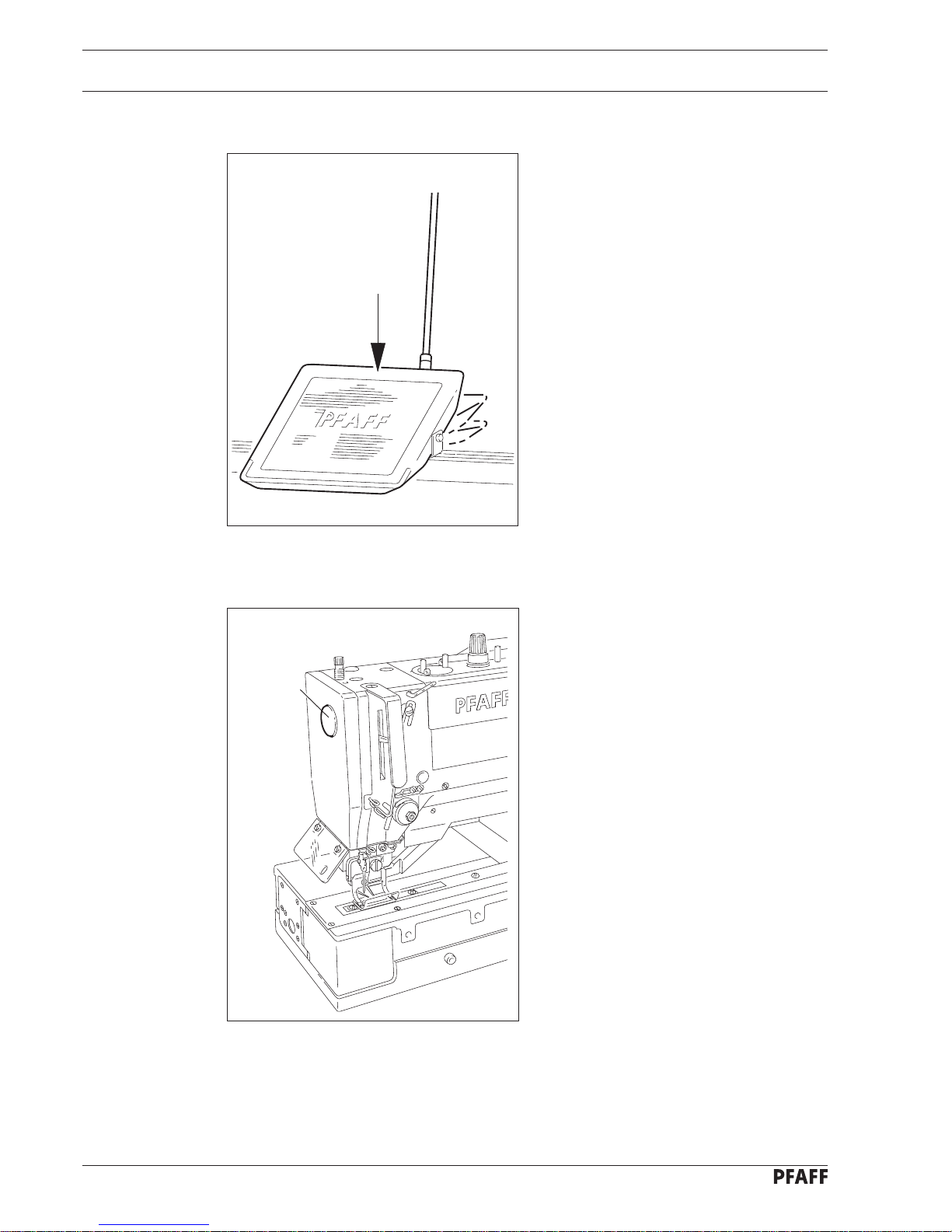
8.02 Stop button
● In case of danger and in emergency
situations, stop the machine by pressing
the stop button 1.
The motor stops in a controlled manner
( cover thread carrier moves to highest
position ).
The machine can be restarted by switching
the On / Off switch off and then back on
again.
Page 18
Operational controls
8 - 2
Fig. 8 - 03
+2
+1
0
Fig. 8 - 04
1
8.04 Button for stopping knife actuation
● If the actuation of the knife is to be
stopped, press button 1.
8.03 Functions of the pedal
0 = Machine stop
+1 = Work clamp down
+2 = Sew
Page 19
Operational controls
8 - 3
QUICK
digital
G
F
+
1
2
Programm
n
-
Fig. 8 - 05
T3 T4T2T143
1
2
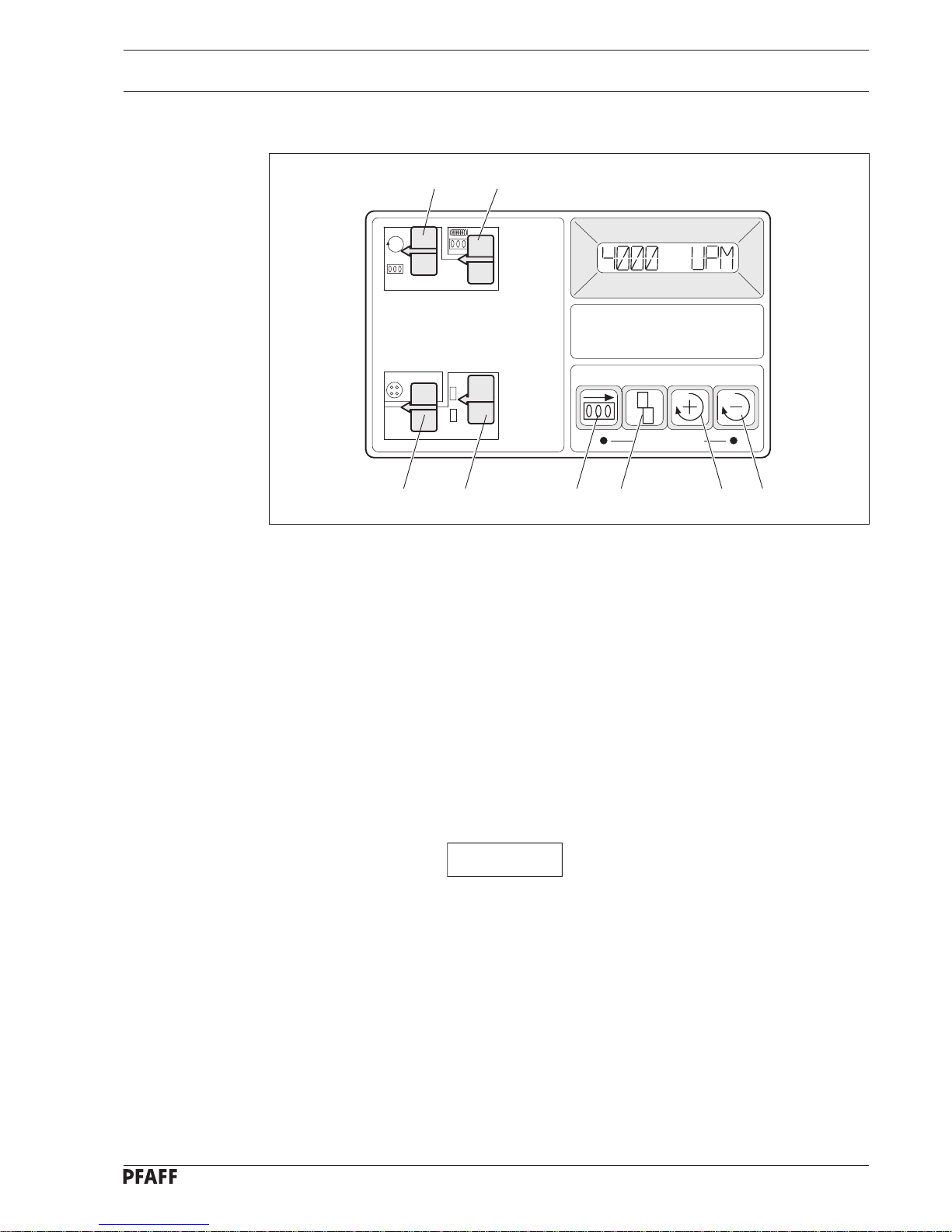
8.05.01 Functions of the switches and buttons
Switch 1
is for changing between the RPM and number-of-buttonholes readings in the display.
When this switch is up, the RPM reading is displayed. The RPM can be altered using
buttons T3 ( + ) and T4 ( - ).
When this switch is down, the number of buttonholes sewn is displayed. The maximum
number which can be displayed is 65536.
By holding button T4 pressed and pressing T2 briefly this counter can be reset to zero.
To do so the buttons must be held for approx. 1 second.
Switch 2
Is for setting the countdown mechanism.
When the switch is up, the following reading appears in the display:
XXX YYY
XXX = the total number of buttonholes to be sewn.
YYY = the number of buttonholes still to be sewn.
By pressing button T2, the YYY reading ( buttonholes remaining ) is made to equal the XXX
reading (total buttonholes).
The range for the total number of buttonholes lies between 0 and 500.
A start is only possible when switch 2 is down ( off ).
In normal operation, a renewed start of the machine is impossible when the number of
buttonholes remaining is 0 ( YYY = 000 ). The fault reading BOBBIN appears in the display.
After changing the bobbin, this disturbance can be removed by pressing button T2.
This returns the number of buttons remaining ( YYY ) to the same level as the number of
buttons to be sewn ( XXX ).
8.05 Functions of the quick control panel
Page 20
Operational controls
8 - 4
QUICK
digital
G
F
+
1
2
Programm
n
-
Fig. 8 - 05
T3 T4T2T13
12
4
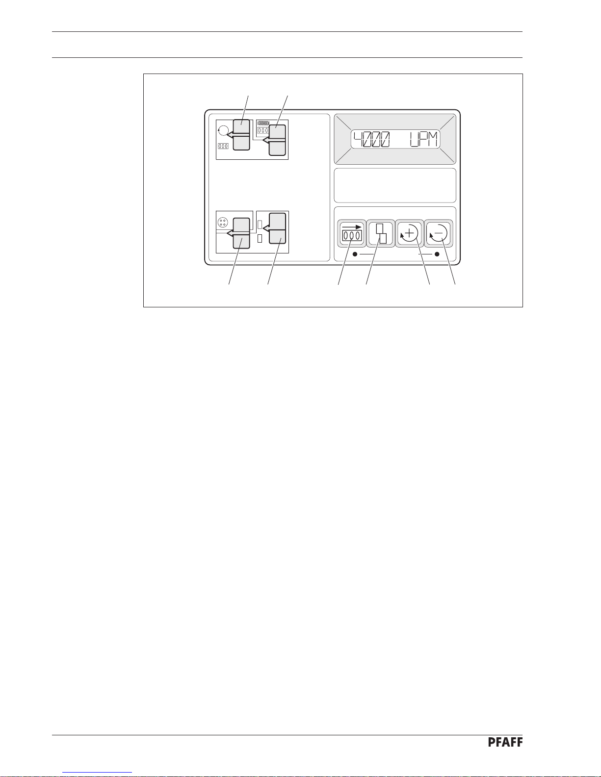
Switch 3
serves to start and stop winding the bobbin.
When the switch is up, winding can take place as long as the foot pedal is pressed and one
cycle is not yet completed.
Switch 4
switches between work cycles.
When the switch is up the machine carries out only one cycle.
When the switch is down the machine carries out two cycles.
8.05.02 Switching the countdown device on/off
When the machine is switched on, the countdown mechanism (parameter 620) can be
switched on and off by the operating personnel as follows:
● Press buttons T1 and T4 simultaneously.
● Press button T2.
● Press button T3 or T4.
I = countdown ON
II = countdown OFF
● Press buttons T1 and T4 simultaneously.
Page 21

Operational controls
8 - 5
8.05.03 List of parameters
Group Parameter Explanation Adjustment range Standard value
1 116 No. of stitches for reduced 0 - 30 3
speed n1
117 Reduced speed n1 50 - 2250 1000
143 Reduced speed n3 1000 - 2700 2000
4 410 Alteration of speed n2 II
in steps of:
I = 10 RPM
II = 100 RPM
417 I = Display mode display II
machine unit counter
II = Display mode display
daily unit counter or n2
6 605 I = Actual RPM in the display II
II = No actual RPM in the
display
620 I = Countdown mechanism ON II
II = Countdown mechanism OFF
659 I = Normal running II
after fault correction
II = Reduced speed n3
after fault correction
7 718 Cycle brake 0 - 30 3
722 Acceleration ramp 1 - 50 44
723 Brake ramp 1 - 50 48
730 Lift delay for 0 - 250 100
work clamp
733 Language 1 - 6 ENGL
8 800 I = left running for sewing I
(Viewpoint Drive-BLM)
II = right running for sewing
884 P share speed regulation 1 - 50 10
In groups 2, 3 and 5 there are no parameters.
For further information see the Operation Manual of the motor.
Page 22

Operational controls
8 - 6
8.05.04 Fault indication in the display
Faults are documented via the quick control panel.
K-faults
K-faults are machine specific faults. The following readings can appear in the quick-
control-panel display:
K1 = pedal ( S1.1 / S1.2 ).
3116 = no autoselect.
resistance ( 470 Ohm ) in plug test INP.
KNIFE = knife not in start position ( S21 ).
BOBBIN = bobbin is empty or wrong counter value is set.
CLAMP = check switch and/or magnet valve ( S3 ).
START = check plug connection, magnet valve and / or switch ( S2 ).
STOP = machine has been stopped via Machine-Stop button ( S5 ).
POSITION = control cam not in basic position ( S8 ).
After the fault reading BASIC, the machine runs with the reduction speed in its starting
position after being restarted with the pedal.
The fault reading BOBBIN can be anulled by pressing button T2 or machine ON / OFF.
All other fault readings can only be anulled with the machine ON / OFF switch.
Q-faults
Q-faults are motor specific faults. The following readings can appear in the display of the
quick control panel:
Q2 = No impulses from position transmitter or impulses from position transmitter
not recognized.
Q10 = Commutation plug not inserted.
If other Q-faults are displayed, the motor control box should be changed.
It is also possible that these fault readings can be caused by cable breakages. This should
be checked.
By pressing button T2 the work clamp can be raised or lowered when the
machine is in basic position.
Page 23
Mounting and initial operation
9 - 1
9 Mounting and initial operation
This machine may only be mounted and put into operation by qualified
specialists! All relevant safety regulations are to be adhered to!
9.01 Mounting
Connections for electrical and compressed air supplies must be available at the machine’s
location ( see chapter 3 Specifications ).
A solid, horizontal surface and adequate lighting must also be guaranteed.
Due to reasons of packaging, the table top is lowered on machines with
stands. When putting the machine into operation, the table top should be
raised again or adjusted to an ergonomically suitable height.
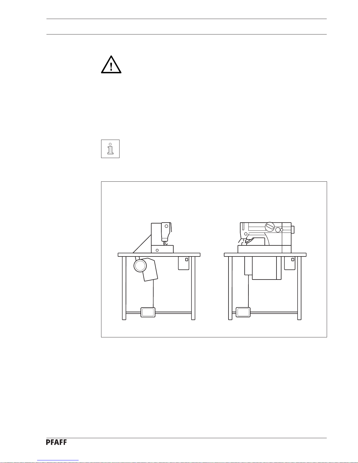
The PFAFF 3117 is available in two mountings.
Fig. 9 - 01
Mounting 1
= crosswise
Mounting 2
= lengthwise
● Mounting 1 is perpendicular to the operator.
● Mounting 2 is parallel to the operator.
Page 24

Mounting and initial operation
9 - 2
9.02 Initial operation
● Check the machine for any possible damage, especially the electrical and pneumatic
leads.
● Clean the machine thoroughly and then oil it ( see chapter 13 Maintenance and care ).
● Connect the machine to the power supply.
● Connect the machine to the compressed air supply. The manometer should display an air
pressure level of approx. 6 bar. Adjust to this value if necessary ( see chapter 13.03
Checking the air pressure ).
● Carry out a test run.
Page 25
Switching the machine On / Off
10 - 1
10 Switching the Machine On / Off
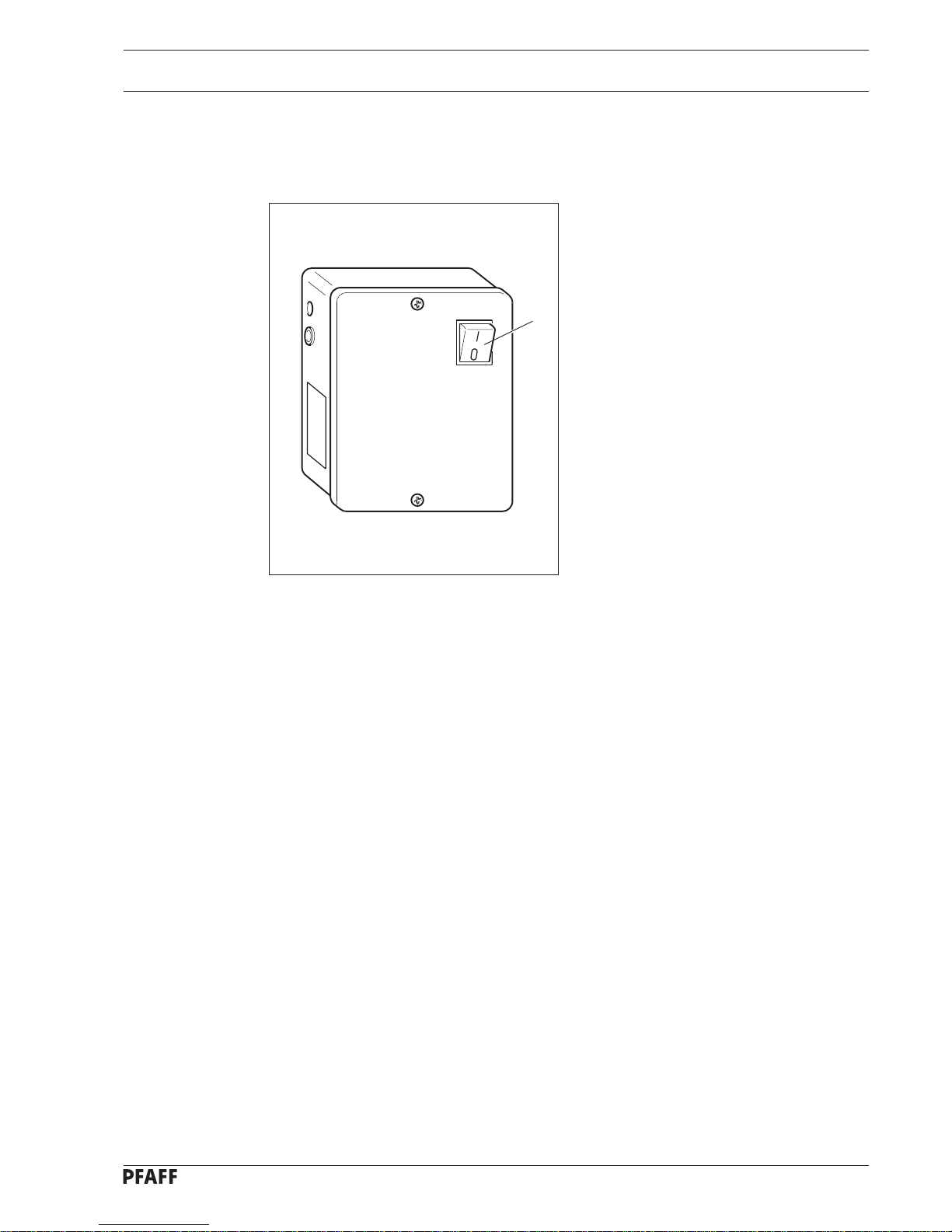
10.01 On / Off switch
● Switch the machine on and off at
switch 1. When the machine is switched
on, the control lamp in switch 1 is lit.
Fig. 8 - 01
1
Page 26
Preparation
11 Preparation
All regulations and notes in this Instruction manual are to be adhered to.
Special attention is to be taken to the safety requirements!
All Preparation work must be carried out only by appropriately trained persons.
The machine is to be separated from the power supply at the On/Off switch or
by pulling the plug out of the socket whenever carrying out preparation work!
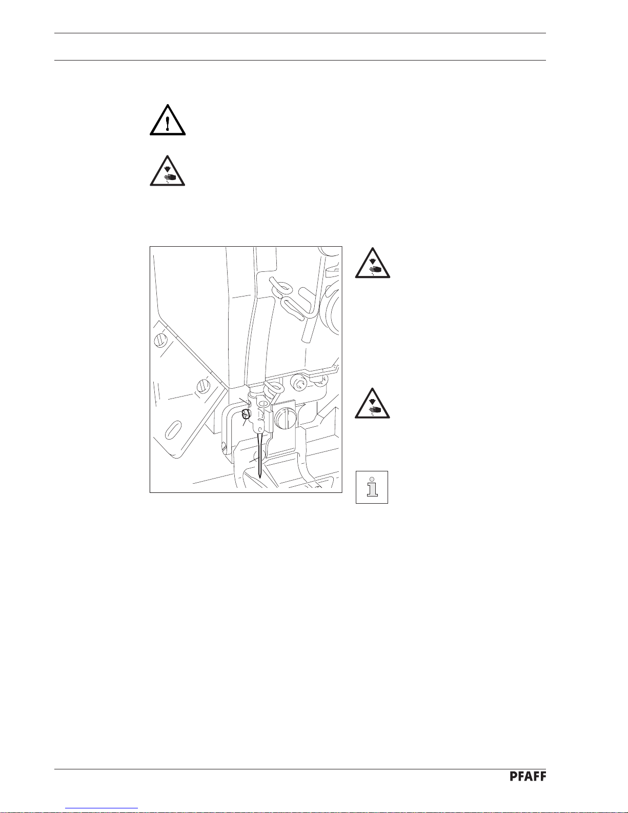
11.01 Inserting the needle
Switch off the machine!
● Loosen the needle retaining screw 1.
● Insert needle 2 as far as possible.
● The long needle-groove must be facing
the knife.
● Tighten the needle retaining screw 1.
Attention! needle point and
knife blade! Danger of injury!
Hole 3 can be used to check if
the needle 2 is inserted
properly. By inserting a suitable
tool into hole 3 pieces of
broken needle can be
removed.
11 - 1
Fig. 11 - 01
1
3
2
Page 27
Preparation
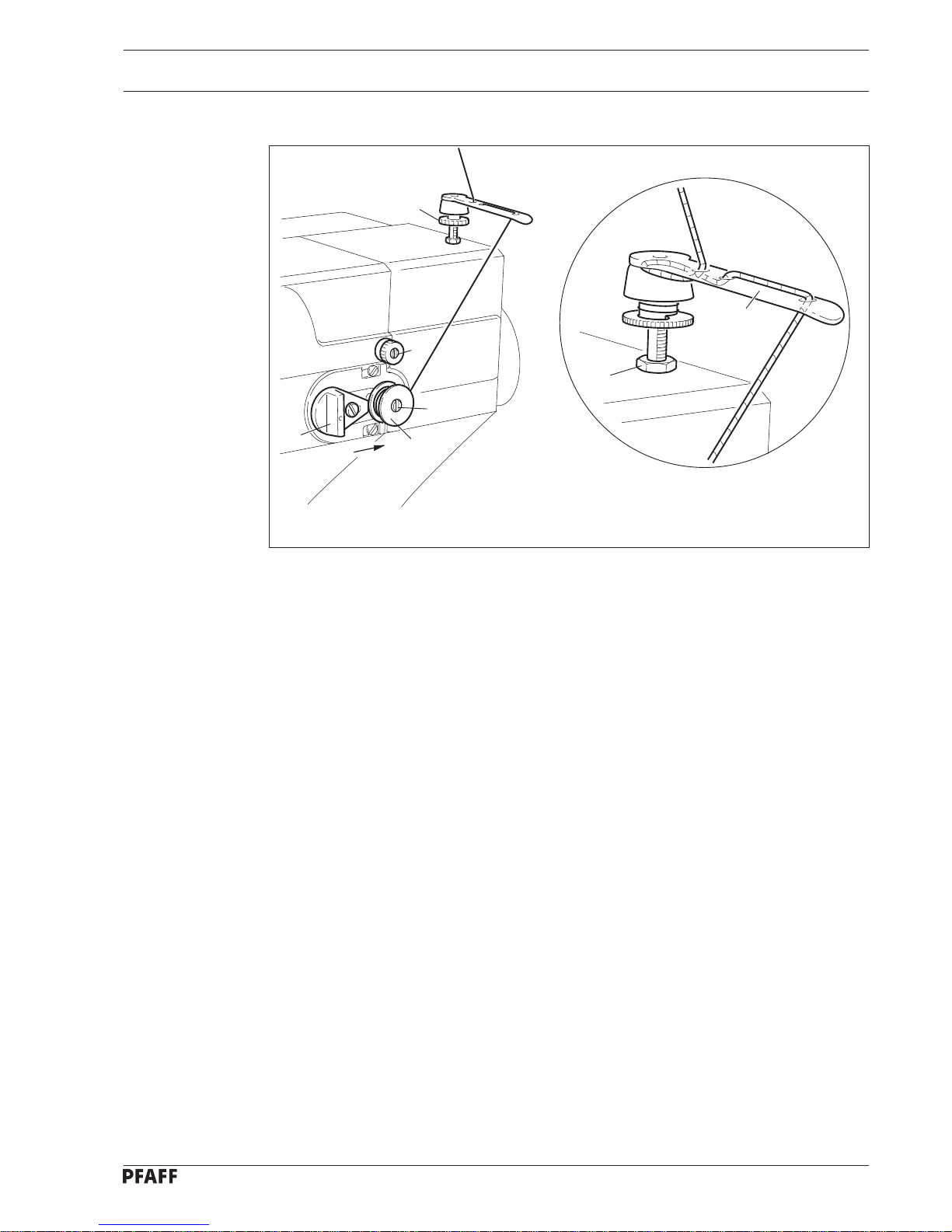
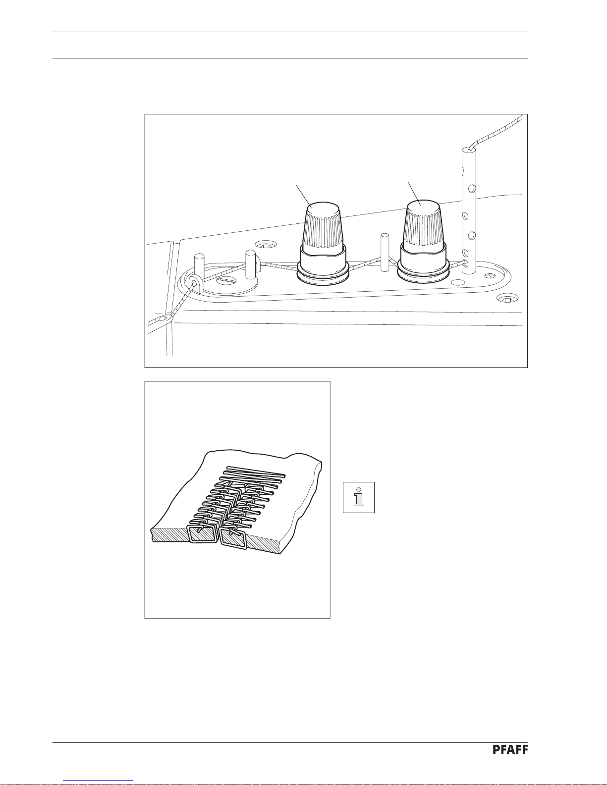
Abb. 11 - 02
11 - 2
6
3
7
4
1
2
5
● Place an empty bobbin 1 onto the bobbin shaft 2.
● Thread the machine in accordance with Fig. 11-02.
● Push key 3 to the end of the bobbin shaft 2.
● Regulate the thread tension by turning the milled screw 4.
● Push the foot pedal.
● The bobbin winder stops automatically when the bobbin 1 is full.
● Clamp the thread coming from the spool in the clamp 5 and snap the thread.
● For bobbin winding see section 8.05 Functions of the quick control panel
( switch 3 ).
If the thread winds unevenly:
● loosen nut 6.
● Turn the thread guide 7 accordingly.
● Tighten nut 6.
11.02 Winding the bobbin thread, adjusting the thread tension
Page 28
Preparation
Fig. 11 - 03
Fig. 11 - 04
11 - 3
1
2
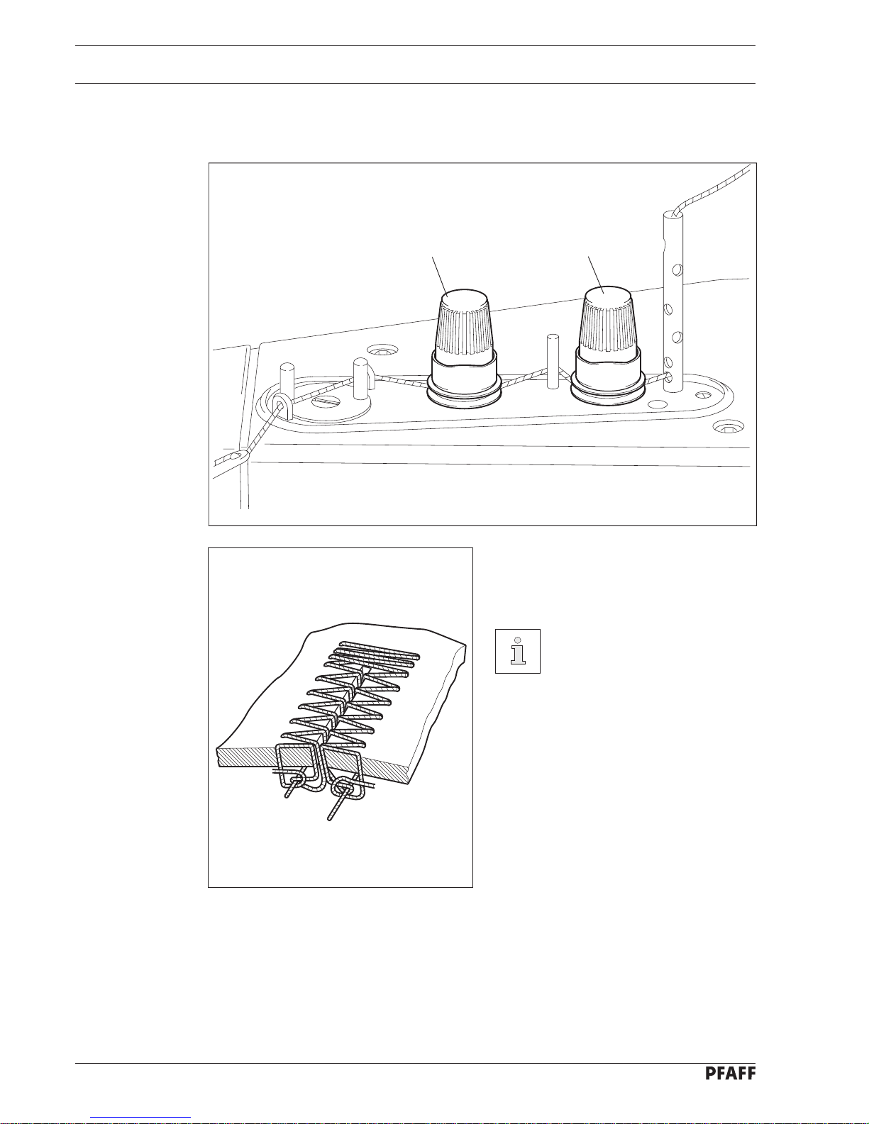
● Open tensioner 1 as far as possible.
● Adjust tensioner 2 so that the knots of
the stitches are in the middle of the
material.
● Adjust tensioner 1 so that the knots of
the purl stitches are pulled up.
Carry out this adjustment with
needle and bobbin threads of
different colours.
11.03 Adjusting the needle thread tension on purl buttonholes and flat
bartacks
Page 29
Preparation
Fig. 11 - 05
7
4 cm
11 - 4
3
4
6
5
2
1
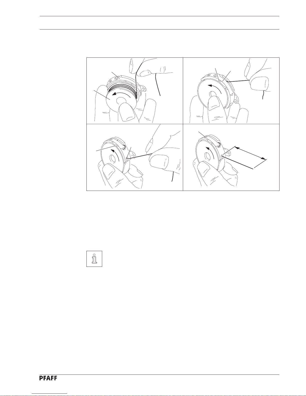
● Insert bobbin 1 into bobbin case 2.
● Pass the thread through slot 3 and under spring 4.
● Then pass the thread into slot 5.
● Pass the thread out of hole 6 again.
● Adjust the thread tension by turning screw 7.
● Use the enclosed tool for this process.
The bobbin thread should be able to be pulled easily and evenly out of the
bobbin case 2 for sewing purl buttonholes. Therefore, turn screw 7 so that the
bobbin case 2, with a full bobbin 1, slides slowly downwards when hanging
freely from the thread.
11.04 Threading the bobbin case, adjusting the thread tension
on purlbuttonholes
Page 30
Preparation
Fig. 11 - 03
11 - 5
Fig. 11 - 06
2
1
11.05 Adjusting the needle thread tension on flat buttonholes
and flat bartacks
● Adjust tensioners 1 and 2 ( less tension )
so that the knots in the stitches are
pulled onto the underside of the material.
Carry out this adjustment with
a needle thread and a bobbin
thread of different colours.
Page 31

Preparation
Fig. 11 - 07
8
43
4 cm
11 - 6
5
6
1
2
7
11.06 Threading the bobbin case, adjusting the thread tension
on flat buttonholes
● Insert bobbin 1 into bobbin case2.
● Pass the thread through slot 3 and under spring 4.
● Then pass the thread into slot 5.
● Then pass the thread into slot 6 again.
● Pass the thread through eye 7.
● Adjust the thread tension by turning screw 8.
● Use the enclosed tool for this process.
When sewing flat buttonholes the bobbin thread must have enough tension so
that the knotting of the bobbin thread takes place on the underside of the
material.
Page 32

Preparation
11 - 7
Thread guide for
synthetic threads
Thread guide for cotton
covered threads
Fig. 11 - 08
11.07 Threading the needle thread
Switch the machine off!
● Thread the needle thread in accordance with fig. 11 - 08.
Attention! Needle point and knife blade! Danger of injury!
Page 33

Preparation
Fig. 11 - 09
11 - 8
Fig. 11 - 10
1
3
12
11.09 Adjusting the sewing pressure
● Adjust the pressure on the work clamp
by turning the adjustment screw 1.
The sewing pressure is
dependent on the material to
be sewn and must be adjusted
accordingly. The pressure is
correct when the workpiece is
fed securely and evenly without
feed marks being left on it.
11.08 Inserting the bobbin case
Switch the machine off!
● Open the cover 1 to the hook
compartment.
● Insert the bobbin case 2 into the bobbin
case carrier 3.
● Close the hook compartment with the
cover 1.
Page 34

Preparation
Fig. 11 - 11
Fig. 11 - 12
11 - 9
1
1
2
11.11 Adjusting the left purl seam position
● Adjust the left purl seam position by
turning the milled screw 1.
11.10 Adjusting the purl seam width
● Open cover 1.
● Adjust the purl seam width by turning
the milled screw 2.
Any larger change to the purl
seam width also requires the
adjustment of the right purl
seam position.
Page 35

Preparation
Fig. 11 - 13
Fig. 11 - 14
11 - 10
1
2
1
11.13 Adjusting the bartack width
● Adjust the bartack width by turning the
milled screw 2.
● Close cover 1.
The bartack width is set
correctly when the bartack
stitches cover both purl seams.
11.12 Adjusting the right purl seam position
● Adjust the right purl seam position by
turning the milled screw 1.
The right purl seam position
must be adjusted in relation to
the left purl seam position so
that the cutting area between
the two seams is adequately
wide.
Page 36

Preparation
Fig. 11 - 15
11 - 11
1
2
3
4
5
Switch the machine off!
● Open the bed slide 1.
● Loosen nut 2.
● Move bolt 3 in the slot so that the pointer 4 is pointing to the desired value. Only the
scale on the inside of the curve is to be used here.
● Tighten nut 2.
● Close bed slide 1.
The maximum buttonhole length must be secured by the stop 5 in such a way
that the work clamp mounted for this buttonhole length is adequate. When
changing to a longer work clamp the stop 5 must also be changed accordingly.
11.14 Adjusting the buttonhole length
Page 37

Preparation
Fig. 11 - 16
Fig. 11 - 17
11 - 12
2
1
3
2
1
4
11.16 Changing the knife
Switch the machine off!
● Remove screw 1.
● Remove the knife 2 from screw 1.
● Insert a new knife 2 in accordance with
the buttonhole length.
● Adjust the height of the knife 2 ( see
chapter 14.12.09 Height with the
buttonhole cutter or chapter
14.12.10 Height with the buttonhole
punch ).
● Tighten screw 1.
Sharp blade!
Danger of injury!
11.15 Adjusting the number of stitches per buttonhole
Switch the machine off!
● Open cover 1.
● Remove cogs 2 and 3.
● Select cogs 2 and 3 in accordance with
chart 4.
● Replace cogs 2 and 3.
● Close cover 1.
Page 38

Preparation
11 - 13
Fig. 11 - 18
2
Fig. 11 - 19
3
2
1
1
11.18 Changing the work clamp
Switch the machine off!
● Disassemble the knife.
● Loosen screw 1.
● Change the work clamp 2.
● Tighten screw 1.
● Reassemble the knife.
When changing to a longer
work clamp, the stop 5 ( see
Fig. 11 - 15 ) must also be
changed accordingly.
11.17 Changing the plastic insert in the needle plate
Switch the machine off!
● Loosen screw 1.
● Loosen the feeder 2.
● Change or rotate the plastic insert 3.
● Tighten screw 1.
Page 39

Sewing
12 - 1
12 Sewing
Do not operate the machine without its take up lever guard 1, finger guard 2, or
eye guard 3! The hand crank 4 must be folded in during operation! The cover 5
and the bed slide 6 must be closed. The machine may only be operated when
all covers are completely installed and the belt guard cover is closed! Danger of
injury!
The machine must only be operated by appropriately trained personnel! The
operating personnel is also responsible for ensuring that only authorized
personnel are allowed into the area of potential danger around the machine.
12.01 Test seam
After any form of preparation, after all maintenance and repair work and when changing
materials a test seam is to be sewn.
12.02 Sewing with a single cycle
● Push switch 4 on the quick control panel up ( see chapter 8.05 Functions of the
quick control panel ).
● Insert the workpiece.
● Bring the foot pedal into its + 1 position which lowers the work clamp.
● Move the foot pedal into position + 2. One buttonhole will be sewn.
● Remove the workpiece or move it into its next position.
Fig. 12 - 01
5
6
2
4
1
3
Page 40

Sewing
12 - 2
Fig. 8 - 02
1
12.03 Sewing with a double cycle
● Push switch 4 on the quick control panel down ( see chapter 8.05 Functions of the
Quick control panel ).
● Insert the workpiece.
● Bring the foot pedal into its + 1 position which lowers the work clamp.
● Move the foot pedal into position + 2. One buttonhole will be sewn around twice.
● Remove the workpiece or move it into its next position.
12.04 Stopping the machine in an emergency
● Push the button 1 down.
Page 41

Care and maintenance
13 - 1
13 Care and maintenance
Cleaning .................................................................................................................. daily
Check oil level....................................................................................... daily before use
Fill oil.............................................................................................................as required
Check oil level for hook lubrication..................................................................... weekly
Fill oil for hook lubrication..............................................................................as required
Check air pressure ................................................................................ daily before use
13.01 Cleaning
Switch the machine off!
● Open the cover 1.
● Clean the hook 2 and hook compartment
3 daily.
● Close the cover 1.
Fig. 13 - 01
3
1
2
Page 42

Care and maintenance
13 - 2
Fig. 13 - 02
Fig. 13 - 03
2
1
3
Kl.
Erz.Nr.
Oberteil-Nummer.
1
As required:
Switch the machine off!
● Lay the head on its side.
● Fill the oil reservoir 2 through hole 1 up
to marking 3.
● Return head back to its upright position
with both hands.
Danger of crushing between
machine head and table top!
Only use oil with a mean
viscosity of 22.0 mm2/s at 40°C
and a density of 0.865 g/cm3 at
15°C!
We recommend PFAFF sewing machine oil Part No. 280-1-120 144.
13.02 Lubricating
13.02.01 General lubricating
● Check the oil level in the glass 1 before
every use.
Page 43

Care and maintenance
13 - 3
Fig. 13 - 04
Fig. 13 - 05
12
3
1
As required:
Switch the machine off!
● Lay the head on its side if required.
● Fill the oil reservoir 2 through hole 1 up
to marking 2.
● Return head back to its upright position
with both hands.
Danger of crushing between
machine head and table top!
Only use oil with a mean
viscosity of 10.3 mm2/s at 40°C
and a density of 0.847 g/cm3 at
15°C!
We recommend PFAFF sewing machine oil Part No. 280-1-120 105.
13.02.02 Lubricating the hook
● Check the oil level in the glass 1 every
week.
Page 44

Care and maintenance
13 - 4
Fig. 13 - 06
2
3
1
13.03 Checking the air pressure
● Check the air pressure on the manometer 1 before every use of the machine.
● The manometer 1 should display a
pressure of approx. 6 bar .
● If necessary, adjust to this value.
● To do this, lift button 2 and twist it until a
value of approx. 6 bar is shown on the
manometer.
When the compressed air is
turned off, condensation
escapes through the release
valve 3. Place a suitable
container under this valve!
Page 45

Adjustment
14 - 1
14 Adjustment
All relevant safety regulations are to be adhered to! The machine is to be
separated from the power supply before all adjustment work and to be secured
against accidentally being turned back on!
All adjustments in these adjustment instructions are based on a completely
installed machine. Covers on the machine which have to be removed and
replaced for checks and adjustment work are not mentioned.
The PFAFF 3117 is set up for Singer needles at the factory. When using
needles from other manufacturers the hook settings are to be checked.
14.01 Tools, gauges and other accessories
● Screwdrivers with blade width from 2 to 10 mm
● Screwdrivers with blade width from 7 to 14 mm
● Allan keys from 1.5 to 6 mm
● Offgrub screwdrivers, Part No. 91-029 339-91
● Metal rule, Part No. 08-880 218-00
● Terminal screw, Part No. 08-880 137-00
● Needle rise gauge 2.4 mm, Part No. 61-111 600-09
● Adjustment gauge, Part No. 61-111 635-86
● Knife adjustment gauge, Part No. 61-111 635-85
● Needles, system 438 or 265 or DPX 438
● Sewing thread and test material
● Sewing machine oil: mean viscosity of 22.0 mm2/s at 40°C
Density 0.865 g/cm3 at 15°C
Part No. 280-1-120 144
● Sewing machine oil: mean viscosity of 10.3 mm2/s at 40°C
Density 0.847 g/cm3 at 15°C
Part No. 280-1-120 105
Page 46

Adjustment
14 - 2
14.02 Machine positions and needle bar positions
When the machine is switched off, the machine positions can be attained by
turning the handwheel 1, by turning the shaft 2 or by turning the drive pulley 3.
The needle bar positions can be attained by turning the drive pulley 3.
At the end of a program the marking 4 on the control cam must be aligned with
the marking 5 on the housing.
● Turn the handwheel 1 clockwise.
or
● Turn the shaft 2 counter clockwise with a screwdriver.
or
● Turn the drive pulley 3 in its direction of rotation.
Before turning the drive pulley 3 the stop motion device must be engaged! The
separate machine positions should only be approached with the work clamp is
touching.
2
3
1
Fig. 14 - 01
4
5
Page 47

Adjustment
14 - 3
1
Fig. 14 - 02
2
14.03 Engaging/disengaging the stop motion device
Requirement
Before turning the drive pulley, the stop motion device must be engaged!
By engaging the stop motion device, collisions between the needle and the
needle thread scissor are avoided.
● Push the switching lever 1 down to engage the stop motion device.
● Lift the disengaging lever 2 to disengage the stop motion device.
Page 48

Adjustment
14 - 4
4
1
2
5
3
8
7
6
Fig. 14 - 03
● Loosen nut 3 and bring the tightening roller 4 to a resting position by turning the lever 5
on the toothed belt 1.
● Then press the tightening roller 4 another 5 mm more against the toothed belt 1.
● Tighten nut 3 .
● Loosen nut 6 and displace the tightening roller 7 by turning the eccentric 8 in accordance
with the requirement.
● Tighten nut 6.
In the case of noise occuring, displace the tension rollers once again.
14.04 Toothed belt drives
Requirement
The toothed belts 1 and 2 should be tight enough to guarantee a perfect transmission of
power. There should be virtually no noticeable play between the toothed belts and the
toothed belt cogs.
Page 49

Adjustment
14 - 5
11.5 mm
13.0 mm
3
4
2
1
11.5 mm
12.5 mm
Fig. 14 - 04
● Adjust to the measurements given by turning the milled screws 1 to 4.
14.05 Basic position of the milled screws on the feed regulator
Requirement
The milled screws 1 to 4 should be set at the following measurements:
● Milled screw 1 ( bartack width ) = 11.5 mm
● Milled screw 2 ( buttonhole seam width ) = 12.5 mm
● Milled screw 3 ( buttonhole seam position right ) = 13.0 mm
● Milled screw 4 ( buttonhole seam position left ) = 11.5 mm
Page 50

Adjustment
14 - 6
1
2
11.5 mm
Fig. 14 - 05
● Bring the needle bar to its BDC.
● Loosen the screw 2 that can now be seen.
● Move the needle bar 1 in accordance with the requirement.
● Tighten screw 2.
14.06 Needle bar and needle
14.06.01 Pre-adjusting the needle bar height
Requirement
With the needle bar at its BDC, there should be a clearance of 11.5 mm between the
bottom edge of the needle bar 1 and the needle plate.
Page 51

Adjustment
14 - 7
Fig. 14 - 06
1
2
● Engage the stop motion device.
● Bring the machine into program end position.
● Lift the work clamp and place a piece of paper underneath it.
● Turn the drive pulley in its direction of rotation until the needle perforates.
● Then turn the drive pulley back until the needle perforates again.
● Loosen nut 1 for the adjustment and turn screw 2 in accordance with the requirement.
● Tighten nut 1.
● Disengage the stop motion device.
14.06.02 Needle bar in its program end position
Requirement
At its program end position the needle should carry out a minimal zigzag movement.
Page 52

Adjustment
14 - 8
Fig. 14 - 07
2
4
1
3
● Loosen the grub screws on the handwheel and remove the handwheel.
● Loosen the screw 3 that can now be seen, so that the needle bar pendulum 2 can be
moved.
● Loosen screws 4 and move the guide piece 1 in accordance with the requirement.
● Tighten screws 4.
For the following adjustments, the handwheel remains dismounted and screw
3 remains loosened.
14.06.03 Needle bar pendulum
Requirement
The guide piece 1 should be touching the needle bar pendulum 2 on axis, without play.
Page 53

Adjustment
14 - 9
4
3
3
1
3
3
Fig. 14 - 08
2
● Insert the needle 1. See chapter 11.01 Inserting the needle.
● Loosen screws 3 and move the needle plate carrier 4 in accordance with the require-
ment.
● Tighten screws 3.
14.06.04 Needle plate to needle
Requirement
The needle 1 should should be positioned in the middle of the needle hole 2.
Page 54

Adjustment
14 - 10
● Bring the machine into its program end position.
● Engage the stop motion device.
● Bring the needle bar to its BDC.
● Move the needle1 in accordance with the requirement.
● Tighten screw 3.
● Remount the handwheel. ( cf. chapter 14.06.01 Pre-adjusting the needle bar height )
● Disengage the stop motion device.
Fig. 14 - 09
3
1
2
14.06.05 Basic position of the needle bar
Requirement
In the program end position and with the needle bar at its BDC, the needle 1 should be
positioned at the left edge of the knife actuating hole 2.
Carry out this adjustment with a needle plate with a knife actuating hole
mounted.
Page 55

Adjustment
14 - 11
● Engage the stop motion device
● Bring the machine into the initial bartack position ( rear bartack ).
● Remove one feed gear.
● Turn the drive pulley in its direction of rotation and observe the lateral movement of the
needle.
● Loosen the grub screws 1 and turn the cog 2 in accordance with the requirement.
● Tighten the grub screws 1.
● Disengage the stop motion device.
● Remount the feed gear.
Fig. 14 - 10
2
1
14.06.06 Lateral movement of the needle
Requirement
The lateral movement of the needle should be finished above the needle plate.
Page 56

Adjustment
14 - 12
Fig. 14 - 11
1
2
● Bring the machine into the left buttonhole seam position.
● Engage the stop motion device.
● Bring the needle to the right perforation.
● Turn milled screw 1 in accordance with requirement 1.
● Bring the needle to the left perforation.
● Turn milled screw 2 in accordance with requirement 2.
● Disengage the stop motion device.
14.07 Seam construction
14.07.01 Left buttonhole seam
Requirement
1. The needle should be positioned at the right perforation of the left buttonhole seam at
the left edge of the knife actuating hole.
2. The left perforation must be within the needle hole.
Carry out this adjustment with a needle plate with a knife actuating hole
mounted.
Page 57

Adjustment
14 - 13
Fig. 14 - 12
1
● Bring the machine into the right buttonhole seam position.
● Engage the stop motion device.
● Bring the needle to the left perforation.
● Turn milled screw 1 in accordance with the requirement.
● Disengage the stop motion device.
14.07.02 Right buttonhole seam
Requirement
The needle should be positioned at the left perforation of the right buttonhole seam at the
right edge of the knife actuating hole.
Carry out this adjustment with a needle plate with a knife actuating hole
mounted.
Page 58

Adjustment
14 - 14
Fig. 14 - 13
4
2
1
3
5
● Bring the machine in the first bartack position.
● Turn milled screw 1 in accordance with requirement 1.
● Loosen screws 2 and move trip 3 for the first bartack in accordance with requirement 2.
● Tighten screws 2.
● Loosen screws 4 and move trip 5 for the end bartack in accordance with requirement 3.
● Tighten screws 4.
14.07.03 Bartack
Requirement
1. The bartack width must be the same as the width of both buttonhole seams together.
2. The first bartack must only be at its full width when the buttonhole seam displacement
is complete. Within the range of the first bartack, the movement of the needle must
not pass over the left edge of the buttonhole seam.
3. The end bartack must begin early enough so that the beginning of the left buttonhole
seam is covered.
Page 59

Adjustment
14 - 15
Bartack width
Bartack stitches
(first or rear bartack)
Zero line when sewing
the left buttonhole seam
Reinforcing stitches
at the beginning of the buttonhole
Zero line when sewing the
right buttonhole seam
Bartack stitches
(end or front bartack)
Reinforcing stitches at the end
of the buttonhole
Buttonhole seam width
Cutting space width
Reinforcing stitch
Buttonhole seam
stitches
Fig. 14 - 14
14.07.04 Description of the seam construction
Page 60

Adjustment
14 - 16
1
2
56
7
3
4
Fig. 14 - 15
1 = False! The right buttonhole seam is correct but the left buttonhole seam is
positioned too far to the left.
2 = False! The buttonhole is too far to the right, the buttonhole knife will cut through
the left buttonhole seam. ( see chapter 14.06.05 Needle bar in program end
position )
3 = False! The cutting area is too wide. The buttonhole will not be cut open accurately.
4 = False! the cutting area is too narrow. The buttonhole seams will be damaged by
the knife.
5 = False! The bartack topstitch is too wide
6 = False! The bartack topstitch is too narrow
7 = False! The bartack trip triggers the bartack stitch to soon. ( see chapter 14.07.03
Bartack )
14.07.05 Faults in the seam construction
Faults in the seam construction occur due to a false adjustment of the milled
screws 1 to 4. These must be adjusted as required. See also chapter 11.10 to
chapter 11.13.
Page 61

Adjustment
14 - 17
14.08 Stop motion buffer
Requirement
1. With the machine switched off there must be a clearance of 120.5 mm between the
middle of the hole in the switching lever and the housing.
2. With the machine stopped levers 1 and 2 should be upright ( pre-adjustment ).
120.5 mm
3
6
1
524
Fig. 14 - 16
● Loosen grub screw 3.
● Loosen nut 4 and turn the stop motion buffer 5 in accordance with requirement 1.
● Tighten nut 4.
● Move rod 6 in accordance with requirement 2.
● Tighten grub screw 3.
Page 62

Adjustment
14 - 18
Fig. 14 - 17
2
1
4
3
Measurement A
Measurement B
● Bring the machine to its program end position.
● Loosen screw 2 and move catch 1 in accordance with requirement 1.
● Disengage the stop motion device and measure distance A.
● Engage the stop motion device and measure distance B.
● The difference between distances A and B must be 4.5 mm.
Adjustment:
● Loosen screw 3 and move catch 4 in accordance with requirement 2.
14.09 Adjusting the catches
Requirement
1. Catch 1 must be centered in the elongated hole.
2. The needle thread knife must travel 4.5 mm when stopping mechanism is being
engaged or disengaged.
Page 63

Adjustment
14 - 19
0.3 mm
0.5 mm
1
6
5
4
1
2
8
7
3
Fig. 14 - 18
● Bring the machine into its left buttonhole seam position.
● Loosen nut 5 and turn screw 6 in accordance with requirement 1.
● Tighten nut 5.
● Turn the control cam by turning the handwheel so that the sensing lever 1 is at the
highest point of trip 2.
● Loosen nut 7 and turn screw 8 in accordance with requirement 2.
● Tighten nut 7.
14.10 Sensing lever and catch lever
Requirement
1. With the machine in its left buttonhole seam position, there must be a clearance of
0.3 mm between the projection of the sensing lever 1 and the control cam.
2. When the sensing lever 1 is at the highest point of trip 2 there must be a clearance of
0.5 mm between the catches 3 and 4.
Page 64

Adjustment
14 - 20
Fig. 14 - 19
120 mm
1
35
4
2
●Loosen screw 4.
● Move clamp piece 1 so that it is flush with the marking 2.
● Tighten screw 4.
● Loosen grub screws 5 and move clamp piece 3 in accordance with the requirement.
● Tighten the grub screws 5.
14.11 Work clamp
14.11.01 Basic position of the work clamp
Requirement
When the clamp piece 1 is flush with the marking 2 there must be a clearance of 120 mm
between the clamp pieces 1 and 3.
Page 65

Adjustment
14 - 21
Fig. 14 - 20
5 mm
1
2
● Bring the machine to its program end position.
● Loosen screw 1 and move clamp piece 2 in accordance with requirement 1.
● Tighten screw 1.
● Adjust the work clamp in accordance with requirement 2.
14.11.02 Lengthwise positioning and parallelism of the work clamp
Requirement
1. In the program end position there must be a clearance of 5 mm between the work
clamp and the middle of the needle hole.
2. The lateral distance between the work clamp and the needle hole must be the same
along the entire length of the work clamp.
Page 66

Adjustment
14 - 22
14.12 Knife unit
The thread tension plate can be dismounted before making any adjustments to
the knife unit so that the parts of the unit are more accessible.
1
2
Fig. 14 - 21
● Go to the basic position.
● To do this, press the plate washer set 2 completely together by turning screw 1.
● Then turn screw 1 back 3 turns.
If a clean cut is no longer possible with the buttonhole punch, despite having
been readjusted, rotate the plastic insert. See chapter 11.17 Changing the
plastic insert in the needle plate. The cutting pressure should then be
returned to the basic adjustment.
14.12.01 Cutting pressure
Requirement
The pressure on the knife must be as low as possible while still guaranteeing a perfect
cut.
The pressure required for a perfect cut is dependent on the material being
processed.
Page 67

Adjustment
14 - 23
14.12.02 Upper knife-arm-stop
Requirement
1. Taking care to ensure that the carrier plate 1 is pushed as far forward as possible in its
elongated holes there must be a clearance of 0.2 mm to 0.3 mm between finger 2 of
the needle thread monitor and pin 3 of the knife latch.
2. The knife latch 4 must fall into the actuator finger 5 when it is just below its TDC.
1
5
7
6
4
0.2 - 0.3 mm
3
2
8
Fig. 14 - 22
● Loosen nut 6 and turn the stop motion buffer 7 in accordance with requirement 1.
● Tighten nut 6.
● Engage the stop motion device.
● Turn the drive pulley in its direction of rotation until the actuator projection 5 is in its BDC.
● Hold the thread monitor finger forwards.
● Manually switch on the knife by pulling lever 8.
● The knife latch 4 positions itself in front of the actuator projection 5.
● Turn the drive pulley in its direction of rotation until the actuator projection 5 is just below
its TDC.
● The knife latch 4 must then fall into the actuator projection 5.
● If this does not happen readjust the stop motion buffer 7 in accordance with require-
ment 2.
● Turn the drive pulley in its direction of rotation until the knife latch 4 is in its basic position.
● Disengage the stop motion device.
Page 68

Adjustment
14 - 24
14.12.03 Lower stop motion buffer
Requirement
With the knife at its BDC the knife arm 1 should be touching the lower stop motion
buffer 2 .
Fig. 14 - 23
2
1
4
3
● Engage the stop motion device.
● Turn the drive pulley in its direction of rotation until the actuator projection is in its BDC.
● Hold the thread monitor finger forwards.
● Switch the knife on manually.
● Turn the drive pulley in its direction of rotation until the knife latch falls into the actuator
projection.
● Turn the drive pulley in its direction of rotation until the knife is in its BDC.
● Loosen grub screw 3 and turn screw 4 in accordance with the requirement.
● Tighten grub screw 3.
● Disengage the stop motion device.
Page 69

Adjustment
14 - 25
6
8
7
Fig. 14 - 24
3
4
2
5
1
14.12.04 Stop axle
Requirement
1. The torsion spring 1 must properly close the jaw of the stop axle.
2. The jaw of the stop axle must be opened to such an extent that the engaging lever 2
can engage properly.
● Loosen grub screw 3.
● Turn the stop axle 4 so that screw 5 is in the five o’clock position.
● Tighten grub screw 3.
● Engage stopping mechanism.
To be able to see engaging lever 2:
● Remove circlip 6, loosen screw 7 and dismount lever 8.
Page 70

Adjustment
14 - 26
Release the pressure from the knife pawl from time to time while carrying out
the following adjustments by pulling pin 9 in direction of arrow.
● Bring thread monitor wire 10 to its front position and secure it.
● Loosen nut 11 and turn screw 12 so that recess 13 is centered with respect to the
engaging lever 2.
● Pull lever 14 by hand in direction of arrow until the engaging lever 2 falls onto catch 15.
● Bring lever 14 back to its basic position (i.e. let go of it).
● Turn the handwheel in direction of rotation until knife pawl 16 has engaged in drive
dog 17.
● Turn screw 12 so that there is a clearance of approx. 0.5 mm between the engaged
engaging lever 2 and the catch 15.
● Tighten nut 15.
● Bring engaging lever 2 to its basic position by pulling pin 9 in direction of arrow.
● Turn adjusting screw 18 (M6 x 30 of cover retainer) in lever 14.
● Turn the hand crank or the handwheel until lever 14 is at its furthest from the housing (=
highest point of the knife trip).
● Loosen screw 19 and turn adjusting screw 18 until the engaging lever 2 has fallen onto
catch 15.
● Turn adjusting screw 18 one more turn.
● Put downward pressure on clamp 20 and tighten screw 19.
● Remove adjusting screw 18.
● Turn the handwheel until the engaging lever 2 has engaged fully in the open jaw of the
stop axle.
● Keep on turning the handwheel until the knife is back in its basic position.
● Carry out a check.
● Remove the blocking mechanism on the thread monitor wire.
Lever 8 (see fig. 14 - 23) remains dismounted for further adjustments.
Page 71

Adjustment
14 - 27
2
13
12
19
12
14
18
9
10
16
17
11
14
2
Abb. 14 - 25
0.5 mm
15
2
2
15
20
Page 72

Adjustment
14 - 28
● Engage the stop motion device.
● Turn the drive pulley in its direction of rotation until the actuator projection is in its BDC.
● Hold the thread monitor finger forwards.
● Turn the handwheel until the switch function of the knife latch has been carried out.
● Turn the drive pulley in its direction of rotation until the knife latch has fallen into place
and the actuator projection is in its TDC.
● Loosen bolt 4 and move the stop 5 in accordance with requirement 1.
● Tighten bolt 4.
● Position finger 3 in accordance with requirement 2.
● Disengage the stop motion device.
● Mount lever 8 and circlip 6.
● Tighten screw 7.
6
8
7
2
3
1
5
4
0.5 mm
1.0 mm
Fig. 14 - 26
14.12.05 Locking lever
Requirement
1. With the knife latch fallen and the actuator projection at its TDC there must be a
clearance of 1.0 mm between rod 1 of the knife latch and the locking lever 2.
2. In this position there must be a clearance of 0.5 mm between finger 3 and rod 1 of the
knife latch.
Page 73

Adjustment
14 - 29
● Bring the machine to its program end position.
● Disengage the stop motion device.
● Manually push out the needle thread scissor.
● Mount the knife adjustment gauge 2 onto the knife carrier 3.
● Carefully push the knife bar 1 down with your finger and check that the knife adjustment
gauge 2 can enter the cutting slot 4.
● If not, proceed to chapter 14.12.07 Position of the knife carrier relative to the cutting
slot.
● Turn the handwheel until the switch function of the knife is carried out.
● Hold the thread monitor finger forwards.
● Turn the drive pulley in its direction of rotation until screw 5 becomes visible.
● Loosen screw 5 a little.
● Turn the drive pulley in its direction of rotation until the knife bar 1 is at its BDC.
● In this position the knife adjustment gauge 2 must rest on the needle plate 6 ( = 16.5
mm ).
● Tighten screw 5.
14.12.06 Knife bar height
Requirement
The height of the knife bar 1 must be adjusted with the aid of the knife adjustment
gauge 2.
Carry out this adjustment with a needle plate with a knife actuating hole
mounted.
Fig. 14 - 27
3
4
2
6
1
5
16.5 mm
Page 74

Adjustment
14 - 30
Fig. 14 - 28
4
5
3
2
1
6
● Press the knife bar 3 down manually.
● Loosen screw 4.
● Turn the knife bar 3 in accordance with requirement 1.
● Tighten screw 4.
● Loosen screw 5.
● Move the knife carrier 6 in accordance with requirement 2.
● Tighten screw 5.
14.12.07 Position of the knife carrier relative to the cutting slot
Requirement
1. The knife 1 must be parallel to the cutting slot 2.
2. The knife 1 must be in the middle of the cutting slot 2.
Carry out this adjustment with a needle plate with a knife actuating hole
mounted.
Page 75

Adjustment
14 - 31
3
4
1
2
Fig. 14 - 29
0.2-0.5 mm
● Loosen screws 3 and move the knife carrier 4 in accordance with the requirement.
● Tighten screws 3.
14.12.08 Lengthwise positioning of the knife carrier
Requirement
There must be a clearance of 0.2 to 0.5 mm between the knife 1 and the needle bar 2.
Page 76

Adjustment
14 - 32
0.5 mm
3
4
1
2
Fig. 14 - 30
● Bring the buttonhole cutter to its BDC.
● Loosen screw 3 and move knife 4 in accordance with the requirement.
● Tighten screw 3.
14.12.09 Height with the buttonhole cutter
Requirement
At the BDC of the buttonhole cutter the bottom edge of the front of the knife 1 must be
0.5 mm under the needle plate 2.
Page 77

Adjustment
14 - 33
23 mm
2
1
3
Fig. 14 - 31
● Loosen screw 3.
● Place the gauge, Part no. 61-111 635-86, between the knife 1 and the plastic insert 2.
● Tighten screw 3 .
14.12.10 Height with the buttonhole punch
Requirement
The blade of the knife 1 must be 23 mm above the plastic insert 2.
Page 78

Adjustment
14 - 34
● Bring the machine to its program end position.
● Disengage the stop motion device.
● Loosen screws 3, 4, 5 and 6.
● Position rod 7 flush with the front end of the clamp piece 8 and tighten screw 3.
● In this position push guide 10 all the way up and move the rod 7 with the clamp piece 8
so that there is a clearance of approx. 2 mm between the guide 10 and the clamp
piece 8.
● Tighten screw 4.
● Pull lever 9 in the direction of the arrow until the locking lever 1 is touching the pin 2 of
the knife latch.
● Tighten screw 5.
The clamp piece 8 must be horizontal.
Screw 6 remains loosened for further adjustments.
2 mm
9
10
6
3
5
4
8
Fig. 14 - 32
2
7
1
14.12.11 Securing the knife
Requirement
With the stop motion device disengaged, the locking lever 1 must be touching the pin 2 of
the knife latch.
Page 79

Adjustment
14 - 35
14.12.12 Stopping the knife on the double cycle
Requirement
With the engaging cylinder retracted the locking lever 1 must be touching the pin 2 of the
knife latch.
Fig. 14 - 33
2 mm
4
3
7
5
6
8
1
11
2
9
10
0.3 to 0.5 mm
● Bring the machine to its program end position and disengage the stop motion device.
● Loosen nut 3 and wind screw 4 back completely.
● Loosen nut 5 and move stop 6 so that there is a clearance of 2 mm between the swit-
ching lever 7 and lever 8. The stop must be parallel to lever 11.
● Tighten nut 5.
● Wind screw 4 until there is a clearance of 0.3 to 0.5 mm between screw 4 and lever 8.
● Tighten nut 3.
● Engage the stop motion device.
● Press lever 8 against the switching lever 7.
● In this position move the clamp piece 9 so that the locking lever 1 is touching the pin 2 of
the knife latch.
● Tighten screw 10.
● Disengage the stop motion device.
● If necessary, remount the thread tensioning plate.
Page 80

Adjustment
14 - 36
5
3
4
1
0.5 mm
2
Fig. 14 - 34
● Disengage the stop motion device.
● Press the engaging lever 3 down manually.
● Loosen nut 4 and wind screw 5 in accordance with the requirement.
● Tighten nut 4.
14.13 Engaging lever
Requirement
With the engaging cylinder retracted there must be a clearance between the catches 1
and 2 of 0.5 mm.
Page 81

Adjustment
14 - 37
6
4
5
7
8
11
Fig. 14 - 35
9
10
2
1
1.0 mm
● Engage the stop motion device.
● Bring the machine into the left buttonhole seam position.
● Loosen screw 4 and push plunger 5 in the clamp eye 6 up as far as possible.
● Tighten screw 4.
● Turn the control cam by turning the handwheel until the plunger 5 is fully in use.
● Loosen nut 7 so that there is a clearance of 1 mm between screw 8 and the housing.
● Continue turning the handwheel until the plunger 5 begins to drop and screw 8 is tou-
ching the housing.
● Loosen screw 9 and move the disengaging rod assembly 10 so that the tension 1 is
opened by a minimal movement of the lever 11.
● Tighten screw 9.
14.14 Needle thread tension
Requirement
1. The tension 1 must remain open for approx. 3 stitches when starting sewing.
Before beginning the first bartack the tension 1 must also be open for 3 stitches.
2. The tension 2 must be open for a minimal movement of the lever 3.
Page 82

Adjustment
14 - 38
Fig. 14 - 36
12
12
13
14
315
16
● Loosen screw 12 and move the tension disengaging trips 13 and 14 in accordance with
requirement 1.
● Tighten screws 12.
● Loosen screws 15 and move the disengaging rod assembly 16 in accordance with
requirement 2.
● Tighten screw 15.
Page 83

Adjustment
14 - 39
2
1
6
3
4
5
Fig. 14 - 37
● Loosen screws 2. Move knife 3 and thread puller 1 in according with the requirement.
● Tighten screws 2.
When knife guide 5 is moved,the actuating pin 4 must run easily and without
any binding through the cutout.
With knives 3 and 6 overlapping by 0.5 to 1 mm the thread must be neatly cut.
14.15 Bobbin thread trimmer
Requirement
When in resting position, thread puller 1 of the bobbin thread trimmer must be parallel to
the needle plate insert.
Page 84

Adjustment
14 - 40
Fig. 14 - 38
9
8
3
4
10
1
2
7
6
5
● Loosen nut 5 and turn screw 6 back a few turns.
● Set screw 6 against lever 7 and turn screw 6 another 1/4 of a turn.
● Tighten nut 5.
● Loosen nut 8 and screw 9.
● Turn linkage 10 according to requirement 2.
● Tighten screw 9.
● Tighten nut 8.
On machines with buttonhole trimmer the catching lug must be behind the
cutting slot.
14.16 Bobbin thread trimmer drive linkage
Requirement
1. Roller 1 must not be in contact with end 2 of the cam.
2. In basic position knife guide 3 must be parallel to needle hole 4.
Page 85

Adjustment
14 - 41
1
2
3
Fig. 14 - 39
● Turn the machine approx. 15 mm out of the basic position by turning the handwheel.
● Turn the machine off / on.
● The motor runs into a desired position.
● Loosen the grub screws 1 on the positioning shaft 2 and hold the positioner 3 on the
positioning shaft.
● Turn the drive pulley in its direction of rotation until the thread lever is1.2 mm before its
TDC.
● Tighten the grub screws 1.
● After switching the machine off / on, check the needle position.
● If necessary, repeat the adjustment process.
Before positioner adjustment disconnect copressed air.
Lifting of the work clamp in a wrong tread lever position can cause damage of
bobbin thread trimmer.
14.17 Positioner
Requirement
The thread lever must be positioned at 1.2 mm before the TDC.
Page 86

Adjustment
14 - 42
1
3
2
5
4
Fig. 14 - 40
5,75 mm
● Remove all sewing pressure. See chapter 11.09 Adjusting the sewing pressure.
● Loosen screw 3 and move the presser roller 1 in accordance with requirement 2.
● Tighten screw 3.
● Loosen grub screw 4 and move the presser bar 5 so that the presser roller 1 remains in
the prismatic guide 2 throughout the entire movement.
● Tighten grub screw 4.
During the entire movement the work clamp must remain parallel to the needle
plate insert. Adjust work clamp if necessary.
14.18 Presser roller and presser bar lifter with work clamp
Requirement
1. With the presser roller 1 in the prismatic guide 2 of the work clamp, the work clamp
cut out must be in the middle of the seam construction and parallel to the needle plate
insert.
2. There must be a clearance of 5.75 mm between the presser roller 1 and the screwing
surface of the presser bar.
Page 87

Adjustment
14 - 43
Fig. 14 - 41
0,5 mm
3
1
6
5
4
● Lay the machine head on its side.
● With the feed lifting cylinder 1 extended, loosen the screws 3.
● Move the angle bracket 4 in accordance with requirement 1.
● Tighten screws 3.
● Return the machine head to its upright position.
Danger of crushing between machine head and table top!
14.19 Feed lifting cylinder
Requirement
1. With the feed lifting cylinder 1 extended there must be a clearance of 0.5 mm between
the presser roller and the pressing surface of the lever 6.
2. With the feed lifting cylinder 1 retracted ( see fig. 14.42 ), the lever 2 of the work
clamp must be able to be lifted a little more.
3. With the feed lifting cylinder 1 retracted, the work clamp must rise 12.5 mm from the
feeder.
Page 88

Adjustment
14 - 44
● Loosen screws 5 and move the feed lifting cylinder 1 in accordance with requirement 2.
● Tighten screws 5.
● Switch the machine on. The feed lifting cylinder 1 retracts.
● Remove sewing pressure completely. See chapter 11.09 Adjusting the sewing pres-
sure.
● Loosen screw 6 and lift the work clamp in accordance with requirement 3 ( e.g. lay
12.5 mm underneath ).
● Tighten screw 6.
Do not turn rod 7!
● Adjust the sewing pressure. See chapter 11.09 Adjusting the sewing pressure.
7
6
Fig. 14 - 42
5
1
2
Page 89

Adjustment
14 - 45
● Dismount the needle thread scissor 1.
● Carry out a cutting test in accordance with requirement 1.
● Carry out a lifting test in accordance with requirement 2.
● If necessary, adjust the clamp spring 2 or roughen the clamp surfaces.
● Fit the needle thread scissor 1 to the machine.
The thread must not be clamped so tightly that it is damaged!
There must not be any sharp edges on upper blade 3. The clamp surface of
upper knife blade 3 must be sufficient. Smooth clamp surfaces impair the
clamping effect!
2
1
3
Fig. 14 - 43
14.20 Needle thread scissor
14.20.01 Function check
Requirement
1. With a thread inserted, the needle thread scissor 1 must cut the thread neatly.
2. After the cutting action one thread end must remain clamped in the scissor so that it is
possible to lift the needle thread scissor 1 by holding the thread end.
Page 90

Adjustment
14 - 46
1
3
2
0.5 mm
Fig. 14 - 44
● Loosen screw 1.
● Shift needle thread scissor in accordance with requirement 1.
● Tighten screw 1.
● Loosen screw 2.
● Shift needle thread scissor frame 3 in accordance with requirement 2.
● Tighten screw 2.
14.20.02 Height and lengthwise positioning
Requirement
1. The needle thread scissor must be positioned as low as possible. However, it must in
no position be in contact with the work clamp. The clearance between the needle
thread scissor and the work clamp must be 0.5 mm.
2. When fully opened, the needle thread scissor must go directly towards the needle
thread and catch it securely.
Page 91

Adjustment
14 - 47
1
45
2
3
Fig. 14 - 45
● Machine must be in program end position.
● Engage the stop motion device. Make sure the needle thread scissor does not open.
● Loosen screws 2 and 3.
● Shift trip guide 1 in accordance with the requirement.
● Tighten screws 2 and 3.
● Loosen screw 4 and re-position guide plate 5 so that the thread is centered in the middle
of the left-hand buttonhole seam. The left-hand buttonhole seam must be stitched over
the thread.
● Tighten screw 4.
● Disengage the stop motion device.
If necessary, adjust the opening and control of the needle thread scissor while
sewing.
14.20.03 Trip guide
Requirement
Trip guide 1 for the opening and control of the needle thread scissor must be adjusted so
that the thread end is perfectly stitched over by the left-hand buttonhole seam.
Page 92

Adjustment
14 - 48
Fig. 14 - 46
0.3 mm
2
1
5
3
4
● The machine must be in program end position.
● Engage the stop motion device.
● Turn the handwheel until needle thread scissor frame 1 is at the highest point of trip
guide 2.
● Loosen screw 3 and shift the stop piece 4 so that there is a clearance of 0.3 mm bet-
ween the springborn pawl 5 and the stop piece 4.
● Tighten screw 3.
● Disengage the stop motion device.
14.20.04 Stop piece
Requirement
During the entire sewing action the needle thread scissor must keep clear of the sewing
area.
Page 93

Adjustment
14 - 49
Fig. 14 - 47
0.5 mm
1
2
4
3
1.5 mm
5
6
7
● Loosen grub screw 1.
● Turn the eccentric 2 until there is a clearance of 1.5 mm between the lifting piece 3 and
the roller 4.
● Tighten grub screw 1.
● Loosen screw 5 and shift catch 6 in height so that there is a clearance of 0.5 mm
between the springborn pawl 7 and the top surface of catch 6.
● Tighten screw 5.
14.20.05 Triggering the needle thread scissor
Requirement
The needle thread scissor must not cut the thread before tension 2 has opened
(cf. section 14.14 Needle thread tension).
Page 94

Adjustment
14 - 50
3
4
1
2
Fig. 14 - 48
● Insert the needle. See section 11.01 Inserting the needle.
● Bring the machine to program end position.
● Disengage the stop motion device.
● Loosen grub screw 1.
● Press guide 3 upwards as far as it will go.
● Move the trip piece 2 in the direction of the arrow until the needle thread scissor is flush
with the inner edge of the work clamp. Tighten grub screw 1.
● Loosen screw 4 and raise the trip piece 2 in height in accordance with requirement 2.
● Tighten screw 4.
14.20.06 Backwards motion of the needle thread scissor
Requirement
1. When the work clamp is lifted, the needle thread scissor must not touch the needle.
2. Before the needle thread scissor moves back to its initial position, it must catch the
thread securely.
Page 95

Adjustment
14 - 51
Fig. 14 - 49
6
Needle rise gauge
0.1 mm
2
1
3
4
5
● Bring the machine into buttonhole seam position.
● Engage the stop motion device.
● Bring the needle into its BDC on the right perforation of the left buttonhole seam.
● Mount the C-clamp 3 on the needle bar 4.
● Position the 2.4 mm needle rise gauge, Part no. 61-111 600-09 between the C-clamp 3
and the stop of the needle bar 4.
● Loosen the C-clamp 3, pull it upwards as far as possible and retighten it.
● Remove the needle rise gauge.
● Turn the drive pulley in its direction of rotation until the C-clamp 3 is touching. The needle
bar rises 24 mm.
● In this position, loosen screws 5 and turn the hook sleeve 6 on the hook shaft in
accordance with requirement 1 and move it in accordance with requirement 2.
● Tighten screws 5.
● Loosen and remove the C-clamp 3.
14.21 Hook and needle bar
14.21.01 Needle bar rise and clearance
Requirement
1. At the right perforation on the left buttonhole seam the needle bar rise must be
2.4 mm. The hook point 1 must be pointing directly at the middle of the needle 2.
2. The lateral clearance between the needle 2 and the hook point 1 must be 0.1 mm at
the right perforation into the left buttonhole seam after the end of the needle bar rise.
Page 96

Adjustment
14 - 52
● Bring the machine into the right buttonhole position.
● Engage the stop motion device.
● Bring the needle into the needle bar rise position ( = 2.4 mm after BDC ) of the right
perforation.
● Loosen the now accessible screw 4.
● Move the needle bar 5 in accordance with requirement 1 and tighten screw 4.
● Bring the machine into the left buttonhole seam position.
● Engage the stop motion device.
● Bring the needle into the needle bar rise position ( = 2.4 mm after BDC ) of the right
perforation.
● Adjust the needle guard 3 in accordance with requirement 2.
● Disengage the stop motion device.
14.21.02 Needle bar height and need guard
Requirement
1. At the right perforation on the right buttonhole seam there must be a clearance of
0.5 mm between the top of the needle eye 1 and the hook point 2 at the end of the
needle rise.
2. At the right perforation on the left buttonhole seam the needle must lightly touch the
needle guard 3 in needle bar rise position.
0.5 mm
5
4
1
2
3
Fig. 14 - 50
Page 97

Adjustment
14 - 53
● Check that there is sufficient oil in the reservoir 3. See chapter 13.02.02 Lubricating
the hook.
● Loosen grub screw 1 and move the oil distributor ring 2 in accordance with require-
ment 2.
● Tighten grub screw 1.
With the hook lubrication adjusted correctly, there should be a fine film of oil on
a strip of paper after 10 cycles
1
2
14.21.03 Hook lubrication
Requirement
1. The hook must be adequately lubricated.
2. With the hook clearance adjusted correctly, the felt ring must lightly touch the spring
mounted metal disc.
Fig. 14 - 51
Page 98

Adjustment
14 - 54
2
1
14.22 Bobbin case holder
Requirement
The bobbin case holder 1 should be mounted in the direction of the arrow.
● Loosen screws 2.
● Move the bobbin case holder 1 in the direction of the arrow.
● In this position, tighten screws 2.
Fig. 14 - 52
Page 99

Adjustment
14 - 55
● Loosen screw 5 and move thread monitor finger 1 in accordance with requirement1.
● Tighten screw 5.
● Loosen nut 6 and move the weight 7 in the elongated hole in accordance with require-
ment 2.
● Tighten nut 6.
● Loosen grub screw 8 and turn the lever 9 in accordance with requirement 3 taking care
that the thread monitor finger does not have any axial play.
● Tighten grub screw 8.
The thread monitor finger 1 must be still while sewing. It must not vibrate. If
necessary move the weight 7 again.
1.0 mm
2
1
4
3
5
1 to 2 mm
7
6
9
8
14.23 Needle thread monitor
Requirement
1. The clearance between the thread monitor finger 1 and the thread guide eye 2 must be
1.0 mm.
2. The thread monitor finger 1 must be held only by the needle thread.
3. In the case of the needle thread breaking, the thread monitor finger 1 must move far
enough to the right so that the point of the finger 3 is approx. 1 to 2 mm above the pin
of the knife latch 4.
Fig. 14 - 53
Page 100

Adjustment
14 - 56
14.24 Lateral thread tension and thread control
Requirement
1. The thread check spring 1 must be flush with the top edge of the jockey finger 2.
2. The thread control 3 must be mounted in the elongated hole so that the thread check
spring 1 moves approx. 1 mm at the largest expansion of the thread loop by the hook.
Fig. 14 - 54
6
3
5
4
2
1
● Thread the needle thread. See chapter 11.07 Threading the needle thread.
● Loosen grub screw 4.
● Turn the tension barrel 5 in accordance with requirement 1.
● Tighten grub screw 4.
● Loosen screws 6.
● Move the thread control 3 in the elongated hole in accordance with requirement 2.
● Tighten screws 6.
The path of the thread check spring 1 and the adjustment of the thread control
3 is dependent on the material and the thread and must be corrected in
accordance with the results of sewing.
 Loading...