

Page 1

MODEL 270
OPERATOR’S MANUAL
Page 2

California
Proposition 65 Warning
Diesel engine exhaust and some of its constituents are known
to the State of California to cause cancer, birth defects, and
other reproductive harm.
Other chemicals in this vehicle are also known to the State of
California to cause cancer, birth defects, or other reproductive
harm.
Battery posts, terminals, and related accessories contain lead
and lead compounds, chemicals kno wn to the State of Calif ornia
to cause cancer and reproductive harm. Wash hands after
handling.
Page 3

Foreword
– i –
FOREWORD
How to use this handbook
This handbook contains information for
you, the driver , to enable y ou to operate
the vehicle a s effici ent ly and sa fely as
possible and genera lly to ma ke your
driving ea sier and more sat isfying.
Besides subjects such as operating
instr ucti ons, at tent ion also focuses on
maintenance and minor repairs which
you may be able to carry out yourself.
NOTE: This handbook is
based on the chassis and
components as it origin ally left the factory . Depending upon the requi red body
and equ ipmen t, the bodybui lder may
have made fundamental changes to
various parts or systems, such as the
instru ment pan el, the ligh ting , or the
electrical wiring.
The vehicles covered by this handbook
consist of various types and models.
Individual vehicles are constructed in
accordance with all Federal Motor Vehicle Safety Standards and in accordance
with the expected operating conditions.
Certain descriptions or illustrations in
this handbook may therefore not correspond entirely to the situation on your
own vehicle. However, this has no influence on its operation or maintenance.
IMPORTANT: Ensure that this
handbook is in the vehicle at
all times and read it carefully
before making your first journey, especially the “Safety precautions”,
“Technical it ems of s pecia l impor -
tance”, “Instruments and controls”
and “Drivi ng” sectio ns of th is han dbook.
In addition to this handbook (available
from your dealer) the following publications have also been produced:
Bodybuilders’ guidelines
Maintenance manual
For information on how to order the
above publications, please contact your
dealer.
Safety Signals
A number of alerting messages are in
this manual. Please read and follow
them. They are there for your protection
and in forma tio n. T he se me ssages ca n
PB1340A .book Page i F r iday, September 1, 200 0 7:40 AM
Page 4

Foreword
– ii –
help you avoid injury to yourself, your
passengers, and help prevent costly
damage to the vehicle.
Key symbols and “signal words” are
used to in dicate wh at kin d o f m essage
is going to follow. Pay special at tent ion
to instructions preceded by symbols
and signal words “WARNING”, “CAUTION”, or “NOTE”. Please do not ignore
any of these alerts.
©
PACCAR Inc. 9/00
All rights reser ved. No p ar t of this pu blicati on may be
reproduce d, s t ored in a r e tri eval s yste m, or tran sm itted, in any form, whether electronic, or mechanical, or
by photocopying, recording, or other means without
prior permission of PACCAR Inc.
PB1340A .book Page ii Friday, Sept e mber 1, 2000 7:40 AM
Page 5
Foreword
– iii –
W ARNING
When you see this word, the
message that follows is especially vital. It signals a poten-
tially hazardous situation
which , if not avoide d, could
result in death or serious injury.
This message will tell you what
the hazard is, what can happen
if you don’t heed the warning,
and how to avoid it.
Example:
WARNING! Never c arr y a ddi tional fuel contain ers in the
vehicle. Such containers, fu ll
or empty, may leak, explode
or cause a fire in the event of
a collision.
CAUTION
Signals a potentially hazardous situation which, if not
avoided, could result in minor
or moderate injury or damage
to the vehicle.
Example:
CAUTION: Continuing to
operate your vehicle with
insufficient oil pressure will
cause serious engine damage.
NOTE
Provides general information: for example, the note
could warn you on how to
avoid damaging your vehicle or how to
drive the vehicle more efficiently.
Example:
NOTE: Pu mp ing t he ac cel er-
ator wi ll n ot a ssi st in st ar t in g
the engine.
Please take the time to read these messages when you see them, and
remember:
WARNING!
Something that could injure you seriously.
CAUTION:
Something that could cause injury to you or your vehicle.
NOTE:
Useful information.
PB1340A.book Page iii Friday, September 1, 2000 7:40 AM
Page 6

Foreword
– iv –
PB1340A .book Page iv Friday, Sep tember 1, 2000 7:40 AM
Page 7

– v –
Foreword
How to use this handbook..... .. .. ........ i
Safety Signals......................... .. ........ i
Contents
General
Safety Precautions..............................1
General ....... ... ......... ... ......... ... .. ........ 1
Engine.. .. ... ......... ... .......... .. .......... .. ... 1
Cooling System................................ 1
Components..................................... 2
Electr ic a l ..... ... ......... ... ......... ... .. ........ 2
Oils and Lubricants.......................... 3
Maintenance Acti vities................. .. .. 3
Chassis Frame................................. 3
Vehicle Load .... .. .......... ... ......... ... ..... 4
First Aid Kit....................................... 4
Winter Driving Conditions ................ 4
Items of Special Importance...............5
Break-i n....... ... ......... ... ......... ... .......... 5
Cooling System................................ 6
Air Leaka g e........... .. .......... .. .......... ... 6
System Voltage................................ 6
Batte r ie s ........ .. .. .......... ... ......... ... ..... 6
Batte r y C ha r g in g .... ... .. .......... .. ........ 7
Protecting the Environment............. 10
Cleaning the Vehicle......................... 11
Cleaning the Cab........................... 12
Waxing the Cab............................. 12
Cleaning the Cab Interior.......... .. .. 12
Getting to Know Your Vehicle
Cab.....................................................13
Entry and Exit................................ 13
Door s... .......... .. .......... .. .......... .. ... ... 1 4
Tilting the Cab............................... 14
Door Mirrors................................... 16
Windshield Wiper Blades............... 17
Seats ........ ......... ... .......... .. .......... .. . 17
Seat Be lts ........ .. .......... ... .. .......... .. . 18
Storage Tray.. .. .......... .. .......... .. ...... 21
Glove Box ...................................... 21
Sun Visors..................................... 22
Roof Vent (option).......................... 23
Courtesy Lights ............................. 23
Interior Light Unit........................... 24
Ashtray ..... .. .......... .. .......... .. .......... . 24
Cigarette Lighter ........................... 24
Instru ments and C o n tr ol s....... ......... 2 5
Instrument Panel........... .. .............. 26
Switches, Gauges , an d W arning Li ghts
on the Instrument Panel ................ 28
Chassis.............................................. 46
Towing Pin..................................... 46
Daily and Weekly
Maintenance
Driver’s Check List ........................ 47
Daily Maintenance............................ 50
Front Access Panel ....................... 50
Engine Oil Level ............................ 50
Coolant Level ................................ 51
Wheels And Tires............ .. ............ 52
Lighting And Instruments .............. 52
Driver’s Seat And Mirrors .............. 52
Weekly maintenance........................ 53
Power Steering Fluid Level ........... 53
Air Filter Restrict ion Indicator...... .. 53
Brake System Air Dryer (opt ional
equipment)...................... .............. 54
Clutch Fluid Level.......................... 55
CONTENTS
PB1340A .book Page v Friday, Sept ember 1, 2000 7:40 AM
Page 8

Contents
– vi –
Windshield Washer Fluid Le vel ..... 56
Tires .............................................. 56
Driving
General .............................................. 57
Ignition Switch.................................. 57
Startin g Pro c e d ur e .............. ... ......... . 5 8
Operating the Transmission............58
Introduction.................................... 58
Operating Manual Transmissions.. 59
Putting the Vehicle in Motion......... 59
More Transmission Tips ................ 61
Operating Automatic Transmissions 62
Operating Automated Manual
Transmissions................................ 63
Cruise Control ............................... 64
Steering ............................................. 65
Brakes................................................65
Service brakes............................... 66
Parking brake / emergency br ake.. 66
Engine Retarder (option)............... 67
Stopping............................................69
Parking .......................................... 69
Turning off the engine.................... 69
Diesel Fuel.........................................70
Cold Weather Recommendations . 70
Periodical maintenance
General......... ........................... ...........71
Maintenance and
Lubrication Intervals....................... 72
Lubrication Specifications .............. 83
Oil Rese rvoirs .......... .. .. .......... ... ..... 8 5
Lubrication Chart........................... 85
Maintenance in Speci al and
Exceptional Operating Conditions.. 88
Cab Maintenance........................... 88
Preventive Maintenance Before the
Winter Season ............................... 88
Emergency repairs
Vehicle Tool Kit............................... 93
Replacing The Drive Belt........ ....... 93
Replacing The Compressor Belt.... 93
Replacing The Fuel Filt er............... 94
Adjus ti n g T h e Bra kes... ... .......... .. ... 94
Spring Brakes — Manual Rel ease. 94
Jacking The Vehicle....................... 96
Wheels........ ... .......... .. .......... .. ... ..... 9 7
Towing Pin...................................... 99
Towing.............. ... ......... ... .. .......... .. . 99
Replacing Bulbs........................... 100
Fuses... ... ......... ... ......... ... .. .......... . 103
Radio (optional)...... .. ................... 103
Electrical Connections................. 104
Speakers..................................... 104
Noise and Emission Control..........105
Noise Emission Warranty ............ 105
Inspection and Mai ntenance
Instr uc tions......... .. ... ......... ... ........ 106
Consumer Information
and Vehi cle Identification
Reporting Safety Defects...............109
Vehicle Id e n tificatio n. ......... ... ......... 109
Complete Vehicle Certification
Label............................................ 111
Incomp le te Vehicle Certifica tio n
Label............................................ 111
Tire and Rim Information Label... 111
Noise Emission Label .................. 112
Paint Data Label .......................... 112
Federal Safety Standard
Cer tification L abe l ....... ... .......... .. . 112
Component Identification............. 113
General Alphabetical Index
PB1340A .book Page vi Friday, Sep tember 1, 2000 7:40 AM
Page 9

Safety Precautions
– 1 –
GENERAL
Safety Precautions
The following list of safety
precau tions agai nst possi ble safety hazards is not
exhaustive and, therefore all
safety related workshop
practices and precautions
must be exercised.
General
Ensure all Warnings and Cautions
listed in this publication are strictly
adhered to. Always read carefully the
instructions printed on labels or
stamped on components and obey
them completely. Such instructions are
included for your health and safety; do
not disregard them.
Wear clean protective clothing or apparatus when necessary.
Engine
Do not r un engine in a confined space
or unventilated area or with a leaky
exhaust sys te m. If t he e ng ine must be
run in a con fined space ensu re that an
exhaust extractor is used.
To prevent a possible fire risk, ensure
that the eng ine and its surround ing
areas are clean and free from leakages/
spillages of any inflammable liquids
(e.g. fuel oil, engine oil, etc.).
Cooling System
Do not a ttem pt to r emove th e surg e
tank fill er c ap w hil e th e en gi ne i s ru nning or still hot.
Do not att empt to f ill a hot e ngin e w ith
cold coolant.
Do not fill the cooling system through
the pressure cap aperture.
PB1340A .book Page 1 Friday, Sept ember 1, 2000 7:40 AM
Page 10

Safety Preca u tions General
– 2 –
Components
Ensure that all personnel are clear of
any rotating parts or moving components.
Synthetic rubber seals, O-rings and
gaskets which have been dama ged by
fire or come into contact with direct
heat, may produce hazardous fumes
and highly corrosive chemicals.
Allow burnt or decomposed seals etc.
to completely cool. Use impervious protective clothing and gloves. Work in a
well ventilated area when handling
these components. In the even t of
skin contact seek medical attention
immediately.
Electrical
Batteries contain electr olyte (s ulfuric
acid) wh ich is a hig hly co rrosive an d
toxic subst ance. Accide ntal sk in/eye
contact with battery electr olyte can
cause serious personal injury.
Always wear protective clothing and
suitable eye protection when handling
batteries and wash hands after use.
WARNING! Battery posts,
terminals and relat ed acce ssories contain lea d an d lea d
compounds, chemicals
known t o the St ate of Cal ifornia to cause cance r and
reproductive harm. Wash
hands after handling.
Always disconnect the ba tter ies before
commenc ing work on the vehicle. To
minimize the risk of accidental short circuits when disconnecting the batter ies,
ensure that the negative (–) lead is disconnected first and the positive (+)
lead last ; reverse this pro cedu re w hen
re-connecting the batteries.
To prevent acci dent al short cir cuit s do
not place tools/metal objects on or near
the battery terminals.
Batteries produce a highly flammable
and explosive gas while being charged.
It is essen tial th at th e area ar ound the
battery is we ll ventila ted and prote cted
against any flame, spark or intense
heat sourc e. The u se o f
“boost”
charg-
ers is not recommended.
The ignition switch, steering lock, and
its electrical circuits are designed to
prevent the auxiliary circuits and starter
motor from being energized while the
steering lock is engage d. Serio us consequences could result from alteration
or substitution of the ignition switch and
PB1340A .book Page 2 Friday, Sept ember 1, 2000 7:40 AM
Page 11

Safety Precautions General
– 3 –
steering lock or its wiring. Under no circumstances must the ignition switch be
separated from the steering lock.
Oils and Lubricants
Many liquid s and othe r substa nces
used in commercia l vehicles are high ly
toxic. These must not be consumed or
inhaled and, as far as possible , must be
kept from skin contact. These substances, amongst others, include battery acid , anti-freeze, hydraulic flu id,
lubricants, fuel, windshield w asher flui d,
refrigerant, and various adhesives.
Avoid unnecessary contact with used
engine oil. Prolonged and repeated
contact with used engine oil may cause
serious skin disorders.
Extre me car e must be taken w hen
draining engine oil; hot engine oil can
cause severe personal injury.
Maintenance Activities
Do not use the jack as the sole means
of support; position suitable supports
beneath the chassis frame.
Do not attempt to work on the vehicle
with the cab partially tilted.
Do not attempt to stand on the cab roof.
Chassis Frame
Do not weld or subject the chassis
frame to a severe localized heat source.
Failure to obs erve th is precau tion m ay
result in irreparable damage to the
mater ial structur e of the chassis frame
with consequent loss in chassis frame
strength.
Welding or drilling on the chassis frame
must not be undertaken without the
prior written consent of PACCAR Inc.
Unauthorized, indiscriminate welding or
drilling may adve rsely affect the sa fe
load-carr ying charact eristics of the
chassis frame.
Welding
• Observe these recommended procedures to protect electronic systems during welding operations.
All Electronic Engines
Before welding on vehicle s equippe d
with electronic engines, the following
precautions should be observed:
NOTE: Weldin g to fram e rail
may void frame rail warranty.
• Turn engine OFF.
• Disconnect all electronic connections to the vehicle batteries.
• Remove battery power cable and
insulate it from the vehicle.
PB1340A .book Page 3 Friday, Sept ember 1, 2000 7:40 AM
Page 12

Safety Preca u tions General
– 4 –
• Disconnect all Electronic Control
Module (ECM ) connectors (on
electronic engines).
• Do not use the ECM or engine
ground stud for the ground of the
welding probe.
• Ensure that the ground connection
for the welder is as close to the
weld point as possible. This
ensures maximu m weld current
and minimum risk to damage of
electrical comp onents on th e vehicle.
All Anti–Lock Braking Systems
(ABS)
Before welding anywhere on the vehicle, detach the ABS Electronic Control
Unit (E CU) conn ector and all othe r
electronic control units.
Veh i c le Lo ad
The load must always be properly
secured so tha t it cannot move while
the vehicle is in motion, even during an
emergency stop. Side walls, pa rtitions,
headboards, etc., are not designed to
withstand high forces. Loads must not
project mo re than is per mitte d by local
or nationa l regu lation s. The sta bility of
the vehicle may be impaired by the load
and an increased turning circle may be
required.
Fire Extinguisher
Ensure t hat you always have a fire
extinguisher with you. It shou ld be w ell
secured within hand ’s reach of th e
driver and easi ly accessible for rescue
workers and others providing assistance. Have the fire extinguisher
checked for operational readiness as
recommended by the manufacturer.
When it has been use d, have it refilled
at the earliest opportunity.
First Aid Kit
Make sure that you always have a first
aid kit with you. Replenish the contents
as soon as possible after use.
Winter Driving Conditions
When winter driving conditions are
expected, ensure that your vehicle is
prepared in accordance w ith the recommendations in “
Preventive Maintenance
Before the Winter Season” on page 88 .
When severe winter driving conditions
are anticipated, ensure that your vehicle is fitte d wit h win ter ti res or th at you
have snow equipment, as allowed by
state law.
PB1340A .book Page 4 Friday, Sept ember 1, 2000 7:40 AM
Page 13

Items of Special Importance General
– 5 –
Items of Special
Importance
To prevent damage to the vehicle,
the following instru ction s must be
strictly observed.
Break-in
The following “break-in” recommendations should be applied dur ing the first
1,000 miles (1,600 km) of a new vehicle:
•Do not operate at full engine power
in any gear.
•Do not allow the engine to labor in
any gear.
•Do not allow the engine to run at
idling speeds for ex cessi ve periods.
During the “break-in” p eriod do not
subject the n ew vehicle to excess ive
loads; this also applies when an overhauled engine, transmission, or differential has been installed.
After a cold start continue to drive in a
low gear and at a mode rate engine
speed until the engine coolant temperature has reached 140°F (60°C).
Check the instrument panel regularly
when driving and take immediate steps
to rect ify po ssi ble pr o blem s at t he f ir st
sign of trouble.
Do not let the engine idle for longer
than necessary. This is har mful for the
engine and also causes unnecessary
pollution of the environment.
CAUTION: In the event of the
engine st alling while th e
vehicle is in motio n, power
assistance to the steering will be lost
and, consequently, greater effort will
be required to steer the vehicle.
The engine turbocharger is a preci-
sion instrument. For this reason the following operating procedures should be
observed:
• When starting the engine, do not
allow it to exceed its idling speed
for 10 seconds; this proce dure will
ensure that adequate oil pressure
is available at the turbocharge r
bearings thus preventing initial oil
starvation.
PB1340A .book Page 5 Friday, Sept ember 1, 2000 7:40 AM
Page 14

Items of Special Import ance General
– 6 –
• Before stopping the engine, allow it
to idle for one t o tw o m inutes (pa rticularly if the engine has been subjected to a high speed journey or
high engine loadings). This procedure will ensure an adequate oil
supply to the turbocharger bearings while the rotor assembly is
cooling, thus improving the life
span of the turbocharger bearings.
• Any abnormal noises or vibrations
from the turbocharger must be
reported immediately.
Cooling System
CAUTION: Damage to the
engine and cooling system,
such as c orrosion and cav itation erosion, will occur unless antifreeze ZEREX PENRAY 2792 is used
and ma intained with suppl ement al
coolant additive Pencool 3000 with
Stabil-A id . As n eed ed , f ill or to p off
the cooling system only with a
ready-mixe d clean water/ approved
antifreeze solution using these products. The use of other antifreeze
products will void your engine , radiator, and cooling system warranties.
The engine cooling system is thermostatically controlled, so the use of a
radiator cover in cold weather is
unnecessary.
Air Leakage
If the pressure in the air rese rvoirs
drops rapid ly with th e engin e switched
off, this indicates a leak in the compressed air system. Since this affects
the safety of the brake system, the leak
must be traced and repaired a s quickly
as possible.
System Voltage
The vehicle is equipped with a 12 volt
negative ground electrical system.
When replacing or fitting electrical or
electronic compon ents, always verify
that th ey are suita ble for t his s ystem
voltage, polarity, and capacity.
Batteries
Do not disconnect the battery terminals
while the engine is running; failure to
observe this precaution may result in
major damage to the alternator.
Serious battery damage and vehicle
starti ng dif fi cult ies will o ccur if the b at teries are discharged (“drained”) below
12 volt s. To prevent th e b a tte r i es fr om
being inadvertently discharged, it is
essential the followin g preca ut ion s a re
observed:
PB1340A .book Page 6 Friday, Sept ember 1, 2000 7:40 AM
Page 15
Items of Special Importance General
– 7 –
• Ensure that all lights are switched
off when not required.
•
Vehicles fitted with a liftgate:
Avoid
excessive and severe battery drain
when operating the liftgate.
Battery Charging
WARNING! Battery posts,
terminals and r elated accessories contain lead and lead
compounds, chemicals
known to the State of California to cause cancer and
reproductive harm. Wash
hands after handling.
WARNING! Do not try to
charge a frozen battery.
(Even a ba tte ry w i th ice par ticles on the ele ctrolyte surface is dangerous.) Allow it
to thaw out first. And always
allow the batter y to thaw
gradually—do not apply
direct heat . Gas trapped in
the ice m ay c au se an expl osion.
First connect the positive (+) terminal of
the battery charger to the positive (+)
term inal po st of the batte ry and th en
the negative (–) terminal to the negative
(–) terminal post. After charging, switch
off the battery charger and then disconnect th e negat ive (–) ter min al followed
by the positive (+) terminal. For norm al
charging, the battery cables may
remain in place. For fast-charging, both
battery cables must be disconnected.
Jump Starting Vehicles
It is not recommended that you attempt
to jump start your vehicle. If you have a
battery problem, it is best to contact a
dealer or a reputable towing service.
However, if your battery is discharged
(dead), you may be able to start it by
using energy from a good battery in
another vehicle. This is termed “jump
start ing.” Be sur e to follow the preca utions and instructions below.
WARNING! Batteries can
injure you severely. They
contain acid, produce poisonous and explosive
gases, and supply levels of
electric current high enoug h
to cause bur ns. A spark or
flame near a battery on
charge may cause it to
explode with great force.
PB1340A .book Page 7 Friday, Sept ember 1, 2000 7:40 AM
Page 16

Items of Special Import ance General
– 8 –
WARNING! Do not allow b attery fluid to contact eyes,
skin, fabrics, or p ainted sur faces. A lw ays wea r eye protection. Battery acid that
may spill during cha rging
should b e wash ed o ff with a
solution of warm water and
baking soda to neutralize
the acid. If you accidentally
get acid in your eyes or on
your skin, immediat ely ri nse
with cold water for several
minutes and call a doctor.
• Be careful that metal tools (or
any meta l in contact with the
positive terminal) do not contact
the positive battery terminal and
any other metal on th e vehicle at
the same time . Remove metal
jewelry and avoid leaning over
the battery.
• If metal jewelry or other metal
comes in contact with electrical
circuits, a short circuit may
occur causing you to be injure d,
as well a s ele ctr ica l syst em f ailure and damage to the vehicle.
• If the level of electrolyte is low, add
distilled water and repla ce th e ba ttery c ap s b efor e p roc ee di ng . If n o
water is avail able, rem ove the ba ttery caps and cover the filler openings with a cloth before proceeding.
After jump starting the vehicle, dispose of the cloth.
To Jump Start Your Vehicle
WARNING! The voltage of
the booster battery must
have a 12–volt rating. And
the capacity of the booster
battery should not be lower
than that of the discharged
battery. Use of bat teries of
different voltage or substan tially different capacity rating may cause an explos ion
and personal injury.
CAUTION: Applying a higher
voltage booster battery will
caus e expensi ve da mage to
sensitive electronic components, such as relays, and
the radio.
• Improper hook-up of jumper
cables o r not follow ing these
procedures can damage the
alternator or cause serious damage to both vehicles.
WARNING! To avoid serious
personal injury and damage
to the vehicle, heed all warnings and instructions of the
jumper cable manufacturer.
• The jum per cables must be long
enough so that the veh icles do
not touch.
If either ba tte r y has vent caps, r em ove
them and check th e fluid level. If it is
OK, replace the caps before proceeding. If no water is available, remove the
PB1340A .book Page 8 Friday, Sept ember 1, 2000 7:40 AM
Page 17

Items of Special Importance General
– 9 –
caps and cover the filler openi ngs with
a cloth before proceeding. After jump
starti ng the vehicle, di spose of the
cloth.
WARNING! If you do not
cover the filler openings on
the battery, electrolyte could
boil out of the openings and
hurt someone or damage the
vehicle. Replace caps
securely if the battery has
the full level of electrolyte. If
the electrolyte is low and no
water is available, cover with
a cloth.
Preparing the vehicles:
1. Position the two vehicles together,
but do not let them touch.
2. Turn OFF all lights, heater, radio,
and any other accessories.
3. Set the parking brakes
.
4. Ensure that the transmission is in
neutral position or, if auto shift, that
it is in park position.
5. Turn engine OF F (booster vehicle).
6. Disconnect ground cable on
booster battery.
Connect the batteries:
1. Attach one end of a jumper c abl e to
the po sitive terminal of the discharged (dead) battery. This will
have a large red “+” or “P” on the
battery case, post, or clamp.
• Attach the other end of the
same cable to the positive (+)
term inal of the go od (boo ster )
battery.
• Attach the remaining jumper
cable FIRST to the negative
terminal (black “–” or “N”) of
the good battery.
• Attach the other end of the
negative cable to a bar e me tal
part bolted t o the engine block
(of the vehicle with the dead
battery) or, if possible, clamp
directly to the engine block.
IMPORTANT: Alw a ys c onnect positive (+) to positive (+) and negative
(–) to negative (–).
2. Start the engine:
• Start the vehicle that has the
good batter y firs t. Let it run for
a few minutes.
• Then start the vehicle that has
the discharged (dead) battery.
If the engine fail s to sta rt, do not
continue to crank the starter.
Contact the nearest Authorized
Service Center.
PB1340A .book Page 9 Friday, Sept ember 1, 2000 7:40 AM
Page 18

Protecting the Environment General
– 10 –
Remove jumper cables:
WARNING! When disconnecting jumper cables, make
sure they do not get caught
in any moving parts in the
engine co mpartmen t. You
could be seriously injured.
• Reverse the above procedure
exactly when removin g the ju mpe r
cables. With engine ru nning, disconnect jumper cables from both
vehicles in th e exact reverse ord er
(Steps 4 – 1), making sure to first
remove the negative cable from the
vehicle with the discharged battery.
Protecting the
Environment
The growing scarcity of the world's natural resources and the escalating problem of pollution pose serious t hreats to
the environment. In order to conserve
resources and to minimize pollution it is
recommended that the following practices are adopted:
• Do not dispose of used oils,
hydraulic fluids, or engine coolant
in drains, sewers, water courses, or
land-fill sites. These fluids are
harmful to the environment and
must be disposed of properly.
• Used oils, coolant, and hydraulic
fluids should be returned to the
appropria te au th orit y for recycli ng.
Ensure that all waste fluid products
are segregated and are not intermixed; this practice will in crease
the efficiency and viability of the recycling process.
• Ensure that the vehicle is regularly
serviced to maintain peak efficiency. A correctly maintained vehicle will contribute t o maximum fuel
economy and a reduction in
exhaust gas pollutants.
PB1340A .book Page 10 Friday, Sept ember 1, 2000 7:40 AM
Page 19

Cleaning the Vehicle General
– 11 –
Cleaning the Vehicle
Before cleaning the vehicle, check for
evidence of leakage around the engine,
axles, transmission, etc., because this
will not be possible when carrying out
service operations after the vehicle has
been cleaned.
When a high-pressur e cleaner is used,
take special note of the f ol low ing points:
• Ensure that all doors, w indo ws, and
cab grille are correctly closed.
• Do not spray directly on seals.
There is a danger of the seals
being forced open by the high-pressure jet of water so that the grease
packed behind them is flushed
away.
• The hydraulic fluid reservoir for the
steering gear is provided with a
ventilation opening. Water may
enter the reser voir through this
opening and damage the steering
gear.
• When cleaning the radiator/intercooler, tak e care not to damage the
ribs or fins of the cores.
• Make sure that no water can enter
the differential or transmission via
the ventilation openings.
• Ensure that no water is allowed to
enter the clutch fluid reservoir via
the ventilation opening.
• The engine and engine compartment may be clea ned with a hi ghpressure cleaner. However, do not
aim the jet of water directly at electrical components such as the
starter motor, alternator, etc.
• Do not aim the jet of water directly
at electrical connections such as
connecto rs, cable feed-through for
the vehicle lighting, etc.
• When cleaning the vehicle, make
sure that no water enters the air
intake system via the air inlet or its
flexible joints.
CAUTION: After steam
cleaning the vehicle, it is
essential that all grease
points are lubricated with a
grease gun or with the automatic ch assis l ubricat ion
system to prevent moisture
and dirt from entering the
various pivot points.
PB1340A .book Page 11 Friday, Sept ember 1, 2000 7:40 AM
Page 20

Cleaning the Vehicle General
– 12 –
Cleaning the Cab
The external paintwork of the cab is
subject to attack by aggressive substances, the severity of which de pends
upon the specific transport role and
operating conditions of the vehicle, for
example salt scattered on icy roads,
and air pollution. The paintwork must
therefore be cleaned regularly.
When cleaning the cab, make sure that:
• no aggressive cleaners are used;
• no stiff brushes are used;
• all seams, gaps, and door frames
are thoroughly cleaned.
Waxing the Cab
To maintain and protect the cab paintwork, it is recommende d that a coat ing
of wax is applied at least twice a year.
Your dealer can advise you about additional anti-rust treatment and maintenance of the paintwork when the
vehicle is in service.
Cleaning the Cab Interior
Clean the car pets and se ats with a
brush or vacuum cleaner and occasionally with dil ute d u pho lste ry cle ane r ; do
not attempt to “dry clean” the carpets
or seats.
Clean vinyl faced upholstery and paintwork with a mild household detergent;
do not use harsh abrasives or solventbased cleaning solutions.
NOTE: The appeara nce of
your vehicle is the calling card
of your company!
PB1340A .book Page 12 Friday, Sept ember 1, 2000 7:40 AM
Page 21

Cab Getting to Know Your Vehicle
– 13 –
GETTING TO KNOW YOUR VEHICLE
Cab
The equip men t, contro ls, an d switches
within the cab may vary depending on
the vehicle specification.
Entry and Exit
When entering or exiting th e cab
observe the following procedures:
• Always face the cab when entering
or exiting the cab.
• Always use the grab handles fitted
to the driver`s and passengers
door pillars when entering or exiting the cab.
•Do not use the steering wheel or
instrument panel as a grab handle.
• Always use all cab steps when
entering or exiting the cab.
•Do not use the fender as a step.
WARNING! Do not jump out
of the cab or get into the cab
without proper caution. You
could slip or fall, possibly
suffering a serious injur y.
You coul d sli p and fall if the step s
are wet or icy, or if you step in fuel,
oil, or grease.
To help avoid personal injury due to
a slip or fall:
• Use three points of contact (two
feet-one hand or one foot- two
hands) to grip the steps or han dholds whenever possible and look
where you are going.
• Use even more care when steps
and handholds (or footwear) are
wet, coat ed w ith ice, snow, mud,
oil, fuel, or grease.
PB1340A .book Page 13 Friday, Sept ember 1, 2000 7:40 AM
Page 22

Cab Getting to Know Your V ehi cle
– 14 –
Doors
Do not drive the vehicle if the doors are
not closed.
To open the vent window:
depress the sliding collar and push
handle A downwards.
To open the door:
pull handle B upwards.
To lock the door from the inside:
depress button C.
To open the door window:
turn the window crank D.
Both doors can be locked and unlocked
from the outside with the key.
Tilting the Cab
The cab is tilted and lowered hydraulically. The c ab should only be t ilted
while the vehicle is parked on level
ground.
WARNING! You can be seriously injured by the cab if
you do not follow safety precautions. Whenever you
raise or lower the cab, or
when you work under the
cab, please remember the
following safety rules:
– Ensure that the area in front
of the cab is clear.
– Ensure that the vehicle tool
kit an d hydr aulic jack ar e
secured in their stowed
positions.
– Ensure that there are no
loose objects in the cab.
– Ensure that the engine is
switched off, the parking
brake is applied, and the
shift lev er is in n eu tral po si tion.
– Ensure that the cab tilt cylin-
der is fully extended before
attempting to work on the
vehicle.
PB1340A .book Page 14 Friday, Sept ember 1, 2000 7:40 AM
Page 23

Cab Getting to Know Your Vehicle
– 15 –
Tilting
• Ensure that all cab doors and cab
grille are closed and secure.
• Rotate the tilt pump spool valve pin
(A) to the up position.
• Using the pump handle from the
tool kit, operate the hydraulic tilt
pump until the cab attains its fully
tilted position.
NOTE: The cab is secured in
the d own p os iti on by hydraulically operated mounting locks;
operation of the tilt pump will
automatically disengage the
mounting locks.
Lowering
• Ensure that all personnel are
standing clear and that there are no
obstructions that would impede the
lowering of the cab.
• Ensure that the shift lever is in the
neutral position.
• Rotate the tilt pump spool valve pin
(A) to the down position.
• Operate the hydraul ic til t pump until
the cab is fully lowered and the cab
mounting locks have automatically
engaged. Ensure that the spool
valve pin remains in the down position while the vehicle is in service.
• Check that the cab is correctly
secured by both cab mounting
locks. This condition is shown by
the lock-d own wa r n ing lig ht on th e
PB1340A .book Page 15 Friday, Sept ember 1, 2000 7:40 AM
Page 24

Cab Getting to Know Your V ehi cle
– 16 –
instru ment pa nel. This warni ng
light must remain extinguished
when the ignition is switched on.
Door Mirrors
This vehi cle is equippe d w ith elect rically heated door mirrors, a passengerside m ir ror a nd, dep en de nt upo n vehicle specification, an auxiliary wide
angle mirror (electrically heated).
Mirror head attachment
When required, the attachment of the
door mirror he ad to t he mirror arm can
be loosened (to aid adjustment) or tightened (to secure in position) using the
following procedure:
• Using a suitable implement
inserted into the slot provided,
release the trim cover (1) and then
extract it from its slotted location in
the mirror head.
• As applicable, release/tighten the
mirror head retainin g b olt (2) to 11
lb. ft. (15 Nm).
• When replacing the mirror head
trim cover, ensure that it is correctly
located with in its s lotted location
and then pushed firmly in to its
engaged position; no gaps must
exist between the trim cover (slotted end) and mirror head.
Mirror arm fold position s
The mirror arms ar e held in position by
a detent located under the mirror arm
shroud. The detent is equipped with a
spring-loade d c lutch to en able the mir -
PB1340A .book Page 16 Friday, Sept ember 1, 2000 7:40 AM
Page 25

Cab Getting to Know Your Vehicle
– 17 –
ror arm s to rem ain in position dur ing
normal conditions; this enables the mirror arms to be folded forward or rearward against the cab when
maneuvering the vehicle in a confined
space.
WARNIN G! It is u nsafe t o
drive without full visibility to
the rear. Do not attempt to
drive the vehicle wi th the
mirror arms in the folded
position.
Windshield Wiper Blades
To prevent damage to the wiper blades
during operation in winter conditions,
always check that the blades are not
frozen to the windshield. Th is can be
prevented by placing something under
the wiper blades. Clean the wiper
blades regularly with water and dr y
them with a soft cloth.
Seats
WARNING! Do not adjust the
driver’s seat while the vehicle is moving. The seat
could move sudd enly and
unexpectedly and can cause
the driver to lose control of
the vehicle. Make all adjustments to the seat while the
vehicle is stopped.
• After adjusting the seat and
before dri vin g o ff, always ch eck
to ensure that the seat is firmly
latched in position.
The driver’s seat must be adjusted only
when the vehicle is stationary. Do not
attempt to adjust the seat while the
vehicle is in motion.
PB1340A .book Page 17 Friday, Sept ember 1, 2000 7:40 AM
Page 26
Cab Getting to Know Your V ehi cle
– 18 –
Driver’s Seat (adjustable)
The driver’s seat has the following adjustment modes:
Fore/aft adjustment
Pull up bar 1 and slide the seat to the
required position.
Seat cushion height adjustmentfront
Pull up handle 2 and adjust the front
end of the seat cush ion to the requ ired
height.
Seat cushion height adjustment-rear
Pull up handle 3 and adju st the rear
end of the seat cush ion to the requ ired
height.
Backrest adjustment
Pull up handle 4 and adjust the back-
rest to the required position.
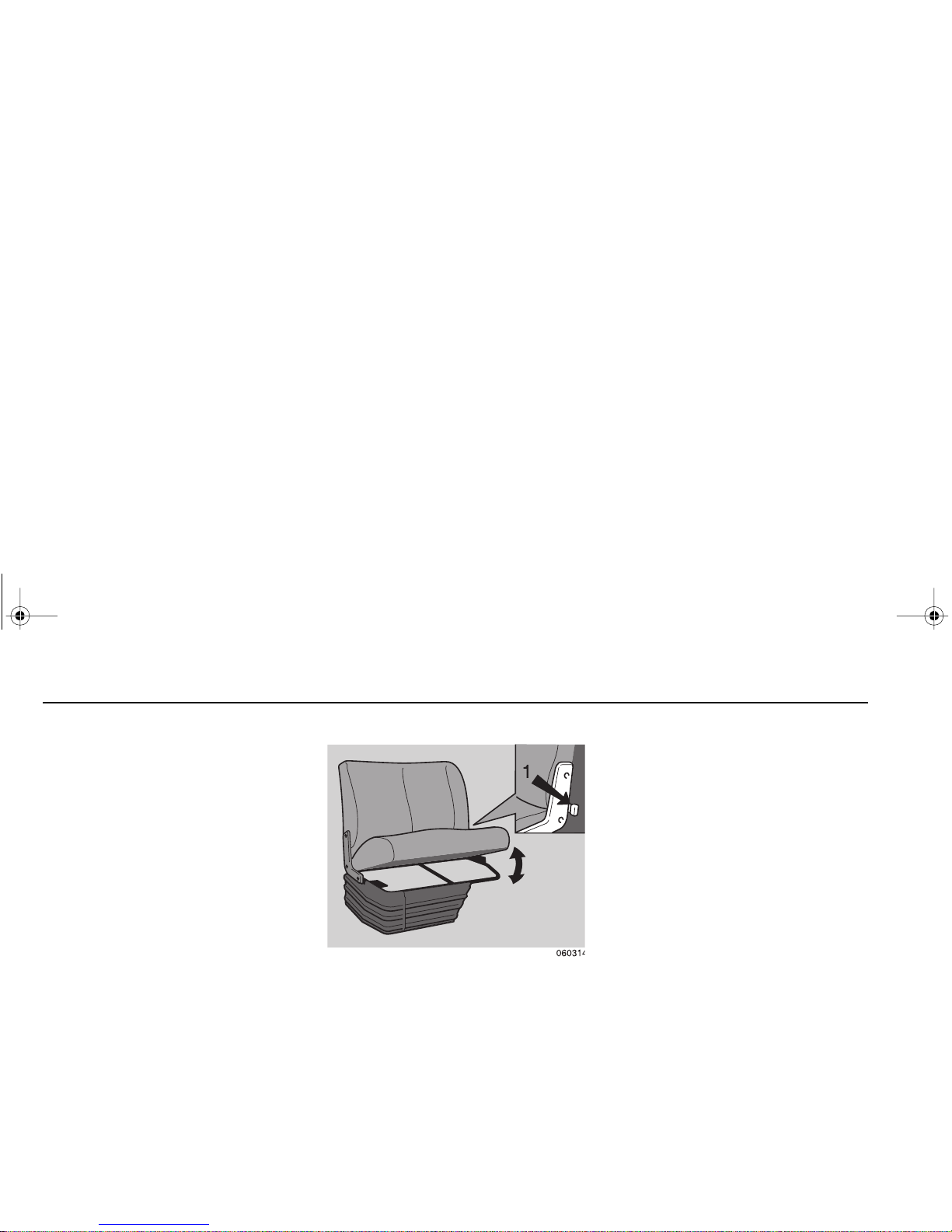
Passenger’s Seat (2-man)
The 2-man passenger seat is fixed and
non-adjustable. A storage compar tment, con taini ng the vehicl e tool kit, is
located beneath the seat cushion. To
gain access to the storage compartment depress the lock cont rol lever 1
and lift the seat cushion. When the seat
cushion is fully upr ight, it will aut omatically lock in position; depress the lock
control lever to release the seat cushion.
Passenger’s Seat (single-adjustable)
The single passenger’s seat can be
adjusted for fore/aft position, seat cushion height, and backrest rake. Refer to
“Driver's Seat (adjustable)”
for the
adjustment procedures.
Seat Belts
The driver’s seat and pa ssenge rs seat
are equipped with seat belts, these
should be w or n by t he se at u ser w hen
the vehicle is in motion.
PB1340A .book Page 18 Friday, Sept ember 1, 2000 7:40 AM
Page 27
Cab Getting to Know Your Vehicle
– 19 –
WARNING! Do not drive
vehicle without your seat
belt and your riders’ belt fastened. Riding without a
safety belt properly fastened
can lead to increased injury
or death in an emergency.
Unbelted riders could be
thrown into the wind shie ld
or other parts of the cab or
coul d be thrown out of t he
cab. They could strike
another p erson . In juries can
be much worse when riders
are unbelted. Always fasten
your seat belt and be sure
anyone riding with you does
the same.
WARNING! Always wear
your seat b el t low over you r
pelvic bones.
• You can be seriously injured if
your belt is buckled too high. In a
crash, it would apply force to
your abdomen, not your pelvic
bones. This can result in serious
internal injuries.
• Do not drive with your seat belt
loose. A too-loose seat belt can
allow you to fall too far forward,
possibly causing head an d ne ck
injuries. You could strike the
whee l or the win dsh iel d. Ad jus t
your belt so that there is no more
than 1 in. (25mm) of slack.
WARNING! Do not wear the
shoulder part of belt und er
your arm or otherwise out of
position. In a crash your
body would move too far forward, increasin g the chan ce
of head and neck injury.
Also, the belt would apply
too much force to the ribs,
which are not as strong as
your shoulde r bones , and
could cause you to suffer
internal injuries. Wear the
shoulder belt over your
shoulder.
WARNING! Do not twist the
belt in the process of putting
it on. A twisted belt will not
work as well to protect you.
In a crash, the full w idth of
the belt would not be protecting you. A twisted belt
could cut into your body and
cause serious injuries.
Straighten t he belt b efore
buckling it. If you are unable
to wear it withou t tw isting it,
have your dealer or service
person replace it as soon as
possible.
Observe the following recommendations:
•Do not use any seat belt for more
than one person.
PB1340A .book Page 19 Friday, Sept ember 1, 2000 7:40 AM
Page 28

Cab Getting to Know Your V ehi cle
– 20 –
• Before securing a seat belt, ensure
that the webbing is not twisted,
looped or obstructed in any way
that co uld impair the operat ing
mechanism.
• Optimal safety can be offered by a
seat be lt only when i t is prop erly
tightened.
• Never have repair s or modifica tions
made to the seat belts.
• Replace the seat belt when the
webbing is worn or damaged.
• If the seat belts have been subjected to high loading during a collision, then the complete assembly
must be replaced, even if there is
no visible evidence of damage.
Seat belt upper anchorage adjustment
The seat belt upper anchorage point
should be adjusted so that the belt webbing crosses m idway betw een th e
user’s neck and the edge of the
shoulder.
To adjust the position of the upper
anchorage point, depress the locking
button a nd, simult aneou sly, slide the
anchorage point to the desired position;
release the locking button when the
required position is obtained.
Seat belt care
• Regularly inspect all seat belt webbing, anchorage points, and locking
mechanisms for correct operation
and for evidence of excessive wear
or damage.
• Check the seat belt locking action
by rapidly pu lli ng t he b el t webb ing
out o f its re trac ting un it; t he belt
webbing must lock, i.e. i t must not
be pulled out of the retracting unit.
•Do not clean the belts with aggres-
sive cleaning agents; if ne cessary,
use an all-purpose cleaner.
PB1340A .book Page 20 Friday, Sept ember 1, 2000 7:40 AM
Page 29
Cab Getting to Know Your Vehicle
– 21 –
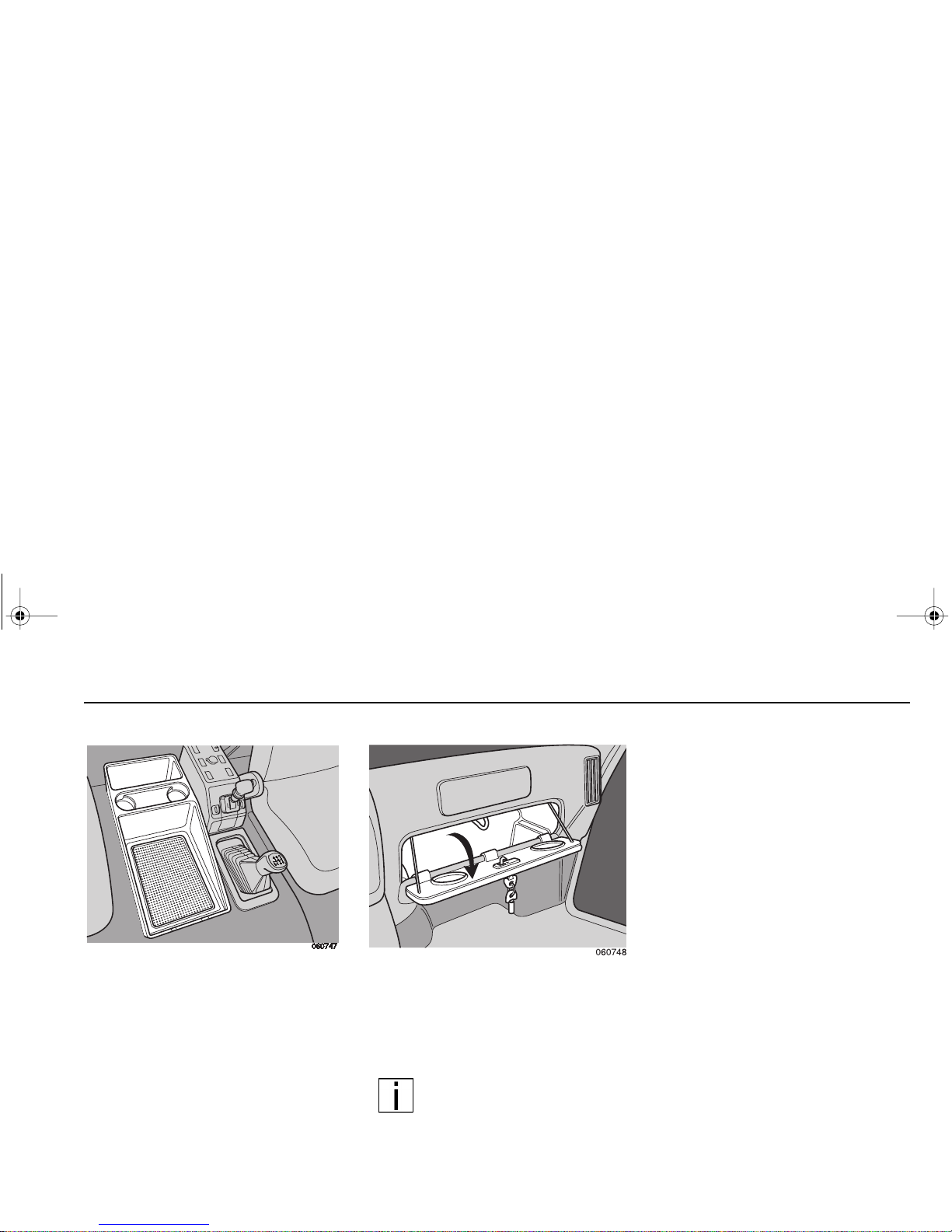
Storage Tray
Your truck ma y be equipped with a fixed
storage tray. The storage tray is of a
pre-formed construction incorporating
storage bins and cup holders.
Glove Box
All vehicles are equipped with a lockable glove box.
NOTE: The “ Operator’s Man-
ual” is stored in the glove box.
Keep this book in the cab at all
times.
PB1340A .book Page 21 Friday, Sept ember 1, 2000 7:40 AM
Page 30
Cab Getting to Know Your V ehi cle
– 22 –
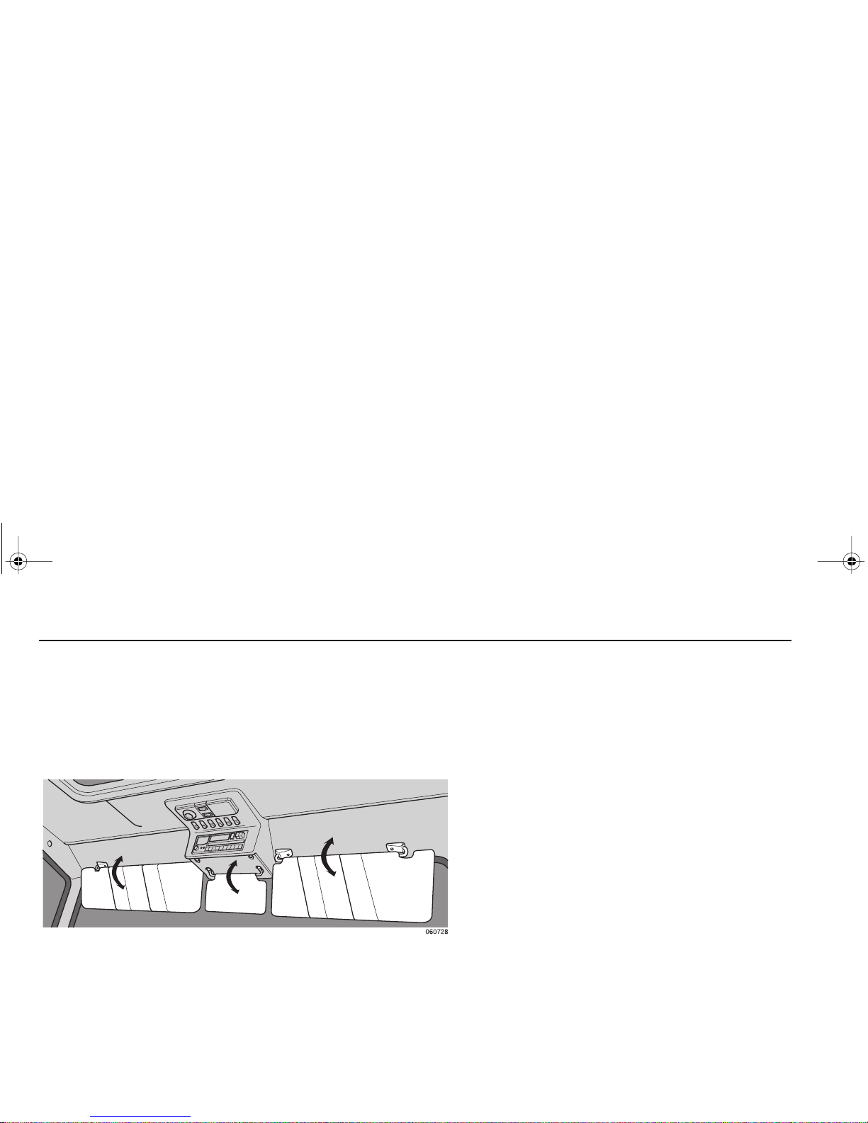
Sun Visors
The cab is fitted with 3 sun visors
which are provided for the driver and
passenger. The sun visors can be
swung down to block the sun.
PB1340A .book Page 22 Friday, Sept ember 1, 2000 7:40 AM
Page 31
Cab Getting to Know Your Vehicle
– 23 –
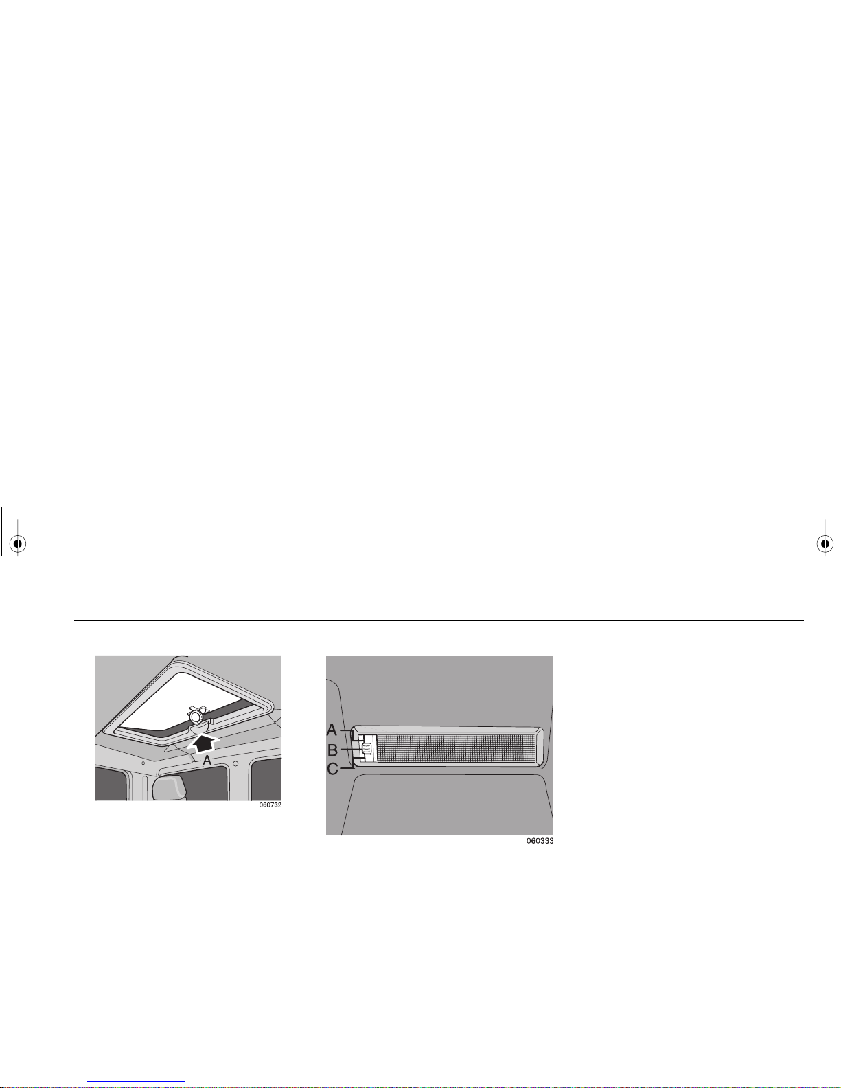
Roof Vent (option)
Rotate the control knob (A) to open and
raise the roof vent to the required position.
Courtesy Lights
All cabs are equipped with two courtesy
lights which are fitted in the cab roof lining above each door.
The court esy light switch has three
positions:
Position A: the lig ht will onl y illumin ate
when the door is opened.
Position B: light is switched off.
Position C: light is on permanently.
PB1340A .book Page 23 Friday, Sept ember 1, 2000 7:40 AM
Page 32

Cab Getting to Know Your V ehi cle
– 24 –
Interior Light Unit
All cabs are equipped with an interior
light unit which is fitted in the c ab center
roof pan el. T he in ter ior l igh t uni t i nco rporates a directable reading light and a
courtesy inter ior light; both lights are
indepen dently ope rated using the interior light mounted switches.
Courtesy interior light
The cour tesy i nterio r light swit ch (1)
has three positions:
Position A: li ght is switched off.
Position B: li ght is switched off.
Position C: li ght is switched on.
Reading light
The reading light is operated by the on/
off swit ch (2); the lig ht beam can be
directed to the required position by
moving the swivel lens.
Ashtray
An ashtray is provided in the center
panel. Raise the cover to open the ashtray. To empty the ashtray, close the
cover and extract the complete a shtray
unit from its holder . Replace the ashtray
by reversing the removal procedure.
Cigarette Lighter
A cigarette lighter is provided in the
center panel adj acent to the asht ray.
Depress the cigarette lighter in its
socket; the cigarette lighter will partially
eject when ready for use.
The cigarette lighter can be used as a
12 volt accessory power supply. Before
connecting electrical equipment to the
A
PB1340A .book Page 24 Friday, Sept ember 1, 2000 7:40 AM
Page 33

Instruments and Controls Getting to Know Your Vehicle
– 25 –
cigarette lighter socket it is essential to
ensure that:
• only 12 volt (negative ground) electrical equipment is connected to the
cigarette lighter power socket.
• the power consumption of any electrical com ponen t does no t exceed
10 amps.
Instrume n ts an d
Controls
General
The instru ments and control s are
located on the instrument panel, center
console, center roof console, and steering column.
Warning Light s
All warning lights are color coded to
indicate the level of their importance.
The color codes and th e required
driver's response are as follows:
Red
Illumination of any red warning light
during normal dr iving conditions indicates a major system or equipment
malfunction. In the event of any red
warning light illuminat ing, the vehicle
must be stopped and the engine
switched off. Do not attempt to drive the
vehicle until the fault has been fixed.
Amber
Illumination of any amber warn ing light
during normal dr iving conditions indicates an eq uipment /system malfu nction. In the event of an amber warning
light i llu min a ting, th e vehic le m ay con-
tinue on its jo urney but ad dition al driving caution must be observed. The fault
should be fixed at the earl iest o ppor t unity.
Green Or Blue
Illumination of any green or blue warning lig ht i nd ica tes t hat a un it/sys te m is
operational.
WARNING! Do not ignore a
warning light or buzz er.
These signa ls may tell you
somethin g is wrong wit h
your vehicle. It could be a
failure in an impor tant system, such as t he brakes,
which coul d lead to an acc ident. Have the appropriate
system checked imm ediately.
PB1340A .book Page 25 Friday, Sept ember 1, 2000 7:40 AM
Page 34

Instruments and Controls Getting to Know Your Vehicle
– 26 –
Instru me nt Panel
A/C
RECIRC
0
75
130
175
250
100
200
0
75
130
175
CRUISE ON/OFF
SET/RESUME
35
34
33
32
31
30
29
28
27
26
25
22
23
24
1
2
3
4
5
6
7
8
9
10
11
12
13
14
15
16
17
18
19
20
21
BRAKE
AIR
PTO
TRANS
TEMP
CHECK
TRANS
CRUISE
CONTROL
DIFF
LOCK
BRAKE
AIR
PTO
TRANS
TEMP
CHECK
TRANS
CRUISE
CONTROL
DIFF
LOCK
PB1340A .book Page 26 Friday, Sept ember 1, 2000 7:40 AM
Page 35

Instruments and Controls Getting to Know Your Vehicle
– 27 –
1. Tachometer
2. PTO warning light
3. High beam warning light
4. Hazard switch warning light
5. Turn signal warning light - vehicle
6. Cruise control warning light
7. Cab-lock warning light
8. Oil pressure warning light
9. Low air pressure warning light
10. Battery charge warning light
11. Parking brake warning light
12. Not used
13. Differential lock warning light
14. ABS warning light
15. Maintenance - Water in Fuel
16. Check engine warning light
17. Stop engine warning light
18. Coolant temperature warning light
19. Wait to Start engine warning light
20. Transmission oil temperature
warning light
21. Check transmission warning light
22. Fuel gauge
23. Coolant temperature gauge
24. A/C On-Off switch
25. Heating and ventilation controls
26. Ventilation fan indicator light
27. Air pressure gauge - (secondary)
28. Fuse box - right
29. Air pressure gauge - (primary)
30. Speedometer/odometer
31. Fuse box - left
32. Vehicle lighting switch
33. Cruise control Set/Resume switch
34. Cruise control On-Off switch
35. Hazard warning light switch
PB1340A .book Page 27 Friday, Sept ember 1, 2000 7:40 AM
Page 36

Instruments and Controls Getting to Know Your Vehicle
– 28 –
Switches, Gauges, and
Warning Lights on the
Instru me nt Panel
1. Tachometer
White field: low-idling speed
Green Field: economical speed range
Yellow field: maximum power range
Red field: excessive/overspeed range
(not permitted)
2. PTO Warning Light
(A PTO is not available from the factory.) This warning light will illuminate
whenever the PTO is engaged.
Do not drive vehicle at highway speeds
if PTO is engaged (light is ON).
3. High Beam Warning Light
This war nin g light w ill illu mina te whe never the headlights are in the high
beam p ositio n or w hen the he adligh t
flash is operated.
4. Hazard Switch Warning Light
This warning light will flash simultaneously in conju nction with both dire ction indicators whenever the hazard
warning light switch is activated.
5. Turn Signal Warning Light - Vehicle
This warning light flashes in conjunction
with the vehicle turn signals.
6. Cruise Control Warning Light
This war nin g light w ill illu mina te whe never the cruise control is switched ON.
7. Cab-lock Warning Light
This warning lig ht wi ll il lu min ate a nd a
warnin g buzzer will so un d if t he c ab is
not correctly locked in the down position; this warning ligh t is on ly operative
while the ignition is switched on. Also
see the
“Cab”
section of this handbook.
Do not attempt to dr ive the vehicle
while this warning light is illuminated.
8. Oil Pressure Warning Light
This warning lig ht wi ll il lu min ate a nd a
warning buzzer will sound when the
engine oil pressure is too low. In the
event of the oil pressure warning light
illuminatin g dur ing nor mal dr ivin g conditions, the vehicle mu st be stopped
and the engine switched off. Do not
attempt to re-start the engine until the
fault has been rectified.
PB1340A .book Page 28 Friday, Sept ember 1, 2000 7:40 AM
Page 37

Instruments and Controls Getting to Know Your Vehicle
– 29 –
WARNING! The air pressure
warning light and the au dible alarm in dica te a dange rous situation: there is not
enough air pressure in the
reservoirs for repeated braking and, except when the
engine is started, indicates
the brake system has failed.
Without the use of your service brakes your spring
brakes could suddenly apply
causing a wheel lock-up,
loss o f c o nt rol, or ove r- take
by following vehicles. You
coul d be in an acci den t and
severely injured.
• Bring the vehicle to a safe stop
right away, while you still have
control of the vehicle. Follow the
procedure below:
Air Loss Emergency Procedure
1. Slow down carefully.
2. Move a safe distance off the road
and stop.
3. Place the transmission in park and
set the parking brake. (See pages
58
and 66 for transmission shifting
and parking brake information.)
4. Tur n OFF the engine.
5. Turn ON the emergency flasher
and use other warning devices to
alert other motorists.
If the li ght an d alar m do no t tur n off at
startup, do not try to drive the vehicle
until the problem is found and fixed.
9. Low Air Pressure Warning Light
This war nin g light w ill ill umin ate an d a
warning buzzer will sound whenever
there is insufficient air pressure (less
than 80 ps i or 5.5 ba r) available in a ny
air reservoir.
Do not attemp t to drive th e vehicle
while this warning light is illuminated.
10. Battery Charge Warning Light
This warning light will illuminate if the
battery cha rg ing voltage falls below 1 1
volts.
11. Parking Brake Warning Light
This war nin g light w ill illu mina te whe never the parking brake is applied or
when there is insufficient air pressure
available to release the parking brake.
12. Blank
This warning light is not used.
13. Differential Lock Warning Light
(A locking differential is not available
from the factory.) This warning light will
illuminate whenever the differential is
locked.
PB1340A .book Page 29 Friday, Sept ember 1, 2000 7:40 AM
Page 38

Instruments and Controls Getting to Know Your Vehicle
– 30 –
14. ABS Warning Light
This war n ing light mo nit ors the vehicle
anti-lock braking syste m (ABS). This
warning light will illuminate when:
• the ignition is switched on; the light
should extinguish as soon as the
vehicle road speed exceeds 5 mph
(7 km/h);
• the vehicle ABS is defective; the
conventional braking will remain
operative but the vehicle must be
driven with care and the ABS must
be rectified at the ear lie st opp or tunity.
Also see
“Driving”
and
“Emergency
repairs”
sections of this handbook.
15. Maintenance - Water in Fuel
This warning light will illuminate if the
water/fuel separator needs to be
drained.
16. Check Engine Light
This warning light will illuminate when
an engine problem exists, but the vehicle can still be sa fely driven. Th e vehicle should b e ser viced to correct the
problem but the situation should not be
considered an emergency.
17. Stop En gi ne Li ght
This warning light will illuminate when a
major eng ine pr oblem exi st s. It me an s
you should stop and shut down your
vehicle as soon as it is safely possible.
NOTE: If you need to determine
the exact engine problem that
turns on warning light 16 or 17,
you must access the on-board diagnostic system. With the key switch ON but
the engin e NOT running, pre ss the
throttle pedal to full throttle and release
to idle th ree times. The active fault
codes will flash out as descr ibed in the
Cummins ISB Engine Operation and
Maintena nce Manual. Contact your
dealer or th e Cumm ins engi ne ser vice
center for t he explana tion of th e code.
Turn the key switch OFF to exit the
diagnostic mode.
18. Coolant Temperature Warning
Light
This warning lig ht wi ll il lu min ate a nd a
warning buzzer will sound whenever
the engine coolant temperature
exceeds the maximum permissible
level.
PB1340A .book Page 30 Friday, Sept ember 1, 2000 7:40 AM
Page 39

Instruments and Controls Getting to Know Your Vehicle
– 31 –
19. Wait to Start Light
This warning light will illuminate when
the air intake h eater is ON. Do not
attempt to start the engine until the light
goes out.
20. T ransmission Oil Temperature
Warning Light
(Functional only if optional Allison automatic transmissi on is installed.) Thi s
warning light will illuminate whenever
the transmission oil temperature
exceeds the maximum permissible
level.
21. Check Transmission Warning
Light
(Functional only if optional Allison automatic transmissi on is installed.) Thi s
warning light will illuminate w hen a
problem exists with the transmission,
but the vehicle can still be safely driven.
The vehicle should be serviced to correct the problem, but the situation
should n ot be consid ered an eme rgency.
22. Fuel Ga ug e
The fuel gauge gives an approximate
indication of the fuel t ank con tents and
only operates with the ignition switched
on.
PB1340A .book Page 31 Friday, Sept ember 1, 2000 7:40 AM
Page 40

Instruments and Controls Getting to Know Your Vehicle
– 32 –
23. Coolant Temperature Gauge
The coolant operating temperature
should be between 165°F (74°C) and
198°F (92°C ). A t a tem perat ure of less
than 140°F (60 °C) the eng ine should
not be fully loaded by the driver. If the
coolant temperature suddenly r ises
and/or the gauge pointer enters the red
field, then the following items should be
checked:
• The coolant level. See “Coolant
Level” on page 51.
• The drive belt and water hoses.
• The operation of the viscous fan
drive.
24. A/C On/Off Switch
(With optional air conditioning only)
This switch turns the air conditioner
compressor and t he rem otely m ounte d
condenser on and off.
25. Heater And Air Conditioner
Controls
WARNING! Do not drive with
your visi bility reduced by
fog, co nden sation, or frost
on the windshield. Your view
may be obscured, which
could result in an injury
250
100
200
A/C
A/C
RECIRC
0
75
130
175
250
100
200
1
2
3
4
PB1340A .book Page 32 Friday, Sept ember 1, 2000 7:40 AM
Page 41
Instruments and Controls Getting to Know Your Vehicle
– 33 –
accident. For clear visibility and safe
driving it is extremely important for
you to follow the ins tru ction s on the
use of the ventilation/heating and
defogging/defrosting system. If in
doubt, consult your dealer. Maximum heating output and fast
defrosting can be obtained only after
the engine has reached operating
temperature.
WARNING! Excessive heat
may cause the pressurized
components of the air conditionin g system to explode.
Never weld, sold er, steam
clean, or use a blow torch
near any par t of the air conditioning system.
• If a refrigerant leak develops in
the presence of excessive heat
or an open flame, hazardous
gases may be generated. These
gases may cause unconsciousness or deat h. If you become
aware of a refrigerant leak on
your vehicle, have your system
serviced immediately and
observe the following precautions:
– Stay away from the hot
engine until the exhaust
manifold has cooled.
– Do not permit any open
flame in the area. Even a
match or a cigarette lighter
may generate a hazardous
quantity of poisonous gas.
– Do not smoke in the area.
Inhaling gas eous refr ig erant
through a cigarette may
cause violent illness.
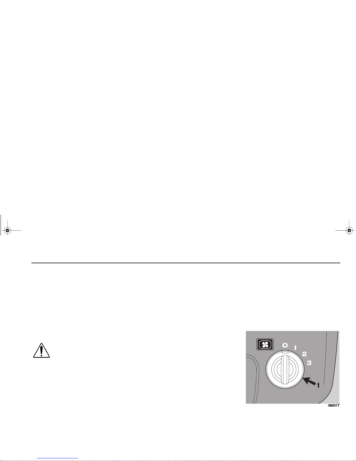
The heating and air conditioner controls
are located on the instrument panel.
The heater and air co nditione r controls
consist of a rot ary switch for regula ting
the bl ower spe ed, a slide c ontrol for
selecting air distribution, a slide control
for selecting air temperature, and with
optional air conditionin g, a push button
switch for turning the ai r conditioning on
or off.
22. Ventilation Fan Indicator Light
When illu minated , indica tes th e blower
switch is on (Positions 1-3).
Rotar y switch (1) Contro ls the blower
speed (3 speeds and an off position).
PB1340A .book Page 33 Friday, Sept ember 1, 2000 7:40 AM
Page 42

Instruments and Controls Getting to Know Your Vehicle
– 34 –
Slide control (2) Controls the air distribution within the cab.
A bi-level mode exists when the slide
control is placed between Windshield
and Floor position s or between Floor
and Panel (Fresh) positions.
The optional air conditioner compressor
is engaged when the control is placed
in Windshield mode (top-most position).
Slide control 3. Controls progressive
adjustment of the heater from 0 to
100% output.
Air vents and defoggers
The heater and air conditioner system
has fixed and adjustable air vents for
windshield defogging, heating or cooling the interior of the cab, defogging the
door glass, and heating or cooling the
footwell area.
The center panel has two air vents,
adjustable for direction and volume of
air flow.
= Windshield
= Floor
= Panel (Fresh)
= Panel (Recirc)
RECIRC
RECIRC
RECIRCRECIRC
PB1340A .book Page 34 Friday, Sept ember 1, 2000 7:40 AM
Page 43
Instruments and Controls Getting to Know Your Vehicle
– 35 –
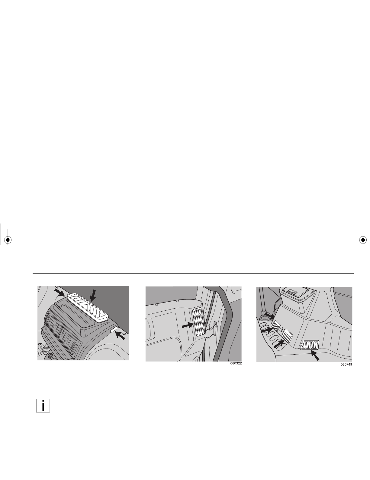
The center panel incorp orate s a cen -
tral defogger with two integral side
vents for defogging the entire width of
the windshield.
NOTE: The ce ntral defogg er
outlet is fitted with a prote ctive
mesh to prevent the entry of
foreign objects. To maintain
maximum air flow efficiency, do
not place objects on the protective mesh or obstruct the
central defogger in any way.
Two fixed air outlets at the left and right
of the cab fascia are directed at the
door glass. These vents and outlets
admit heated or cooled air into the cab.
In the footwell area there are four outlets which are no t adjus table for dire ction of the air flow. These vents and
outlet s admi t hea ted or cool ed ai r into
the cab.
PB1340A .book Page 35 Friday, Sept ember 1, 2000 7:40 AM
Page 44

Getting to Know Your Vehicle Instruments and Controls
– 36 –
NOTE: Fo r the r em aind er of
the Heating section, numbers
in parentheses ( ) refer to
items shown in this figure .
A/C
RECIRC
0
75
130
175
250
100
200
060752
1
2
3
4
Heating
To heat the cab: select the desired air distribution (2) and temperature (3) to hot (red
position on the control). Adjust the fan speed (1) as desired.
CAUTION: During extreme cold weather, do not blow hot air onto cold
windshields. This could crack the glass. Turn the air direction lever to
Defrost and adjust the fan speed accordingly while the engine warms.
If the engine is already war m, m ove the temperatur e selector to Coo l,
then gradua lly in crease the tem perat ure w hen you see th at the wind shield is starting to warm up.
HEATING A/C CONTROL
CONTROL S
HEATING COOLING DEFOGGING
MAX NML MAX NML MAX NML
Fan Speed (1) High Adjust High Adjust High Adjust
Air Dist ribution
(2) Panel
Panel
or Bi-
Level
Recirc Adjust
Windshield
Wind-
shield or
Bi-Level
Temperature (3) Warm Adjust Cool Adjust W arm Adjust
Air Conditioner -
AC (4)
OFF OFF ON ON ——
PB1340A .book Page 36 Friday, Sept ember 1, 2000 7:40 AM
Page 45

Instruments and Controls Getting to Know Your Vehicle
– 37 –
Defogging
NOTE: If equipped with
optional air conditioning, the
air conditioning system is
active when the Defrost mode
is selected.
To defog the windshi eld: sele ct air dis tribution to Windshield or between
Windshield/Floor and turn the fan
speed switch (1) to high. Set the temperature control (3 ) to ho t (red position
on the control). The air conditioner (if
equipped ) is automat ically acti vated to
remove moisture from the cab. After the
windshi eld is cl ear, adjust the co ntrol s
as desired.
Cooling
To cool the cab: turn on the air conditioner (if equipped) (switch 4), set the
temperature control (3) to cool (blue
side), and the fan (1) to high until the
cab becomes cool—adjust as desired.
When set to Recirc mode, the air condi-
tioning system will automatically shut
off fresh air intake and will recirculate
cab air.
For Efficient Cooling:
1. Ensure all heater/air conditioner
controls are off.
2. Start the engine. Allow time for
warm–up.
NOTE: A cold compressor can
cause refrigerant to liquefy and
warp the valve plates or cause
a hydraulic lock. Warm the
engine before starting the air
conditioner.
3. Set the ai r condi tioner for maximum
cooling.
4. Close all windows.
5. Idle the engine between 1,000 and
1,500 rpm and turn the fan switch
to High.
6. After the cab temperature cools to
a comfortable level, adjust the fan
speed and other controls to keep
the desired condition.
7. For efficient air flow in fresh air
mode, regularly clean the HVAC filter located on the bottom of the
cab. First, place the system in
“recirc” mode and then clean the filter with a low pressure air hose.
• If the air conditioner does not cool
the air, have the unit checked at an
Authorized Service Center.
NOTE: When the air conditioner isn’t i n regular use, operate it for at least 15 minutes at
least once a month or every
5,000 miles (8,000 km), whichever
comes first. This will lubricate the seals
in the air conditioning system.
PB1340A .book Page 37 Friday, Sept ember 1, 2000 7:40 AM
Page 46

Instruments and Controls Getting to Know Your Vehicle
– 38 –
27. Air Pressure Gauge “Sec ondary”
Air gauge “2” constantly monitors the
air pressure in the rear brake reservoir.
At reservoir air pressures below 80 psi
(5.5 bar) a warning buzzer will sound
and a warning light, mounted in the
instr ume nt panel , will il lumin ate; th e
warning buzzer and warning light are
only operative while the ignition is
switched on. Do not attempt to drive
the vehicle with less tha n 80 ps i (5.5
bar) of air pressure.
28. Fuse Box - Right
To gain access to th e circ uit and spar e
fuses, rotate the quick release fastener
(1) using a coin and then slide the fuse
cover downward. To enable the fuses to
be easily removed, a fuse extraction
tool (2) is attached to the inside of the
fuse cover. Also see the
“Emerg ency
repairs”
section of this handbook.
29. Air Pressure Gauge “Primary”
Air gauge “1” constantly monitors the
air pressure in the front brake reservoir.
At reservoir air pressu res below 8 0 ps i
(5.5 bar) a warning buzzer will sound
and a warning light, mounted in the
instrument panel, will illuminate; the
warning buzzer and warning light are
only operative when the ignition is
switched on. Do not attempt to dr ive
the vehicle with le ss than 80 psi ( 5.5
bar) air pressure.
060751
0
75
130
175
060751
0
75
130
175
PB1340A .book Page 38 Friday, Sept ember 1, 2000 7:40 AM
Page 47

Instruments and Controls Getting to Know Your Vehicle
– 39 –
30. Speedometer/Odometer
The speedome ter indic ates the vehicle
speed in miles per hour (MPH) and in
kilometers per hour (kph)
The odomete r records the d istance
trav eled by the vehicl e, either in miles or
kilometer s, depen di ng on wh ich u nit i s
installed in the vehicle.
31. Fuse Box - Left
To gain access to the circuit and spare
fuses, rotate the quick release fastener
(1) using a coin and then slide the fuse
cover downward. To enable the fuses to
be easi ly removed, a fu se extracti on
tool (2) is attached to the inside of the
fuse cover. Also see the
“Emergency
repairs”
section of this handbook.
32. Vehicle Lighting Switch
The vehicle lig hting is op erated by a
rotary type switch with three positions:
km/hkm/h
mphmph
milesmiles
1010
2020
3030
4040
5050
5555
6060
7070
8080
2020
4040
6060
8080
100100
120120
lighting switched off
side lights, instrument
panel, and cab marker
lights
headlights, side lights,
instrument panel, and
cab marker lights
PB1340A .book Page 39 Friday, Sept ember 1, 2000 7:40 AM
Page 48
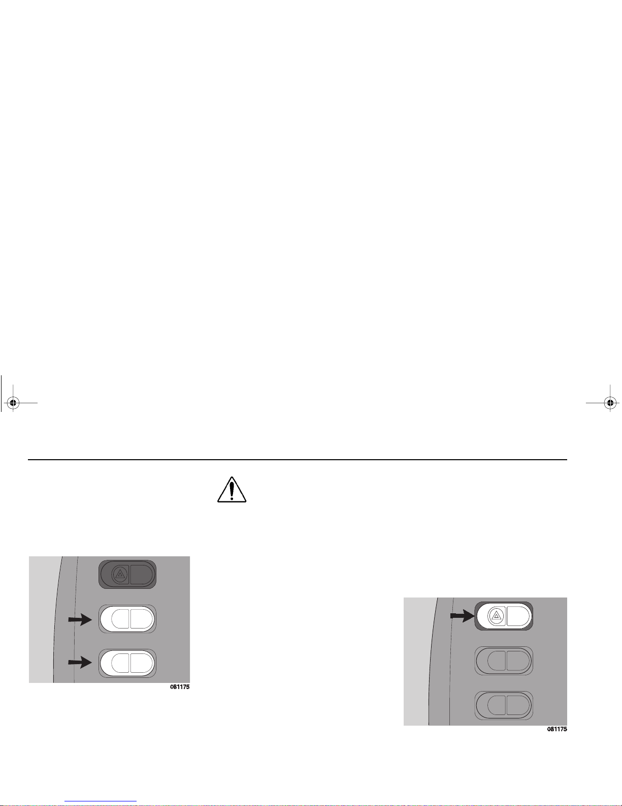
Instruments and Controls Getting to Know Your Vehicle
– 40 –
33. Cruise Control Set/Resume
Switch
This switch allows the desired speed to
be set or resumed after the cruise control function is turned on or interrupted.
34. C r uise Control On /Off Switch
This switch turns the cru ise control
function ON or OFF.
WARNING! Do not operat e
the c ruise cont rol when
operati ng on road surf aces
with p oor tract io n (w et , icy,
or snow covered roads) or
in heavy traffic. Accelerations cause d by t he no rmal
operation of the cruise control could cause you to lose
control of the vehicle
resulting in an injury accident.
35. Hazard Warning Light Switch
Activating this rocker type switch
causes al l the turn sig nals to flash
simultaneously; a warning light on the
instrument pa nel wi ll illuminate w hile
the hazard lights are working. Return
the rocker switch to its off positio n to
cancel the hazard lights.
CRUISE ON/OFF
SET/RESUME
A
CRUISE ON/OFF
SET/RESUME
PB1340A .book Page 40 Friday, Sept ember 1, 2000 7:40 AM
Page 49

Instruments and Controls Getting to Know Your Vehicle
– 41 –
OPERATING LEVER, PARKING
BRAKE
This lever i s used to ac tuate the parking
brake. Also see the
“Driving”
section of
this handbook.
WARNING! Never drive your
vehicle with the parking
brake applied. Always
release the parki ng br akes
prior to moving the vehicle.
Failure to disengage the
parking brakes prior to moving your vehicle could result
in excessive heat build-up in
the brake system, resulting
in a fire.
NOTE: Today’s diesel electronic engines have significant
torque and startability power at
low RPM. Combinations of
engine speed and available
torque may over-power the
vehicle’s parking brakes.
PB1340A .book Page 41 Friday, Sept ember 1, 2000 7:40 AM
Page 50

Instruments and Controls Getting to Know Your Vehicle
– 42 –
CENTER ROOF CONSOLE
B
NOTE: Optional radio shown
PB1340A .book Page 42 Friday, Sept ember 1, 2000 7:40 AM
Page 51

Instruments and Controls Getting to Know Your Vehicle
– 43 –
Interior Light
The interior light unit incorporates a
directable read ing light an d a cour tesy
interior light; both lights are independently operated using the interior light
unit mounted switches. Refer to the
“Cab” section of this handbook for the
interior light unit operating procedures.
Mirror Heating Switch
The door mirror heating can be activated with this switch. When the door
mirror heating is on, the switch warning
light will illuminate.
CAUTION: The mirror heating must be swit ched on
only for the period of time
required to clear moisture from the
mirror glass; excessive use may
damage the mirror and th e heating
element.
Instrument Panel Lighting Switch
The instrument panel w ill automatically
illuminate whe n t he li ghts are switche d
on. The intensity of the instrument
panel il lumi nation ca n be inc reased by
activating this rocker switch. Return the
rocker switch to its off position to revert
to low level illumination.
NOTE: Optional radio shown
on this page
A
A
B
PB1340A .book Page 43 Friday, Sept ember 1, 2000 7:40 AM
Page 52

Instruments and Controls Getting to Know Your Vehicle
– 44 –
Controls Arou nd The Steering Col um n
SET/RESUME
A/C
RECIRC
km/h
mph
miles
10
20
30
40
50
55
60
70
80
20
40
60
80
100
120
CRUISEON/OFF
PB1340A .book Page 44 Friday, Sept ember 1, 2000 7:40 AM
Page 53
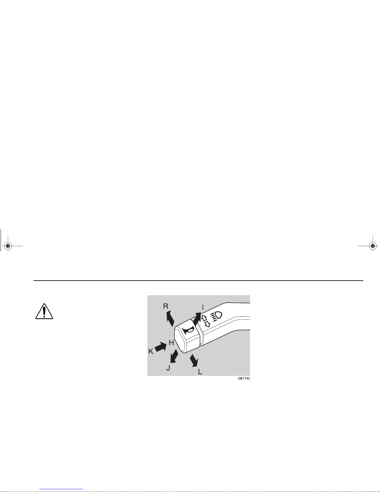
Instruments and Controls Getting to Know Your Vehicle
– 45 –
Adjustable Steering Column
WARNING! Do not adjust the
steering column while the
vehicle is in mot ion, it co uld
cause loss of control. You
would not be able to steer
properly and could have an
accid ent. Make all ad justments to th e steering column while the vehicle is
stopped.
Loosen the lo cking control a nd move
the steering w he el forward or r earward
to the required position; ensure that the
locking control is tightened and that the
steering column is locked in posit ion
before attempting to drive the vehicle.
Multi-func t io n Sw itc h, Left
Headlight flash, low beam, high
beam
Position H: rest position.
Position I: lift against spring pressure =
headlight flash.
Position J: position for switching
between low beam or high beam.
The lever al ways re tur ns to pos itio n H
when it is released.
Turn Signals
The lane -chang e m ode of th e turn signals is operated by keeping the lever
pushed in against spring pressure. The
turn sig nal s wo r k only w ith the ig ni tio n
switched on.
Position L:
turn signals, left
Position H:
rest position
Position R:
turn signals, right
Horn
The ho rn works w hen button K is
pushed in against spring pressure.
PB1340A .book Page 45 Friday, Sept ember 1, 2000 7:40 AM
Page 54

Chassis Getting to Know Your Vehicle
– 46 –
Multi-funct ion Switch, Right
Windshield wipers
Position A:
wipers off.
Position B:
wipers on, normal speed.
Position C:
wipers on, high speed.
Position D:
single wipe and intermittent
wipe function
Momentarily depress the switch (up to
½ sec.) and the n release to ob tain a
single wipe of the windshield. Depress
the switch for between ½ to 1½ secs to
activate the intermittent wipe function;
depress the switch for ½ to 1½ secs t o
cancel the intermittent wipe mode.
NOTE: A single wipe can be
carried out between interm ittent wipes withou t cancelling
the intermittent wipe cycle.
The windshield wipers work only with
the ignition switched on.
Windshield washers
The windshield washers are activated
by depressing button (E) against spring
pressure.
The wipers simul tan eous ly m ake th ree
sweeps across the windshield.
Chassis
Towing Pin
The front bumper incorporates a towing
pin which can be fitted to the left or right
side of the bumper and is suitable f or all
norm al towing. Refer to the “
Emer-
gency Rep airs
” section of this handbook for the recommended towing
procedures.
PB1340A .book Page 46 Friday, Sept ember 1, 2000 7:40 AM
Page 55

Daily and Weekly Maintenance
– 47 –
DAILY AND WEEKLY MAINTENANCE
Driver’s Check List
To keep your truck in top shape and
mainta in a h igh level of s afety for you,
your passengers, an d your load, make
a thorough inspection every day before
you drive. You will save maintenance
time later, and the safety ch ecks could
help prevent a serious accident. Please
remember, too, that the Federal law
requires a pre-trip inspection per Federal Motor Carrier Safety Regulation
392.7 and so do commercial tr ucking
companies.
You are not expected to become a professional mechanic. The purpose of
your inspections is to find anything that
might interfere with the safe and efficient transportation of yourself, any
passengers, and your load. If you do
find something wrong and cannot fix it
yourself, have an Authorized S ervice
Center or qualified mechanic repair
your vehicle right away.
The following operations are to be performed by the d r iver. Performing the se
checks and follow ing th e main tenan ce
procedure s in this manual will h elp
keep your truck running properly.
Approaching Your Vehicle
• Check the overall appearance and
cond ition. Are wi ndows, mi rrors,
and lights clean and unobstructed?
• Check beneath the vehicle. Are
there signs of fuel, oil, or w ater
leaks?
• Check for da maged, loose , or missing par ts. Are th ere pa rt s showing
signs of excess ive wear or lack o f
lubrication? Have a qualified
mechanic examine any q uestionable items and repair them witho ut
delay.
• Check your load. Is i t secur ed properly?
Daily Checks
Engine Compartment
1. Engine Fluid Levels—add more if
necessary.
• Engine oil
• Coolant (check while engine is
cold)
• Power steering fluid level
PB1340A .book Page 47 Friday, Sept ember 1, 2000 7:40 AM
Page 56

Daily and Weekly Maintenance
– 48 –
2. Engine Belt—check tension and
condition of belts per engine manufacturer’s Operation and Maintenance Manual.
• Measure the belt tension at the
longest span of the belt.
• If cracks, breaks or tears are
found in any belt, the belt
should be replaced before
operating the vehicle.
Air conditioner compressor belt
(with opt ional air conditio ning only) The best method of testing belt tension
is to apply a good quality commercial
gauge. If a tension gauge is not available, use this method of testing:
• Apply 25 pounds (111 N.) of force
midway between the pulleys.
• Deflection should be one belt thickness for each foot distance
between the pulley centers.
Retensioning New Belts
A belt is cons idered “us ed” after 30 minutes of operation. After running for an
hour or more, new belts will loosen.
Check for proper tension after the first
period of operation. If the belt can be
deflecte d 1/8 in. (3 mm) more tha n
specified, tighten according to the
instructions above.
CAUTION: Do no t tighten
belts beyond specified limits. Damage to bearings
and belts may occur.
3. Fuel Filter/Water Separator Draining—check and drain. Depending
on th e fu el s tor age facili ty, more
frequent draining may be required.
4. Windshield washer reservoir fluid
level—fill if necessary.
Chassis and Cab
Before entering the cab and operating
the veh ic le, check th e foll owin g e qu ip ment for proper maintenance:
1. Lights—do headlights, turn signals,
emergency flashers, and exterior
lamps function and are they clean
and adjusted properly?
2. Windows and Mirrors—are they
clean and adjusted properly?
Tension Test
02953
PB1340A .book Page 48 Friday, Sept ember 1, 2000 7:40 AM
Page 57

Daily and Weekly Maintenance
– 49 –
3. Tires and Wheels—are they
inflated properly? Are all wheel cap
nuts in place and torqued properly—tighten if necessar y. Check
front wh eel bearing oil levels.
Inspect all tires and wheels for
damage—correct if found.
4. Suspension—check for loose or
missing fast ener s. Check da ma ge
to springs or other suspension
parts.
5. Brake Components—check lines,
linkages, c hambe rs, pa rkin g and
service brake operation.
6. Air System—are there leaks?
• Air Tanks—drain water from all
air tank s. Make sure th e drain
cocks are closed.
7. Steps and Handholds—check for
worn surfaces and loose or missing
fasteners.
8. Fluid Tanks—check underneath
the vehicle f or signs of flui d leaks . If
any are found, correct before operating the vehicle.
9. Fuel Tank Caps—are they secure?
WARNING! Diesel fuel in
the presence of an ignition source (such as a
cigarette) could cause
an explos ion. You coul d
be seriously injured. A
mixture of gasoline or
alcohol with diesel f uel
increases this risk of
explosion.
• Do not remove a fuel tank
cap near an open flame.
• Use only the fuel and/or
additives recommended for
your engine.
Cab Interior
1. Seat—adjust the seat for easy
reach of controls.
2. Seat Belts—fasten and adjust
safety restraint belts.
3. Steering Column—adjust for easy
reach.
4. Mirrors—check and readjust mirrors if necessary.
5. Lights—turn ignition key to the ON
position and check for warning
lights and buzzer. Check operation
of turn signals and emergency
lights.
6. Instruments—check all instruments.
7. Windshield—check operation of
windshield wipers and washers.
8. Horn—check operation of horn.
PB1340A .book Page 49 Friday, Sept ember 1, 2000 7:40 AM
Page 58

Daily Maintenance Daily and Weekly Maintenance
– 50 –
9. Storage Compartment—all loose
items stowed securely. Is the fire
extinguisher fully charged? Is your
road emergency kit complete?
Compartments closed?
10. Fuel—check fuel. Is there enough
fuel?
NOTE: The above items
(Engine Compartment, Chassis and Cab, and Prestart
Checks) should be checked
daily, as a m inim um. T hey ar e
in additi on to, not in pla ce of
Federal Mot or Carrie r Safety
Regula tions. The se regulations may be purchased by
writing to:
Superintendent of Documents
U.S. Government Printing Office
Washington, DC 20402
Daily Maintenan ce
Front Access Panel
To O pen
The hinged front panel can be unlocked
by pushing the release control sideways. The front acce ss panel can the n
be swung up and secured in position
with the support stay.
To Close
To close the front access panel, releas e
and stow the support stay and lo w er the
front panel into position. Gently push
each lower corner of the front access
panel un til the in ternal locks ar e he ard
to engage.
Engine Oil Level
1. The vehicle must be parked on flat
and level ground.
2. Pull the dipstick (1) out of the dipstick tube and wipe it clean with a
lint-free cloth.
3. Place the dipstick completely back
in the dipstick tube.
4. Withdraw the dipstick again and
check the oil level; the oi l level
should always be bet ween t he two
marks on the dipstick.
PB1340A .book Page 50 Friday, Sept ember 1, 2000 7:40 AM
Page 59
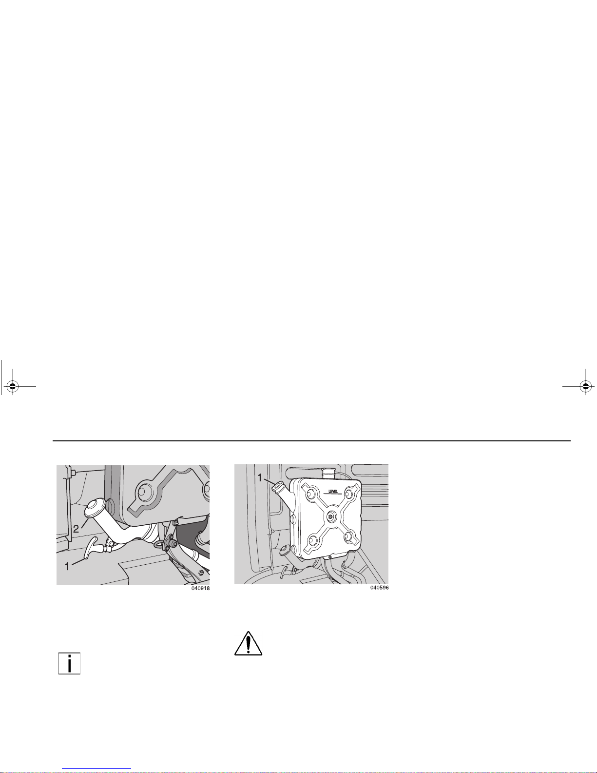
Daily and Weekly Maintenance Daily Maintenance
– 51 –
5. If necessary, add oil through the
filler opening ( 2). A lways use oil of
the same brand and grade. Never
overfill with oil!
NOTE: Difference between the
MAX and MIN marks on the
dipstick is approximately 1 3/4
quarts (2 liters).
Coolant Level
WARNING! Do not attempt to
remove the surge tank filler
cap while the engine is running or still hot. The com-
plete co oling system is
under pressure in these conditions.
Scalding steam and fluid under pressure may e scap e and caus e s er ious
injuries . You could be b adly bur ne d.
Before attempting to check the coolant level, ensure that the following
safety instructions are observed:
– Do not fill the cooling sys-
tem thro ugh the pres sure
cap aperture.
– Do not attempt to fill a hot
engine with cold coolant.
– Anti-freeze solutions con-
tain t oxic chemi cal s wh ich
must not be consumed or
allowed to come in to skin
contact. Use impervious protective clothing an d gloves
when handling antifreeze. In
the event of slight skin contact, thoroughly rinse the
affected area with water. If
there is ex ce ss iv e sk in c on tact, ing est io n, or i nha latio n
seek medical advice immediately.
PB1340A .book Page 51 Friday, Sept ember 1, 2000 7:40 AM
Page 60

Daily Maintenance Daily and Weekly Maintenance
– 52 –
1. Remov e the filler cap (1) and check
that the engine coolant is level with
the lower lip of the filler neck; if necessary, fill the surge tank with
approved coolant.
CAUTION: The use of unapproved coolants ca n cause
severe damage to the cooling system an d it s c omp onents. Should the cooling
system require an excessive
amount of coo lant , the co mplete system must be
inspec ted for leaks and
repaired (consult your
dealer).
Wheels And Tires
Remove any stones or other foreign
objects from the tire tread and from
between the tires (axles fitted with dual
wheels).
• Check for evidence of wear and
damage and for nails or other foreign objects embedded in the tires.
• Check the wheel lug nuts.
• Check the tire pressures. Do this
while the tires are cold.
Lighting And Instruments
• Check the vehicle lighting, stoplights, and instruments for correct
operation.
• Also check the operation of the
horn, windshield wipers, and washers.
Driver’s Seat And Mirrors
• Adjust the seat and mirrors to the
correct position.
PB1340A .book Page 52 Friday, Sept ember 1, 2000 7:40 AM
Page 61
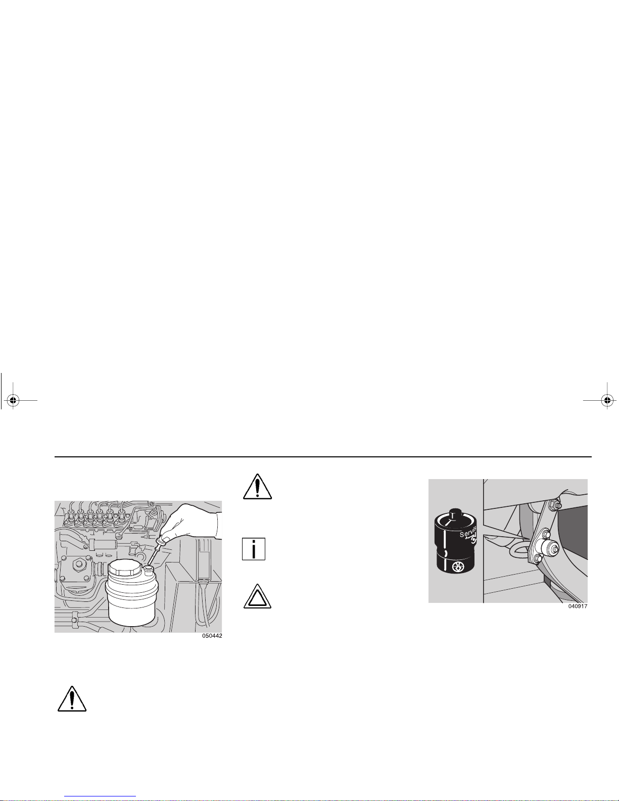
Daily and Weekly Maintenance Weekly maintenance
– 53 –
Weekly maintenance
Power Steering Fluid Level
WARNING! Hydraulic fluid is
a toxic substance which
must not be co nsumed or
allowed to com e into skin
contact.
WARNING! Ensure that the
parking brake is on or all
wheels are chocked prior to
inspecting the power steering fluid level.
NOTE: Suitable wheel chocks
are at a minimum an 18-inch
(46 cm) long 4x4.
CAUTION: Do not operate
the vehicle if the power
steering fluid level is low.
1. Thoroughly clean the area around
the dipstick.
2. Check the fl uid level in the reservoir
with the dipstick.
3. With the engine running, the fluid
level should be u p to the upper
mark (MAX) on the dipstick. With
the engine switched off the fluid
level is approximately 3/4 inch
(2 cm) higher.
Air Filter Restriction
Indicator
The air induction syst em is equipped
with a vacuum operated restriction indicator. The air filter elem ent mus t be
replaced whenever the restriction indicator has been activated; this is indicated by the appearance of a redcolored plunger within the indicato r
body. For furthe r infor matio n con tact
your dealer.
PB1340A .book Page 53 Friday, Sept ember 1, 2000 7:40 AM
Page 62
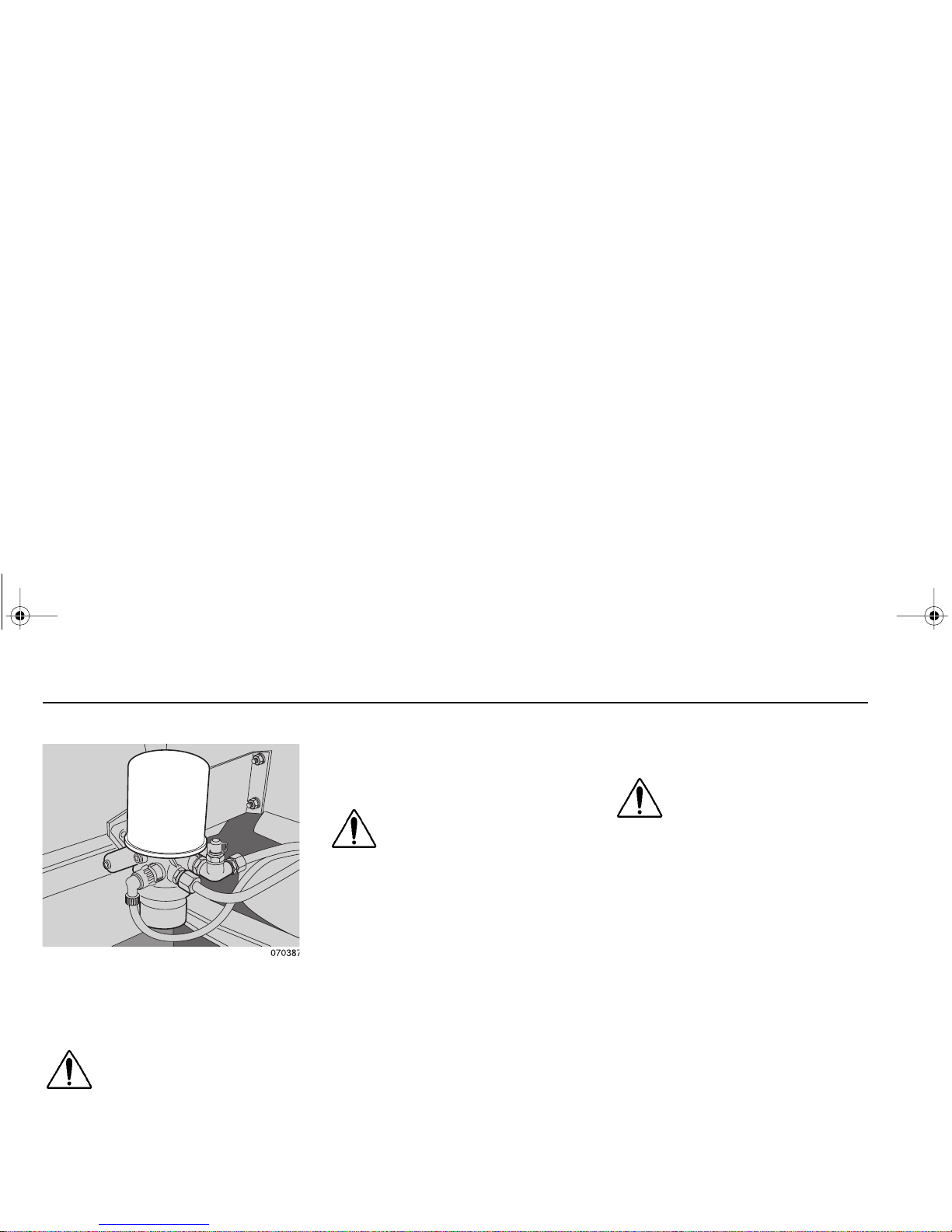
Weekly maintenance Daily and Weekly Maintenance
– 54 –
Brake System Air Dryer
(optional equipment)
WARNING! Do not operate
the veh icle in the eve nt o f a
malfunction in any ai r circuit. Such a malfunction may prevent the brake system from
operati ng p roperly, and could r e sult
in an injury accident. The vehicle
should not be operated until the sys-
tem is repaired and both braking circuits, including all pneumatic and
mechanical components, are working properly.
WARNING! Ensure that the
following safety instructions are strictly observed:
• Fully charged air reservoirs contain air at an approximate pressure of 120 psi (8.4 bar). It is
essential that su itable eye protection and protective gloves are
worn wh ile releasi ng the air
pressure from the reservoirs.
• The air dryer and filter cartridg e
contain pressurized air at the
brake system op erating pressure. Do not puncture nor
attempt to remove the filter cartridge.
1. Chock the road wheels and fully
charge the vehicle air system.
WARNING! If the supply a nd
service tanks are not
drained at the recommended
frequency, water could enter the air
lines and valves. This cou ld cause
corrosion or blockage, which could
compromise the brake system safety
and potentially caus e an inju ry accident.
2. Pull each air reservoir drain valve
ring and check that the expelled air
is free of any condensate (water/
oil/particles); should any condensate be observed from any air reservoir consult your dealer.
PB1340A .book Page 54 Friday, Sept ember 1, 2000 7:40 AM
Page 63
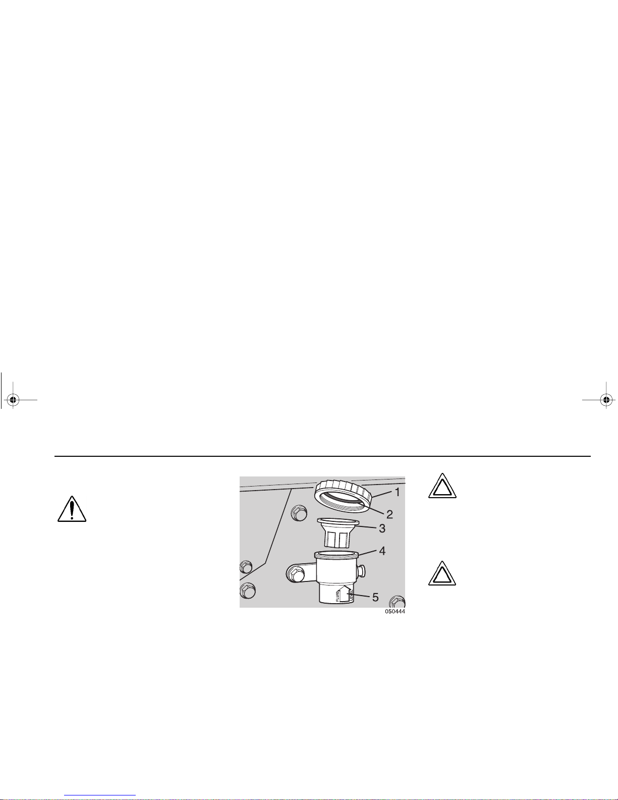
Daily and Weekly Maintenance Weekly maintenance
– 55 –
Clutch Fluid Level
WARNING! Hydraulic fluid is
a toxic substance which
must not be co nsumed or
allowed to com e into skin
contact.
1. Open the cab front panel to gain
access to the clutch reservoir.
2. Check that the hydraulic fluid level
registers on or above the level
mark (5), molded on the clutch reservoir; if necessary, fill the fluid
level as follows:
– Remove the reservoir cap (1)
and extract the rubber diaphragm (3) from the reservoir
(4).
– Fill the reservoir with clean
hydraulic fluid of th e app roved
specification (DOT 3 brake
fluid).
– Insert the rubber diaphragm
into the reservoir.
– To prevent leakage from the
reser voir, ens ur e th at t he seal
(2) in the reser voir cap is in
good condition before refitting
the cap.
CAUTION: Should the clu tch
fluid reservoir require an
excessive amount of
hydraulic fluid, the complete
system must be inspected
for leaks and repaired if necessary (consult your dealer).
CAUTION: Do not allow th e
clutch hydraulic fluid to contact pai nt f in ishe d sur faces .
It could damage the paint.
PB1340A .book Page 55 Friday, Sept ember 1, 2000 7:40 AM
Page 64

Weekly maintenance Daily and Weekly Maintenance
– 56 –
Windshield Washer Fluid
Level
1. Open the cab front panel to access
the reservoir filler tube.
2. Remove the filler cap and refill the
reservoir with a suitable windshield
cleaning solution.
NOTE: During the winter
period, it is re co mm en de d t ha t
a suitable solutio n with antifreeze protection is used.
Tires
• Check the tread depth of the tires.
• Check that the wear pattern is
evenly distributed over the ru nning
surface of each tire.
PB1340A .book Page 56 Friday, Sept ember 1, 2000 7:40 AM
Page 65

General Driving
– 57 –
DRIVING
General
Before starting the engine o r setting
out on a trip, always check:
• The vehicle for water, fuel, or oil
leaks.
• The seat and mirrors for correct
positioning.
• The operation of the lights and
instruments.
• That the vehicle load is correctly
secured.
After each trip always check that:
• The doors of the vehicle are locked.
• The load is still properly secured.
Ignition Switch
WARNING! Do NOT remove
the key from the steering
lock/ignition and starter
switch while the vehicle is in motio n
because this may cause the steering
wheel lock to engage.
Position A: rest position
The key can be removed.
When the key is removed from the
switch, the steering wheel is locked.
Position B: accessories position
Steering wheel unlocked.
The key cannot be removed. Access ories, such as a radio, can be switched
on.
Position C: ON position
All power consumers can be switched
on.
Position D: starting
When the key is released, it automatically returns to position C.
PB1340A .book Page 57 Friday, Sept ember 1, 2000 7:40 AM
Page 66

Starting Procedure Driving
– 58 –
Starting Procedure
WARNING! Ensure that the
following safety instructions are strictly observed:
– Do not start the engine in a
confined space or unventilated area. Exhaust fumes
contain toxic gases which, if
inhaled, can prove fatal.
– Before driving away, ensure
that all warning lights h ave
been ext inguis hed an d the
warning buzzer has ceased
to sound.
CAUTION: When the engine
starts and runs, do not allow
the engine to exceed its
idling speed for 10 seconds;
this procedure will ensure
that adequate oil p ressure is available at the turbocharger bearings.
1. Ensure that the parking brake is
applied an d the shif t lever is in the
neutral position.
2. Tur n ignition key to position ‘C’ and
check that the oil pressu re and
parking brake warning lights illuminate and that the fuel gauge shows
sufficient fuel for the trip.
3. If the engine WAIT light is on, wait
until it goes out.
4. With the accelerator pedal
releas ed, turn the ign ition key t o
position D; release the key immediately after the engine has started. If
the engine fails to start after 10
seconds, release the key. Wait 10
seconds and repeat the starting
procedure.
Operating the
Transmission
Introduction
Your is equipped with either a manual,
automatic, or aut omated manua l transmission with special features and gearing to me et your pa r t icu lar n ee ds. I t i s
impor t an t for yo u, t he dr iver, t o un de r stand how your pa r ticul ar tran smission
is operated.
In addition to the instructions listed in
this
Operator’s Manual,
additional
instructions a nd guid elines ar e available in the transmission manufacturer’s
Driver/Operator ’s Instr uc tion M anu al
in
your glovebox. Read the general guidelines and instruct ions that follow and
PB1340A .book Page 58 Friday, Sept ember 1, 2000 7:40 AM
Page 67

Operating the T ransmission Driving
– 59 –
read the specific instructions contained
in the transmission manufacturer’s
Driver/Operator’s Instruction Manual
.
Operating Manual
Transmissions
If your truck has an automatic transmission, go to page 62
.
If your truck h as an au tom ated manua l
transmission, such as the Eaton® Autoshift™, go to page 63
.
Your transmis sion has six forward gears
with full synchromesh engagement,
and one reverse gear. Yo u will find a
shift pattern diagram on the gearshift
knob. Make sure you follow the cor rect
sequence for shi fting y our tr ans missi on.
Transmission Warm–Up
In cold weather [below 32°F (0°C)], you
may find shifting sluggis h when you first
start up. Transmission warm-up is
especially important at this time, but it is
always a good idea to warm your transmission oil before startin g out on the
road.
To warm the transmission lubricating oil
during engine warm-up:
1. Put the transmission in Neutral.
2. Release the clutch pedal and let
the transmission operate in Neutral
for three to five minutes prior to
shifting into either a forward or
reverse range.
Putting the Vehicle in Motion
WARNING! Never drive your
vehicle with the parking
brake applied. Always
releas e the parkin g brakes
prior to moving the vehicle.
Failure to disengage th e
parking brakes prior to moving your vehicle could result
in excessive heat build-up in
the brake system, resulting
in a fire.
NOTE: Today’s dies el elec tronic engines have significant
torque and startability power at
low RPM. Combinations of
engine speed a nd available
torque may over-power the
vehicle’s parking brakes.
PB1340A .book Page 59 Friday, Sept ember 1, 2000 7:40 AM
Page 68

Operating the Transmission Drivin g
– 60 –
CAUTION: Always us e first
gear or a low speed range to
start the veh icle in mo tion.
The use of a higher gear or
speed range forces undue
strain o n th e e ngine , clut ch,
other transmission components, and may cause damage.
After ma king sure the ve hicle’s oil a nd
air pressure a re correct a nd all other
par ts and sy stems are in prop er wor king condition:
1. Fully depress the clutch pedal and
shift the transmission into first gear.
2. Lift the sleeve on the parking brake
handle and push the han dle fully
forward to release the brakes.
3. Release the clutch pedal, then
gradually accelerate.
4. Do not allow your vehicle to roll
(even a little) in the opposite direction during clutch engagem ent. If
you need to star t up on a n incline,
apply your ser vice b rakes before
you release the parking brake.
Then release your service brakes
as you engage the clutch and apply
throttle.
For further instructions on operating
your transmission, see the transmi ssion
manufacturer’s
Driver/Operator’s
Instruction Manual
.
If you have a misaligned gear condition
in your vehicle’s transmission and cannot start, gradually release the clutch,
allowing t he dr ive ge ar t ee th t o l ine u p
properly. Then the dr ive gear can roll
enough to allow the teeth to line up
properly and complete the shift.
The best engine performance and maximum economy is obtained if gears are
properly selected. This efficiency is
achieved by always selecting gears
within optim um engine rpm, whic h is
where maximum to rqu e and p ower are
obtained.
Shifting Gears in a New Vehicle
Shift carefully in a new vehicle. The
transmission may be a little stiff at first.
Avoid gear clashing by closely following
these procedures.
When you are o pe rati ng a new vehicle
or one that has been exposed to cold
weather, you want the transmission
lubricant (fluid) to circulate and coat the
contacting surfaces of the gears. Meta l
contacting metal in moving parts may
seriously damage your transmission—
do not drive in one gear f or long periods
of time until the transmission lubricant
has a chance to coat all contacting surfaces.
PB1340A .book Page 60 Friday, Sept ember 1, 2000 7:40 AM
Page 69

Operating the T ransmission Driving
– 61 –
WARNING! Do not coast
with the transmission in
neutral or with the clutch
pedal depressed—it is a
dangerous practice. W ithout the use of the retarding
power of the drivet rain, your
vehicle can reach dangerous
speeds. At very high speeds
you may no t be able to p ut
the transmission in any gear.
At high speeds you could
seriously damage your vehicle or cau se an acci dent
whe n yo u pu t th e tr an smis sion in gear. The engine
speed co uld exceed the
maximum governed speed
and cause a serious accident due to m echan ical failures.
More Transmission Tips
“Riding” the Clutch
The clutch is not a footrest. DO NOT
DRIVE WITH YOUR FOOT RESTING
ON THE CLUTCH PEDAL. It will allow
your clutch to slip, causing excessive
heat and wear—damage could result.
Release Bearing Wear
When you must idle your engine for any
period of time, shift y our tr ans mission to
Neutral and dise ngage th e clutch (t ake
your foot OFF of the pedal) . Th is helps
prevent unnecessary wear to your
clutch release bearing, and it is less tiring for you, too.
Clutch Adjustment
If your truck has an Eaton® Solo clutch,
no adjustments are necessary . This is a
self-adjusting clutch and requires no
adjustments for wear.
Inspect manual clutches according to
the maintenance and lubrication intervals in this manual. Regular maintenance must be followed to maintain
correct clutch ad justment . Have your
dealer’s Service Depar tment perfor m
any adjustment necessary.
Tips for Manual Transmission
Operation
• Always use the clutch when making
upshifts or downshifts.
• Always start in first gear.
• Never downshift when the vehicle
is moving too fast.
PB1340A .book Page 61 Friday, Sept ember 1, 2000 7:40 AM
Page 70

Operating the Transmission Drivin g
– 62 –
• Never slam or jerk the shift lever to
complete gear engagement.
• Never coast with the transmission
in Neutral and the clutch disengaged.
• To provide smooth gear engagements while shifting, use proper
coordination between shift lever
and clutch.
Operating Automatic
Transmissions
An automatic transmission makes shifting much easier, of course. But
because your truck pulls a heavy load,
it is important to use it efficiently. For
correct automatic transmission operation, also see the transmission manufacturer's
Operator’s Manual.
• On most automatic transmissions
there is no “PAR K” position, so you
will need to apply the parking brake
before leaving the cab. See page
66.
WARNING! Do not leave the
cab without app lying the
parking br ake. The truck
could roll and cause an
injury accident . Always
apply the parking brake
before you leave the cab.
The MD Automatic Transmission
The MD (electronic) Series of transmissions have four, five, or six forward
speeds, a Neutral position, and one
reverse speed. Pressing the appropriate button selects the desired gear.
Vehicles equipped with the MD transmissions have various diagnostic features. Refer to the transmission
manufacturer’s
Operator’s Manual
for
information on all diagnostic features.
MD Automati c Transmission - Elect ronic
Shift Selector
01916
PB1340A .book Page 62 Friday, Sept ember 1, 2000 7:40 AM
Page 71

Operating the T ransmission Driving
– 63 –
The MD transmission is programmed to
restrict full operation until specific temperatures are reached. See the trans-
missi on manu facture r’s
Operator’s
Manual
for details.
Operating Automated
Manual Transmissions
The Eaton® Autoshift™ transmission is
an automated manual transmission.
The Autoshift™ is a partially automated
Eaton
®
Fuller® Roadranger® transmis-
sion that automatica lly selects and
engages the transmission’s gears. The
driver mu st use th e cl utch t o s tart and
stop the vehicle, but not for shifting
through the gears. A shift begins when
the Autoshift™ computer detects that
conditio ns are r ight for a shift. T he
transmission signals the engine contr oller to brea k driveline torque an d provides engine RPM for synchroniz i ng the
next gear. When engine speed and
gear speed are synchronized the transmission engages the next gear and signals the eng ine to resume operation.
Please see the transmission
Operator’s
Manual
for fur ther d eta ils o n the tra ns-
mission’s operation and components.
WARNING! Do not leave the
cab without applying t he
parking brake. The truck
could roll and cause an
injury accident. Always
apply the park ing brake
before you leave the cab.
Eaton® Autoshift™ Trans mission -
Electronic Shif t Sel ector
PB1340A .book Page 63 Friday, Sept ember 1, 2000 7:40 AM
Page 72

Operating the Transmission Drivin g
– 64 –
Cruise Control
This feature improves fuel mileage and
reduces driver fatigue by maintaining a
constant vehicle speed. The cruise
control will only operate above a programmed minimum vehicle speed of 30
mph for the Cummins ISB engine.
Engaging the Cruise Control
NOTE: Ensure that the vehicle speed is above the minimum cruise control speed
and the engine speed is
above 1100 rpm.
1. Mov e the ON/OFF s wit ch to the ON
position.
NOTE: Toggling the SET/
RESUME switch to the
RESUME position at this
point will select the previously
set cruise speed.
2. Accelerate the vehicle to the
desired cruise speed.
3. Toggle the SET/RESUME switch
to the SET position to set the c ruise
speed.
•To decrease the cr uise set speed,
hold the SET /RESUM E swi tch i n
the SET position and coast to a
lower speed.
•To increase the cruise set speed,
hold th e SET /RESU ME switch in
the RESUME position; this will
accelerate the vehicle to a higher
speed.
Disengaging the Cruise Control
Do one of these steps to disengage the
cruise control:
• Move the ON/OFF switch to the
OFF position.
or
• Depress the brake pedal.
or
• Depress the clutch pedal.
CRUISE ON/OFF
SET/RESUME
A
PB1340A .book Page 64 Friday, Sept ember 1, 2000 7:40 AM
Page 73

Steering Driving
– 65 –
Reengaging the Cruise Control
1. Mov e the ON/OFF s witch to the ON
position.
or
2. Toggle the SET/RESUME switch to
the RESUME position.
Steering
The steering gear is hydraulically
assisted. As excessive pressure may
damage the hydraulic pum p, stop tur ning the steering wheel when the wheels
are at full lock or are blocked by an
obstacle. Steering is also possible without power assistance, but th is r equire s
considerable effort.
Brakes
Anti-Lock Braking System (ABS)
Your truck is equipped with an anti-lock
braking system (ABS). The ABS
reduces the possibility of wheel lock - up .
If a w hee l i s a bou t to lo ck dur ing b raking, the ABS will automatic ally adjust air
pressure to the brake chambers on the
appropriate wheel(s) to prevent wheel
lock-up. The ABS is automatically
turned on w hen the ignition switch is
turned on.
WARNING! Do not rely on an
anti-lock brake system that
is functio ning imprope rly.
You could lose control of the
vehicle result ing in a sever e
accident and personal
injury. If your ABS lamp
goes on while you are driving or stays on after the selfcheck, your anti-lock system
might not be working. The
ABS may not function in an
emergency. You will still
have conventional brakes,
but not anti-lock brakes. If
the lamp indicates a problem, have the ABS checked.
CAUTION: It is essential that
the following driving procedures are observed:
– Do not abuse the ABS sys-
tem by exce ssive ly h ars h or
delayed applicatio ns of th e
service brakes.
PB1340A .book Page 65 Friday, Sept ember 1, 2000 7:40 AM
Page 74
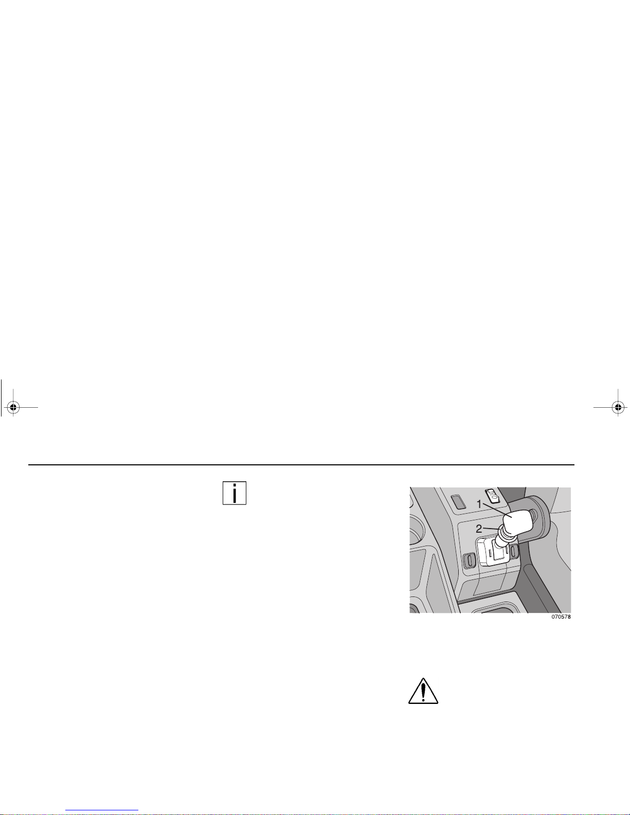
Brakes Driving
– 66 –
– Do not adapt your normal
drivi ng st yle wh en dri ving a
vehicle equipped with ABS.
It is essential that the braking system is operated in a
safe and conventional manner.
– ABS does not shorten the
overall vehicle braking
(stopping) distance.
– In the event of an ABS mal-
function, the ABS w ill be
automatically disengaged
and the ABS warning light
will illuminate. The conventional brak ing system w ill
remain operative, but the
vehicle must be driven with
care and the fault repaired
as soon as possible.
NOTE: The operation and
function of the ABS warning
lights are detailed in the
“Instruments and controls”
section of this handbook.
Service brakes
The service brakes are operated by the
footbrake pedal. If the vehicle has been
driven through water or subjected to
high pressure washing, full braking
power may not be available; dry the
brakes by lightly applying the brakes
while the vehicle is in motion.
If ther e is a mal func tio n in t he ser v ice
brake system, the parking brake can be
used for emergency braking; do not
continue a trip w ith a faulty service
brake system.
Parki ng br ake / emer gen cy
brake
WARNING! Do not attempt to
release the parking brake
while the steering lock is
engaged; failure to observe
this preca uti on can result in
vehicle moveme nt with the
loss of steering control.
PB1340A .book Page 66 Friday, Sept ember 1, 2000 7:40 AM
Page 75
Brakes Driving
– 67 –
The parking brake control operates the
spring brake actuators to apply the rear
brakes on the vehicle.
Move the control lever (1) fully rearward
to apply the parking brakes; a locking
sleeve (2) will lock the control lever in
position . To release th e par king br ake,
lift the locking s lee v e and mo v e the control lever fully forward to the off position.
A red warning light in the inst rument
panel will illuminate whenever the park-
ing brake is applied; refer to the “
Instru-
ments and controls
” section of thi s
handbook.
In the event of a failure in the service
brakes, the par king b rake can b e used
as an emergency brake. Gradually
move the par king brake cont rol lever
rearward to slo wl y appl y the rear brak es
on the vehicle. B raking effor t will be
proportion al t o t he c ontr o l l ever m ovement.
WARNING! Do not drive this
vehicle with malfunctioning
brakes. If one of the brake
circuits should become
inoperativ e, braking distan ces will
increase substantially and handling
character istics wh ile braking will be
affected. You could lose control of
your ve hicle , b e seve re ly in ju re d, o r
caus e an ac ci de nt. Have i t towe d t o
the nearest dealer o r quali fied workshop for repair.
Engine Exhaust Brake
(option)
An engine exhaust brake may be
installed (as an option) to create a braking effect on the drive wh eels. This
device uses your engine's power to
slow your vehicle down. Because it can
help keep your vehicle's brakes from
overheating, it can save wear and tear
on the service brakes. However, the
engine exhaust brake is not an emergency brake.
Ideally ( on no rma l road su rfaces ), you
should slow your vehicle with the
engine exhaust brake (where perm itted
by law) and use the service brakes only
for stopping co mp let ely. Operating th is
way will greatly prolong the life of the
service brakes.
WARNING! The service
brakes must be used in an
emergency. The engine
exhaust brake alone might
not stop you fast enough to
prevent an acciden t. You
could be badly hurt if you
relied only on the engine
exhaust brake.
• The engine exhaust brake is NOT
intended as the primary brake
for the vehicle, nor is it an emergency brake. The engine
PB1340A .book Page 67 Friday, Sept ember 1, 2000 7:40 AM
Page 76

Brakes Driving
– 68 –
exhaust brake only helps the
service brakes by using pressure to slow the drivetrain. Use
the serv ice brakes for qui ck
stops.
Exhaust Brake Operation
With the exhaust brake switch ON, the
engine exhaust brake automatically
creates its bra king effect when you
remove your foot from the accelerator
pedal a nd all ot her req uir ed conditi ons
are met (see below).
The brake switch is located on the
switch panel between the seats. It controls whether the brake is ON (ready to
slow the vehicle down) or OFF (no braking action).
• Make sure the exhaust brake
switch is OFF before star ting the
engine.
• After the engine is started, warmed
up, and you are ready to get under
way, turn the exhaust brake switch
ON for added braking effect.
The engine exhaust brake activates if
all
of the following conditions are true:
• 0% throttle
• Clutch pedal is not depressed
• PTO and cruise control are inactive
• Engine speed is greater than 1000
rpm
WARNING! Do not use the
engine exhaust brake when
operating on road surfaces
with po or tr act ion (such as
wet, icy, or snow covered
roads or gravel). The
engine exhaust brake can
cause the wheels to skid on
a slippery surface. You
could lose control of the
vehicle and/or jackknife if
the wheels begin to skid,
resulting in an accident.
Your vehicle is equipped with Rockwell/
WABCO anti-loc k brak es ( ABS) and the
operation of the engine exhaust brake
(if tur ned ON ) will be contr olled by the
ABS. For more AB S inform ation, see
“
Anti-Lock Braking System (ABS)” on
page 65.
PB1340A .book Page 68 Friday, Sept ember 1, 2000 7:40 AM
Page 77

Stopping Driving
– 69 –
Stopping
Parking
When the vehicle is parked on a grade,
one or mo re of the followin g precau tions should also be taken:
• Chock the wheels at front and rear.
NOTE: Suitable wheel chocks
are at a minimum an 18-inch
(46 cm) long 4x4.
• Angle the front wheels so that the
vehicle will not move into the traffic
stream if it is accidentally set in
motion.
Appl y the par king brake w ith th e park ing brake lever. Check that all th e windows and the roof vent are closed. Turn
off the ignition and remove the key.
Then lock all the doors of the vehicle.
Turning off the engine
WARNING! Do not remove
the ignition key nor turn off
the engine while the vehicle
is in motion. Failure to
observe t his p recau ti on c an
result in steering lock
engagement.
With the vehicle stationa ry, apply the
parki ng brake and pla ce the sh ift lever
in Neutral. Before stopping the eng ine,
allow it to idle for one to two minutes.
This will allow the following:
• An adequate oil supply to the turbocharger bearings while the turbocharger rotor assembly is cooling
preventing the possibility of turbocharger bearing failure.
• Prevention of excessive engine
coolant temperatures.
Turn the en gine of f by tur ning th e ignition key to the OFF position. Then
remove the key.
PB1340A .book Page 69 Friday, Sept ember 1, 2000 7:40 AM
Page 78

Diesel Fuel Drivin g
– 70 –
Diesel Fuel
Cold Weather
Recommendations
When diesel fuel is subjected to low
temperatures (below 21 °F or -6°C), paraffin wax par ticulates will form within
the fuel which will eventually create
blockages in the fuel system. To minimize the risk of f uel
‘waxing’,
it is rec ommended that the following
precautions are observed:
• The use of winter grade fuel will
give added pr otecti on to the fue l
system during cold we ather conditions. Ensure that the vehicle is
using winter grade fu el i n an ticip ation of cold weather conditions.
• In the event of the fuel waxing, it is
recommended that a replacement
fuel filte r is carried to enable a
blocked filter to be replaced; wax
particulates cannot be dissolved by
the application of heat.
• For extreme and prolonged cold
weather conditions, it is recommended that the vehicle be
equipped with a h eated fuel filter
and that all fuel pipes and fuel
tanks are adequately insulated;
refer to your dealer for further information.
PB1340A .book Page 70 Friday, Sept ember 1, 2000 7:40 AM
Page 79

General Periodical maintenance
– 71 –
PERIODICAL MAINTENANCE
General
The dur ability, safety, trade-in value,
and relia bilit y of your veh icle larg ely
depends on the care you give it. This
includes regular servicing in accordance with the maintenance schedules
specified here.
The drivin g style of the crew membe rs
and how they care for the vehicle have
a direct influence on the c ondition of the
vehicle. The driver can frequently give
the dealer information which is very
important for correct maintenance.
The maintenance intervals stated in the
Maintenance Sched ule are bas ed on
the oil specifications stated in “
Recommended Lubrication Types” on
page 86.
PB1340A .book Page 71 Friday, Sept ember 1, 2000 7:40 AM
Page 80

General Periodical maintenance
– 72 –
Maintenance and Lubrication
Intervals
Table 1, ”Recommended Maintenance
Intervals”, shows service intervals for
normal pick-up and delivery operations.
For all other applications, se e your
dealer for intervals.
NOTE: Different lubricants or
service intervals than those
listed below may be required.
Table 1 Recommended Maintenance Intervals
ITEM
MILEAGE INTERVAL (miles)
/TIME INTERVAL (Which-
ever Occu rs Fir st)
COMMENTS
Engine Lubricating Oil
-Check Fluid Level
See Engine Manufacturer’s Specifications and Recommendations
-Change Oil, Oil Filter Per Engine Manufact urer’s Specifications and Recommendations
Clutch Inspect an d Adjust Per
Manufacturer’s Specifications
7500 / 3 mos
w/ Eaton SAS 1401 Clutch
Clutch Release Bearing 7500 / 3 mos
Clutch Cross Shaft 7500 / 3 mos
Drivelines:
City appli c at i on s #
7500 / 3 mos
Grease Yokes and Slip Splines if lubrication zerks are
provided
On-Highway applications## 15,000 / 3 mos
Grease Yokes and Slip Splines if lubrication zerks are
provided
PB1340A .book Page 72 Friday, Sept ember 1, 2000 7:40 AM
Page 81

General Periodical maintenance
– 73 –
HVAC Filter Inspect and Clean as
necessary per this manual 7500 / 3 mos
Clean the filter regularly with low pressure air. See
page 37
.
Replace HVAC Filter Annually
Inspec t Front Axle Fluid Level * 7500 / 3 mos
Inspect Transmission Fluid Level *
7500 / 3 mos
Inspec t Flu id Le v el per Ma n ufacturer ’s Recomm en ded
Procedures
Inspec t Rear Axle Fluid Level *
7500 / 3 mos
Inspec t Flu id Le v el per Ma n ufacturer ’s Recomm en ded
Procedures
Inspect all Brake Components,
replace per Manufacturers Recommendations
7500 / 3 mos
Inspect Engine Air Filter
7500 / 3 mos
Have Filter Element Clea ned, as required via Restric-
tion Indicator, at a Certified PACC AR Dealership,
Replace Filter Element Annually
Front and Rear Brake Camshafts 15,000 / 6 mos
Front and Rear Brake Autoslack
Adjusters
15,000 / 6 mos
Front Axle Kingpins, Tie Rod Ends 15,000 / 6 mos
Replace Pow er St ee ri ng F l ui d and
Filter
15,000 / 6 mos
T wice Yearly ( After Summer and Winter )
Steering Column Shaft U-joint 15,000 / 6 mos
Table 1 Recommended Maintenance Intervals
ITEM
MILEAGE INTERV AL (miles)
/TIME INTERVAL (Which-
ever Occu rs Firs t)
COMMENTS
PB1340A .book Page 73 Friday, Sept ember 1, 2000 7:40 AM
Page 82

General Periodical maintenance
– 74 –
Steering Shaft Telescopic Slide
Surfaces
15,000 / 6 mos
Door Hinges, Latches, and Striker
Plate
15,000 / 6 mos
Test Coolant for Freeze Point and
Nitrite Levels with 2-Way Test
Strip
15,000 / 6 mos
Maintain as Indicated by Test Strip
Replace Coolant annually
Front Axle Fluid Replace * Perform at brake lining
replacement
Per Manufacturer’s Specif ications and Recommendations
Inspect and Adjust Per TMC
RP618 Guidelines
-Front Wheel Bearings 30,000 / Annually
-Rear Wheel Bearings 30,000 / Annually
Lock Cylinders 30,000 or As Required
Door W eatherstrip 30,00 0 or As Requi red
Transmission Fluid Replace * 250,000 / 3 yrs
Rear Ax le Fluid Replace * 250,000 / 3 yrs
# City applications are defined as all applications that require a minimum of 90% of operation time within c ity limits.
## On-Highway applications are defined as all applications requiring less than 10% of operating time on gravel, dirt or unpaved
roads.
* Use only synthetic fluid Per Manufacturers Spec ifications and Recommendati ons
Table 1 Recommended Maintenance Intervals
ITEM
MILEAGE INTERVAL (miles)
/TIME INTERVAL (Which-
ever Occu rs Fir st)
COMMENTS
PB1340A .book Page 74 Friday, Sept ember 1, 2000 7:40 AM
Page 83

General Periodical maintenance
– 75 –
Maintenance Schedule
Use Table 2, ”Maintenance Schedule,”
as a guide to pl an service work. B e sure
and follow the frequency recommendations for you r vehicle. Als o refer to
engine manufacturer’s maintenance
guidelines.
TABLE KEY
NOTE: If a scheduled service interval is s haded, s kip to the
next interval..
I Inspect and Service as required
R Replace
G2 Synthetic Lube Required
Table 2 Maintenance Schedule
INTERVAL COMMENTS
OPERAT ION \ FREQUENCY
7,500 m i
12 000 km
15,000 mi
24 000 km
30,000 mi
48 000 km
60,000 mi
96 000 km
INITIAL DRIVE–IN A B C D
Clutch Inspect and Adjust per mfr’s instructions I
Glass for Cracks or Chips I
Door Window Operation
I
Radio
I
Interior Lights
I Replace As Required
Interior Appearance / Condition: Check For Tears, Stains, Wear
Seats I
Floor Mats I
Door Panels I
Headliner I
Dash I
Covers I
PB1340A .book Page 75 Friday, Sept ember 1, 2000 7:40 AM
Page 84

General Periodical maintenance
– 76 –
Wiper Operation I
Wiper Blade Condition I Replace As Required
Horns (Electric and Air) - Operation I
Mirrors - Cracks or Mounting I
SAFETY EQUIPMENT A B C D
Drain Water from Air Tanks I
Air Tank Check Valve
I
Emergency Operation of Spring Brakes I
Air Press. Build–up time:
I
Governed Air Pressure:
I
Air Press. Drop–Brakes not Applied: ___
I
Air Press. Drop–Brakes Applied: ___
I
Fire Extinguisher Charge
I
Replace or Recharge Per Extinguisher Manufacturer
Recommendation
Flare Kit / Reflectors
I
CIRCLE INSPECTION A B C D
Physical Damage:
Exterior Sheet Metal I
Grille and Radiator I
Air Lines I
Headlights – High and Low Beams I
Road Lights I
Marker Lights I
Turn Signals I
Emergency Flasher I
Brake Lights I
Backup/Loading Lights I
License Plates: Permits and Mounting I
Mud Flaps / Serviceable I
Fuel Tank Mounting I Check Fastener Torque And Condition Of Rubber Lining
Exhaust System–Condition and Mounting Bolts I Leaks / Corrosion
Table 2 Maintenance Schedule
PB1340A .book Page 76 Friday, Sept ember 1, 2000 7:40 AM
Page 85

General Periodical maintenance
– 77 –
Frame F astener Torque: I
Cab: Hold–down Latches
I
Mounts
I
Front Pivot Assembly
I
Jack Operation and Leaks
I
ENGINE SERVICE A B C D
Cooling: Test Coolant for Freeze Point and Nitrite
Level w/2-way Test Strip
I
Maintain Coolant as Indicated by Test Strips
Replace Coolant Annually
Coolant Level I
Coolant Protection:
_______ degrees
I
Pressu re Test
Check At Time Of Coolant Replacement
Hose Condition and Connections
I Leaks And Cracking
Radiator Mounting
I Check Rubber Bushings
Fan Shroud
I Check For Damage
Fan Assembly and Idler Pulley
I Check For Cracks, Chips; Check Belt Tensioner Bearing
Check Water Pump for Leaks / Play
I
Radiator – Exterior Condition
I
Air Cleaner:
I
Replace Annually / Air Cleaner Restriction: Replace If Restriction Indicator displays service required
Contaminant Accumulation
Check Every 7,500 Miles (12,000 km) In Dirty Conditions
Vacuator Val ve–Operation & Condition
I
Mounting Bolts and Clamps
I
Interference
I
Power Steering Fluid and Filter– Replace R Service 2 Times Per Year (after summer and winter)
Drive Belt Condition and Adjustment
I Per Engine Manufacturer’s recommendations
Air Conditioner Compressor Mounting
I
Cold Start Aids
I
High Idle: ________ rpm
I
Emergency Shutdown
I
Vibration Damper Condition
I
Table 2 Maintenance Schedule
PB1340A .book Page 77 Friday, Sept ember 1, 2000 7:40 AM
Page 86

General Periodical maintenance
– 78 –
Drain Water from Fuel System I Per Engine Manufacturer Requirements
Engine Oil – Change
Per Engine Manufacturer Requirements
Oil Filters – Replace
Per Engine Manufacturer Requirements
Fuel Filters – Replace
R
Cranking System:
Visual Inspect./Loose Connecti ons I
Alternator/Charging System:
Visual Inspection/Loos e Connecti ons I
UNDER VEHICLE A B C D
Steering Components – Condition: I
Steering Gear
I
Steering Shaft Splines and Joint(s) I
Pitman Arm
I
Drag Link
I
Steering Arms
I
Tie Rod Arms
I
Tie Rod Ends
I
Radius Rods / Torque Arms
I
Chassis Frame – Cracks or Breaks
I
Spring Shackles and Hanger Brackets
I Check For Cracks Check Fastener Torque
Spring Pins I
King Pin Wear I Per Manufacturer’s Specification
Steer Axle Wheel Bearing End Play Inspection
I
With LMS Outer Ends 350,000 Miles
• No Leak – No Service
Front Hub Lubricant Level I
Spring Leaves
I
U–Bolt and Suspension Fastener Torque
I
Tighten U-bolts after the first 500 miles (800 km). Rear suspension fasteners: retorque after first 2,000 miles (3218 km).
Table 2 Maintenance Schedule
PB1340A .book Page 78 Friday, Sept ember 1, 2000 7:40 AM
Page 87

General Periodical maintenance
– 79 –
Leaks:
Coolant I
Engine Oil I
Power Steering I
Fuel I
Tr ansmission I
Axles I
Inner and Outer Hub Seals I
Engine and Transmission Mounts
I Check Rubber Bushings for Cracks And Condition
Transmission Lubricant Level - Check
I Inspect Fluid Level per Manufacturer’s Recommended Procedures
Drivelines – U–joints and Slip Yokes - Check I
Rear Axle Lubricant Level - Check I Inspect Fluid Level per Manufacturer’s Recommended Procedures
Rear Axle Lubricant Replace
I Replace per “Recommended Maintenance Intervals” on page 72
Rear Axle Breathers – Clear I
Inspect All Brake Component Condition
I
Brake Chamber Mounting Bolt Torque
I
Brake Hoses for Cracks and Chafing I
Clutch Pedal Shaft - Worn or Loose I
Clutch Linkage - Worn or Loose I
Clutch Adjust I Per manufacturer’s specifications
Driveline Center Bearing I
Automatic Slack Adjusters I
Table 2 Maintenance Schedule
PB1340A .book Page 79 Friday, Sept ember 1, 2000 7:40 AM
Page 88

General Periodical maintenance
– 80 –
Brakes: Lining Remaining (replace as required) I
RF ______ RRF ______ RRR ______
LF ______ LRF ______ LRR ______
Drum Condition: I
RF ______ RRF ______ RRR ______
LF ______ LRF ______ LRR ______
BATTERIES A B C D
Signs of Over–Charging I Check As Required
Remove Corrosion and Seal Terminals
I Clean As Required
Hold-down and Box – Mounting Bolt Tight
I
Battery Cables - Chafing and Protective Coating
I
(Color of charge indicator for each battery)
1 ______ 2 ______ 3 ______ 4 ______ I
Table 2 Maintenance Schedule
PB1340A .book Page 80 Friday, Sept ember 1, 2000 7:40 AM
Page 89

General Periodical maintenance
– 81 –
TIRES AND WHEELS A B C D
Missing Valve Caps and Stem Locks I
Cracks or Loose Wheel lugs I
Irregular Wear I
Tire Pressure (Record below) I
Remaining Tread (Record below) I
Tires & Wheels Inspection I
Right
I
Left
I
Air Pressure Adjusted to: _____________ I
Table 2 Maintenance Schedule
PB1340A .book Page 81 Friday, Sept ember 1, 2000 7:40 AM
Page 90

General Periodical maintenance
– 82 –
ALIGNMENT A B C D
Toe–in: ______________ in (mm) I
Caster: L ________ R ________
I
ROAD TEST A B C
Steering / Steering Play I
Shifting
I
Brakes
I
Engine Operation (noises, surging, black smoke)
I
Seat Belts
I
Seat Adjustment Operation
I
Cab Heater
I
Air Conditioner - Performance and Condition
I
Instruments and Gauges:
Speedometer/odometer I
Tachometer
I
Oil Pressure
I
Engine Temperature
I
Illumination
I
ABS Warning
I
Low Brake Pressure Warning Devices
I
Table 2 Maintenance Schedule
PB1340A .book Page 82 Friday, Sept ember 1, 2000 7:40 AM
Page 91

General Periodical maintenance
– 83 –
Lubrication Specifications
You will find a complete Engine Lubrication Service Guide in the
Engine Oper-
ation and Ma inten ance Manua l
. There,
the engine manufacturer explains more
fully all the maintenance operations y ou
and a qualified se rvice m echanic will
need. And please remember: one key
to keeping your vehicle running at top
performance and in prolonging its life is
proper lubrication servicing. Neglecting
this essential aspect of vehicle care can
cost time and money in the long run.
Below you will fin d basic informa tion
needed to perform routine vehicle lubrication. Of course you will want to
schedule service more frequently if you
are operating under severe conditions
such as extreme heat or cold, with very
heavy loads, rou gh roa ds, etc. For any
special service requirements, consult
your ser vice ma nuals a nd your lubricant supplier. The component man uf acturer’s specification and requirements
take precedence over other specifications.
CAUTION: Handle lubricants carefully. Vehicle lubricants (oil and grease) can be
poisonous and c ause s ickness. They can also damage
the paint on the vehicle.
CAUTION: Do not mix different type s o f lu b rican t s. Mixing lubricants (oil and
grease) of differ ent br ands
or types could damage vehicle components; therefore,
drain (or remove) old lubricants from the unit before
refilling it.
• When switching between types
of lubricants, thoroughly drain
all areas of the component.
PB1340A .book Page 83 Friday, Sept ember 1, 2000 7:40 AM
Page 92

General Periodical maintenance
– 84 –
Lubrication Types
Use Table 4 on page 86 and the list of lubricants below to
identify the type of lubricant to use on your vehicle.
BB: Ball Bearing grease
CB: Engine oil for mild to moderate requirements
CC/CD: Engine oil for severe requirements (MIL–L–2104B /MIL–L–
45199B w/ 1.85% max sulfated ash content)
CD: Engine oil meeting API “Five engine test sequence”
CE: Engine oil mee ting s evere duty ser vice req uirement s for direct—
injection
turbocharged engines.
CL: Multipu rpose chassis grease
EP: Extreme Pressure lubricant
GL: Straight mineral gear lubrican t, Gra de 2
HD: Synthetic SAE 75W90
HT: High Temperature grease (Timken Specification 0–616)
SD: Engine oils with increased protection against temperature deposits,
rust, wear, and corrosion.
PS: Chevron Torque Fluid, Dexron III, or Mercon
NOTE: The re sponsibil ity for mee ting t hese spe cifications, the quality of the product, an d its performance in service rests with the lubricant supplier.
Table 3 Lubricant Applications
APPLICATION LUBRICANT
Universal Joints EP
Drive Shaft Splines CL
Wheel Bearings HD
Steering Column CL
Alternator Bearing BB*
Fan Hub BB*
Power Steering Reservoir PS
Steering Drag Link CL
Steering Knuckles CL
Clutch Release Bearings BB
Brake Shoe Anchor Pins HT
Brake Cam Bearings HT
Slack Adjusters CL
Starter Bearings * CC
Turbocharger Aneroid * CC
Water Pump BB*
*Consult manufacturer or lubricant supplier for special details.
PB1340A .book Page 84 Friday, Sept ember 1, 2000 7:40 AM
Page 93
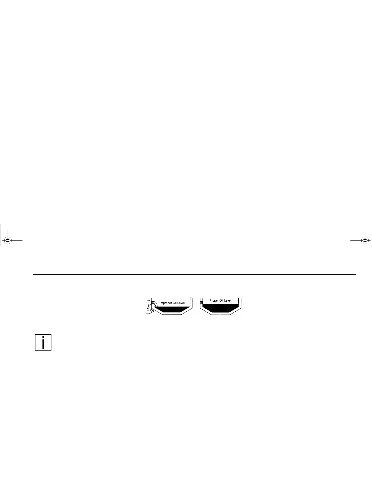
General Periodical maintenance
– 85 –
Oil Reservoirs
For oil reservoirs with side filler plugs
(transmissions, rear axl es, transfer
cases, etc.), the oil must be level with
the filler opening.
NOTE: Use care when checking the o il level with a fing er.
Just because you can reach
the oil le v el with a finger, does not mean
the oil level is correct.
Lubrication Chart
The following l ubrication sp ecificat ion s
(see Table 4 on page 86) are for an
ambient operating tempera ture r ange of
–15 to 10 0°F (–26 to 38°C) . For
extreme temperature operations, consult the comp onent manufact urer's
manuals.
PB1340A .book Page 85 Friday, Sept ember 1, 2000 7:40 AM
Page 94

General Periodical maintenance
– 86 –
Table 4 Recommended Lubrication Types
COMPONENTS RECOMMENDED LUBRICANT
Power Steering Gear Chevron Torque Fluid C4, Dexron III, or Mercon
Driveline U-Joints
Slip-Joint Splines
Cab Pivots
Clutch Pedal Shaft
Other chassis grease fittings not covered
below.
EP chassis grease, lithium 12-hydroxystearate or lithium complex base, NLGI 2.
Wheel Bearing-Non Driving Axles OIL LUBRICATED: SAE 75W-90 synthetic oil
Threaded Pins & Bushings (e.g., spring pins &
bushings)
EP grease, lithium 12-hydroxystearate or lithium complex base, NLGI 2, with 3% molybdenum
additive: Mobil Grease Special (Mobil), Molygrease EP (Chevron), or equal.
Suspension Fittings (other than threaded pins
& bushings)
EP chassis grease, lithium 12-hydroxystearate or lithium complex base, NLGI 2.
Steering Axle: Grease Fittings on Steering
Arm; Tie Rod Ends; Drag Link; King Pins
EP chassis grease, lithium 12-hydroxystearate base, NLGI 2.
Clutch Release Bearing (remove inspection
plate for access); Driveshaft Center Bearing
High temperature ball bearing grease. Chevron SRI Mobil Grease HP, Texaco Multifax 2, or
equivalent.
Automatic Slack Adjusters; Wedge Brake
Components; Disc Brake Caliper
High temperature EP grease; Texaco Thermotex EP-1, Shell Darina EP-1, Mobilith AW-1,
Rockwell 0-616A, or equivalent.
Cam Brake Camshaft Splines; Disc Brake
Shaft Splines and Slide Pin Retainers; Brake
Clevis Pins
Antiseize type grease, Rockwell specification 0-637.
Deviations from the above list of lubricants should be based on specifications published in the component manufacturer’s manuals or otherwise
approved by the manufacturer.
PB1340A .book Page 86 Friday, Sept ember 1, 2000 7:40 AM
Page 95

General Periodical maintenance
– 87 –
Brake Camshaft Bushings EP Chassis grease, lithium 12-hydroxystearate base, NLGI 2.
CAUTION: Do not contaminate brake linings with grease.
Steering Shaft Grease Fittings EP chassis grease, lithium 12-hydroxystearate base, NLGI 2.
Brake Treadle Hinge and Roller Engine oil
Lock Cylinders Lock lubricant.
Door Hinges Not required — Teflon bushings
Door Latches & Striker Plates. Polyethylene grease stick.
Door Weatherstrip Silicone lubricant.
Other Items Use manufacturer’s manuals.
Table 4 Recommended Lubrication Types
COMPONENTS RECOMMENDED LUBRICANT
Deviations from the above list of lubricants should be based on specifications published in the component manufacturer's manuals or otherwise
approved by the manufacturer.
PB1340A .book Page 87 Friday, Sept ember 1, 2000 7:40 AM
Page 96

General Periodical maintenance
– 88 –
Maintenance in Special and
Exceptional Operating
Conditions
When the vehicle is operated under
exceptional conditions, it is important to
consult your local dealer as it may be
necessar y to change the servic e intervals to suit the ope rating cond itions.
The service intervals can be adapted,
as necessary, in consultation with the
local dealer to suit the appropriate
operating conditions.
First Service
The first service inspection should be
carried out at 7500 miles (12,000 km)
and no later than twelve weeks after the
vehicle delivery date, whichever comes
first.
Cab Ma intenance
In order to maintain the quality of the
surface and paint finish during vehicle
operation, regular maintenance must
be carried out on t he exposed areas of
the cab.
To prevent the formation of rust in b oxsection areas and other hollow areas,
the cab is double galvanized and waxed
during production.
Preventive Maintenance
Before the Winter Season
Checking the Anti-freeze Content
WARNING! Before attempting t o ch eck t h e an ti- fr eez e
ensure that the following
safety instructions are
observed:
– Do not attempt to remove
the surge tank filler cap
while the engine is running
or still hot.
– Do not fill/top off the cooling
system through the pressure
cap aperture.
– Do not attempt t o fill/top off
a hot engine with cold coolant.
– Anti-freeze solutions con-
tain toxic chemicals which
must not be consumed or
allowed to come into skin
contact. Use impervious protective clothing and gloves
when handli ng antifr eez e . In
the event of sl ight ski n contact, thoroughly rinse the
affected area with water. If
there i s exces si ve s kin co n tact, ingestion or inhalation
seek medical advice immediately.
PB1340A .book Page 88 Friday, Sept ember 1, 2000 7:40 AM
Page 97

General Periodical maintenance
– 89 –
NOTE: All new vehicles are
factory filled with a 50% anti-
freeze so lut ion w hich w ill g ive
frost pr otection dow n to - 34
°
F
(-36
°
C).
CAUTION: The use of anti-
freeze that does not conform
to the req uired s pecif ication
can cause severe damage to
the cooling system and its
components.
The anti-free ze m ixt ure must rema in
in the cooling system during the
summer months.
I
1. Remove the filler cap from the
surge tank.
2. Using 2-way test strips, perform
freeze point and nitrite level tests
per coolant supplier’s recommendations. Supply additives and coolant/water mixture as indicated.
CAUTION: Damage to the
engine and cooling system,
such a s co r rosio n a nd cav itation erosion, will occur
unless an tifreeze ZEREX
PENRAY 2792 is used and
maintaine d wi th s upp lemen tal coolant additive Pencool
3000 with Stabil-Aid. As
needed, fill or top off the
cooling s ystem o nly with a
ready-mixed clean water/
approved antifreeze solution
using these product s. The
use of other antifreeze products will void your engine,
radiator, and cooling system
warranties.
3. The cooling system should be filled
with rea dy-mixed clea n water /anti freeze solut ion whic h conforms
with the required specifications.
PB1340A .book Page 89 Friday, Sept ember 1, 2000 7:40 AM
Page 98

Periodical maintenance
– 90 –
NOTES
PB1340A .book Page 90 Friday, Sept ember 1, 2000 7:40 AM
Page 99

Emergency repairs
– 91 –
EMERGEN CY REPAIRS
Vehicl e Tool Ki t
All vehicles are equipped wi th an e xtension ha ndle for tiltin g the cab. It is
secured within the passenger’s
seat
stowage compartment (twin seat) or,
alternatively, secured behind the passenger’s seat (single seat).
Replacing The Drive Belt
IMPORTANT: Always inst all
the correct replacement drive
belt.
Refer to the engine manufacturer’s
Operation and Maintenance Manual.
Drive belt tension
All engines a re equ ippe d with an au tomatic drive belt t ensioner and, the refore, cannot be manually adjusted. In
the event of incorrect drive belt tension,
consult your dealer at the earliest
opportunity.
Replacing The Compressor
Belt
(A/C and Compressor is optional)
IMPORTANT: Always install
the correct replacement drive
belt.
1. Disconnect the batteries, nega-
tive termi nal first, the n positive
terminal
.
2. Fully tilt the cab.
3. Loosen the adjusting screw
retainer bolt (1) , but do not
remove.
4. Loosen the jam nut (3).
5. Loosen the tensioning bolt (4).
6. Pivot the compressor to slacken
the belt.
7. Remove the compressor belt (5).
1
2
3
4
5
PB1340A .book Page 91 Friday, Sept ember 1, 2000 7:40 AM
Page 100

Emergency repairs
– 92 –
8. Clean the pulleys and ensure that
they are free of any contaminants
(oil/fuel/dirt).
9. Install a new belt.
10. Pivot the compressor to tighten the
belt and hold the tension by setting
the adjustment screw. Torque the
mount ing screw s to 17 to 23 lb. ft.
(23 to 31 Nm).
11. Lower the cab and re-connect the
batteries, positive terminal first.
Replacing The Fuel Filter
WARNING! Diesel fuel is
flammable and must not be
exposed to an open flame or
other sources of h eat such
as a hot engine. Collect the
escaping fuel in a suitable
container.
For deta iled infor mati on, refer to the
Engine Operation and Maintenance
Manual
provided.
NOTE: Small amounts of air
introduced into the fuel system
when refitting the filter cartridge will be vented automat ically providing the filter
cartridge has been filled with
diesel fuel prior to installation.
Adjusting The Brakes
Adjustment of the brake shoes is fully
automatic.
Spring Brakes — Manual
Release
In order to tow a vehicle, if there is
insufficient air to release the p arkin g
brake, the spring bra kes can b e ma nually released.
WARNING! Never drive you r
vehicle with the parking
brake applied. Always
release the parking brakes
prior to moving the vehicle.
Failure to di sengage the
parking brakes prior to moving your vehicle could result
in excessive heat build-up in
the brake system, resulting
in a fire.
NOTE: Today’s diesel electronic engines have significant
torque and startability power at
low RPM. Combinations of
engine spee d and available
torque may over-power the
vehicle’s parking brakes.
NOTE: Suitable wheel chocks
are at a minimum an 18-inch
(46 cm) long 4x4.
PB1340A .book Page 92 Friday, Sept ember 1, 2000 7:40 AM
 Loading...