

Page 1

Perkins 2300 Series
This document has been printed from SPI². Not for Resale
Model 2306C-E14
WORKSHOP MANUAL
6 cylinder turbocharged diesel engines for industrial applications
Publication TSD3455E, Issue 1
© Proprietary information of Perkins Engines Company Limited, all rights reserved.
The information is correct at the time of print.
Published in September 2002 by Technical Publications,
Perkins Engines Company Limited, Shrewsbury SY1 3NX, England
i
Page 2

This document has been printed from SPI². Not for Resale
Chapters
1 General information
2 Specifications
3 Cylinder head assembly
4 Piston and connecting rod assemblies
5 Crankshaft assembly
6 Gear case and drive assembly
7 Crankcase and cylinder liners
8 Engine timing and electronic controls
9 Aspiration system
10 Lubrication system
11 Fuel system
12 Cooling system
13 Flywheel and housing
14 Electrical equipment
15 Auxiliary equipment
16 Special tools
The pages which follow contain a detailed table of contents
ii
Page 3

2300
This document has been printed from SPI². Not for Resale
Contents
1 General information
Introduction ... ... ... ... ... ... ... ... ... ... ... ... ... ... ... ... ... ... ... ... ... ... ... ... ... ... ... ... ... ...1
Safety precautions ... ... ... ... ... ... ... ... ... ... ... ... ... ... ... ... ... ... ... ... ... ... ... ... ... ... ...2
Viton seals . ... ... ... ... ... ... ... ... ... ... ... ... ... ... ... ... ... ... ... ... ... ... ... ... ... ... ... ... ... ...4
Welding .. ... ... ... ... ... ... ... ... ... ... ... ... ... ... ... ... ... ... ... ... ... ... ... ... ... ... ... ... ... ... ...4
Environmental protection ... ... ... ... ... ... ... ... ... ... ... ... ... ... ... ... ... ... ... ... ... ... ... ...4
Engine views . ... ... ... ... ... ... ... ... ... ... ... ... ... ... ... ... ... ... ... ... ... ... ... ... ... ... ... ... ...5
Engine identification . ... ... ... ... ... ... ... ... ... ... ... ... ... ... ... ... ... ... ... ... ... ... ... ... ... ...6
Engine lift equipment ... ... ... ... ... ... ... ... ... ... ... ... ... ... ... ... ... ... ... ... ... ... ... ... ... ...6
2 Specifications
Basic engine data - 2306 engine .. ... ... ... ... ... ... ... ... ... ... ... ... ... ... ... ... ... ... ... ... ...7
Basic engine data - 2806 engine .. ... ... ... ... ... ... ... ... ... ... ... ... ... ... ... ... ... ... ... ... ...7
Rocker assemblies ... ... ... ... ... ... ... ... ... ... ... ... ... ... ... ... ... ... ... ... ... ... ... ... ... ... ...8
Valves . ... ... ... ... ... ... ... ... ... ... ... ... ... ... ... ... ... ... ... ... ... ... ... ... ... ... ... ... ... ... ... ...9
Valve guides .. ... ... ... ... ... ... ... ... ... ... ... ... ... ... ... ... ... ... ... ... ... ... ... ... ... ... ... ... .10
Valve springs . ... ... ... ... ... ... ... ... ... ... ... ... ... ... ... ... ... ... ... ... ... ... ... ... ... ... ... ... .10
Valve seat inserts .. ... ... ... ... ... ... ... ... ... ... ... ... ... ... ... ... ... ... ... ... ... ... ... ... ... ... .11
Workshop Manual, TSD3455E, Issue 1 iii
Page 4

2300
This document has been printed from SPI². Not for Resale
Cylinder head . ... ... ... ... ... ... ... ... ... ... ... ... ... ... ... ... ... ... ... ... ... ... ... ... ... ... ... ... 12
Camshaft and bearings . ... ... ... ... ... ... ... ... ... ... ... ... ... ... ... ... ... ... ... ... ... ... ... ... 12
Pistons and connecting rods - 2306 engine ... ... ... ... ... ... ... ... ... ... ... ... ... ... ... ... 13
Pistons and connecting rods - 2806 engine ... ... ... ... ... ... ... ... ... ... ... ... ... ... ... ... 14
Crankshaft, main bearings and flywheel . ... ... ... ... ... ... ... ... ... ... ... ... ... ... ... ... ... 15
Crankshaft damper ... ... ... ... ... ... ... ... ... ... ... ... ... ... ... ... ... ... ... ... ... ... ... ... ... ... 15
Crankcase and cylinder liners .. ... ... ... ... ... ... ... ... ... ... ... ... ... ... ... ... ... ... ... ... ... 16
Lubricating oil pump . ... ... ... ... ... ... ... ... ... ... ... ... ... ... ... ... ... ... ... ... ... ... ... ... ... 18
Coolant pump ... ... ... ... ... ... ... ... ... ... ... ... ... ... ... ... ... ... ... ... ... ... ... ... ... ... ... ... 19
Recommended torque figures .. ... ... ... ... ... ... ... ... ... ... ... ... ... ... ... ... ... ... ... ... ... 20
3 Cylinder head assembly
General information .. ... ... ... ... ... ... ... ... ... ... ... ... ... ... ... ... ... ... ... ... ... ... ... ... ... 27
Rocker cover
Operation 3-1 To remove and to fit ... ... ... ... ... ... ... ... ... ... ... ... ... ... ... ... ... ... ... ... 28
Rocker leve r and rocker shaft assemblies
Operation 3-2 To remove and to fit ... ... ... ... ... ... ... ... ... ... ... ... ... ... ... ... ... ... ... ... 29
Operation 3-3 To dismantle and to assemble ... ... ... ... ... ... ... ... ... ... ... ... ... ... ... ... 30
Operation 3-4 How to check/adjust the tappet clearances ... ... ... ... ... ... ... ... ... ... ... 32
Cylinder head assembly
Operation 3-5 To remove and to fit ... ... ... ... ... ... ... ... ... ... ... ... ... ... ... ... ... ... ... ... 35
Valve springs
Operation 3-6 To remove and to fit ... ... ... ... ... ... ... ... ... ... ... ... ... ... ... ... ... ... ... ... 39
Valves
Operation 3-7 To remove and to fit ... ... ... ... ... ... ... ... ... ... ... ... ... ... ... ... ... ... ... ... 41
Valve seals
Operation 3-8 To renew . ... ... ... ... ... ... ... ... ... ... ... ... ... ... ... ... ... ... ... ... ... ... ... ... 42
Valve guides
Operation 3-9 To remove and to fit ... ... ... ... ... ... ... ... ... ... ... ... ... ... ... ... ... ... ... ... 43
Camshaft
iv Workshop Manual, TSD3455E, Issue 1
Page 5

2300
This document has been printed from SPI². Not for Resale
Operation 3-10 To remove and to fit . ... ... ... ... ... ... ... ... ... ... ... ... ... ... ... ... ... ... ... .45
Operation 3-11 How to set the backlash for the camshaft gear ... ... ... ... ... ... ... ... ... .50
Electronic injector units
Operation 3-12 To remove and to fit . ... ... ... ... ... ... ... ... ... ... ... ... ... ... ... ... ... ... ... .51
Operation 3-13 To check and to adjust . ... ... ... ... ... ... ... ... ... ... ... ... ... ... ... ... ... ... .53
Injector sleeves
Operation 3-14 To remove and to fit . ... ... ... ... ... ... ... ... ... ... ... ... ... ... ... ... ... ... ... .54
4 Pistons and connecting rod assemblies
General information .. ... ... ... ... ... ... ... ... ... ... ... ... ... ... ... ... ... ... ... ... ... ... ... ... ... .57
Pistons and connecting rod assemblies
Operation 4-1 To remove and to fit ... ... ... ... ... ... ... ... ... ... ... ... ... ... ... ... ... ... ... ... .58
Operation 4-2 To dismantle and assemble ... ... ... ... ... ... ... ... ... ... ... ... ... ... ... ... ... .60
Piston cooling jets
Operation 4-3 To remove and to fit ... ... ... ... ... ... ... ... ... ... ... ... ... ... ... ... ... ... ... ... .62
5 Crankshaft assembly
General information .. ... ... ... ... ... ... ... ... ... ... ... ... ... ... ... ... ... ... ... ... ... ... ... ... ... .63
Crankshaft
Operation 5-1 To remove and to fit ... ... ... ... ... ... ... ... ... ... ... ... ... ... ... ... ... ... ... ... .64
Crankshaft front seal and wear sleeve
Operation 5-2 To renew ... ... ... ... ... ... ... ... ... ... ... ... ... ... ... ... ... ... ... ... ... ... ... ... .66
Crankshaft rear seal and wear sleeve
Operation 5-3 To renew ... ... ... ... ... ... ... ... ... ... ... ... ... ... ... ... ... ... ... ... ... ... ... ... .68
Crankshaft vibration d amp er
Operation 5-4 To remove and to fit ... ... ... ... ... ... ... ... ... ... ... ... ... ... ... ... ... ... ... ... .70
6 Gear case and drive assembly
General information .. ... ... ... ... ... ... ... ... ... ... ... ... ... ... ... ... ... ... ... ... ... ... ... ... ... .73
Gear case cover
Operation 6-1 To remove and to fit ... ... ... ... ... ... ... ... ... ... ... ... ... ... ... ... ... ... ... ... .74
Workshop Manual, TSD3455E, Issue 1 v
Page 6

2300
This document has been printed from SPI². Not for Resale
Timing gears
Operation 6-2 To remove and to fit ... ... ... ... ... ... ... ... ... ... ... ... ... ... ... ... ... ... ... ... 75
Operation 6-3 How to check the position of the timing gears ... ... ... ... ... ... ... ... ... ... 78
Gear case
Operation 6-4 To remove and to fit ... ... ... ... ... ... ... ... ... ... ... ... ... ... ... ... ... ... ... ... 79
7 Crankcase and cylinder liners
General information .. ... ... ... ... ... ... ... ... ... ... ... ... ... ... ... ... ... ... ... ... ... ... ... ... ... 81
Front engine support
Operation 7-1 To remove and to fit ... ... ... ... ... ... ... ... ... ... ... ... ... ... ... ... ... ... ... ... 82
Cylinder liners
Operation 7-2 To remove and to fit ... ... ... ... ... ... ... ... ... ... ... ... ... ... ... ... ... ... ... ... 83
Operation 7-3 To check and to adjust the protrusion of the cylinder liners ... ... ... ... ... 84
8 Engine timing and electronic controls
General information .. ... ... ... ... ... ... ... ... ... ... ... ... ... ... ... ... ... ... ... ... ... ... ... ... ... 87
Electronic control module
Operation 8-1 To remove and to fit ... ... ... ... ... ... ... ... ... ... ... ... ... ... ... ... ... ... ... ... 88
Engine timing
Operation 8-2 To check . ... ... ... ... ... ... ... ... ... ... ... ... ... ... ... ... ... ... ... ... ... ... ... ... 89
9 Aspiration system
General information .. ... ... ... ... ... ... ... ... ... ... ... ... ... ... ... ... ... ... ... ... ... ... ... ... ... 91
Exhaust manifold
Operation 9-1 To remove and to fit ... ... ... ... ... ... ... ... ... ... ... ... ... ... ... ... ... ... ... ... 92
Turbocharger
Operation 9-2 To remove and to fit ... ... ... ... ... ... ... ... ... ... ... ... ... ... ... ... ... ... ... ... 93
Operation 9-3 To dismantle and to assemble ... ... ... ... ... ... ... ... ... ... ... ... ... ... ... ... 94
vi Workshop Manual, TSD3455E, Issue 1
Page 7

2300
This document has been printed from SPI². Not for Resale
10 Lubrication system
General information .. ... ... ... ... ... ... ... ... ... ... ... ... ... ... ... ... ... ... ... ... ... ... ... ... ... .95
Oil filter and oil filter header
Operation 10-1 To remove and to fit . ... ... ... ... ... ... ... ... ... ... ... ... ... ... ... ... ... ... ... .96
Oil filter header
Operation 10-2 To dismantle and to assemble . ... ... ... ... ... ... ... ... ... ... ... ... ... ... ... .98
Sump
Operation 10-3 To remove and to fit . ... ... ... ... ... ... ... ... ... ... ... ... ... ... ... ... ... ... ... .99
Oil pump
Operation 10-4 To remove and to fit . ... ... ... ... ... ... ... ... ... ... ... ... ... ... ... ... ... ... ...101
Operation 10-5 To dismantle and to assemble . ... ... ... ... ... ... ... ... ... ... ... ... ... ... ...102
11 Fuel system
General information .. ... ... ... ... ... ... ... ... ... ... ... ... ... ... ... ... ... ... ... ... ... ... ... ... ...103
Fuel priming pump
Operation 11-1 To remove and to fit . ... ... ... ... ... ... ... ... ... ... ... ... ... ... ... ... ... ... ...104
Fuel transfer pump
Operation 11-2 To remove and to fit . ... ... ... ... ... ... ... ... ... ... ... ... ... ... ... ... ... ... ...105
Operation 11-3 To test .. ... ... ... ... ... ... ... ... ... ... ... ... ... ... ... ... ... ... ... ... ... ... ... ...106
Drive for the fuel transfe r pump
Operation 11-4 To remove and to fit . ... ... ... ... ... ... ... ... ... ... ... ... ... ... ... ... ... ... ...107
Fuel filter header
Operation 11-5 To remove and to fit . ... ... ... ... ... ... ... ... ... ... ... ... ... ... ... ... ... ... ...108
Low pressure fuel system
Operation 11-6 How to eliminate air from the fuel system ... ... ... ... ... ... ... ... ... ... ...109
12 Cooling system
General information .. ... ... ... ... ... ... ... ... ... ... ... ... ... ... ... ... ... ... ... ... ... ... ... ... ...111
Cooling system
Operation 12-1 To inspect . ... ... ... ... ... ... ... ... ... ... ... ... ... ... ... ... ... ... ... ... ... ... ...112
Operation 12-2 Leakage test . ... ... ... ... ... ... ... ... ... ... ... ... ... ... ... ... ... ... ... ... ... ...113
Workshop Manual, TSD3455E, Issue 1 vii
Page 8

2300
This document has been printed from SPI². Not for Resale
Coolant filler cap
Operation 12-3 To test ... ... ... ... ... ... ... ... ... ... ... ... ... ... ... ... ... ... ... ... ... ... ... ... .. 114
Radiator
Operation 12-4 To remove and to fit .. ... ... ... ... ... ... ... ... ... ... ... ... ... ... ... ... ... ... .. 115
Fan
Operation 12-5 To remove and to fit .. ... ... ... ... ... ... ... ... ... ... ... ... ... ... ... ... ... ... .. 116
Fan drive assembly
Operation 12-6 To remove and to fit .. ... ... ... ... ... ... ... ... ... ... ... ... ... ... ... ... ... ... .. 117
Fan drive belts
Operation 12-7 To check and to adjust the tension ... ... ... ... ... ... ... ... ... ... ... ... ... .. 118
Operation 12-8 To renew ... ... ... ... ... ... ... ... ... ... ... ... ... ... ... ... ... ... ... ... ... ... ... .. 119
Engine oil cooler
Operation 12-9 To remove and to fit .. ... ... ... ... ... ... ... ... ... ... ... ... ... ... ... ... ... ... .. 120
Thermostats and thermostat housing
Operation 12-10 To remove and to fit ... ... ... ... ... ... ... ... ... ... ... ... ... ... ... ... ... ... .. 121
Operation 12-11 To test the thermostats ... ... ... ... ... ... ... ... ... ... ... ... ... ... ... ... ... .. 123
Coolant temperature sensor
Operation 12-12 To test . ... ... ... ... ... ... ... ... ... ... ... ... ... ... ... ... ... ... ... ... ... ... ... .. 124
Coolant pump
Operation 12-13 To remove and to fit ... ... ... ... ... ... ... ... ... ... ... ... ... ... ... ... ... ... .. 125
Operation 12-14 To dismantle and to assemble ... ... ... ... ... ... ... ... ... ... ... ... ... ... .. 126
Operation 12-15 To test the pressure of the coolant pump ... ... ... ... ... ... ... ... ... ... .. 128
13 Flywheel and housing
General information .. ... ... ... ... ... ... ... ... ... ... ... ... ... ... ... ... ... ... ... ... ... ... ... ... .. 129
Flywheel
Operation 13-1 To remove and to fit .. ... ... ... ... ... ... ... ... ... ... ... ... ... ... ... ... ... ... .. 130
Flywheel housing
Operation 13-2 To remove and to fit .. ... ... ... ... ... ... ... ... ... ... ... ... ... ... ... ... ... ... .. 131
viii Workshop Manual, TSD3455E, Issue 1
Page 9

2300
This document has been printed from SPI². Not for Resale
14 Electrical equipment
General information .. ... ... ... ... ... ... ... ... ... ... ... ... ... ... ... ... ... ... ... ... ... ... ... ... ...133
Starter motor
Operation 14-1 To remove and to fit . ... ... ... ... ... ... ... ... ... ... ... ... ... ... ... ... ... ... ...134
Alternator
Operation 14-2 To remove and to fit . ... ... ... ... ... ... ... ... ... ... ... ... ... ... ... ... ... ... ...135
Operation 14-3 To check and to adjust the tension of the alternator belt .. ... ... ... ... ...136
Operation 14-4 To renew the alternator belt . ... ... ... ... ... ... ... ... ... ... ... ... ... ... ... ...137
15 Auxiliary equipment
General information .. ... ... ... ... ... ... ... ... ... ... ... ... ... ... ... ... ... ... ... ... ... ... ... ... ...139
Oil sample valve ... ... ... ... ... ... ... ... ... ... ... ... ... ... ... ... ... ... ... ... ... ... ... ... ... ... ...139
16 Special tools
List of special tools .. ... ... ... ... ... ... ... ... ... ... ... ... ... ... ... ... ... ... ... ... ... ... ... ... ...141
Workshop Manual, TSD3455E, Issue 1 ix
Page 10

2300
This document has been printed from SPI². Not for Resale
x Workshop Manual, TSD3455E, Issue 1
Page 11

2300
This document has been printed from SPI². Not for Resale
1
General information 1
Introduction
The 2300 and 2800 Series engines are from Perkins Engines Company Limited, a world leader in the design
and manufacture of high-performance diesel engines.
Perkins approved assembly and quality standards, together with the latest technology, have been applied to
the manufacture of your engine to give you reliable and economic power.
This Workshop Manual has been designed to provide assistance in the service and the overhaul of Perkins
2300 and 2800 Series engines. Most of the general information, which is included in the User’s Handbook
(Chapters 1 to 6), has not been repeated in this Workshop Manual and the two publications should be used
together.
To ensure that you use the relevant information for your specific engine type, refer to "Engine identification"
on page 6.
When reference is made to the "left" or "right" side of the engine, this is as seen from the flywheel end of the
engine.
Special tools have been made available and a list of these is given in Chapter 16, Special tools. Reference to
the relevant special tools is also made at the beginning of each operation.
Data and dimensions are included in Chapter 2, Specifications.
Read the "Safety precautions" on page 2 and remember them. They are given for your protection and must be
applied at all times.
In addition to the general safety precautions, danger to both operator and engine are highlighted by the
following conventions:
Warning! This indicates that there is a possible danger to the person (or the person and engine).
Caution: This indicates that there is a possible danger to the engine.
Note: Is used where the information is important, but there is not a danger.
Workshop Manual, TSD3455E, Issue 1 1
Page 12

1
This document has been printed from SPI². Not for Resale
2300
Safety precautions
These safety precautions are important. You must refer also to the local regulations in the country of use.
Some items only apply to specific applications.
l Always refer to the text of this handbook for specific warnings and cautions.
l Only use these engines in the type of application for which they have been designed.
l Do not change the specification of the engine.
l Do not make adjustments that you do not understand.
l Do not allow the engine to stand on its sump.
l Do not smoke when you put fuel in the tank.
l Clean away fuel which has been spilt. Material which has been contaminated by fuel must be moved to a
safe place.
l Do not put fuel in the tank while the engine runs (unless it is absolutely necessary).
l Do not clean, add lubricating oil, or adjust the engine while it runs (unless you have had the correct training;
even then extreme caution must be used to prevent injury).
l Ensure that the engine does not run in a location where it can cause a concentration of toxic emissions.
l Other persons must be kept at a safe distance while the engine or auxiliary equipment is in operation.
l Do not permit loose clothing or long hair near moving parts.
Warning! Keep away from moving parts during engine operation. Some moving parts cannot be seen clearly
while the engine runs.
l Do not operate the engine if a safety guard has been removed.
l Do not remove the filler cap or any component of the coolant system while the engine is hot and while the
coolant is under pressure, because dangerous hot coolant can be discharged.
l Do not allow sparks or fire near the batteries (especially when the batteries are on charge) because the
gases from the electrolyte are highly flammable. The battery fluid is dangerous to the skin and especially
to the eyes.
l Disconnect the battery terminals before a repair is made to the electrical system. Always disconnect the
negative terminal first.
l Only one person must control the engine.
l Ensure that the engine is operated only from the control panel or from the operator’s position.
l If your skin comes into contact with high-pressure fuel, obtain medical assistance immediately.
l Diesel fuel and lubricating oil (especially used lubricating oil) can damage the skin of certain persons.
Protect your hands with gloves or a special solution to protect the skin.
l Do not wear clothing which is contaminated by lubricating oil. Do not put material which is contaminated
with oil into the pockets.
l Discard used lubricating oil and coolant in accordance with local regulations to prevent contamination.
l The combustible material of some components of the engine (for example certain seals) can become
extremely dangerous if it is burned. Never allow this burnt material to come into contact with the skin or with
the eyes.
Continued
2 Workshop Manual, TSD3455E, Issue 1
Page 13

2300
This document has been printed from SPI². Not for Resale
l Always use a safety cage to protect the operator when a component is to be pressure tested in a container
of water. Fit safety wires to secure the plugs which seal the hose connections of a component which is to
be pressure tested.
l Do not allow compressed air to contact your skin. If compressed air enters your skin, obtain medical help
immediately.
l Turbochargers operate at high speed and at high temperatures. Keep fingers, tools and debris away from
the inlet and outlet ports of the turbocharger and prevent contact with hot surfaces.
l Some components are not waterproof and should not be washed with a high-pressure water jet or steam.
l Fit only genuine Perkins parts.
1
Workshop Manual, TSD3455E, Issue 1 3
Page 14

1
C
This document has been printed from SPI². Not for Resale
2300
Viton seals
Some seals used in engines and in components fitted to engines are made from Viton (fluorocarbon).
Viton is used by many manufacturers and is a safe material under normal conditions of operation.
If Viton is burned, a product of this burnt material is an acid which is extremely dangerous. Never allow this
burnt material to come into contact with the skin or with the eyes.
If it is necessary to come into contact with components which have been burnt, ensure that the precautions
which follow are used:
l Ensure that the components have cooled.
l Use Neoprene gloves and discard the gloves safely after use.
l Wash the area with a calcium hydroxide solution and then with clean water.
l Disposal of gloves and components which are contaminated, must be in accordance with local regulations.
If there is contamination of the skin or eyes, wash the affected area with a continuous supply of clean water or
with a calcium hydroxide solution for 15-60 minutes. Obtain immediate medical attention.
Welding
Welding can cause damage to the electronic components fitted to the engine. If welding is necessary, the
precautions which follow must be undertaken before and during the welding operation.
autions:
l Switch off the engine.
l Disconnect the cable from the negative terminal of the battery. If the machine is fitted with a battery
disconnect the switch then open the switch.
l If welding to the engine, remove the ECM (electronic control module).
l If welding onto the machine chassis, ensure that the earth clamp is attached as close to the welding point
as possible and NOT near to the ECM.
l If it is necessary to weld near to the ECM, remove the ECM from the engine.
Environmental protection
There is legislation to protect the environment from the incorrect disposal of used lubricating oil. To ensure that
the environment is protected, consult your Local Authority who can give advice.
4 Workshop Manual, TSD3455E, Issue 1
Page 15
2300
This document has been printed from SPI². Not for Resale
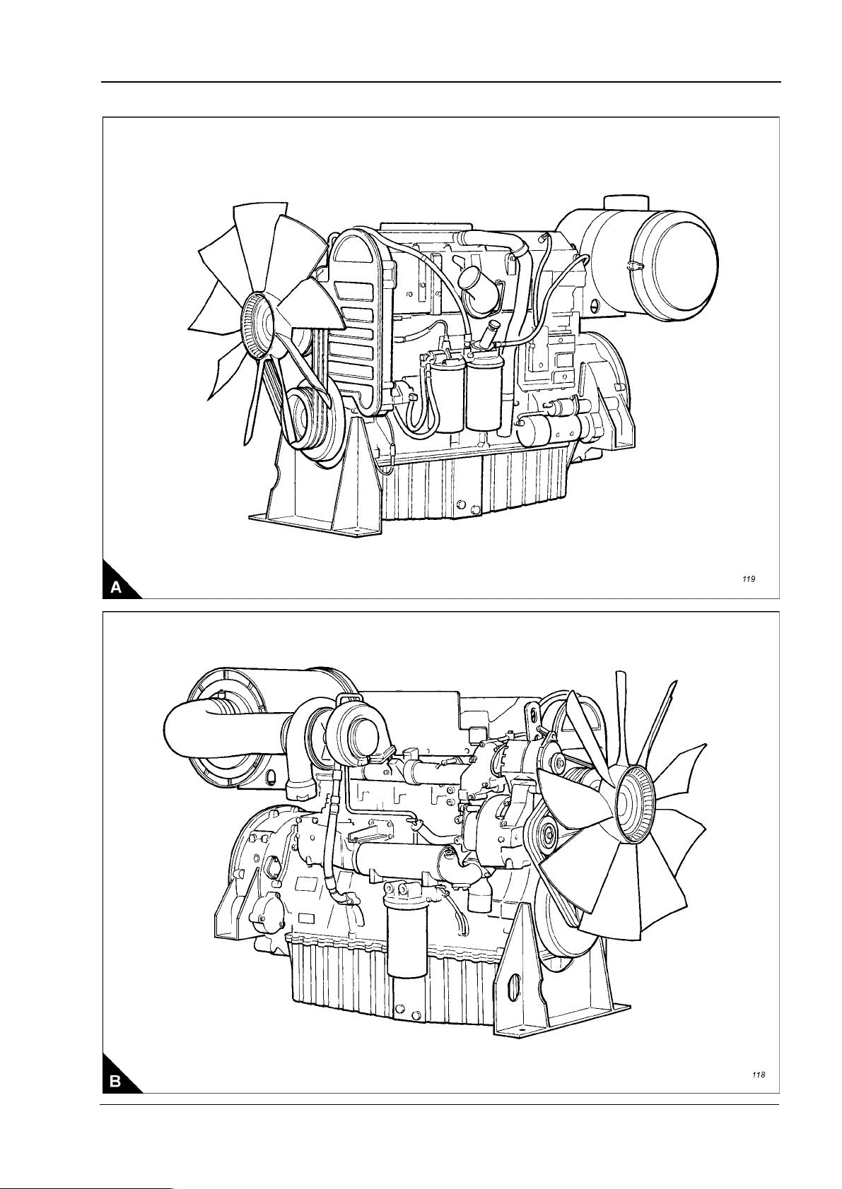
Engine views
1
Workshop Manual, TSD3455E, Issue 1 5
Page 16

1
This document has been printed from SPI². Not for Resale
2300
Engine identification
If you need parts, service or information for your engine, you must give the complete engine number. The
engine number is stamped on a data plate which is fastened to the right side of the engine.
A typical engine number is: HGA060125U 1103H, which consists of these codes:
H Code for engine capacity
G Engine application
A Engine type
06 Number of engine cylinders
0125 Engine specification number
U The country of manufacture
1103 Build line number
H Year of manufacture
Engine lift equipment
A dry engine weighs approximately 1551 kg (3,419 lb). Ensure that the lift equipment used is suitable. An
adjustable lifting beam should be used and the chains or cables must be parallel to each other during use.
Before the engine is lifted:
l Always use lift equipment of the approved type and of the correct capacity to lift the engine. Never use a
single lift bracket to raise an engine.
l Check the engine lift brackets for damage and security before the engine is lifted.
Use suitable lift equipment or obtain assistance to lift heavy engine components such as the cylinder block,
cylinder head, damper unit, flywheel housing, crankshaft and flywheel.
Warning! The lifting eyes which are fitted to the engine must be used for lifting only the engine. Do NOT use
them to lift the engine if it is still attached to its driven unit.
6 Workshop Manual, TSD3455E, Issue 1
Page 17

2300
This document has been printed from SPI². Not for Resale
2
Specifications 2
Basic engine data - 2306 engine
Number of cylinders. ... ... ... ... ... ... ... ... ... ... ... ... ... ... ... ... ... ... ... ... ... ... ... ... ... ... ... ... ... ... ... ... ... ... 6
Cylinder arrangement.. ... ... ... ... ... ... ... ... ... ... ... ... ... ... ... ... ... ... ... ... ... ... ... ... ... ... ... ... ... ... ... .In line
Cycle ... ... ... ... ... ... ... ... ... ... ... ... ... ... ... ... ... ... ... ... ... ... ... ... ... ... ... ... ... ... ... ... ... ... ... ... Four stroke
Induction system.. ... ... ... ... ... ... ... ... ... ... ... ... ... ... ... ... ... ... ... ... ... ... ... ... ... ... ... ... ... ... Turbocharged
Combustion system. ... ... ... ... ... ... ... ... ... ... ... ... ... ... ... ... ... ... ... ... ... ... ... ... ... ... ... ... ...Direct injection
Nominal bore ... ... ... ... ... ... ... ... ... ... ... ... ... ... ... ... ... ... ... ... ... ... ... ... ... ... ... ... ... ... .137 mm (5.394 in)
Nominal stroke. ... ... ... ... ... ... ... ... ... ... ... ... ... ... ... ... ... ... ... ... ... ... ... ... ... ... ... ... ... .165 mm (6.496 in)
Compression ratio ... ... ... ... ... ... ... ... ... ... ... ... ... ... ... ... ... ... ... ... ... ... ... ... ... ... ... ... ... ... ... ... ... 15.9:1
Cubic capacity . ... ... ... ... ... ... ... ... ... ... ... ... ... ... ... ... ... ... ... ... ... ... ... ... ... ... ... ... ... 14,6 litres (893 in
Firing order .. ... ... ... ... ... ... ... ... ... ... ... ... ... ... ... ... ... ... ... ... ... ... ... ... ... ... ... ... ... ... ... ... 1, 5, 3, 6, 2, 4
Direction of rotation . ... ... ... ... ... ... ... ... ... ... ... ... ... ... ... ... ... ... ... ... ... Anti-clockwise viewed on flywheel
Lubricating oil capacity:
Total system ... ... ... ... ... ... ... ... ... ... ... ... ... ... ... ... ... ... ... ... ... ... ... ... ... ... ... ... ..68 litres (1 20 UK pints)
Sump maximum... ... ... ... ... ... ... ... ... ... ... ... ... ... ... ... ... ... ... ... ... ... ... ... ... ... ... ..60 litres (106 UK pints)
Sump minimum ... ... ... ... ... ... ... ... ... ... ... ... ... ... ... ... ... ... ... ... ... ... ... ... ... ... ... ... 45 litres (79 UK pints)
Lubricating oil pressure:
3
)
At rated speed . ... ... ... ... ... ... ... ... ... ... ... ... ... ... ... ... ... ... ... ... ... ... ... ... ... ... ... ... ... ... ... ... ... ...4,5 bar
Typical coolant capacity of engine... ... ... ... ... ... ... ... ... ... ... ... ... ... ... ... ... ... ... 20,8 litres (4.6 UK gallons)
Typical coolant capacity of engine and radiator .. ... ... ... ... ... ... ... ... ... ... ... ... ... .47 litres (10.3 UK gallons)
Basic engine data - 2806 engine
Number of cylinders. ... ... ... ... ... ... ... ... ... ... ... ... ... ... ... ... ... ... ... ... ... ... ... ... ... ... ... ... ... ... ... ... ... ... 6
Cylinder arrangement.. ... ... ... ... ... ... ... ... ... ... ... ... ... ... ... ... ... ... ... ... ... ... ... ... ... ... ... ... ... ... ... .In line
Cycle ... ... ... ... ... ... ... ... ... ... ... ... ... ... ... ... ... ... ... ... ... ... ... ... ... ... ... ... ... ... ... ... ... ... ... ... Four stroke
Induction system.. ... ... ... ... ... ... ... ... ... ... ... ... ... ... ... ... ... ... ... ... ... ... ... ... ... ... ... ... ... ... Turbocharged
Combustion system. ... ... ... ... ... ... ... ... ... ... ... ... ... ... ... ... ... ... ... ... ... ... ... ... ... ... ... ... ...Direct injection
Nominal bore ... ... ... ... ... ... ... ... ... ... ... ... ... ... ... ... ... ... ... ... ... ... ... ... ... ... ... ... ... ... .140 mm (5.512 in)
Nominal stroke. ... ... ... ... ... ... ... ... ... ... ... ... ... ... ... ... ... ... ... ... ... ... ... ... ... ... ... ... ... .171 mm (6.732 in)
Compression ratio ... ... ... ... ... ... ... ... ... ... ... ... ... ... ... ... ... ... ... ... ... ... ... ... ... ... ... ... ... ... ... ... ... 15.9:1
Cubic capacity . ... ... ... ... ... ... ... ... ... ... ... ... ... ... ... ... ... ... ... ... ... ... ... ... ... ... ... ...15,8 litres (964.18 in
Firing order .. ... ... ... ... ... ... ... ... ... ... ... ... ... ... ... ... ... ... ... ... ... ... ... ... ... ... ... ... ... ... ... ... 1, 5, 3, 6, 2, 4
Direction of rotation . ... ... ... ... ... ... ... ... ... ... ... ... ... ... ... ... ... ... ... ... ... Anti-clockwise viewed on flywheel
Lubricating oil capacity:
Total system ... ... ... ... ... ... ... ... ... ... ... ... ... ... ... ... ... ... ... ... ... ... ... ... ... ... ... ... ..68 litres (1 20 UK pint s)
Sump maximum... ... ... ... ... ... ... ... ... ... ... ... ... ... ... ... ... ... ... ... ... ... ... ... ... ... ... ..60 litres (106 UK pints)
Sump minimum ... ... ... ... ... ... ... ... ... ... ... ... ... ... ... ... ... ... ... ... ... ... ... ... ... ... ... ... 45 litres (79 UK pints)
Lubricating oil pressure:
3
)
At rated speed . ... ... ... ... ... ... ... ... ... ... ... ... ... ... ... ... ... ... ... ... ... ... ... ... ... ... ... ... ... ... ... ... ... ...4,5 bar
Typical coolant capacity of engine... ... ... ... ... ... ... ... ... ... ... ... ... ... ... ... ... ... ... 20,8 litres (4.6 UK gallons)
Typical coolant capacity of engine and radiator .. ... ... ... ... ... ... ... ... ... ... ... ... ... ... 50 litres (11 UK gallons)
Workshop Manual, TSD3455E, Issue 1 7
Page 18
2
This document has been printed from SPI². Not for Resale
2300
Rocker ass emblies
Rocker shaft diameter (A2) ... ... ... ... ... ... ... ... ... ... ... ... ... ... ...40,000 +/- 0,010 mm (1.5748 +/- 0.0004 in)
Valve rocker lever bore (A1).. ... ... ... ... ... ... ... ... ... ... ... ... ... ...40,065 +/- 0,015 mm (1.5774 +/- 0.0006 in)
Bearing clearance between valve rocker lever and shaft .. ... ... ... ... 0,040 to 0,090 mm (0.0016 to 0.0035 in)
Unit injector rocker lever bore (A3) ... ... ... ... ... ... ... ... ... ... ... ...43,000 +/- 0,020 mm (1.6929 +/- 0.0008 in)
If a new bearing is fitted to the unit injector rocker lever, the oil hole in the bearing must be aligned with the oil
passage in the rocker lever within 2,4 mm (0.09 in). The bearing must not extend beyond either face of the
rocker lever.
Bore in the rocker lever bearing (A4). ... ... ... ... ... ... ... ... ... ... ... . 40,065 +/- 0,15 mm (1.5774 +/- 0.0006 in)
Maximum permissible worn dimension.. ... ... ... ... ... ... ... ... ... ... ... ... ... ... ... ... ... ... ... ...40,193 (1.5824 in)
8 Workshop Manual, TSD3455E, Issue 1
Page 19
2300
This document has been printed from SPI². Not for Resale
2
Valves
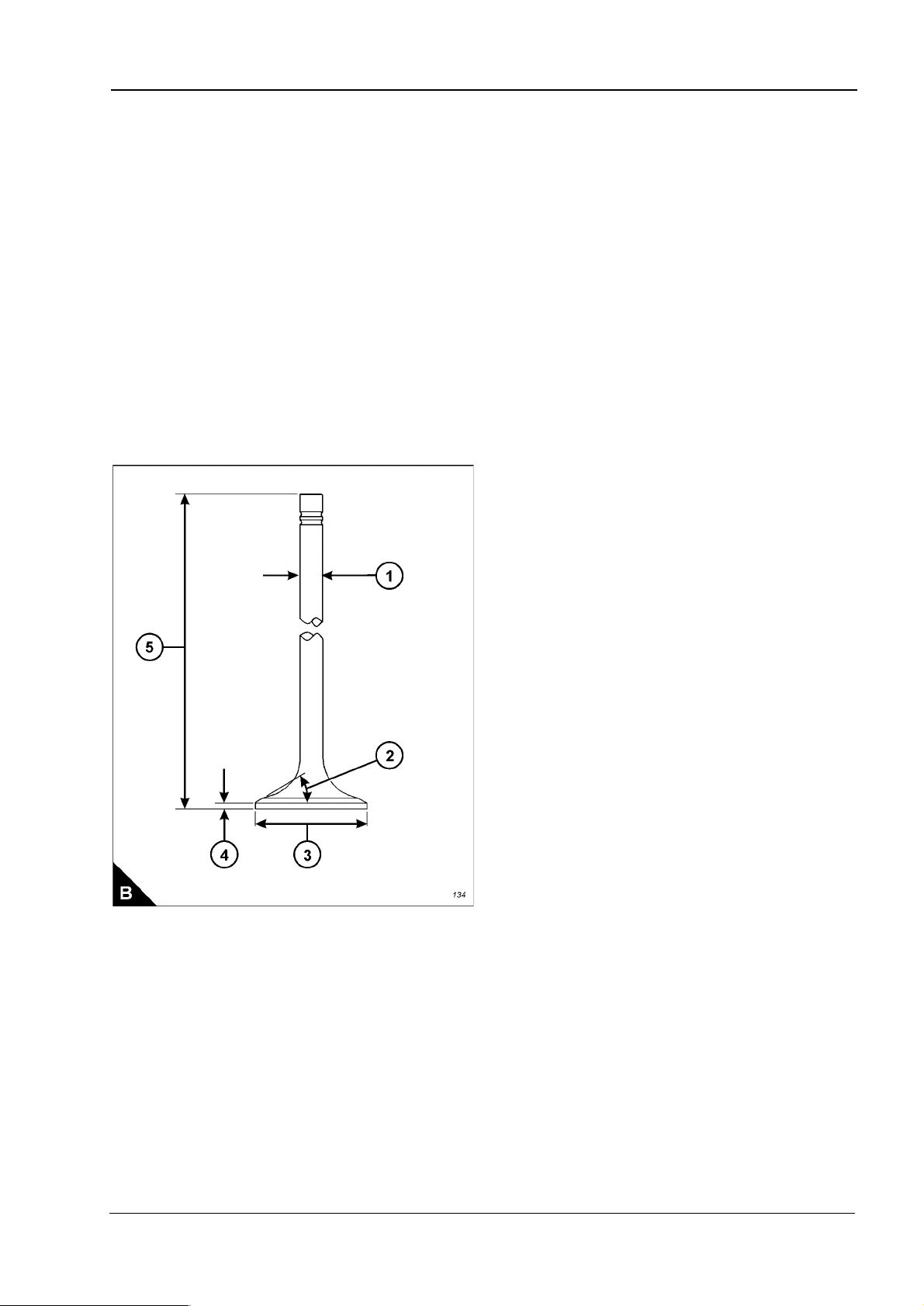
Diameter of valve stem (B1) ... ... ... ... ... ... ... ... ... ... ... ... ... ... ... 9,441 +/- 0,010 mm (0.3717 +/- 0.0004 in)
Permissible worn dimension ... ... ... ... ... ... ... ... ... ... ... ... ... ... ... ... ... ... ... ... ... ... ... 9,408 mm (0.3704 in)
Diameter of valve head (B3):
Inlet valve ... ... ... ... ... ... ... ... ... ... ... ... ... ... ... ... ... ... ... ... ... ... ... . 47,00 +/- 0,13 mm (1.850 +/- 0.005 in)
Exhaust valve .. ... ... ... ... ... ... ... ... ... ... ... ... ... ... ... ... ... ... ... ... ... . 41,81 +/- 0,13 mm (1.646 +/- 0.005 in)
Angle of face of valve (B2):
Inlet valve ... ... ... ... ... ... ... ... ... ... ... ... ... ... ... ... ... ... ... ... ... ... ... ... ... ... ... ... ... ...29 1/4 +/- 1/4 degrees
Exhaust valve .. ... ... ... ... ... ... ... ... ... ... ... ... ... ... ... ... ... ... ... ... ... ... ... ... ... ... ... ...44 1/4 +/- 1/4 degrees
Minimum thickness of valve lip (B4):
Inlet valve ... ... ... ... ... ... ... ... ... ... ... ... ... ... ... ... ... ... ... ... ... ... ... ... ... ... ... ... ... ... ... 2,75 mm (0.108 in)
Exhaust valve .. ... ... ... ... ... ... ... ... ... ... ... ... ... ... ... ... ... ... ... ... ... ... ... ... ... ... ... ... ... 2,05 mm (0.081 in)
Length of valve:
Inlet.. ... ... ... ... ... ... ... ... ... ... ... ... ... ... ... ... ... ... ... ... ... ... ... ... ... 202,00 +/- 0,45 mm (7.953 +/- 0.018 in)
Exhaust ... ... ... ... ... ... ... ... ... ... ... ... ... ... ... ... ... ... ... ... ... ... ... ... 202,06 +/- 0,45 mm (7.955 +/- 0.018 in)
Workshop Manual, TSD3455E, Issue 1 9
Page 20
2
This document has been printed from SPI². Not for Resale
2300
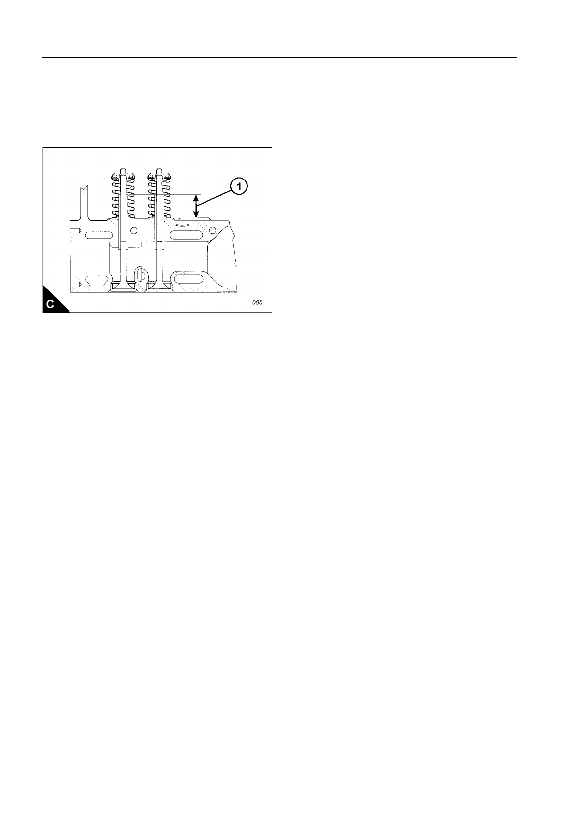
Valve guides
Bore of valve guide when installed ... ... ... ... ... ... ... ... ... ... ... ... ...9,487 +/- 0,025 mm (0.3735 +/- 0.010 in)
Maximum permissible dimension... ... ... ... ... ... ... ... ... ... ... ... ... ... ... ... ... ... ... ... ... ..9,538 mm (0.3755 in)
Do not use a combination of a valve and valve guide which have a difference of 0,13 mm (0.005 in) or more.
Height from cylinder head to top of valve guide (C1). ... ... ... ... ... ... ...35,00 +/- 0,50 mm (1.378 +/- 0.020 in)
Valve springs
Inner
Assembled length .. ... ... ... ... ... ... ... ... ... ... ... ... ... ... ... ... ... ... ... ... ... ... ... ... ... ... ... 60,14 mm (2.368 in)
Load at assembled length.. ... ... ... ... ... ... ... ... ... ... ... ... ... ... ... ... ... ... ... ... ... ... ..118
Minimum operating length.. ... ... ... ... ... ... ... ... ... ... ... ... ... ... ... ... ... ... ... ... ... ... ... ... 44,02 mm (1.733 in)
Load at minimum operating length. ... ... ... ... ... ... ... ... ... ... ... ... ... ... ... ... ... ... ... ..356
Free length after test.. ... ... ... ... ... ... ... ... ... ... ... ... ... ... ... ... ... ... ... ... ... ... ... ... ... ... 71,03 mm (2.797 in)
Outside diameter ... ... ... ... ... ... ... ... ... ... ... ... ... ... ... ... ... ... ... ... ... ... ... ... ... ... ... ... 25,20 mm (0.992 in)
Outer
Assembled length .. ... ... ... ... ... ... ... ... ... ... ... ... ... ... ... ... ... ... ... ... ... ... ... ... ... ... ... 67,12 mm (2.643 in)
Load at assembled length.. ... ... ... ... ... ... ... ... ... ... ... ... ... ... ... ... ... ... ... ... ... ... ..248
Minimum operating length.. ... ... ... ... ... ... ... ... ... ... ... ... ... ... ... ... ... ... ... ... ... ... ... ... 51,00 mm (2.008 in)
Load at minimum operating length. ... ... ... ... ... ... ... ... ... ... ... ... ... ... ... ... ... ... ... 756
Free length after test.. ... ... ... ... ... ... ... ... ... ... ... ... ... ... ... ... ... ... ... ... ... ... ... ... ... ... 77,88 mm (3.066 in)
Outside diameter ... ... ... ... ... ... ... ... ... ... ... ... ... ... ... ... ... ... ... ... ... ... ... ... ... ... ... ... 36,30 mm (1.429 in)
+/- 12 N (27 +/- 3 lb)
+/- 18 N (80 +/- 4 lb)
+/- 25 N (56 +/- 6 lb)
+/- 35 N (165 +/- 8 lb)
10 Workshop Manual, TSD3455E, Issue 1
Page 21
2300
This document has been printed from SPI². Not for Resale
2
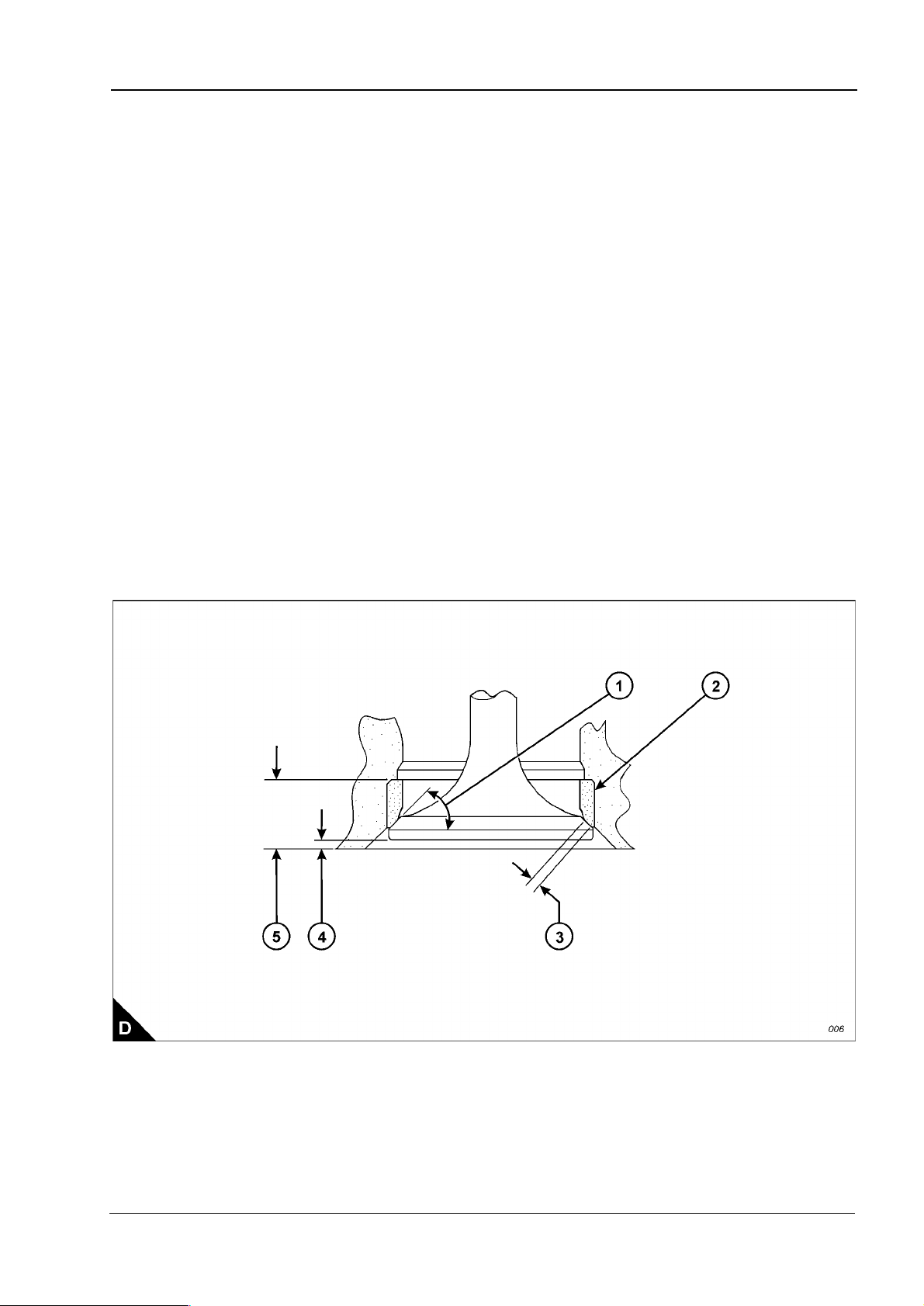
Valve seat inserts
Depth of bore in cylinder head for valve seat insert (D5):
Inlet valve ... ... ... ... ... ... ... ... ... ... ... ... ... ... ... ... ... ... ... ... ... ... ... . 14,00 +/- 0,10 mm (0.551 +/- 0.004 in)
Exhaust valve .. ... ... ... ... ... ... ... ... ... ... ... ... ... ... ... ... ... ... ... ... ... . 13,90 +/- 0,10 mm (0.547 +/- 0.004 in)
Diameter of valve seat insert (D2):
Inlet valve ... ... ... ... ... ... ... ... ... ... ... ... ... ... ... ... ... ... ... ... ... ... 48,025 +/- 0,13 mm (1.8907 +/- 0.0005 in)
Exhaust valve .. ... ... ... ... ... ... ... ... ... ... ... ... ... ... ... ... ... ... ... ... 42,840 +/- 0,13 mm (1.6866 +/- 0.0005 in)
Bore in cylinder head for valve seat insert (D2):
Inlet valve ... ... ... ... ... ... ... ... ... ... ... ... ... ... ... ... ... ... ... ... ... . 47,950 +/- 0,025 mm (1.8878 +/- 0.0010 in)
Exhaust valve .. ... ... ... ... ... ... ... ... ... ... ... ... ... ... ... ... ... ... ... . 42,774 +/- 0,025 mm (1.6840 +/- 0.0010 in)
Angle of face of valve seat insert (D1):
Inlet valve insert... ... ... ... ... ... ... ... ... ... ... ... ... ... ... ... ... ... ... ... ... ... ... ... ... ... ... ...30 1/4 +/- 1/2 degrees
Exhaust valve insert ... ... ... ... ... ... ... ... ... ... ... ... ... ... ... ... ... ... ... ... ... ... ... ... ... ...45 1/4 +/- 1/2 degrees
Valve recess (D4):
Inlet valve (new parts) . ... ... ... ... ... ... ... ... ... ... ... ... ... ... ... ... ... ... ... ..2,20 to 2,80 mm (0.087 to 0.110 in)
Exhaust valve (new parts)... ... ... ... ... ... ... ... ... ... ... ... ... ... ... ... ... ... ..1,20 to 1,80 mm (0.047 to 0.071 in)
Inlet valve (reconditioned parts) .. ... ... ... ... ... ... ... ... ... ... ... ... ... ... ... ..2,20 to 3,29 mm (0.087 to 0.129 in)
Exhaust valve (reconditioned parts) ... ... ... ... ... ... ... ... ... ... ... ... ... ... ..1,20 to 2,29 mm (0.047 to 0.090 in)
Minimum recommended width of valve seat (D3):
Inlet.. ... ... ... ... ... ... ... ... ... ... ... ... ... ... ... ... ... ... ... ... ... ... ... ... ... ... ... ... ... ... ... ... ... 2,00 mm (0.079 in)
Exhaust ... ... ... ... ... ... ... ... ... ... ... ... ... ... ... ... ... ... ... ... ... ... ... ... ... ... ... ... ... ... ... ... 1,25 mm (0.049 in)
Workshop Manual, TSD3455E, Issue 1 11
Page 22
2
This document has been printed from SPI². Not for Resale
2300
Cylinder head
Thickness of cylinder head (new) .. ... ... ... ... ... ... ... ... ... ... ... ... ... .120,00 +/- 0,15 mm (4.724 +/- 0.006 in)
Minimum thickness for a used cylinder head. ... ... ... ... ... ... ... ... ... ... ... ... ... ... ... ... ..119,50 mm (4.705 in)
Flatness of cylinder head: The cylinder head must be flat to within a total of 0,13 mm (0.005 in). Additionally,
the cylinder head must be flat within a maximum of 0,03 mm (0.001 in) across any 76,2 mm (3.00 in) span.
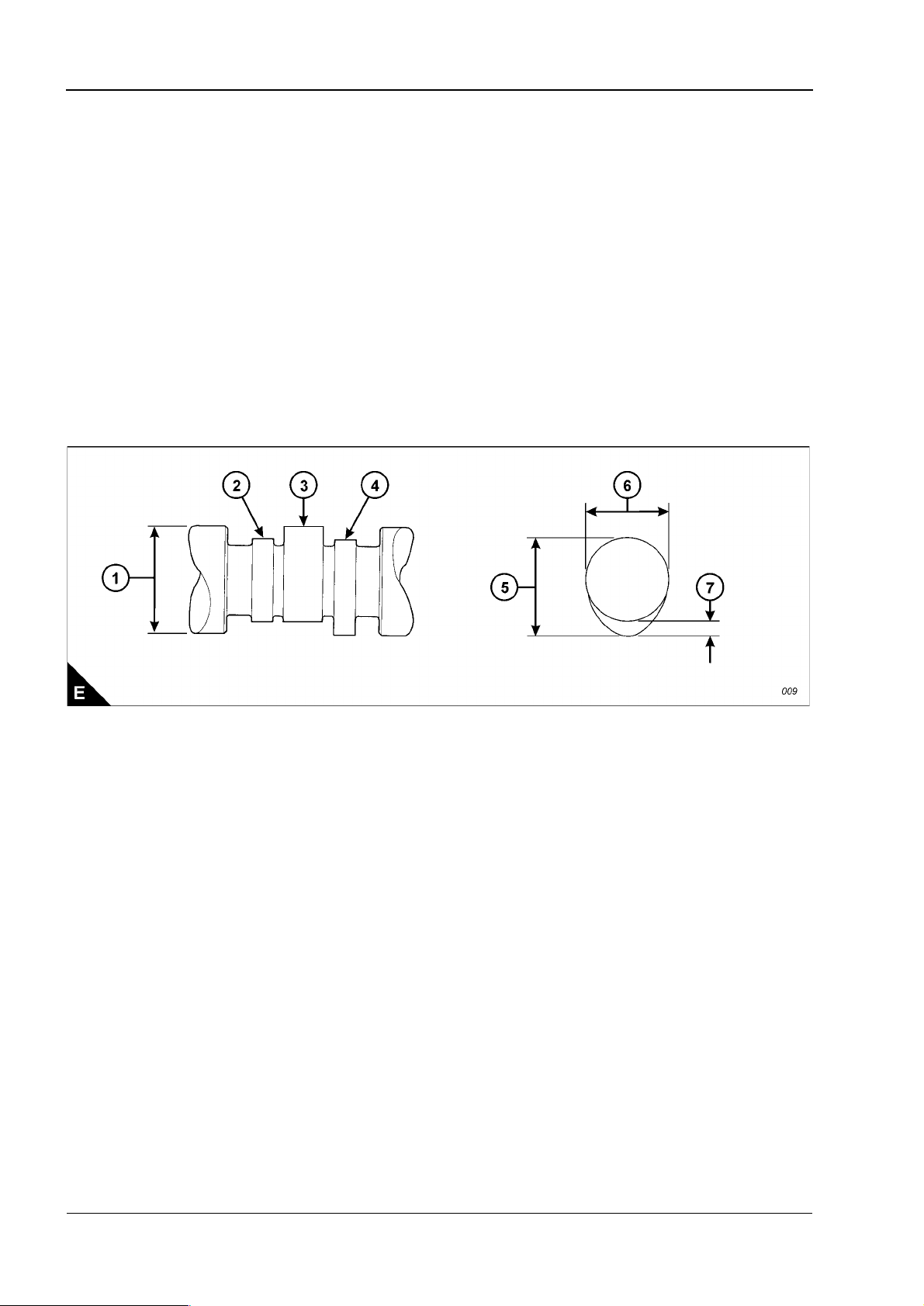
Camshaft and bearings
Diameter of camshaft journal (E3) . ... ... ... ... ... ... ... ... ... ... ... ... ... ... 84,85 +/- 0,02 mm (3.341+/- 0.001 in)
Exhaust lobe lift.. ... ... ... ... ... ... ... ... ... ... ... ... ... ... ... ... ... ... ... ... ... ... ... ... ... ... ... ..8,515 mm (0.3352 in)
Inlet lobe lift ... ... ... ... ... ... ... ... ... ... ... ... ... ... ... ... ... ... ... ... ... ... ... ... ... ... ... ... ... ..9,431 mm (0.3713 in)
Injector lobe lift... ... ... ... ... ... ... ... ... ... ... ... ... ... ... ... ... ... ... ... ... ... ... ... ... ... ... ... 10,451 mm (0.4114 in)
Maximum permissible difference between the actual lobe lift (E7)
and the specified dimension .. ... ... ... ... ... ... ... ... ... ... ... ... ... ... ... ... ... ... ... ... ... ... ... ..1,0 mm (0.0394 in)
To obtain the lobe lift (E7) proceed as follows: Measure the lobe height (E5) and measure the base circle (E6).
Subtract the base circle from the lobe height to give the lobe lift.
12 Workshop Manual, TSD3455E, Issue 1
Page 23
2300
This document has been printed from SPI². Not for Resale
2
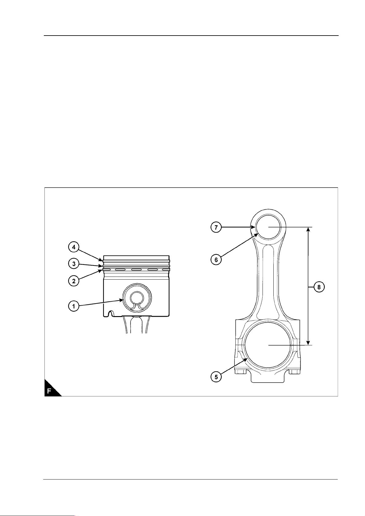
Pistons and connecting rods - 2306 engine
Piston ring gaps measured with the ring fitted in a new liner with a bore size 137.16 mm (5.400 in):
Top piston ring (F4) . ... ... ... ... ... ... ... ... ... ... ... ... ... ... ... ... ... ... ... ... 0,55 +/- 0,15 mm (0.022 +/- 0.006 in)
Intermediate ring (F3).. ... ... ... ... ... ... ... ... ... ... ... ... ... ... ... ... ... ... ... 0,83 +/- 0,15 mm (0.033 +/- 0.006 in)
Oil control ring (F2).. ... ... ... ... ... ... ... ... ... ... ... ... ... ... ... ... ... ... ... 0,550 +/- 0,15 mm (0.022 +/- 0.00 59 in)
Width of groove for oil control ring in new piston. ... ... ... ... ... ... ... ... . 4,03 +/- 0,01 mm (0.159 +/- 0.0004 in)
Thickness of a new oil control ring .. ... ... ... ... ... ... ... ... ... ... ... ... ... 3,98 +/- 0,01 mm (0.1567 +/- 0.0004 in)
Clearance between piston ring groove and new oil control ring.. ... ... . 0,05 +/- 0,02 mm (0.002 +/- 0.0008 in)
Maximum permissible clearance between piston
ring groove and a used oil control ring ... ... ... ... ... ... ... ... ... ... ... ... ... ... ... ... ... ... ... ... 0,15 mm (0.006 in)
Bore of piston crown bearing (F1) ... ... ... ... ... ... ... ... ... ... ... . 55,0355 +/- 0,0055 mm (2.1667 +/- 0.0002 in)
Bore of piston skirt bearing (F1) .. ... ... ... ... ... ... ... ... ... ... ... ... . 55,020 +/- 0,005 mm (2.1661 +/- 0.0002 in)
Gudgeon pin diameter (F1) . ... ... ... ... ... ... ... ... ... ... ... ... ... ... . 55,000 +/- 0,005 mm (2.1654 +/- 0.0002 in)
Length of gudgeon pin. ... ... ... ... ... ... ... ... ... ... ... ... ... ... ... ... ... ... 113,20 +/- 0,15 mm (4.457 +/- 0.006 in)
Bore in connecting rod for small end bearing (F7) .. ... ... ... ... ... . 59,640 +/- 0,013 mm (2.3480 +/- 0.0005 in)
Bore of connecting rod small end bearing (F6) ... ... ... ... ... ... ... . 55,035 +/- 0,008 mm (2.1667 +/- 0.0003 in)
Bore in connecting rod for big end bearing shells (F5) ... ... ... ... . 96,200 +/- 0,013 mm (3.7874 +/- 0.0005 in)
Distance between centres of big and small end bearings (F8) ... ... . 261,62 +/- 0,05 mm (10.300 +/- 0.002 in)
Workshop Manual, TSD3455E, Issue 1 13
Page 24
2
This document has been printed from SPI². Not for Resale
2300
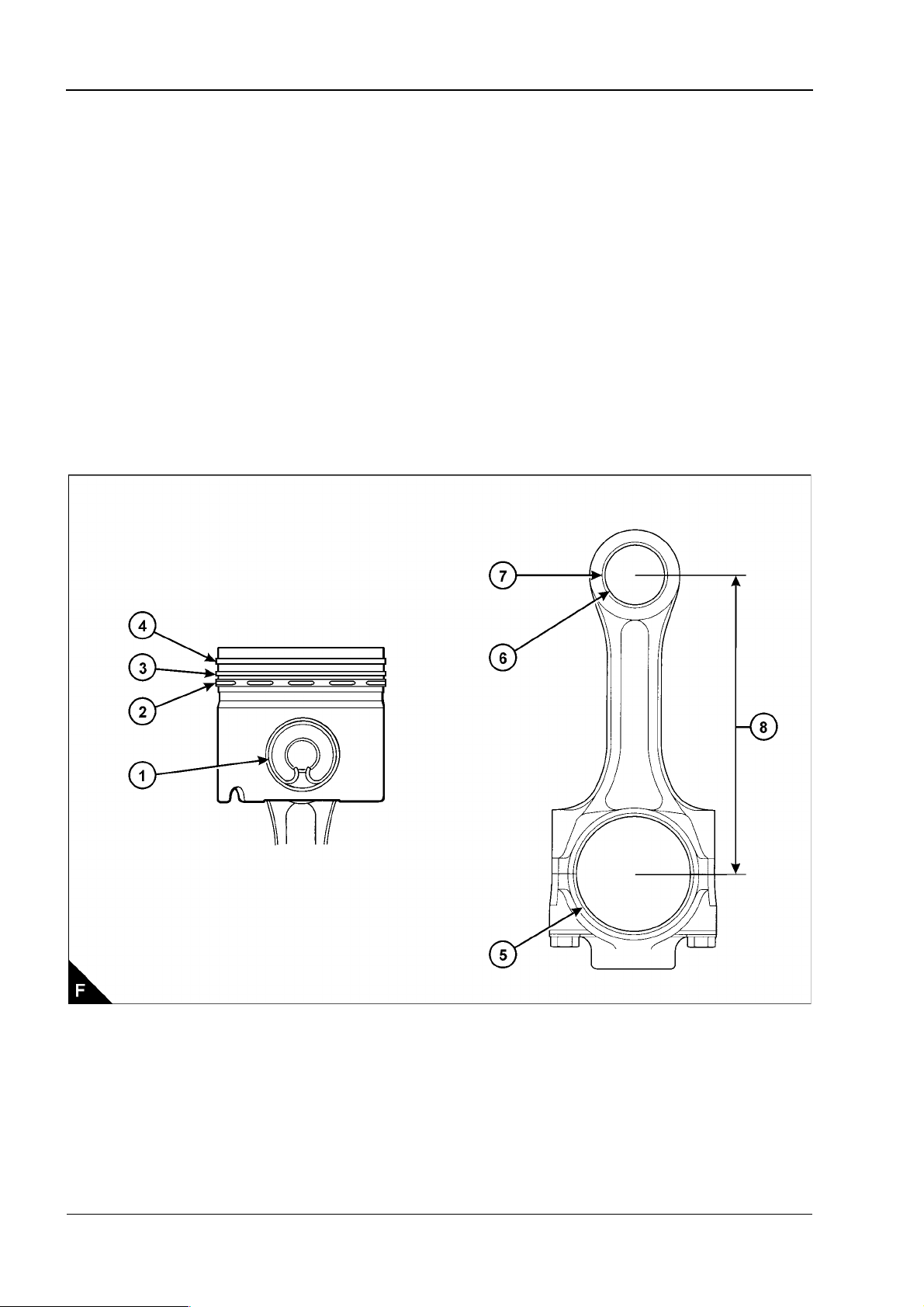
Pistons and connecting rods - 2806 engine
Piston ring gaps measured with the ring fitted in a new liner with a bore size 139,66 mm (5.498 in):
Top piston ring (F4) ... ... ... ... ... ... ... ... ... ... ... ... ... ... ... ... ... ... ... ... .0,50 +/- 0,10 mm (0.020 +/- 0.004 in)
Intermediate ring (F3) ... ... ... ... ... ... ... ... ... ... ... ... ... ... ... ... ... ... ... .0,83 +/- 0,15 mm (0.033 +/- 0.006 in)
Oil control ring (F2) ... ... ... ... ... ... ... ... ... ... ... ... ... ... ... ... ... ... .0,450 +/- 0,150 mm (0.0177 +/- 0.0059 in)
Width of groove for oil control ring in new piston... ... ... ... ... ... ... .4,033 +/- 0,013 mm (0.1588 +/- 0.0005 in)
Thickness of a new oil control ring. ... ... ... ... ... ... ... ... ... ... ... ... .3,980 +/- 0,010 mm (0.1567 +/- 0.0004 in)
Clearance between piston ring groove and new oil control ring ... .0,053 +/- 0,023 mm (0.0021 +/- 0.0009 in)
Maximum permissible clearance between piston
ring groove and a used oil control ring... ... ... ... ... ... ... ... ... ... ... ... ... ... ... ... ... ... ... ... ..0,15 mm (0.006 in)
Bore of piston crown bearing (F1).. ... ... ... ... ... ... ... ... ... ... ...55,0355 +/- 0,0055 mm (2.1667 +/- 0.0002 in)
Bore of piston skirt bearing (F1). ... ... ... ... ... ... ... ... ... ... ... ... ...55,020 +/- 0,005 mm (2.1661 +/- 0.0002 in)
Gudgeon pin diameter (F1) ... ... ... ... ... ... ... ... ... ... ... ... ... ... ...55,000 +/- 0,005 mm (2.1654 +/- 0.0002 in)
Length of gudgeon pin... ... ... ... ... ... ... ... ... ... ... ... ... ... ... ... ... ... .113,20 +/- 0,15 mm (4.457 +/- 0.006 in)
Bore in connecting rod for small end bearing (F7). ... ... ... ... ... ... 59,640 +/- 0,013 mm (2.3480 +/- 0.0005 in)
Bore of connecting rod small end bearing (F6).. ... ... ... ... ... ... ...55,035 +/- 0,008 mm (2.1667 +/- 0.0003 in)
Bore in connecting rod for big end bearing shells (F5).. ... ... ... ...96,200 +/- 0,013 mm (3.7874 +/- 0.0005 in)
Distance between centres of big and small end bearings (F8).. ... ...261,62 +/- 0,05 mm (10.300 +/- 0.002 in)
14 Workshop Manual, TSD3455E, Issue 1
Page 25
2300
This document has been printed from SPI². Not for Resale
2
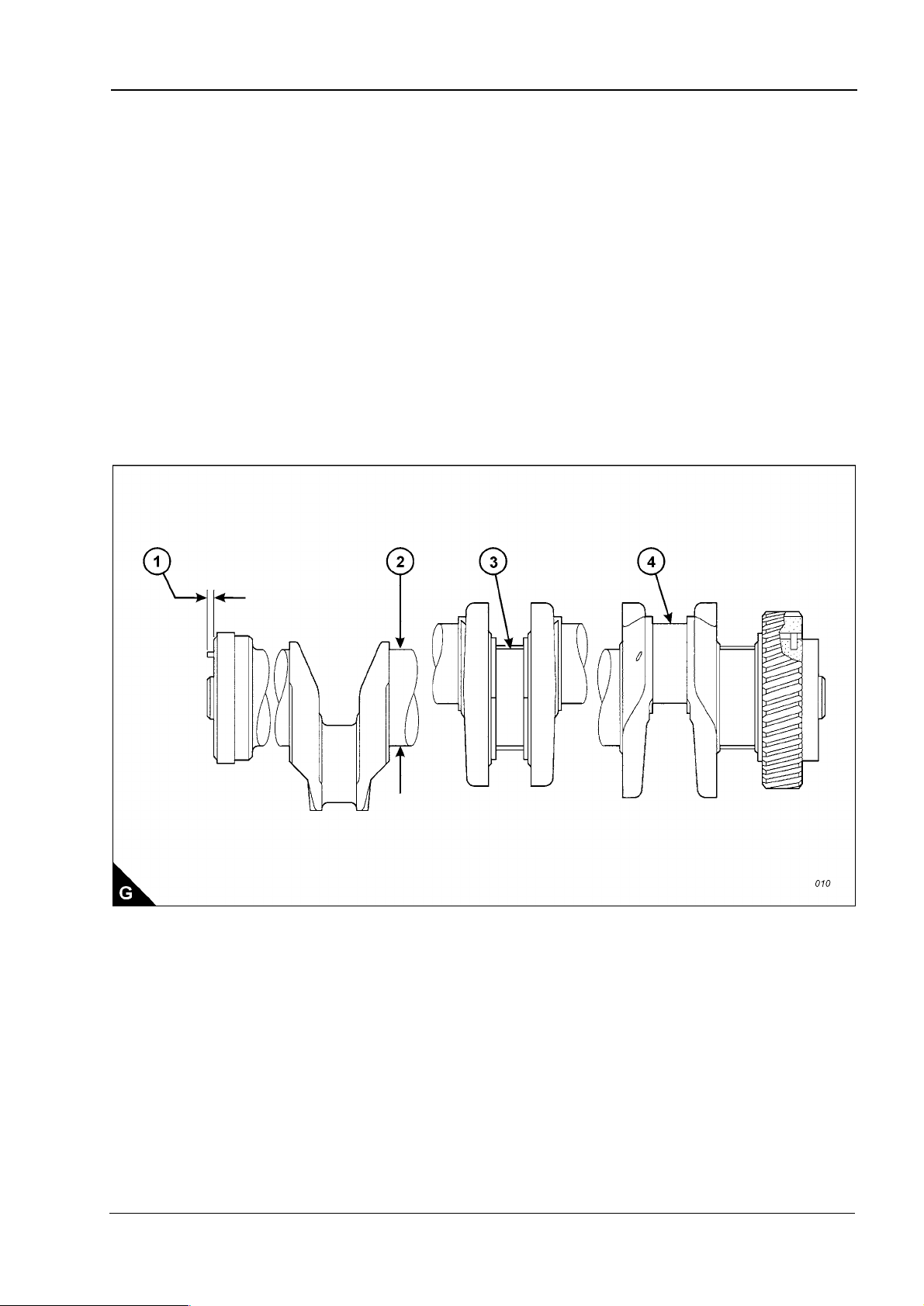
Crankshaft, main bearings and flywheel
Diameter of main bearing journal (G2) ... ... ... ... ... ... ... ... ... ... 120,650 +/- 0,020 mm (4.7500 +/- 0.0008 in)
Journal undersize by 0,63 mm (0.025 in) ... ... ... ... ... ... ... ... ... ... .. 120,015 +/- 0,020 (4.7250 +/- 0.0008 in)
Journal undersize by 1,27 mm (0.050 in) ... ... ... ... ... ... ... ... ... 119,380 +/- 0,020 mm (4.7000 +/- 0.0008 in)
Clearance between a new bearing and the journal (G3). ... ... ... ... ..0,091 to 0,186 mm (0.0036 to 0.0073 in)
Maximum permissible clearance between the
bearing and journal.. ... ... ... ... ... ... ... ... ... ... ... ... ... ... ... ... ... ... ... ... ... ... ... ... ... ... ... 0,25 mm (0.010 in)
Diameter of main bearing bore ... ... ... ... ... ... ... ... ... ... ... ... ... 129,891 +/- 0,013 mm (5.1138 +/- 0.0005 in)
Diameter of main bearing bore, oversize by 0,63 mm (0.025 in). 130,526 +/- 0,013 mm (5.1388 +/- 0.0005 in)
Diameter of connecting rod journal (G4) . ... ... ... ... ... ... ... ... ... . 90,000 +/- 0,020 mm (3.5433 +/- 0.0008 in)
Journal undersize by 0,63 mm (0.025 in) ... ... ... ... ... ... ... ... ... ... ... 89,370 +/- 0,020 (3.5185 +/- 0.0008 in)
Journal undersize by 1,27 mm (0.050 in) ... ... ... ... ... ... ... ... ... . 88,730 +/- 0,020 mm (3.4933 +/- 0.0008 in)
Clearance between a new bearing and the journal. ... ... ... ... ... ... ..0,062 to 0,160 mm (0.0024 to 0.0063 in)
Maximum permissible clearance between the
bearing and journal.. ... ... ... ... ... ... ... ... ... ... ... ... ... ... ... ... ... ... ... ... ... ... ... ... ... ... ... 0,20 mm (0.008 in)
End-float of crankshaft. ... ... ... ... ... ... ... ... ... ... ... ... ... ... ... ... ... ... ... ..0,15 to 0,55 mm (0.006 to 0.022 in)
Maximum permissible end-float (with used bearings) . ... ... ... ... ... ... ... ... ... ... ... ... ... ... 0,89 mm (0.035 in)
Maximum protrusion of dowel (G1) . ... ... ... ... ... ... ... ... ... ... ... ... ... ... ... ... ... ... ... ... ... ... 6,4 mm (0.25 in)
Crankshaft damper
Maximum permissible run-out of face of damper ... ... ... ... ... ... ... ... ... ... ... ... ... ... ... ... 2,03 mm (0.080 in)
Workshop Manual, TSD3455E, Issue 1 15
Page 26
2
This document has been printed from SPI². Not for Resale
2300
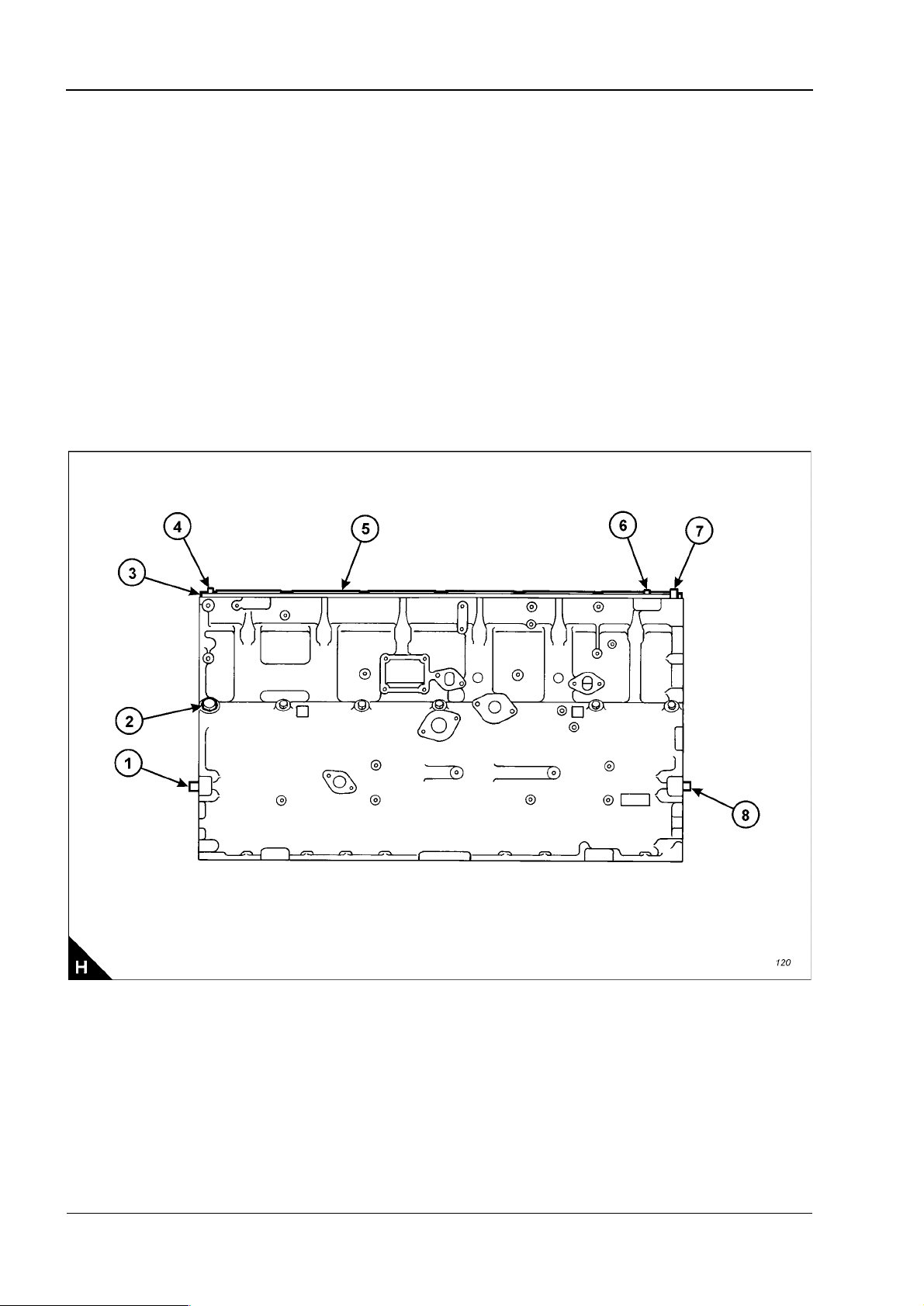
Crankcase and cylinder liners
Thickness of spacer plate (H3).. ... ... ... ... ... ... ... ... ... ... ... ... ... .8,585 +/- 0,025 mm (0.3380 +/- 0.0010 in)
Thickness of gasket fitted between spacer plate and crankcase... .0,238 +/- 0,032 mm (0.0094 +/- 0.0013 in)
Cylinder liner protrusion (H5) above the spacer plate ... ... ... ... ... ... 0,025 to 0,152 mm (0.0010 to 0.0060 in)
Maximum variation in each cylinder liner... ... ... ... ... ... ... ... ... ... ... ... ... ... ... ... ... ... ..0,051 mm (0.0020 in)
Maximum average variation between adjacent cylinder liners... ... ... ... ... ... ... ... ... ... ..0,051 mm (0.0020 in)
Maximum variation between all cylinder liners... ... ... ... ... ... ... ... ... ... ... ... ... ... ... ... ..0,102 mm (0.0040 in)
Refer to Operation 7-3 for further cylinder liner information.
Protrusion of front cylinder head dowel (H6) above top face of crankcase ...16,0 +/- 0,5 mm (0.63 +/- 0.02 in)
Protrusion of rear cylinder head dowel (H4) above top face of crankcase ...18,5 +/- 0,5 mm (0.73 +/- 0.02 in)
Protrusion of oil transfer tube (H7) above top face of crankcase... ... ... ... ...20,0 +/- 0,5 mm (0.79 +/- 0.02 in)
Protrusion of flywheel housing dowels (H1) from rear face of crankcase.. ...19,1 +/- 0,5 mm (0.75 +/- 0.02 in)
Protrusion of gear case dowels (H8) from front face of crankcase ... ... ... ...19,1 +/- 0,5 mm (0.75 +/- 0.02 in)
Plug (H2) must be tightened to a torque of ... ... ... ... ... ... ... ... ... ... ... ... ... ... ... 70 +/- 10 Nm (52 +/- 7 lbf ft)
The total flatness of the top face of the crankcase must be within 0,10 mm (0.004 in). The flatness must also
be within 0,05 mm (0.002 in) for any 177,5 mm (6.99 in) section of the surface.
Continued
16 Workshop Manual, TSD3455E, Issue 1
Page 27
2300
This document has been printed from SPI². Not for Resale
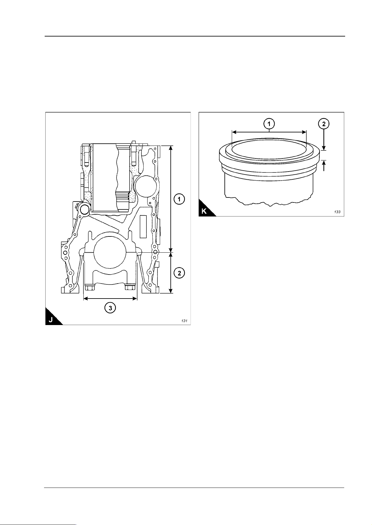
Distance from top of crankcase to centre of main
bearing bore (J1) . ... ... ... ... ... ... ... ... ... ... ... ... ... ... ... ... ... ... ... . 425,45 +/- 0,15 mm (16.750 +/- 0.006 in)
Minimum permissible (J1) ... ... ... ... ... ... ... ... ... ... ... ... ... ... ... ... ... ... ... ... ... ... ... ..425,02 mm (16.733 in)
Distance f rom bottom of crankcase to centre of main
bearing bore (J2) . ... ... ... ... ... ... ... ... ... ... ... ... ... ... ... ... ... ... ... ... 165,10 +/- 0,10 mm (6.500 +/- 0.004 in)
Bore in new cylinder liner - 2306 engine (K1).. ... ... ... ... ... ... ... 137,185 +/- 0,025 mm (5.4010 +/- 0.0010 in)
Bore in new cylinder liner - 2806 engine (K1).. ... ... ... ... ... ... ... 139,685 +/- 0,025 mm (5.4994 +/- 0.0010 in)
Thickness of liner flange (K2).. ... ... ... ... ... ... ... ... ... ... ... ... ... ... 8,890 +/- 0,020 mm (0.3500 +/- 0.0008 in)
Minimum thickness permissible (K2)... ... ... ... ... ... ... ... ... ... ... ... ... ... ... ... ... ... ... ... 8,870 mm (0.3492 in)
2
Workshop Manual, TSD3455E, Issue 1 17
Page 28
2
This document has been printed from SPI². Not for Resale
2300
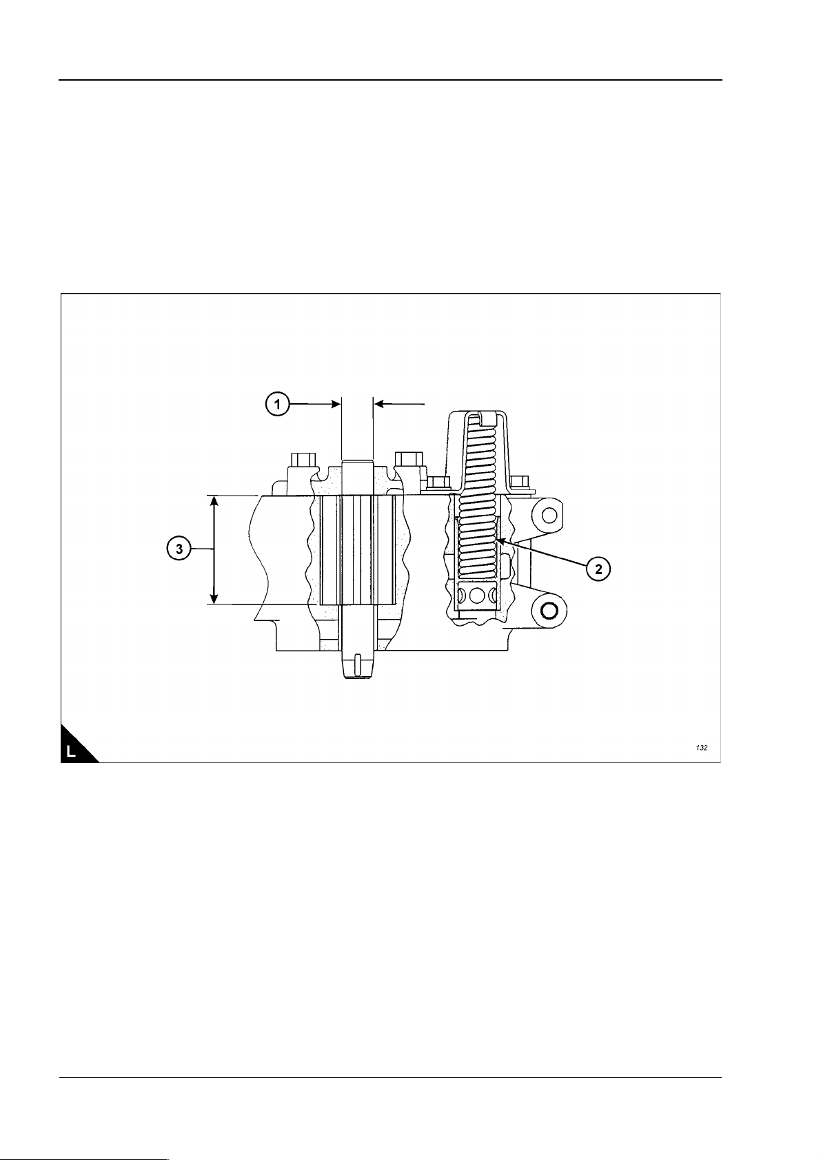
Lubricating oil pump
Diameter of shafts (L1) .. ... ... ... ... ... ... ... ... ... ... ... ... ... ... ... ...22,217 +/- 0,005 mm (0.8747 +/- 0.0002 in)
Diameter of bores in cover for shafts. ... ... ... ... ... ... ... ... ... ... ...22,258 +/- 0,008 mm (0.8763 +/- 0.0003 in)
Length of gears (L3)... ... ... ... ... ... ... ... ... ... ... ... ... ... ... ... ... ... 79,375 +/- 0,025 mm (3.1250 +/- 0.0010 in)
Depth of bores for gears (L3). ... ... ... ... ... ... ... ... ... ... ... ... ... ...79,502 +/- 0,020 mm (3.1300 +/- 0.0008 in)
Spring (L2):
Test force... ... ... ... ... ... ... ... ... ... ... ... ... ... ... ... ... ... ... ... ... ... ... ... ... ... ... . 150 +/- 8 Nm (110 +/- 6 lbf ft)
Length under test force.. ... ... ... ... ... ... ... ... ... ... ... ... ... ... ... ... ... ... ... ... ... ... ... ... ... ..117,9 mm (4.64 in)
Free length after test.. ... ... ... ... ... ... ... ... ... ... ... ... ... ... ... ... ... ... ... ... ... ... ... ... ... ... ..152,9 mm (6.02 in)
Outside diameter ... ... ... ... ... ... ... ... ... ... ... ... ... ... ... ... ... ... ... ... ... ... ... ... ... ... ... ... ... .27 mm (1.063 in)
18 Workshop Manual, TSD3455E, Issue 1
Page 29
2300
This document has been printed from SPI². Not for Resale
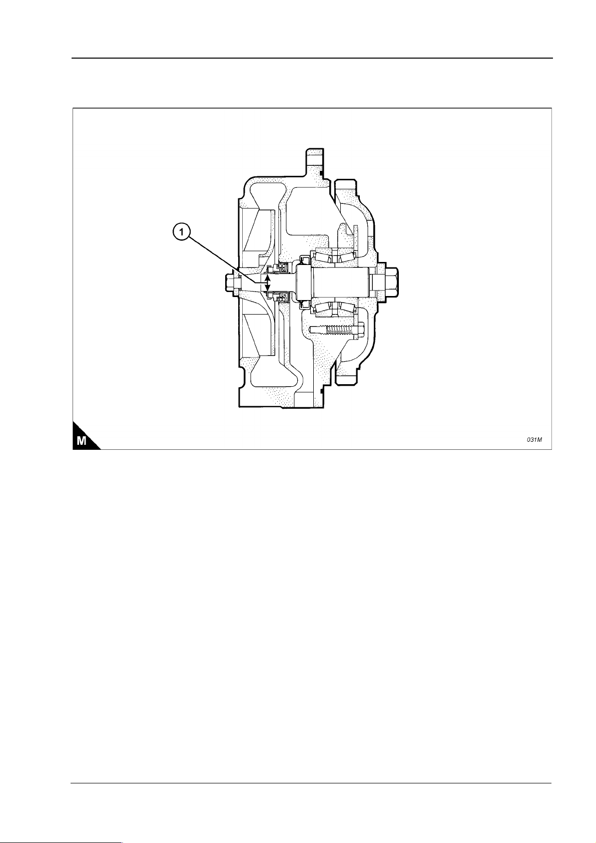
Coolant pump
Shaft diameter at the position of the coolant seal (M1) ... ... ... ... ... . 19,10 +/- 0,01 mm (0.7520 +/- 0.0004 in)
2
Workshop Manual, TSD3455E, Issue 1 19
Page 30

2
This document has been printed from SPI². Not for Resale
2300
Recommended torque figures
Exceptions to these torque figures are given in the Workshop Manual where necessary.
Before any components are fitted to the engine, ensure that they are in a new or close to new condition. Bolts
or threads must not be worn or damaged. Components must be free from rust or other corrosion. Clean with
a non-corrosive cleaner if necessary. Do not lubricate the threads of fasteners. Rust preventative which has
been applied by the component supplier for shipping and storage is acceptable. Certain components may
require an application of a particular lubricant, details are given in the Workshop Manual where relevant.
Standard torque figures for metric fasteners
Metric nuts and bolts
Thread size
metric
M6 12 +/- 3 Nm (9 +/- 2 lbf ft)
M8 28 +/- 7 Nm (21 +/- 5 lbf ft)
M10 55 +/- 10 Nm (41 +/- 7 lbf ft)
M12 100 +/- 20 Nm (75 +/- 15 lbf ft)
M14 160 +/- 30 Nm (120 +/- 22 lbf ft)
M16 240 +/- 40 Nm (175 +/- 30 lbf ft)
M20 460 +/- 60 Nm (340 +/- 44 lbf ft)
M24 800 +/- 100 Nm (590 +/- 75 lbf ft)
M30 1600 +/- 200 Nm (1180 +/- 150 lbf ft)
M36 2700 +/- 300 Nm (2000 +/- 220 lbf ft)
Standard torque
Metric taperlock studs
Thread size
metric
M6 8 +/- 3 Nm (6 +/- 2 lbf ft)
M8 17 +/- 5 Nm (13 +/- 4 lbf ft)
M10 35 +/- 5 Nm (26 +/- 4 lbf ft)
M12 65 +/- 10 Nm (48 +/- 7 lbf ft)
M16 110 +/- 20 Nm (80 +/- 15 lbf ft)
M20 170 +/- 30 Nm (125 +/- 22 lbf ft)
M24 400 +/- 60 Nm (300 +/- 44 lbf ft)
M30 750 +/- 80 Nm (550 +/- 60 lbf ft)
M36 1200 +/- 150 Nm (880 +/- 110 lbf ft)
Standard torque
20 Workshop Manual, TSD3455E, Issue 1
Page 31

2300
This document has been printed from SPI². Not for Resale
Standard torque figures for imperial fasteners
Imperial nuts and bolts
Thread size
inches
1/4 12 +/- 3 Nm (9 +/- 2 lbf ft)
5/16 25 +/- 6 Nm (18 +/- 4 lbf ft)
3/8 47 +/- 9 Nm (35 +/- 7 lbf ft)
7/16 70 +/- 15 Nm (50 +/- 11 lbf ft)
1/2 105 +/- 20 Nm (75 +/- 15 lbf ft)
9/16 160 +/- 30 Nm (120 +/- 22 lbf ft)
5/8 215 +/- 40 Nm (160 +/- 30 lbf ft)
3/4 370 +/- 50 Nm (275 +/- 37 lbf ft)
7/8 620 +/- 80 Nm (460 +/- 60 lbf ft)
1 900 +/- 100 Nm (660 +/- 75 lbf ft)
1 1/8 1300 +/- 150 Nm (960 +/- 110 lbf ft)
1 1/4 1800 +/- 200 Nm (1320 +/- 150 lbf ft)
1 3/8 2400 +/- 300 Nm (1780 +/- 220 lbf ft)
1 1/2 3100 +/- 350 Nm (2280 +/- 260 lbf ft)
Imperial taperlock studs
Thread size
inches
1/4 8 +/- 3 Nm (6 +/- 2 lbf ft)
5/16 17 +/- 5 Nm (13 +/- 4 lbf ft)
3/8 35 +/- 5 Nm (26 +/- 4 lbf ft)
7/16 45 +/- 10 Nm (33 +/- 7 lbf ft)
1/2 65 +/- 10 Nm (48 +/- 7 lbf ft)
5/8 110 +/- 20 Nm (80 +/- 15 lbf ft)
3/4 170 +/- 30 Nm (125 +/- 22 lbf ft)
7/8 260 +/- 40 Nm (190 +/- 30 lbf ft)
1 400 +/- 60 Nm (300 +/- 44 lbf ft)
1 1/8 525 +/- 60 Nm (390 +/- 44 lbf ft)
1 1/4 750 +/- 80 Nm (550 +/- 60 lbf ft)
1 3/8 950 +/- 125 Nm (700 +/- 90 lbf ft)
1 1/2 1200 +/- 150 Nm (880 +/- 110 lbf ft)
2
Standard torque
Standard torque
Workshop Manual, TSD3455E, Issue 1 21
Page 32

2
This document has been printed from SPI². Not for Resale
Standard torque figures for ‘O’ ring face seal fittings and 37 degree flared fittings
Torque figures for ferrous straight thread ‘O’ ring fittings when connected to ferrous materials
Outside diameter of nominal tube
3,18 mm
(0.125 in)
4,76 mm
(0.188 in)
6,35 mm
(0.250 in)
7,94 mm
(0.312 in)
9,52 mm
(0.375 in)
12,70 mm
(0.500 in)
15,88 mm
(0.625 in)
19,05 mm
(0.750 in)
22,22 mm
(0.875 in)
25,40 mm
(1.000 in)
31,75 mm
(1.250 in)
38,10 mm
(1.500 in)
50,80 mm
(2.000 in)
Thread size
Inches
5/16 - 24
3/8 - 24
7/16 - 20
1/2 - 20
9/16 - 18
3/4 - 16
7/8 - 14
1 1/16 - 12
1 3/16 - 12
1 5/16 - 12
1 5/8 - 12
1 7/8 - 12
2 1/2 - 12
Standard
torque
5,0 +/- 1,5 Nm
(4 +/- 1 lbf ft)
12 +/- 2 Nm
(9 +/- 1 lbf ft)
22 +/- 2 Nm
(16 +/- 1 lbf ft)
30 +/- 3 Nm
(22 +/- 2 lbf ft)
48 +/- 5 Nm
(35 +/- 4 lbf ft)
82 +/- 8 Nm
(60 +/- 6 lbf ft)
143 +/- 15 Nm
(105 +/- 11 lbf ft)
190 +/- 20 Nm
(140 +/- 15 lbf ft)
250 +/- 25 Nm
(185 +/- 18 lbf ft)
300 +/- 30 Nm
(220 +/- 22 lbf ft)
350 +/- 30 Nm
(260 +/- 22 lbf ft)
430 +/- 40 Nm
(320 +/- 30 lbf ft)
450 +/- 45 Nm
(330 +/- 33 lbf ft)
2300
Note: For the table above, use 50 percent of the torque figure when the fitting, the plug or the port material is
nonferrous.
Examples of relevant fittings are shown (A): ‘O’ ring face seal (A1), 37 degree flare (A2) and plug with a
hexagon or socket-type head (A3).
22 Workshop Manual, TSD3455E, Issue 1
Page 33

2300
This document has been printed from SPI². Not for Resale
‘O’ ring face seal fittings
Torque figures for ferrous straight thread ‘O’ ring fittings (B)
Thread size
inches
1/4 8 +/- 3 Nm (6 +/- 2 lbf ft)
5/16 17 +/- 5 Nm (13 +/- 4 lbf ft)
3/8 35 +/- 5 Nm (26 +/- 4 lbf ft)
7/16 45 +/- 10 Nm (33 +/- 7 lbf ft)
1/2 65 +/- 10 Nm (48 +/- 7 lbf ft)
5/8 110 +/- 20 Nm (80 +/- 15 lbf ft)
3/4 170 +/- 30 Nm (125 +/- 22 lbf ft)
7/8 260 +/- 40 Nm (190 +/- 30 lbf ft)
1 400 +/- 60 Nm (300 +/- 44 lbf ft)
1 1/8 525 +/- 60 Nm (390 +/- 44 lbf ft)
1 1/4 750 +/- 80 Nm (550 +/- 60 lbf ft)
1 3/8 950 +/- 125 Nm (700 +/- 90 lbf ft)
1 1/2 1200 +/- 150 Nm (880 +/- 110 lbf ft)
2
Standards torque
Workshop Manual, TSD3455E, Issue 1 23
Page 34

2
This document has been printed from SPI². Not for Resale
2300
Torque figures for flared and ‘O’ ring fittings
The torque figures given in the table below and the table given on page 17 should be applied to the nut of the
fittings which follow: 37 degree flared fittings (C1), 45 degree flared fittings (C3), inverted flared fittings (C2),
‘O’ ring fittings for a recessed drive, ‘O’ ring fittings for air conditioning and swivel nuts (C2). The figures should
be used for applications which allow these working pressures: 7750 to 34450 kPa (1125 to 5000 lb/in²). The
torque figure depends on the size and type of fitting.
Nuts for 37 degree flared fittings
Outside diameter of nominal tube
3,18 mm
(0.125 in)
4,76 mm
(0.188 in)
6,35 mm
(0.250 in)
7,94 mm
(0.312 in)
9,52 mm
(0.375 in)
9,52 mm
(0.375 in)
12,70 mm
(0.500 in)
15,88 mm
(0.625 in)
19,05 mm
(0.750 in)
22,22 mm
(0.875 in)
25,40 mm
(1.000 in)
31,75 mm
(1.250 in)
38,10 mm
(1.500 in)
50,80 mm
(2.000 in)
Thread size
Inches
5/16
3/8
7/16
1/2
9/16
5/8
3/4
7/8
1 1/16
1 3/16
1 5/16
1 5/8
1 7/8
2 1/2
Standard
torque
5,0 +/- 1,5 Nm
(4 +/- 1 lbf ft)
11 +/- 2 Nm
(8 +/- 1 lbf ft)
16 +/- 4 Nm
(12 +/- 3 lbf ft)
20 +/- 5 Nm
(15 +/- 4 lbf ft)
25 +/- 5 Nm
(18 +/- 4 lbf ft)
35 +/- 5 Nm
(26 +/- 4 lbf ft)
50 +/- 7 Nm
(37 +/- 5 lbf ft)
65 +/- 7 Nm
(48 +/- 5 lbf ft)
100 +/- 10 Nm
(75 +/- 7 lbf ft)
120 +/- 10 Nm
(90 +/- 7 lbf ft)
135 +/- 15 Nm
(100 +/- 11 lbf ft)
180 +/- 15 Nm
(135 +/- 11 lbf ft)
225 +/- 15 Nm
(165 +/- 11 lbf ft)
320 +/- 30 Nm
(240 +/- 22 lbf ft)
Note: For the table above, use 50 percent of the torque figure when the fitting, the plug or the port material is
nonferrous.
24 Workshop Manual, TSD3455E, Issue 1
Page 35

2300
This document has been printed from SPI². Not for Resale
45 degree flared and 45 degree inverted flare fittings
45 degree flared and 45 degree inverted flare fittings
Outside diameter of nominal tube
3,18 mm
(0.125 in)
4,76 mm
(0.188 in)
6,35 mm
(0.250 in)
7,94 mm
(0.312 in)
9,52 mm
(0.375 in)
11,11 mm
(0.438 in)
12,70 mm
(0.500 in)
15,88 mm
(0.625 in)
19,05 mm
(0.750 in)
22,22 mm
(0.875 in)
Thread size
Inches
5/16
3/8
7/16
1/2
5/8
11/16
3/4
7/8
1 1/16
1 1/4
2
Standard
torque
5,0 +/- 1,5 N m
(4 +/- 1 lbf ft)
8 +/- 1,5 Nm
(6 +/- 1 lbf ft)
11 +/- 2 Nm
(8 +/- 1 lbf ft)
17 +/- 3 Nm
(13 +/- 2 lbf ft)
30 +/- 3 Nm
(22 +/- 2 lbf ft)
30 +/- 3 Nm
(22 +/- 2 lbf ft)
38 +/- 4 Nm
(28 +/- 3 lbf ft)
50 +/- 5 Nm
(37 +/- 4 lbf ft)
90 +/- 8 Nm
(65 +/- 6 lbf ft)
100 +/- 10 Nm
(75 +/- 7 lbf ft)
Tapered pipe thread fittings
Tapered pipe thread fittings
Thread size
Inches
1/16 - 27 10 Nm (7 lbf ft) 10 Nm (7 lbf ft)
1/8 - 27 16 Nm (12 lbf ft) 16 Nm (12 lbf ft)
1/4 - 18 20 Nm (15 lbf ft) 25 Nm (18 lbf ft)
3/8 - 18 35 Nm (26 lbf ft) 45 Nm (33 lbf ft)
1/2 - 14 45 Nm (33 lbf ft) 60 Nm (44 lbf ft)
3/4 - 14 60 Nm (44 lbf ft) 75 Nm (55 lbf ft)
1 - 11 1/2 75 Nm (55 lbf ft) 90 Nm (65 lbf ft)
1 1/4 - 11 1/2 90 Nm (65 lbf ft) 110 Nm (80 lbf ft)
1 1/2 - 11 1/2 110 Nm (80 lbf ft) 130 Nm (95 lbf ft)
2 - 11 1/2 130 Nm (95 lbf ft) 160 Nm (120 lbf ft)
Threads with pipe sealant
(CV60891)
Note: For t he t a bl e ab o ve , us e 5 0 p er ce nt o f t he t or q ue f i gu re w h en t he f itting, th e pl ug o r t he po r t m ate r i al i s
nonferrous.
Standard torque
Threads without pipe sealant
Workshop Manual, TSD3455E, Issue 1 25
Page 36

2
This document has been printed from SPI². Not for Resale
Torque figures for standard hose clamps of the worm drive band type
2300
Width of clamp
7,9 mm (0.31 in) 0,9 +/- 0,2 Nm (8 +/- 2 lbf in)
13,5 mm (0.53 in) 4,5 +/- 0,5 Nm (40 +/- 4 lbf in)
15,9 mm (0.63 in) 7,5 +/- 0,5 Nm (65 +/- 4 lbf in)
Width of clamp Torque figure for used clamp
7,9 mm (0.31 in) 0,7 +/- 0,2 Nm (6 +/- 2 lbf in)
13,5 mm (0.53 in) 3,0 +/- 0,5 Nm (27 +/- 4 lbf in)
15,9 mm (0.63 in) 4,5 +/- 0,5 Nm (40 +/- 4 lbf in)
Torque figure for initial
installation on a new hose
Torque figures for constant torque hose clamps
Use a torque wrench for the correct installation of a constant torque hose clamp. For a constant torque hose
clamp to be installed correctly, these conditions must exist:
The screw tip (D1) must extend by 6,35 mm (0.250 in) beyond the housing (D2).
The belleville washers must be collapsed almost flat after the screw (D3) has been tightened to a torque of
11 +/- 1 Nm (98 +/- 9 lb in).
26 Workshop Manual, TSD3455E, Issue 1
Page 37

2300
This document has been printed from SPI². Not for Resale
3
Cylinder head assembly 3
General information
The cylinder head is a single-piece cast iron component. The camshaft is mounted in the cylinder head and
runs in shell bearings. The bearings are pressed into each journal and are lubricated under pressure. Bridge
piece guides have been eliminated as floating valve bridges have been utilised.
Special thermal sleeves manufactured from stainless steel are fitted to the exhaust ports. These reduce the
amount of heat transferred to the cooling system and direct the thermal energy to the turbocharger.
The electronic unit injectors are mounted in stainless steel sleeves which have been pressed into the injector
bores of the cylinder head.
The operations to remove and to fit valve seat inserts and to remove and to fit camshaft bearings are not
included as specialist equipment is required. It is recommended that operators take advantage of the Perkins
service exchange scheme if these procedures become necessary.
Workshop Manual, TSD3455E, Issue 1 27
Page 38

3
This document has been printed from SPI². Not for Resale
2300
Rocker cover
To remove and to fit Operation 3-1
To remove
Warning! The electrical circuit for the fuel injector units operates on 110 volts. Do NOT work on the fuel injector
units unless the power supply to the ECM has been disconnected.
1 Disconnect the wiring harness at the socket on the rocker cover (A1). 2 Disconnect and remove the engine breather pipe (A2). 3 Loosen fully the bolts which retain the rocker cover, but do not remove the bolts from the assembly; allow
them to be retained by the seal.
4 Remove the rocker cover. To fit 1 Inspect the seal of the rocker cover and renew if worn of damaged.
2 Fit the rocker cover, complete with seal and bolts. Tighten the bolts to a torque of 20 Nm (15 lbf ft); use the
sequence shown (B).
3 Fit the engine breather pipe (A2). 4 Connect the wiring harness. Ensure that the wiring harness is fully engaged with the connector.
28 Workshop Manual, TSD3455E, Issue 1
Page 39

2300
This document has been printed from SPI². Not for Resale
3
Rocker lever and rocker shaft assemblies
To remove and to fit Operation 3-2
To remove 1 Remove the rocker cover, Operation 3-1.
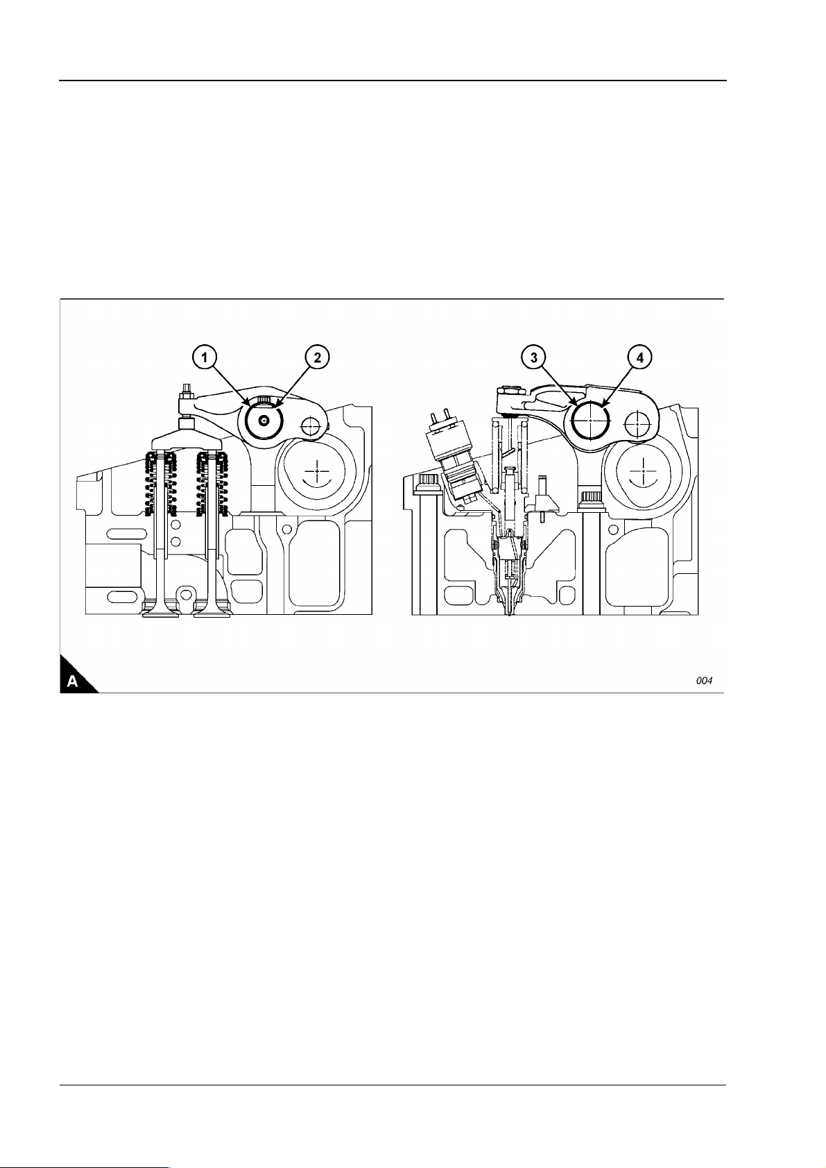
2 The valve rocker levers (A1) and the unit injector rocker levers (A2) can move on the shaft (A6) after the four
bolts (A5) have been removed. The shaft (A6) should be kept level when removed from the cylinder head. To
avoid possible personal injury, keep fingers clear of the rocker levers (A1 and A2) during removal of the
assembly from the cylinder head.
3 Remove the four bolts (A5). 4 Remove the shaft (A6), valve rocker levers (A1) and unit injector rocker levers (A2) as a unit. 5 Repeat steps 1 and 2 for the rocker shaft assemblies which remain.
To fit
1 Loosen the adjustment screws (A3 and A4) of each of the rocker levers which have been removed. Install
the rocker shaft assembly in the reverse order to removal.
2 Set the tappet clearances, Operation 3-4. 3 Check/adjust the unit injectors, Operation 3-13. 4 Fit the rocker cover, Operation 3-1.
Workshop Manual, TSD3455E, Issue 1 29
Page 40

3
This document has been printed from SPI². Not for Resale
To dismantle and to assemble Operation 3-3
To dismantle Note: Check the condition of all components and renew any which are worn or damaged. 1 Slide the valve rocker levers (A3) and the unit injector rocker levers (A4) from the shaft (A7).
Note: Fit a new ‘O’ ring seal to any rocker lever adjuster if its button (A1) has been removed from the
adjustment screw (A2).
2 Remove the button (A1) from the adjustment screw (A2) in the valve rocker lever (A3). 3 Remove the button (A6) from the adjustment screw (A5) in the unit injector rocker lever (A4). 4 Repeat steps 1 to 3 for the rocker lever assemblies which remain.
2300
30 Workshop Manual, TSD3455E, Issue 1
Page 41

2300
This document has been printed from SPI². Not for Resale
To assemble 1 Install new ‘O’ ring seals in the buttons (A1).
2 Install new ‘O’ ring seals in the buttons (A6). 3 To fit the ‘O’ ring seals and buttons to the valve rocker levers, proceed as follows: a. Support the valve rocker lever (A3) in a vice which has soft jaws.
b. Put the ‘O’ ring seal and button (A1) on the round end of the adjustment screw (A2). c. Use a soft hammer to seat the button on the adjustment screw. 4 To fit the ‘O’ ring seals and buttons to the unit injector rocker levers, proceed as follows:
a. Support the unit injector rocker lever (A4) in a vice which has soft jaws. b. Put the ‘O’ ring seal and button (A6) over the end of adjustment screw (A5). c. Use a soft hammer to seat the button on the adjustment screw. 5 Repeat steps 3 and 4 for the rocker levers which remain.
6 Fit the assembled rocker levers to the shafts (A7). Ensure that they are fitted to their original positions.
3
Workshop Manual, TSD3455E, Issue 1 31
Page 42

3
This document has been printed from SPI². Not for Resale
2300
How to check/adjust the tappet clearances Operation 3-4
Special requirements
Special tools Tappet clearances
Description Part number Inlet Exhaust
Engine turning tool CH11148 0,38 mm (0.015 in) 0,76 mm (0.030 in)
The tappet clearance is measured between the rocker levers and the top of the valve bridge pieces. The
operation must be done with the engine cold and stopped. Refer also to Operation 3-13, How to check/adjust
the electronic unit injectors.
1 Remove the rocker cover, Operation 3-1. 2 Remove the cover (A2) from the flywheel housing. The top bolt (A1) is the timing bolt.
Caution: If a customer-fitted speed sensor is fitted to the flywheel housing, it must be removed before the
engine turning tool can be inserted.
3 Remove the plug (A3) from the timing bolt location in the flywheel housing and fit the timing bolt.
Note: There are two locations for the timing bolt, one at each side of the flywheel housing. Use the location
that is the most convenient.
4 Insert the engine turning tool, CH11148, into the flywheel housing through the aperture behind the cover
(A2). Use a
rotation (anti-clockwise when viewed on the flywheel) until the timing bolt engages with the threaded hole in
the flywheel. The piston of number 1 cylinder is now at TDC (top dead centre).
Caution: If the flywheel is turned past the threaded hole, the flywheel must be turned in the opposite direction
for approximately 45 degrees and then back in the normal direction of rotation until the timing bolt engages
with the threaded hole. This is to eliminate backlash.
1
/2 inch drive ratchet with the turning tool to rotate the engine flywheel in the normal direction of
Continued
32 Workshop Manual, TSD3455E, Issue 1
Page 43

2300
This document has been printed from SPI². Not for Resale
5 Check the inlet and exhaust valves of the number 1 cylinder. If they are fully closed the piston is on its
compression stroke and the rocker levers can be moved by hand. If the rocker levers can not be moved
because the valves are slightly open, the piston is on its exhaust stroke. If it is on its exhaust stroke, withdraw
the timing bolt and turn the flywheel a further 360 degrees in the normal direction of rotation so that the number
1 cylinder is set to TDC on its compression stroke, then insert again the timing bolt.
6 Before each set of tappet clearances is adjusted, ensure that the roller of the rocker lever is fully against the
camshaft lobe.
7 Use a set of feeler gauges, inserted at the position shown (B3) between the valve bridge piece and the rocker
lever button, to check the tappet clearances for the inlet valves (C1) on cylinders 1, 2 and 4. Adjust the
clearances if necessary. Check the tappet clearance for the exhaust valves (C2) on cylinders 1, 3 and 5, and
adjust the clearances if necessary.
3
Continued
Workshop Manual, TSD3455E, Issue 1 33
Page 44

3
N
This document has been printed from SPI². Not for Resale
otes:
l Move each valve bridge piece before the feeler gauge is inserted to reduce the effect of the oil film.
l During the procedure, ensure that the feeler gauge is fully inserted
8 After each unit has been adjusted, tighten the lock nut (B2) of the adjustment screw (B1) to a torque of 30 +/
- 4 Nm (22 +/- 3 lbf ft).
9 Withdraw the timing bolt and rotate the flywheel by 360 degrees so that the number 6 piston is at TDC on
its compression stroke. Insert again the timing bolt into the threaded hole.
10 Check the tappet clearances for the inlet valves (C1) on cylinders 3, 5 and 6. Adjust the clearances if
necessary. Check the tappet clearances for the exhaust valves (C2) on cylinders 2, 4 and 6, and adjust the
clearances if necessary.
11 After each unit has been adjusted, tighten the lock nut of the adjustment screw to a torque of 30 +/- 4 Nm
(22 +/- 3 lbf ft).
12 Check again the tappet clearances for all six cylinders. 13 Fit the rocker cover. Remove the engine turning tool and the timing bolt and fit the cover to the flywheel
housing. Fit the plug to the timing bolt location.
2300
34 Workshop Manual, TSD3455E, Issue 1
Page 45

2300
This document has been printed from SPI². Not for Resale
3
Cylinder head assembly
To remove and to fit Operation 3-5
Special requirements
Special tools Consumable products
Description Part number Description Part number
Guide bolt, camshaft gear GE50019 Special lubricant CV60895
Socket, cylinder head bolt GE50020
Lifting bracket VP12712
To remove 1 Remove the thermostat housing, Operation 12-10.
2 Remove the exhaust manifold, Operation 9-1. 3 Remove the rocker lever and rocker shaft assemblies, Operation 3-2. 4 Remove the electronic unit inj ec tor s, Oper at ion 3-12. 5 Remove the gear case cover, Operation 6-1. 6 Disconnect the cable and remove the timing sensor from the cylinder head. 7 Remove the support bracket which is fitted between the gear case and the cylinder head. 8 Remove one bolt from the camshaft gear and install the guide stud, GE50019. Remove the five bolts which
remain and withdraw carefully the camshaft gear. Remove the guide stud.
9 Disconnect the fuel lines from the front and rear of the cylinder head. Fit temporary covers to the fuel lines
and also to the ports on the cylinder head.
10 Remove the cylinder head bolts; use the special socket, GE50020. 11 Fit the lifting bracket (A1), VP12712, to the cylinder head and attach a suitable hoist. Remove the cylinder
head. The cylinder head weighs approximately 148 kg (325 lb).
Retaining compound 21820 638
Continued
Workshop Manual, TSD3455E, Issue 1 35
Page 46

3
This document has been printed from SPI². Not for Resale
12 Remove the cylinder head gasket (B4). 13 Remove the ‘O’ ring seal from the oil transfer tube (B6) and remove the 24 coolant seals (B3). 14 Remove the seal (B2). 15 Remove the spacer plate (B5) and discard the spacer plate gasket. 16 Remove the second ‘O’ ring seal from the oil transfer tube (B6).
2300
36 Workshop Manual, TSD3455E, Issue 1
Page 47

2300
This document has been printed from SPI². Not for Resale
To fit
1 If the oil transfer tube (B6) has been removed, apply retaining compound, 21820 638, and insert it in the
crankcase. It must protrude from the top face of the crankcase by 20,0 +/- 0,5 mm (0.79 +/- 0.02 in). Remove
any excess compound and ensure that the bore of the oil transfer tube is clean.
2 If the rear dowel has been removed, apply retaining compound, 21820 638, and insert it in the crankcase.
It must protrude from the top face of the crankcase by 18,5 +/- 0,5 mm (0.73 +/- 0.02 in).
3 If the front dowel, close to the oil transfer tube, has been removed, it must be fitted in a dry condition. It must
protrude from the top face of the crankcase by 16,0 +/- 0,5 mm (0.63 +/- 0.02 in).
Note: Ensure that the spacer plate and the machined surface of the cylinder block are clean and free from dirt
and gasket material. Both surfaces of the spacer plate gasket and the top of the cylinder block must be clean.
Do NOT use a gasket adhesive on the surfaces.
4 Fit suitable guide studs (B1) to the cylinder block. Fit a new spacer plate gasket over the dowels in the
cylinder block.
Note: Apply a small amount of clean engine oil to the seals and ‘O’ ring seals before installation. 5 Fit a new ‘O’ ring seal to the oil transfer tube (B6).
6 Fit the spacer plate (B5) and fit the second ‘O’ ring seal to the oil transfer tube (B6). Fit the 24 coolant seals
(B3) and a new seal (B2) to the oil drain passage.
7 Check, and if necessary adjust, the protrusion of the cylinder liners, Operation 7-3. 8 Fit a new cylinder head gasket (B4) to the spacer plate.
3
Continued
Workshop Manual, TSD3455E, Issue 1 37
Page 48

3
This document has been printed from SPI². Not for Resale
9 Fasten a hoist to the cylinder head, use the lifting bracket VP12712, and lower the cylinder head onto the
spacer plate.
10 Apply special lubricant, CV60895, to the washers, the threads and under the heads of the bolts and fit the
cylinder head bolts and washers. The long bolts must be fitted at the positions shown in the black circles (C).
Use the special socket, GE50020, and the procedure which follows to tighten the bolts correctly:
a. Tighten the cylinder head bolts in the sequence given (C) to a torque of 270 +/- 15 Nm (200 +/- 11 lbf ft).
b. Tighten the cylinder head bolts in the sequence given (C) to a torque of 450 +/- 20 Nm (333 +/- 15 lbf ft).
c. Again, tighten the cylinder head bolts in the sequence given (C) to a torque of 450 +/- 20 Nm (333 +/-
15 lbf ft).
Caution: After the cylinder head assembly has been removed and fitted, it is necessary to check the backlash
between the camshaft and the idler gears. Incorrect adjustment can cause damage to components.
11 Fit the camshaft gear. Check and, if necessary, adjust the backlash between the camshaft gear and the
idler gear, Operation 3-11.
12 Fit the gear case cover, Operation 6-1. 13 Fit the support bracket between the cylinder head and the gear case. 14 Fit the electronic unit injectors, Operation 3-12. 15 Fit the rocker lever and shaft assemblies, Operation 3-2. 16 Fit the exhaust manifold, Operation 9-1. 17 Fit the thermostat housing, Operation 12-10. 18 Remove the covers from the fuel lines and from the fuel line ports on the cylinder head. Connect the fuel
lines to the cylinder head and attach any relevant clamps. 19 Fit the timing sensor and connect the cable.
2300
38 Workshop Manual, TSD3455E, Issue 1
Page 49

2300
This document has been printed from SPI². Not for Resale
3
Valve springs
To remove and to fit Operation 3-6
Special requirements
Special tools
Description Part number
Valve spring compressor GE50026
To remove
Note: The valve springs can be removed with the cylinder head either fitted to or removed from the engine.
The procedure given here is for use when the cylinder head is fitted to the engine. Before any components are
removed, ensure that the relevant piston is set to the top of its compression stroke. If the piston is not at this
position, the valves can fall into the cylinder liner.
Caution: If a valve falls into the cylinder liner, the cylinder head must be removed.
1 Remove the rocker lever and rocker shaft assemblies, Operation 3-2. 2 Remove the electronic unit inj ec tor s, Oper at ion 3-12. 3 Set the piston for the relevant valve spring assembly to the top of its compression stroke. 4 Use the hold- down clam p from the el ectroni c unit inj ector to secu re the valv e spring co mpressor, GE50026,
to the cylinder head.
5 Insert the stud and base of the valve spring compressor into the bore of the injector sleeve. Use the bolt and
clamp from the electronic unit injector to secure the stud and base to the cylinder head. Fit the compressor
plate (A1) over the stud and fit the thrust bearing, the washer and the nut (A2)
6 Tighten the nut until the collets are loose on the valves. 7 Remove two collets from each valve. 8 Loosen slowly, then remove the nut, washer, thrust bearing and plate. 9 Remove the rotocoils, valve springs and washers from each valve. 10 Inspect the valve springs, refer to Chapter 2, Specifications for the correct dimensions and spring force. 11 Repeat steps 3 to 10 for the other valve spring assemblies which are to be removed.
Workshop Manual, TSD3455E, Issue 1 39
Page 50

3
This document has been printed from SPI². Not for Resale
To fit 1 Apply clean engine oil to the relevant valve stems.
2 Fit the washer, valve spring and rotocoil to each valve. 3 Use the valve spring compressor, GE50026, to compress the valve springs. Note: The collets are tapered. When fitted, the large (thick) diameter must be uppermost.
4 Fit two collets to each valve.
Caution: The collets can be dislodged from the valve stem during the removal of the valve spring compressor.
Ensure that the collets are seated correctly during this procedure.
5 Loosen slowly and then remove the nut (A2) and plate (A1) of the valve spring compressor. Remove the
other parts of the valve spring compressor tool and ensure that the collets are fitted correctly to the valve
stems.
6 Tap lightly each valve with a soft hammer to ensure that the collets are seated correctly. 7 Fit the electronic unit injectors, Operation 3-12. 8 Fit the rocker lever and rocker shaft assemblies, Operation 3-2.
2300
40 Workshop Manual, TSD3455E, Issue 1
Page 51

2300
This document has been printed from SPI². Not for Resale
3
Valves
To remove and to fit Operation 3-7
Special requirements
Special tools
Description Part number
Valve spring compressor GE50026
To remove 1 Remove the cylinder head, Operation 3-5.
Note: If more than one valve is to be removed, make a note of the position of the valves as they are removed
from the cylinder head.
2 Put the cylinder head, flame face down, on a bench with a soft surface and release the valves by use of the
valve spring compressor, GE50026. Use the procedure given in Operation 3-6.
3 Withdraw the valves from the cylinder head. 4 Repeat the procedure for all valves which are to be removed.
To fit
1 Apply clean engine oil to the stems of the valves. Fit the valves to their original positions in the cylinder head.
2 Use the special tool, GE50026, and the procedure given in Operation 3-6, to install the valve springs. 3 Fit the cylinder head, Operation 3-5.
Workshop Manual, TSD3455E, Issue 1 41
Page 52

3
This document has been printed from SPI². Not for Resale
2300
Valve seals
To renew Operation 3-8
Special requirements
Special tools
Description Part number
Insertion tool, valve seal GE50027
Note: The valve seals can be removed with the cylinder head either fitted to or removed from the engine. 1 Remove the relevant valve spring assembly, Operation 3-6.
2 Remove the valve seal from the valve and valve guide. 3 Apply a thin film of clean engine oil to the new valve seal and slide the seal over the valve stem. 4 If the valve seal is to be fitted to a valve guide with the valve removed, fit the seal to the special tool,
GE50027. Insert the seal pin (part of the special tool GE50027) through the insertion tool, then enter the seal
pin into the bore of the valve guide.
5 Use the special tool, GE50027, and hand pressure only to push the valve seal into its position in the valve
guide.
6 Withdraw the tool and fit the valve spring assembly, Operation 3-6.
42 Workshop Manual, TSD3455E, Issue 1
Page 53

2300
This document has been printed from SPI². Not for Resale
3
Valve guides
To remove and to fit Operation 3-9
Special requirements
Special tools
Description Part number
Removal/installation tool GE50043
Sleeve GE50044
To remove 1 Remove the cylinder head, Operation 3-5.
2 Remove the valves, Operat ion 3-7. 3 Use the special tool (A1), GE50043, and a hammer to drive the valve guide (A2) from the cylinder head.
Workshop Manual, TSD3455E, Issue 1 43
Page 54

3
This document has been printed from SPI². Not for Resale
To fit 1 Apply clean engine oil to the outside diameter of the new valve guides.
2 Use the special tool (B1), GE50043, together with the sleeve (B2), GE50044, to install the valve guide. The
guide must protrude from the cylinder head, as shown (C1), by 35,0 +/- 0,5 mm (1.38 +/- 0.02 in).
Refer to Chapter 2, Specifications for the correct dimensions for the inside diameter of new and used valve
guides.
3 When a new valve guide has been fitted, check that there is full contact between the valve and the valve
seat. If necessary, lap the valve to the seat.
4 Fit the valves, Operation 3-7. 5 Fit the cylinder head, Operation 3-5.
2300
44 Workshop Manual, TSD3455E, Issue 1
Page 55

2300
This document has been printed from SPI². Not for Resale
3
Camshaft
To remove and to fit Operation 3-10
Special requirements
Special tools Consumable products
Description Part number Description Part number
Engine turning tool CH11148 Thread lock compound (10 ml) 21820 117
Guide stud GE50019
Cradle tool GE50018
Camshaft guide GE50017
Pilot GE50015
Lifting hooks GE50025
Alignment sleeve GE50016
To remove 1 Remove the radiator, Opera tio n 12 -4.
2 Remove the fan, Operation 12-5. 3 Remove the gear case cover, Operation 6-1. 4 Remove the rocker cover, Operation 3-1. 5 Remove the rocker lever and shaft assemblies, Operation 3-2. 6 Remove the cover (A2) from the flywheel housing. The top bolt (A1) is the timing bolt. 7 Remove the plug (A3) from the timing bolt location in the flywheel housing and fit the timing bolt. Note: There are two locations for the timing bolt, one at each side of the flywheel housing. Use the location
which is the most convenient.
Continued
Workshop Manual, TSD3455E, Issue 1 45
Page 56

3
C
This document has been printed from SPI². Not for Resale
2300
8 Insert the engine turning tool, CH11148, into the flywheel housing through the aperture behind the cover
(A2). Use a
rotation (anti-clockwise when viewed on the flywheel) until the timing bolt engages with the threaded hole in
the flywheel. The piston of number 1 cylinder is now at TDC (top dead centre). When the number one piston
is at top dead centre on its compression stroke, the mark on the camshaft gear is be aligned with the mark on
the gear case. If the mark is not aligned, withdraw the timing bolt, rotate the crankshaft a further 360 degrees
in the normal direction of rotation and insert the timing bolt again.
autions:
l If the flywheel is turned past the threaded hole, the flywheel must be turned in the opposite direction for
approximately 45 degrees and then back in the normal direction of rotation until the timing bolt engages
with the threaded hole. This is to eliminate backlash.
l Do not rotate the crankshaft with the camshaft gear or any of the idler gears removed and the rocker shaft
assemblies installed. Damage can be caused to the pistons and valves, or to both.
9 Disconnect the lead and remove camshaft timing sensor from behind the top of the gear case. 10 Remove one bolt from the camshaft gear and install the guide stud, GE50019. Remove the five bolts which
remain.
11 Attach a hoist to the camshaft gear and withdraw the gear from the camshaft. Remove the guide stud. 12 Remove three bolts and withdraw the thrust plate, the adaptor plate and the seal assembly. Note: Take care during removal of the camshaft to ensure that the surfaces of both the camshaft and the
camshaft bearings are not damaged. Use the procedure which follows, together with the relevant special tools,
to avoid damage to the engine and components.
13 Use the bolts of the rocker shaft to retain the cradle tool (B1), GE50018, at the position shown (B).
1
/2 inch drive ratchet with the turning tool to rotate the engine flywheel in the normal direction of
Continued
46 Workshop Manual, TSD3455E, Issue 1
Page 57

2300
This document has been printed from SPI². Not for Resale
14 Remove the rear cover (C1), complete with seal (C3). 15 Fit the camshaft guide (D1), GE50017, to the gear case. Do not tighten the bolts for the guide at this stage. Note: It is necessary to install two pilots, GE50015, on the rear end of the camshaft. The second pilot will
support the rear of the camshaft as it is moved from the cylinder head and into the guide, GE50017.
16 Install a pilot tool, GE50015, into the threaded hole at the rear end of the camshaft. Then attach the second
pilot tool, GE50015, to the first.
17 Withdraw the camshaft until it enters the bore of the camshaft guide. Tighten the bolts which retain the
guide on the gear case. 18 Use the lifting hooks, GE50025, to move the camshaft toward the front of the engine.
Caution: During use of the lifting hooks do not raise the camshaft; the camshaft should be supported by the
cradle, GE50018. If the camshaft is raised, damage to the camshaft bearings can occur.
19 Withdraw the camshaft from the cylinder head just enough for a strap and hoist to be attached. Attach a
suitable strap and hoist to support the camshaft, ensure that the camshaft is kept level and withdraw it from
the cylinder head. The camshaft weighs approximately 39 kg (85 lb).
3
Workshop Manual, TSD3455E, Issue 1 47
Page 58

3
This document has been printed from SPI². Not for Resale
To fit
1 Fit the two pilot tools, GE50015, to the rear end of the camshaft. Ensure that the camshaft and camshaft
bearings have been cleaned thoroughly. Apply clean engine oil to the lobes and journals of the camshaft. Apply
a thin coat of clean engine oil to the camshaft bearings.
2 Fit the camshaft guide (E1), GE50017, to the gear case cover, but do not tighten the bolts fully. 3 Insert the alignment sleeve (E2), GE50016, through the camshaft guide (E1) and into the camshaft bearings
to align the camshaft guide correctly. Tighten the bolts which retain the camshaft guide, GE50017, on the gear
case. Remove the alignment sleeve; the sleeve should move freely from the bore of the camshaft guide,
GE50017.
4 Fit the cradle tool (F1), GE50018, at the position shown (F). Note: Rotate the camshaft in both directions during installation to prevent binding.
5 Use a suitable strap and hoist to support the camshaft. Insert the camshaft through the guide and into the
cylinder head. Move the camshaft into the head as far as the strap and hoist will allow.
6 Remove the strap and hoist. Rotate the camshaft during installation. Do not allow the end of the camshaft
to drop during removal of the hoist as the bearings can be damaged. Use the lifting hooks, GE50025, to
support the camshaft during installation.
7 Remove the pilot tools and push the camshaft fully into its bore. 8 Inspect the seal (G3) and renew if necessary. Fit the rear cover (G1), complete with seal (G3).
2300
Continued
48 Workshop Manual, TSD3455E, Issue 1
Page 59

2300
This document has been printed from SPI². Not for Resale
9 Remove the cradle tool and the camshaft guide. 10 Fit new ‘O’ ring seals to the camshaft front seal plate. Apply a small amount of engine lubricating oil to the
‘O’ ring seal on the outside of the plate. Fit the seal plate with the face seal against the cylinder head. Insert
the adapter plate and fit the thrust plate. Apply thread lock compound, 21820 117, to the three bolts, fit the
bolts and tighten.
Note: Camshaft timing is very important. During installation of the camshaft assembly, ensure that the timing
marks on the camshaft gear and the gear case cover are aligned when number one cylinder is at top centre
(TDC).
11 Fit the guide stud, GE50019, to the camshaft. 12 Fit the camshaft gear; align the hole in the gear with the dowel pin on the adapter plate. If the timing mark
on gear does not align with the pointer at the top of the gear case, remove the gear and rotate the camshaft
until the gear can be installed with the marks aligned.
13 Fit the bolts which retain the gear, remove the guide stud and fit the bolt which remains. Tighten the bolts
to a torque of 240 +/- 40 Nm (177 +/- 30 lbf ft).
14 Fit the camshaft timing sensor to its location behind the top of the gear case and connect the lead. 15 Fit the gear case cover, Operation 6-1. 16 Remove the timing bolt from the flywheel and fit the cover and plug. 17 Install the rocker lever and shaft assemblies, Operation 3-2.
3
Workshop Manual, TSD3455E, Issue 1 49
Page 60

3
This document has been printed from SPI². Not for Resale
2300
How to set the backlash for the camshaft gear Operation 3-11
If the cylinder head or the camshaft is removed, the backlash between the camshaft gear (A1) and the
adjustable idler gear (A2) must be checked and, if necessary, adjusted. The backlash between the camshaft
gear and the adjustable idler gear, and also between the adjustable idler gear (A2) and the main idler gear
(A3), must be 0,25 +/- 0,08 mm (0.010 +/- 0.003 in).
Note: This procedure must be performed before the rocker lever and shaft assemblies are fitted.
1 Remove the main idler gear (A3). Hold the camshaft gear stationary and use a dial test indicator (DTI),
mounted on the gear case, to check the backlash of the adjustable idler gear.
2 Fit the main idler gear (A3), hold the main idler gear stationary and measure the backlash on the adjustable
idler gear.
3 To adjust the backlash, remove the three bolts and thrust plate which retain the adjustable idler gear (A2)
and remove the gear. Loosen the five nuts (B3) and the bolt (B1) which retain the stub axle (B2) and move the
stub axle by the relevant amount. Tighten the nuts and bolt to a torque of 47 +/- 9 Nm (35 +/- 7 lbf ft).
4 Fit the idler gear. Retain with the thrust plate and three bolts. Check again the backlash between the
adjustable idler gear and the camshaft gear, and also between the adjustable idler gear (A2) and the main idler
gear (A3), as given in steps 1 and 2. Repeat the procedure if necessary until the correct backlash settings have
been obtained.
5 When the correct backlash settings have been obtained, remove the adjustable idler gear and proceed as
follows: Remove one of the nuts which retains the idler axle, apply a small amount of Loctite 542 to the threads
of the stud, fit the nut and tighten to a torque of 47 +/- 9 Nm (35 +/- 7 lbf ft). Repeat this procedure for the other
four nuts and the bolt; work on one nut or bolt at a time so that the position of the stub axle is not affected.
50 Workshop Manual, TSD3455E, Issue 1
Page 61

2300
This document has been printed from SPI². Not for Resale
3
Electronic injector units
To remove and to fit Operation 3-12
Special requirements
Special tools
Description Part number Description Part number
Injector installer/removal GE50021 Brush GE50022
Vacuum pump GE50028 Brush GE50023
Tube GE50030
Bottle GE50029
To remove
Warning! The electrical circuit for the fuel injector units operates on 110 volts. Do NOT work on the fuel injector
units unless the power supply to the ECM has been disconnected.
1 Remove the relevant rocker shaft assembly, Operation 3-2. 2 Loosen the two nuts and remove the electrical connector from the injector unit. 3 Mark the valve bridge pieces to assist during assembly, then remove them. 4 Remove the bolt (A2) from the spacer and clamp which retain the injector unit and use the special tool,
GE50021, to release the injector unit from the cylinder head.
Caution: If more than one injector unit is to be removed, make a note of the trim code (A1), a four-digit number
adjacent to the bar code, and also the cylinder to which the unit is fitted.
Brush GE50024
5 Remove the injector unit, together with the spacer and clamp. 6 Use the vacuum pump, GE50028, together with the tube, GE50030, and bottle, GE50029, to extract any
fuel which has spilled into the combustion chamber during removal of the injector.
Workshop Manual, TSD3455E, Issue 1 51
Page 62

3
This document has been printed from SPI². Not for Resale
To fit
1 Clean thoroughly the bore of the injector sleeve and cylinder head. Use the special brushes (GE50022,
GE50023 and GE50024) to remove carbon or dirt.
2 Check the condition of the ‘O’ ring seals (B1 and B2); renew the seals if they are worn or damaged. Lubricate
the ‘O’ ring seals with clean engine oil before the injector unit is installed in the cylinder head.
Caution: Injector units MUST be fitted to their original positions or the information in the ECM will need to be
updated.
3 Fit the injector unit to the cylinder head. Fit the clamp, spacer and retaining bolt. Tighten the bolt (A2) to a
torque of 47 +/- 9 Nm (35 +/- 7 lbf ft).
4 Fit the bridge pieces. 5 Attach the electrical connector to the injector unit and retain with the two nuts. Tighten the nuts to a torque
of 2,5 Nm (22 lbf in). 6 Fit the rocker shaft assembly, Operation 3-2.
2300
52 Workshop Manual, TSD3455E, Issue 1
Page 63

2300
This document has been printed from SPI². Not for Resale
3
To check and to adjust Operation 3-13
Special requirements
Special tools
Description Part number
Injector height gauge CH11149
This operation should be performed at the same time as the operation to check the valve tappet clearances.
Warning! The electrical circuit for the fuel injector units operates on 110 volts. Do NOT work on the fuel injector
units unless the power supply to the ECM has been disconnected.
1 With the rocker covers removed, set the number 1 piston to TDC (top dead centre) on its compression
stroke. Check/adjust the height dimensions for the fuel injectors of cylinders 3, 5 and 6.
2 Use the fuel injector setting gauge, CH11149, to obtain the correct height for the fuel injector. The dimension
to be measured is from the top of the unit injector (A1) to the machined ledge on the fuel injector body (A2).
This dimension should be 78,0 +/- 0,2 mm (3.07 +/- 0.01 in). Slacken the lock nut and use the adjustment screw
of the rocker lever to obtain the correct dimension. Tighten the lock nut to a torque of 55 +/- 10 Nm (41 +/7lbfft).
3 Remove the timing bolt from the flywheel housing and rotate the flywheel by 360 degrees in the normal
direction of engine rotation until the timing bolt can be inserted into the threaded hole. This will put the number
1 piston at TDC in its exhaust stroke.
4 Check/adjust the height dimensions for the fuel injectors of cylinders 1, 2 and 4 as given in step 2.
When all adjustments have been made, remove the timing bolt, fit the cover to the flywheel housing, fit the plug
to the timing bolt position and fit the rocker covers.
Workshop Manual, TSD3455E, Issue 1 53
Page 64

3
This document has been printed from SPI². Not for Resale
2300
Injector sleeves
To remove and to fit Operation 3-14
Special requirements
Special tools
Description Part number Description Part number
Injector installer/removal GE50021 Brush GE50022
Vacuum pump GE50028 Brush GE50023
Tube GE50030
Bottle GE50029
To remove 1 Remove the rocker shaft assemblies, Operation 3-2.
2 Remove the electronic injector units, Operation 3-12. 3 Mark the bridge pieces and make a note of their position to assist during assembly, then remove the bridge
pieces.
4 Fit the puller stud from the special tool, GE50021, into the injector sleeve as shown (A). Fit the bridge, thrust
bearing, washer and nut, from the special tool, over the stud as shown. Tighten the nut (A1) of the special tool
until the sleeve is drawn from the cylinder head. Remove the special tool from the sleeve.
5 Remove the ‘O’ ring seals from the injector sleeve. Check the condition of the injector sleeve and renew if
necessary.
6 Repeat steps 1 to 5 for the injector sleeves which remain.
Brush GE50024
54 Workshop Manual, TSD3455E, Issue 1
Page 65

2300
This document has been printed from SPI². Not for Resale
To fit
Caution: Before installation ensure that the injector sleeve and its bore in the cylinder head are clean and free
from oil, dirt and sealant.
1 Use the brushes, special tool numbers: GE50023, GE50024 and GE50022, to clean thoroughly the bore for
the injector sleeve.
Caution: Ensure that the fuel passage in the cylinder head is clean.
2 Fit new ‘O’ ring seals to the injector sleeve. 3 Fit the stud from the special tool into the threads of the injector sleeve.
Caution: Do not apply retaining and anti-seize compounds to the cylinder head surfaces. These compounds
must ONLY be applied to the injector sleeve.
4 Apply CV60889 anti-seize compound to the ‘O’ ring seals and to the large diameter (B1) off the injector
sleeve.
5 Apply CV60893 retaining compound to the small diameter (B2) off the injector sleeve. 6 Using the stud, insert the injector sleeve into its bore in the cylinder head. Take care to prevent damage to
the ‘O’ ring seals. Use that only hand force is used to push the injector sleeve into the cylinder head.
7 Fit the driver tool over the stud and tap lightly with a hammer to ensure that the injector sleeve is fully seated
in the cylinder head. The tool and sleeve will "ring" when the sleeve is in full contact with the base of the bore.
8 Use a clean cloth to remove any retaining or anti-seize compound from the bores of the cylinder and injector
sleeve.
9 Fit the electronic injector units, Operation 3-12. 10 Fit the rocker shaft assemblies, Operation 3-2.
3
Workshop Manual, TSD3455E, Issue 1 55
Page 66

This page is intentionally blank
This document has been printed from SPI². Not for Resale
Page 67

2300
This document has been printed from SPI². Not for Resale
4
Pistons and connecting rod assemblies 4
General information
The pistons fitted to the 2300 and 2800 Series engines consist of two parts: a forged steel crown (A1) and a
cast aluminium skirt (A2). The two parts are retained on the connecting rod by the gudgeon pin (A4). The
pistons each have three rings fitted to grooves in the crown. The top ring is keystone shaped and its face is
plasma coated. The second ring has a tapered face which has a chrome finish. The third ring is an oil control
ring and also has a chrome finish on its face. The oil control ring contains a coil spring which expands the ring.
Small holes in the piston groove allow oil from the oil control ring to drain back to the sump.
The connecting rods are of a conventional design. The small end is wedge shaped and the big end bearing
cap is retained by two special bolts. A split type shell bearing is fitted at the big end and a single piece bearing
is pressed into the small end.
Piston squirter jets provide a supply of oil to cool the piston crown. On 2806 engines, an oil cooling chamber
is formed by the lip at the top of the piston skirt and the cavity behind the ring grooves in the piston crown. The
oil returns to the sump through the clearance gap between the crown and the skirt. For pistons fitted to the
2306 engine, the oil cooling chamber is formed between the cavity behind the ring grooves and two flat plates
fitted in the piston crown. There is a hole in each plate; the oil supply is squirted through one hole, flows around
the cooling chamber and returns to the sump through the hole at the opposite side.
Workshop Manual, TSD3455E, Issue 1 57
Page 68

4
This document has been printed from SPI². Not for Resale
2300
Pistons and connecting rod assemblies
To remove and to fit Operation 4-1
Special requirements
Special tools Consumable products
Description Part number Description Part number
Installer, piston (2806 engine) GE50003
Installer, piston (2306 engine) GE50045
To remove 1 Remove the cylinder head assembly, Operation 3-5.
2 Remove the oil pump, Operation 10-4. 3 Remove the stiffener plate from the base of the crankcase. 4 Remove the carbon ridge from the top inside surface of the cylinder liners. 5 Turn the crankshaft until two pistons are at bottom centre. 6 Remove the bolts (A1) and the bearing caps. Push the connecting rods and pistons up until the rings are
free from the cylinder liners.
7 Withdraw carefully the pistons and connecting rods from the cylinder liners. Store the bearing caps with their
relevant connecting rods. 8 Repeat steps 3 to 6 for the remainder of the pistons and connecting rods.
Anti-seize compound CV60890
58 Workshop Manual, TSD3455E, Issue 1
Page 69

2300
This document has been printed from SPI². Not for Resale
To fit 1 Apply clean engine oil to the piston rings, the connecting rod bearings and the cylinder liners.
2 Ensure that the piston ring gaps are set at 120 degree intervals to each other. 3 Use the special tool (B1), GE50003 for 2806 engines or GE50045 for 2306 engines, to install the piston and
the connecting rod in the cylinder liner (B2). The connecting rod must be fitted with tab groove side of the big
end bearing at the opposite side to the camshaft. Proceed with care to ensure that the piston rings are not
damaged during the operation.
Caution: Bearing caps must be fitted to their original connecting rods,
4 Fit the bearing cap to the connecting rod. The cap must be fitted with its number on the same side as that
on the connecting rod and the number must be the same.
5 Apply anti-seize compound, CV60890, to the bolt threads. Install the bolts and bearing cap. Tighten each
bolt in the bearing cap to a torque of 90 +/- 8 Nm (66 +/- 6 lbf ft). Make a temporary mark on each bolt and the
bearing cap, then tighten each bolt by an additional 90 +/- 5 degrees.
6 Repeat steps 1 to 4 for the remainder of the pistons and connecting rods. 7 Fit the stiffener plate to the base of the crankcase. 8 Fit the oil pump, Operation 10-4. 9 Fit the cylinder head assembly, Operation 3-5.
4
Workshop Manual, TSD3455E, Issue 1 59
Page 70

4
This document has been printed from SPI². Not for Resale
2300
To dismantle and assemble Operation 4-2
To dismantle 1 Remove the pistons and connecting rod assemblies, Operation 4-1.
2 Remove the big-end bearing shells (A5) from the connecting rod (A4) and connecting rod cap. If the bearings
are to be used again, make a note of the position where they were fitted.
3 Remove the circlips (A1). 4 Remove the gudgeon pin (A2) and separate the connecting rod and the piston crown from the piston. 5 Remove carefully the piston rings (A3) from the piston crown and clean the piston ring grooves with a
suitable cleaning tool.
Special equipment is required to renew the small end bearing. If this operation becomes necessary, contact
your Perkins dealer .
60 Workshop Manual, TSD3455E, Issue 1
Page 71

2300
This document has been printed from SPI². Not for Resale
To assemble
1 Check the gaps between the ends of the piston rings when the rings are inserted in a new liner. The rings
can also be checked by insertion in an unworn part of a used liner.
For the correct dimensions refer to Chapter 2, Specifications.
2 Fit the spring of the oil control ring to its groove in the piston crown. Note: The oil control ring must be fitted over the spring with the gap of the oil control ring at 180 degrees from
the joint of the spring.
3 Use a suitable piston ring expander to fit the oil control ring to its groove in the piston crown. 4 Fit the second (intermediate) piston ring with the side that has the identification "UP-2" toward the top of the
piston. Use a suitable piston ring expander.
5 Fit the first (top) piston ring with the side that has the identification "UP-1" toward the top of the piston. Use
a suitable piston ring expander.
6 When all three piston rings have been fitted, adjust the position of the piston ring gaps so that they are
120 degrees apart.
7 Fit the piston crown into the piston skirt and insert the connecting rod. Apply clean engine oil to the gudgeon
pin (A2) and install the pin. Fit the circlips (A1). Ensure that the circlips are located fully in the grooves of the
piston.
8 Fit the big-end bearings to the connecting rod (A4) and connecting rod cap. If the original bearings are to be
used, ensure that they are fitted to their original positions.
Note: The tabs at back of the bearings must be located correctly in the tab slots of the connecting rod and
connecting rod cap.
4
9 Fit the pistons and connecting rod assemblies, Operation 4-1.
Workshop Manual, TSD3455E, Issue 1 61
Page 72

4
This document has been printed from SPI². Not for Resale
2300
Piston cooling jets
To remove and to fit Operation 4-3
Special requirements
Special tools
Description Part number
Engine turning tool CH11148
Jet alignment tool GE50004
To remove 1 Remove oil pump, Operation 10-4.
2 Use the engine turning tool, CH11148, to turn the crankshaft in a clockwise direction (as seen from the front
of the engine) to obtain access to the relevant piston cooling jet.
3 Remove the bolt which retains the cooling jet and remove the cooling jet from the engine. 4 Repeat steps 2 and 3 for the cooling jets which remain.
To fit
1 Before a piston cooling jet is fitted to the engine, use the jet alignment tool, GE50004, to ensure that the
direction of the nozzles is correct.
Caution: If, when fitted to the alignment tool, a nozzle does not align correctly with the relevant dowel, discard
the cooling jet; do NOT fit a damaged or distorted cooling jet to the engine.
2 Carefully fit the piston cooling jets to the engine, ensure that the nozzles of the cooling jets are not damaged
or distorted during the operation. Turn the crankshaft clockwise (as seen from the front of the engine) as
necessary to obtain access to the relevant positions.
3 Fit the oil pump, Operation 10-4.
62 Workshop Manual, TSD3455E, Issue 1
Page 73

2300
This document has been printed from SPI². Not for Resale
5
Crankshaft assembly 5
General information
The crankshaft fitted to the 2300 and 2800 Series engines has 13 bearing surfaces, which consists of seven
main journals and six crank pins. Each crank pin holds two connecting rods.
Eight counterweights are included within the crankshaft forging and a vibration damper is fitted at the front end
to reduce torsional vibrations.
A gear at the front end of the crankshaft provides the drive for the engine timing gears, the coolant pump and
the lubricating oil pump.
To seal the crankcase, crankshaft seals are fitted in the gear case and the flywheel housing.
Workshop Manual, TSD3455E, Issue 1 63
Page 74

5
This document has been printed from SPI². Not for Resale
2300
Crankshaft
To remove and to fit Operation 5-1
Special requirements
Consumable products
Description Part number
Anti-seize compound CV60890
To remove 1 Remove the gear case cover, Operation 6-1.
2 Remove the flywheel housing, Operation 13-2. 3 Remove the pistons and connecting rod assemblies, Operation 4-1. 4 Remove the crankshaft rear seal and wear sleeve, Operation 5-3. 5 Remove the crankshaft front seal and wear sleeve, Operation 5-2. Note: Make a note of the number on the bearing caps for assembly purposes. If a number cannot be seen, put
a number on the left side of the crankcase with a corresponding number on the bearing cap.
6 Remove the bolts (A1) which retain the main bearing caps in the crankcase and remove the bearing caps.
7 Fit one of the bolts from the front pulley to each end of the crankshaft. Fasten a hoist to the crankshaft and
lift the crankshaft from the crankcase. The weight of the crankshaft is approximately 159 kg (350 lb).
Note: If new main bearings are not to be installed, make a note of the position of the used bearings. Used
bearings must be fitted to their original positions.
64 Workshop Manual, TSD3455E, Issue 1
Page 75

2300
This document has been printed from SPI². Not for Resale
To fit
1 Clean the crankcase and the main bearing caps thoroughly. Apply clean engine oil to the main bearings and
fit the upper halves of the main bearings into the crankcase.
2 Install one of the bolts from the front pulley in each end of the crankshaft, fasten a suitable hoist and fit the
crankshaft into the crankcase. Ensure that the line mark on the crankshaft gear is in alignment with the line on
the idler gear.
3 Fit the thrust bearings for the centre main bearing. Ensure that the bearings are fitted with the side
identification "BLOCK SIDE" against the crankcase.
4 Fit the main bearings to the bearing caps. 5 Ensure that the tabs on the back of the bearing shells fit into the tab slots of the bearing caps and crankcase.
Caution: Ensure that the main bearing caps are fitted to the correct positions. The numbers on the side of the
crankcase must be the same as the numbers on the bearing caps, and the arrows on the bearing caps must
be directed toward the front of the crankcase.
6 Apply anti-seize compound, CV60890, to the bolts and install the main bearing caps and bolts. 7 Begin at the tab end of the bearing cap first, tighten each bearing cap bolt to a torque of 260 +/- 14 Nm
(190 +/- 10 lbf ft). Make a temporary mark on each bolt and bearing cap. Start with the bolt opposite the tab
end of the bearing cap and again tighten each bolt by an additional 120 +/- 5 degrees.
8 Use a dial test indicator (DTI) to check the end-float of the crankshaft. Ensure that the pointer of the DTI is
against a machined surface. The end-float is controlled by the thrust bearings of the centre main bearing. The
end-float with new bearings must be between 0,15 and 0,51 mm (0.006 and 0.020 in). The maximum
permissible end-float with used bearings is 0,89 mm (0.035 in).
9 Fit the crankshaft front seal and wear sleeve, Operation 5-2. 10 Fit the crankshaft rear seal and wear sleeve, Operation 5-3. 11 Fit the pistons and connecting rod assemblies, Operation 4-1. 12 Fit the flywheel housing, Operation 13-2. 13 Fit the gear case cover, Operation 6-1.
5
Workshop Manual, TSD3455E, Issue 1 65
Page 76

5
This document has been printed from SPI². Not for Resale
2300
Crankshaft front seal and wear sleeve
To renew Operation 5-2
Special requirements
Special tools Consumable products
Description Part number Description Part number
Locator assembly GE50008
Quick cure primer CV60892Bolt GE50009
Distorter protection ring GE50010
Distorter tool GE50011
Retaining compound CV60893Installer GE50012
Nut GE50014
To remove 1 Remove the vibration damper, Operation 5-4.
Note: The crankshaft front seal and wear sleeve are supplied as a set and must be installed as a set. If a seal
is renewed, the wear sleeve must also be renewed.
2 Drill three holes (A2) at an equal distance around the circumference of the seal. Fit self-tapping screws (A1),
complete with washers if necessary, to the holes and use a screwdriver as a lever to remove the seal from the
crankcase. Ensure that the gear case does not become damaged during this operation.
3 Fit the distorter protection ring (B1), GE50010, to the seal bore and at the same depth as the wear sleeve.
The distorter ring is fitted to protect the seal bore in the crankcase during the removal of the wear sleeve.
4 Insert the distorter tool (B2), GE50011, between the protection ring and the wear sleeve. With the sharp
edge of the tool against the wear sleeve, use a socket and spanner to rotate the distorter and cause a crease
to form in the wear sleeve. Repeat this procedure in three or more places until the wear sleeve becomes loose
on the crankshaft.
5 Remove the distorter tool, the protection ring and the wear sleeve.
66 Workshop Manual, TSD3455E, Issue 1
Page 77

2300
N
This document has been printed from SPI². Not for Resale
To fit
Note: Before th e new seal and wear slee ve are installe d, read carefully t he special instruc tion which is suppl ied
with each seal and wear sleeve.
1 Clean and the wear sleeve inside diameter and crankshaft outside diameter with quick cure primer,
CV60892. Apply some retaining compound, CV60893, to the crankshaft outside diameter before the wear
sleeve is installed on the crankshaft. Do not allow any quick cure primer or retaining compound to touch the
lip of the seal.
2 Use the bolts (C3), GE50009, to install the guide, GE50008, on the crankshaft.
otes:
l The seal and the wear sleeve must be installed in a dry condition.
l Ensure that the seal is fitted with the part number and the crankshaft rotation arrows toward the outside.
Caution: The front and rear seals and wear sleeves have different spiral grooves. The seal will not function if
it is installed at the wrong end of the engine.
3 Fit the wear sleeve and seal (C4) as a unit onto the locator, GE50008. 4 Fit the installer (C2), GE50012, onto the locator. 5 Apply clean engine oil to the face of the nut (C1), GE50014, and to its contact area on the installer, GE50012. 6 Fit the nut to the locator and tighten the nut until the inside surface of the installer is in contact with the
locator.
7 Remove all of the tools from the crankshaft. 8 Fit the vibration damper, Operation 5-4.
5
Workshop Manual, TSD3455E, Issue 1 67
Page 78

5
This document has been printed from SPI². Not for Resale
2300
Crankshaft rear seal and wear sleeve
To renew Operation 5-3
Special requirements
Special tools Consumable products
Description Part number Description Part number
Locator assembly GE50008
Quick cure primer CV60892Bolt GE50009
Distorter protection ring GE50010
Distorter tool GE50011
Retaining compound CV60893Installer GE50013
Nut GE50014
To remove 1 Remove the flywheel, Operation 13-1.
Note: The crankshaft front seal and wear sleeve are supplied as a set and must be installed as a set. If a seal
is renewed, the wear sleeve must also be renewed.
2 Drill three holes (A2) at an equal distance around the circumference of the seal. Fit self-tapping screws (A1),
complete with washers if necessary, to the holes and use a screwdriver as a lever to remove the seal from the
crankcase. Ensure that the flywheel housing does not become damaged during this operation.
3 Fit the distorter protection ring (B1), GE50010, to the seal bore and at the same depth as the wear sleeve.
The distorter ring is fitted to protect the seal bore in the crankcase during the removal of the wear sleeve.
4 Insert the distorter tool (B2), GE50011, between the protection ring and the wear sleeve. With the sharp
edge of the tool against the wear sleeve, use a socket and spanner to rotate the distorter and cause a crease
to form in the wear sleeve. Repeat this procedure in three or more places until the wear sleeve becomes loose
on the crankshaft.
5 Remove the distorter tool, the protection ring and the wear sleeve.
68 Workshop Manual, TSD3455E, Issue 1
Page 79

2300
N
This document has been printed from SPI². Not for Resale
To fit
Note: Before th e new seal and wear slee ve are installe d, read carefully t he special instruc tion which is suppl ied
with each seal and wear sleeve.
1 Clean and the wear sleeve inside diameter and crankshaft outside diameter with quick cure primer,
CV60892. Apply some retaining compound, CV60893, to the crankshaft outside diameter before the wear
sleeve is installed on the crankshaft. Do not allow any quick cure primer or retaining compound to touch the
lip of the seal.
2 Use the bolts (C4), GE50009, to install the guide, GE50008, on the crankshaft.
otes:
l The seal and the wear sleeve must be installed in a dry condition.
l Ensure that the seal is fitted with the part number and the crankshaft rotation arrows toward the outside.
Caution: The front and rear seals and wear sleeves have different spiral grooves. The seal will not function if
it is installed at the wrong end of the engine.
3 Fit the wear sleeve and seal (C3) as a unit onto the locator, GE50008. 4 Fit the installer (C2), GE50012, onto the locator. 5 Apply clean engine oil to the face of the nut (C1), GE50014, and to its contact area on the installer, GE50012. 6 Fit the nut to the locator and tighten the nut until the inside surface of the installer is in contact with the
locator.
7 Remove all of the tools from the crankshaft. 8 Fit the flywheel, Operation 13-1.
5
Workshop Manual, TSD3455E, Issue 1 69
Page 80

5
This document has been printed from SPI². Not for Resale
Crankshaft vibration damper
To remove and to fit Operation 5-4
To remove 1 Remove the fan guards.
2 Slacken the tension on the fan drive belts, then remove the belts from the crankshaft pulley (A1). 3 Attach a strap and a suitable lifting device to the vibration damper (A2). Remove the six bolts and washers
which retain the vibration damper and the adapter (A3) to the crankshaft.
4 Remove damper and adapter. The weight of the vibration damper is approximately 25 kg (55 lb). Note: The dash marks at the front of the damper assembly must be in alignment with each other. If the dash
marks are not in alignment, renew the damper assembly.
2300
70 Workshop Manual, TSD3455E, Issue 1
Page 81

2300
This document has been printed from SPI². Not for Resale
To fit
1 Attach a strap and a suitable lifting device to the vibration damper (A2). Use a 5/8 -18 x 6 in (152 mm) long
guide stud, and fit the vibration damper (A2) and adapter (A3) to the crankshaft. The weight of the vibration
damper is approximately 25 kg (55 lb).
2 Fit the crankshaft pulley (A1). Apply clean engine oil to the threads of the bolts and install five of the six bolts
and washers which retain the pulley, the damper and the adapter.
3 Remove the guide stud and install the final bolt and washer. Tighten the bolts to a torque of 215 Nm
(158 lbf ft).
4 Fit the fan belts and adjust the tension as given in Operation 12-7. 5 Fit the fan guards.
5
Workshop Manual, TSD3455E, Issue 1 71
Page 82

This page is intentionally blank
This document has been printed from SPI². Not for Resale
Page 83

2300
This document has been printed from SPI². Not for Resale
6
Gear case and drive assembly 6
General information
The cast iron gear case contains the timing gears for the engine and the gears which drive the coolant pump
(A4), the lubricating oil pump (A1) and the fuel transfer pump (A8). All of the gears are spur gears.
An adjustable idler gear (A6) provides the backlash between the main idler (A7) and the camshaft gear (A5).
If the cylinder head and head gasket are removed, the tolerances may change and the position of the
adjustable idler gear can be adjusted to obtain the correct backlash settings.
The camshaft drive gear (A5) is fitted with pendulum rollers. These are designed to counteract the injector
pulses and eliminate vibration and noise.
For correct engine timing, a line is provided on the large gear (A3) of the compound idler which aligns with a
‘V’ on the crankshaft gear (A2), and a mark on the camshaft drive gear aligns with a line at the top of the gear
case.
Workshop Manual, TSD3455E, Issue 1 73
Page 84

6
This document has been printed from SPI². Not for Resale
2300
Gear case cover
To remove and to fit Operation 6-1
To remove 1 Remove the radiator, Operation 12-4.
2 Remove the fan, Operation 12-5. 3 Loosen the bolts which retain the gear case cover. Do not remove the bolts from the assembly, allow them
to be retained by the seal.
4 Remove the gear case cover. To fit Note: Ensure that all contact surfaces of the seal and the gear case are clean and free from oil, paint, burrs or
debris.
1 Examine the seal and renew if necessary, clean the contact surfaces of the seal and the gear case. 2 Fit the gear case cover and tighten the bolts, in the sequence shown (A), to a torque of 20 Nm (15 lbf ft). 3 Fit the fan, Operation 12-5. 4 Fit the radiator, Operation 12-4.
74 Workshop Manual, TSD3455E, Issue 1
Page 85

2300
This document has been printed from SPI². Not for Resale
6
Timing gears
To remove and to fit Operation 6-2
Special requirements
Special tools Consumable products
Description Part number Description Part number
Engine turning tool CH11148
Guide stud GE50019
To remove
1 Remove the gear case cover, Operation 6-1, and set the engine to the correct timing position for number
one cylinder as follows:
2 Remove the top bolt (A1) from the cover (A2) on the flywheel housing and loosen the other cover bolt to
allow the cover to open. The top bolt (A1) is the timing bolt.
Caution: If a customer-fitted speed sensor is fitted to the flywheel housing, it must be removed before the
engine turning tool can be inserted.
3 Remove the plug (A3) from the timing bolt location in the flywheel housing and fit the timing bolt.
4 Insert the engine turning tool, CH11148, into the flywheel housing through the aperture behind the cover
(A2). Use a
rotation (anti-clockwise when viewed on the flywheel) until the timing bolt engages with the threaded hole in
the flywheel. When the number one piston is at top dead centre on its compression stroke, the mark on the
camshaft gear is be aligned with the mark on the gear case (B1). If the mark is not aligned, withdraw the timing
bolt, rotate the crankshaft a further 360 degrees in the normal direction of rotation and insert the timing bolt
again.
Caution: If the flywheel is turned past the threaded hole, the flywheel must be turned in the opposite direction
for approximately 45 degrees and then back in the normal direction of rotation until the timing bolt engages
with the threaded hole. This is to eliminate backlash.
1
/2 inch drive ratchet with the turning tool to rotate the engine flywheel in the normal direction of
Thread lock compound (10 ml) 21820 117
Continued
Workshop Manual, TSD3455E, Issue 1 75
Page 86

6
This document has been printed from SPI². Not for Resale
5 Remove the rocker lever and rocker shaft assemblies, Operation 3-2. If the camshaft gear (C2) is to be
removed, slacken the six retaining bolts before the removal of the rocker lever and rocker shaft assemblies.
6 Remove the camshaft gear (C2), if relevant. Use the guide stud, GE50019. If the gear case is to be removed,
the camshaft gear should be removed at this stage.
Caution: Do not rotate the crankshaft with the camshaft gear or any of the idler gears removed and the rocker
shaft assemblies installed. Damage can be caused to the pistons and valves, or to both.
7 Remove the three bolts and the thrust plate (C3) and remove the adjustable idler. Discard the bolts. 8 Check the condition of the bearing in the gear. Renew the bearing if it is worn or damaged. 9 Remove the three bolts and the thrust plate (C4) and remove the main idler. Discard the bolts. 10 Check the condition of the bearing in the gear. Renew the bearing if it is worn or damaged. 11 Remove the four bolts and the thrust plate (C1) and withdraw the compound idler. Discard the bolts. 12 Check the condition of the bearing in the gear. Renew the bearing if it is worn or damaged. Note: If the nuts for the adjustable idler axle are loosened, the backlash for the camshaft gear and main idler
gear will have to be adjusted during the assembly operation. Refer to Operation 3-11.
13 Check the condition of the shaft for the adjustable idler. If the bearing diameter of the shaft is worn or
damaged, remove the nuts and bolt and renew the assembly. Apply thread lock compound, 21820 117, to the
bolt and five studs, fit the bolt and nuts and tighten to a torque of 50 +/- 10 Nm (37 +/- 7 lbf ft).
14 Check the condition of the shaft for the main idler. If the bearing diameter of the shaft is worn or damaged,
remove the nuts and bolt and renew the assembly. Apply thread lock compound, 21820 117, to the bolt and
five studs, fit the bolt and nuts and tighten to a torque of 50 +/- 10 Nm (37 +/- 7 lbf ft).
15 Check the condition of the shaft for the compound idler. Renew the shaft if the bearing diameter is worn or
damaged. If the shaft is removed, renew the five bolts which retain the shaft. Apply thread lock compound,
21820 117, to the bolts and tighten to a torque of 50 +/- 10 Nm (37 +/- 7 lbf ft).
2300
76 Workshop Manual, TSD3455E, Issue 1
Page 87

2300
This document has been printed from SPI². Not for Resale
To fit
1 Fit the assembly of the compound idler to its shaft, ensure that the "V" timing mark on the crankshaft is
aligned with the marks on the large gear of the compound idler. Fit the thrust plate and fit new bolts. Tighten
the bolts to a torque of 28 +/- 7 Nm (21 +/- 5 lbf ft).
2 Fit the main idler gear to the shaft assembly. Fit the thrust plate and fit new bolts. Apply thread lock
compound, 21820 117, to the bolts and tighten to a torque of 28 +/- 7 Nm (21 +/- 5 lbf ft).
3 Fit the adjustable idler gear to the shaft assembly. Fit the thrust plate and fit new bolts. Apply thread lock
compound, 21820 117, to the bolts and tighten to a torque of 28 +/- 7 Nm (21 +/- 5 lbf ft).
4 Fit the camshaft gear, if it was removed: align the hole in the gear with the dowel pin on the adapter plate.
If the timing mark on the gear does not align with the pointer at the top of the gear case, remove the gear and
rotate the camshaft until the gear can be installed with the marks aligned. Ensure that the timing marks on the
crankshaft gear and compound idler are aligned.
5 Fit the bolts which retain the gear, remove the guide stud and fit the bolt which remains. Tighten the bolts to
a torque of 240 +/- 40 Nm (177 +/- 30 lbf ft).
6 Fit the gear case cover, Operation 6-1. 7 Remove the timing bolt from the flywheel and fit the cover and plug. 8 Install the rocker lever and shaft assemblies, Operation 3-2.
6
Workshop Manual, TSD3455E, Issue 1 77
Page 88

6
This document has been printed from SPI². Not for Resale
How to check the position of the timing gears Operation 6-3
Fuel injection timing and the operation of the rocker valves depends on the correct alignment of the timing
gears. When the timing mark on the camshaft gear (A1) is aligned with the mark on the gear case, the ‘V’ on
the crankshaft must also be aligned exactly with the line (A2) on the idler gear. At this position the piston of
cylinder number 1 is at top dead centre (TDC). This can be confirmed by the insertion of the timing bolt into
the flywheel as described in Timing gears - To remove and to fit, Operation 6-2.
2300
78 Workshop Manual, TSD3455E, Issue 1
Page 89

2300
This document has been printed from SPI². Not for Resale
6
Gear case
To remove and to fit Operation 6-4
Special requirements
Consumable products
Description Part number
Thread lock compound (10 ml) 21820 117
To remove 1 Remove the gear case cover, Operation 6-1.
2 Disconnect the lead and remove camshaft timing sensor from behind the top of the gear case. 3 Disconnect the lead and remove crankshaft timing sensor from behind the bottom of the gear case. 4 Remove the fan drive assembly, Operation 12-6. 5 Remove the coolant pump, Operation 12-13. 6 Remove the crankshaf t vibrat ion damper , Oper ati on 5-4 . 7 Remove the front engine support, Operati on 7-1. 8 Remove the sump, Operation 10- 3. 9 Remove the fuel transfer pump, Operation 11-2. If necessary, remove the drive for the fuel transfer pump,
Operation 11-4.
10 Remove the timing gears and the camshaft drive gear, Operation 6-2. 11 Remove the bolt and five nuts which retain the axle for the adjustable idler. 12 Remove the bolt and five nuts which retain the axle for the main idler. 13 Remove the three bolts which retain the camshaft front seal assembly. Remove the thrust plate, the
adaptor plate and the seal plate. Discard the seals from the seal plate.
14 Attach a suitable hoist to the gear case and remove the mounting bolts. 15 Remove the gear case from the dowels in the crankcase. The weight of the gear case is approximately
62 kg (137 lb).
Workshop Manual, TSD3455E, Issue 1 79
Page 90

6
This document has been printed from SPI². Not for Resale
To fit 1 Clean thoroughly the contact surfaces of the crankcase and gear case.
2 Fit the two dowels, if they have been removed, and ensure that they protrude from the crankcase by 19,1 +/
- 0,5 mm (0.75 +/- 0.02 in).
3 Ensure that the front surface of the crankcase is clean and fit a new joint to the crankcase. 4 Ensure that the rear face of the gear case is clean and fit the gear case onto the crankcase. Fit the retaining
bolts and tighten to a torque of 50 +/- 10 Nm (37 +/- 7 lbf ft).
5 Check the condition of the shaft for the adjustable idler. If the bearing diameter of the shaft is worn or
damaged, renew the assembly. Apply thread lock compound, 21820 117, to the bolt and five studs, fit the bolt
and nuts and tighten to a torque of 50 +/- 10 Nm (37 +/- 7 lbf ft).
6 Check the condition of the shaft for the main idler. If the bearing diameter of the shaft is worn or damaged,
renew the assembly. Apply thread lock compound, 21820 117, to the bolt and five studs, fit the bolt and nuts
and tighten to a torque of 50 +/- 10 Nm (37 +/- 7 lbf ft).
7 Check the condition of the shaft for the compound idler. Renew the shaft if the bearing diameter is worn or
damaged. Renew the five bolts which retain the shaft. Apply thread lock compound, 21820 117, to the bolts
and tighten to a torque of 50 +/- 10 Nm (37 +/- 7 lbf ft).
8 Fit new ‘O’ ring seals to the camshaft front seal plate. Apply a small amount of engine lubricating oil to the
‘O’ ring seal on the outside of the plate. Fit the seal plate with the face seal against the cylinder head. Insert
the adapter plate and fit the thrust plate. Apply thread lock compound, 21820 117, to the three bolts, fit the
bolts and tighten.
9 Fit the timing gears, Operation 6-2. 10 Fit the sump, Operation 10-3. 11 Fit a new crankshaft front seal and wear sleeve, Operation 5-2. 12 Fit the front engine support, Operation 7-1. 13 Fit the cr ankshaft vibration damper, Operati on 5-4. 14 Fit the coolant pump, Operation 12-13. 15 Fit the camshaft timing sensor to its location behind the top of the gear case and connect the lead. 16 Fit the crankshaft timing sensor to its location behind the bottom of the gear case and connect the lead. 17 Fit the gear case cover, Operation 6-1.
2300
80 Workshop Manual, TSD3455E, Issue 1
Page 91

2300
This document has been printed from SPI². Not for Resale
7
Crankcase and cylinder liners 7
General information
The crankcase is a single unit casting made from high quality cast iron and comprises the crank chamber and
the cylinder block. The crank chamber extends below the centre of the crankshaft to ensure rigidity. The
crankshaft is supported in seven bearings secured by removable caps and fitted with thrust washers at the
centre bearing. The cylinder block contains a row of six cylinders arranged vertically. Wet-type cylinder liners
are used, these are manufactured from cast iron and are induction hardened. A steel spacer plate is fitted to
the top face of the crankcase. This improves the strength and durability when compared with conventional
designs.
Workshop Manual, TSD3455E, Issue 1 81
Page 92

7
This document has been printed from SPI². Not for Resale
2300
Front engine support
To remove and to fit Operation 7-1
To remove 1 Remove the radiator, Operation 12-4.
2 Use a suitable hoist, attached to the front lifting bracket, to support the engine and remove the bolts (A2).
which retain the front mounting support (A3) to the base frame.
3 Remove the eight bolts and washers (A1) and remove the engine support. To fit 1 Fit the front engine support to the engine and retain with eight bolts and washers (A1).
2 Attach the engine support to the base frame with the relevant bolts (A2), remove the hoist from the lifting
bracket and tighten the bolts.
3 Fit the radiator, Operation 12-4.
82 Workshop Manual, TSD3455E, Issue 1
Page 93

2300
This document has been printed from SPI². Not for Resale
7
Cylinder liners
To remove and to fit Operation 7-2
Special requirements
Special tools Consumable products
Description Part number Description Part number
Cylinder liner remover GE50001 Anti-seize compound CV60890
Cylinder liner installer GE50000 Anti-seize compound CV60890
To remove 1 Remove the pistons and connecting rod assemblies, Operation 4-1.
2 Fit covers over the journals of the crankshaft for protection from dirt or water. 3 Use the special tool (A1), GE50001, to remove the cylinder liners (A2). Make a note of the bore position to
which each liner is fitted.
To fit 1 Clean the cylinder liners and the liner bores in the crankcase.
2 Install the cylinder liners in the cylinder block without the ‘O’ ring seals or the filler band. Ensure that the
cylinder liners are fitted to their original positions.
3 Check the protrusion of the cylinde r li ners , Operat ion 7-3. 4 Remove the liners and fit new ‘O’ ring seals. Note: Apply liquid soap and/or clean engine oil immediately before assembly. Do not apply the liquid soap and/
or clean engine oil to the seals too early as the seals may swell and become pinched by the liners during
installation.
5 When the engine is ready for final assembly, the ‘O’ ring seals, the cylinder block and the upper filler band
must be lubricated before installation. If the lower ‘O’ ring seals are black in colour, apply liquid soap to them
and to the cylinder block, and immerse the upper filler band in clean engine oil. If the lower ‘O’ rings are brown
in colour, apply engine oil to them, to the cylinder block and immerse the upper filler band in clean engine oil.
6 After the engine oil or liquid soap has been applied, immerse the filler band in clean engine oil, then
immediately fit the filler band to the groove in the cylinder liner below the liner flange. Immediately install the
cylinder liner in the crankcase before expansion of the band occurs. Use the special tool (B1), GE50000, to
install the liners (B2). Ensure that the liners are fitted to the correct positions.
7 Fit the pistons and connecting rod assemblies, Operation 4-1.
Workshop Manual, TSD3455E, Issue 1 83
Page 94

7
This document has been printed from SPI². Not for Resale
2300
To check and to adjust the protrusion of the cylinder liners Operation 7-3
Special requirements
Special tools
Description Part number Description Part number
Clamp bolt GE50005 Fibre washer GE50007
Clamp washer GE50006 Cylinder liner projection tool GE50002
Note: Cylinder liner protrusion is measured from the top of the cylinder liner to the top of the spacer plate.
1 Ensure that the top face of the cylinder block (A4) is clean. Fit a new spacer plate gasket and fit a clean
spacer plate (A3).
2 Fit the cylinder liners to the cylinder block without seals or bands. Ensure that the cylinder liners are fitted
to their original positions.
3 Install all of the bolts (A6), GE50005, or the six bolts around the liner (A5) to be checked. A plain washer
(A1), GE50006, and a fabric washer (A2), GE50007, must be fitted to each bolt. Tighten the bolts to a torque
of 95 Nm (70 lbf ft).
4 Use the special tool, GE50002, to measure the liner protrusion at the four positions shown (B1, B2, B3 and
B4) and record the measurements for each cylinder.
5 Add the four readings for each cylinder and divide the sum of the readings by four to obtain the average
reading for each cylinder.
The correct specifications for cylinder liner protrusion are:
Liner protrusion: 0,025 to 0,152 mm (0.001 to 0.006 in)
Maximum variation in each liner: 0,051 mm (0.0020 in)
Maximum average variation between adjacent liners: 0,051 mm (0.0020 in)
Maximum variation between all liners: 0,102 mm (0.0040 in)
Note: If the liner protrusion changes around the liner, turn the liner to a new position within the bore. If the liner
protrusion is not within the specifications, move the liner to a different bore. Inspect the top face of the cylinder
block.
Continued
84 Workshop Manual, TSD3455E, Issue 1
Page 95

2300
This document has been printed from SPI². Not for Resale
6 If the liner protrusions are all below the specifications or low in the range, 0,025 mm (0.001 in) or 0,051 mm
(0.002 in), try a thinner spacer plate, available from your Perkins dealer. These plates are 0,076 mm (0.003 in)
thinner than the original plate and will increase the liner protrusion. Use these spacer plates to compensate for
low liner protrusions which are less than the 0,076 mm (0.003 in). Use these spacer plates if inspection of the
top face of the cylinder block reveals no measurable damage directly under the liner flanges but the average
liner protrusion is less than 0,076 mm (0.003 in).
Caution: Do not exceed the maximum liner protrusion of 0,152 mm (0.006 in). Excessive liner protrusion will
cause the liner flange to crack.
7 When the liner protrusion is correct, add a temporary mark to the liner and to the spacer plate to assist with
the assembly procedure. Remove the bolts and washers, and withdraw the cylinder liners.
8 When the engine is ready for final assembly, the ‘O’ ring seals, the cylinder block and the upper filler band
must be lubricated before installation. If the lower ‘O’ ring seals are black in colour, apply liquid soap to them
and to the cylinder block. Immerse the upper filler band in clean engine oil. If the lower ‘O’ rings are brown in
colour, apply engine oil to them and to the cylinder block. Immerse the upper filler band in clean engine oil.
Note: Apply liquid soap and/or clean engine oil immediately before assembly. Do not apply the liquid soap and/
or clean engine oil to the seals too early as the seals may swell and become pinched by the liners during
installation.
7
Workshop Manual, TSD3455E, Issue 1 85
Page 96

This page is intentionally blank
This document has been printed from SPI². Not for Resale
Page 97

2300
This document has been printed from SPI². Not for Resale
8
Engine timing and electronic controls 8
General information
The electronic control system, used on the 2300 and 2800 Series engines, consists of the Electronic Control
Module (ECM) and engine sensors. The ECM, mounted on the left side of the engine, is the computer which
controls the engine operating parameters. The software stores the operating maps which define power, engine
speed, etc. Electronic unit injectors are fitted to each cylinder. A solenoid on each injector controls the amount
of fuel delivered by the injector. The ECM sends a signal to each injector solenoid to provide complete control
of the engine. The ECM compares the ‘desired speed’ with the actual engine speed, obtained from sensors on
the crankshaft and camshaft drives, and calculates how much fuel to inject to achieve the desired speed.
The timing of the fuel injection is determined by the ECM after it has received information from the coolant
temperature sensor, the air temperature sensor of the inlet manifold and the turbocharger boost pressure
sensor. From a signal provided by the engine speed/timing sensor, the ECM determines where top dead centre
on cylinder number one is located. The ECM decides when injection should occur relative to top dead centre
and provides a signal to the injector at the desired time. The ECM adjusts timing for the best engine
performance, fuel economy and white smoke control. Actual or desired timing can be viewed with the service
tool.
The ECM controls the amount of fuel injected by varying signals to the injectors. The ECM sends a high voltage
signal to energise the solenoids of the fuel injectors. The injectors will pump fuel ONLY if the injector solenoid
is energised.
Warning! The electrical circuit for the fuel injector units operates on 110 volts. Do NOT work on the fuel injector
units unless the power supply to the ECM has been disconnected.
The software inside the ECM sets limits on the amount of fuel that can be injected dependent on the selected
rating and the engine operating parameters. The parameters which follow are monitored by the ECM: High
coolant temperature, low lubricating oil pressure, overspeed condition, inlet manifold air temperature, fuel
temperature and boost pressure.
The electronic system has some ability to diagnose itself. When a diagnostic code is generated, the
‘Diagnostics’ lamp is illuminated and the exact fault should be determined by use of the service tool. Full
information on fault finding the system is given in the relevant Diagnostic Manual.
The ECM communicates with the service tool through the Perkins Data Link (PDL); a connector is normally
fitted to the wiring harness to enable the service tool to be connected. A J1939 data link is also available in
addition to the Perkins Data Link.
Workshop Manual, TSD3455E, Issue 1 87
Page 98

8
This document has been printed from SPI². Not for Resale
2300
Electronic control module
To remove and to fit Operation 8-1
To remove 1 Switch off the engine and disconnect the electrical power supply.
2 Loosen fully the Allen screws from the J1 and J2 connectors (A1 and A4). 3 Remove the two nuts which retain the bar (A6) and the control module (A3), release the ground strap and
withdraw the bar and connectors from the control module.
4 Support the control module, remove the two remaining nuts (A2 and A5) and remove the electronic control
module from the engine.
To fit
1 Fit the electronic control module. Retain with four nuts, ensure that the ground strap is fitted correctly.
Note: To avoid damage to the components, use the Allen screws to pull the mating parts of the connectors
(A1 and A4) and control module (A3) together. Ensure that the connectors are aligned correctly and are fitted
to the correct positions before the Allen screws are tightened.
2 Fit the connectors (A1 and A4) and retain with Allen screws. Tighten the screws to a torque of 3 Nm
(2.2 lbf ft). Do NOT overtighten the screws.
3 Connect the electrical power supply.
88 Workshop Manual, TSD3455E, Issue 1
Page 99

2300
This document has been printed from SPI². Not for Resale
8
Engine timing
To check Operation 8-2
Special requirements
Special tools
Description Part number
Engine turning tool CH11148
If it becomes necessary to check the valve/ignition timing position of the engine, use this procedure:
1 With the engine switched off and electrically isolated, remove the rocker cover, Operation 3-1. 2 Remove the cover (A2) from the flywhe el hous ing. Th e top bolt (A1) is the timing bolt.
Caution: If a customer-fitted speed sensor is fitted to the flywheel housing, it must be removed before the
engine turning tool can be inserted.
3 Remove the plug (A3) from the timing bolt location in the flywheel housing and fit the timing bolt.
4 Insert the engine turning tool, CH11148, into the flywheel housing through the aperture behind the cover
(A2). Use a
rotation (anti-clockwise when viewed on the flywheel) until the timing bolt engages with the threaded hole in
the flywheel. The piston of number 1 cylinder is now at TDC (top dead centre).
1
/2 inch drive ratchet with the turning tool to rotate the engine flywheel in the normal direction of
Continued
Workshop Manual, TSD3455E, Issue 1 89
Page 100

8
This document has been printed from SPI². Not for Resale
When the number one piston is at TDC on its compression stroke, the valves of number one cylinder will be
fully closed, if not, remove the timing bolt, rotate the engine by a further 360 degrees and insert again the timing
bolt. The piston of number 1 cylinder is now at TDC on its compression stroke. Withdraw the timing bolt from
the flywheel and rotate the engine backwards until the follower of the number one injector rocker lever is in
contact with the back of the cam lobe.
5 Attach a plunger clock and set the plunger on the top face of the rocker lever of the number one injector at
the position shown (B1). Set the clock to zero.
6 Rotate the engine in the normal direction of rotation until the timing bolt can again enter the hole in the
flywheel and check the reading on the plunger clock. The cam lift at this point should be 2,92 +/- 0,25 mm
(0.115 +/- 0.010 in).
7 Repeat step 6 to ensure that a consistent reading is obtained. 8 If the reading is not within the limits, adjust the position of the adjustable idler gear to advance or retard the
camshaft as necessary. Refer to Operation 3-11.
2300
90 Workshop Manual, TSD3455E, Issue 1
 Loading...