

Page 1

Operation and
Maintenance
Manual
SEBU8337-00
May 2008
2206-E13 Industrial Engine
(Engine)
TGB
TGD
(Engine)
(Engine)
TGF
Page 2
Important Safety Information
Most accidents that involve product operation, maintenance and repair are caused by failure to
observe basic safety rules or precautions. An accident can often be avoided by recognizing potentially
hazardous situations before an accident occurs. A person must be alert to potential hazards. This
person should also have the necessary training, skills and tools to perform these functions properly.
Improper operation, lubrication, maintenance or repair of this product can be dangerous and
could result in injury or death.
Do not operate or perform any lubrication, maintenance or repair on this product, until you have
read and understood the operation, lubrication, maintenance and repair information.
Safety precautions and warnings are provided in this manual and on the product. If these hazard
warnings are not heeded, bodily injury or death could occur to you or to other persons.
The hazards are identified by the “Safety Alert Symbol” and followed by a “Signal Word” such as
“DANGER”, “WARNING” or “CAUTION”. The Safety Alert “WARNING” label is shown below.
The meaning of this safety alert symbol is as follows:
Attention! Become Alert! Your Safety is Involved.
The message that appears under the warning explains the hazard and can be either written or
pictorially presented.
Operations that may cause product damage are identified by “NOTICE” labels on the product and in
this publication.
Perkins cannot anticipate every possible circumstance that might involve a potential hazard. The
warnings in this publication and on the product are, therefore, not all inclusive. If a tool, procedure,
work method or operating technique that is not specifically recommended by Perkins is used,
you must satisfy yourself that it is safe for you and for others. You should also ensure that the
product will not be damaged or be made unsafe by the operation, lubrication, maintenance or
repair procedures that you choose.
The information, specifications, and illustrations in this publication are on the basis of information that
was available at the time that the publication was written. The specifications, torques, pressures,
measurements, adjustments, illustrations, and other items can change at any time. These changes can
affect the service that is given to the product. Obtain the complete and most current information before
you start any job. Perkins dealers or Perkins distributors have the most current information available.
When replacement parts are required for this
product Perkins recommends using Perkins
replacement parts.
Failure to heed this warning can lead to premature failures, product damage, personal injury or
death.
Page 3

SEBU8337 3
Table of Contents
Table of Contents
Foreword ................................................................. 4
Safety Section
Safety Messages .................................................... 5
General Hazard Information ................................... 6
Burn Prevention ...................................................... 7
Fire Prevention and Explosion Prevention .............. 8
Crushing Prevention and Cutting Prevention .......... 9
Mounting and Dismounting ................................... 10
Before Starting Engine .......................................... 10
Engine Starting ..................................................... 10
Engine Stopping .................................................... 11
Electrical System ................................................... 11
Warranty Secti
Warranty Information ............................................ 82
on
Index Section
Index ..................................................................... 83
Engine Electronics ................................................ 12
Product Information Section
General Information .... .......................................... 13
Model Views ......................................................... 14
Product Identification Information ........................ 17
Operation Section
Lifting and Storage ................................................ 21
Gauges and Indic ators .......................................... 22
Features and Controls .......................................... 23
Engine Diagnostics ............................................... 29
Engine Starting ..................................................... 30
Engine Operation .................................................. 33
Engine Stopping ................................................... 34
Cold Weather Operation ....................................... 35
Maintenance Section
Refill Capacities .................................................... 38
Maintenance Interval Schedule ............................ 54
Page 4

4 SEBU8337
Foreword
Foreword
Literature Information
This manual con
lubrication and maintenance information. This
manual should be stored in or near the engine area
in a literatur
study and keep it with the literature and engine
information.
English is the primary language for all Perkins
publications. The English used facilitates translation
and consiste
Some photographs or illustrations in this manual
show details
from your engine. Guards and covers may have
been removed for illustrative purposes. Continuing
improvemen
may have caused changes to your engine which are
not included in this manual. Whenever a question
arises reg
consult with your Perkins dealer or your Perkins
distributor for the latest available information.
Safety
This safety section lists basic safety precautions.
In addition, this section identifies hazardous,
warning si
precautions listed in the safety section before
operating or performing lubrication, maintenance and
repair on
this product.
tains safety, operation instructions,
e holder or literature storage area. Read,
ncy.
or attachments that may be different
t and advancement of product design
arding your engine, or this manual, please
tuations. Read and understand the basic
Recommended se
appropriate intervals as indicated in the Maintenance
Interval Schedule. The actual operating environment
of the engine a
Schedule. Therefore, under extremely severe,
dusty, wet or freezing cold operating conditions,
more frequen
specified in the Maintenance Interval Schedule may
be necessary.
The maintenance schedule items are organized for
a preventive maintenance management program. If
the prevent
periodic tune-up is not required. The implementation
of a preventive maintenance management program
should mini
avoidances resulting from reductions in unscheduled
downtime and failures.
ive maintenance program is followed, a
mize operating costs through cost
rvice should be performed at the
lso governs the Maintenance Interval
t lubrication and maintenance than is
Maintenance Intervals
Perform maintenance on items at multiples of
the original requirement. We recommend that the
maintenan
near the engine as a convenient reminder. We also
recommend that a maintenance record be maintained
as part of
Your authorized Perkins dealer or your Perkins
distribu
maintenance schedule to meet the needs of your
operating environment.
ce schedules be reproduced and displayed
the engine’s permanent record.
tor can assist you in adjusting your
Overhaul
Operatio
Operating techniques outlined in this manual are
basic. Th
techniques required to operate the engine more
efficiently and economically. Skill and techniques
develop
engine and its capabilities.
The oper
Photographs and illustrations guide the operator
through procedures of inspecting, starting, operating
and sto
discussion of electronic diagnostic information.
n
ey assist with developing the skills and
as the operator gains knowledge of the
ation section is a reference for operators.
pping the engine. This section also includes a
Maintenance
The mai
The illustrated, step-by-step instructions are grouped
by service hours and/or calendar time maintenance
interv
referenced to detailed instructions that follow.
ntenance section is a guide to engine care.
als. Items in the maintenance schedule are
Major engine overhaul details are not covered in
the Operation and Maintenance Manual except
for the i
interval. Major repairs should only be carried out by
Perkins authorized personnel. Your Perkins dealer
or your P
regarding overhaul programs. If you experience
a major engine failure, there are also numerous
after f
your Perkins dealer or your Perkins distributor for
information regarding these options.
nterval and the maintenance items in that
erkins distributor offers a variety of options
ailure overhaul options available. Consult with
California Proposition 65 Warning
Diesel engine exhaust and some of its constituents
are known to the State of California to cause cancer,
defects, and other reproductive harm. Battery
birth
posts, terminals and related accessories contain lead
and lead compounds. Wash hands after handling.
Page 5
SEBU8337 5
Safety Section
Safety Messages
Safety Section
i02767956
Safety Messages
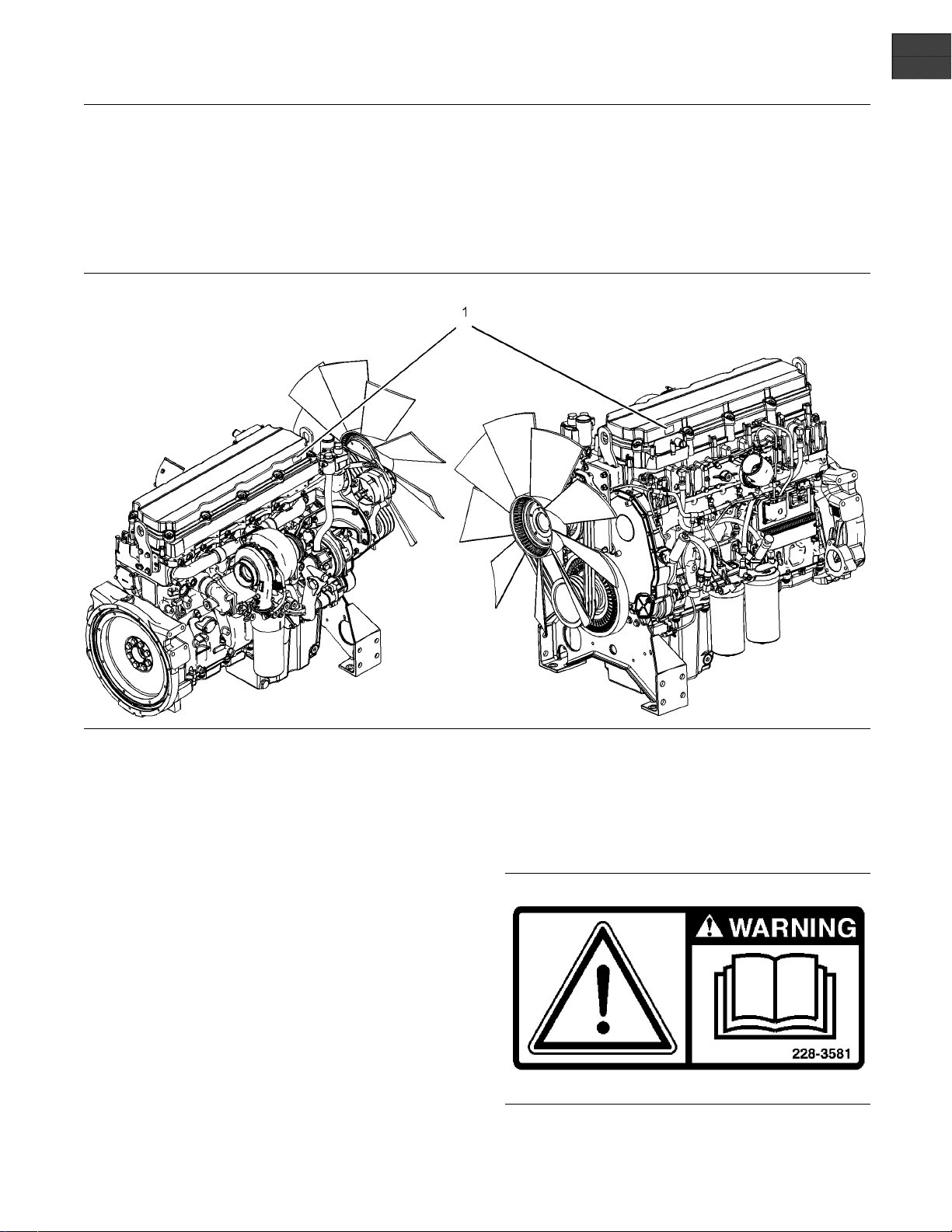
Illustration 1
Location of safety message
There may be several specific safety messages on
your engine. The exact location and a description of
the safety messages are reviewed in this section.
Please become familiar with all safety messages.
Ensure that all of the safety messages are legible.
Clean the safety messages or replace the safety
messages if the words cannot be read or if the
illustrations are not visible. Use a cloth, water,
and soap to clean the safety messages. Do not
use solvents, gasoline, or other harsh chemicals.
Solvents, gasoline, or harsh chemicals could loosen
the adhesive that secures the safety messages. The
safety messages that are loosened could drop off
of the engine.
Replace any safety message that is damaged or
missing. If a safety message is attached to a part
of the engine that is replaced, install a new safety
message on the replacement part. Your Perkins
distributor can provide new safety messages.
g01384682
Universal Warning (1)
The safety message for the universal warning is
locatedonbothsidesofthevalvecoverbase.
Illustration 2
g00934493
Page 6
6 SEBU8337
Safety Section
General Hazard Information
Do not operate or work on this equipment unless
you have read and understand the instructions
and warnings in the Operation and Maintenance
Manuals. Failure to follow the instructions or
heed the warnings could result in serious injury
or death.
i02328435
General Hazard Information
Keep the engine
debris, oil, tools, and other items from the deck, from
walkways, and from steps.
Never put maintenance fluids into glass containers.
Drain all liquids into a suitable container.
Obey all local regulations for the disposal of liquids.
Use all cleani
Report all necessary repairs.
Do not allow unauthorized personnel on the
equipment.
Ensure that the power supply is disconnected before
you work on the bus bar or the glow plugs.
Perform maintenance on the engine with the
equipment in the servicing position. Refer to the
OEM informat
equipment in the servicing position.
free from foreign material. Remove
ng solutions with care.
ionfortheprocedureforplacingthe
Pressure Air and Water
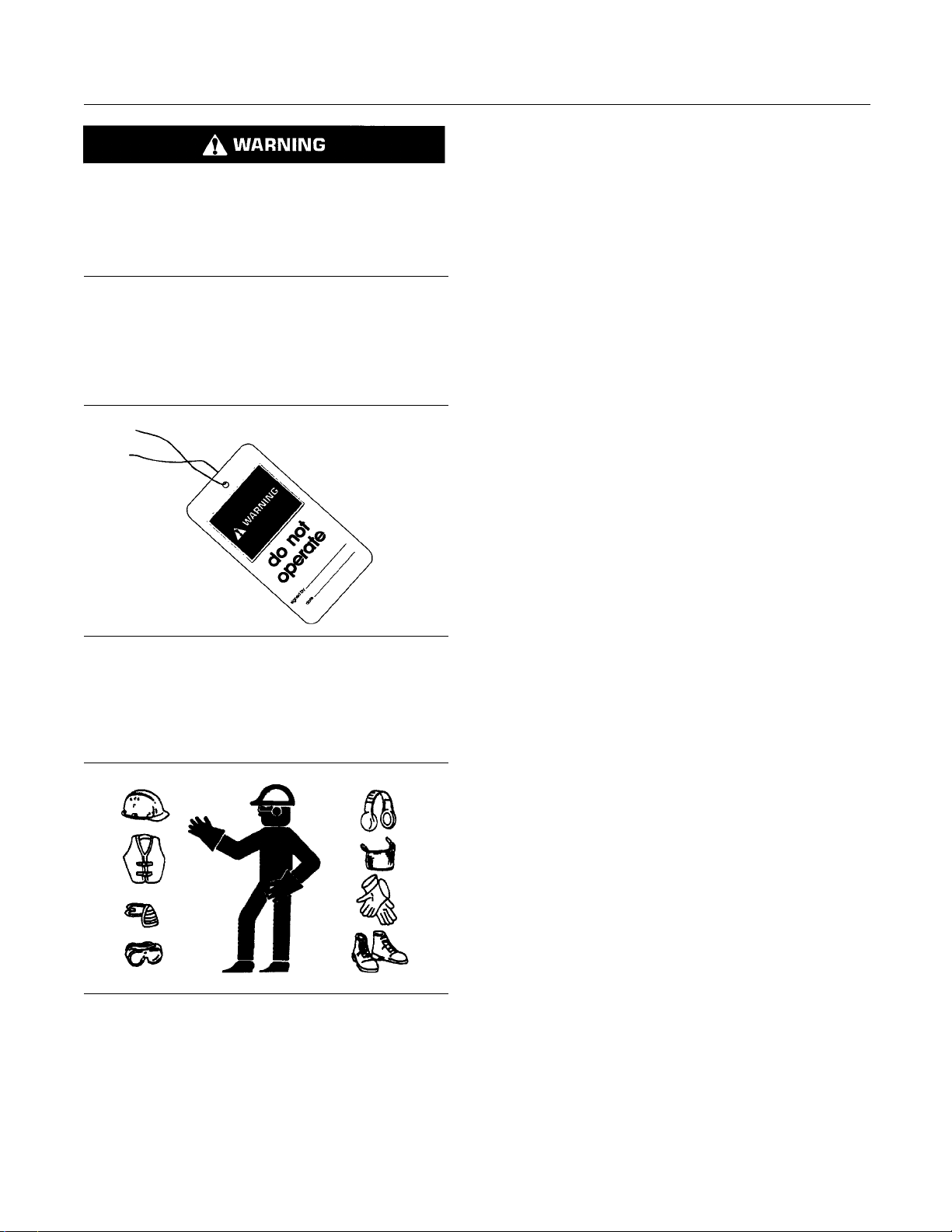
Illustration 3
Attach a “Do Not Operate” warning tag or a similar
warning tag to the start switch or to the controls
before you service the equipment or before you
repair the equipment.
Illustration 4
Wear a hard hat, protective glasses, and other
protective equipment, as required.
Do not wear loose clothing or jewelry that can snag
on controls or on other parts of the engine.
Make sure that all protective guards and all covers
are secured in place on the engine.
g00104545
g00702020
Pressurize
and/or hot water to be blown out. This could result in
personal injury.
The direct application of pressurized air or
pressurized water to the body could result in personal
injury.
When pressurized air and/or water is used for
cleaning,
and eye protection. Eye protection includes goggles
oraprotectivefaceshield.
The maximum air pressure for cleaning purposes
must be below 205 kPa (30 psi). The maximum
water pres
275 kPa (40 psi).
d air and/or water can cause debris
wear protective clothing, protective shoes,
sure for cleaning purposes must be below
Fluid Penetration
Pressure
after the engine has been stopped. The pressure can
cause hydraulic fluid or items such as pipe plugs to
escape ra
Do not remove any hydraulic components or parts
until pre
may occur. Do not disassemble any hydraulic
components or parts until pressure has been relieved
or perso
information for any procedures that are required to
relieve the hydraulic pressure.
can be trapped in the hydraulic circuit long
pidly if the pressure is not relieved correctly.
ssure has been relieved or personal injury
nal injury may occur. Refer to the OEM
Page 7
SEBU8337 7
Safety Section
Burn Prevention
Coolant
When the engine is at operating temperature, the
engine coolant is hot. The coolant is also under
pressure. The radiator and all lines to the heaters or
to the engine contain hot coolant. Any contact with
hot coolant or with steam can cause severe burns.
Allow cooling system components to cool before the
cooling system is drained.
Check the coolant level after the engine has stopped
and the engine has been allowed to cool. Ensure
that the filler cap is cool before removing the filler
cap. The filler cap must be cool enough to touch with
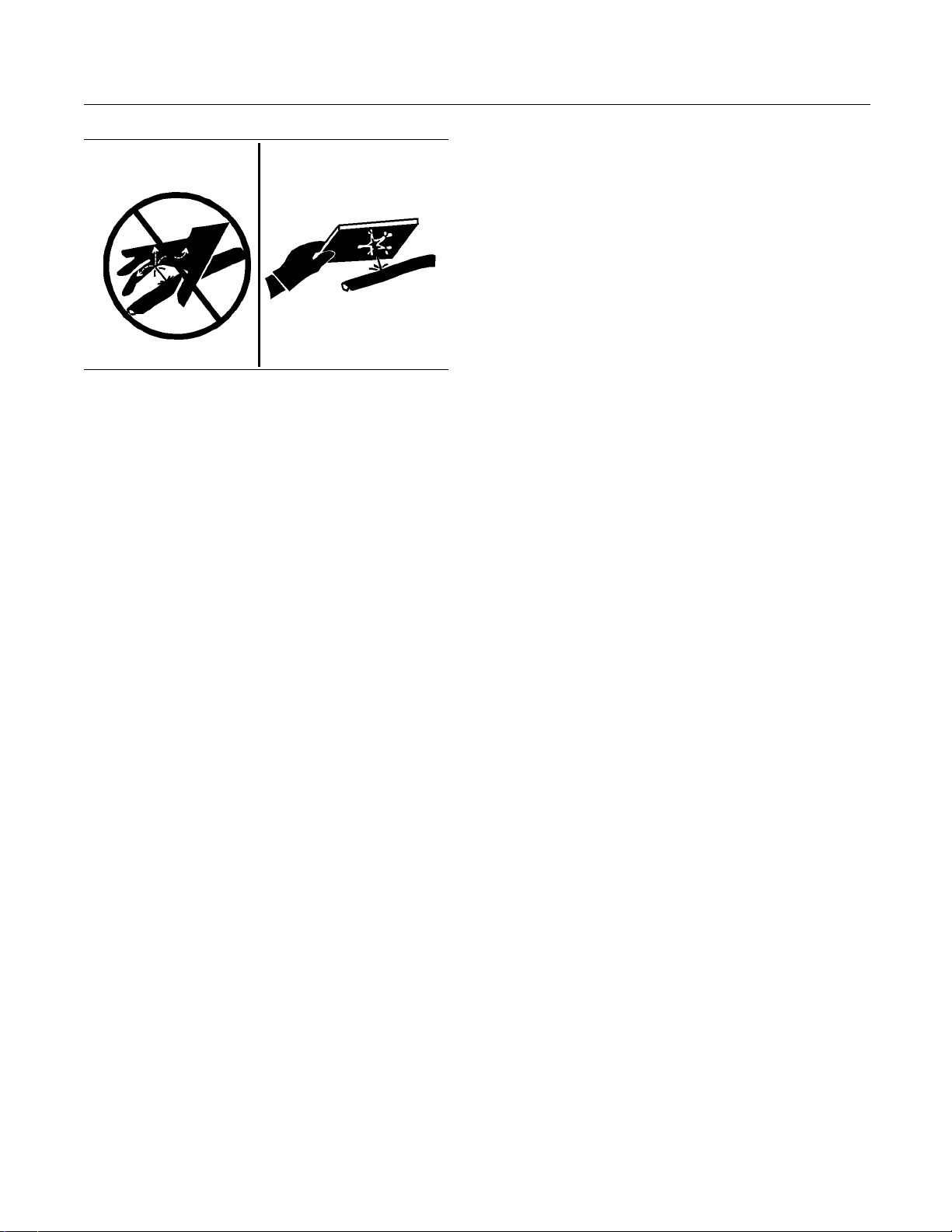
Illustration 5
g00687600
a bare hand. Remove the fillercapslowlyinorder
to relieve pressure.
Always use a board or cardboard when you check
for a leak. Leaking fluid that is under pressure can
penetrate body tissue. Fluid penetration can cause
serious injury and possible death. A pin hole leak can
cause severe injury. If fluid is injected into your skin,
you must get treatment immediately. Seek treatment
from a doctor that is familiar with this type of injury.
Containing Fluid Spillage
Care must be taken in order to ensure that fluids
are contained during performance of inspection,
maintenance, testing, adjusting and repair of the
engine. Make provision to collect the fluidwitha
suitable container before any compartment is opened
or before any component is disassembled.
Only use the tools that are suitable for collecting
•
fluids and equipment that is suitable for collecting
fluids.
Only use the tools that are suitable for containing
•
fluids and equipment that is suitable for containing
fluids.
Obey all local regulations for the disposal of liquids.
i02088921
Cooling system conditioner contains alkali. Alkali can
cause personal injury. Do not allow alkali to contact
the skin, the eyes, or the mouth.
Oils
Hot oil and hot lubricating components can cause
personal injury. Do not allow hot oil or hot components
to contact the skin.
If the application has a makeup tank, remove the cap
for the makeup tank after the engine has stopped.
The filler cap must be cool to the touch.
Batteries
The liquid in a battery is an electrolyte. Electrolyte is
an acid that can cause personal injury. Do not allow
electrolytetocontacttheskinortheeyes.
Do not smoke while checking the battery electrolyte
levels. Batteries give off flammable fumes which can
explode.
Always wear protective glasses when you work with
batteries. Wash hands after touching batteries. The
use of gloves is recommended.
Burn Pre
Do not touch any part of an operating engine.
Allow the engine to cool before any maintenance
is perfo
the appropriate system before any lines, fittings or
related items are disconnected.
rmed on the engine. Relieve all pressure in
vention
Page 8
8 SEBU8337
Safety Section
Fire Prevention and Explosion Prevention
i02813488
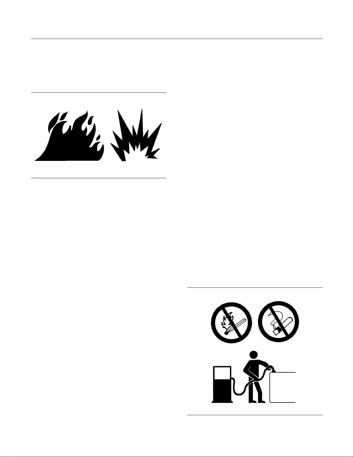
Fire Prevention and Explosion
Prevention
on 6
Illustrati
All fuels, most lubricants, and some coolant mixtures
are flammabl
Flammable fluids that are leaking or spilled onto hot
surfaces or
a fire. Fire may cause personal injury and property
damage.
A flash fire may result if the covers for the engine
crankcase are removed within fifteen minutes after
an emergen
Determine whether the engine will be operated in an
environme
drawn into the air inlet system. These gases could
cause the engine to overspeed. Personal injury,
property
onto electrical components can cause
nt that allows combustible gases to be
damage, or engine damage could result.
g00704000
e.
cy shutdown.
Exhaust shield
s (if equipped) protect hot exhaust
components from oil or fuel spray in case of a line,
a tube, or a seal failure. Exhaust shields must be
installed cor
rectly.
Do not weld on lines or tanks that contain flammable
fluids. Do not
flame cut lines or tanks that contain
flammable fluid. Clean any such lines or tanks
thoroughly with a nonflammable solvent prior to
welding or fla
me cutting.
Wiring must be kept in good condition. All electrical
wires must be
correctly routed and securely attached.
Check all electrical wires daily. Repair any wires
that are loose or frayed before you operate the
engine. Cle
an all electrical connections and tighten
all electrical connections.
Eliminate a
ll wiring that is unattached or unnecessary.
Do not use any wires or cables that are smaller than
the recommended gauge. Do not bypass any fuses
and/or cir
cuit breakers.
Arcing or sparking could cause a fire. Secure
connectio
ns, recommended wiring, and correctly
maintained battery cables will help to prevent arcing
or sparking.
Inspect all lines and hoses for wear or for
deterioration. The hoses must be correctly routed.
The lines
and hoses must have adequate support
and secure clamps. Tighten all connections to the
recommended torque. Leaks can cause fires.
Oil filters and fuel filters must be correctly installed.
The filter housings must be tightened to the correct
torque.
If the application involves the presence of combustible
gases, co
nsult your Perkins dealer and/or your
Perkins distributor for additional information about
suitable protection devices.
Remove all flammable combustible materials or
conductive materials such as fuel, oil, and debris from
the engi
ne. Do not allow any flammable combustible
materials or conductive materials to accumulate on
the engine.
Store fuels and lubricants in correctly marked
containers away from unauthorized persons. Store
oily rag
sandanyflammable materials in protective
containers. Do not smoke in areas that are used for
storing flammable materials.
Do not expose the engine to any flame.
Illustration 7
g00704059
Page 9
SEBU8337 9
Safety Section
Crushing Prevention and Cutting Prevention
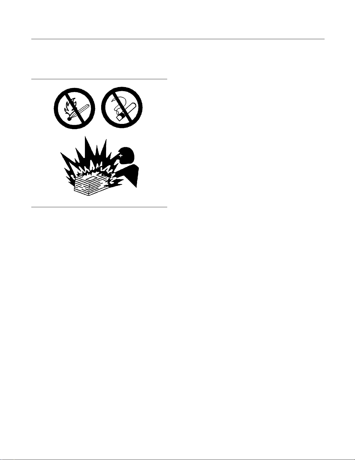
Use caution whe
not smoke while you are refueling an engine. Do not
refuel an engine near open flames or sparks. Always
stop the engin
Illustration 8
Gases from a battery can explode. Keep any open
flames or sparks away from the top of a battery. Do
not smoke in battery charging areas.
Never check the battery charge by placing a metal
object across the terminal posts. Use a voltmeter or
ahydrometer.
Incorrect jumper cable connections can cause
an explosion that can result in injury. Refer to
the Operation Section of this manual for specific
instructions.
n you are refueling an engine. Do
e before refueling.
g00704135
Lines, Tubes and Hoses
Do not bend high
pressure lines. Do not install any lines that are bent
or damaged. Do not clip any other items to the high
pressure line
Repair any lines that are loose or damaged. Leaks
can cause fire
Perkins distributor for repair or for replacement parts.
Check lines,
your bare hand to check for leaks. Use a board or
cardboard to check for leaks. Tighten all connections
to the recomm
Replace the parts if any of the following conditions
are present:
End fittings are damaged or leaking.
•
Outer coverings are chafed or cut.
•
Wires are ex
•
Outer coverings are ballooning.
•
Flexible part of the hoses are kinked.
•
Outer cover
•
End fittings are displaced.
•
Make sure that all clamps, guards, and heat shields
are installed correctly. During engine operation, this
will help to
parts, and excessive heat.
pressure lines. Do not strike high
s.
s. Consult your Perkins dealer or your
tubes and hoses carefully. Do not use
ended torque.
posed.
s have embedded armoring.
prevent vibration, rubbing against other
i01359666
Do not charge a frozen battery. This may cause an
explosion.
The batteries must be kept clean. The covers
(if equipped) must be kept on the cells. Use the
recommended cables, connections, and battery box
covers when the engine is operated.
Fire Extinguisher
Make sure that a fire extinguisher is available. Be
familiar with the operation of the fire extinguisher.
Inspect the fire extinguisher and service the fire
extinguisher regularly. Obey the recommendations
on the instruction plate.
Crushing P
Cutting Prevention
Support the component properly when work beneath
the compon
Unless other maintenance instructions are provided,
never att
running.
Stay clea
parts. Leave the guards in place until maintenance
is performed. After the maintenance is performed,
reinstal
Keep objects away from moving fan blades. The fan
blades w
ent is performed.
empt adjustments while the engine is
r of all rotating parts and of all moving
l the guards.
ill throw objects or cut objects.
revention and
Page 10

10 SEBU8337
Safety Section
Mounting and Dismounting
When objects ar
order to avoid injury to the eyes.
Chips or other
are struck. Before objects are struck, ensure that no
one will be injured by flying debris.
e struck, wear protective glasses in
debris may fly off objects when objects
i01372247
Mounting an d Dismounting
Inspect the steps, the handholds, and the work area
before mounting the engine. Keep these items clean
and keep these items in good repair.
Mount the engine and dismount the engine only at
locations that have steps and/or handholds. Do not
climb on the engine, and do not jump off the engine.
Face the engine in order to mount the engine or
dismount the engine. Maintain a three-point contact
with the steps and handholds. Use two feet and one
hand or use one foot and two hands. Do not use any
controls as handholds.
If equipped, en
engine is suitable for the conditions. Ensure that all
lights work correctly, if equipped.
All protective guards and all protective covers must
be installed if the engine must be started in order
to perform se
accident that is caused by parts in rotation, work
around the parts carefully.
Do not bypass the automatic shutoff circuits. Do not
disable the automatic shutoff circuits. The circuits are
provided in o
circuits are also provided in order to help prevent
engine damage.
See the Service Manual for repairs and for
adjustments.
sure that the lighting system for the
rvice procedures. To help prevent an
rder to help prevent personal injury. The
i02583384
Engine Starting
Do not stand on components which cannot support
your weight. Use an adequate ladder or use a work
platform. Secure the climbing equipment so that the
equipment will not move.
Do not carry tools or supplies when you mount the
engine or when you dismount the engine. Use a hand
line to raise and lower tools or supplies.
i02813489
Before Starting Engine
Before the initial start-up of an engine that is new,
serviced or repaired, make provision to shut the
engine off, in order to stop an overspeed. This may
be accomplished by shutting off the air and/or fuel
supply to the engine.
Overspeed shutdown should occur automatically for
engines that are controlled electronically. If automatic
shutdown does not occur, press the emergency stop
button in order to cut the fuel and/or air to the engine.
Inspect the engine for potential hazards.
Before starting the engine, ensure that no one is on,
underneath, or close to the engine. Ensure that the
area is free of personnel.
Do not use aerosol types of starting aids such as
ether. Such use could result i n an explosion and
personal injury.
If a warning tag is attached to the engine start switch
or to the controls DO NOT start the engine or move
the controls. Consult with the person that attached
the warning tag before the engine is started.
All protective guards and all protective covers must
be installed if the engine must be started in order
to perform service procedures. To help prevent an
accident that is caused by parts in rotation, work
around the parts carefully.
Start the engine from the operator’s compartment or
from the engine start switch.
Always start the engine according to the procedure
that is described in the Operation and Maintenance
Manual, “Engine Starting” topic in the Operation
Section. Knowing the correct procedure will help to
prevent major damage to the engine components.
Knowing the procedure will also help to prevent
personal injury.
To ensure that the jacket water heater (if equipped)
is working correctly, check the water temperature
gauge and/or the oil temperature gauge during the
heater operation.
Page 11
SEBU8337 11
Safety Section
Engine Stopping
Engine exhaust
contains products of combustion
which can be harmful to your health. Always start the
engine and operate the engine in a well ventilated
area. If the en
gine is started in an enclosed area,
vent the engine exhaust to the outside.
Note: The eng
inemaybeequippedwithadevicefor
cold starting. If the engine will be operated in very
cold conditions, then an extra cold starting aid may
be required.
Normally, the engine will be equipped
with the correct type of starting aid for your region
of operation.
i01462046
Engine Stopping
Stop the engine according to the procedure in
the Operat
Stopping (Operation Section)” in order to avoid
overheating of the engine and accelerated wear of
the engine
Use the Emergency Stop Button (if equipped) ONLY
in an emerg
Stop Button for normal engine stopping. After an
emergency stop, DO NOT start the engine until the
problem t
corrected.
Stop the e
during the initial start-up of a new engine or an engine
that has been overhauled. This may be accomplished
by shutt
shutting off the air supply to the engine.
To st o p a
power to the engine.
ion and Maintenance Manual, “Engine
components.
ency situation. Do not use the Emergency
hat caused the emergency stop has been
ngine if an overspeed condition occurs
ing off the fuel supply to the engine and/or
n electronically controlled engine, cut the
Check the elect
rical wires daily for wires that
are loose or frayed. Tighten all loose electrical
connections before the engine is started. Repair all
frayed electr
ical wires before the engine is started.
See the Operation and Maintenance Manual for
specific starting instructions.
Grounding Practice
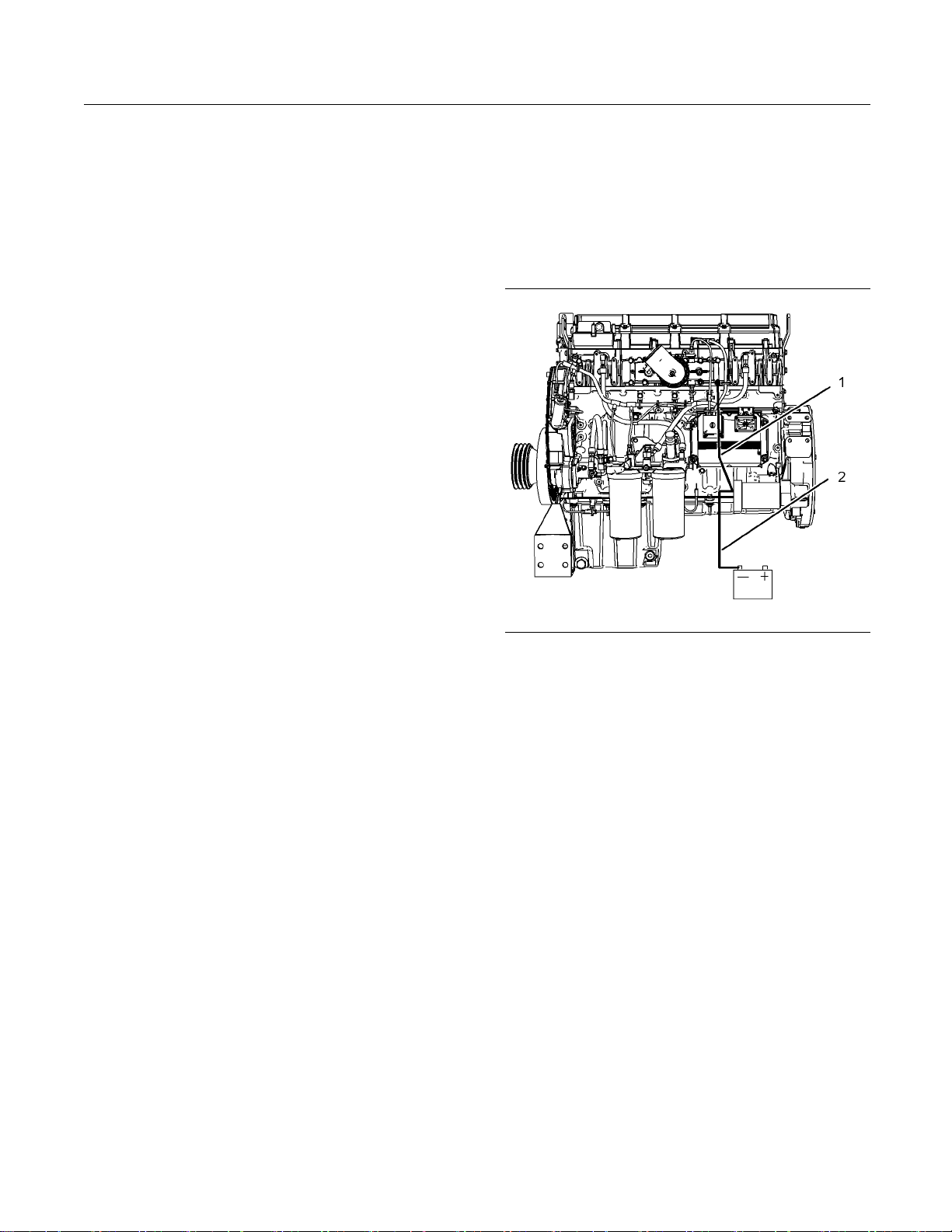
Illustration 9
Typical example
(1) Starting motor to engine block
(2) Starting motor to battery negative
Correct grounding for the engine electrical system
is necessary for optimum engine performance
and reliability. Incorrect grounding will result in
uncontrolled electrical circuit paths and in unreliable
electrical circuit paths.
g01403749
i02814681
Electrical System
Never disconnect any charging unit circuit or battery
circuit cable from the battery when the charging unit
is operating. A spark can cause the combustible
gases that are produced by some batteries to ignite.
To help prevent sparks from igniting combustible
gases that are produced by some batteries, the
negative “−” cable should be connected last from the
external power source to the negative “−” terminal
of the starting motor. If the starting motor is not
equipped with a negative “−” terminal, connect the
cable to the engine block.
Uncontrolled electrical circuit paths can result in
damage to the crankshaft bearing journal surfaces
and to aluminum components.
Engines that are installed without engine-to-frame
ground straps can be damaged by electrical
discharge.
To ensure that the engine and the engine electrical
systems function correctly, an engine-to-frame
ground strap with a direct path to the battery must be
used. This path may be provided by way of a direct
engine ground to the frame.
The connections for the grounds should be tight and
free of corrosion. The engine alternator must be
grounded to the negative “-” battery terminal with
a wire that is adequate to handle the full charging
current of the alternator.
Page 12

12 SEBU8337
Safety Section
Engine Electronics
The power suppl
connections for the engine electronics should always
be from the isolator to the battery.
y connections and the ground
i02773399
Engine Electron ics
Tampering with the electronic system installation
or the OEM wiring installation can be dangerous
andcouldres
engine damage.
This engine h
Engine Monitoring System. The Engine Control
Module (ECM) has the ability to monitor the engine
operating c
extend outside an allowable range, the ECM will
initiate an immediate action.
The following actions are available for engine
monitoring control: WARNING, ACTION ALERT, and
SHUTDOWN.
ult in personal injury or death and/or
as a comprehensive, programmable
onditions. If any of the engine parameters
Many of the parameters that are monitored by the
ECM can be p
functions. The following parameters can be monitored
as a part of the Engine Monitoring System:
Atmospheric Pressure
•
Intake Man
•
Coolant Temperature
•
Engine Oil Pressure
•
Crankshaf
•
Camshaft Position
•
Fuel Temperature
•
Intake Ma
•
System Voltage
•
The Engine Monitoring package can vary for different
engine models and different engine applications.
However,
monitoring control will be similar for all engines.
rogrammed for the engine monitoring
ifold Air Pressure
tPosition
nifold Temperature
the monitoring system and the engine
Page 13
SEBU8337 13
Product Information Section
General Information
Product Information
Section
General Information
i01889424
Welding on Engines with
Electronic Controls
NOTICE
Proper welding procedures are necessary in order
to avoid damage to the engine’s ECM, sensors, and
associated components. When possible, remove the
component from the unit and then weld the component. If removal of the component is not possible,
the following procedure must be followed when you
weld with a unit that is equipped with an Electronic
Engine. The following procedure is considered to be
the safest procedure to weld a component. This procedure should provide a minimum risk of damage to
electronic components.
NOTICE
Do not ground the welder to electrical components
such as the ECM or sensors. Improper grounding can
cause damage to the drive train bearings, hydraulic
components, electrical components, and other components.
Clamp the ground cable from the welder to the component that will be welded. Place the clamp as close
as possible to the weld. This will help reduce the possibility of damage.
1. Stop the engine. Turn the switched power to the
OFF position.
2. Disconnect the negative battery cable from the
battery. If a battery disconnect switch is provided,
open the switch.
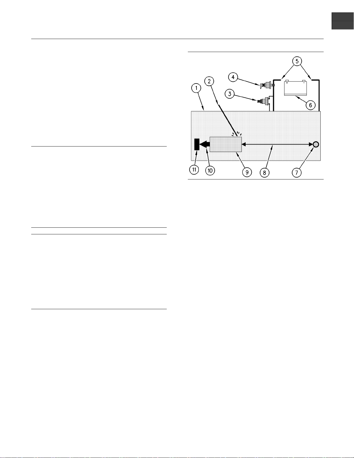
Illustration 10
Use the example above. The current flow from the welder to
the ground clamp of the welder will not cause damage to any
associated components.
(1) Engine
(2) Welding rod
(3) Keysw itch in the OFF position
(4) Battery disconnect switch in the open position
(5) Disconnected battery cables
(6) Battery
(7) Electrical/Electronic com ponent
(8) Maximum distance between the component that is being
welded and any electrical/electronic component
(9) The component that is being welded
(10) Current path of the welder
(11) Ground clamp for the welder
g00765012
4. Connect the welding ground cable directly to the
part that will be welded. Place the ground cable as
close as possible to the weld in order to reduce the
possibility of welding current damage to bearings,
hydraulic components, electrical components, and
ground straps.
Note: If electrical/electronic components are used
as a ground for the welder, or electrical/electronic
components are located between the welder ground
and the weld, current fl ow from the welder could
severely damage the component.
3. Disconnect the J1/P1 connectors from the ECM.
Move the harness to a position that will not allow
the harness to accidentally move back and make
contact with any of the ECM pins.
5. Protect the wiring harness from welding debris
and spatter.
6. Use standard welding practices to weld the
materials.
Page 14
14 SEBU8337
Product Information Section
Model Views
Model Views
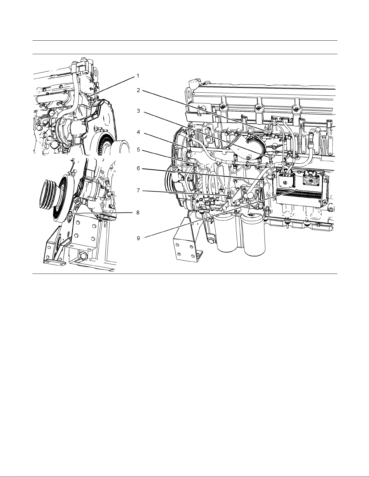
i02770579
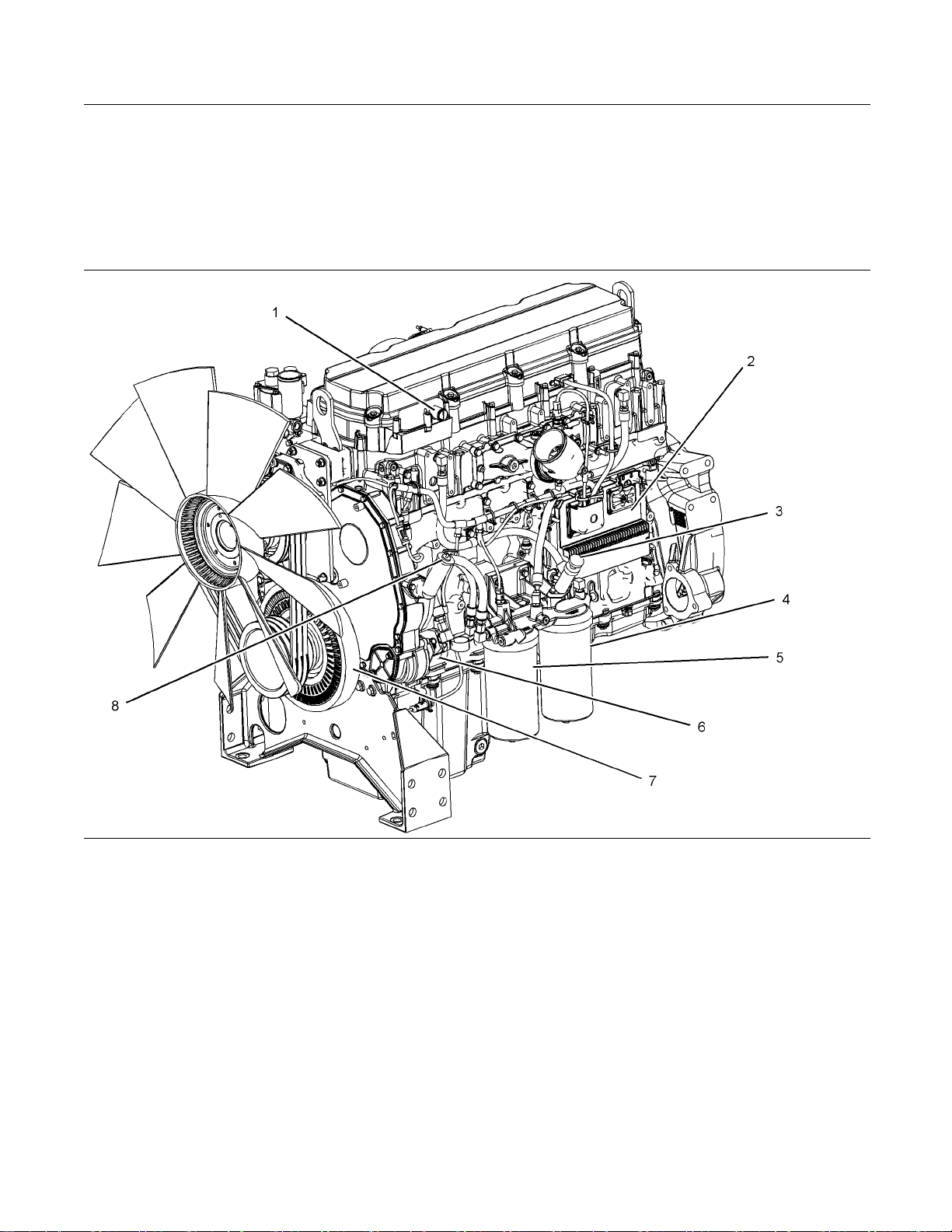
Model View Illustrations
Illustration 11
Typical example
Left side engine view
(1) Connection for the breather
(2) Electronic control module (ECM)
(3) Fuel priming pump
(4) Secondary fuel filter
(5) Pr imary f u el filter
(6) Fuel pump
g01385634
(7) Crankshaft damper
(8) Oil fi ller
Page 15
SEBU8337 15
Product Information Section
Model Views
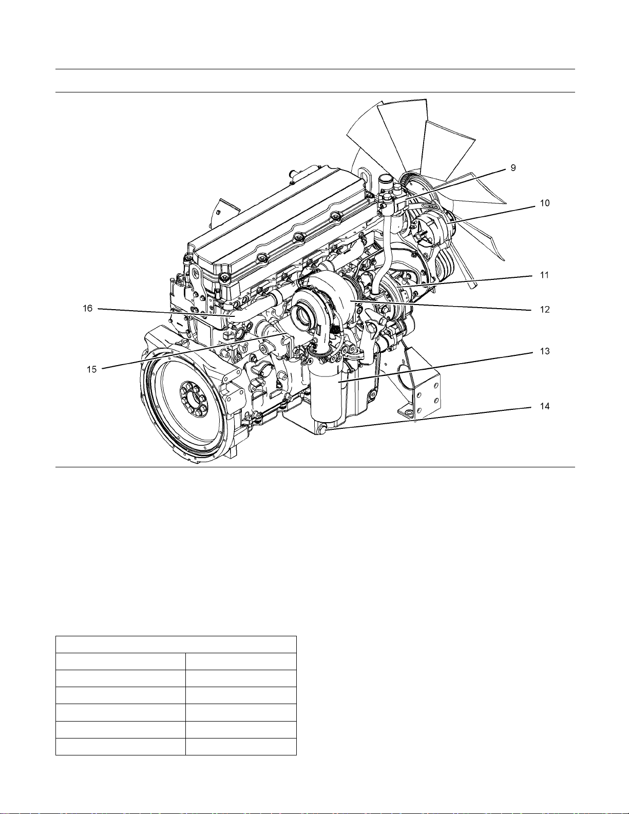
Illustration 1 2
Typical example
Right side engine view
(9) Water temperature regulator housing
(10) Alternator
(11) Water pump
(12) Turbocharger
(13) Oil filter
(14) Oil drain plug
Engine Description
Table 1
2206 Engine Specifications
Cylinders and Arrangement In-line six cylinder
Bore 130 mm (5.2 inch)
Stroke 157 mm (6.2 inch)
Displacement
Firing Order
Rotation (flywheel end) Counterclockwise
12.5 L (7
63 in3)
1-5-3-6-2-4
i02770677
g01385635
(15) Oil cooler
(16) Exhaust manifold
The electronic engines that are covered by this
manual have the following characteristics: direct fuel
injection, electronic unit injection that is mechanically
actuated, turbocharged, and air-to-air aftercooled
(ATAAC).
The electronic engine control system provides the
following functions: electronic governing, automatic
air to fuel ratio control, injection timing control, and
system diagnostics.
An electronic governor controls the output of the unit
injectors in order to maintain the engine rpm that is
desired.
Page 16

16 SEBU8337
Product Information Section
Model Views
Very high injec
electronically controlled, mechanically actuated unit
injectors. The injectors combine the pumping and the
electronic fu
injection. The unit injectors accurately control smoke
limiting, white smoke, and engine acceleration rates.
There is one unit injector per cylinder. Individual unit
injectors meter the fuel. The individual unit injectors
also pump the
done under high pressure. High injection pressures
help to reduce fuel consumption and emissions.
The use of th
electronic control of injection timing. The injection
timing varies with engine operating conditions. The
engine perf
areas:
Starting
•
Emissions
•
Noise
•
Fuel consu
•
The timing advance is achieved through precise
control of
controlled by adjusting the firing duration. The
information is provided to the Electronic Control
Module (EC
the camshaft position sensor. The information is for
detection of cylinder position and engine speed.
tion pressures are produced by
el metering (duration and timing) during
fuel. The metering and the pumping is
is type of unit injector provides total
ormance is optimized in the following
mption
the injector firing. Engine speed is
M) by the crankshaft position sensor and
Engine efficien
engine performance depend on adherence to proper
operation and maintenance recommendations. This
includes the u
and lubrication oils.
cy, efficiency of emission controls, and
se of recommended fuels, coolants
Aftermarket Products and Perkins
Engines
When auxiliary devices, accessories, or consumables
(filters, add
other manufacturers are used on Perkins products,
the Perkins warranty is not affected simply because
of such use.
However, failures that result from the installation
or use of oth
accessories, or consumables are NOT Perkins
defects. Therefore, the defects are NOT covered
under the P
itives, catalysts, etc) which are made by
er manufacturers’ devices,
erkins warranty.
The engines have built-in diagnostics in order to
ensure that all of the components are functioning
and opera
component deviation from the programmed limits,
the operator will be alerted to the condition by a
DIAGNOS
panel. An electronic service tool that is provided by
Perkins may be used to read the diagnostic codes.
These co
Refer to Operation and Maintenance Manual, “Engine
Diagnostics” for additional information.
The cooling system consists of the following items:
a centrifugal pump that is driven by a gear, water
temper
that incorporates a shunt system.
The eng
type pump. The engine lubricating oil is cooled and
filtered. Bypass valves provide unrestricted flow
of lub
viscosity is high or if either the oil cooler or the oil
filter elements (paper cartridge) become plugged.
ting properly. In the event of a system
TIC lamp that is mounted on the control
des are logged and stored in the ECM.
ature regulator, an oil cooler, and a radiator
ine lubricating oil is supplied by a gear
rication oil to the engine parts when the oil
Page 17
SEBU8337 17
Product Information Section
Product Identification Information
Product Identification
Information
i02770689
Plate Locations and Film
Locations
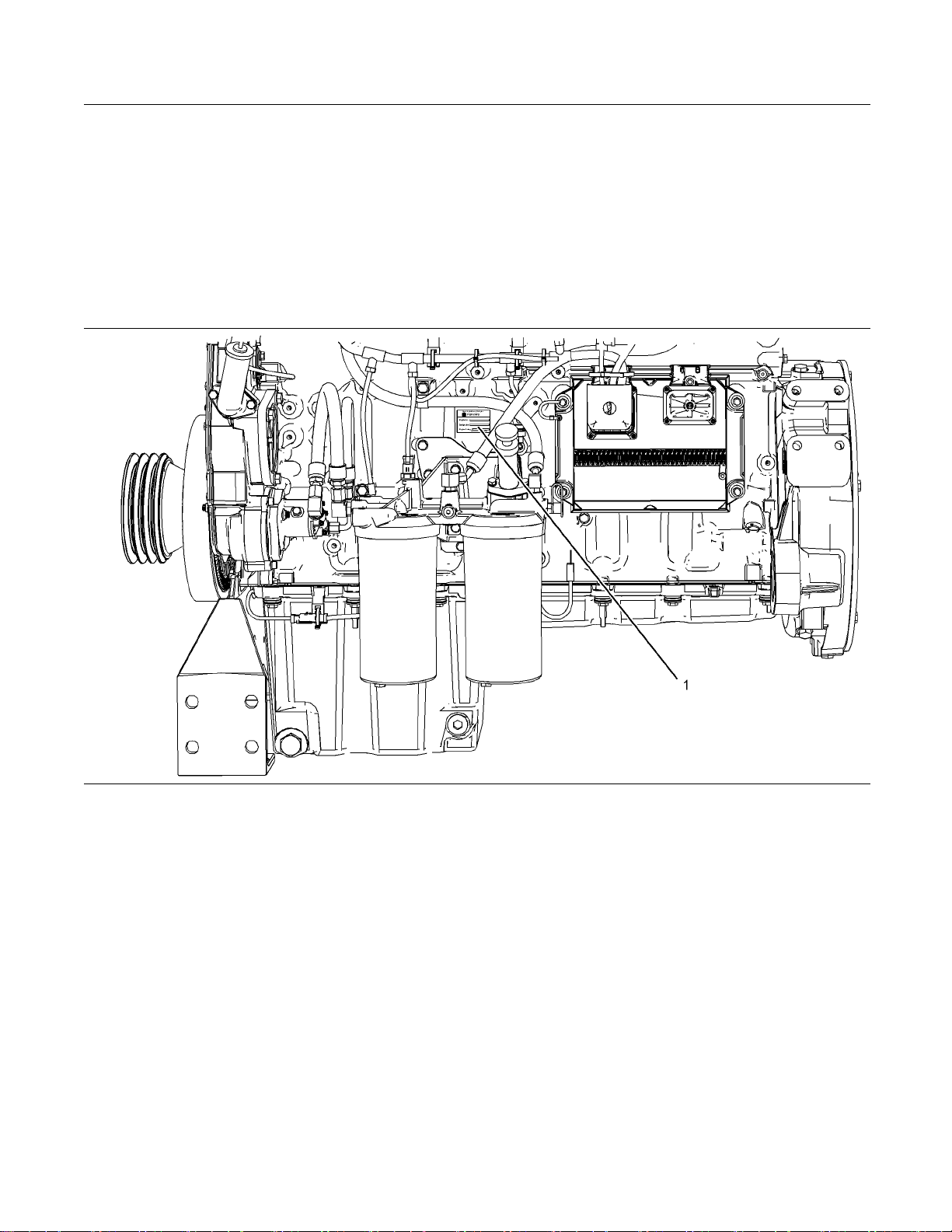
Illustration 1 3
(1) Serial number plate
s engines are identified by serial numbers.
Perkin
These numbers are shown on the engine serial
number plate. Perkins distributors need these
number
were included with the engine. This permits accurate
identification of replacement part numbers.
s in order to determine the components that
g013856
86
Page 18
18 SEBU8337
Product Information Section
Product Identification Information
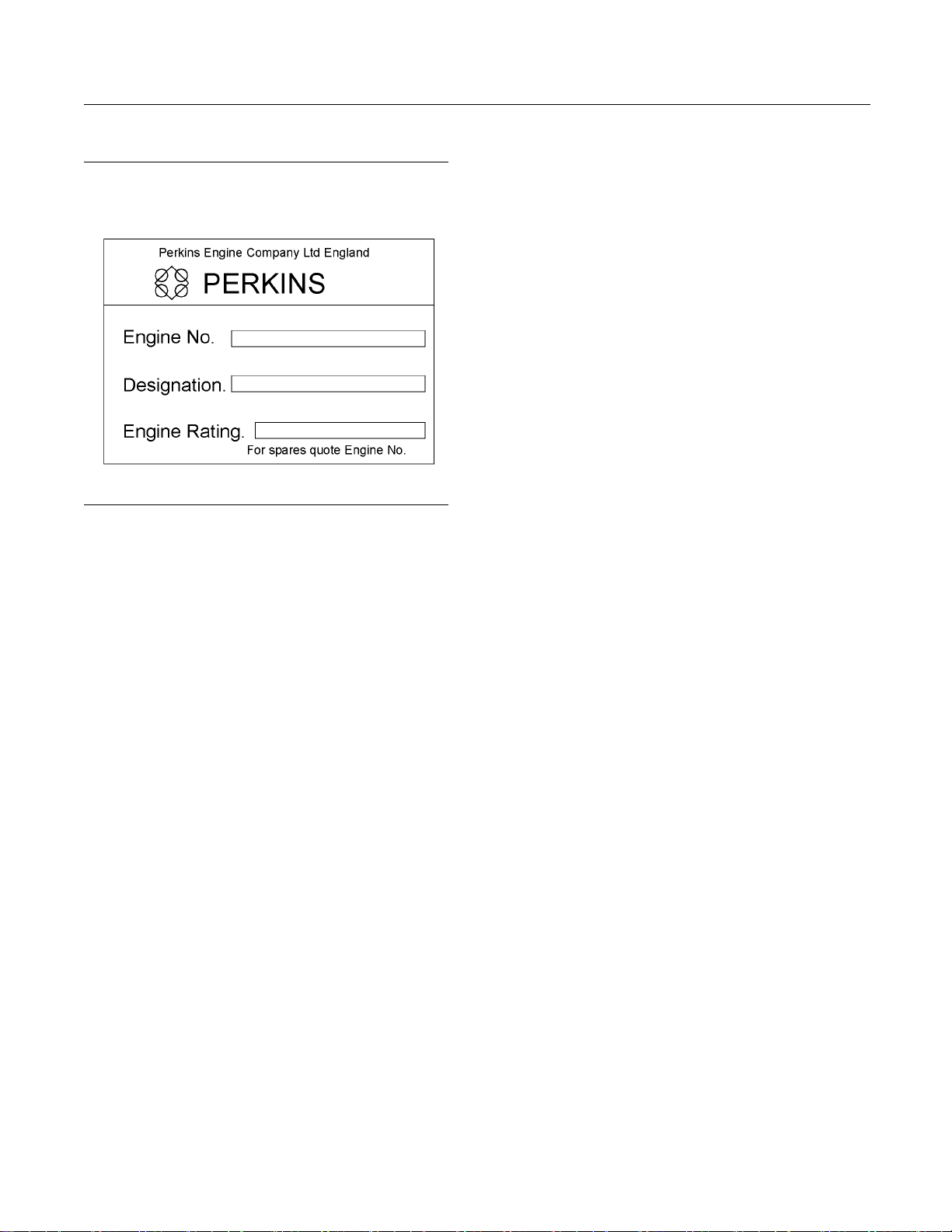
Serial Number Plate (1)
Illustration 14
Typical exam ple
The engine serial number plate is located on the right
side of the engine block.
g01403841
Tot a l Lu br ic at
ion System Capacity
_____________________
Total Cooling System Capacity _________________________
Air Cleaner Element _______________________________________
Fan Drive Belt
______________________________________________
Alternator Belt ______________________________________________
Engine serial number
_____________________________________
Designation _________________________________________________
Engine Rating ________ ______________________________________
i02563635
Reference Numbers
Information for the following items may be needed to
order parts. Locate the information for your engine.
Record the information in the appropriate space.
Make a copy of this list for a record. Keep the
information for future reference.
Record for Reference
Engine Model _______ ________________________________________
Engine Serial number _____________________________________
Engine rpm __________________________________________________
Primary Fuel Filter _________________________________________
Secondary Fuel Filter Element ___ _______________________
Lubrication Oil Filter Element ___________________________
Page 19
SEBU8337 19
Product Information Section
Product Identification Information
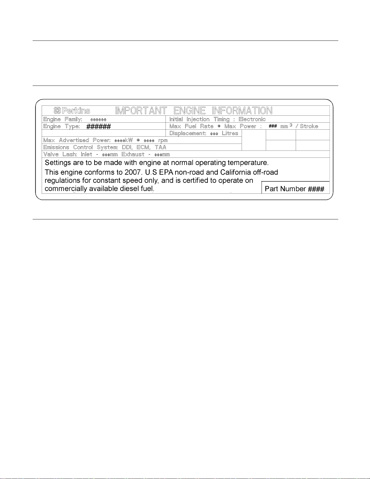
i02770895
Emissions Certification Film
Illustration 1 5
Typical example
The emission certification film is located on the left
hand side of the valve mechanism cover.
i02817239
Customer Specified
Parameters
To record programmed specifications, use the
following blanks.
Customer Passwords (If required).
First Password _______________________________________ ____
•
Second Password ________________________________ ______
•
Rating Selection (L-N) _____________________________ _____
Equipment ID ______________________________________________
g01385765
Programmable Monitoring System
(PMS)
The Programmable Monitoring System determines
the level of action that is taken by the ECM in
response to a condition that can damage the engine.
These conditions are identified by the ECM from the
signals that are produced from the following sensors.
Inlet Manifold Temperature Sensor
•
Coolant Temperature Sensor
•
Engine Oil Pressure Sensor
•
Engine Crankshaft/Camshaft Sensors
•
Inlet Manifold Pressure Sensor
•
Fuel Temperature Sensor
•
Page 20

20 SEBU8337
Product Information Section
Product Identification Information
Table 2
Event Code Parameter State Trip Point Delay Time
E162 High Boost Pressure
-1
-2
E360
-1
-2
-3
E361
-1 Warn Operator (1) On 104 °C (2190 °F) 60 seconds
-2 Action Alert (2) Always On 105 °C (221 °F) 10 seconds
-3 Engine Shutdown (3) Always On 108 °C (226 °F) 10 seconds
E362
-1
-2
-3
E363
-1
-2
E368
-1
-2 Action Alert (2) Always On 78 °C (172 °F) 10 seconds
Warn Operator (1) On 300 kPa (43.5 psi)
Action Alert (2) Always On
Low Engine Oil Pressure
Warn Operator (1) On 200 kPa (29 psi)
Action Alert (2) Always On
Engine Shutdown (3) Always On
High Engine Coolant Temperature
Engine Overs
Warn Operator (1) On
Action Alert (2) Always On
Engine Shutdown (3) Always On
High Fuel Supply Temperature
Warn Operator (1) On 60 °C (140 °F)
Action Alert (2) Always O n 68 °C (154 °F)
High Engine Intake Manifold Air Temperature
Warn Operator (1) On 75 °C (167 °F)
peed
Map 5 seconds
Map 2 seconds
Map 2 seconds
2000 RPM 1 second
2050 RPM 0 second
2140 RPM 0 second
60 seconds
60 seconds
60 seconds
60 seconds
60 seconds
Refer to Troubleshooting , “System Confi guration
Parameters” for additional information for the
Programmable Monitoring System.
Page 21
SEBU8337 21
Operation Section
Lifting and Storage
Operation Section
Lifting and Storage
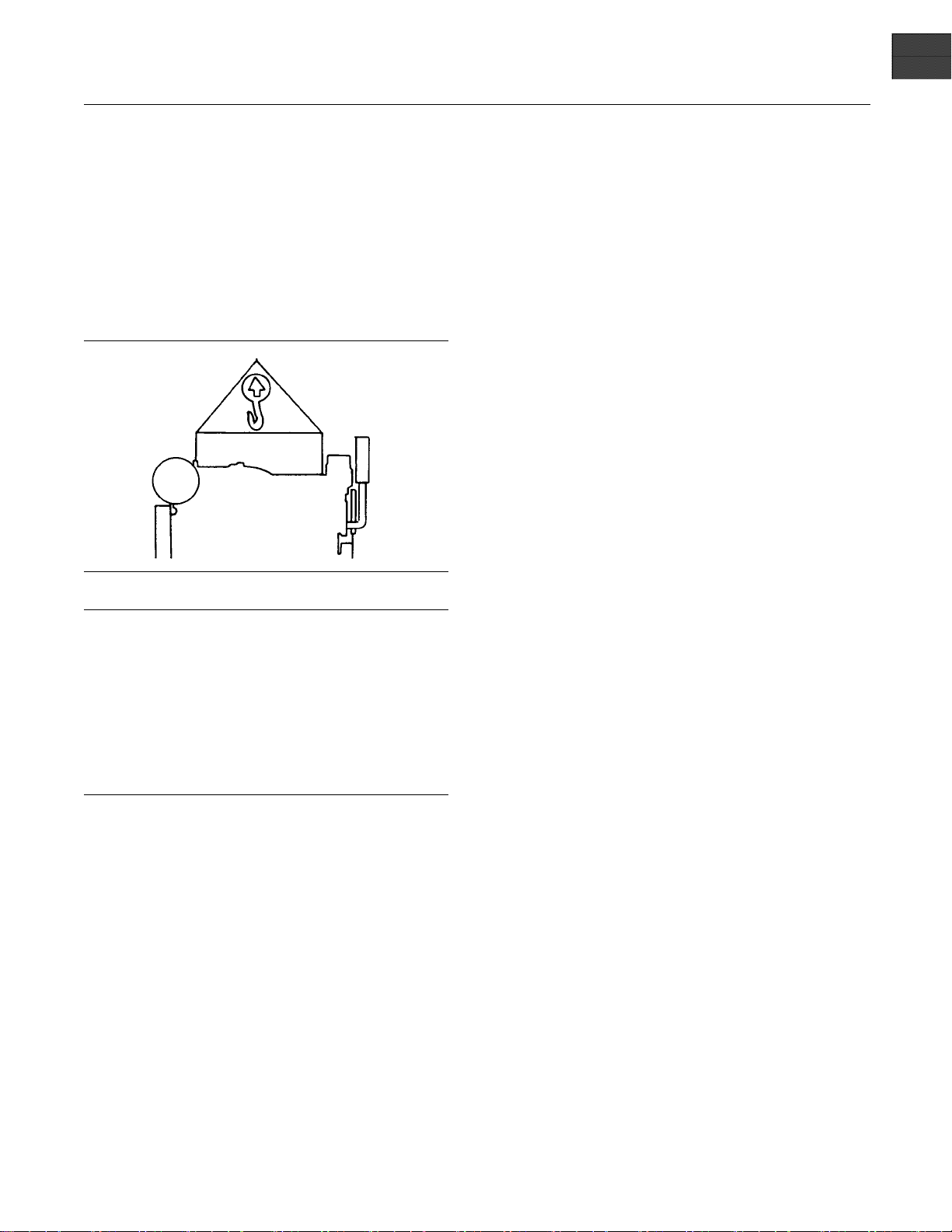
Product Lifting
Illustration 16
i02513632
g00103219
i02848873
Product St orag e
Refer to Perkin
for information on engine storage.
There is three
Level “A, B and C”.
Level “A ”
Level “A” will
engines and 12 month protection for gas engines.
This is for engines that are transported by a container
or a truck. Le
that are within the United kingdom and within Europe.
Level “B ”
This level is
give protection under normal storage condition
from −15° to +55°C (5° to 99°F) and “90%”
relative hu
transportation of items overseas.
s Engine Company limited, Stafford
different levels of engine storage.
give protection for 12 month for diesel
vel “A” is for the transportation of items
additional to level “A”. Level “B ” will
midity for two year. Level “B” is for the
NOTICE
Never bend the eyebolts and the brackets. Only load
the eyebolts and the brackets under tension. Remember that the capacity of an eyebolt is less as the angle
between the supporting members and the object becomes less than 90 degrees.
When it is necessary to remove a component at an
angle, only use a link bracket that is properly rated for
the weight.
Use a hoist to remove heavy components. Use
an adjustable lifting beam to lift the engine. All
supporting members (chains and cables) should be
parallel to each other. The chains and cables should
be perpendicular to the top of the object that is being
lifted.
Some removals require lifting the fi xtures in order to
obtain proper balance and safety.
ToremovetheengineONLY,usetheliftingeyesthat
are on the engine.
Lifting eyes are designed and installed for specific
engine arrangements. Alterations to the lifting eyes
and/or the engine make the lifting eyes and the lifting
fixtures obsolete. If alterations are made, ensure
that proper lifting devices are provided. Consult your
Perkins dealer for information regarding fixtures for
proper engine lifting.
Level “C ”
In order to p
Perkins Engines Company Limited Stafford.
rotect the product to Level “C”, contact
Page 22
22 SEBU8337
Operation Section
Gauges and Indicators
Gauges and Indicators
i02773410
Gauges and Indicators
Your engine m
the gauges that are described. For more information
about the gauge package, see the OEM information.
Gauges provide indications of engine performance.
Ensure that the gauges are in good working order.
Determine th
the gauges over a period of time.
Noticeable c
potential gauge or engine problems. Problems may
also be indicated by gauge readings that change
even if the r
Determine and correct the cause of any significant
change in the readings. Consult your Perkins
distribut
If no oil pressure is indicated, STOP the engine. If
maximum coolant temperature is exceeded, STOP
the engine
ay not have the same gauges or all of
e normal operating range by observing
hanges in gauge readings indicate
eadings are within specifications.
or for assistance.
NOTICE
. Engine damage can result.
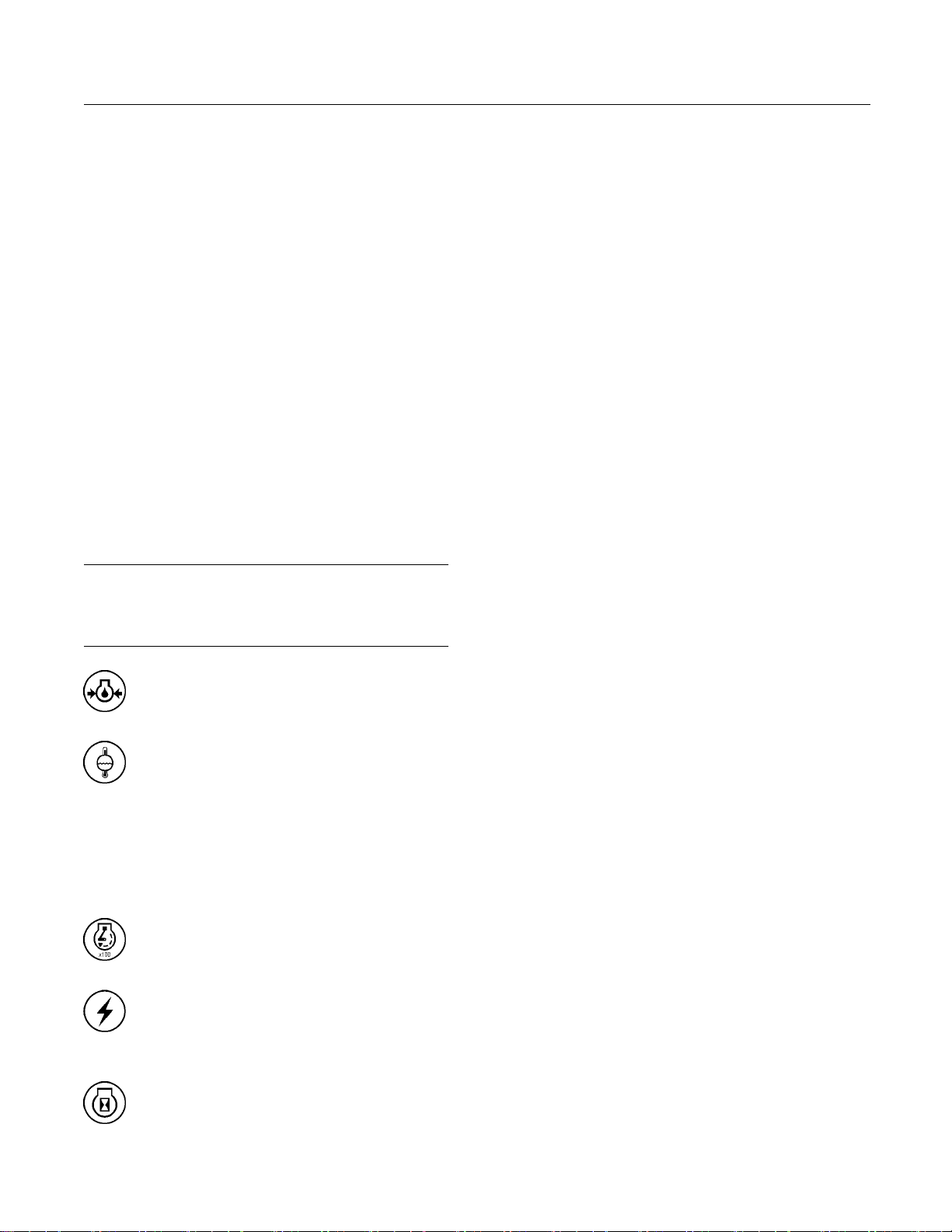
Engine Oil Pressure – The range for the
engine oil
pressure is 420 kPa (61 psi).
Jacket Wat
Typical water temperature into the engine
is 88 °C (190 °F). Higher temperatures
may occur u
temperature reading may vary according to load. The
reading should never exceed 107 °C (224 °F).
1. Ahighwate
cooling system.
indicator should be to the right side of “0” (zero).
nder certain conditions. The water
Tachomete
speed (rpm).
Ammeter – This gauge indicates the
amount of charge or discharge in the
battery charging circuit. Operation of the
Service Hour M eter – The gauge indicates
operating hours of the engine.
er Coolant Temperature –
r temperature switch is installed in the
r–This gauge indicates engine
Page 23

SEBU8337 23
Operation Section
Features and Controls
Features and Controls
i02780670
Monitoring System
The engine has protection in three stages:
Warning
•
Action Alert
•
Shutdown
•
The engine protection may be overridden by the
critical condition mode.
The Electronic Control Module (ECM) monitors the
following parameters:
Engine Temperatures
•
Engine Pressures
•
Engine Speed
•
If the parameters exceed a trip point for a period of
time that is longer than the delay period, the ECM
logs an event code and the indicator switches ON.
The following parameters are monitored for event
codes:
Lubricating Oil Pressure
•
Coolant Temperature
•
Overspeed
•
Intake Manifold Temperature
•
Intake Manifold Pressure
•
Fuel Temperature
•
The temperature protection is disabled for a period
of time when the engine is cranking in order to
compensate for heat soak solutions.
Warning Alarm
The Warning ala
is approaching a critical condition.
If the engine is
event will be logged in the memory of the ECM.
A event code will be transmitted over the Perkins
Data link and
energized. If the engine is in the Warning condition,
the event code and output will remain while the
condition ex
remove the event code from the memory of the ECM.
ThetrippointfortheWarningalarmwillbesettoa
factory def
toolmaybeusedtoalterthetrippointforaWarning
within predefined limits.
rm informs the user that the engine
in the Warning condition, then the
the hard wired Warning output will be
ists. The electronic service tool is used to
ault in production. The electronic service
Action Alert
The Action Alert informs the OEM that the engine is
approaching a critical condition. The engine should
be stopped
the engine may result in an immediate shutdown.
If the engi
will be logged in the memory of the ECM. A event
code will be transmitted over the Perkins Data link
and the har
the engine is in the Action Alert condition the event
code and output will remain while the condition exists.
The event
of the ECM without using a factory password.
in a controlled manner. Further running of
ne is in the Action Alert condition, the event
d wired Action Alert will be energized. If
code can not be cleared from the memory
Shutdown
If the eng
the following events has occurred: low lubricating oil
pressure, high coolant temperature or overspeed.
The even
The engine will be shut down. A event code will
be transmitted over the Perkins Data link and the
hard wir
Shutdown condition will latch until the ECM is reset.
The event code for the shutdown can not be cleared
from th
password.
ine reaches the Shutdown condition,one of
t will be logged in the memory of the ECM.
ed Shutdown output will be energized. The
e memory of the ECM without using a factory
Critical Protection Override
The ECM has dedicated alarm outputs for each of the
three stages of protection. There are also dedicated
alarm outputs for oil pressure, coolant temperature
and overspeed events which are energized at any
stage of protection.
If the e
safety, the protection system can be overridden in
order to ensure the continuation of the power supply
durin
ngine is in an application that is critical for
g engine fault conditions.
Page 24

24 SEBU8337
Operation Section
Features and Controls
Critical Prote
input from the OEM. For example, this may be
a switch to battery + in order to disable a critical
override. Cri
enabled in the electronic service tool by use of a
factory password.
When the Critical Protection Override feature is
active, the ECM will continue to run the engine in all
shutdown con
shutdown. If the shutdown is overridden a event code
is generated. The ECM will log the event code. The
ECM will ene
Alert, Shutdown, oil pressure, coolant temperature,
and overspeed outputs as normal. The warranty of
theenginew
in the following conditions: active event code and
Critical Protection Override mode.
ctionOverridewillbesetbyaswitch
tical Protection Override input can be
ditions with the exception of Overspeed
rgize the following: Warning, Action
ill be invalidated if the engine is operated
Standard Warning Outputs
The ECM provides individual outputs in order to
drive warning lamps or relays to indicate each of the
following
Diagnostic Fault
•
Oil Pressure
•
Coolant Te
•
Overspeed
•
Action Alert
•
Warning
•
Shutdown
•
If the ECM detects a warning for the coolant
temperature , the output on the coolant temperature
will be en
energized. If the ECM detects a warning for the low
oil pressure, the output on the oil pressure will be
energize
If the Action Alert alarms are enabled and the ECM
detects a
on the coolant Temperature will be energized and the
output on the Action Alert will be energized.
If the engine shuts down on low oil pressure the
output on the low oil pressure will be energized and
the outp
engine shuts down on coolant temperature or the
engine shuts down on overspeed the dedicated
output
fault conditions:
mperature
ergized and the warning output will be
d and the warning output will be energized.
coolant temperature condition, the output
ut on the shutdown will be energized. If the
and the shutdown output will be energized.
Shutdown Reset
The cause of an engine shutdown must be
investigated. Corrective action must be taken before
the system is reset in order to operate the engine.
After an engine shutdown, operate the reset input of
the ECM or power down the controller.
Powering down the electronic control module can be
achieved by the operation of the keyswitch into sleep
mode. The electronic control module can be powered
down by isolating the power supply to the electronic
control module.
Note: It is not possible to reset the ECM by using the
Reset input until the engine has come to rest.
Altitude derate
At high altitudes or high ambient temperatures, the
engine will be derated. The engine derate information
can be obtained from the Applications Department at
Perkins Engines Company Limited Stafford.
Diagnostic
If there is a fault with an engine protection sensor on
the engine, the engine activates a diagnostic code.
The engine communicates the diagnostic code to the
operator via the Diagnostic output. The diagnostic
code provides an indication to the operator of a fault
with the engine protection system. Running of the
engine for a prolonged period in this condition may
result in engine failure. The output is generally used
to drive lamps or relays.
The following sensors are monitored in order to
determine if the sensors are out of the normal range,
an open circuit or a short circuit:
Atmosphere Pressure
•
Lubricating Oil Pressure
•
Inlet Manifold Pressure
•
Inlet Manifold Temperature
•
Fuel Temperature
•
Coolant Temperature
•
Engine Speed
•
Desired Speed Input
•
Page 25

SEBU8337 25
Operation Section
Features and Controls
The Diagnostic
Shutdown outputs. The Warning and Shutdown
outputs refer to the operation of the engine. The
Diagnostic ou
electronic system and software system.
A diagnostic
oil pressure or coolant temperature sensors. For
example, if a Shutdown protection sensor has a fault,
this will res
system is in critical protection override. If a diagnostic
fault occurs with one of the engine speed sensors
while the en
run by using the other timing sensor for reference.
output differs from the Warning and
tput refers to the condition of the
fault may develop on the lubricating
ult in an engine shutdown, unless the
gine is running. The engine continues to
i02772006
Sensors and Electrical
Components
Sensor Locations
Illustration 17 shows the typical locations of the
sensors on the engine. Specific engines may appear
different from the illustration due to differences in
applications.
Page 26
26 SEBU8337
Operation Section
Features and Controls
Illustration 1 7
(1) Engine coolant temperature sensor
(2) Intake m anifold pressure sensor
(3) Intake manifold air temperature sensor
(4) Atmospheric pressure sensor
(5) Secondary position sensor (Camshaft)
(6) Engine o il pressure sensor
Failure of Sensors
All Sensors
A failure of any of the sensors may be caused by one
of the following malfunctions:
Sensor output is open.
•
Sensor output is shorted to “- battery” or “+ battery”.
•
Measured reading of the sensor is out of the
•
specification.
g01386180
(7) Fuel temper ature sensor
(8) Primary position sensor (Crankshaft)
(9) Electronic control module (ECM)
Programmable Monitoring System
(PMS)
The Programmable Monitoring System determines
the level of action that is taken by the Engine Control
Module (ECM) in response to a condition that can
damage the engine. These conditions are identified
by the ECM from the signals that are produced from
the following sensors.
Engine Coolant Temperature
Sensor 1
The coolant temperature sensor monitors engine
coolant temperature. The output of the ECM can
indicate a high coolant temperature through a relay
or a lamp. The coolant temperature sensor is used
by the ECM to determine initiation of the Cold Start
Condition.
Page 27

SEBU8337 27
Operation Section
Features and Controls
Failure of the C
oolant Temperature
Sensor
The ECM will de
temperature sensor. The diagnostic lamp will
warn the operator about the status of the coolant
temperature
temperature sensor will cause a shutdown of the
engine. The faulty sensor should be replaced. Refer
to Disassemb
Temperature Sensor - Remove and Install”.
tect a failure of the coolant
sensor. A failure of the coolant
ly and Assembly Manual, “Coolant
Intake Manifold Pressure Sensor 2
The intake ma
pressure in the intake manifold. A signal is sent to the
ECM. A failure of the inlet manifold pressure sensor
will limit t
Intake Mani
nifold pressure sensor measures boost
he power of the engine.
fold Air Temperature
Sensor 3
The Intake manifold air temperature sensor measures
the intake air temperature. A signal is sent to the
ECM. The in
also used by the ECM to determine initiation of the
Cold Start Strategy.
take manifold air temperature sensor is
Low Oil Pressur
The setpoint for the low pressure warning is
dependent upo
active and logged only if the engine has been running
for more than 8 seconds.
e Warning
n the engine speed. The fault will be
Low Oil Pressure
The very low oi
the engine speed. If very low oil pressure is detected,
the ECM will stop the engine immediately unless
Critical Eve
l pressure setpoint is dependent upon
nts Override is active.
Failure of the Engine Oil Pressure Sensor
The ECM will detect failure of the engine oil pressure
sensor. The diagnostic lamp warns the user about the
status of the
oil pressure related strategies will be disabled in the
event of a failure of the engine oil pressure sensor.
Afailureof
a shutdown of the engine. The faulty sensor should
be replaced. Refer to Disassembly and assembly
Manual, “E
Install”.
engine oil pressure sensor. The engine
the engine oil pressure sensor will cause
ngine Oil Pressure Sensor - Remove and
Fuel Temperature Sensor 7
Atmospheric Pressure Sensor 4
All the output signals from the pressure sensors are
matched to the output signal of the atmospheric
pressure
the atmospheric pressure sensor is used by the ECM
in order to determine the operating altitude of the
engine. I
Secondar
The signal from the secondary speed/timing sensor
is used b
determine the stroke that the pistons are on. The
secondary speed/timing sensor may be used by the
ECM in or
speed/timing sensor is faulty.
In order
refer to Troubleshooting, “Engine speed/Timing
sensor-Test”.
sensor during calibration. The signal from
f necessary, the ECM can derate the engine.
y Speed/Timing Sensor 5
y the ECM on engine start-up in order to
der to operate the engine if the primary
to check the correct operation of the sensor,
Engine Oil Pressure Sensor 6
The engine oil pressure sensor is an absolute
pressure sensor that measures the engine oil
re in the main oil gallery. The engine oil
pressu
pressure sensor detects engine oil pressure for
diagnostic purposes. The engine oil pressure sensor
a signal to the ECM .
sends
The fu el te
temperature. The signal from the sensor allows
the ECM to compensate for changes in the fuel
temperatu
power.
mperature sensor monitors the fuel
re by adjusting the fuel rate for constant
Primary Speed/Timing Sensor 8
If the ECM
speed/timing sensor , the “DIAGNOSTIC” lamp will
indicate a diagnostic fault code which will be logged
in the ECM
If the ECM does not receive a signal from the primary
speed/t
from the secondary speed/timing sensor (2). The
ECM continually checks in order to determine if
there is
fails, the faulty sensor should be replaced. Refer to
Disassembly and Assembly Manual, “Crankshaft
Positi
Disassembly and Assembly Manual, “Camshaft
Position Sensor - Remove and Install”.
Intermittent failure of the sensors will cause erratic
engine control.
does not receive a signal from the primary
memory.
iming sensor (9), the ECM will read the signal
a signal from both sensors. If either sensor
on Sensor - Remove and Install” or refer to
Page 28

28 SEBU8337
Operation Section
Features and Controls
Electronic Control Module 9
The ECM controls the engine operating parameters
through the software within the ECM and the inputs
from the various sensors. The software within the
ECM can be changed by installing a new flash file.
The flash file defines the following characteristics
of the engine:Engine power, Torque curves, Engine
speed (rpm), Engine Noise, Smoke, and Emissions.
Page 29

SEBU8337 29
Operation Section
Engine Diagnostics
Engine Diagnostics
i02784187
Self-Diagnostics
The electronic control module has some
self-diagnostic ability. When an electronic problem
with an input or an output is detected, a diagnostic
code is generated. This indicates the specific problem
with the circuitry.
A diagnostic code which represents a problem that
currently exists is called an active code.
A diagnostic code that is stored in memory is called
a logged code. Always service active codes prior to
servicing logged codes. Logged codes may indicate
intermittent problems.
Logged codes may not indicate that a repair is
needed. The problems may have been repaired since
the logging of the code. Logged codes may be helpful
to troubleshoot intermittent problems.
i02651197
Engine O peration with Active
Diagnostic Co
If a diagnostic lamp illuminates during normal engine
operation, the system has identified a situation that is
not within the
tool to check the active diagnostic codes.
The active di
The cause of the problem should be corrected as
soon as possible. If the cause of the active diagnostic
code is repai
diagnostic code, the diagnostic lamp will turn off.
Operation of
engine can be limited as a result of the active
diagnostic code that is generated. Acceleration rates
may be signi
be automatically reduced. Refer to Troubleshooting
, “Troubleshooting with a Diagnostic Code” for more
informati
diagnostic code and the possible effect on engine
performance.
specification. Use the electronic service
agnostic code should be investigated.
red and there is only one active
the engine and performance of the
ficantly slower and power outputs may
on on the relationship between each active
des
i02572812
Diagnostic Lamp
The“DIAGNOSTIC”lampisusedtoindicatethe
existenceofanactivefault.
A fault diagnostic code will remain active until the
problem is repaired.
i02784192
Fault Logging
The system provides the capability of Fault Logging.
When the Electronic Control Module (ECM)
generates an active diagnostic code, the code will
be logged in the memory of the ECM. The Perkins
electronic service tool can retrieve codes that have
been logged. The codes that have been logged can
be cleared with the Perkins electronic service tool.
The codes that have been logged in the memory
of the ECM will be automatically cleared from the
memory after 100 hours.
i02784585
Engine Operation with
Intermittent D iagnostic Codes
If a diagn
operation and the diagnostic lamp shuts OFF, an
intermittent fault may have occurred. If a fault has
occurre
the Electronic Control Module (ECM).
In most c
because of an intermittent code. However, the
operator should retrieve the logged fault codes
and the o
information in order to identify the nature of the fault.
The operator should log any observation that could
have ca
Low power
•
Limits of the engine speed
•
Excess
•
This information can be useful to help troubleshoot
the sit
future reference. For more information on diagnostic
codes, refer to the Troubleshooting guide for this
engine
ostic lamp illuminates during normal engine
d, the fault will be logged into the memory of
ases, it is not necessary to stop the engine
perator should reference the appropriate
used the lamp to light.
ive smoke, etc
uation.Theinformationcanalsobeusedfor
.
Page 30

30 SEBU8337
Operation Section
Engine Starting
Engine Starting
i02773196
Before Starting Engine
Before the en
daily maintenance and any other periodic
maintenance that is due. Refer to the Operation
and Maintena
Schedule” for more information.
Open the fuel
•
All valves in the fuel return line must be open before
andduringen
pressure. High fuel pressure may cause filter housing
failure or other damage.
If the engine has not been started for several weeks,
fuel may have drained from the fuel system. Air
may have ent
filters have been changed, some air pockets will be
trapped in the engine. In these instances, prime the
fuel syste
Manual, “Fuel System - Prime” for more information
on priming the fuel system.
gine is started, perform the required
nce Manual, “Maintenance Interval
supply valve (if equipped).
NOTICE
gine operation to help prevent high fuel
ered the filter housing. Also, when fuel
m. Refer to the Operation and Maintenance
i02583442
Starting the Engine
Note: Do not adj
start-up. The electronic control module (ECM) will
control the engine speed during start-up.
New engines
Prime the turbocharger. This can be achieved by
cranking the engine brieflywithnofuel.
If necessary, stop a new engine if an overspeed
condition occurs. If necessary, press the Emergency
Stop button.
Starting the
1. Move the ignition switch to the ON position. If a
system fault
necessary, use the Perkins electronic service tool.
2. Push the star
ST ART position in order to crank the engine.
3. If the engin
release the start button or the ignition switch. Wait
for 30 seconds in order to allow the starting motor
to cool befo
ust the engine speed control during
Engine
is indicated, investigate the cause. If
t button or turn the keyswitch to the
e fails to start within 30 seconds,
re attempting to start the engine again.
Engine ex
which may be harmful to your health. Always start
and operate the engine in a well ventilated area
and, if in
outside.
Do not sta
•
if there is a “DO NOT OPERATE” warning tag or
similar warning tag attached to the start switch or
to the con
Reset all of the shutoffs or alarm components (if
•
equippe
Ensure that any equipment that is driven by the
•
engine h
Minimize electrical loads or remove any electrical
loads.
Ensure that the coolant level is correct.
•
Ensure t
•
haust contains products of combustion
an enclosed area, vent the exhaust to the
rt the engine or move any of the controls
trols.
d).
as been disengaged from the engine.
hat the engine oil level is correct.
Note: A system fault may be indicated after the
engine is s
a problem with the system. If necessary, use the
Perkins Service Tool to investigate the problem.
Note: Oil pressure should rise within 15 seconds
after the engine starts. The engine electronic controls
monitor th
controls will stop the engine if the oil pressure is
below normal.
4. When possible, allow the engine to run at no load
for approximately three minutes. Run the engine
at no load
has started to rise. Check all gauges during the
warm-up period.
tarted. If this occurs the ECM has detected
e engine oil pressure. The electronic
until the water temperature gauge
Page 31

SEBU8337 31
Operation Section
Engine Starting
i02815193
Cold Weather Starting
Do not use aerosol types of starting aids such as
ether. Such use could result in an explosion and
personal injury.
The engine will start at a temperature of −10 °C
(14 °F). The ability to start at temperatures below
10 °C (50 °F) will improve by the use of a cylinder
block coolant heater or a device which heats the
crankcase oil. This will help to reduce white smoke
and misfires when the engine is started in cold
weather.
If the engine has not been run for several weeks, fuel
may have drained. Air may have moved into the filter
housing. Also, when fuel filters have been changed,
someairwillbeleftinthefilter housing. Refer to
Operation and Maintenance Manual, “Fuel System Prime” in order to remove air from the fuel system.
Use the procedure that follows for cold weather
starting.
4. Operate the eng
temperature starts to rise. Check the gauges
during the warm-up period.
Note: The oil pressures and fuel pressures should
be in the normal range on the instrument panel. Do
not apply a lo
gauge indicates at least normal pressure. Inspect the
engine for leaks and/or unusual noises.
Note: After the ECM has completed the cold mode,
cold mode cannot be enabled again until the ECM is
switched OFF
Note: Do not attempt to restart the engine until the
engine has co
ine at no load until all the coolant
ad to the engine until the oil pressure
.
mpletely stopped.
i02428473
Starting with Jump Start
Cables
Do not use jump start cables in order to start the
engine. Charge the batteries or replace the batteries.
Refer to Operation and Maintenance Manual,
“Battery - Replace”.
NOTICE
Do not engage the starting motor when flywheel is
turning. Do not start the engine under load.
If the engine fails to start within 30 seconds, release
the starter switch or button and wait thirty seconds to
allow the starting motor to cool before attempting to
start the engine again.
1. If equipped, press the start button. If equipped,
turn the keyswitch to the START position in order
to engage the electric starting motor and crank
the engine.
2. Repeat step 1 three times if the engine fails to
start.
3. If the engine fails to start, investigate the problem.
Use the Perkins electronic service tool. A system
fault may be indicated after the engine is started. If
this occurs the ECM has detected a problem with
the system. Investigate the cause of the problem.
Use the Perkins electronic service tool.
Note: Oilpressureshouldrisewithin15seconds
after the engine starts. The electronic engine controls
monitor the oil pressure. The electronic controls will
stop the engine if the oil pressure is below normal.
Page 32

32 SEBU8337
Operation Section
Engine Starting
i01646248
After Starting Engine
Note: In temper
the warm-up time is approximately three minutes. In
temperatures below 0°C (32°F), additional warm-up
time may be req
Note: Ensure that the self test for the monitoring
system (if equ
the engine under load.
When the engi
following conditions:
Check for any
•
and at one-half full rpm (no load on the engine)
before operating the engine under load. This is not
possible in
Operate the engine at low idle until all systems
•
achieve ope
during the warm-up period.
Note: Gauge
the data should be recorded frequently while the
engine is operating. Comparing the data over time
will help t
gauge.Comparingdataovertimewillalsohelp
detect abnormal operating developments. Significant
changes in
atures from 0 to 60°C (32 to 140°F),
uired.
ipped) is completed before operating
ne idles during warm-up, observe the
fluid or for any air leaks at idle rpm
some applications.
rating temperatures. Check all gauges
readings should be observed and
o determine normal readings for each
the readings should be investigated.
Page 33

SEBU8337 33
Operation Section
Engine Operation
Engine Operation
i02578030
Engine Operation
Correct oper
in obtaining the maximum life and economy of
the engine. If the directions in the Operation and
Maintenance
minimized and engine service life can be maximized.
Gauge readin
should be recorded frequently while the engine
is operating. Comparing the data over time will
help to dete
Comparing data over time will also help detect
abnormal operating developments. Significant
changes in
ation and maintenance are key factors
Manual are followed, costs can be
gs should be observed and the data
rmine normal readings for each gauge.
the readings should be investigated.
i02583385
Fuel Conservation Prac tices
The efficiency o
economy. Perkins design and technology in
manufacturing provides maximum fuel efficiency in
all applicati
in order to attain optimum performance for the life
of the engine.
Avoid spilling fuel.
•
Fuel expands
may overflow from the fuel tank. Inspect fuel lines for
leaks. Repair the fuel lines, as needed.
Be aware of the properties of the different fuels.
•
Use only the recommended fuels.
Avoid unnecessary operation at no load.
•
Shut off the
at no load for long periods of time.
f the engine can affect the fuel
ons. Follow the recommended procedures
when the fuel is warmed up. The fuel
engine instead of operating the engine
Observe the
•
frequently, if equipped. Keep the air cleaner
elements clean.
Maintainagoodelectricalsystem.
•
One bad batt
will consume excess power and excess fuel.
Ensure that
•
belts should be in good condition.
Ensure tha
•
tight. The connections should not leak.
Ensure tha
•
working order.
Cold engin
•
system components clean and keep cooling
system components in good repair. Never operate
the engine
All of these items will help maintain operating
temperatures.
service indicator for the air cleaner
ery cell will overwork the alternator. This
the belts are properly adjusted. The
t all of the connections of the hoses are
t the driven equipment is in good
es consume excess fuel. Keep cooling
without water temperature regulators.
Page 34

34 SEBU8337
Operation Section
Engine Stopping
Engine Stopping
i02572824
Manual Sto p Procedure
Stopping the Engine
NOTICE
Stopping the
working under load, can result in overheating and accelerated wear of the engine components.
Avoid accelerating the engine prior to shutting it down.
Avoiding hot
bocharger shaft and bearing life.
Note: Indivi
control systems. Ensure that the shutoff procedures
are understood. Use the following general guidelines
in order to s
1. Remove the load from the engine. Allow the
engine to ru
minutes in order to cool the engine.
2. Stop the eng
according to the shutoff system on the engine and
turn the ignition keyswitch to the OFF position.
If necessa
provided by the OEM.
Emergency Stopping
engine immediately after it has been
engine shutdowns will maximize tur-
dual applications will have different
top the engine.
n under no load conditions for five
ine after the cool down period
ry, refer to the instructions that are
i02583411
After Stopping Engine
Note: Before yo
the engine for at least 10 minutes in order to allow
the engine oil to return to the oil pan.
Check the crankcase oil level. Maintain the oil level
•
between the “LOW” mark and the “HIGH” mark on
the oil level g
Note: Only use oil that is recommended in
this Operati
Recommendations”. Failure to use the recommended
oil may result in engine damage.
If necessary, perform minor adjustments. Repair
•
any leaks and tighten any loose bolts.
Note the service hour meter reading. Perform
•
the maintenance that is in the Operation and
Maintenanc
Schedule”.
Fill the fue
•
accumulation of moisture in the fuel. Do not overfill
the fuel tank.
Allow the engine to cool. Check the coolant level.
•
Maintain the cooling system at 13 mm (0.5 inch)
from the bo
Note: Only use coolant that is recommended in
this Opera
Recommendations”. Failure to use the recommended
oil may result in engine damage.
u check the engine oil, do not operate
auge.
on and Maintenance Manual, “Fluid
e Manual, “Maintenance Interval
l tank in order to help prevent
ttom of the pipe for filling.
tion and Maintenance Manual, “Fluid
NOTICE
Emergency
ONLY. DO NOT use emergency shutoff devices or
controls for normal stopping procedure.
The OEM may have equipped the application with
an emergency stop button. For more information
about the
information.
Ensure th
that support the engine operation are secured after
the engine is stopped.
shutoff controls are for EMERGENCY use
emergency stop button, refer to the OEM
at any components for the external system
If freezing temperatures are expected, check
•
the coolant for proper antifreeze protection. The
cooling s
to the lowest expected outside temperature. Add
the proper coolant/water mixture, if necessary.
Perform all required periodic maintenance on all
•
driven equipment. This maintenance is outlined in
the instr
ystem must be protected against freezing
uctions from the OEM.
Page 35

SEBU8337 35
Operation Section
Cold Weather Operation
Cold Weather Operation
i02581613
Cold Weather Operation
Perkins Diesel Engines can operate effectively in
cold weather. During cold weather, the starting and
the operation of the diesel engine is dependent on
the following items:
The type of fuel that is used
•
The viscosity of the engine oil
•
Optional Cold starting aid
•
Battery condition
•
The operation and maintenance of an engine in
freezing temperatures is complex . This is because
of the following conditions:
Weather conditions
•
Engine applications
•
Recommendations from your Perkins distributor are
based on past proven practices. The information that
is contained in this section provides guidelines for
cold weather operation.
Personal injury or property damage can result
from alcohol or starting fluids.
Alcohol or starting fluids are highly flammable and
toxic and if improperly stored could result in injury
or property da mage.
Do not use aerosol types of starting aids such as
ether. Such use could result i n an explosion and
personal inj
Viscosity of t
ury.
he Eng ine Lubrication
Oil
Correct engine oil viscosity is essential. Oil viscosity
affects the amount of torque that is needed
to crank the e
Maintenance Manual, “Fluid Recommendations” for
the recommended viscosity of oil.
ngine. Refer to Operation and
Recommendations for the Coolant
Provide cooling system protection for the lowest
expected outside temperature. Refer to this Operation
and Mainten
for the recommended coolant mixture.
ance Manual, “Fluid Recommendations”
Hints for Cold Weather Operation
If the engine will start, operate the engine until a
•
minimum operating temperature of 81 °C (177.8 °F)
is achieved. Achieving operating temperature will
help prevent the intake valves and exhaust valves
from sticking.
The cooling system and the lubrication system
•
for the engine do not lose heat immediately upon
shutdown. This means that an engine can be shut
downforaperiodoftimeandtheenginecanstill
have the ability to start readily.
Install the correct specification of engine lubricant
•
before the beginning of cold weather.
Check all rubber parts (hoses, fan drive belts, etc)
•
weekly.
Check all electrical wiring and connections for any
•
fraying or damaged insulation.
Keep all batteries fully charged and warm.
•
Check the air cleaners and the air intake daily.
•
In cold wea
correct glycol concentration in order to ensure
adequate freeze protection.
ther, check the coolant often for the
Engine Block Heaters
Engine blo
engine jacket water that surrounds the combustion
chambers. This provides the following functions:
Startability is improved.
•
An electri
the engine is stopped. An effective block heater is
typically a 1250/1500 W unit. Consult your Perkins
distribu
ck heaters (if equipped) heat the
c block heater can be activated once
tor for more information.
Page 36

36 SEBU8337
Operation Section
Cold Weather Operation
i02576035
Fuel and the Effect from Cold
Weather
Note: Only use grades of fuel that are recommended
by Perkins. Refer to this Operation and Maintenance
Manual, “Flui
The following fuels can be used in this series of
engine.
Group 1
•
Group 2
•
Group 3
•
Special Fuels
•
Perkins prefer only Group 1 and Group 2 fuels for
use in this series of engines.
Group 1 fu els are the preferred Group of Fuels for
general use by Perkins. Group 1 fuels maximize
engine life a
are usually less available than Group 2 fuels.
Frequently, Group 1 fuels are not available in colder
climates du
Note: Group 2 fuels must have a maximum wear
scar o f 650 m
Group 2 fuels are considered acceptable for issues
of warrant
of the engine, the engine’s maximum power, and the
engine’s fuel efficiency.
d Recommendations”.
nd engine performance. Group 1 fuels
ring the winter.
icrometers (HFRR to ISO 12156-1).
y. This group of fuels may reduce the life
A lower energy p
•
Note: Group 3 fuels reduce the life of the engine. The
useofGroup3f
warranty.
Group3fuelsi
Aviation Kerosene Fuels.
Special fuels
The cloud point is a temperature that allows wax
crystals to f
the fuel filters to plug.
The pour poin
will thicken. The diesel fuel becomes more resistant
to flow through fuel lines, fuel filters,and fuel pumps.
Be aware of these facts when diesel fuel is
purchased. Consider the average ambient air
temperatur
that are fueled in one climate may not operate well if
the engines are moved to another climate. Problems
can result d
Before troubleshooting for low power or for poor
performanc
Low temperature fuels may be available for engine
operation
fuels limit the formation of wax in the fuel at low
temperatures.
For more information on cold weather operation, refer
to the Operation and Maintenance Manual, “Cold
Weather O
Cold Weather”.
orm in the fuel. These crystals can cause
e for the engine’s application. Engines
ue to changes in temperature.
e in the winter, check the fuel for waxing.
at temperatures below 0 °C (32 °F). These
peration and Fuel Related Components in
er unit volume of fuel
uels is not covered by the Perkins
nclude Low Temperature Fuels and
include Biofuel.
t is the temperature when diesel fuel
When Group 2 diesel fuels are used the following
components provide a means of minimizing problems
in cold wea
Glow plugs (if equipped)
•
Engine coolant heaters, which may be an OEM
•
option
Fuel heaters, which may be an OEM option
•
Fuel line
•
There are three major differences between Group
1 fuels an
followingdifferentcharacteristicstoGroup2fuels.
Alowercl
•
A lower pour point
•
ther:
insulation, which may be an OEM option
d Group 2 fuels. Group 1 fuels have the
oud point
Page 37

SEBU8337 37
Operation Section
Cold Weather Operation
i02583420
Fuel Related Components in
Cold Weather
Fuel Tanks
Condensation can form in partially filled fuel tanks.
Top off the fuel tanks after you operate the engine.
Fuel tanks should contain some provision for draining
water and sediment from the bottom of the tanks.
Some fuel tan
and sediment to settle below the end of the fuel
supply pipe.
Some fuel tanks use supply lines that take fuel
directly from the bottom of the tank. If the engine is
equipped wi
the fuel system filter is important.
Drain the wa
tank at the following intervals: weekly, oil changes,
and refueling of the fuel tank. This will help prevent
water and/o
fuel storage tank and into the engine fuel tank.
ks use supply pipes that allow water
th this system, regular maintenance of
ter and sediment from any fuel storage
r sediment from being pumped from the
Fuel Filters
A primary f
tank and the engine fuel inlet. After you change
the fuel filter, always prime the fuel system in order
to remove a
to the Operation and Maintenance Manual in the
Maintenance Section for more information on priming
the fuel s
The micron rating and the location of a primary fuel
filter is i
primary fuel filter and the fuel supply line are the most
common components that are affected by cold fuel.
uel fi lter is installed between the fuel
ir bubbles from the fuel system. Refer
ystem.
mportant in cold weather operation. The
Page 38

38 SEBU8337
Maintenance Section
Refill Capacities
Maintenance Section
Refill Capacities
i02793514
Refill Capacities
Lubrication System
The refill capacities for the engine crankcase
reflect the approximate capacity of the crankcase
or sump plus standard oil filters. Auxiliary oil filter
systems will require additional oil. Refer to the OEM
specifications for the capacity of the auxiliary oil filter.
Refer to the Operation and Maintenance Manual,
“Maintenance Section” for more information on
Lubricant Specifications.
Table 3
Engine
Refill Capacities
Compartment or System
Crankcase Oil Sump
(1)
These values are the approximate capacities for the crankcase
oil sum p (aluminum) which includes the standard factory
installed oil filters. Engines with auxiliary oil filters will require
additional oil. Refer to the OE M specifications for the capacity
of the auxiliary oil filter.
(1)
Cooling System
Refer to the OEM specifications for the External
System capacity. This capacity information will be
needed in o
that is required for the Total Cooling System.
rder to determine the amount of coolant
Maximum
40 L (8.8 Imp gal)
i03040206
Fluid Recommendations
Cooling System Specifications
General Coola
Never add coolant to an overheated engine. Engine
damage could result. Allow the engine to cool first.
If the engine is to be stored in, or shipped to an area
with below free
must be either protected to the lowest outside temperature or drained completely to prevent damage.
Frequently check the specific gravity of the coolant for
proper freeze protection or for anti-boil protection.
Clean the cooling system for the following reasons:
Contamination of the cooling system
•
Overheating o
•
Foaming of the coolant
•
Never operate an engine without water temperature
regulators in the cooling system. Water temperature
regulators he
proper operating temperature. Cooling system problems can develop without water temperature regulators.
nt Information
NOTICE
NOTICE
zing temperatures, the cooling system
NOTICE
f the engine
NOTICE
lp to maintain the engine coolant at the
Table 4
Engine
Refill Capacities
Compartment or System Liters
Engine Only
External System Per OEM
(1)
The External System includes a r adiator or an expansion
tank w ith the following components: heat ex changer and
piping. Refer to the OEM specifications. Enter the value for the
capacity of the External System in this row.
(1)
15 L
(3.3 Imp gal)
25.5 L
(5.6 Imp gal)
Many engine failures are related to the cooling
system. The following problems are related to cooling
system failu
res: Overheating, leakage of the water
pump, and plugged radiators or heat exchangers.
These failur
es can be avoided with correct cooling
system maintenance. Cooling system maintenance is
as important as maintenance of the fuel system and
the lubrica
tion system. Quality of the coolant is as
important as the quality of the fuel and the lubricating
oil.
Coolant is normally composed of three elements:
Water, additives, and glycol.
Page 39

SEBU8337 39
Maintenance Section
Refill Capacities
Water
Water is used in the cooling system in order to
transfer heat
Distilled water or deionized water is
recommended f
DO NOT use the following types of water in cooling
systems: Hard
conditioned with salt, and sea water.
If distilled
use water with the properties that are listed in Table 5.
Table 5
Chloride (Cl) 40 mg/L
Sulfate (SO4) 100 mg/L
Total Hardness 170 mg/L
Total Solids 340 mg/L
For a water analysis, consult one of the following
sources:
Local water utility company
•
Agricultural agent
•
Independent laboratory
•
.
or use i n engine cooling sy stems.
water, softened water that has been
water or deionized water is not available,
Acceptable Water
Property Maximum Limit
Acidity
pH of 5.5 to 9.0
Additives
Additives help to protect the metal surfaces of
the cooling system. A lack of coolant additives or
insufficient amounts of additives enable the following
conditions to occur:
Formation of ge
•
Reduction of heat transfer
•
Leakage of the water pump seal
•
Plugging of ra
•
l compounds
diators, coolers, and small passages
Glycol
Glycol in the coolant helps to provide protection
against the following conditions:
Boiling
•
Freezing
•
Cavitation of the water pump
•
For optimum performance, Perkins recommends a
1:1 mixture of a water/glycol solution.
Note: Use a mixture that will provide protection
against the lowest ambient temperature.
Note: 100 percent pure glycol will freeze at a
temperature of −23 °C (−9°F).
Most conventional antifreezes use ethylene glycol.
Propylene glycol may also be used. In a 1:1 mixture
with water, e
similar protection against freezing and boiling. See
Tables 6 and 7.
Table 6
Concentration
50 Percent −36 °C (−33 °F) 106 °C (223 °F)
60 Percent −51 °C (−60 °F) 111 °C (232 °F)
thylene and propylene glycol provide
Ethylene Glycol
Freeze
Protection
Boil
Protection
Corrosion
•
Formation of mineral deposits
•
Rust
•
Scale
•
Foaming of the coolant
•
Many additives are depleted during engine operation.
These additives must be replaced periodically.
Additives must be added at the correct concentration.
Overconcentration of additives can cause the
inhibitors to drop out-of-solution. The deposits can
enable the following problems to occur:
NOTICE
Do not use propylene glycol in concentrations that exceed 50 percent glycol because of propylene glycol’s
reduced heat transfer capability. Use ethylene glycol
in conditions that require additional protection against
boiling or freezing.
Table 7
Propylene Glycol
Concentration
50 Percent −29 °C (−20 °F) 106 °C (223 °F)
To check the concentration of glycol in the coolant,
measure the specific gravity of the coolant.
Freeze
Protection
Anti-Boil
Protection
Page 40

40 SEBU8337
Maintenance Section
Refill Capacities
Coolant Recomm
endations
The following two coolants are used in Perkins diesel
engines:
Preferred – Perkins Extended Life Coolant (ELC)
Acceptable – A commercial heavy-duty antifreeze
that meets “ASTM D4985” specifications
NOTICE
Do not use a commercial coolant/antifreeze that only meets the ASTM D3306 specification. This type of
coolant/antifreeze is made for light automotive applications.
Perkins recommends a 1:1 mixture of water and
glycol. This mixture of water and glycol will provide
optimum heavy-duty performance as a antifreeze.
Thisratiomaybeincreasedto1:2watertoglycolif
extra freezing protection is required.
Note: A commercial heavy-duty antifreeze that
meets “ASTM D4985” specifications MAY require a
treatment with an SCA at the initial fill. Read the label
or the instructions that are provided by the OEM of
the product.
In stationary engine applications and marine engine
applications that do not require anti-boil protection
or freeze protection, a mixture of SCA and water
is acceptable. Perkins recommends a six percent
to eight percent concentration of SCA in those
cooling systems. Distilled water or deionized water
is preferred. Water which has the recommended
properties may be used.
Engines that are operating in an ambient temperature
above 43 °C (109.4 °F) must use SCA and water.
Engines that operate in an ambient temperature
above 43 °C (109.4 °F) and below 0 °C (32 °F) due
to seasonal variations consult your Perkins dealer
or your Perkins distributor for the correct level of
protection.
Table 8
Coolant Service Life
Coolant
Perkins ELC
Commercial Heavy-Duty
Antifreeze that meets
“ASTM D4985”
Perkins POWERPART
Commercial SCA and
Typ e
SCA
Water
Service
6,000 Service Hours or
Three Years
3000 Service Hours or
Two Years
3000 Service Hours or
Two Years
3000 Service Hours or
Two Yea
Life
rs
Extended Life C
oolant (ELC)
Perkins provides Extended Life Coolant (ELC) for
useinthefoll
Heavy-duty spark ignited gas engines
•
Heavy-duty diesel engines
•
Automotive ap
•
owing applications:
plications
The anti-corrosion package for ELC is different from
the anti-corr
osion package for other coolants. ELC
is an ethylene glycol base coolant. However, ELC
contains organic corrosion inhibitors and antifoam
agents with l
ow amounts of nitrite. Perkins ELC
has been formulated with the correct amount of
these additives in order to provide superior corrosion
protection f
or all metals in engine cooling systems.
ELC is available in a 1:1 premixed solution . The
Premixed EL
C provides freeze protection to −36 °C
(−33 °F). The Premixed ELC is recommended for the
initial fill of the cooling system. The Premixed ELC is
also recomm
ended for topping off the cooling system.
ELC Concentrate is also available. ELC Concentrate
canbeusedt
o lower the freezing point to −51 °C
(−60 °F) for arctic conditions.
Container
s of several sizes are available. Consult
your Perkins dealer or your Perkins distributor for the
part numbers.
ELC Cooling System Maintenance
Correct additions to the Extended Life
Coolant
NOTICE
Use only Perkins products for pre-mixed or concentrated coolants.
Mixing Extended Life Coolant with other products reduces the Extended Life Coolant service life. Failure to
follow the recommendations can reduce cooling system components life unless appropriate corrective action is performed.
In order to maintain the correct balance between
the antif
the recommended concentration of Extended Life
Coolant (ELC). Lowering the proportion of antifreeze
lowers t
ability of the coolant to protect the system from pitting,
from cavitation, from erosion, and from deposits.
reeze and the additives, you must maintain
he proportion of additive. This will lower the
Page 41

SEBU8337 41
Maintenance Section
Refill Capacities
NOTICE
Do not use a conv
system that is filled with Extended Life Coolant (ELC).
Do not use stand
(SCA).
When using Per
or SCA filters.
entional coolant to top-off a cooling
ard supplemental coolant additive
kins ELC, do not use standard SCA’s
ELC Cooling System Cleaning
Note: If the cooling system is already using ELC,
cleaning agents are not required to be used at
the specified c
agents are only required if the system has been
contaminated by the addition of some other type of
coolant or by
Clean water is the only cleaning agent that is required
when ELC is dr
After the cooling system is drained and after the
cooling sys
the cooling system filler cap is removed. Operate
the engine until the coolant level reaches the normal
operating t
stabilizes. As needed, add the coolant mixture in
order to fill the system to the specified level.
oolant change interval. Cleaning
cooling system damage.
ained from the cooling system.
tem is refilled, operate the engine while
emperature and until the coolant level
6. Fill the coolin
operate the engine until the engine is warmed to
49° to 66°C (120° to 150°F).
Incorrect or incomplete flushing of the cooling system
can result in damage to copper and other metal components.
To avoid damage to the cooling system, make sure to
completely flu
Continue to flush the system until all the signs of the
cleaning agent are gone.
7. Drain the cooling system into a suitable container
and flushthecoolingsystemwithcleanwater.
Note: The cooling system cleaner must be thoroughly
flushed from the cooling system. Cooling system
cleaner tha
coolant. The cleaner may also corrode the cooling
system.
8. Repeat Steps 6 and 7 until the system is
completely clean.
9. FillthecoolingsystemwiththePerkinsPremixed
ELC.
gsystemwithcleanwaterand
NOTICE
sh the cooling system with clear water.
t is left in the system will contaminate the
ELC C ooling System Contamination
Changing to Perkins ELC
To change f
ELC, perform the following steps:
Care must b
contained during performance of inspection, maintenance, testing, adjusting and the repair of the
product. B
containers before opening any compartment or disassembling any component containing fluids.
Dispose of all fluids according to local regulations and
mandates.
1. Drain the
2. Dispose of the coolant according to local
regulati
3. Flush the system with clean water in order to
remove an
4. Use Perkins cleaner to clean the system. Follow
the instr
5. Drain the cleaner into a suitable container. Flush
the cooli
rom heavy-duty antifreeze to the Perkins
NOTICE
e taken to ensure that all fluids are
e prepared to collect the fluidwithsuitable
coolant into a suitable container.
ons.
ydebris.
uction on the label.
ng system with clean water.
NOTICE
Mixing ELC with other products reduces the effectiveness of the ELC and shortens the ELC service life.
Use only Perkins Products for premixed or concentrate coolants. Failure to follow these recommendations can result in shortened cooling system component life.
ELC cooling systems can withstand contamination to
a maximum of ten percent of conventional heavy-duty
antifreeze or SCA. If the contamination exceeds ten
percent of the total system capacity, perform ONE of
the following procedures:
Drain the cooling system into a suitable container.
•
Dispose of the coolant according to local
regulations. Flush the system with clean water. Fill
the system with the Perkins ELC.
Drain a portion of the cooling system into a suitable
•
container according to local regulations. Then, fill
the cooling system with premixed ELC. This should
lower the contamination to less than 10 percent.
Maintain the system as a conventional Heavy-Duty
•
Coolant. Treat the system with an SCA. Change
the coolant at the interval that is recommended for
the conventional Heavy-Duty Coolant.
Page 42

42 SEBU8337
Maintenance Section
Refill Capacities
Commercial Hea
vy-Duty Antifreeze and
SCA
NOTICE
Commercial Heavy-Duty Coolant which contains
Amine as part of the corrision protection system must
not be used.
NOTICE
Never operate a
regulators in the cooling system. Water temperature
regulators help to maintain the engine coolant at the
correct opera
lems can develop without water temperature regulators.
Check the anti
order to ensure adequate protection against boiling
or freezing. Perkins recommends the use of a
refractomet
Perkins engine cooling systems should be tested
at 500 hour in
Supplemental Coolant Additive (SCA).
Additions of
An SCA that is liquid may be needed at 500 hour
intervals.
Refer to Table 9 for part numbers and for quantities
of SCA.
Table 9
Part Number Quantity
21825755
n engine without water temperature
ting temperature. Cooling system prob-
freeze (glycol concentration) in
er for checking the glycol concentration.
tervals for the concentration of
SCAarebasedontheresultsofthetest.
Perkins Liquid SCA
.
Table11isanex
ample for using the equation that
is in Table 10.
Table 11
Example Of The Equation For Adding The SCA To
The Heavy-Duty Coolant At The Initial Fill
Tot al Volume
of the Cooling
System (V)
15 L (4 US gal)
Multiplication
Factor
×0.045
Amount of SCA
that is Required
(X)
0.7L(24oz)
Adding The SCA to The Heavy-Duty
Coolant For Maintenance
Heavy-duty antifreeze of all types REQUIRE periodic
additions of an SCA.
Test the antifreeze periodically for the concentration
of SCA. For the interval, refer to the Operation
and Maintenance Manual, “Maintenance Interval
Schedule” (Maintenance Section). Test the
concentration of SCA.
Additions of SCA are based on the results of the
test. The size of the cooling system determines the
amount of SCA that is needed.
Use the equation that is in Table 12 to determine the
amount of Perkins SCA that is required, if necessary:
Table 12
Equation Fo
V is the total volume of the cooling system.
X is the amount of SCA that is required.
r Adding The SCA To The Heavy-Duty
Coolant For Maintenance
V×0.014=X
Adding the SCA to Heavy-Duty Coolant
at the Initial Fill
Commercial heavy-duty antifreeze that meets “ASTM
D4985” specifications MAY require an addition of
SCA at the initial fill. Read the label or the instructions
that are provided by the OEM of the product.
Use the equation that is in Table 10 to determine the
amount of Perkins SCA that is required when the
cooling system is initially filled.
Table 10
Equation For Adding The SCA To The Heavy-Duty
Visthetot
X is the amount of SCA that is required.
Coolant At The Initial Fill
V × 0.045 = X
al volume of the cooling system.
Table 13 is an example for using the equation that
is in Table 12.
Table 13
Example Of The Equation For Adding The SCA To
The Heavy-Duty Coolant For Maintenance
Tot al Volume
of the Cooling
System (V)
15 L (4 US gal)
Multiplication
Factor
×0.014
Amount of SCA
that is Required
(X)
0.2 L (7 oz)
Page 43

SEBU8337 43
Maintenance Section
Refill Capacities
Cleaning the Sy
stem of Heavy-Duty
Antifreeze
Perkins cooli
to clean the cooling system of harmful scale
and corrosion. Perkins cooling system cleaners
dissolve min
contamination and sludge.
Clean the coo
•
drained or before the cooling system is filled with
new coolant.
Clean the cooling system whenever the coolant is
•
contaminated or whenever the coolant is foaming.
ng system cleaners are designed
eral scale, corrosion products, light oil
ling system after used coolant is
i03040204
Fluid Recommendations
(Fuel Specification)
Glossary
•
ISO International Standards Organization
•
NOTICE
These recommen
out notice. Contact your local Perkins distributor for
the most up to date recommendations.
dations are subject to change with-
Diesel Fuel Requirements
Satisfactory engine performance is dependent on
the use of a good quality fuel. The use of a good
quality fuel will give the following results: long engine
life and acceptable exhaust emissions levels. The
fuel must meet the minimum requirements that are
stated in table 14.
NOTICE
The footnotes are a key part of the Perkins Specification for Distillate Diesel Fuel Table. Read ALL of the
footnotes.
ASTM American Society for Testing and Materials
•
HFRR High Frequency Reciprocating Rig for
•
Lubricity testing of diesel fuels
FAME Fatty Acid Methyl Esters
•
CFR Co-ordinating Fuel Research
•
LSD Low Sulfur Diesel
•
ULSD Ultra Low Sulfur Diesel
•
RME Rape Methyl Ester
•
SME Soy Methyl Ester
•
EPA Environmental Protection Agency of the
•
United States
General Information
NOTICE
Every attempt is made to provide accurate, up to date
information. By use of this document you agree that
Perkins Engines Company Limited is not responsible
for errors or omissions.
Page 44

44 SEBU8337
Maintenance Section
Refill Capacities
Table 14
Perkins Specification for Distillate Diesel Fuel
Property UNITS Requirements “ASTM”Test “ISO”Test
Aromatics %Volume 35% maximum D1319 “ISO”3837
Ash
Carbon Residue on
%Weight 0.01% maximum
%Weight 0.35% maximum
D482
D524
10% Bottoms
Cetane Number
(2)
Cloud Point °C
-
40 minimum
The cloud point must
D613/D6890 “ISO”5165
D2500
not exceed the lowest
expected ambient
temperature.
Copper Strip
-
No. 3 maximum D130 “ISO”2160
Corrosion
Density at 15 °C
(59 °F)
Distillati
(3)
on
3
Kg / M
°C 10% at 282 °C
801 minimum and 876
maximum
No equivalent test
D86 “ISO”3405
(539.6 °F) maximum
90% at 360 °C (680 °F)
maximum
Flash Point °C legal limit D93 “ISO”2719
Thermal Stability
-
Minimum of 80%
D6468 No equivalent test
reflectance after aging
for 180 minutes at
150 °C (302 °F)
Pour Point
°C 6°C(42.8°
F) minimum
D97
below ambient
temperature
(1)(4)
Sulfur
Kinematic Viscosity
%mass 1% m aximum D5453/D26222 “ISO 20846 ”“ISO 20884”
(5)
“MM”2“/S (cSt)” The viscosity of the
D445 “ISO”3405
fuel that is delivered to
the fuel injection pump.
“1.4 minimum/4.5
maximum”
Water and sediment
Water
% weight 0.1% maximum
% weight 0.1% maximum
Sediment % weight 0.05% maximum
D1796
D1744 No equivalent test
D473
(1)
“ISO”6245
“ISO”4262
“ISO”3015
“ISO 3675 ”“ISO 12185”
“ISO”3016
“ISO”3734
“ISO”3735
(continued)
Page 45

SEBU8337 45
Maintenance Section
Refill Capacities
(Table 14, contd)
Gums and Resins
Lubricity corrected
(6)
mg/100mL
mm
wear scar diameter at
60 °C (140 °F).
(1)
This specifica
“ASTM D5453”,
Diesel (LSD).
test m ethods”
(2)
A fuel with a higher cetane number is recommended in order to operate at a higher altitude or in cold weather.
(3)
“Via standards tables, the equivalent API gravity for the minimum density of 801 kg / m3(kilograms per cubic meter) is 45 and for the
maximum density of 876 kg / m
(4)
Regional regu
regulations b
fuels. Fuel su
Fuel sulfur le
recommendati
(5)
The values of the fuel viscosity are the values as the fuel is delivered to the fuel injection pumps. Fuel should also meet the minimum
viscosity requirement and the fuel should meet the maximum viscosity requirements at 40 °C (104 °F) of either the “ASTM D445” test
method or the “ISO 3104” test method. If a fuel with a low viscosity is used, cooling of the fuel may be required to maintain 1.4 cSt or
greater viscosity at the fuel injection pump. Fuels with a high viscosity might require fuel heaters in order to lower the viscosity to 4.5
cSt at the fuel injection pump.
(6)
Follow the test c onditions and procedures for gasoline (motor).
(7)
The lubricit
or ASTM D6079
consult your
can cause pro
(7)
tion includes the requirements for Ultra Low Sulfur Diesel (ULSD). ULSD fuel will have ≤ 15 ppm (0.0015%) sulfur. Refer to
“ASTM D2622”, or “ISO 20846, ISO 20884” test methods. This specific ation includes the requirements for Low Sulfur
LSD fuel will have ≤5 00 ppm (0.05%) sulfur. Refer to following:“ASTM 5453, ASTM D2622”, “ISO 20846”, and “ISO 20884
.
3
lations, national regulations or international regulations can require a fuel with a specific sulfur limit. Consult all applicable
efore selecting a fuel for a given engine application. Per kins fuel systems and engine components can operate on high sulfur
lfur levels affect exhaust emissions. High sulfur fuels also increase the potential for corrosion of internal components.
vels above 0.5% may significantly shorten the oil change interval. Fo r additional information, refer to this manual, “Fluid
ons (General lubricant Information)”.
y of a fuel is a concern with low sulfur and ultra low sulfur fuel. To determine the lubricity of the fuel, use the “ISO 12156-1
High Frequency Reciprocating Rig (HFRR)” test. If the lubricity of a fuel does not meet the minimum requirements,
fuel supplier. Do not treat the fuel without consulting the fuel supplier. Some additives are not compatible. These additives
blems in the fuel system.
is 30”.
10 mg per 100 mL
D381
maximum
0.52 maximum D6079
“ISO”6246
“ISO”12156-1
NOTICE
Operating wi
th fuels that do not meet the Perkins recommendations can cause the following effects: Starting difficulty, poor combustion, deposits in the fuel injectors, red
uced service life of the fuel system, deposits in the combustion chamber, and reduced service life of the engine.
Diesel Fuel Characteristics
Perkins Recommendation
Cetane Numb
Fuel that has a high cetane number will give a shorter
ignition de
quality. Cetane numbers are derived for fuels against
proportions of cetane and heptamethylnonane in the
standard C
test method.
Cetane num
expected from current diesel fuel. However, a cetane
number of 40 may be experienced in some territories.
The Unite
that can have a low cetane value. A minimum cetane
value of 40 is required during average starting
conditio
for operations at high altitudes or in cold weather
operations.
lay. This will produce a better ignition
d States of America is one of the territories
ns. A higher cetane value may be required
er
FR engine. Refer to “ISO 5165” for the
bers in excess of 45 are normally
Fuel with a lo
w cetane number can be the root cause
of problems during cold start.
Viscosity
Viscosity is the property of a liquid of offering
resistance
increasing temperature. This decrease in viscosity
follows a logarithmic relationship for normal fossil
fuel. The c
This is the quotient of the dynamic viscosity that is
divided by the density. The determination of kinematic
viscosity
viscometers at standard temperatures. Refer to “ISO
3104” for the test method.
The viscosity of the fuel is significant because fuel
serves as a lubricant for the fuel system components.
Fuel must
the fuel system in both extremely cold temperatures
and extremely hot temperatures. If the kinematic
viscosit
injection pump damage to the fuel injection pump
can occur. This damage can be excessive scuffing
and seiz
restarting, stalling and loss of performance. High
viscosity may result in seizure of the pump.
Perkins recommends kinematic viscosities of 1.4 and
4.5 mm2/sec that is delivered to the fuel injection
pump.
to shear or flow. Viscosity decreases with
ommon reference is to kinematic viscosity.
is normally by readings from gravity flow
have sufficient viscosity in order to lubricate
y of the fuel is lower than 1.4 cSt at the fuel
ure. Low viscosity may lead to difficult hot
Page 46

46 SEBU8337
Maintenance Section
Refill Capacities
Density
Density is the mass of the fuel per unit volume
at a specificte
direct influence on engine performance and a direct
influence on emissions. This determines the heat
output from a
is generally quoted in the following kg/m at 15 °C
(59 °F).
Perkins recommends a value of density of 841 kg/m
in order to obtain the correct power output. Lighter
fuels are acc
the rated power.
mperature. This parameter has a
given injected volume of fuel. This
eptable but these fuels will not produce
Sulfur
The level of sulfur is governed by emissions
legislatio
or international regulations can require a fuel with
a specific sulfur limit. The sulfur content of the fuel
and the fue
regulations for emission s.
By using th
D2622, or ISO 20846 ISO 20884”, the content of
sulfur in low sulfur diesel (LSD) fuel must be below
500 PPM 0.0
D5453, ASTM D2622, or ISO 20846 ISO 20884”, the
contentofsulfurinultralowsulfur(ULSD)fuelmust
be below 1
the use of ULSD fuel are acceptable provided that the
fuels meet the minimum requirements that are stated
in table 1
exceed wear scar diameter of 0.52 mm (0.0205 inch).
The fuel lubricity test must be performed on a HFRR,
operate
In some parts of the world and for some applications,
high sul
be available. Fuel with very high sulfur content
can cause engine wear. High sulfur fuel will have
a negat
High sulfur fuel can be used provided that the local
emissions legislation will allow the use. High sulfur
fuel ca
emissions.
ns. Regional regulation, national regulations
l quality must comply with all existing local
e test methods “ASTM D5453, ASTM
5%. By using the test methods “ASTM
5 PPM 0.0015%. The use of LSD fuel and
4. The lubricity of these fuels must not
d at 60 °C (140 °F). Refer to “ISO 12156-1 ”.
fur fuels above 0.5% by mass might only
ive impact on emissions of particulates.
n be used in countries that do not regulate
Lubricity
This is the capability of the fuel to prevent pump
wear. The fluid
fluid to reduce the friction between surfaces that are
under load. This ability reduces the damage that is
caused by fri
lubricating properties of the fuel. Until fuel sulfur limits
were mandated, the fuel’s lubricity was generally
believedtob
The lubricity has particular significance to the current
low viscosit
fossil fuel. These fuels are made in order to meet
stringent exhaust emissions. A test method for
measuring t
developed and the test is based on the HFRR
method that is operated at 60 °C (140 °F). Refer to
“ISO 12156 p
the test method.
Lubricity
MUST NOT be exceeded. The fuel lubricity test must
be performed on a HFRR, operated at 60 °C (140 °F).
Refer to “I
Fuel additives can enhance the lubricity of a fuel.
Contact y
when fuel additives are required. Your fuel supplier
can make recommendations for additives to use
and for th
information, refer to “Fuel Additive”.
Distilla
This is an indication of the mixture of different
hydroca
hydrocarbons can affect the characteristics of
combustion.
’s lubricity describes the ability of the
ction. Fuel injection systems rely on the
e a function of fuel viscosity.
y fuel, low sulfur fuel and low aromatic
he lubricity of diesel fuels has been
art 1 and CEC document F06-A-96” for
wear scar diameter of 0.52 mm (0.0205 inch)
SO 12156-1 ”.
our fuel supplier for those circumstances
e proper level of treatment. For more
tion
rbons in the fuel. A high ratio of light weight
Classification of the Fuels
Diesel e
of fuels. These fuels are divided into four general
groups: Ref to table 15
ngines have the ability to burn a wide variety
When on
be necessary that high alkaline lubricating oil is
used in the engine or that the lubricating oil change
inter
Maintenance Manual, “Fliud Recommendations
(Genernal Lubrication Information)” for information
on sul
ly high sulfur fuels are available, it will
val is reduced. Refer to this Operation and
fur in fuel.
Page 47

SEBU8337 47
Maintenance Section
Refill Capacities
Table 15
Fuel Groups Classification
Group 1 Preferred fuels Full life of the
Product
Group 2
Group 3
Group 4
Permissible
fuels with an
appropriate fuel
additive
Permissible
fuels with an
appropriate fuel
additive
Biodiesel
These fuels
MAY cause
reduced
engine life and
performance
These fuels
WILL cause
reduced
engine life and
performance
Group 1 Specifications (Preferred Fuels)
This group of fuel specifications is considered
acceptable:
EN590 DERV Grade A, B, C, E, F, Class, 0, 1, 2,
•
3, and 4
“BS2869 Class A2” Off-Highway Gas Oil Red
•
Diesel
“MIL-DTL-5624
•
“MIL-DTL-38219D (USAF) F44 JP-7”
•
“NATO F63”
•
“NATO XF63”
•
“ASTM D1655 JET A”
•
“ASTM D1655 JET A1”
•
Note: These fu
these fuels are used with an appropriate fuel additive.
These fuels must meet the requirements that are
stated in tabl
for the compliance. These fuels MUST NOT exceed
lubricity wear scar diameter of 0.52 mm (0.0205 inch).
The fu el lubr
HFRR, ope rated at 60 °C (140 °F). Refer to “ISO
12156-1 ”. Fuels must have minimum viscosity of
1.4 centist
pump. Fuel cooling may be required in order to
maintain minimum viscosity of 1.4 centistokes that is
delivered t
okes that is delivered to the fuel injection
o the fuel injection pump.
U NATO F44 (JP-5)”
els are only acceptable provided that
e 14. Fuel samples should be analyzed
icity test must be performed on a
Group 3 Specifications (Permissible
Fuels)
“ASTM D975”, Class 1D , and Class 2D
•
“JIS K2204 Grades 1,2,3 and Special Grade 3”
•
This grade of fuel must meet the minimum lubricity
requirements that are stated in table 14.
Note: The use of LSD fuel and the use of ULSD
fuel is acceptable provided that the fuels meet the
minimum requirements that are stated in table 14.
The lubricity of these fuels must not exceed wear
scar diameter of 0.52 mm (0.0205 inch). The lubricity
test must be performed on a HFRR, operated at
60 °C (140 °F). Refer to “ISO 12156-1 ”. By using the
test methods “ASTM D5453, ASTM D2622, or ISO
20846 ISO 20884”, the content of sulfur in LSD fuel
must be below 500 PPM 0.05%. By using the test
methods “ASTM D5453, ASTM D2622, or ISO 20846
ISO 20884”, the content of sulfur in ULSD fuel must
be below 15 PPM 0.0015%.
Group 2 Specifications (Permissible
Fuels)
This group of fuel specifications is considered
acceptable, but only with an appropriate fuel additive,
but these fuels MAY reduce the engine life and
performance.
“MIL-DTL-83133E NATO F34 (JP-8)”
•
“MIL-DTL-83133E NA TO F35 ”
•
This group of fuel specification must be used only
with the ap
reduce engine life and performance.
“JIS 2203#
Note: These fuels are only acceptable provided that
these fuel
These fuels must meet the requirements that are
stated in table 14. Fuel samples should be analyzed
for the co
lubricity wear scar diameter of 0.52 mm (0.0205 inch).
The fuel lubricity test must be performed on a
HFRR, ope
12156-1 ”. Fuels must have minimum viscosity of
1.4 centistokes that is delivered to the fuel injection
pump. Fu
maintain minimum viscosity of 1.4 centistokes that is
delivered to the fuel injection pump.
propriate fuel additive. This fuel WILL
1 and #2 Toyu”
s are used with an appropriate fuel additive.
mpliance. These fuels MUST NOT exceed
ratedat60°C(140°F).Referto“ISO
el cooling may be required in order t o
Group 4 Biodiesel
Biodies
esters of fatty acids. Biodiesel is a fuel that can
be made from a variety of feedstock. The most
common
Methyl Ester (REM). This biodiesel is derived from
rapeseed oil. Soy Methyl Ester (SME) is the most
common
is derived from soybean oil. Soybean oil or rapeseed
oil are the primary feedstocks. These fuels are
toget
el is a fuel that can be defi ned as mono-alkyl
ly available biodiesel in europe is Rape
biodiesel in the United States. This biodiesel
her known as Fatty Acid Methyl Esters (FAME).
Page 48

48 SEBU8337
Maintenance Section
Refill Capacities
Raw pressed veg
use as a fuel in any concentration in compression
engines. Without esterification, these oils gel in the
crankcase and
compatible with many of the elastomers that are used
in engines that are manufactured today. In original
forms, these
in compression engines. Alternate base stocks for
biodiesel may include animal tallow, waste cooking
oils, or a va
any of the products that are listed as fuel, the oil
must be esterified.
Note: Engines that are manufactured by Perkins
are certified by use of the prescribed Environmental
Protection
fuels. Perkins does not certify engines on any other
fuel. The user of the engine has the responsibility
of using th
the manufacturer and allowed by the EPA and other
appropriate regulatory agencies.
Recommendation for the use of biodiesel
The neat bi
“ASTM D6751” regulations. A maximum of 30%
mixture of biodiesel can be used in mineral diesel fuel.
The miner
“ASTM D975” or “BS2869 Grade A2” regulations.
Note: Whe
used, the user has the responsibility for obtaining the
proper local exemptions, regional exemptions, and/or
nationa
of biodiesel in any Perkins engine that is regulated
by emissions standards. Biodiesel that meets EN
14214 is
with an acceptable distillate diesel fuel at the
maximum stated percentages. However, the following
operat
Theoilchangeintervalcanbeaffectedbytheuse
•
of biod
to monitor the condition of the engine oil. Use
Services Oil Analysis also in order to determine the
oil cha
Confirm that biodiesel is acceptable for use with
•
the ma
In a comparison of distillate fuels to biodiesel,
•
biodi
7%.DoNOTchangetheengineratinginorderto
compensate for the power loss. This will help avoid
engin
back to 100 percent distillate diesel fuel.
The co
•
is being monitored. The condition of seals and
hoses should be monitored regularly.
e correct fuel that is recommended by
al diesel fuel must conform to “EN590”,
l exemptions that are required for the use
acceptable. The biodiesel must be blended
ional recommendations must be followed:
iesel. Use Services Oil Analysis in order
nge interval that is optimum.
nufacturer of the fuel filters.
esel provides less energy per gallon by 5% to
e problems when the engine is converted
mpatibility of the elastomers with biodiesel
etable oils are NOT acceptable for
the fuel tank. These fuels may not be
oils are not suitable for use as a fuel
riety of other feedstocks. In order to use
Agency (EPA) and European Certification
odiesel must conform to “EN14214” or
n biodiesel, or any blend of biodiesel is
Biodiesel may p
•
problems for both storage and operation. At low
ambient temperatures, fuel may need to be stored
inaheatedbui
fuel system may require heated fuel lines, filters,
and tanks. Filters may plug and fuel in the tank may
solidify at l
are not taken. Consult your biodiesel supplier for
assistance in the blending and attainment of the
proper clou
Biodiesel has poor oxidation stability, which
•
can result i
of biodiesel. The poor oxidation stability may
accelerate fuel oxidation in the fuel system.
This is espe
fuel systems because these engines operate at
higher temperatures. Consult the fuel supplier for
oxidation
Biodiesel is a fuel that can be made from a variety
•
of feedsto
affect the performance of the product. Two of the
characteristics of the fuel that are affected are
cold flow a
supplier for guidance.
Biodiese
•
for engines that will operate occasionally. This
is due to poor oxidation stability. If the user is
prepared
to a maximum of B5. Examples of applications that
should limit the use of biodiesel are the following:
Standby
vehicles
Biodies
•
contamination and growth. Microbial contamination
and growth can cause corrosion in the fuel system
and pre
use of conventionalanti-microbial additives and
the effectiveness of conventional anti-microbial
additi
supplier of fuel and additive for assistance.
Care mu
•
from fuel tanks. Water accelerates microbial
contamination and growth. When biodiesel is
compa
likely to exist in the biodiesel.
Fuel f
The European standard “EN590” contains climate
depen
options can be applied differently in each country.
There are 5 classes that are given to arctic climates
and s
l or biodiesel blends are not recommended
Generator sets and certain emergency
el is an excellent medium for microbial
mature plugging of the fuel filter. The
ves in biodiesel is not known. Consult your
stbetakeninordertoremovewater
red to distillate fuels, water is naturally more
or Cold Weather Operation
dant requirements and a range of options. The
evere winter climates. 0, 1, 2, 3, and 4.
ose low ambient temperature
lding or a heated storage tank. The
ow ambient temperatures if precautions
d point for the fuel.
n long term problems in the storage
cially true in engines with electronic
stability additives.
ck. The feedstock that is used can
nd oxidation stability. Contact your fuel
to accept some risk, then limit biodiesel
Page 49

SEBU8337 49
Maintenance Section
Refill Capacities
Fuel that compl
ieswith“EN590”CLASS4canbe
used at temperatures as low as −44 °C (−47.2 °F).
Refer to “EN590” for a detailed discretion of the
physical prop
erties of the fuel.
The diesel fuel “ASTM D975 1-D” that is used in the
united state
sofamericamaybeusedinverycold
temperatures that are below −18 °C (−0.4 °F).
In extreme co
ld ambient conditions, you may also
use fuels that are listed in the table 16. These fuels
are intended to be used in temperatures that can be
as low as −54 °
Table 16
Specification Grade
“MIL-DTL-5624U” JP-5
“MIL-DTL-83133E” JP-8
“ASTM D1655
(1)
The use of th
additive an
are stated i
the complia
wear scar di
performed a
minimum vis
fuel injec
maintain m
to the fuel
C(−65.2 °F).
Light Distillate Fuels
” Jet-A-1
ese fuels is acceptable with an appropriate fuel
d the fuels must meet minimum requirements that
n Table 14. Fuel samples should be analyzed for
nce. Fuels MUST NOT exceed 0.52 mm lubricity
ameter that is tested on a HFFR . The test must be
t 60 °C. Refer to “ISO 12156-1”. Fuels must have
cosity of 1.4 centistokes that is delivered to the
tion pump. Fuel cooling may be required in order to
inimum viscosity of 1.4 centistokes that is delivered
injection pump.
(1)
Perkins recogn
izes the fact that additives may
be required in some special circumstances. Fuel
additives need to be used with caution. Contact
your fuel supp
lier for those circumstances when
fuel additives are required. Your fuel supplier can
recommend the appropriate fuel additive and the
correct leve
l of treatment.
Note: For the best results, your fuel supplier should
treat the fue
l when additives are required. The treated
fuel must meet the requirements that are stated in
table 14.
i03040140
Fluid Recommendations
General Lubricant Info rm a tion
Because of g
certification of exhaust emissions from the engine,
the lubricant recommendations must be followed.
EMA____________Engine Manufacturers Association
•
API_______
•
SAE___________________________________________ Society Of
•
Automotive
overnment regulations regarding the
______________
American Petroleum Institute
Engineers Inc.
Mixing alcohol or gasoline with diesel fuel can produce an explosive mixture in the engine crankcase
or the fuel tank. Alcohol or gasoline must not be
used in order to dilute diesel fuel. Failure to follow
this instruction may result in death or personal injury.
There are many other diesel fuel specifications that
are published by governments and by technological
societies. Usually, those specifications do not review
all the requirements that are addressed in table 14.
To ensure optimum engine performance, a complete
fuel analysis should be obtained before engine
operation. The fuel analysis should include all of the
properties that are stated in the table 14.
Fuel Additive
Supplemental diesel fuel additives are not generally
recommended. This is due to potential damage to
the fuel system or the engine. Your fuel supplier
or the fuel manufacturer will add the appropriate
supplemental diesel fuel additives.
Engine Manufacturers Association (EMA)
Oils
The “Engine Manufacturers Association
Recommend
ed Guideline on Diesel Engine Oil” is
recognized by Perkins. For detailed information
about this guideline, see the latest edition of EMA
publicat
ion, “EMA DHD -1”.
API Oils
The Engine Oil Licensing and Certification System by
the American Petroleum Institute (API) is recognized
by Perkin
system, see the latest edition of the “API publication
No. 1509”. Engine oils that bear the API symbol are
authori
s. For detailed information about this
zed by API.
Page 50

50 SEBU8337
Maintenance Section
Refill Capacities
Illustration 18
Typical API symbol
g00546535
Diesel engine oils CC, CD, CD-2, and CE have
not been API authorized classifications since 1
January 1996. Table 17 summarizes the status of
the classifications.
Table 17
API Classifications
Current Obsolete
CH-4, , CI-4 CE, CC, CD
-
(1)
The oil CD-2 is for a two-cycle diesel engine. Perkins does not
sell engines that utilize CD-2 oil.
CD-2
(1)
Termin olog y
Certain abbreviations follow the nomenclature of
“SAE J754”. Some classifications follow “SAE J183”
abbreviations, and some classifications follow the
“EMA Recommended Guideline on Diesel Engine
Oil”. In addition to Perkins definitions, there are other
definitions that will be of assistance in purchasing
lubricants. Recommended oil viscosities can be found
in this publication, “Fluid Recommendations/Engine
Oil” topic (Maintenance Section).
In order to make
the correct choice of a commercial
oil, refer to the following explanations:
EMA DHD-1 – The
Engine Manufacturers
Association (EMA) has developed lubricant
recommendations as an alternative to the API oil
classificati
on system. DHD-1 is a Recommended
Guideline that defines a level of oil performance for
these types of diesel engines: high speed, four stroke
cycle, heavy
-duty, and light duty. DHD-1 oils may
be used in Perkins engines when the following oils
are recommended: API CH-4, API CG-4, and API
CF-4. DHD-1
oils are intended to provide superior
performance in comparison to API CG-4 and API
CF-4.
DHD-1 oils will meet the needs of high performance
Perkins diesel engines that are operating in many
applicatio
ns. The tests and the test limits that are
used to define DHD-1 are similar to the new API
CH-4 classification. Therefore, these oils will also
meet the re
quirements for diesel engines that require
low emissions. DHD-1 oils are designed to control the
harmful effects of soot with improved wear resistance
and impro
ved resistance to plugging of the oil filter.
These oils will also provide superior control of piston
deposit for engines with either two-piece steel pistons
or alumin
um pistons.
All DHD-1 oils must complete a full test program
with the b
ase stock and with the viscosity grade of
the finishedcommercialoil.Theuseof“APIBase
Oil Interchange Guidelines” are not appropriate for
DHD-1 oi
ls. This feature reduces the variation in
performance that can occur when base stocks are
changed in commercial oil formulations.
DHD-1 oils are recommended for use in extended oil
change interval programs that optimize the life of the
ese oil change interval programs are based
oil. Th
on oil analysis. DHD-1 oils are recommended for
conditions that demand a premium oil. Your Perkins
dealer
or your Perkins distributor has the specific
guidelines for optimizing oil change intervals.
Engine Oil
Commercial Oils
The performance of commercial diesel engine
oils is based on American Petroleum Institute
(API) classifications. These API classifications are
developed in order to provide commercial lubricants
for a broad range of diesel engines that operate at
various conditions.
Only use commercial oils that meet the following
classifications:
API CH-4 CI-4
•
API CH-
4–API CH-4 oils were developed in order to
meet the requirements of the new high performance
diesel engines. Also, the oil was designed to
he requirements of the low emissions diesel
meet t
engines. API CH-4 oils are also acceptable for use
in older diesel engines and in diesel engines that
igh sulfur diesel fuel. API CH-4 oils may be
use h
used in Perkins engines that use API CG-4 and API
CF-4 oils. API CH-4 oils will generally exceed the
ormance of API CG-4 oils in the following criteria:
perf
deposits on pistons, control of oil consumption, wear
of piston rings, valve train wear, viscosity control,
orrosion.
and c
Page 51

SEBU8337 51
Maintenance Section
Refill Capacities
Three new engin
e tests were developed for the API
CH-4 oil. The firsttestspecifically evaluates deposits
on pistons for engines with the two-piece steel piston.
This test (pis
ton deposit) also measures the control
of oil consumption. A second test is conducted
with moderate oil soot. The second test measures
the followin
g criteria: wear of piston rings, wear of
cylinder liners, and resistance t o corrosion. A third
new test measures the following characteristics with
high levels
of soot in the oil: wear of the valve train,
resistance of the oil in plugging the oil filter, and
control of sludge.
In addition to the new tests, API CH-4 oils have
tougher limits for viscosity control in applications that
generate hi
gh soot. The oils also have improved
oxidation resistance. API CH-4 oils must pass an
additional test (piston deposit) for engines that use
aluminum p
istons (single piece). Oil performance is
also established for engines that operate in areas
with high sulfur diesel fuel.
All of these improvements allow the API CH-4
oil to achieve optimum oil change intervals. API
CH-4 oils
are recommended for use in extended oil
change intervals. API CH-4 oils are recommended
for conditions that demand a premium oil. Your
Perkins d
ealer or your Perkins distributor has specific
guidelines for optimizing oil change intervals.
Some comm
ercial oils that meet the API
classifications may require reduced oil change
intervals. To determine the oil change interval, closely
monitor
the condition of the oil and perform a wear
metal analysis.
NOTICE
Failure
to follow these oil recommendations can cause
shortened engine service life due to deposits and/or
excessive wear.
Total Ba
se Number (TBN) and Fuel Sulfur
Levels for Direct Injection (DI) Diesel
Engines
The Total Base Number (TBN) for an oil depends on
the fuel sulfur level. For direct injection engines that
use dis
must be 10 times the fuel sulfur level. The TBN is
defined by “ASTM D2896”. The minimum TBN of the
oil is
demonstrates the TBN.
tillate fuel, the minimum TBN of the new oil
5 regardless of fuel sulfur level. Illustration 19
Illustration 19
(Y) TBN by “ASTM D2896”
(X) Percentage of fuel sulfur by weight
(1) TBN of new oil
(2) Change the oil when the TBN deteriorates to 50 percent of
the original TBN.
g00799818
Use the following guidelines for fuel sulfur levels that
exceed 1.5 percent:
Choose an oil with the highest TBN that meets one
•
of these classifications: EMA DHD-1 and API CH-4.
Reduce the oil change interval. Base the oil
•
change interval on the oil analysis. Ensure that the
oil analysis includes the condition of the oil and a
wear metal analysis.
Excessive piston deposits can be produced by an oil
withahighTBN.Thesedepositscanleadtoaloss
of control of the oil consumption and to the polishing
of the cylinder bore.
NOTICE
Operating Direct Injection (DI) diesel engines with fuel
sulphur levels over 0.5 percent will require shortened
oil change intervals in order to help maintain adequate
wear protection.
Table 18
Percentage of Sulfur in
the fuel
Lower than 0.5 Normal
0.5 to 1.0 0.75 of normal
Greater than 1.0 0.50 of normal
Oil change interval
Lubricant Viscosity Recommendations
for D irect Injection (DI) Diesel Engines
The correct SAE viscosity grade of oil is determined
by the minimum ambient temperature during
cold engine start-up, and the maximum ambient
temperature during engine operation.
Page 52

52 SEBU8337
Maintenance Section
Refill Capacities
Refer to Table 1
9 (minimum temperature) in order
to determine the required oil viscosity for starting a
cold engine.
Refer to Table 19 (maximum temperature) in order
to select the oil viscosity for engine operation at the
highest ambi
ent temperature that is anticipated.
Generally, use the highest oil viscosity that is
available to
meet the requirement for the temperature
at start-up.
Table 19
Engine Oil Viscosity
EMA LRG-1
API CH-4
Viscosity Grade
SAE 0W20 −40 °C (−40 °F) 10 °C (50 °F)
SAE 0W30 −40 °C (−40 °F) 30 °C (86 °F)
SAE 0W40 −40 °C (−40 °F) 40 °C (104 °F)
SAE 5W30 −30 °C (−22 °F) 30 °C (86 °F)
SAE 5W40 −30 °C (−22 °F) 40 °C (104 °F)
SAE 10W30 −20 °C (−4 °F) 40 °C (104 °F)
SAE 15W40 −10 °C (14 °F) 50 °C (122 °F)
Ambient Temperature
Minimum Maximum
Synthetic Base Stock Oils
Synthetic base oils are acceptable for use in
these engines if these oils meet the performance
requirements that are specified for the engine.
Synthetic base oils generally perform better than
conventional oils in the following two areas:
Synthetic base oils have improved flow at low
•
temperatures especially in arctic conditions.
Synthetic base oils have improved oxidation
•
stability especially at high operating temperatures.
Some synthetic base oils have performance
characteristics that enhance the service life of the
oil. Perkins does not recommend the automatic
extending of the oil change intervals for any type of
oil.
Re-refined Base
Stock Oils
Re-refined base stock oils are acceptable for
use in Perkins
engines if these oils meet the
performance requirements that are specified by
Perkins. Re-refinedbasestockoilscanbeused
exclusively
in finished oil or in a combination with
new base stock oils. The US military specifications
and the specifications of other heavy equipment
manufacture
rs also allow the use of re-refined base
stock oils that meet the same criteria.
The process t
hatisusedtomakere-refined base
stock oil should adequately remove all wear metals
that are in the used oil and all the additives that
areintheus
ed oil. The process that is used to
make re-refined base stock oil generally involves the
process of vacuum distillation and hydrotreating the
used oil. Fi
ltering is adequate for the production of
high quality, re-refined base stock oil.
Lubricant
s for Cold Weather
When an engine is started and an engine is operated
in ambient
temperatures below −20 °C (−4°F),use
multigrade oils that are capable of flowinginlow
temperatures.
These oils have lubricant viscosity grades of SAE
0W or SAE 5W.
When an engine is started and operated in ambient
temperatures below −30 °C (−22 °F), use a synthetic
base stoc
k multigrade oil with an 0W viscosity grade
orwitha5Wviscositygrade.Useanoilwithapour
point that is lower than −50 °C (−58 °F).
The number of acceptable lubricants is limited in
cold weather conditions. Perkins recommends the
ng lubricants for use in cold weather conditions:
followi
First Choice – Use oil with an EMA DHD-1
Recomme
nded Guideline. Use a CH-4 oil that has
an API license. The oil should be either SAE 0W20,
SAE 0W30, SAE 0W40, SAE 5W30, or SAE 5W40
nt viscosity grade.
lubrica
Second Choic e – Use an oil that has a CH-4
ve package. Although the oil has not been
additi
tested for the requirements of the API license, the oil
must be either SAE 0W20, SAE 0W30, SAE 0W40,
SAE 5W3
0, or SAE 5W40.
NOTICE
Shortened engine service life could result if second
choice oils are used.
Page 53

SEBU8337 53
Maintenance Section
Refill Capacities
Aftermarket Oi
Perkins does not recommend the use of aftermarket
additives in o
additives in order to achieve the engine’s maximum
service life or rated performance. Fully formulated,
finished oils
additive packages. These additive packages are
blended into the base oils at precise percentages in
order to help
characteristics that meet industry standards.
There are no i
the performance or the compatibility of aftermarket
additives in finished oil. Aftermarket additives may
not be compa
package, which could lower the performance of the
finished oil. The aftermarket additive could fail to
mix with the
in the crankcase. Perkins discourages the use of
aftermarket additives in finished oils.
To achieve the best performance from a Perkins
engine, conform to the following guidelines:
Select the correct oil, or a commercial oil that meets
•
the “EMA Recommended Guideline on Diesel
Engine Oi
l Additives
il. It is not necessary to use aftermarket
consist of base oils and of commercial
provide finished oils with performance
ndustry standard tests that evaluate
tible with the finished oil’s additive
finished oil. This could produce sludge
l” or the recommended API classification.
Tests are condu
•
contamination of the oil by water, glycol or fuel.
The Oil Condit
•
the oil’s lubricating properties. An infrared analysis
is used to compare the properties of new oil to the
properties o
allows technicians to determine the amount of
deterioration of the oil during use. This analysis
also allows t
of the oil according to the specification during the
entire oil change interval.
cted in order to detect
ion Analysis determines the loss of
f the used oil sample. This analysis
echnicians to verify the performance
See the appropriate “Lubricant Viscosities” table in
•
order to fi
engine.
At the spe
•
new oil and install a new oil filter.
Perform m
•
specified in the Operation and Maintenance
Manual, “Maintenance Interval Schedule”.
nd the correct oil viscosity grade for your
cified interval, service the engine. Use
aintenance at the intervals that are
Oil analysis
Some eng
valve. If oil analysis is required the oil sampling valve
is used to obtain samples of the engine oil. The oil
analysi
program.
The oil a
determine oil performance and component wear
rates. Contamination can be identified and measured
throug
includes the following tests:
The Wea
•
engine’s metals. The amount of wear metal and
type of wear metal that is in the oil is analyzed. The
increa
oil is as important as the quantity of engine wear
metal in the oil.
ines may be equipped with an oil sampling
s will complement the preventive maintenance
nalysis is a diagnostic tool that is used to
h the use of the oil analysis. The oil analysis
r Rate Analysis monitors the wear of the
se in the rate of engine wear metal in the
Page 54

54 SEBU8337
Maintenance Section
Maintenance Interval Schedule
i02784638
Maintenance Interval Schedule
When Required
Battery - Replace .................................................. 55
Battery or Battery Cable - Disconnect .................. 56
Engine - Clean ...................................................... 6
Engine Oil Sample - Obtain .................................. 67
Fuel System - Prime ............................................. 71
Severe Service
Daily
Cooling System
Driven Equipment - Check .................................... 61
Engine Air Cleaner Service Indicator - Inspect ..... 64
Engine Oil Level
Fuel System Primary Filter/Water Separator -
Drain ................................................................... 72
Walk-Around Ins
Every Week
Jacket Water Hea
Application - Check ..................... 78
Coolant Level - Check ................ 60
- Check ...................................... 66
pection ........................................ 80
ter - Check ................................ 77
Every 2000 Serv
Alternator - Inspect ............................................... 55
Water Pump - Ins
ice Hours
pect ........................................... 81
Every 3000 Service Hours or 2 Years
Cooling Syste
Replace ............. .................................................. 60
Crankshaft Vibration Damper - Inspect ................. 61
2
Engine Protect
Engine Speed/Timing Sensors - Check/Clean/
Calibrate .............................................................. 70
Turbocharger -
m Water Temperature Regulator -
ive Devices - Check ...................... 70
Inspect .......................................... 79
Every 5000 Service Hours
Starting Motor
- Inspect ........................................ 79
Every 6000 Service Hours
Overhaul Consi
derations ...................................... 77
Every 6000 Service Hours or 3 Years
Cooling System
Coolant (ELC) - Change ............. 58
Every 12 000 Service Hours or 6 Years
Every 250 Service Hours or 1 Year
Battery Electro
Fuel Tank Water and Sediment - Drain ................. 76
lyte Level - Check .......................... 56
Initial 500 Service Hours
Engine Valve Lash - Inspect/Adjust ...................... 71
Every 500 Service Hours
Belts - Inspect/Adjust/Replace .............................. 57
Engine Valve Lash - Inspect/Adjust ...................... 71
Every 500 Servic
Aftercooler Core - Clean/Test ............................... 55
Engine Air Clean
Inspect/Replace .................................................. 62
Engine Crankcase Breather - Replace ................. 64
Engine Mounts - I
Engine Oil and Filter - Change ............................. 68
Fan Drive Bearing - Lubricate ............................... 71
Fuel System Prim
Element - Replace .............................................. 73
Fuel System Secondary Filter - Replace .............. 74
Hoses and Clamps
Radiator - Clean .................................................... 78
e Hours or 1 Year
er Element (Single Element) -
nspect ....................................... 66
ary Filter (Water Separator)
- Inspect/Replace .................. 76
Overhaul Consi
derations ...................................... 77
Every 1000 Service Hours or 1 Year
Electronic Unit Injector - Inspect/Adjust ................ 61
Page 55

SEBU8337 55
Maintenance Section
Aftercooler Core - Clean/Test
i02578388
Aftercooler Co r e - Clean/Test
(Air-To-Air Af
Note: Adjust the frequency of cleaning according to
the effects of the operating environment.
Inspect the cooling air side of the aftercooler for these
items: damaged fins, corrosion, dirt, grease, insects,
leaves, oil, a
side of the aftercooler, if necessary.
For air-to-ai
are used for cleaning the outside of radiators.
Personal injury can result from air pressure.
Personal injury can result without following proper procedure. When using pressure air, wear a protective fac
Maximum air pressure at the nozzle must be less
than 205 kPa
nd other debris. Clean the cooling air
r aftercoolers, use the same methods that
e shield and protective clothing.
(30 psi) for cleaning purposes.
tercooler)
i02322311
Alternator - Inspect
Perkins recomm
the alternator. Inspect the alternator for loose
connections and correct battery charging. Check the
ammeter (if eq
order to ensure correct battery performance and/or
correct performance of the electrical system. Make
repairs, as r
Check the alternator and the battery charger for
correct oper
charged, the ammeter reading should be very near
zero. All batteries should be kept charged. The
batteries s
affects the cranking power. If the battery is too cold,
the battery will not crank the engine. When the
engine is no
engine is run for short periods, the batteries may not
fully charge. A battery with a low charge will freeze
more easil
ends a scheduled inspection of
uipped) during engine operation in
equired.
ation. If the batteries are correctly
hould be kept warm because temperature
t run for long periods of time or if the
y than a battery with a full charge.
i01878164
Battery - Replace
Pressurized air is the preferred method for removing
loose debri
(0.25 inch) away from the fins. Slowly move the air
nozzle in a direction that is parallel with the tubes.
This will re
Pressurized water may also be used for cleaning.
The maximu
must be less than 275 kPa (40 psi). Use pressurized
water in order to soften mud.
Use a degreaser and steam for removal of oil and
grease. Wash the core with detergent and hot water.
Thoroughl
After cleaning, start the engine. Run the engine for
two minute
and drying of the core. Stop the engine. Inspect
the core for cleanliness. Repeat the cleaning, if
necessar
Inspect the fins for damage. Bent fins may be opened
with a “co
Inspect these items for good condition: welds,
mounting
and seals. Make repairs, if necessary.
s. Hold the nozzle approximately 6 mm
move debris that is between the tubes.
m water pressure for cleaning purposes
y rinse the core with clean water.
s. This will help in the removal of debris
y.
mb”.
brackets, air lines, connections, clamps,
Batteries give off combustible gases which can
explode. A spark can cause the combustible gases to ignite. This can result in severe personal injury or death.
Ensure proper ventilation for batteries that are in
an enclosure. Follow the proper procedures in order to help prevent electrical arcs and/or sparks
near batteries. Do not smoke when batteries are
serviced.
The battery cables or the batteries should not be
removed with the battery cover in place. The battery cov
ing is attempted.
Removin
the cover in place may cause a battery explosion
resulting in personal injury.
er s hould be removed before any servic-
g the battery cables or the batteries with
1. Switch the engine to the OFF position. Remove
all electrical loads.
Page 56

56 SEBU8337
Maintenance Section
Battery Electrolyte Level - Check
2. Turn off any bat
battery chargers.
3. The NEGATIVE “
“-” battery terminal to the NEGATIVE “-” terminal
on the starter motor. Disconnect the cable from
the NEGATIVE
4. The POSITIVE “+” cable connects the POSITIVE
“+” battery t
on the starting motor. Disconnect the cable from
the POSITIVE “+” battery terminal.
Note: Always recycle a battery. Never discard a
battery. Return used batteries to an appropriate
recycling fa
5. Remove the used battery.
6. Install the new battery.
Note: Befor
the engine start switch is OFF.
7. Connect the
POSITIVE “+” battery terminal.
cility.
e the cables are connected, ensure that
tery chargers. Disconnect any
-” cable connects the NEGATIVE
“-” battery terminal.
erminal to the POSITIVE “+” terminal
cable from the starting motor to the
2. Check the condi
suitable battery tester.
3. Install the ca
4. Keep the batteries clean.
Clean the battery case with one of the following
cleaning solutions:
Amixtureof0.1kg(0.2lb)ofwashingsodaor
•
bakingsodaand1L(1qt)ofcleanwater
A mixture of 0.1 L (0.11 qt) of ammonia and 1 L
•
(1 qt) of clean water
Thoroughly rinse the battery case with clean water.
Use a fine grade
terminals and the cable clamps. Clean the items
until the surfaces are bright or shiny. DO NOT
remove mater
of material can cause the clamps to not fit properly.
Coat the clamps and the terminals with a suitable
petroleum j
tion of the electrolyte with a
ps.
of sandpaper to clean the
ial excessively. Excessive removal
elly.
8. Connect the
on the starter motor to the NEGATIVE “-” battery
terminal.
cable from the NEGATIVE “-” terminal
i02563861
Battery Electrolyte Level Check
When the engine is not run for long periods of time or
when the engine is run for short periods, the batteries
may not ful
to help prevent the battery from freezing. If batteries
are correctly charged, the ammeter reading should
be very ne
All lead-acid batteries contain sulfuric acid which
can burn the skin and clothing. Always wear a face
shield a
near batteries.
1. Remove t
level to the “FULL” mark on the battery.
If the ad
water. If distilled water is not available use clean
water that is low in minerals. Do not use artificially
softene
ly recharge. Ensure a full charge in order
ar zero, when the engine is in operation.
nd protective clothing when working on or
he filler caps. Maintain the electrolyte
dition of water is necessary, use distilled
dwater.
i02857256
Battery or Battery Cable Disconnect
The battery cables or the batteries should not be
removed with the battery cover in place. The battery cover should be removed before any s ervicing is attempted.
Removing the battery cables or the batteries with
the cover in place may cause a battery explosion
resulting in personal injury.
1. Turn the start switch to the OFF position. Turn the
ignition switch (if equipped) to the OFF position
and remove the key and all electrical loads.
2. Turnoff any battery chargers. Disconnect any
battery chargers.
3. Disconnect the negative battery terminal at the
battery that goes to the start switch. Ensure that
the cable cannot contact the terminal. When four
12 volt batteries are involved, the negative side of
two batteries must be disconnected.
4. Tape the leads in order to help prevent accidental
starting.
Page 57

SEBU8337 57
Maintenance Section
Belts - Inspect/Adjust/Replace
5. Proceed with ne
the steps in order to reconnect all of the cables.
Belts - Inspec
cessary system repairs. Reverse
i02784753
t/Adjust/Replace
Inspection
Inspect the alternator belt and the fan drive belts for
wear and for cracking. Replace the belts if the belts
are not in goo
Check the belt tension according to the information
in Systems Op
Tension Chart”.
Slippage of l
of the driven components. Vibration of loose belts
can cause unnecessary wear on the following
components
Belts
•
d condition.
eration, Testing and Adjusting, “Belt
oose belts can reduce the efficiency
:
Alternator Belt Adjustment
Pulleys
•
Bearings
•
If the belts are too tight, unnecessary stress is placed
on the compo
the components.
nents. This reduces the service life of
Replacement
For applic
replace the drive belts in matched sets. Replacing
one drive belt of a matched set will cause the new
drive belt
belts are stretched. The additional load on the new
drive belt could cause the new drive belt to fail.
ations that require multiple drive belts,
to carry more load because the older drive
Illustration 20
1. Remove the belt guard.
2. Loosen alternator pivot bolt (2) .
3. Loosen the setscrew for the adjustment link (1).
4. Move the assembly in order to increase or
decrease the belt tension. Refer to Systems
Operation, Testing and Adjusting, “Belt Tension
Chart”.
5. Tighten the setscrew for the adjustment link (1)
securely. Tighten alternator pivot bolt (2) securely.
6. Reinstall the belt guard.
g01391209
If new alternator belts are installed, check the
tension of the alternator belt again after 10
minutes of engine operation at the rated rpm.
7. Remove the belt guard and check the belt tension.
When the correct belt tension is obtained, fitthe
belt guard.
Page 58

58 SEBU8337
Maintenance Section
Cooling System Coolant (ELC) - Change
Adjustment of the Fan Drive Belt
Illustration 21
1. Remove the belt guard.
2. Loosen the large locknut (3) and turn the
adjustment screw (4) until the correct belt tension
is obtained.
g01402065
i02579635
Cooling System Co olant (ELC)
-Change
Care must be taken to ensure that fluids are contained
during performance of inspection, maintenance, testing, adjusting and repair of the product. Be prepared to
collect the fluid with suitable containers before opening any compartment or disassembling any component containing fluids.
Dispose of all fluids according to Local regulations and
mandates.
Keep all parts clean from contaminants.
Contaminants may cause rapid wear and shortened
component life.
Clean the cooling system and flush the cooling
system before the recommended maintenance
interval if the following conditions exist:
The engine overheats frequently.
•
Foaming of the coolant is observed.
•
The oil has entered the cooling system and the
•
coolant is contaminated.
NOTICE
NOTICE
3. Tighten the large locknut (3) securely and recheck
the belt tension.
4. If the belt tension is correct, loosen the adjustment
screw (3) in order to release the tension.
5. Reinstall the belt guard.
If new alternator belts are installed, check the
tension of the alternator belt again after 10
minutes of engine operation at the rated rpm.
6. Remove the belt guard and check the belt tension.
When the correct belt tension is obtained, fitthe
belt guard.
The fuel has entered the cooling system and the
•
coolant is contaminated.
Note: When the cooling system is cleaned, only
clean water is needed when the ELC is drained and
replaced.
Note: Inspect the water pump and the water
temperature regulator after the cooling system has
been drained. This is a good opportunity to replace
the water pump, the water temperature regulator and
the hoses, if necessary.
Drain
Pressurized System: Hot coolant can cause serious burns. To open the cooling system filler cap,
stop the engine and wait until the cooling system
components are cool. Loosen the cooling system
pressure cap slowly in order to relieve the pressure.
Page 59

SEBU8337 59
Maintenance Section
Cooling System Coolant (ELC) - Change
1. Stop the engine
Loosen the cooling system filler cap slowly in
order to relieve any pressure. Remove the cooling
system filler c
2. Open the drain cock or remove the drain plug on
the radiator
Allow the coolant to drain.
Dispose of use
methods have been proposed to reclaim used coolant
for reuse in engine cooling systems. The full distillation
procedure is
reclaim the coolant.
For information regarding the disposal and the
recycling of
or your Perkins distributor.
the only method acceptable by Perkins to
used coolant, consult your Perkins dealer
and allow the engine to cool.
ap.
.
NOTICE
d engine coolant or recycle. Various
Flush
1. Flush the co
to remove any debris.
oling system with clean water in order
NOTICE
Do not fill the co
(1.3 US gal) per minute to avoid air locks.
Cooling system
2. Fill the cooling system with Extended Life
Coolant (ELC)
Maintenance Manual, “Fluid Recommendations”
topic (Maintenance Section) for more information
on cooling sys
cooling system filler cap.
3. Start and run t
to purge the air from the cavities of the engine
block. Stop the engine.
4. Check the coolant level. Maintain the coolant
level within 13 mm (0.5 inch) below the bottom
of the pipe f
Maintain the coolant level in the expansion bottle
(if equipped) at the correct level.
oling system faster than 5 L
air locks may result in engine damage.
. Refer to the Operation and
tem specifications. Do not install the
he engine for one minute in order
or filling. If necessary, repeat step 3.
2. Close the dr
the radiator.
Do not fill the cooling system faster than 5 L
(1.3 US gal)
Cooling system air locks may result in engine damage.
3. Fill the cooling system with clean water. Install the
cooling system filler cap.
4. Start and run the engine until the water
temperature regulator opens and the fluid levels
decreases
5. Stop the engine and allow the engine to cool.
Loosen the
order to relieve any pressure. Remove the cooling
system filler cap. Open the drain cock or remove
the drain p
drain. Flush the cooling system with clean water.
ain cock or install the drain plug on
NOTICE
per minute to avoid air locks.
in the header tank.
cooling system filler cap slowly in
lug on the radiator. Allow the water to
Fill
1. Close the
the radiator.
drain cock or install the drain plug on
Illustration 22
Filler cap
5. Clean the cooling system filler cap and inspect the
gasket. If the gasket is damaged, discard the old
filler cap and install a new filler cap. If the gasket
is not damaged, use a suitable pressurizing pump
in order to pressure test the filler cap. The correct
pressure is stamped on the face of the filler cap. If
the filler cap does not retain the correct pressure,
install a new filler cap.
6. Start the engine. Inspect the cooling system for
leaks and for correct operating t emperature.
g00103639
Page 60

60 SEBU8337
Maintenance Section
Cooling System Coolant Level - Check
i01197583
Cooling System Coolant Level
- Check
Check the coolant level when the engine is stopped
and cool.
Illustration 23
Cooling system filler cap
Pressurized System: Hot coolant can cause serious burns. To open t he cooling system filler cap,
stop the eng
components are cool. Loose n the cooling system
pressure cap slowly in order to reliev e the pressure.
1. Remove the cooling system filler cap slowly in
order to re
g00285520
ine and wait until the cooling system
lieve pressure.
3. Clean the cooli
condition of the filler cap gaskets. Replace the
cooling system filler cap if the filler cap gaskets are
damaged. Rein
4. Inspect the cooling system for leaks.
ng system filler cap and check the
stall the cooling system filler cap.
i02573904
Cooling System Water
Temperature Regulator Replace
Replace the water temperature regulator before
the water temperature regulator fails. This is a
recommended preventive maintenance practice.
Replacing the water temperature regulator reduces
the chances for unscheduled downtime.
A water temperature regulator that fails in a
partially opened position can cause overheating or
overcooling of the engine.
A water temperature regulator that fails in the closed
position can cause excessive overheating. Excessive
overheating could result in cracking of the cylinder
head or piston seizure problems.
A water temperature regulator that fails in the open
position will cause the engine operating temperature
to be too low during partial load operation. Low
engine operating temperatures during partial loads
could cause an excessive carbon buildup inside the
cylinders. This excessive carbon buildup could result
in an accelerated wear of the piston rings and wear
of the cylinder liner.
2. Maintain the coolant level within 13 mm (0.5 inch)
of the bott
equipped with a sight glass, maintain the coolant
level to the proper level in the sight glass.
Illustration 24
Typical filler c ap gaskets
om of the filler pipe. If the engine is
g00103639
Refer to Disassembly and Assembly, “Water
Temperature Regulator Housing - Remove and
Install” for the replacement procedure of the water
temperature regulator, or consult your Perkins
distributor.
Note: If only the water temperature regulators are
replaced, drain the coolant from the cooling system to
a level that is below the water temperature regulator
housing.
Page 61

SEBU8337 61
Maintenance Section
Crankshaft Vibration Damper - Inspect
i02573905
Crankshaft Vibration Damper
- Inspect
Damage to the crankshaft vibration damper or failure
of the crankshaft vibration damper can increase
torsional vib
the crankshaft and to other engine components. A
damper that is damaged can cause excessive gear
train noise a
The damper is mounted to the crankshaft which is
located behi
engine.
Visconic Damper
The visconi
inside a fluid filled case. The weight moves in the
case in order to limit torsional vibration.
Inspect the damper for evidence of fluid leaks. If
a fluid leak is found, determine the type of fluid.
The fluid in t
following characteristics: transparent, viscous, and
smooth.
rations. This can result in damage to
t variable points in the speed range.
nd the belt guard on the front of the
c damper has a weight that is located
he damper is silicone. Silicone has the
i02151646
Driven Equipment - Check
Refer to the OEM
on the following maintenance recommendations for
thedrivenequipment:
Inspection
•
Adjustment
•
Lubrication
•
Other maintenance recommendations
•
Perform any ma
which is recommended by the OEM.
specifications for more information
intenance for the driven equipment
i02784833
Electronic Unit Injector Inspect/Adjust
If the fluid leak is oil, inspect the crankshaft seals for
leaks. If a leak is observed, replace the crankshaft
seals.
Inspect the damper and repair or replace the damper
for any of
The damper is dented, cracked, or leaking.
•
The paint on the damper is discolored from heat.
•
The engine
•
crankshaft.
Analysis
•
bearing is badly worn.
There is a
•
not caused by a lack of oil.
The tempe
•
Refer to the Service Manual or consult your Perkins
distribu
the following reasons:
has had a failure because of a broken
of the oil has revealed that the front main
large amount of gear train wear that is
rature of the damper fluid is too high.
tor for information about damper replacement.
Be sure the engine cannot be started while this
maintenance is being performed. To prevent possible injury, do not use the starting motor to turn
the flywheel.
Hot engine components can cause burns. Allow
additional time for the engine to cool before measuring/adjusting the unit injectors.
The electronic unit injectors use high voltage. Disconnect the unit injector enable circuit connector
in order to prevent per sonal injury. Do not come
in contact with the injector terminals while the engine is running.
The operation of Perkins engines with improper
adjustments of the electronic unit injector can reduce
engine efficiency. This reduced efficiency could result
in excessive fuel usage and/or shortened engine
component life.
Only qualified service personnel should perform
this maintenance. Refer to the following topics
for your engine for the correct procedure: Refer
to the Systems Operation, Testing and Adjusting,
“Electronic Unit Injector - Test” for the test procedure,
and Systems Operation, Testing and Adjusting,
“Electronic Unit Injector - Adjust” for the correct
procedure for adjusting the injectors.
Page 62

62 SEBU8337
Maintenance Section
Engine - Clean
i02568158
Engine - Clean
Personal injury or death can result from high voltage.
Never run the en
installed. Never run the engine with a damaged air
cleaner element. Do not use air cleaner elements with
damaged pleat
engine causes premature wear and damage to engine
components. Air cleaner elements help to prevent airborne debris
s, gaskets or seals. Dirt entering the
from entering the air inlet.
NOTICE
gine without an air cleaner element
Moisture can create paths of electrical conductivity.
Make sure that the electrical system is OFF. Lock
out the starting controls and tag the controls “DO
NOT OPERATE”
Accumulatedgreaseandoilonanengineisafire hazard. Keep the engine clean. Remove debris and fluid
spills whenever a significant quantity accumulates on
the engine.
Periodic cleaning of the engine is recommended.
Steam cleaning the engine will remove accumulated
oil and grease. A clean engine provides the following
benefits:
Easy detection of fluid leaks
•
Maximum heat transfer characteristics
•
Ease of maintenance
•
Note: Cautionmustbeusedinordertoprevent
electrical components from being damaged by
excessive water when you clean the engine. Avoid
electrical components such as the alternator, the
starter, and the Electronic Control Module (ECM).
.
NOTICE
i02570750
Engine Air Cleaner
Element (S
Inspect/Replace
Refer to Operation and Maintenance Manual, “Engine
Air Clean
er Service Indicator-Inspect”.
ingle Element) -
NOTICE
Never service the air cleaner element with the engine
running since this will allow dirt to enter the engine.
Servicing the Air Cleaner Element
Note: The air filter system may not have been
provided by Perkins. The procedure that follows
is for a typical air filter system. Refer to the OEM
information for the correct procedure.
If the air cleaner element becomes plugged, the air
can split the material of the air cleaner element.
Unfiltered air will drastically accelerate internal
engine wear. Refer to the OEM information for the
correct air cleaner elements for your application.
Check the precleaner (if equipped) and the dust
•
bowl (if equipped) daily for accumulation of dirt and
debris. Remove any dirt and debris, as needed.
Operating in dirty conditions may require more
•
frequent service of the air cleaner element.
The air cleaner element should be replaced at least
•
one time per year. This replacement should be
performed regardless of the number of cleanings.
Replace the dirty air cleaner elements with clean air
cleaner elements. Before installation, the air cleaner
elements should be thoroughly checked for tears
and/or holes in the filter material. Inspect the gasket
or the seal of the air cleaner element for damage.
Maintain a supply of suitable air cleaner elements
for replacement purposes.
Cleaning the Air Cleaner Element
Refer to the OEM information in order to determine
the number of times that the air filter element can be
cleaned. When the air cleaner element is cleaned,
check for rips or tears in the filter material. The air
cleaner element should be replaced at least one time
per year. This replacement should be performed
regardless of the number of cleanings.
Page 63

SEBU8337 63
Maintenance Section
Engine Air Cleaner Element (Single Element) - Inspect/Replace
NOTICE
Do not tap or str
ike the air cleaner element.
Do not wash the primary air cleaner element.
Use low pressure (207 kPa; 30 psi maximum) pressurised air or vacuum cleaning to clean the primary
air cleaner el
ement.
Take extreme care in order to avoid damage to the air
cleaner eleme
nts.
Do not use air cleaner elements that have damaged
pleats, gaske
ts or seals.
Illustration 25
g00281692
Refer to the OEM information in order to determine
the number of t
imes that the air cleaner element can
be cleaned. Do not clean the air filter element more
than three times. The air cleaner element must be
replaced at l
east one time per year.
Cleaning the air filter element will not extend the life
of the air filt
er element.
Visually inspect the air cleaner element before
cleaning. I
nspect air cleaner elements for damage to
the pleats, the seals, the gaskets and the outer cover.
Discard any damaged air cleaner element.
Two methods may be used in order to clean the air
cleaner element:
Pressurized air
•
Vacuum clea
•
ning
Pressurized Air
Personal injury can result from air pressure.
Personal injury can result without following proper procedure. When using pressure air, wear a protective face shield and protective clothing.
Note: When the air cleaner element is cleaned,
always begin with the clean side (inside) in order to
force dirt particles toward the dirty side (outside).
Aim the air hose so that air flows along the length of
the filter. Follow the direction of the paper pleats in
order to prevent damage to the pleats. Do not aim
the air directly at the face of the paper pleats.
Note: Refer to “Inspecting the Air Cleaner Element”.
Vacuum Cleaning
Vacuum cleaning is a good method for removing
accumulated dirt from the dirty side (outside) of an
air cleaner element. Vacuum cleaning is especially
useful for cleaning the air cleaner element that
will require daily cleaning because of a dry, dusty
environment.
Cleaning from the clean side (inside) with pressurized
air is recommended prior to vacuum cleaning the
dirty side (outside) of an air cleaner element.
Note: Refer to “Inspecting the Air Cleaner Element”.
Inspecting the Air Cleaner Element
Maximum air pressure at the nozzle must be less
than 205 kPa (30 psi) for cleaning purposes.
Pressurizedaircanbeusedtocleanprimaryair
cleaner elements that have not been cleaned more
than three times. Use filtered, dry air with a maximum
pressure of 207 kPa (30 psi). Pressurized air will not
remove deposits of carbon and oil.
Illustration 26
g00281693
Page 64

64 SEBU8337
Maintenance Section
Engine Air Cleaner Service Indicator - Inspect
Inspect the cle
watt blue light in a dark room or in a similar facility.
Place the blue light in the air cleaner element. Rotate
the air cleane
element for tears and/or holes. Inspect the air cleaner
element for light that may show through the filter
material. If
result, compare the air cleaner element to a new air
cleaner element that has the same part number.
Do not use a air cleaner element that has any tears
and/or holes in the filter material. Do not use an air
cleaner ele
seals. Discard damaged air cleaner elements.
an, dry air cleaner element. Use a 60
r element. Inspect the air cleaner
it is necessary in order to confirm the
ment with damaged pleats, gaskets or
i02568159
Engine Air Cleaner Service
Indicator - Inspect
(If Equipped)
Some engines may be equipped with a different
service indicator.
Observe the ser
element should be cleaned or the air cleaner element
should be replaced when the following condition
occurs:
The red piston locks in the visible position.
•
vice indicator. The air cleaner
i02784851
Engine Crankcase Breather Replace
Crankcase Breather
Ensure that the components of the breather assembly
are installed in the correct position. If installed incorrectly, eng
NOTICE
ine damage can result.
Some engines are equipped with a differential gauge
for inlet air pressure. The differential gauge for inlet
air pressure displays the difference in the pressure
that is measured before the air cleaner element and
the pressure that is measured after the air cleaner
element. As the air cleaner element becomes dirty,
the pressure differential rises. If your engine is
equipped with a different type of service indicator,
follow the OEM recommendations in order to service
the air cleaner service indicator.
The service indicator may be mounted on the air
cleaner housing or in a remote location.
3777
Illustration 27
Typical service indicator
g0010
Illustration 28
Typical example
1. Ensure that a suitable container is used in order
to contain any fluid that may spill. Remove all dirt
and oil from the outside of the breather assembly.
Remove the connection for the drain (1).
g01404179
Page 65

SEBU8337 65
Maintenance Section
Engine Crankcase Breather - Replace
Illustration 29
Typical exam ple
g01404604
2. Unlatch the clips (2) that secure the filter bowl (6).
Illustration 30
Typical example
g01404613
3. Remove the filter bowl and remove the filter
element (5). Remove the O ring seal (4) with the
filter element.
4. Remove the main O ring seal (3). Clean the filter
bowl.
5. Install a new O ring seal (3). Install the new O ring
seal (4) on the new filter element (5). Install the
filter element into the filter bowl (6).
6. Align the filter element and the filter bowl. Install
the filter bowl to the top of the breather. Connect
the drain (1).
Page 66

66 SEBU8337
Maintenance Section
Engine Mounts - Inspect
Illustration 31
Typical exam ple
Note: The breather had an indicator (7). If the
indicator is operated then the filter element must be
replaced. The indicator will need to be reset. Remove
the plastic cover and push down the red indicator.
Install the plastic cover.
g01404934
Any engine moun
be replaced. Refer to the OEM information for the
recommended torques.
t that shows deterioration should
i02790188
Engine Oil Level - C heck
Hot oil and ho
injury. Do not allow hot oil or hot components to
contact the skin.
t components can cause personal
Open Breather
The open breather may be installed on some engine
applications. Ensure that breather hose assembly is
installed correctly. Ensure that the breather hose is
not damaged or restricted.
i02323089
Engine Mounts - Inspect
Note: The engine mounts may not have been
supplied by Perkins. Refer to the OEM information
for further information on the engine mounts and the
correct bolt torque.
Inspect the engine mounts for deterioration and for
correct bolt torque. Engine vibration can be caused
by the following conditions:
Incorrect mounting of the engine
•
Deterioration of the engine mounts
•
Illustration 32
(Y) “Low” mark. (X) “High” m ark.
NOTICE
Perform this maintenance with the engine stopped.
Note: Ensure that the engine is either level or that
the engine is in the normal operating position in order
to obtain a true level indication.
Note: After the engine has been switched OFF, wait
for ten minutes in order to allow the engine oil to drain
to the oil pan before checking the oil level.
1. Maintain the oil level between the “Low” mark (Y)
and the “High” mark (X) on the engine oil dipstick.
Do not fill the crankcase above the “High” mark
(X).
g01165836
Loose engine mounts
•
Page 67

SEBU8337 67
Maintenance Section
Engine Oil Sample - Obtain
Illustration 33
Typical exam ple
NOTICE
Operating your engine when the oil level is above the
“High” mark could cause your crankshaft to dip into
the oil. The air bubbles created from the crankshaft
dipping into the oil reduces the oil’s lubricating characteristics and could result in the loss of power.
2. Remove the oil filler cap (1) and add oil, if
necessary. Clean the oil filler cap. Install the oil
filler cap.
g01393934
i02790190
Engine Oil Sample - Obtain
The condition of the engine lubricating oil may be
checked at regular intervals as part of a preventive
maintenance program. Perkins include an oil
sampling valve (1) as an option. The oil sampling
valve (if equipped) is included in order to regularly
sample the engine lubricating oil.
Illustration 34
Typical example
Perkins recommends using a sampling valve in order
to obtain oil samples. The quality and the consistency
of the samples are better when a sampling valve is
used. The location of the sampling valve allows oil
that is flowing under pressure to be obtained during
normal engine operation.
g01393937
Obtain the Sample and the Analysis
Hot oil and hot components can cause personal
injury. Do not allow hot oil or hot components to
contact the skin.
In order to help obtain the most accurate analysis,
recordthefollowinginformationbeforeanoilsample
is taken:
The date of the sample
•
Engine model
•
Engine number
•
Service hours on the engine
•
The number of hours that have accumulated since
•
the last oil change
The amount of oil that has been added since the
•
last oil change
Page 68

68 SEBU8337
Maintenance Section
Engine Oil and Filter - Change
Ensure that the
dry. Also ensure that the container for the sample is
clearly labelled.
To ensure that the sample is representative of the
oil in the crankcase, obtain a warm, well mixed oil
sample.
To avoid contamination of the oil samples, the tools
and the suppl
samples must be clean.
The sample ca
quality of the oil, the existence of any coolant in the
oil, the existence of any ferrous metal particles in
the oil, and t
particles in the oil.
Engine Oil
container for the sample is clean and
ies that are used for obtaining oil
n be checked for the following: the
he existence of any nonferrous metal
i02790389
and Filter - Change
After the oil ha
cleaned. Install a new washer to the oil drain plug.
Reinstall the oil drain plug.
s drained, the oil drain plug should be
Replace the Oil Filter
Hot oil and hot components c an cause personal
injury. Do not allow hot oil or hot components to
contact the skin.
Do not drain the oil when the engine is cold. As the oil
cools, suspended waste particles settle on the bottom
of the oil pan. The waste particles are not removed
with the draining cold oil. Drain the crankcase with
the engine stopped. Drain the crankcase with the
oil warm. This draining method allows the waste
particles that are suspended in the oil to be drained
properly.
Failure to follow this recommended procedure will
cause the waste particles to be recirculated through
theenginelubricationsystemwiththenewoil.
Drain the Engine Oil
After the engine has been run at the normal operating
temperature, stop the engine. Use one of the
following methods to drain the engine crankcase oil:
If the engine is equipped with a drain valve, turn the
•
drain valve knob counterclockwise in order to drain
the oil. After the oil has drained, turn the drain valve
knob clockwise in order to close the drain valve.
Illustration 35
Typical example
1. Ensure that the oil filter assembly is clean before
theprocedureforremovingthefilter element is
carried out.
2. Use a suitable container in order to drain the oil
filter. Remove the drain plug (2) and drain the
oil. Check the O ring seal on the drain plug. If
necessary, replace the O ring seal.
3. Remove the filter bowl (1) and the filter element
from the engine. Discard the old filter element and
the old O ring seal. Clean the filter bowl.
g01394082
If the engine is not equipped with a drain valve,
•
remove the oil drain plug in order to allow the oil to
drain. Discard the washer. If the engine is equipped
with a shallow sump, remove the bottom oil drain
plugs from both ends of the oil pan.
Page 69

SEBU8337 69
Maintenance Section
Engine Oil and Filter - Change
NOTICE
Do not fill the oi
l filters with oil before installing them.
This oil would not be filtered and could be contaminated. Contaminated oil can cause accelerated wear to
engine compon
ents.
5. Install the O ring seal (5). Lubricate the threads on
the filter bowl
with CV60889 Special Lubricant.
6. Install the filter bowl and the element. Tighten the
filter bowl (1)
toatorqueof90N·m(66lbft).
7. Install the drain plug (2) and tighten to 1.2 N·m
(11 lb in).
Illustration 36
g01394084
4. Install the filter element into the filter bowl. Ensure
that the insert (3) on the oil filter aligns to the
square (4) in the filter bowl.
Fill the Engi
ne Crankcase
1. Remove the oil filler cap. Refill the engine
crankcase wi
th engine oil. Refer to the Operation
and Maintenance Manual, “Refill Capacities ”
and Operation and Maintenance Manual, “Fluid
recommenda
tions” for more information.
NOTICE
If equipped with an auxiliary oil filter system or a remote oil filter system, follow the OEM or filter manufacturer’s
recommendations. Under filling or overfilling
the crankcase with oil can cause engine damage.
NOTICE
To prevent crankshaft bearing damage, crank the engine with the fuel OFF. This will fill the oil filters before
starting the engine. Do not crank the engine for more
than 30 seconds.
2. Start the engine and run the engine for two
minutes. Perform this procedure in order to ensure
that the lubrication system has oil and that the oil
filters are filled. Inspect the oil filter for oil leaks.
Illustration 37
Typical exam ple
3. Stop the engine and allow the oil to drain back to
thesumpforaminimumoftenminutes.
4. Remove the oil level gauge in order to check the
oil level. Maintain the oil level between the “Low”
and “High” marks on the oil level gauge.
g01394093
Page 70

70 SEBU8337
Maintenance Section
Engine Protective Devices - Check
i02568161
Engine Protective Devices Check
Visual Inspection
Visually check the condition of all gauges, sensors
and wiring. Look for wiring and components that
are loose, bro
or components should be repaired or replaced
immediately.
Calibration Check
During testing, abnormal operating conditions must be
simulated.
The tests must be performed correctly in order to prevent possibl
Alarms and shutoffs must function properly. Alarms
provide time
to prevent damage to the engine. It is impossible
to determine if the engine protective devices are
in good work
Malfunctions must be simulated in order to test the
engine protective devices. To prevent damage to the
engine, onl
Perkins distributor should perform the tests.
Consult yo
Manual for more information.
ken, or damaged. Damaged wiring
NOTICE
e damage to the engine.
ly warning to the operator. Shutoffs help
ing order during normal operation.
y authorized service personnel or your
ur Perkins distributor or refer to the Service
i02790456
Engine Speed/Timing Sen sors
- Check/Clean
Illustration 38
Left side view
(1) Secondary position sensor (Camshaft )
(2) Primary po sition sensor (Crankshaft)
/Calibrate
g01394162
1. Remove the sensors from the front housing.
Check the condition of the plastic end of the
sensors for wear and/or contaminants.
2. Clean the metal shavings and other debris from
the face of the sensors. Use the procedure in
the Service Manual in order to calibrate the
speed/timing sensors.
Refer to the Troubleshooting, “Calibration
Procedures” for more information on the speed/timing
sensors.
Page 71

SEBU8337 71
Maintenance Section
Engine Valve Lash - Inspect/Adjust
i02568163
Engine Valve Lash Inspect/Adju
The initial valve lash adjustment on new engines,
rebuilt engines, or remanufactured engines is
recommended a
adjustment is necessary due to the initial wear of
the valve train components and to the seating of the
valve train c
This maintenance is recommended by Perkins as
part of a lubr
schedule in order to help provide maximum engine
life.
Only qualifi
maintenance. Refer to the Service Manual or your authorized Perkins dealer or your Perkins distributor for
the complet
Operation of Perkins engines with incorrect valve lash
can reduce e
component life.
omponents.
ication and preventive maintenance
ed service personel should perform this
e valve lash adjustment procedure.
ngine efficiency, and also reduce engine
st
tthefirst scheduled oil change. The
NOTICE
i02793537
Fan Drive Bearing - Lubricate
Illustration 39
Typical example
g01395016
Ensure tha
this maintenance is being performed. To help prevent possible injury, do not use the starting motor
to turn the
Hot engine components can cause burns. Allow
addition
suring/adjusting valve lash clearance.
Ensure tha
the valve lash. To obtain an accurate measurement,
allow the valves to cool before this maintenance is
performe
The following components should be inspected and
adjusted
Valve actuator s
•
Injectors
•
Refer to S
“Engine Valve Lash - Inspect/Adjust” for more
information.
t the engine can not be started while
flywheel.
al time for the engine to cool before mea-
t the engine is stopped before measuring
d.
when the valves are inspected and adjusted.
ystems Operation, Testing and Adjusting,
Inspect the fan drive pulley assembly for wear or for
damage. If the shaft is loose, an inspection of the
internal components should be performed. Refer to
the Service Manual for additional information.
Lubricate the grease fitting (1) that is on the fan drive
bearing with CV3080 Grease.
i02790862
Fuel System - Prime
NOTICE
Use a suitable container to catch any fuel that might
spill. Clean up any spilled fuel immediately.
NOTICE
Do not allow dirt to enter the fuel system. Thoroughly
clean the area around a fuel system component that
will be disconnected. Fit a suitable cover over disconnected fuel system component.
1. Turn the ignition switch to the “OFF” position.
2. Ensure that the fuel tank is full with clean diesel
fuel. Place a suitable container under the fuel
filters in order to catch any split fuel.
Page 72

72 SEBU8337
Maintenance Section
Fuel System Primary Filter/Water Separator - Drain
Illustration 40
3. Loosen the union (2).
Note: Do not remove the union completely. Open the
union enough to allow the air that is trapped to be
purged from the fuel system.
4. Unlock the hand priming pump (1). Operate the
hand priming pump until fuel free from air flows
from the union.
g01394243
10. Run the engine w
smoothly.
ith no load until the engine runs
i02792791
Fuel System Primary
Filter/Water Separator - Drain
Fuel leaked or spilled onto hot surfaces or electrical components can cause a fire. To help prevent possibl
changing fuel filters or water separator elements.
Cleanupfuelspillsimmediately.
The water separator is not a filter. The water separator separates water from the fuel. The engine should
never be allowed to run with the water separator more
than half full. Engine damage may result.
The water sep
engine operation. Ensure that the drain valve is tightened securely to help prevent air from entering the fuel
system.
e injury, turn the start switch off when
NOTICE
NOTICE
arator is under suction during normal
5. Tighten the union securely.
6. Operate the hand priming pump until a strong
pressure is felt on the p ump. Push the priming
pump plunger inward and tighten the plunger by
hand. Remove the container and clean any split
fuel.
7. Start the engine.
NOTICE
Do not crank the engine continuously for more than
30 seconds. Allow the starting motor to cool for 30
seconds before cranking the engine again.
8. If the engine will not start, allow the starting motor
to cool for 30 seconds. Repeat steps 3 to 6 in
order to eliminate air from the fuel system.
9. Continue to eliminate air from the fuel system if
these events occur:
The engine starts, but the engine does not run
•
evenly.
The engine starts, but the engine continues to
•
misfire or smoke.
Page 73

SEBU8337 73
Maintenance Section
Fuel System Primary Filter (Water Separator) Element - Replace
NOTICE
Do not allow dir
t to enter the fuel system. Thoroughly
clean the area around a fuel system component that
will be disconnected. Fit a suitable cover over disconnected fuel sy
stem component.
Illustration 41
Typical ex
ample
g01394504
1. Place a suitable container below the primary fuel
filter ass
embly (1).
2. Remove the drain plug (2). Allow the fluidtodrain
into the c
ontainer. Check the O ring seal on the
drain plug for damage. If necessary, replace the
O ring seal.
3. When clean fuel drains from the primary fuel fi lter
install the drain plug. Tighten the drain plug to the
ng torque 1.2 N·m (11 lb in). Dispose of the
followi
drained fluid correctly.
i02792797
Fuel System Primary Filter
(Water Separator) Element Replace
Illustration 42
Typical example
g01394516
1. Turn the fuel supply valve (if equipped) to the
OFF position. Place a suitable container under the
primary fuel filter assembly. Clean the outside of
the primary fuel filter assembly.
2. Drain the primary fuel filter. Refer to this Operation
and Maintenance Manual, “Fuel System Primary
Filter/Water Separator - Drain” in order to drain
the primary fuel filter.
3. Remove the filter bowl (1) from the assembly.
Remove the filter element and the old O ring seal.
Discard both items. Clean the filter bowl.
Fuel leaked or spilled onto hot surfaces or elec-
components can cause a fire. To help pre-
trical
vent possible injury, turn the start switch off when
changing fuel filters or water separator elements.
up fuel spills imme diately.
Clean
Page 74

74 SEBU8337
Maintenance Section
Fuel System Secondary Filter - Replace
Illustration 43
Typical exam ple
g01394544
Note: The filter element for the primary fuel filter is
different from the filter element for the secondary
fuel filter. Ensure that the correct filter elements are
installed into the filter system.
7. Install the bow
l assembly. Tighten the assembly
to a torque of 80 N·m (59 lb ft).
8. Remove the con
tainer and dispose of the fuel
safely. Turn the fuel supply valve (if equipped) to
the ON position.
9. Prime the fuel system. Refer to the Operation and
Maintenance Manual, “Fuel System - Prime” for
more informa
tion.
10. Operate the engine and check for fuel leaks.
i02793014
Fuel System Secondary Filter Replace
Fuel leaked or spilled onto hot surfaces or electrical components can cause a fire. To help prevent possible injury, turn the start switch off when
changing fuel filters or water separator elements.
Cleanupfuelspillsimmediately.
4. Ensure that the insert (3) is the same shape as
the tab (2).
5. Align the insert to the tab. Install the element into
the filter bowl.
Illustration 44
Typical exam ple
g01394600
NOTICE
Do not allow
dirt to enter the fuel system. Thoroughly
clean the area around a fuel system component that
will be disconnected. Fit a suitable cover over disconnected fue
l system component.
1. Turn the fuel supply valve (if equipped) to the OFF
position.
Place a suitable container under the fuel
filter assembly. Clean the o utside of the secondary
fuel filter assembly.
6. Install the new O ring seal (4). Lubricate the
threads on the bowl assembly with CV60889
Special Lubricant.
Page 75

SEBU8337 75
Maintenance Section
Fuel System Secondary Filter - Replace
Note: The filter
element for the secondary fuel filter is
different from the element for the primary fuel filter.
Ensure that the correct elements are installed into
the fuel syste
m.
4. Ensure that the insert (4) is the same shape as
the tab (3).
5. Align the insert to the tab and install the element
into the filte
rbowl.
Illustration 45
Typical ex
ample
g01394652
2. Remove the drain plug (1). Allow the fuel to drain
from the fi
lter. Check the O ring seal on the drain
plug for damage . If necessary, replace the O ring.
3. Remove th
e secondary filter bowl (2) from the
assembly. Remove the filter element and the O
ring seal. Discard both items. Clean the filter bowl.
Illustration 47
g01394685
6. Install a new O ring seal (5). Lubricate the threads
on the bowl assembly with CV60889 Special
Lubricant.
7. Install the bowl assembly. Tighten the bowl
assembly to a torque of 80 N·m (59 lb ft). Install
the drain plug and tighten to the following torque
1.2N·m(11lbin).
8. Turn the valves for the fuel lines (if equipped) to
the ON position. Prime the fuel system. Refer to
the Operation and Maintenance Manual, “Fuel
System - Prime” for more information.
9. Remove the split fuel and dispose of the fuel
safely.
10. Operate the engine and check for fuel leaks.
Illustration 46
Typical exam ple
g01394660
Page 76

76 SEBU8337
Maintenance Section
Fuel Tank Water and Sediment - Drain
i02568194
Fuel Tank Water and Sediment
-Drain
Care must be taken to ensure that fluids are contained
during performance of inspection, maintenance, testing, adjusting, and repair of the product. Be prepared
to collect the fluid with suitable containers before
opening any compartment or disassembling any component containing fluids.
Dispose of all fluids according to local regulations and
mandates.
Fuel Tank
Fuel quality is critical to the performance and to the
service life of the engine. Water in the fuel can cause
excessive wear to the fuel system.
Water can be introduced into the fuel tank when the
fuel tank is being filled.
NOTICE
Some fuel tanks
and sediment to settle below the end of the fuel
supply pipe. Some fuel tanks use supply lines that
take fuel dire
the engine is equipped with this system, regular
maintenance of the fuel system filter is important.
use supply pipes that allow water
ctly from the bottom of the tank. If
Fuel Storage Tanks
Drain the water and the sediment from the fuel
storage tank at the following intervals:
Service intervals
•
Refill of the t
•
This will help prevent water or sediment from being
pumped from t
tank.
If a bulk sto
recently, allow adequate time for the sediment to
settle before filling the engine fuel tank. Internal
baffles in th
sediment. Filtering fuel that is pumped from the
storage tank helps to ensure the quality of the fuel.
When possi
ank
he storage tank into the engine fuel
rage tank has been refilled or moved
e bulk storage tank will also help trap
ble, water separators should be used.
Condensation occurs during the heating and cooling
of fuel. The condensation occurs as the fuel passes
through the fuel system and the fuel returns to the
fuel tank. This causes water to accumulate in fuel
tanks. Draining the fuel tank regularly and obtaining
fuel from reliable sources can help to eliminate water
in the fuel.
Drain the Water and the Sediment
Fuel tanks should contain some provision for draining
water and draining sediment from the bottom of the
fuel tanks.
Open the drain valve on the bottom of the fuel tank
in order to drain the water and the sediment. Close
the drain valve.
Check the fuel daily. Allow five minutes after the
fuel tank has been filled before draining water and
sediment from the fuel tank.
Fill the fuel tank after operating the engine in
order to drive out moist air. This will help prevent
condensation. Do not fill the tank to the top. The
fuel expands as the fuel gets warm. The tank may
overflow.
i02568190
Hoses and Clamps Inspect/
Inspect all hoses for leaks that are caused by the
following conditions:
Cracking
•
Softness
•
Loose clamps
•
Replace hoses that are cracked or soft. Tighten any
loose clamps.
Do not bend or strike high pressure lines. Do not install bent or damaged lines, tubes or hoses. Repair
any loose or damaged fuel and oil lines, tubes and
hoses. Leaks can cause fires. Inspect all lines, tubes
and hoses carefully. Tighten all connections to the recommended torque.
Replace
NOTICE
Check for the following conditions:
End fitti
•
ngs that are damaged or leaking
Page 77

SEBU8337 77
Maintenance Section
Jacket Water Heater - Check
Outer covering
•
Exposed wire that is used for reinforcement
•
Outer covering that is ballooning locally
•
Flexible part
•
Armoring that is embedded in the outer covering
•
A constant torque hose clamp can be used in place
of any standard hose clamp. Ensure that the constant
torque hose cl
clamp.
Duetoextreme
heat set. Heat setting causes hose clamps to loosen.
This can result in leaks. A constant torque hose
clamp will he
Each installation application can be different. The
differences
Type of hose
•
Type of fitting material
•
Anticipated
•
that is chafed or cut
ofthehosethatiskinkedorcrushed
amp is the same size as the standard
temperature changes, the hose will
lp to prevent loose hose clamps.
depend on the following factors:
expansion and contraction of the hose
7. Install the hos
8. Refill the cooling system.
9. Clean the cooling system filler cap. Inspect the
cooling system filler cap’s gaskets. Replace
thecoolingsy
damaged. Install the cooling system filler cap.
10. Start the engi
leaks.
eclamps.
stem filler cap if the gaskets are
ne. Inspect the cooling system for
i02486400
Jacket Water Heater - Check
Jacket water heaters help to improve startability in
ambient temp
All installations that require automatic starting should
have jacket water heaters.
Check the operation of the jacket water heater. For
an ambient temperature of 0 °C (32 °F), the heater
should main
at approximately 32 °C (90 °F).
eratures that are below 21 °C (70 °F).
tain the jacket water coolant temperature
Anticipated expansion and contraction of the
•
fittings
Replace the
Pressurized System: Hot coolant can cause serious burns. To open t he cooling system filler cap,
stop the engine and wait until the cooling system
components are cool. Loose n the cooling system
pressure cap slowly in order to reliev e the pressure.
1. Stop the engine. Allow the engine to cool.
2. Loosen the cooling system fi ller cap slowly in
order to relieve any pressure. Remove the cooling
system filler cap.
Note: Drain the coolant into a suitable, clean
container. The coolant can be reused.
3. Drain the coolant from the cooling system to a
level that is below the hose that is being replaced.
4. Remove the hose clamps.
Hoses and the Clamps
i03039820
Overhaul Consideration s
(Top End Overhaul)
A scheduled 6000 hour overhaul that is based on
prime operation of the top end can limit down time
of the engine.
Prime Power
Operating Parameters
70% average load factor that is Limited to a maximum
of 4% of use at rated load (Prime point).
Overhaul
Considerations
(Major Overhaul)
A scheduled 12000 hour major overhaul can limit
down time
of the engine.
i03039981
5. Disconnect the old hose.
6. Replace the old hose with a new hose.
Page 78

78 SEBU8337
Maintenance Section
Radiator - Clean
i02857274
Radiator - Clean
The following t
procedure for the radiator. For information on
equipment that is not supplied by Perkins, refer to
the OEM.
Note: Adjust the frequency of cleaning according to
the effects of
Inspect the radiator for these items: damaged fins,
corrosion, d
debris. Clean the radiator, if necessary.
Personal injury can result from air pressure.
Personal injury can result without following proper procedure. When using pressure air, wear a protective fac
Maximum air pressure at the nozzle must be less
than 205 kPa
ext describes a typical cleaning
the operating environment.
irt, grease, insects, leaves, oil, and other
e shield and protective clothing.
(30 psi) for cleaning purposes.
i02578376
Severe Service Application Check
Severe service is the application of an engine that
exceeds the current published standards for that
engine. Perki
engine parameters:
Performance
•
and fuel consumption
Fuel quality
•
Operational Altitude
•
Maintenance intervals
•
Oil selectio
•
Coolant type and maintenance
•
Environmental qualities
•
Installatio
•
ns maintains standards for the following
such as power range, speed range,
n and maintenance
n
Pressurized air is the preferred method for removing
loose debri
of the fan’s air flow. Hold the nozzle approximately
6 mm (0.25 inch) away from the fins. Slowly move the
air nozzle i
This will remove debris that is between the tubes.
Pressuriz
The maximum water pressure for cleaning purposes
must be less than 275 kPa (40 psi). Use pressurized
water in or
both sides.
Useadegre
grease. Clean both sides of the core. Wash the core
with detergent and hot water. Thoroughly rinse the
core with
If the radiator is blocked internally, refer to the OEM
for infor
After cleaning the radiator, start the engine. This will
help in t
core. Run the engine for two minutes and then stop
the engine. Inspect the core for cleanliness. Repeat
the clea
s. Direct the air in the opposite direction
n a direction that is parallel with the tubes.
ed water may also be used for cleaning.
der to soften mud. Clean the core from
aser and steam for removal of oil and
clean water.
mation regarding flushing the cooling system.
he removal of debris and the drying of the
ning, if necessary.
The temperature of the fluid in the engine
•
Refer to the standards for the engine or consult your
Perkins dealer or your Perkins distributor in order to
determine if
parameters.
Severe serv
wear. Engines that operate under severe conditions
may need more frequent maintenance intervals in
order to ens
full service life.
Due to indiv
to identify all of the factors which can contribute
to severe service operation. Consult your Perkins
dealer or y
maintenance that is necessary for the engine.
The operat
procedures and incorrect maintenance procedures
can be factors which contribute to a severe service
applicat
the engine is operating within the defined
ice operation can accelerate component
ure maximum reliability and retention of
idual applications, it is not possible
our Perkins distributor for the unique
ing environment, incorrect operating
ion.
Page 79

SEBU8337 79
Maintenance Section
Starting Motor - Inspect
Environmental Factors
Ambient temper
exposed to extended operation in extremely
cold environments or hot environments. Valve
components ca
the engine is frequently started and stopped in very
cold temperatures. Extremely hot intake air reduces
engine perfo
Quality of the air – The engine may be exposed
to extended o
dirty or dusty, unless the equipment is cleaned
regularly. Mud, dirt and dust can encase components.
Maintenanc
contain corrosive chemicals.
Buildup – Co
chemicals and salt can damage some components.
Altitude – P
operated at altitudes that are higher than the intended
settings for that application. Necessary adjustments
should be m
Incorrect
Frequent hot shutdowns
•
Operating at excessive loads
•
Operating
•
Incorrect
Extending the maintenance intervals
•
Failure to use recommended fuel, lubricants and
•
coolant or antifreeze
atures – The engine may be
n be damaged by carbon buildup if
rmance.
peration in an environment that is
e can be very difficult. The buildup can
mpounds, elements, corrosive
roblems can arise when the engine is
ade.
Operating Procedures
outside the intended application
Maintenance Procedures
i02568202
Starting Motor - Inspect
Perkins re
starting motor. If the starting motor fails, the engine
may not start in an emergency situation.
commends a scheduled inspection of the
i02568203
Turbocharger - Insp ect
Periodic inspe
for the turbocharger compressor housing (inlet side).
Any fumes from the crankcase are filtered through
the air inlet s
and from combustion can collect in the turbocharger
compressor housing. Over time, this buildup can
contribute t
smoke and overall loss of engine efficiency.
If the turboc
damage to the turbocharger compressor wheel
and/or to the engine may occur. Damage to the
turbocharg
damage to the pistons, the valves, and the cylinder
head.
Turbocharg
tities of oil to enter the air inlet and exhaust systems.
Loss of engine lubricant can result in serious engine
damage.
Minor leakage of a turbocharger housing under extended low
as long as a turbocharger bearing failure has not occurred.
When a turbocharger bearing failure is accompanied
by a significant engine performance loss (exhaust
smoke or e
engine operation until the turbocharger is repaired or
replaced.
An inspection of the turbocharger can minimize
unscheduled downtime. An inspection of the
turbocharger can also reduce the chance for potential
damage to other engine parts.
Note: Turbocharger components require precision
clearances. The turbocharger cartridge must
be balanced due to high rpm. Severe Service
Applications can accelerate component wear.
Severe Service Applications require more frequent
inspections of the cartridge.
ction and cleaning is recommended
ystem. Therefore, by-products from oil
o loss of engine power, increased black
harger fails during engine operation,
er compressor wheel can cause additional
NOTICE
er bearing failures can cause large quan-
idle operation should not cause problems
ngine rpm up at no load), do not continue
Check the starting motor for proper operation. Check
the electrical connections and clean the electrical
connecti
information on the checking procedure and for
specifications or consult your Perkins distributors for
assista
ons. Refer to the Service Manual for more
nce.
Removal and Installation
For options regarding the removal, installation, repair
and replacement, consult your Perkins distributor.
Refer to the Service Manual for this engine for the
procedure and specifications.
Page 80

80 SEBU8337
Maintenance Section
Walk-Around Inspection
Cleaning and Inspecting
1. Remove the exhaust outlet piping and remove
the air inlet piping from the turbocharger. Visually
inspect the piping for the presence of oil. Clean
the interior of the pipes in order to prevent dirt
from entering during reassembly.
2. Turn the compressor wheel and the turbine wheel
by hand. The assembly should turn freely. Inspect
the compressor wheel and the turbine wheel for
contact with the turbocharger housing. There
should not be any visible signs of contact between
the turbine wheel or compressor wheel and the
turbocharger housing. If there is any indication of
contact between the rotating turbine wheel or the
compressor wheel and the turbocharger housing,
the turbocharger must be reconditioned.
3. Check the compressor wheel for cleanliness.
If only the blade side of the wheel is dirty, dirt
and/or moisture is passing through the air filtering
system. If oil is found only on the back side of the
wheel, there is a possibility of a failed turbocharger
oil seal.
The presence of oil may be the result of extended
engine operation at low idle. The presence of oil
may also be the result of a restriction of the line for
the inlet air (plugged air filters), which causes the
turbocharger to slobber.
4. Use a dial indicator to check the end clearance
on the shaft. If the measured end play is greater
than the Service Manual specifications, the
turbocharger should be repaired or replaced.
An end play measurement that is less than the
minimum Service Manual specifications could
indicate carbon buildup on the turbine wheel. The
turbocharger should be disassembled for cleaning
and for inspection if the measured end play is less
than the minimum Service Manual specifications.
5. Inspect the bore of the turbine housing for
corrosion.
6. Clean the turbocharger housing with standard
shop solvents and a soft bristle brush.
7. Fasten the air inlet piping and the exhaust outlet
piping to the turbocharger housing.
i02568213
Walk-Around Inspection
Inspect the Engine for Leaks and
for Loose Conn
A walk-around inspection should only take a few
minutes. When
checks, costly repairs and accidents can be avoided.
For maximum en
inspection of the engine compartment before starting
the engine. Look for items such as oil leaks or coolant
leaks, loose
trash buildup. Make repairs, as needed:
The guards mu
•
damaged guards or replace missing guards.
Wipe all cap
•
serviced in order to reduce the chance of system
contamination.
For any type
fluid. If leaking is observed, find the source and correct
the leak. If leaking is suspected, check the fluid levels
more often t
or fixed, or until the suspicion of a leak is proved to be
unwarranted.
Accumulated grease and/or oil on an engine or deck is
a fire hazard. Remove this debris with steam cleaning
or high pressure water.
Ensure that the cooling lines are properly clamped
•
and that the cooling lines are tight. Check for leaks.
Check the condition of all pipes.
Inspect the water pumps for coolant leaks.
•
Note: The water pump seal is lubricated by coolant
in the cooling system. It is normal for a small amount
of leakage to occur as the engine cools down and
the parts contract.
the time is taken to perform these
bolts, worn belts, loose connections and
s and plugs before the engine is
of leak (coolant, lube, or fuel) clean up the
han recommended until the leak is found
ections
gine service life, make a thorough
st be in the proper place. Repair
NOTICE
NOTICE
Excessive coolant leakage may indicate the need
to replace the water pump seal. For the removal of
water pumps and the installation of water pumps
and/or seals, refer to the Service Manual for the
engine or consult your Perkins distributor.
Inspect the lubrication system for leaks at the front
•
crankshaft seal, the rear crankshaft seal, the oil
pan, the oil filters and the valve cover.
Page 81

SEBU8337 81
Maintenance Section
Water Pump - Inspect
Inspect the fue
•
fuel line clamps or for loose fuel line tie-wraps.
Inspect the pi
•
elbows for cracks and for loose clamps. Ensure
that hoses and tubes are not contacting other
hoses, tubes
Inspect the alternator belt and the accessory drive
•
belts for cra
Belts for multiple groove pulleys must be replaced as
matched sets
carry more load than the belts that are not replaced.
The older belts are stretched. The additional load on
the new belt c
Drain the water and the sediment from fuel tanks
•
on a daily ba
fuel enters the fuel system.
Inspect the
•
loose connections and for worn wires or frayed
wires.
Inspect the ground strap for a good connection and
•
for good condition.
l system for leaks. Look for loose
ping for the air inlet system and the
, wiring harnesses, etc.
cks, breaks or other damage.
. If only one belt is replaced, the belt will
ould cause the belt to break.
sis in order to ensure that only clean
wiring and the wiring harnesses for
Note: Refer to t
Perkins distributor if any repair is needed or any
replacement is needed.
he Service Manual or consult your
Inspect the ECM to the cylinder head ground strap
•
for a good connection and for good condition.
Disconnect any battery chargers that are not
•
protected against the current drain of the starting
motor. Che
of the batteries, unless the engine is equipped with
a maintenance free battery.
Check the condition of the gauges. Replace any
•
gauges that are cracked. Replace any gauge that
can not be
Water Pum
A failed water pump might cause severe engine
overheating problems that could result in the following
ons:
conditi
Cracks in the cylinder head
•
Apistonseizure
•
ck the condition and the electrolyte level
calibrated.
i02568235
p - Inspect
Other po
•
Visually inspect the water pump for leaks. If any
leaking
or the water pump assembly. Refer to the Service
Manual for the disassembly and assembly procedure.
tential damage to the engine
is observed, replace the water pump seal
Page 82

82 SEBU8337
Warranty Section
Warranty Information
Warranty Section
Warranty Information
i01903596
Emissions Warranty
Information
This engine may be certified to comply with exhaust
emission standards and gaseous emission standards
that are pre
manufacture, and this engine may be covered by an
Emissions Warranty. Consult your authorized Perkins
dealer or yo
to determine if your engine is emissions certified and
if your engine is subject to an Emissions Warranty.
scribed by the law at the time of
ur authorized Perkins distributor in order
Page 83

SEBU8337 83
Index Section
Index
A
After Startin
After Stopping Engine............................................ 34
Aftercooler Core - Clean/Test (Air-To-Air
Aftercooler)
Alternator - Inspect ................................................ 55
B
Battery - Repl
Battery Electrolyte Level - Check .......................... 56
Battery or Battery Cable - Disconnect ................... 56
Before Starti
Belts - Inspect/Adjust/Replace............................... 57
Adjustment of the Fan Drive Belt ....................... 58
Alternator Be
Inspection........................................................... 57
Replacement...................................................... 57
Burn Preventio
Batteries............................................................... 7
Coolant................................................................. 7
Oils....................................................................... 7
C
Cold Weather Operation ........................................ 35
Hints for Cold We
Recommendations for the Coolant .................... 35
Viscosity of the Engine Lubrication Oil............... 35
Cold Weather Sta
Cooling System Coolant (ELC) - Change.............. 58
Drain .................................................................. 58
Fill ...................................................................... 59
Flush .................................................................. 59
Cooling System Coolant Level - Check ................. 60
Cooling System Wa
Replace................................................................ 60
Crankshaft Vibration Damper - Inspect ................. 61
Visconic Damper................................................ 6
Crushing Prevention and Cutting Prevention .......... 9
Customer Specified Parameters............................ 19
Programmable Mon
D
Diagnostic Lamp.................................................... 29
Driven Equipment
E
Electrical System .................................................... 11
Grounding Practi
Electronic Unit Injector - Inspect/Adjust................. 61
g Engine ............................................. 32
.......................................................... 55
ace................................................... 55
ng Engine .................................... 10, 30
lt Adjustment ................................. 57
n....................................................... 7
ather Operation ...................... 35
rting ........................................... 31
ter Temperature Regulator -
itoring System (PMS) ......... 19
- Check..................................... 61
ce ............................................. 11
Emissions Certification Film .. ................................ 19
Emissions Warranty Information............................ 82
Engine - Clean
Engine Air Cleaner Element (Single Element) -
Inspect/Replace ................................................... 62
Cleaning the A
Servicing the Air Cleaner Element ..................... 62
Engine Air Cleaner Service Indicator - Inspect (If
Equipped) ............................................................ 64
Engine Crankcase Breather - Replace .................. 64
Crankcase Breather ........................................... 64
Open Breather ................................................... 6
Engine Description ................................................ 15
Aftermarket Products and Perkins Engines ....... 16
Engine Diagnos
Engine Electronics ................................................. 12
Engine Mounts - Inspect........................................ 66
Engine Oil and F
Drain the Engine Oil ........................................... 68
Fill the Engine Crankcase .................................. 69
Replace the Oil F
Engine Oil Level - Check ....................................... 66
Engine Oil Sample - Obtain ................................... 67
Obtain the Sample
Engine Operation................................................... 33
Engine Operation with Active Diagnostic Codes ... 29
Engine Operation
Codes .................................................................. 29
Engine Protective Devices - Check ....................... 70
Calibration Chec
Visual Inspection................................................ 70
Engine Speed/Timing Sensors - Check/Clean/
Calibrate .............................................................. 70
Engine Starting ................................................ 10, 30
Engine Stopping ............................................... 11, 34
Engine Valve Lash -
F
Fan Drive Bearing - Lubricate................................ 71
1
Fault Logging......................................................... 29
Features and Controls ........................................... 23
Fire Prevention and Explosion Prevention .............. 8
Fire Extinguisher
Lines, Tubes and Hoses ...................................... 9
Fluid Recommendations.................................. 38, 49
Cooling System Spe
ELC Cooling System Maintenance .................... 40
Engine Oil .......................................................... 50
General Lubricant I
Fluid Recommendations (Fuel Specification) ........ 43
Diesel Fuel Characteristics ................................ 45
Diesel Fuel Require
General Information ........................................... 43
....................................................... 62
ir Cleaner Element...................... 62
6
tics................................................ 29
ilter - Change .............................. 68
ilter ......................................... 68
and the Analysis .................. 67
with Intermittent Diagnostic
k........................... .................... 70
Inspect/Adjust ....................... 71
.................................................. 9
cifications........................... 38
nformation ........................... 49
ments.................................. 43
Page 84

84 SEBU8337
Index Section
Foreword ................................................................. 4
California Proposition 65 Warning ....................... 4
Literature Information ........................................... 4
Maintenance ........................................................ 4
Maintenance Intervals.......................................... 4
Operation ............................................................. 4
Overhaul .............................................................. 4
Safety................................................................... 4
Fuel and the Effect from Cold Weather ................. 36
Fuel Conservati
Fuel Related Components in Cold Weather .......... 37
Fuel Filters ......................................................... 37
Fuel Tanks.......................................................... 37
Fuel System - Prime.............................................. 71
Fuel System Primary Filter (Water Separator)
Element - Replace
Fuel System Primary Filter/Water Separator -
Drain .................................................................... 72
Fuel System Secon
Fuel Tank Water and Sediment - Drain ................. 76
Drain the Water and the Sediment..................... 76
Fuel Storage Tank
Fuel Tank ........................................................... 76
G
on Practices.......... ........................ 33
............................................... 73
dary Filter - Replace............... 74
s............................................ 76
Manual Stop Pro
Emergency Stopping.......................................... 34
Stopping the Engine........................................... 34
Model View Illu
Model Views .......................................................... 14
Monitoring System ................................................. 23
Action Alert......................................................... 23
Altitude derate.................................................... 24
Critical Protection Override ................................ 23
Diagnostic .......................................................... 24
Shutdown ........................................................... 23
Shutdown Reset................................................. 24
Standard Warning
Warning Alarm ................................................... 23
Mounting and Dismounting.................................... 10
O
Operation Section.................................................. 21
Overhaul Considerations (Major Overhaul) ........... 77
Overhaul Conside
Prime Power ...................................................... 77
P
cedure......................................... 34
strations......................................... 14
Outputs ................................ 24
rations (Top End Overhaul)....... 77
Gauges and Indica
General Hazard Information .................................... 6
Containing Fluid Spillage ..................................... 7
Fluid Penetration
Pressure Air and Water........................................ 6
General Information ............................................... 13
H
Hoses and Clamps - Inspect/Replace ................... 76
Replace the Hoses and the Clamps .................. 77
I
Important Safety Information ................................... 2
J
Jacket Water Heat
L
Lifting and Storage ................................................ 21
tors .......................................... 22
.................................................. 6
er - Check ................................ 77
Plate Locations a
Serial Number Plate (1) ..................................... 18
Product Identification Information .......................... 17
Product Informat
Product Lifting........................................................ 21
Product Storage..................................................... 21
Level “A ” ........................................................... 21
Level “B ” ........................................................... 21
Level “C ” .......................................................... 21
R
Radiator - Clean .................................................... 78
Reference Numbers .............................................. 18
Record for Referen
Refill Capacities..................................................... 38
Cooling System.................................................. 38
Lubrication Syste
S
Safety Messages ..................................................... 5
Universal Warning
Safety Section ......................................................... 5
Self-Diagnostics..................................................... 29
nd Film Locations....................... 17
ion Section .................................. 13
ce......................................... 18
m ............................................ 38
(1) .......................................... 5
M
Maintenance Interval Schedule ............................. 54
Maintenance Section ............................................. 38
Page 85

SEBU8337 85
Index Section
Sensors and Ele
Atmospheric Pressure Sensor 4 ........................ 27
Electronic Control Module 9............................... 28
Engine Coolant
Engine Oil Pressure Sensor 6............................ 27
Failure of Sensors.............................................. 26
Fuel Temperatu
Intake Manifold Air Temperature Sensor 3......... 27
Intake Manifold Pressure Sensor 2.................... 27
Primary Speed/T
Programmable Monitoring System (PMS) ......... 26
Secondary Speed/Timing Sensor 5 ................... 27
Sensor Locations
Severe Service Application - Check ...................... 78
Environmental Factors ....................................... 79
Incorrect Mainte
Incorrect Operating Procedures......................... 79
Starting Motor - Inspect ......................................... 79
Starting the Engin
New engines ...................................................... 30
Starting the Engine ............................................ 30
Starting with Jump
T
Table of Contents..................................................... 3
Turbocharger - Ins
Cleaning and Inspecting .................................... 80
Removal and Installation.................................... 79
ctrical Components ..................... 25
Temperature Sensor 1.............. 26
re Sensor 7 ............................... 27
iming Sensor 8 ........................ 27
............................................... 25
nance Procedures .................... 79
e ................................................ 30
Start Cables ............................ 31
pect .......................................... 79
W
Walk-Around Inspection ........................................ 80
Inspect the Engine for Leaks and for Loose
Connections ..................................................... 80
Warranty Information ............................................. 82
Warranty Section ................................................... 82
Water Pump - Inspec
Welding on Engines with Electronic Controls ........ 13
t............................................ 81
Page 86

86 SEBU8337
Index Section
Page 87

Product and Dealer Information
Note: For product identification plate locations, see the section “Product Identification Information” in the Operation
and Maintenance Manual.
Delivery Date:
Product Information
Model:
Product Identification Number:
Engine Serial Number:
Transmission Serial Number:
Generator Serial Number:
Attachment Serial Numbers:
Attachment Information:
Customer Equipment Number:
Dealer Equipment Number:
Dealer Information
Name: Branch:
Address:
Dealer Contact Phone Number Hours
Sales:
Parts:
Service:
Page 88

Copyright © 2008 Perkins Engines Company Limited
A ll R i ght s R es er ve d PrintedinU.K.
 Loading...