

Page 1

Operation and
Maintenance
Manual
SEBU9072
July 2015
2206D-E13TA Industrial Engine
PK3 (Engine)
Page 2

Important Safety Information
Most accidents that involve product operation, maintenance and repair are caused by failure to
observe basic safety rules or precautions. An accident can often be avoided by recognizing potentially
hazardous situations before an accident occurs. A person must be alert to potential hazards. This
person should also have the necessary training, skills and tools to perform these functions properly.
Improper operation, lubrication, maintenance or repair of this product can be dangerous and
could result in injury or death.
Do not operate or perform any lubrication, maintenance or repair on this product, until you have
read and understood the operation, lubrication, maintenance and repair information.
Safety precautions and warnings are provided in this manual and on the product. If these hazard
warnings are not heeded, bodily injury or death could occur to you or to other persons.
The hazards are identified by the “Safety Alert Symbol” and followed by a “Signal Word” such as
“DANGER”, “WARNING” or “CAUTION”. The Safety Alert “WARNING” label is shown below.
The meaning of this safety alert symbol is as follows:
Attention! Become Alert! Your Safety is Involved.
The message that appears under the warning explains the hazard and can be either written or
pictorially presented.
Operations that may cause product damage are identified by “NOTICE” labels on the product and in
this publication.
Perkins cannot anticipate every possible circumstance that might involve a potential hazard. The
warnings in this publication and on the product are, therefore, not all inclusive. If a tool, procedure,
work method or operating technique that is not specifically recommended by Perkins is used,
you must satisfy yourself that it is safe for you and for others. You should also ensure that the
product will not be damaged or be made unsafe by the operation, lubrication, maintenance or
repair procedures that you choose.
The information, specifications, and illustrations in this publication are on the basis of information that
was available at the time that the publication was written. The specifications, torques, pressures,
measurements, adjustments, illustrations, and other items can change at any time. These changes can
affect the service that is given to the product. Obtain the complete and most current information before
you start any job. Perkins dealers or Perkins distributors have the most current information available.
When replacement parts are required for this
product Perkins recommends using Perkins
replacement parts.
Failure to heed this warning can lead to premature failures, product damage, personal injury or
death.
Page 3

SEBU9072 3
Table of Contents
Table of Contents
Foreword.............................. ............................. 4
Safety Section
Safety Messages....................... ....................... 5
General Hazard Information............... .............. 6
Burn Prevention....................... ....................... 10
Fire Prevention and Explosion Prevention ... .. 10
Crushing Prevention and Cutting Prevention . 12
Mounting and Dismounting............... .............. 12
Before Starting Engine ................. .................. 12
Engine Starting........................ ....................... 13
Engine Stopping ....................... ...................... 13
Refill Capacities....................... ....................... 39
Maintenance Recommendations.......... .......... 54
Maintenance Interval Schedule ........... ........... 57
Warranty Section
Warranty Information ................... ................... 82
Reference Information Section
Reference Materials ........................................ 83
Index Section
Index................................ ............................... 86
Electrical System...................... ...................... 13
Engine Electronics..................... ..................... 14
Product Information Section
General Information.................... .................... 15
Product Identification Information.......... ......... 18
Operation Section
Lifting and Storage..................... ..................... 20
Features and Controls.................. .................. 23
Engine Diagnostics..................... .................... 28
Engine Starting........................ ....................... 30
Engine Operation...................... ...................... 34
Cold Weather Operation................. ................ 36
Engine Stopping ....................... ...................... 38
Maintenance Section
Page 4

4
Foreword
SEBU9072
Foreword
Literature Information
This manual contains safety, operation instructions,
lubrication and maintenance information. This manual
should be stored in or near the engine area in a
literature holder or literature storage area. Read,
study and keep it with the literature and engine
information.
English is the primary language for all Perkins
publications. The English used facilitates translation
and consistency.
Some photographs or illustrations in this manual
show details or attachments that may be different
from your engine. Guards and covers may have been
removed for illustrative purposes. Continuing
improvement and advancement of product design
may have caused changes to your engine which are
not included in this manual. Whenever a question
arises regarding your engine, or this manual, please
consult with your Perkins dealer or your Perkins
distributor for the latest available information.
Safety
This safety section lists basic safety precautions. In
addition, this section identifies hazardous, warning
situations. Read and understand the basic
precautions listed in the safety section before
operating or performing lubrication, maintenance and
repair on this product.
Operation
Operating techniques outlined in this manual are
basic. They assist with developing the skills and
techniques required to operate the engine more
efficiently and economically. Skill and techniques
develop as the operator gains knowledge of the
engine and its capabilities.
The operation section is a reference for operators.
Photographs and illustrations guide the operator
through procedures of inspecting, starting, operating
and stopping the engine. This section also includes a
discussion of electronic diagnostic information.
Maintenance
The maintenance section is a guide to engine care.
The illustrated, step-by-step instructions are grouped
by service hours and/or calendar time maintenance
intervals. Items in the maintenance schedule are
referenced to detailed instructions that follow.
Recommended service should be performed at the
appropriate intervals as indicated in the Maintenance
Interval Schedule. The actual operating environment
of the engine also governs the Maintenance Interval
Schedule. Therefore, under extremely severe, dusty,
wet or freezing cold operating conditions, more
frequent lubrication and maintenance than is
specified in the Maintenance Interval Schedule may
be necessary.
The maintenance schedule items are organized for a
preventive maintenance management program. If the
preventive maintenance program is followed, a
periodic tune-up is not required. The implementation
of a preventive maintenance management program
should minimize operating costs through cost
avoidances resulting from reductions in unscheduled
downtime and failures.
Maintenance Intervals
Perform maintenance on items at multiples of the
original requirement. We recommend that the
maintenance schedules be reproduced and displayed
near the engine as a convenient reminder. We also
recommend that a maintenance record be maintained
as part of the engine's permanent record.
Your authorized Perkins dealer or your Perkins
distributor can assist you in adjusting your
maintenance schedule to meet the needs of your
operating environment.
Overhaul
Major engine overhaul details are not covered in the
Operation and Maintenance Manual except for the
interval and the maintenance items in that interval.
Major repairs should only be carried out by Perkins
authorized personnel. Your Perkins dealer or your
Perkins distributor offers a variety of options
regarding overhaul programs. If you experience a
major engine failure, there are also numerous after
failure overhaul options available. Consult with your
Perkins dealer or your Perkins distributor for
information regarding these options.
California Proposition 65 Warning
Diesel engine exhaust and some of its constituents
are known to the State of California to cause cancer,
birth defects, and other reproductive harm. Battery
posts, terminals and related accessories contain lead
and lead compounds. Wash hands after handling.
Page 5
SEBU9072
Safety Section
i06218430
Safety Messages
There may be several specific safety messages on
your engine. The exact location and a description of
the safety messages are reviewed in this section.
Become familiar with all safety messages.
Ensure that all of the safety messages are legible.
Clean the safety messages or replace the safety
messages if the words cannot be read or if the
illustrations are not visible. Use a cloth, water, and
soap to clean the safety messages. Do not use
solvents, gasoline, or other harsh chemicals.
Solvents, gasoline, or harsh chemicals could loosen
the adhesive that secures the safety messages. The
safety messages that are loosened could drop off the
engine.
5
Safety Section
Safety Messages
Replace any safety message that is damaged or
missing. If a safety message is attached to a part of
the engine that is replaced, install a new safety
message on the replacement part. Your Perkins
distributor can provide new safety messages.
Illustration 1 g03859164
Typical example
Page 6
6 SEBU9072
Safety Section
General Hazard Information
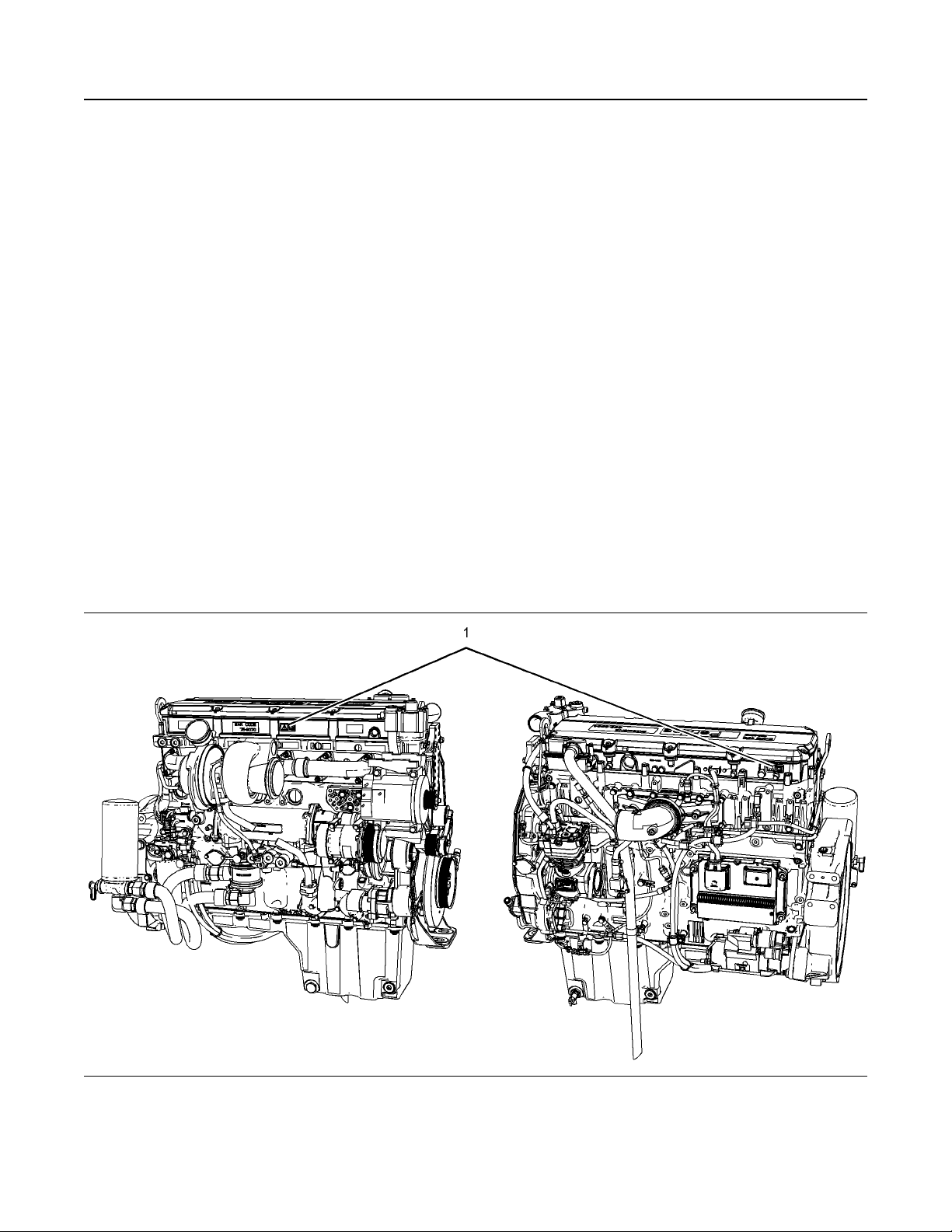
Universal Warning (1)
Illustration 2 g01370904
One safety message is located on the left side of the
engine. One safety message is located on the right
side of the engine.
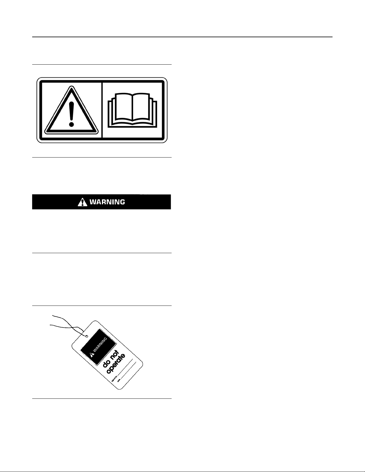
Do not operate or work on this equipment unless
you have read and understand the instructions
and warnings in the Operation and Maintenance
Manuals. Failure to follow the instructions or heed
the warnings could result in serious injury or
death.
Do not allow unauthorized personnel on the engine,
or around the engine when the engine is being
serviced.
• Tampering with the engine installation or tampering
with the OEM supplied wiring can be dangerous.
Personal injury, death and/or engine damage
could result.
• Vent the engine exhaust to the outside when the
engine is operated in an enclosed area.
• If the engine is not running, do not release the
secondary brake or the parking brake systems
unless the vehicle is blocked or unless the vehicle
is restrained.
• Wear a hard hat, protective glasses, and other
protective equipment, as required.
• When work is performed around an engine that is
operating, wear protective devices for ears in order
to help prevent damage to hearing.
• Do not wear loose clothing or jewelry that can snag
on controls or on other parts of the engine.
• Ensure that all protective guards and all covers are
secured in place on the engine.
• Never put maintenance fluids into glass
containers. Glass containers can break.
• Use all cleaning solutions with care.
i06106934
General Hazard Information
Illustration 3 g00104545
Attach a “Do Not Operate” warning tag or a similar
warning tag to the start switch or to the controls
before the engine is serviced or before the engine is
repaired. Attach the warning tags to the engine and to
each operator control station. When appropriate,
disconnect the starting controls.
• Report all necessary repairs.
Unless other instructions are provided, perform the
maintenance under the following conditions:
Page 7
SEBU9072
7
Safety Section
General Hazard Information
• The engine is stopped. Ensure that the engine
cannot be started.
• The protective locks or the controls are in the
applied position.
• Engage the secondary brakes or parking brakes.
• Block the vehicle or restrain the vehicle before
maintenance or repairs are performed.
• Disconnect the batteries when maintenance is
performed or when the electrical system is
serviced. Disconnect the battery ground leads.
Tape the leads in order to help prevent sparks. If
equipped, allow the diesel exhaust fluid to be
purged before disconnecting the battery.
• If equipped, disconnect the connectors for the unit
injectors that are located on the valve cover base.
This action will help prevent personal injury from
the high voltage to the unit injectors. Do not come
in contact with the unit injector terminals while the
engine is operating.
• Do not attempt any repairs or any adjustments to
the engine while the engine is operating.
• Filler caps
• Grease fittings
• Pressure taps
• Breathers
• Drain plugs
Use caution when cover plates are removed.
Gradually loosen, but do not remove the last two bolts
or nuts that are located at opposite ends of the cover
plate or the device. Before removing the last two bolts
or nuts, pry the cover loose in order to relieve any
spring pressure or other pressure.
• Do not attempt any repairs that are not
understood. Use the proper tools. Replace any
equipment that is damaged or repair the
equipment.
• For initial start-up of a new engine or for starting an
engine that has been serviced, make provisions to
stop the engine if an overspeed occurs. The
stopping of the engine may be accomplished by
shutting off the fuel supply and/or the air supply to
the engine. Ensure that only the fuel supply line is
shut off. Ensure that the fuel return line is open.
• Start the engine from the operators station (cab).
Never short across the starting motor terminals or
the batteries. This action could bypass the engine
neutral start system and/or the electrical system
could be damaged.
Engine exhaust contains products of combustion
which may be harmful to your health. Always start the
engine and operate the engine in a well ventilated
area. If the engine is in an enclosed area, vent the
engine exhaust to the outside.
Cautiously remove the following parts. To help
prevent spraying or splashing of pressurized fluids,
hold a rag over the part that is being removed.
Illustration 4 g00702020
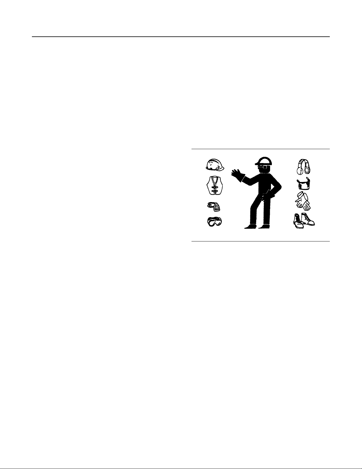
• Wear a hard hat, protective glasses, and other
protective equipment, as required.
• When work is performed around an engine that is
operating, wear protective devices for ears in order
to help prevent damage to hearing.
• Do not wear loose clothing or jewelry that can snag
on controls or on other parts of the engine.
• Ensure that all protective guards and all covers are
secured in place on the engine.
• Never put maintenance fluids into glass
containers. Glass containers can break.
• Use all cleaning solutions with care.
• Report all necessary repairs.
Unless other instructions are provided, perform
the maintenance under the following conditions:
Page 8
8 SEBU9072
Safety Section
General Hazard Information
• The engine is stopped. Ensure that the engine
cannot be started.
• Disconnect the batteries when maintenance is
performed or when the electrical system is
serviced. Disconnect the battery ground leads.
Tape the leads in order to help prevent sparks.
• Do not attempt any repairs that are not
understood. Use the proper tools. Replace any
equipment that is damaged or repair the
equipment.
Pressurized Air and Water
Pressurized air and/or water can cause debris and/or
hot water to be blown out. This action could result in
personal injury.
When pressurized air and/or pressurized water is
used for cleaning, wear protective clothing, protective
shoes, and eye protection. Eye protection includes
goggles or a protective face shield.
The maximum air pressure for cleaning purposes
must be below 205 kPa (30 psi). The maximum water
pressure for cleaning purposes must be below
275 kPa (40 psi).
Fluid Penetration
Pressure can be trapped in the hydraulic circuit long
after the engine has been stopped. The pressure can
cause hydraulic fluid or items such as pipe plugs to
escape rapidly if the pressure is not relieved correctly.
Do not remove any hydraulic components or parts
until pressure has been relieved or personal injury
may occur. Do not disassemble any hydraulic
components or parts until pressure has been relieved
or personal injury may occur. Refer to the OEM
information for any procedures that are required to
relieve the hydraulic pressure.
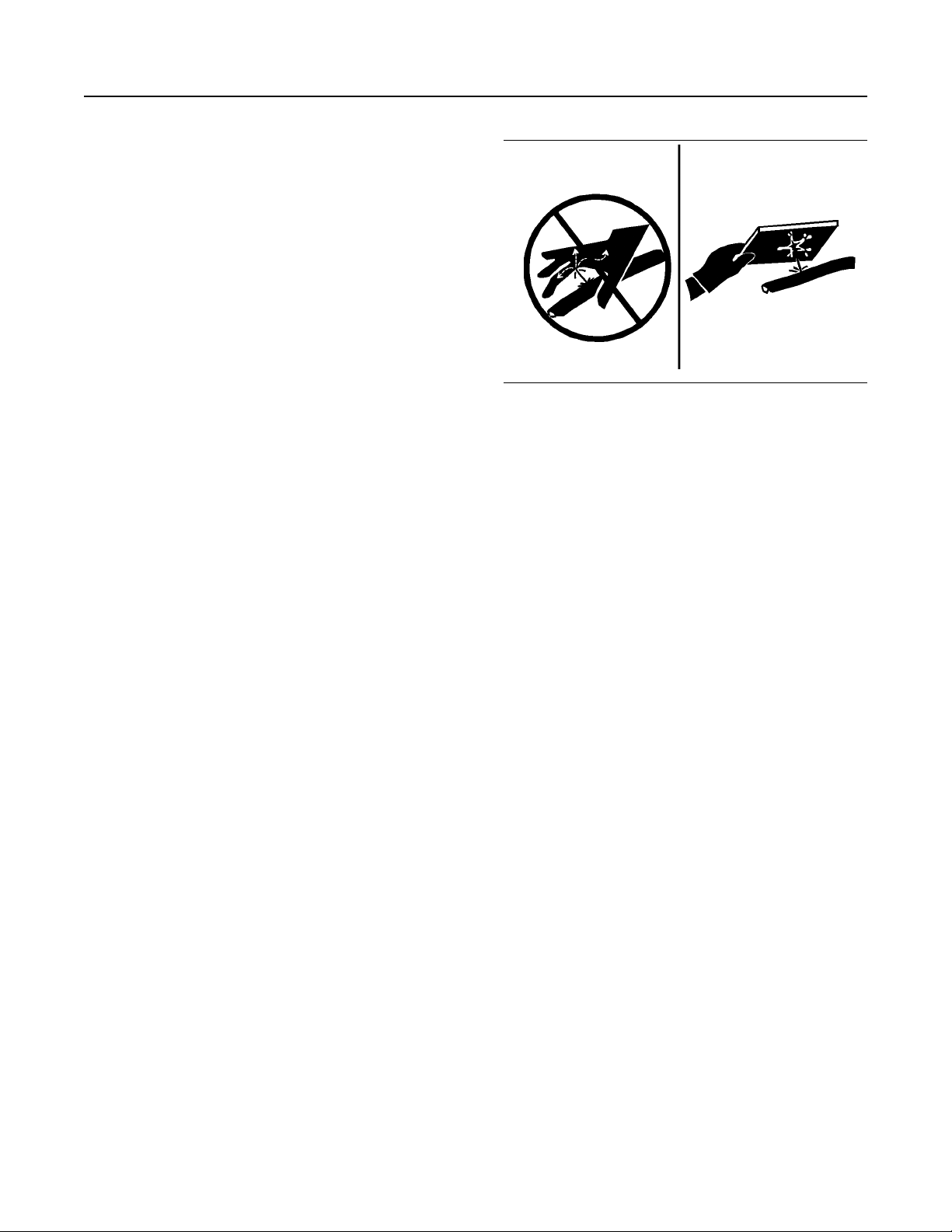
Illustration 5 g00687600
Always use a board or cardboard when you check for
a leak. Leaking fluid that is under pressure can
penetrate body tissue. Fluid penetration can cause
serious injury and possible death. A pin hole leak can
cause severe injury. If fluid is injected into your skin,
you must get treatment immediately. Seek treatment
from a doctor that is familiar with this type of injury.
Containing Fluid Spillage
Care must be taken to ensure that fluids are
contained during performance of inspection,
maintenance, testing, adjusting, and repair of the
product. Be prepared to collect the fluid with suitable
containers before opening any compartment or
disassembling any component containing fluids.
Dispose of all fluids according to local regulations and
mandates.
Static Electricity Hazard when
Fueling with Ultra-low Sulfur Diesel
Fuel
The removal of sulfur and other compounds in ultralow sulfur diesel fuel (ULSD fuel) decreases the
conductivity of ULSD and increases the ability of
ULSD to store static charge. Refineries may have
treated the fuel with a static dissipating additive.
Many factors can reduce the effectiveness of the
additive over time. Static charges can build up in
ULSD fuel while the fuel is flowing through fuel
delivery systems. Static electricity discharge when
combustible vapors are present could result in a fire
or explosion. Ensure that the entire system used to
refuel your machine (fuel supply tank, transfer pump,
transfer hose, nozzle, and others) is properly
grounded and bonded. Consult with your fuel or fuel
system supplier to ensure that the delivery system
complies with fueling standards for proper grounding
and bonding.
Page 9
SEBU9072 9
Safety Section
General Hazard Information
• Never use compressed air for cleaning.
Avoid static electricity risk when fueling. Ultra-low
sulfur diesel fuel (ULSD fuel) poses a greater static ignition hazard than earlier diesel formulations
with a higher sulfur contents. Avoid death or serious injury from fire or explosion. Consult with
your fuel or fuel system supplier to ensure the delivery system is in compliance with fueling standards for proper grounding and bonding practices.
Inhalation
• Avoid brushing materials that contain asbestos.
• Avoid grinding materials that contain asbestos.
• Use a wet method in order to clean up asbestos
materials.
• A vacuum cleaner that is equipped with a high
efficiency particulate air filter (HEPA) can also be
used.
• Use exhaust ventilation on permanent machining
jobs.
• Wear an approved respirator if there is no other
way to control the dust.
• Comply with applicable rules and regulations for
the work place. In the United States, use
Occupational Safety and Health Administration
(OSHA) requirements. These OSHA requirements
can be found in “29 CFR 1910.1001”.
• Obey environmental regulations for the disposal of
asbestos.
• Stay away from areas that might have asbestos
particles in the air.
Illustration 6 g00702022
Exhaust
Use caution. Exhaust fumes can be hazardous to
health. If you operate the equipment in an enclosed
area, adequate ventilation is necessary.
Asbestos Information
Perkins equipment and replacement parts that are
shipped from Perkins engine company limited are
asbestos free. Perkins recommends the use of only
genuine Perkins replacement parts. Use the following
guidelines when you handle any replacement parts
that contain asbestos or when you handle asbestos
debris.
Use caution. Avoid inhaling dust that might be
generated when you handle components that contain
asbestos fibers. Inhaling this dust can be hazardous
to your health. The components that may contain
asbestos fibers are brake pads, brake bands, lining
material, clutch plates, and some gaskets. The
asbestos that is used in these components is usually
bound in a resin or sealed in some way. Normal
handling is not hazardous unless airborne dust that
contains asbestos is generated.
Dispose of Waste Properly
Illustration 7 g00706404
Improperly disposing of waste can threaten the
environment. Potentially harmful fluids should be
disposed of according to local regulations.
Always use leakproof containers when you drain
fluids. Do not pour waste onto the ground, down a
drain, or into any source of water.
If dust that may contain asbestos is present, there are
several guidelines that should be followed:
Page 10
10 SEBU9072
Safety Section
Burn Prevention
i06106969
Burn Prevention
Coolant
When the engine is at operating temperature, the
engine coolant is hot. The coolant is also under
pressure. The radiator and all lines to the heaters or
to the engine contain hot coolant. Any contact with
hot coolant or with steam can cause severe burns.
Allow cooling system components to cool before the
cooling system is drained.
Check that the coolant level after the engine has
stopped and the engine has been allowed to cool.
Ensure that the filler cap is cool before removing the
filler cap. The filler cap must be cool enough to touch
with a bare hand. Remove the filler cap slowly in
order to relieve pressure.
Cooling system conditioner contains alkali. Alkali can
cause personal injury. Do not allow alkali to contact
the skin, the eyes, or the mouth.
Oils
Skin may be irritated following repeated or prolonged
exposure to mineral and synthetic base oils. Refer to
your suppliers Material Safety Data Sheets for
detailed information. Hot oil and lubricating
components can cause personal injury. Do not allow
hot oil to contact the skin. Appropriate personal
protective equipment should be used.
Diesel Fuel
Diesel may be irritating to the eyes, respiratory
system, and skin. Prolonged exposure to diesel may
cause various skin conditions. Appropriate personal
protective equipment should be used. Refer to
supplier Material safety Data sheets for detailed
information.
Batteries
i05945996
Fire Prevention and Explosion
Prevention
Illustration 8 g00704000
All fuels, most lubricants, and some coolant mixtures
are flammable.
Flammable fluids that are leaking or spilled onto hot
surfaces or onto electrical components can cause a
fire. Fire may cause personal injury and property
damage.
After the emergency stop button is operated, ensure
that you allow 15 minutes, before the engine covers
are removed.
Determine whether the engine will be operated in an
environment that allows combustible gases to be
drawn into the air inlet system. These gases could
cause the engine to overspeed. Personal injury,
property damage, or engine damage could result.
If the application involves the presence of
combustible gases, consult your Perkins dealer and/
or your Perkins distributor for additional information
about suitable protection devices.
The liquid in a battery is an electrolyte. Electrolyte is
an acid that can cause personal injury. Do not allow
electrolyte to contact the skin or the eyes.
Do not smoke while checking the battery electrolyte
levels. Batteries give off flammable fumes which can
explode.
Always wear protective glasses when you work with
batteries. Wash hands after touching batteries. The
use of gloves is recommended.
Remove all flammable combustible materials or
conductive materials such as fuel, oil, and debris from
the engine. Do not allow any flammable combustible
materials or conductive materials to accumulate on
the engine.
Store fuels and lubricants in correctly marked
containers away from unauthorized persons. Store
oily rags and any flammable materials in protective
containers. Do not smoke in areas that are used for
storing flammable materials.
Do not expose the engine to any flame.
Exhaust shields (if equipped) protect hot exhaust
components from oil or fuel spray in case of a line, a
tube, or a seal failure. Exhaust shields must be
installed correctly.
Page 11
SEBU9072 11
Safety Section
Fire Prevention and Explosion Prevention
Do not weld on lines or tanks that contain flammable
fluids. Do not flame cut lines or tanks that contain
flammable fluid. Clean any such lines or tanks
thoroughly with a nonflammable solvent prior to
welding or flame cutting.
Wiring must be kept in good condition. Ensure that all
electrical wires are correctly installed and securely
attached. Check all electrical wires daily. Repair any
wires that are loose or frayed before you operate the
engine. Clean all electrical connections and tighten all
electrical connections.
Eliminate all wiring that is unattached or unnecessary.
Do not use any wires or cables that are smaller than
the recommended gauge. Do not bypass any fuses
and/or circuit breakers.
Arcing or sparking could cause a fire. Secure
connections, recommended wiring, and correctly
maintained battery cables will help to prevent arcing
or sparking.
Ensure that the engine is stopped. Inspect all lines
and hoses for wear or for deterioration. Ensure that
the hoses are correctly routed. The lines and hoses
must have adequate support and secure clamps.
Oil filters and fuel filters must be installed correctly.
The filter housings must be tightened to the correct
torque. Refer to the Disassembly and Assembly
manual for more information.
Avoid static electricity risk when fueling. Ultra-low
Sulfur Diesel fuel (ULSD fuel) poses a greater static
ignition hazard than earlier diesel formulations with a
higher sulfur content. Avoid death or serious injury
from fire or explosion. Consult your fuel or fuel system
supplier to ensure that the delivery system is in
compliance with fueling standards for proper
grounding and bonding practices.
Illustration 10 g00704135
Illustration 9 g00704059
Use caution when you are refueling an engine. Do not
smoke while you are refueling an engine. Do not
refuel an engine near open flames or sparks. Always
stop the engine before refueling.
Gases from a battery can explode. Keep any open
flames or sparks away from the top of a battery. Do
not smoke in battery charging areas.
Never check the battery charge by placing a metal
object across the terminal posts. Use a voltmeter or a
hydrometer.
Incorrect jumper cable connections can cause an
explosion that can result in injury. Refer to the
Operation Section of this manual for specific
instructions.
Do not charge a frozen battery. A frozen battery may
cause an explosion.
The batteries must be kept clean. The covers (if
equipped) must be kept on the cells. Use the
recommended cables, connections, and battery box
covers when the engine is operated.
Fire Extinguisher
Make sure that a fire extinguisher is available. Be
familiar with the operation of the fire extinguisher.
Inspect the fire extinguisher and service the fire
extinguisher regularly. Obey the recommendations on
the instruction plate.
Ether
Ether is flammable and poisonous.
Page 12
12 SEBU9072
Safety Section
Crushing Prevention and Cutting Prevention
Do not smoke while you are replacing an ether
cylinder or while you are using an ether spray.
Do not store ether cylinders in living areas or in the
engine compartment. Do not store ether cylinders in
direct sunlight or in temperatures above 49° C
(120° F). Keep ether cylinders away from open
flames or sparks.
Lines, Tubes, and Hoses
Do not bend high-pressure lines. Do not strike highpressure lines. Do not install any lines that are
damaged.
Leaks can cause fires. Consult your Perkins dealer or
your Perkins distributor for replacement parts.
Replace the parts if any of the following conditions
are present:
• End fittings are damaged or leaking.
• Outer coverings are chafed or cut.
• Wires are exposed.
• Outer coverings are ballooning.
• Flexible parts of the hoses are kinked.
Chips or other debris may fly off objects when objects
are struck. Before objects are struck, ensure that no
one will be injured by flying debris.
i05875651
Mounting and Dismounting
Do not climb on the engine. The engine has not been
designed with mounting or dismounting locations.
Refer to the OEM for the location of foot and hand
holds for your specific application.
i04257031
Before Starting Engine
NOTICE
For initial start-up of a new or rebuilt engine, and for
start-up of an engine that has been serviced, make
provision to shut the engine off should an overspeed
occur. This may be accomplished by shutting off the
air and/or fuel supply to the engine.
• Outer covers have embedded armoring.
• End fittings are displaced.
Make sure that all clamps, guards, and heat shields
are installed correctly. During engine operation,
correct installation will help to prevent vibration,
rubbing against other parts, and excessive heat.
i02143194
Crushing Prevention and
Cutting Prevention
Support the component correctly when work beneath
the component is performed.
Unless other maintenance instructions are provided,
never attempt adjustments while the engine is
running.
Stay clear of all rotating parts and of all moving parts.
Leave the guards in place until maintenance is
performed. After the maintenance is performed,
reinstall the guards.
Keep objects away from moving fan blades. The fan
blades will throw objects or cut objects.
Engine exhaust contains products of combustion
which may be harmful to your health. Always start
and operate the engine in a well ventilated area
and, if in an enclosed area, vent the exhaust to the
outside.
Inspect the engine for potential hazards.
Do not start the engine or move any of the controls if
there is a “DO NOT OPERATE” warning tag or
similar warning tag attached to the start switch or to
the controls.
Before starting the engine, ensure that no one is on,
underneath, or close to the engine. Ensure that the
area is free of personnel.
If equipped, ensure that the lighting system for the
engine is suitable for the conditions. Ensure that all
lights work properly, if equipped.
All protective guards and all protective covers must
be installed if the engine must be started in order to
perform service procedures. To help prevent an
accident that is caused by parts in rotation, work
around the parts carefully.
When objects are struck, wear protective glasses in
order to avoid injury to the eyes.
Do not start an engine when the governor linkage is
disconnected.
Page 13

SEBU9072 13
Safety Section
Engine Starting
Do not bypass the automatic shutoff circuits. Do not
disable the automatic shutoff circuits. The circuits are
provided in order to help prevent personal injury. The
circuits are also provided in order to help prevent
engine damage.
i02583384
Engine Starting
Do not use aerosol types of starting aids such as
ether. Such use could result in an explosion and
personal injury.
If a warning tag is attached to the engine start switch
or to the controls DO NOT start the engine or move
the controls. Consult with the person that attached
the warning tag before the engine is started.
All protective guards and all protective covers must
be installed if the engine must be started in order to
perform service procedures. To help prevent an
accident that is caused by parts in rotation, work
around the parts carefully.
Start the engine from the operator's compartment or
from the engine start switch.
i01462046
Engine Stopping
Stop the engine according to the procedure in the
Operation and Maintenance Manual, “Engine
Stopping (Operation Section)” in order to avoid
overheating of the engine and accelerated wear of
the engine components.
Use the Emergency Stop Button (if equipped) ONLY
in an emergency situation. Do not use the Emergency
Stop Button for normal engine stopping. After an
emergency stop, DO NOT start the engine until the
problem that caused the emergency stop has been
corrected.
Stop the engine if an overspeed condition occurs
during the initial start-up of a new engine or an engine
that has been overhauled. This may be accomplished
by shutting off the fuel supply to the engine and/or
shutting off the air supply to the engine.
To stop an electronically controlled engine, cut the
power to the engine.
i06088340
Electrical System
Always start the engine according to the procedure
that is described in the Operation and Maintenance
Manual, “Engine Starting” topic in the Operation
Section. Knowing the correct procedure will help to
prevent major damage to the engine components.
Knowing the procedure will also help to prevent
personal injury.
To ensure that the jacket water heater (if equipped) is
working correctly, check the water temperature gauge
and/or the oil temperature gauge during the heater
operation.
Engine exhaust contains products of combustion
which can be harmful to your health. Always start the
engine and operate the engine in a well ventilated
area. If the engine is started in an enclosed area, vent
the engine exhaust to the outside.
Note: The engine may be equipped with a device for
cold starting. If the engine will be operated in very
cold conditions, then an extra cold starting aid may be
required. Normally, the engine will be equipped with
the correct type of starting aid for your region of
operation.
Never disconnect any charging unit circuit or battery
circuit cable from the battery when the charging unit is
operating. A spark can cause the combustible gases
that are produced by some batteries to ignite.
To help prevent sparks from igniting combustible
gases that are produced by some batteries, the
negative “−” jump-start cable should be connected
last from the external power source to the negative
“−” terminal of the starting motor. If the starting motor
is not equipped with a negative “−” terminal, connect
the jump-start cable to the engine block.
Check the electrical wires daily for wires that are
loose or frayed. Tighten all loose electrical wires
before the engine is started. Repair all frayed
electrical wires before the engine is started. Refer to
the “Engine Starting” section of this Operation and
Maintenance Manual for specific starting instructions.
Grounding Practices
Proper grounding for the engine electrical system is
necessary for optimum engine performance and
reliability. Improper grounding will result in
uncontrolled electrical circuit paths and in unreliable
electrical circuit paths.
Uncontrolled electrical circuit paths can result in
damage to main bearings, to crankshaft bearing
journal surfaces, and to aluminum components.
Page 14
14 SEBU9072
Safety Section
Engine Electronics
Engines that are installed without engine-to-frame
ground straps can be damaged by electrical
discharge.
To ensure that the engine and the engine electrical
systems function properly, an engine-to-frame ground
strap with a direct path to the battery must be used.
This path may be provided by way of a starting motor
ground, a starting motor ground to the frame, or a
direct engine ground to the frame.
All grounds should be tight and free of corrosion. The
engine alternator must be grounded to the negative
“-” battery terminal with a wire that is adequate to
handle the full charging current of the alternator.
i06091234
Engine Electronics
Tampering with the electronic system installation
or the OEM wiring installation can be dangerous
and could result in personal injury or death and/or
engine damage.
The Engine Monitoring package can vary for different
engine models and different engine applications.
However, the monitoring system and the engine
monitoring control will be similar for all engines.
Note: Many of the engine control systems and
display modules that are available for Perkins
Engines will work in unison with the Engine
Monitoring System. Together, the two controls will
provide the engine monitoring function for the specific
engine application. Refer to the Troubleshooting
Manual for more information.
This engine has a comprehensive, programmable
Engine Monitoring System. The Engine Control
Module (ECM) will monitor the engine operating
conditions. If any of the engine parameters extend
outside an allowable range, the ECM will initiate an
immediate action.
The following actions are available for engine
monitoring control: WARNING, DERATE and
SHUTDOWN. These engine monitoring modes can
limit engine speed and/or the engine power.
Many of the parameters that are monitored by the
ECM can be programmed for the engine monitoring
functions. The following parameters can be monitored
as a part of the Engine Monitoring System:
• Operating Altitude
• Engine Coolant Level
• Engine Coolant Temperature
• Engine Oil Pressure
• Engine Speed
• Fuel Temperature
• Intake Manifold Air Temperature
• System Voltage
Page 15
SEBU9072 15
Product Information Section
Model View Illustrations
Product Information
Section
General Information
i06107001
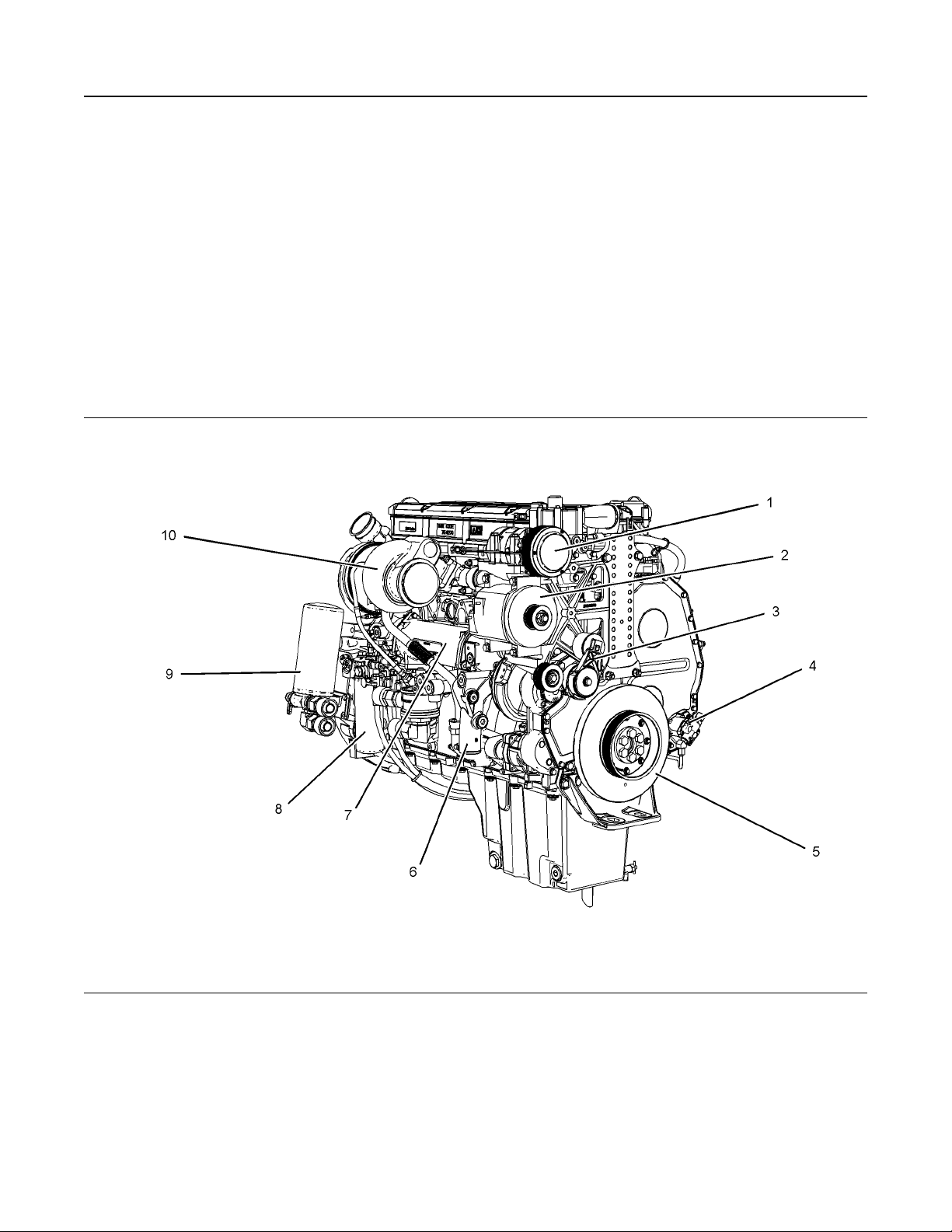
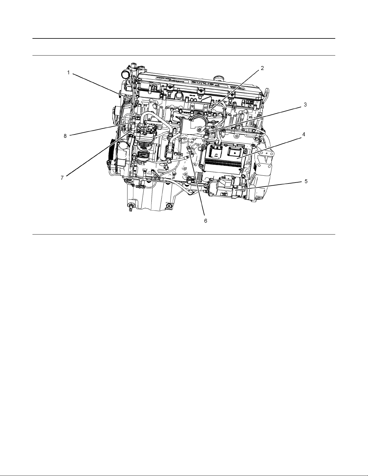
Model View Illustrations
The following model views show typical features of
the engine. Due to individual applications, your
engine may appear different from the illustrations.
Illustration 11 g03812155
(1) Refrigerant compressor
(2) Alternator
(3) Belt tensioner
(4) Fuel transfer pump
(5) Crankshaft damper
(6) Coolant intake
(7) Oil cooler
(8) Secondary fuel filter
(9) Engine oil filter
(10) Turbocharger
Page 16
16 SEBU9072
General Information
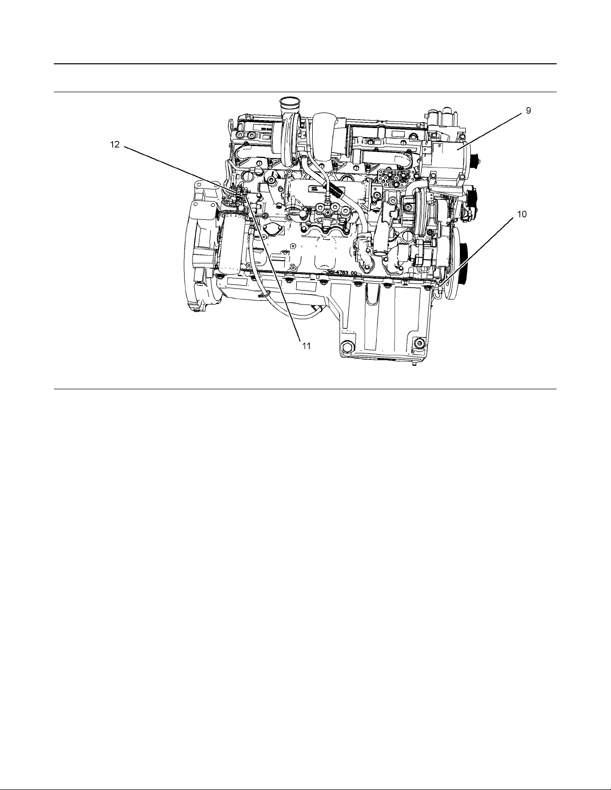
Product Description
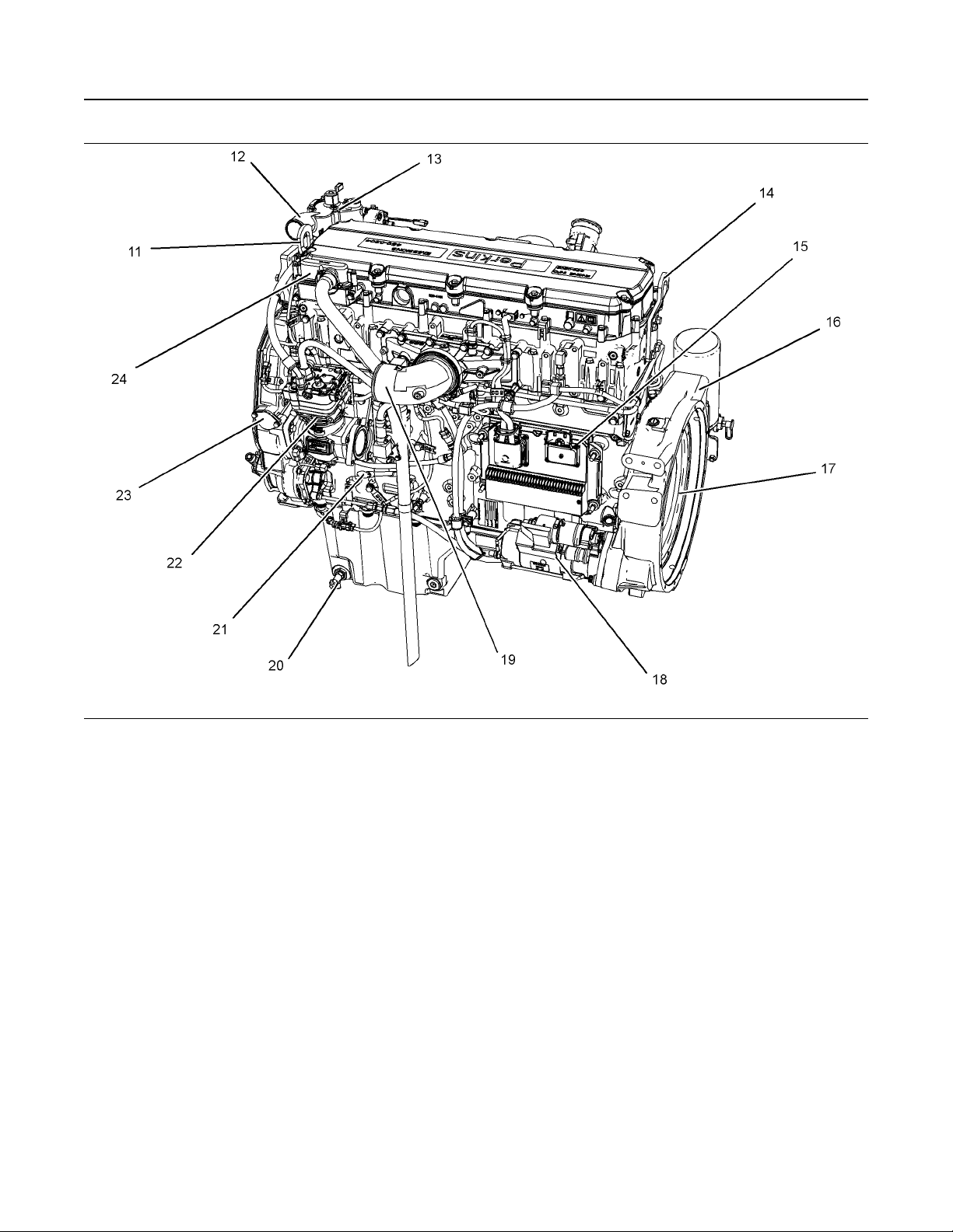
Illustration 12 g03812156
(11) Engine front lifting eye
(12) Coolant outlet
(13) Water temperature regulator housing
(14) Engine rear lifting eye
(15) Electronic control module
Product Description
(16) Flywheel housing
(17) Flywheel
(18) Starting motor
(19) Air intake
(20) Oil drain valve
i06109638
(21) Oil gauge (dipstick)
(22) Air compressor
(23) Location for oil filler
(24) Engine crankcase breather
Engine Specifications
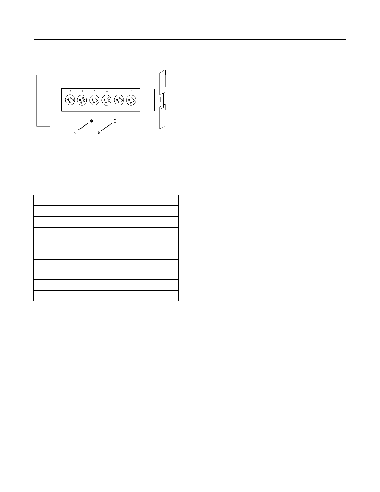
Note: The front end of the engine is opposite the
flywheel end of the engine. The left and the right
sides of the engine are determined from the flywheel
The Perkins 2206D-E13TA Industrial Engine have
end. The number 1 cylinder is the front cylinder.
the following characteristics:
• Four-stroke cycle
• Mechanically actuated, electronically controlled
fuel injection system
• Turbocharged
• Air to air charged cooled
Page 17
SEBU9072 17
General Information
Product Description
Additional Features
The following additional features provide increased
engine fuel economy and serviceability:
• Cold starting capability
• Tampering detection
• Diagnostics
Engine Service Life
Engine efficiency and maximum utilization of engine
performance depend on the adherence to proper
operation and maintenance recommendations. In
Illustration 13 g01387009
Cylinder and valve location
(A) Exhaust valve
(B) Inlet valve
Table 1
Engine Specifications
addition, use recommended fuels, coolants, and
lubricants. Use the Operation and Maintenance
Manual as a guide for required engine maintenance.
Expected engine life is predicted by the average
power that is demanded. The average power that is
demanded is based on fuel consumption of the
engine over a time. Reduced hours of operation at full
throttle and/or operating at reduced throttle settings
Engine
Arrangement and Cylinders In-Line 6 cylinder
Bore 130 mm (5.1 inch)
Stroke 157 mm (6.2 inch)
Aspiration
2206D
ATAAC
result in a lower average power demand. Reduced
hours of operation will increase the length of
operating time before an engine overhaul is required.
For more information, refer to the Operation and
Maintenance Manual, “Overhaul Considerations”
topic.
(1)
Aftermarket Products and Perkins
Engines
Displacement 12.5 L (763 cubic inch)
Firing Order
Rotation (flywheel end)
(1)
Air-to-air aftercooled
1-5-3-6-2-4
Counterclockwise
Electronic Engine Features
Perkins does not warrant the quality or performance
of non-Perkins fluids and filters.
When auxiliary devices, accessories, or consumables
(filters, additives, catalysts, ) which are made by other
manufacturers are used on Perkins products, the
Perkins warranty is not affected simply because of
such use.
The engine is designed for electronic controls. The
integral on board computer controls the operation of
the engine. Current operating conditions are
monitored. The Electronic Control Module (ECM)
controls the response of the engine to these
conditions and to the demands of the operator. These
conditions and operator demands determine the
precise control of fuel injection by the ECM. The
electronic engine control system provides the
following features:
• Engine speed governor
• Automatic air/fuel ratio control
• Torque rise shaping
• Injection timing control
• System diagnostics
However, failures that result from the installation
or use of other manufacturers devices,
accessories, or consumables are NOT Perkins
defects. Therefore, the defects are NOT covered
under the Perkins warranty.
Page 18
18 SEBU9072
Product Identification Information
Plate Locations and Film Locations
Product Identification
Information
i06109784
Plate Locations and Film
Locations
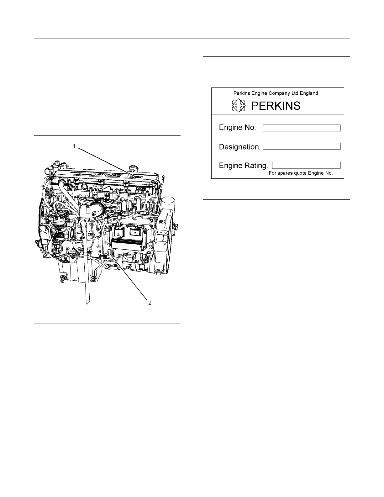
Illustration 14 g03812733
Typical example
(1) Information plate
(2) Serial number plate
The engine serial number plate is located on the left
side of the engine block.
Illustration 15 g01403841
Serial number plate
The following information is stamped on the serial
number plate: engine serial number, engine model
and arrangement number.
The engine information plate is located on top of the
valve cover near the middle of the engine.
The following information is on the information plate:
engine serial number, engine model, engine
arrangement number, maximum altitude of the engine
that is necessary to achieve the rated power,
horsepower, high idle, full load rpm, fuel settings and
other information
i05951816
Emissions Certification Film
Note: This information is pertinent in the United
States, in Canada and in Europe.
The emissions label is located on the top of the valve
mechanism cover.
i06109817
Reference Information
Information for the following items may be needed to
order parts. Locate the information for your engine.
Record the information in the appropriate space.
Make a copy of this list for a record. Keep the
information for future reference.
Page 19

SEBU9072 19
Product Identification Information
Reference Information
Record for Reference
Engine Model
Engine Serial number
Engine Low Idle rpm
Engine Full Load rpm
Primary Fuel Filter Element
Secondary Fuel Filters
Lubrication Oil Filter
Breather Fume Filter Element
Auxiliary Oil Filter
Total Lubrication System Capacity
Total Cooling System Capacity
Air Cleaner Element
Drive Belt
Page 20
20 SEBU9072
Operation Section
Product Lifting
Operation Section
Lifting and Storage
i06109876
Product Lifting
NOTICE
Never bend the eyebolts and the brackets. Only load
the eyebolts and the brackets under tension. Remember that the capacity of an eyebolt is less as the angle
between the supporting members and the object becomes less than 90 degrees.
When it is necessary to remove a component at an
angle, only use a link bracket that is properly rated for
the weight.
Read all the information within produce lifting before
any lifting is attempted. Ensure that the correct set of
lifting eyes for the assembly to be lifted have been
selected.
Use a hoist to remove heavy components. Use an
adjustable lifting beam to lift the assembly. All
supporting members (chains and cables) should be
parallel to each other. The chains and cables should
be perpendicular to the top of the object that is being
lifted.
i06109969
Product Storage
Your Perkins distributor can assist in preparing the
engine for extended storage periods.
An engine can be stored for up to 6 months provided
all the recommendation are adhered to.
Engine
1. Clean the engine of any dirt, rust, grease, and oil.
Inspect the exterior. Paint areas that contain paint
damage with a good quality paint.
2. Remove dirt from the air cleaners. Check all seals,
gaskets, and the filter element for damage.
3. Apply lubricant to all points in this Operation and
Maintenance Manual, “Maintenance Interval
Schedule”.
4. Drain the crankcase oil. Replace the crankcase oil
and change the oil filters. For the proper
procedure, refer to this Operation and
Maintenance Manual.
5. Add VCI oil to the crankcase oil. The volume of VCI
oil in the crankcase oil should be 3 to 4 percent.
Note: If the engine crankcase is full, drain enough
engine oil so the mixture can be added.
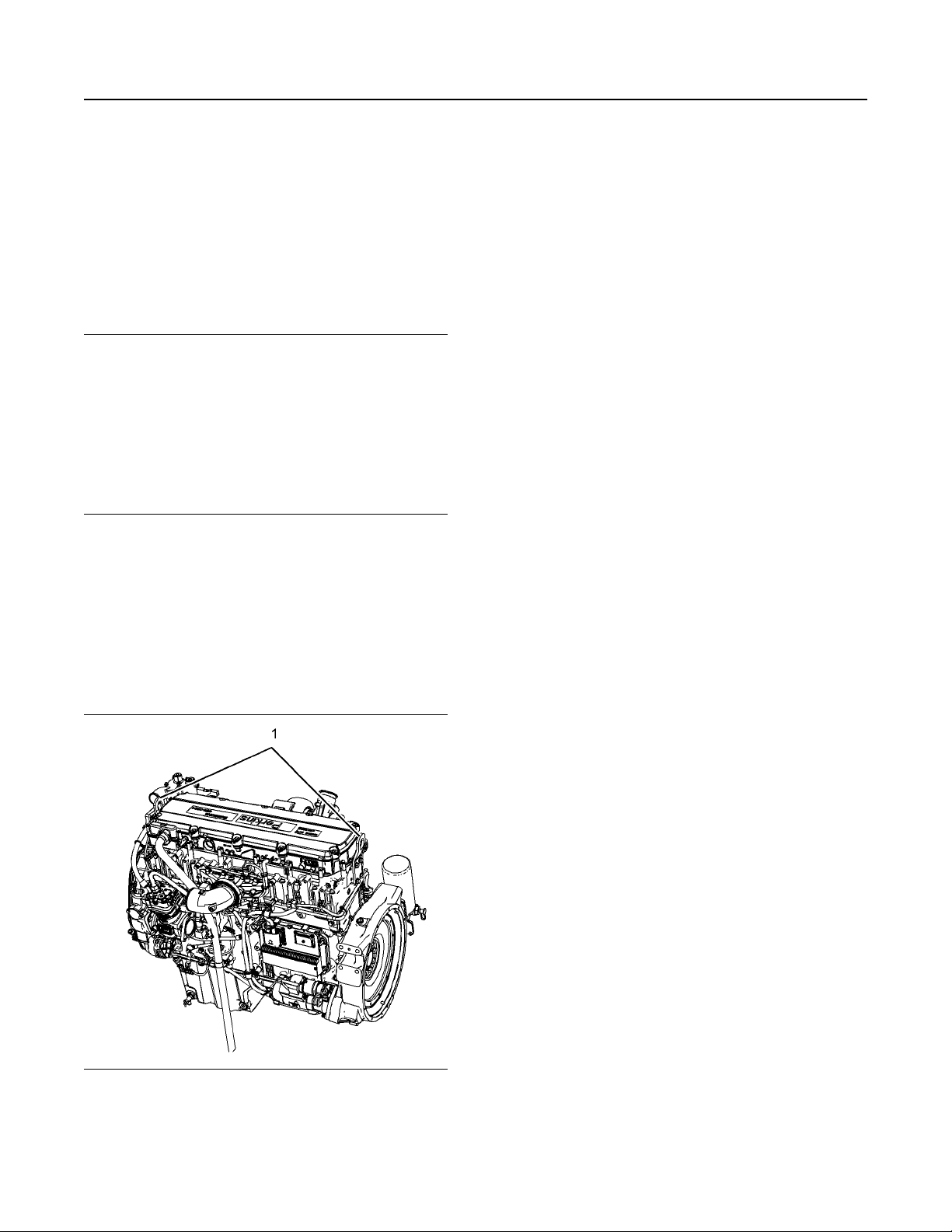
Illustration 16 g03812766
(1) Engine lifting eyes
6. Remove the air filter elements. Turn the engine at
cranking speed with the throttle control in FUEL
OFF position. Use a sprayer to add a mixture of 50
percent VCI oil and 50 percent engine oil into the
air inlet or turbocharger inlet.
Note: The mixture of VCI oil can be added to the inlet
by removing the plug for checking turbocharger boost
pressure. The minimum application rate for the VCI
oil mixture is 5.5 mL per L (3 oz per 1000 cu in) of
engine displacement.
7. Use a sprayer to apply a mixture of 50 percent VCI
oil and 50 percent crankcase oil into the exhaust
openings. The minimum application rate for the oil
mixture is 5.5 mL per L (3 oz per 1000 cu in) of
engine displacement. Seal the exhaust pipe and
seal any drain holes in the muffler.
8. Remove the fuel from the secondary fuel filter
housing. Alternately, empty and reinstall the spinon fuel filter element in order to remove any dirt
and water. Drain any sleeve metering fuel pump.
Page 21

SEBU9072 21
Lifting and Storage
Product Storage
Clean the primary fuel filter. Fill with calibration
fluid or kerosene. Install the primary fuel filter and
operate the priming pump. This procedure will
send clean oil to the secondary filter and the
engine.
Open the fuel tank drain valve in order to drain any
water and dirt from the fuel tank. Apply a spray of
calibration fluid or kerosene at the rate of
30 mL per 30 L (1 oz per 7.50 gal US) of fuel tank
capacity in order to prevent rust in the fuel tank.
Add 0.15 mL per L (.02 oz per 1 gal US) of
commercial biocide such as Biobor JF to the fuel.
Apply a small amount of oil to the threads on the
fuel tank filler neck and install the cap. Seal all
openings to the tank in order to prevent
evaporation of the fuel and as a preservative.
9. Remove the fuel injectors. Apply 30 mL (1 oz) of
the mixture of oils (50 percent VCI oil and 50
percent engine oil) into each cylinder.
Use a bar or a turning tool in order to turn over the
engine slowly. This procedure puts the oil on the
cylinder walls. Install all fuel injectors and tighten to
the correct torque. Refer to Disassembly and
Assembly Manual for more information.
10. Spray a thin amount of a mixture of 50 percent
VCI oil and 50 percent engine oil onto the following
components: flywheel, ring gear teeth and starter
pinion. Install the covers in order to prevent
evaporation of the vapors from the VCI oil.
11. Apply a heavy amount of Multipurpose Grease to
all outside parts that move, such as rod threads,
ball joints, linkage.
Note: Install all covers. Ensure that tape has been
installed over all openings, air inlets, exhaust
openings, the flywheel housing, the crankcase
breathers, the dipstick tubes.
Ensure that all covers are airtight and
weatherproof. Use a waterproof weather resistant
tape such as Kendall No. 231 or an equivalent.
Do not use duct tape. Duct tape will only seal for a
short time.
12. Under most conditions, removing the batteries is
the best procedure. As an alternative, place the
batteries in storage. As needed, periodically
charge the batteries while the batteries are in
storage.
13. Remove the drive belts from the engine
14. Place a waterproof cover over the engine. Ensure
that the engine cover is secure. The cover should
be loose enough to allow air to circulate around the
engine in order to prevent damage from
condensation.
15. Attach a tag with the storage date to the engine.
16. Remove the waterproof cover at 2 month or 3
month intervals in order to check the engine for
corrosion. If the engine has signs of corrosion,
repeat the protection procedure.
Coolant System
Completely fill the cooling system before storage.
Refer to this Operation and Maintenance Manual,
“Fluid Recommendations” for more information about
coolants.
Remove Engine from Storage
1. Remove all outside protective covers.
2. Change the oil and filters.
3. Check the condition of the fan and alternator belts.
Replace the belts, if necessary. Refer to this
Operation and Maintenance Manual, “Belts Inspect/Adjust/Replace” for the correct procedure.
4. Replace the fuel filter elements.
5. Remove the plastic covers from the air cleaner
elements.
6. Use a bar or a turning tool in order to turn the
engine in the normal direction of rotation. The
procedure ensures that no hydraulic locks or
resistance exist.
7. Before starting the engine, remove the valve cover
or covers. Put a large amount of engine oil on the
camshaft, cam followers, and valve mechanism in
order to prevent damage to the mechanism.
If the batteries are not removed, wash the tops of
the batteries until the tops are clean. Apply an
electrical charge to the batteries in order to obtain
a specific gravity of 1.225.
Disconnect the battery terminals. Place a plastic
cover over the batteries.
Page 22
22 SEBU9072
Lifting and Storage
Product Storage
10. Before start-up, test the cooling system for a 3
percent to a 6 percent concentration of coolant
conditioner. Add liquid coolant conditioner or a
coolant conditioner element, if equipped.
Test the coolant mixture for proper nitrite level. If
necessary, adjust the coolant mixture.
Prime the engine with clean diesel fuel before
starting.
11. Ensure that the cooling system is clean. Ensure
that the system is full. Ensure that the system has
the correct amount of supplemental cooling system
conditioner.
12. On the first day of operation, check the entire
engine several times for leaks and correct
operation.
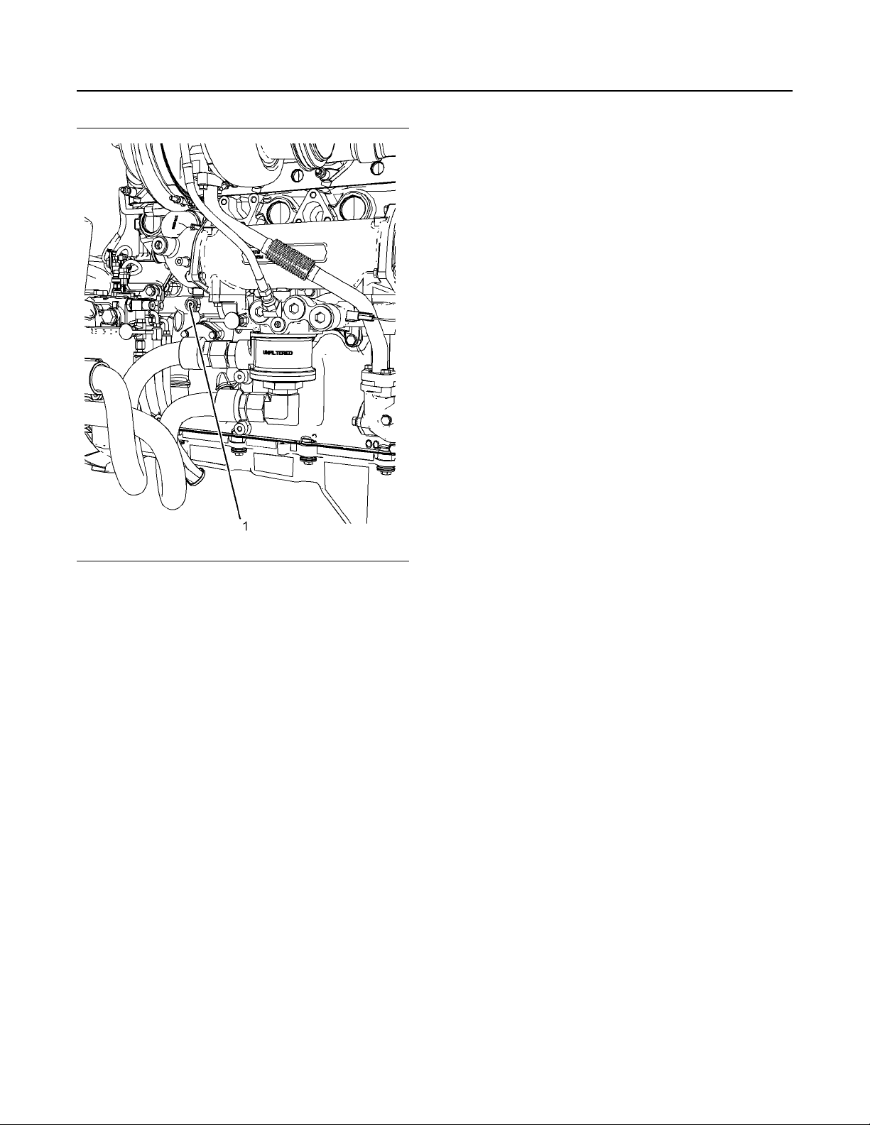
Illustration 17 g03862125
Typical example
(1) plug
8. If an engine is stored for more than 1 year, Perkins
recommends Pre lubrication of the engine in order
to avoid dry starting. Use a suitable pump in order
to put engine oil into the engine oil system.
The pump will need to create a minimum pressure
within the engine of 0.25 bar (3.6 psi). This
pressure is needed for 15 seconds in order to
lubricate the internal surfaces.
Remove of the plug shown in illustration 17 in
order to connect to the engine oil system. The
connection required is 9/16" x 18 tpi. Ensure that
the correct oil specification is used, refer to this
Operation and Maintenance Manual, “Fluid
Recommendations” for more information. After the
engine internal surfaces have been lubricated,
remove connector and install plug (1). Tighten plug
to a torque of 30 N·m (265 lb in). Perkins
recommends that the procedure must be
performed in a minimum ambient temperature of
10° C (50° F).
9. Check the condition of all rubber hoses. Replace
any worn hoses. Replace any damaged hoses.
Page 23
SEBU9072 23
Features and Controls
Battery Disconnect Switch
Features and Controls
i05422613
Battery Disconnect Switch
(If Equipped)
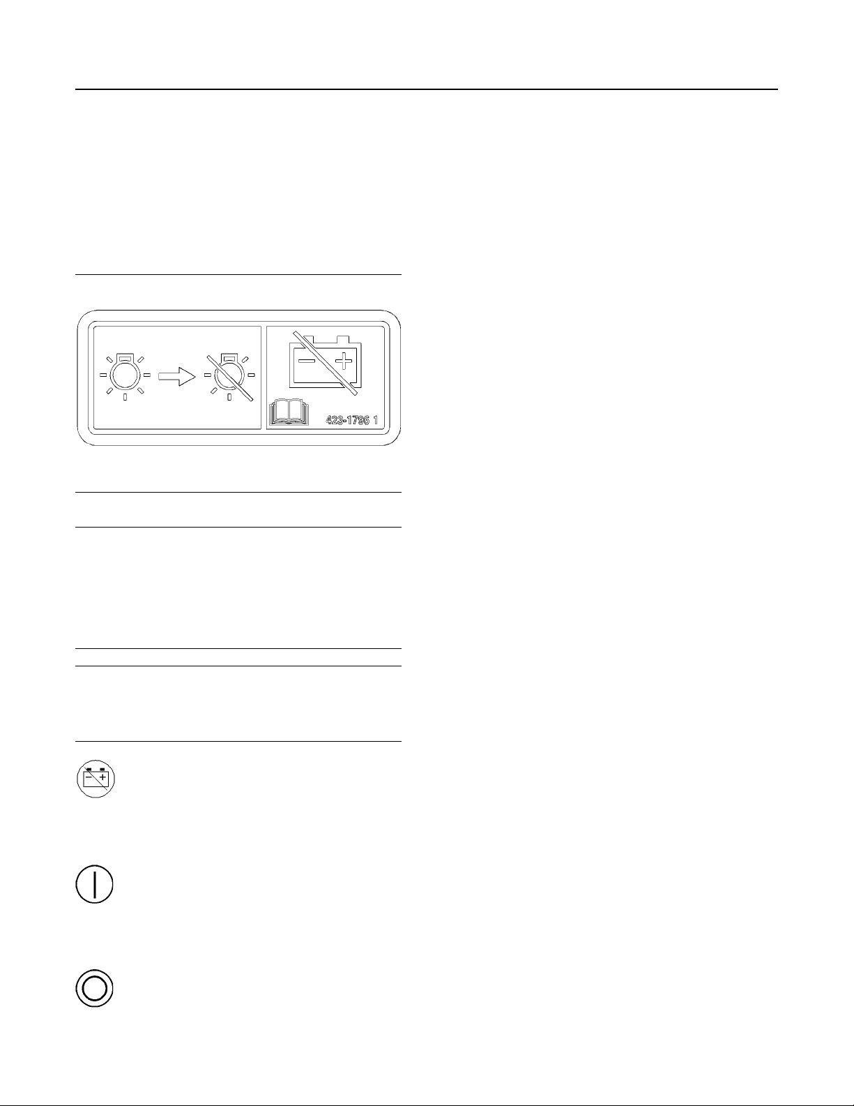
Illustration 18 g03422039
The battery disconnect switch and the engine start
switch perform different functions. The entire
electrical system is disabled when you turn the
battery disconnect switch to the OFF position. The
battery remains connected to the electrical system
when you turn the engine start switch to the OFF
position.
Turn the battery disconnect switch to the OFF
position and remove the key when you service the
electrical system or any other engine components.
Turn the battery disconnect switch to the OFF
position and remove the disconnect switch key after
you operate the engine. This will prevent the battery
from being discharged. The following problems can
cause battery discharge:
• short circuits
• current draw via some components
• vandalism
i06119742
Monitoring System
NOTICE
Do not turn off the battery disconnect switch until the
indicator lamp has turned off. If the switch is turned off
when the indicator lamp is illuminated the Diesel Exhaust Fluid (DEF) system will not purge the DEF. If
the DEF does not purge, DEF could freeze and damage the pump and lines.
NOTICE
Never move the battery disconnect switch to the OFF
position while the engine is operating. Serious damage to the electrical system could result.
Battery Disconnect Switch – The battery
disconnect switch can be used in order
to disconnect the battery from the
engines electrical system. The key must be
inserted into the battery disconnect switch before
the battery disconnect switch can be turned.
ON – To activate the electrical system,
insert the disconnect switch key and
turn the battery disconnect switch
clockwise. The battery disconnect switch must be
turned to the ON position before you start the
engine.
The monitoring system is designed to alert the
operator to an immediate problem.
The engine has protection in three stages:
• Warning
• Action Alert
• Shutdown
The engine protection may be overridden by the
critical condition mode.
The Electronic Control Module (ECM) monitors the
following parameters:
• Engine Temperatures
• Engine Pressures
• Engine Speed
If the parameters exceed a trip point for a period that
is longer than the delay period, the ECM logs an
event code. The indicator switches to the ON
position.
The following parameters are monitored for event
codes:
position.
OFF – To deactivate the electrical
system, turn the battery disconnect
switch counterclockwise to the OFF
Page 24

24 SEBU9072
Features and Controls
Monitoring System
• Lubricating Oil Pressure
• Coolant Temperature
• Overspeed
• Intake Manifold Temperature
• Intake Manifold Pressure
• Fuel Temperature
The temperature protection is disabled for a period
when the engine is cranking in order to compensate
for heat soak solutions.
The ECM has dedicated alarm outputs for each of the
three stages of protection. There are also dedicated
alarm outputs for oil pressure, coolant temperature,
and overspeed events which are energized at any
stage of protection.
Warning Alarm
The Warning alarm informs the user that the engine is
approaching a critical condition.
If the engine is in the Warning condition, then the
event will be logged in the memory of the ECM. An
event code will be transmitted over the Perkins Data
link and the hard wired Warning output will be
energized. If the engine is in the Warning condition,
the event code and output will remain while the
condition exists. The electronic service tool is used to
remove the event code from the memory of the ECM.
The trip point for the Warning alarm will be set to a
factory default in production. The electronic service
tool may be used to alter the trip point for a Warning
within predefined limits.
Action Alert
The Action Alert informs the OEM that the engine is
approaching a critical condition. The engine should
be stopped in a controlled manner. Further running of
the engine may result in an immediate shutdown.
Shutdown
If the engine reaches the Shutdown condition, one of
the following events has occurred: low lubricating oil
pressure, high coolant temperature, or overspeed.
The event will be logged in the memory of the ECM.
The engine will be shut down. An event code will be
transmitted over the Perkins Data link and the hard
wired Shutdown output will be energized. The
Shutdown condition will latch until the ECM is reset.
The event code for the shutdown cannot be cleared
from the memory of the ECM without using a factory
password.
Critical Protection Override
If the engine is in an application that is critical for
safety, the protection system can be overridden in
order to ensure the continuation of the power supply
during engine fault conditions.
Critical Protection Override will be set by a switch
input from the OEM. For example, switch to battery +
in order to disable a critical override. Critical
Protection Override input can be enabled in the
electronic service tool by use of a factory password.
When the Critical Protection Override feature is
active, the ECM will continue to run the engine in all
shutdown conditions except for Overspeed shutdown.
If the shutdown is overridden, an event code is
generated. The ECM will log the event code. The
ECM will energize the following: Warning, Action
Alert, Shutdown, oil pressure, coolant temperature
and overspeed outputs as normal. The warranty of
the engine will be invalidated if the engine is operated
in the following conditions: active event code and
Critical Protection Override mode.
Standard Warning Outputs
The ECM provides individual outputs in order to drive
warning lamps or relays to indicate each of the
following fault conditions:
• Diagnostic Fault
If the engine is in the Action Alert condition, the event
will be logged in the memory of the ECM. An event
code will be transmitted over the Perkins Data link
and the hard wired Action Alert will be energized. If
the engine is in the Action Alert condition, the event
code and output will remain while the condition exists.
The event code cannot be cleared from the memory
of the ECM without using a factory password.
• Oil Pressure
• Coolant Temperature
• Overspeed
• Action Alert
• Warning
• Shutdown
If the ECM detects a warning for the coolant
temperature , the output on the coolant temperature
will be energized and the warning output will be
energized. If the ECM detects a warning for the low
oil pressure, the output on the oil pressure will be
energized and the warning output will be energized.
Page 25

SEBU9072 25
Features and Controls
Sensors and Electrical Components
If the Action Alert alarms are enabled and the ECM
detects a coolant temperature condition, the output
on the coolant Temperature will be energized and the
output on the Action Alert will be energized.
If the engine shuts down on low oil pressure the
output on the low oil pressure will be energized and
the output on the shutdown will be energized. If the
engine shuts down on coolant temperature, or the
engine shuts down on overspeed the dedicated
output and the shutdown output will be energized.
Shutdown Reset
The cause of an engine shutdown must be
investigated. Corrective action must be taken before
the system is reset in order to operate the engine.
After an engine shutdown, operate the reset input of
the ECM or power down the controller.
Powering down the electronic control module can be
achieved by the operation of the keyswitch into sleep
mode. The electronic control module can be powered
down by isolating the power supply to the electronic
control module.
Note: The ECM cannot be reset by using the Reset
input until the engine has stopped.
The Diagnostic output differs from the Warning and
Shutdown outputs. The Warning and Shutdown
outputs refer to the operation of the engine. The
Diagnostic output refers to the condition of the
electronic system and software system.
A diagnostic fault may develop on the lubricating oil
pressure or coolant temperature sensors. For
example, if a Shutdown protection sensor has a fault,
this will result in an engine shutdown, unless the
system is in critical protection override. If a diagnostic
fault occurs, with one of the engine speed sensors
while the engine is running. The engine continues to
run by using the other timing sensor for reference.
i06137289
Sensors and Electrical
Components
The illustrations within the following sections are
typical location of the sensors or electrical
components for an industrial engine. Specific engines
may appear different due to differences in
applications.
Diagnostic
If there is a fault with an engine protection sensor on
the engine, the engine activates a diagnostic code.
The engine communicates the diagnostic code to the
operator via the Diagnostic output. The diagnostic
code provides an indication to the operator of a fault
with the engine protection system. Running of the
engine for a prolonged period in this condition may
result in engine failure. The output is generally used
to drive lamps or relays.
The following sensors are monitored in order to
determine if the sensors are out of the normal range,
an open circuit, or a short circuit:
• Atmosphere Pressure
• Lubricating Oil Pressure
• Inlet Manifold Pressure
• Inlet Manifold Temperature
• Fuel Temperature
• Coolant Temperature
• Engine Speed
• Desired Speed Input
Page 26
26 SEBU9072
Features and Controls
Sensors and Electrical Components
Illustration 19 g03822008
(1) Coolant temperature sensor
(2) Inlet manifold pressure sensor
(3) Inlet air temperature sensor
(4) Electronic control module
(5) Starting motor
(6) Oil pressure sensor
(7) Camshaft speed timing sensor
(8) Barometric pressure sensor
Page 27
SEBU9072 27
Features and Controls
Sensors and Electrical Components
Illustration 20 g03822009
(9) Alternator
(10) Crankshaft speed timing sensor
(11) Fuel temperature sensor
(12) Fuel pressure sensor
Page 28

28 SEBU9072
Engine Diagnostics
Self-Diagnostics
Engine Diagnostics
i05194988
Self-Diagnostics
Perkins Electronic Engines have the capability to
perform a self-diagnostics test. When the system
detects an active problem, a diagnostic lamp is
activated. Diagnostic codes will be stored in
permanent memory in the Electronic Control Module
(ECM). The diagnostic codes can be retrieved by
using Perkins electronic service tools.
Some installations have electronic displays that
provide direct readouts of the engine diagnostic
codes. Refer to the manual that is provided by the
OEM for more information on retrieving engine
diagnostic codes.
Active codes represent problems that currently exist.
These problems should be investigated first.
Logged codes represent the following items:
• Intermittent problems
• Recorded events
• Performance history
The problems may have been repaired since the
logging of the code. These codes do not indicate that
a repair is needed. The codes are guides or signals
when a situation exists. Codes may be helpful to
troubleshoot problems.
When the problems have been corrected, the
corresponding logged fault codes should be cleared.
i03554520
Diagnostic Lamp
A diagnostic lamp is used to indicate the existence of
an active fault. A fault diagnostic code will remain
active until the problem is repaired. The diagnostic
code may be retrieved by using the electronic service
tool.
i01902949
Fault Logging
The system provides the capability of Fault Logging.
When the Electronic Control Module (ECM)
generates an active diagnostic code, the code will be
logged in the memory of the ECM. The codes that
have been logged by the ECM can be identified by
the electronic service tool. The active codes that have
been logged will be cleared when the fault has been
rectified or the fault is no longer active. The following
logged faults can not be cleared from the memory of
the ECM without using a factory password:
Overspeed, low engine oil pressure and high engine
coolant temperature.
i03554534
Engine Operation with Active
Diagnostic Codes
If a diagnostic lamp illuminates during normal engine
operation, the system has identified a situation that is
not within the specification. Use electronic service
tools to check the active diagnostic codes.
Note: If the customer has selected “DERATE” and if
there is a low oil pressure condition, the Electronic
Control Module (ECM) will limit the engine power until
the problem is corrected. If the oil pressure is within
the normal range, the engine may be operated at the
rated speed and load. However, maintenance should
be performed as soon as possible.
The active diagnostic code should be investigated.
The cause of the problem should be corrected as
soon as possible. If the cause of the active diagnostic
code is repaired and there is only one active
diagnostic code, the diagnostic lamp will turn off.
Operation of the engine and performance of the
engine can be limited as a result of the active
diagnostic code that is generated. Acceleration rates
may be significantly slower. Refer to the
Troubleshooting Guide for more information on the
relationship between these active diagnostic codes
and engine performance.
i06225055
Configuration Parameters
The engine electronic control module (ECM) has two
types of configuration parameters. The system
configuration parameters and the customer specified
parameters.
Page 29

SEBU9072 29
Engine Diagnostics
Engine Operation with Intermittent Diagnostic Codes
The electronic service tool is required in order to alter
the configuration parameters.
System Configuration Parameters
System configuration parameters affect the emissions
of the engine or the power of the engine. System
configuration parameters are programmed at the
factory. Normally, system configuration parameters
would never require changing through the life of the
engine. System configuration parameters must be
reprogrammed if an ECM is replaced. System
configuration parameters do not require
reprogrammed if the ECM software is changed.
Factory passwords are required to change these
parameters.
For more information on system configuration
parameters and customer specified parameters, refer
to Troubleshooting manual.
i01797063
Engine Operation with
Intermittent Diagnostic Codes
If a diagnostic lamp illuminates during normal engine
operation and the diagnostic lamp shuts off, an
intermittent fault may have occurred. If a fault has
occurred, the fault will be logged into the memory of
the Electronic Control Module (ECM).
In most cases, it is not necessary to stop the engine
because of an intermittent code. However, the
operator should retrieve the logged fault codes and
the operator should reference the appropriate
information in order to identify the nature of the event.
The operator should log any observation that could
have caused the lamp to light.
• Low power
• Limits of the engine speed
• Excessive smoke, etc
This information can be useful to help troubleshoot
the situation. The information can also be used for
future reference. For more information on diagnostic
codes, refer to the Troubleshooting Guide for this
engine.
Page 30

30 SEBU9072
Engine Starting
Before Starting Engine
Engine Starting
i02109067
Before Starting Engine
Perform the required daily maintenance and other
periodic maintenance before the engine is started.
Inspect the engine compartment. This inspection can
help prevent major repairs at a later date. Refer to the
Operation and Maintenance Manual, “Maintenance
Interval Schedule” for more information.
• For the maximum service life of the engine, make
a thorough inspection before the engine is started.
Look for the following items: oil leaks, coolant
leaks, loose bolts and trash buildup. Remove trash
buildup and arrange for repairs, as needed.
• Inspect the aftercooler for loose connections and
for debris buildup.
• Inspect the cooling system hoses for cracks and
for loose clamps.
• Inspect the alternator and accessory drive belts for
cracks, breaks, and other damage.
• Inspect the wiring for loose connections and for
worn wires or frayed wires.
• Check the fuel supply. Drain water from the water
separator (if equipped). Open the fuel supply
valve.
• Do not start the engine or move any of the controls
if there is a “DO NOT OPERATE” warning tag or
similar warning tag attached to the start switch or
to the controls.
• Ensure that the areas around the rotating parts are
clear.
• All of the guards must be put in place. Check for
damaged guards or for missing guards. Repair any
damaged guards. Replace damaged guards and/
or missing guards.
• Disconnect any battery chargers that are not
protected against the high current drain that is
created when the electric starting motor (if
equipped) is engaged. Check electrical cables and
check the battery for poor connections and for
corrosion.
• Reset all of the shutoffs or alarm components.
• Check the engine lubrication oil level. Maintain the
oil level between the “ADD” mark and the “FULL”
mark on the oil level gauge.
• Check the coolant level. Observe the coolant level
in the coolant recovery tank (if equipped). Maintain
the coolant level to the “FULL” mark on the
coolant recovery tank.
• If the engine is not equipped with a coolant
recovery tank maintain the coolant level within
13 mm (0.5 inch) of the bottom of the filler pipe. If
the engine is equipped with a sight glass, maintain
the coolant level in the sight glass.
NOTICE
All valves in the fuel return line must be open before
and during engine operation to help prevent high fuel
pressure. High fuel pressure may cause filter housing
failure or other damage.
If the engine has not been started for several weeks,
fuel may have drained from the fuel system. Air may
have entered the filter housing. Also, when fuel filters
have been changed, some air pockets will be trapped
in the engine. In these instances, prime the fuel
system. Refer to the Operation and Maintenance
Manual, “Fuel System - Prime” for more information
on priming the fuel system.
Engine exhaust contains products of combustion
which may be harmful to your health. Always start
and operate the engine in a well ventilated area
and, if in an enclosed area, vent the exhaust to the
outside.
• Observe the air cleaner service indicator (if
equipped). Service the air cleaner when the yellow
diaphragm enters the red zone, or when the red
piston locks in the visible position.
• Ensure that any driven equipment has been
disengaged. Minimize electrical loads or remove
any electrical loads.
i04132731
Cold Weather Starting
Startability will be improved at temperatures below
10°C (50°F) from the use of a cylinder block coolant
heater or from other means that are used to heat the
crankcase oil. Some engine applications use a jacket
water heater to improve startability. Use of a jacket
water heater will help reduce white smoke and misfire
during start-up in cold weather.
Page 31
SEBU9072 31
Engine Starting
Starting the Engine
Note: If the engine has not been run for several
weeks, fuel may have drained. Air may have moved
into the filter housing. Also, when fuel filters have
been changed, some air will be left in the filter
housing. Refer to the Operation and Maintenance
Manual, “Fuel System - Prime” (Maintenance
Section) for more information on priming the fuel
system.
Ether Injection System (If
Equipped)
The ether injection system is controlled by the ECM.
The ECM monitors the coolant temperature, intake air
temperature, ambient air temperature, and barometric
pressure to determine when ether injection is needed.
At sea level, ether will be used if any of the
temperatures fails to exceed 0° C (32° F). This
temperature is subject to an increase as barometric
pressure increases.
Personal injury or property damage can result
from alcohol or starting fluids.
Alcohol or starting fluids are highly flammable
and toxic and if improperly stored could result in
injury or property damage.
Follow the procedure in this Operation and
Maintenance Manual, “Starting the Engine”.
i06092648
Starting the
Engine
During the key on, all warning lamps will illuminate
for a few seconds, in order to test the circuits. If
any lamps do not illuminate, check the bulbs and
replace as necessary.
NOTICE
Do not engage the starting motor when flywheel is
turning. Do not start the engine under load.
If the engine fails to start within 30 seconds, release
the starter switch or button and wait two minutes to al-
low the starting motor to cool before attempting to
start the engine again.
3. Push the start button or turn the ignition switch to
the START position in order to crank the engine.
Do not push down or hold the throttle down while
the engine is cranked. The system will
automatically provide the correct amount of fuel
that is needed to start the engine.
4. If the engine fails to start within 30 seconds,
release the start button, or the ignition switch. Wait
for 2 minutes in order to allow the starting motor to
cool before attempting to start the engine again.
NOTICE
Oil pressure should rise within 15 seconds after the
engine starts. Do not increase engine rpm until the oil
pressure gauge indicates normal. If oil pressure is not
indicated on the gauge within 15 seconds, DO NOT
operate the engine. STOP the engine, investigate
and correct the cause.
5. Allow the engine to idle for approximately 3
minutes. Idle the engine until the water
temperature gauge has begun to rise. Check all
gauges during the warm-up period.
Engine exhaust contains products of combustion
which may be harmful to your health. Always start
and operate the engine in a well ventilated area
and, if in an enclosed area, vent the exhaust to the
outside.
Starting the Engine
Refer to the Owners Manual of the OEM for your type
of controls. Use the following procedure to start the
engine.
1. Place the transmission in NEUTRAL. Disengage
the flywheel clutch in order to allow the engine to
start faster, and to reduce the draining of the
battery.
2. Turn the ignition switch to the ON position.
Note: Oil pressures and fuel pressures should be in
the normal range on the instrument panel. Engines
that are equipped with “WARNING” lamps do not
have an operating range. The “WARNING and
DIAGNOSTIC” lamp (if equipped) will flash while the
engine is cranking. The lamp should turn off after
proper engine oil pressure or fuel pressure is
achieved. Do not apply a load to the engine or
increase engine rpm until the oil pressure gauge
indicates at least normal pressure. Inspect the engine
for leaks and/or unusual noises.
Page 32

32 SEBU9072
Engine Starting
Starting with Jump Start Cables
If the engine is operated with a low load, the engine
will reach normal operating temperature sooner than
idling the engine with no load. When the engine is
idled in cold weather, increase the engine rpm to
approximately 1000 to 1200 rpm in order to raise
engine temperature. Do not exceed the
recommended rpm in order to increase the speed of
the warm-up. Limit unnecessary idle time to 10
minutes.
Starting Problems
An occasional starting problem may be caused by
one of the following items:
• Low battery charge
• Lack of fuel
• Problem with the wiring harness
If the engine fuel system has been run dry, fill the fuel
tank and prime the fuel system. Refer to the
Operation and Maintenance Manual, “Fuel System Prime” topic (Maintenance Section).
If the other problems are suspected, perform the
appropriate procedure in order to start the engine.
Problems with the Wiring Harness
2. If a wire is loose, push the wire back into the
connector. Pull the wire again in order to ensure
that the wire is secure.
3. Start the engine. If the engine does not start, check
for a diagnostic code and consult your Perkins
distributor.
i06092747
Starting with Jump Start
Cables
(Do Not Use This Procedure in
Hazardous Locations that have
Explosive Atmospheres)
The connection of battery cables to a battery and
the disconnection of battery cables from a battery
may cause an explosion which may result in injury or death. The connection and the disconnection of other electrical equipment may also cause
an explosion which may result in injury or death.
The procedures for the connection and the disconnection of battery cables and other electrical
equipment should only be performed in a nonexplosive atmosphere.
Illustration 21 g01248812
ECM Connector J2/P2
Locate the ECM. Check the connector in order to
ensure that the connector is secure. Lightly pull each
of the wires in the chassis harness.
1. Pull each wire with approximately 4.5 kg (10 lb) of
force. The wire should remain in the connector.
Improper jump start cable connections can cause
an explosion resulting in personal injury.
Prevent sparks near the batteries. Sparks could
cause vapors to explode. Do not allow jump start
cable ends to contact each other or the engine.
Note: If possible, first diagnose the reason for the
starting failure. Refer to Troubleshooting, “Engine Will
Not Crank and Engine Cranks But Will Not Start” for
further information. Make any necessary repairs. If
the engine will not start only due to the condition of
the battery, either charge the battery, or start the
engine by using another battery with jump-start
cables.
The condition of the battery can be rechecked after
the engine has been switched OFF.
Page 33

SEBU9072 33
Engine Starting
After Starting Engine
NOTICE
Using a battery source with the same voltage as the
electric starting motor. Use ONLY equal voltage for
jump starting. The use of higher voltage will damage
the electrical system.
Do not reverse the battery cables. The alternator can
be damaged. Attach ground cable last and remove
first.
Turn all electrical accessories OFF before attaching
the jump start cables.
Ensure that the main power switch is in the OFF position before attaching the jump start cables to the engine being started.
1. Turn the start switch on the stalled engine to the
OFF position. Turn off all the engines accessories.
2. Connect one positive end of the jump-start cable to
the positive cable terminal of the discharged
battery. Connect the other positive end of the jumpstart cable to the positive cable terminal of the
electrical source.
3. Connect one negative end of the jump-start cable
to the negative cable terminal of the electrical
source. Connect the other negative end of the
jump-start cable to the engine block or to the
chassis ground. This procedure helps to prevent
potential sparks from igniting the combustible
gases that are produced by some batteries.
Note: The engine ECM must be powered before the
starting motor is operated or damage can occur.
4. Start the engine in the normal operating procedure.
Refer to this Operation and Maintenance Manual,
“Starting the Engine”.
5. Immediately after the engine is started, disconnect
the jump-start cables in reverse order.
After jump starting, the alternator may not be able to
recharge fully batteries that are severely discharged.
The batteries must be replaced or charged to the
proper voltage with a battery charger after the engine
is stopped. Many batteries which are considered
unusable are still rechargeable. Refer to Operation
and Maintenance Manual, “Battery - Replace” and
Testing and Adjusting Manual, “Battery - Test”.
i05359363
After Starting Engine
Note: In temperatures from 0 to 60°C (32 to 140°F),
the warm-up time is approximately 3 minutes. In
temperatures below 0°C (32°F), additional warm-up
time may be required.
When the engine is idling during warm-up, observe
the following conditions:
• Check for fluid or air leaks at idle rpm and at onehalf full rpm (no load on the engine) before
operating the engine under load. Operating the
engine at idle and at one-half full rpm with no load
is not possible in some applications.
• Operate the engine at low idle until all systems
achieve operating temperatures. Check all gauges
during the warm-up period.
Note: Gauge readings should be observed and the
data should be recorded frequently while the engine
is operating. Comparing the data over time will help to
determine normal readings for each gauge.
Comparing data over time will also help detect
abnormal operating developments. Significant
changes in the readings should be investigated.
Extended Idle at Cold Ambient
Temperature
The engine may automatically change speeds when
the engine is idling in cold ambient temperatures
(typically less than 0° C (32° F) for extended periods.
The purpose of the automatic speed change is
threefold: to maintain the desired operation of the
NOx reduction system, to maintain the desired
operation of the regeneration system and to keep the
engine coolant warm. The engine speed may rise to
1600 rpm for as long as 20 minutes.
The high exhaust system temperature lamp may
illuminate during extended idling conditions. This
illumination signals that a diesel particulate filter
(DPF) regeneration is in progress. Regenerations
during cold ambient extended idling may only last up
to 10 minutes.
Page 34

34 SEBU9072
Engine Operation
Engine Operation
Engine Operation
i06219260
Engine Operation
Correct operation and maintenance are key factors in
obtaining the maximum life and economy of the
engine. If the directions in the Operation and
Maintenance Manual are followed, costs can be
minimized and engine service life can be maximized.
Variable Speed Engine
The engine can be operated at the rated rpm after the
engine reaches operating temperature. The engine
will reach normal operating temperature sooner
during a low engine speed (rpm) and during a lowpower demand. This procedure is more effective than
idling the engine at no load. The engine should reach
operating temperature in a few minutes.
Gauge readings should be observed and the data
should be recorded frequently while the engine is
operating. Comparing the data over time will help to
determine normal readings for each gauge.
Comparing data over time will also help detect
abnormal operating developments. Significant
changes in the readings should be investigated.
Interrupted starts put excessive stress on the drive
train. Interrupted starts also waste fuel. To get the
driven equipment in motion, engage the clutch
smoothly with no load on the equipment. This
method should produce a start that is smooth and
easy. The engine rpm should not increase and the
clutch should not slip.
3. Ensure that the ranges of the gauges are normal
when the engine is operating at one-half of the
rated rpm. Ensure that all gauges operate properly.
4. Increase the engine rpm to the rated rpm. Always
increase the engine rpm to the rated rpm before
the load is applied.
5. Apply the load. Begin operating the engine at low
load. Check the gauges and equipment for proper
operation. After normal oil pressure is reached and
the temperature gauge begins to move, the engine
may be operated at full load. Check the gauges
and equipment frequently when the engine is
operated under load.
Extended operation at low idle or at reduced load
may cause increased oil consumption and carbon
buildup in the cylinders. This carbon buildup
results in a loss of power and/or poor performance.
i04018232
Constant Speed Engine
Allow the engine to warn up before applying load.
Gauge readings should be observed and the data
should be recorded frequently while the engine is
operating. Comparing the data over time will help to
determine normal readings for each gauge.
Comparing data over time will also help detect
abnormal operating developments. Significant
changes in the readings should be investigated.
i04038637
Engaging the
Driven
Equipment
1. Operate the engine at one-half of the rated rpm,
when possible.
2. Engage the driven equipment without a load on the
equipment, when possible.
Fuel Conservation Practices
The efficiency of the engine can affect the fuel
economy. Perkins design and technology in
manufacturing provides maximum fuel efficiency in all
applications. Follow the recommended procedures in
order to attain optimum performance for the life of the
engine.
• Avoid spilling fuel.
Fuel expands when the fuel is warmed up. The fuel
may overflow from the fuel tank. Inspect fuel lines for
leaks. Repair the fuel lines, as needed.
• Be aware of the properties of the different fuels.
Use only the recommended fuels. Refer to the
Operations and Maintenance Manual, “Fuel
Recommendations”for further information.
• Avoid unnecessary idling.
Shut off the engine rather than idle for long periods of
time.
Page 35

SEBU9072 35
Engine Operation
Fuel Conservation Practices
• Observe the service indicator frequently. Keep the
air cleaner elements clean.
• Ensure that the turbocharger is operating correctly.
For more information refer to this Operation and
Maintenance Manual, “Turbocharger - Inspect”
• Maintain a good electrical system.
One faulty battery cell will overwork the alternator.
This fault will consume excess power and excess
fuel.
• The belt should be in good condition. Refer to the
Systems Operation, Testing and Adjusting, “V-Belt
Test” for further information.
• Ensure that all of the connections of the hoses are
tight. The connections should not leak.
• Ensure that the driven equipment is in good
working order.
• Cold engines consume excess fuel. Utilize heat
from the jacket water system and the exhaust
system, when possible. Keep cooling system
components clean and keep cooling system
components in good repair. Never operate the
engine without water temperature regulators. All of
these items will help maintain operating
temperatures.
Page 36

36 SEBU9072
Cold Weather Operation
Radiator Restrictions
Cold Weather Operation
i05954317
Radiator Restrictions
Perkins discourages the use of airflow restriction
devices that are mounted in front of radiators. Airflow
restriction can cause the following conditions:
• High exhaust temperatures
• Power loss
• Excessive fan usage
• Reduction in fuel economy
If an airflow restriction device must be used, the
device should have a permanent opening directly in
line with the fan hub. The device must have a
minimum opening dimension of at least 770 cm
(120 in2).
A centered opening that is directly in line with the fan
hub is specified in order to prevent an interrupted
airflow on the fan blades. Interrupted airflow on the
fan blades could cause a fan failure.
Perkins recommends a warning device for the inlet
manifold temperature and/or the installation of an inlet
air temperature gauge. The warning device for the
inlet manifold temperature should be set at 75 °C
(167 °F). The inlet manifold air temperature should
not exceed 75 °C (167 °F). Temperatures that
exceed this limit can cause power loss and potential
engine damage.
2
i05849931
The cloud point of the fuel is the temperature at which
waxes naturally found in the diesel fuel begin to form
crystals. The cloud point of the fuel must be below
lowest ambient temperature to prevent filters from
plugging.
Cold Filter Plugging Point is a temperature at which a
particular fuel will pass through a standardized
filtration device. This CFPP gives an estimate of the
lower operability temperature of fuel
Pour point is the last temperature before the fuel flow
stops and waxing of the fuel will start.
Be aware of these properties when diesel fuel is
purchased. Consider the average ambient air
temperature for the engines application. Engines that
are fueled in one climate may not operate well if the
engines are shipped to colder climate. Problems can
result due to changes in temperature.
Before troubleshooting for low power or for poor
performance in the winter, check the fuel for waxing
The following components can provide a means of
minimizing fuel waxing problems in cold weather:
• Fuel heaters, which may be an OEM option
• Fuel line insulation, which may be an OEM option
Winter and arctic grades of diesel fuel are available in
the countries and territories with severe winters. For
more information refer to the Operation and
Maintenance Manual, “Fuel For Cold Weather
Operation”
Another important fuel property which can affect cold
start and operation of diesel engine is Cetane
number. Detail and requirements of this property are
given in this Operation and Maintenance Manual,
“Fluid Recommendations”.
Fuel and the
Effect from Cold
Weather
Note: Only use grades of fuel that are recommended
by Perkins. Refer to this Operation and Maintenance
Manual, “Fluid Recommendations”.
Properties of the diesel fuel can have a significant
effect on the engine cold start capability. It is critical
that the low temperature properties of diesel fuel are
acceptable for the minimum ambient temperature the
engine is expected to see in the operation.
Following properties are used to define fuels low
temperature capability:
• Cloud point
• Pour point
• Cold Filter Plugging Point (CFPP)
i06093465
Fuel Related Components in
Cold Weather
Fuel Tanks
Condensation can form in partially filled fuel tanks.
Top off the fuel tanks after operating the engine.
Fuel tanks should contain some provision for draining
water and sediment from the bottom of the tanks.
Some fuel tanks use supply pipes that allow water
and sediment to settle below the end of the fuel
supply pipe.
Some fuel tanks use supply lines that take fuel
directly from the bottom of the tank. If the engine is
equipped with this system, regular maintenance of
the fuel system filter is important.
Page 37

SEBU9072 37
Cold Weather Operation
Fuel Related Components in Cold Weather
Drain the water and sediment from any fuel storage
tank at the following intervals:
• Weekly
• Oil changes
• Refueling of the fuel tank
This draining will help prevent water and/or sediment
from being pumped from the fuel storage tank and
into the engine fuel tank.
Fuel Heaters
Fuel heaters help to prevent fuel filters from plugging
in cold weather due to waxing. A fuel heater should
be installed in order for the fuel to be heated before
the fuel enters the primary fuel filter.
Select a fuel heater that is mechanically simple, yet
adequate for the application. The fuel heater should
also help to prevent overheating of the fuel. High fuel
temperatures reduce engine performance and the
availability of engine power. Choose a fuel heater with
a large heating surface. The fuel heater should be
practical in size. Small heaters can be too hot due to
the limited surface area.
Disconnect the fuel heater in warm weather.
Note: Fuel heaters that are controlled by the water
temperature regulator or self-regulating fuel heaters
should be used with this engine. Fuel heaters that are
not controlled by the water temperature regulator can
heat the fuel in excess of 65° C (149° F). A loss of
engine power can occur if the fuel supply temperature
exceeds 37° C (100° F).
Note: Heat exchanger type fuel heaters should have
a bypass provision in order to prevent overheating of
the fuel in warm-weather operation.
For further information on fuel heaters, consult your
Perkins distributor .
Page 38

38 SEBU9072
Engine Stopping
Stopping the Engine
Engine Stopping
i02334873
Stopping the
Stopping the engine immediately after it has been
working under load, can result in overheating and accelerated wear of the engine components.
Avoid accelerating the engine prior to shutting it
down.
Avoiding hot engine shutdowns will maximize turbocharger shaft and bearing life.
Note: Individual applications will have different
control systems. Ensure that the shutoff procedures
are understood. Use the following general guidelines
in order to stop the engine.
1. Remove the load from the engine. Reduce the
engine speed (rpm) to low idle. Allow the engine to
idle for five minutes in order to cool the engine.
2. Stop the engine after the cool down period
according to the shutoff system on the engine and
turn the ignition key switch to the OFF position. If
necessary, refer to the instructions that are
provided by the OEM.
Manual Stop Procedure
Engine
NOTICE
i05812522
1. Remove the load from the engine so that the
engine has no more than 30% power.
2. Run the engine at the programmed low idle speed
for at least 3 minutes.
3. After the cool down period, turn the start switch to
the OFF position.
i01465494
After Stopping Engine
Note: Before you check the engine oil, do not operate
the engine for at least 10 minutes in order to allow the
engine oil to return to the oil pan.
• Check the crankcase oil level. Maintain the oil level
between the “ADD” mark and the “FULL” mark
on the oil level gauge.
• If necessary, perform minor adjustments. Repair
any leaks and tighten any loose bolts.
• Note the service hour meter reading. Perform the
maintenance that is in the Operation and
Maintenance Manual, “Maintenance Interval
Schedule”.
• Fill the fuel tank in order to help prevent
accumulation of moisture in the fuel. Do not overfill
the fuel tank.
NOTICE
Only use antifreeze/coolant mixtures recommended
in the Coolant Specifications that are in the Operation
and Maintenance Manual. Failure to do so can cause
engine damage.
NOTICE
Stopping the engine immediately after it has been
working under load can result in overheating and accelerated wear of the engine components.
If the engine has been operating at high rpm and/or
high loads, run at low idle for at least three minutes to
reduce and stabilize internal engine temperature before stopping the engine.
Avoiding hot engine shutdowns will maximize turbocharger shaft and bearing life.
Note: Individual applications have different control
systems. Ensure that the shutoff procedures are
understood. Use the following general guidelines in
order to stop the engine.
• Allow the engine to cool. Check the coolant level.
• If freezing temperatures are expected, check the
coolant for proper antifreeze protection. The
cooling system must be protected against freezing
to the lowest expected outside temperature. Add
the proper coolant/water mixture, if necessary.
• Perform all required periodic maintenance on all
driven equipment. This maintenance is outlined in
the instructions from the OEM.
Page 39

SEBU9072 39
Maintenance Section
Refill Capacities
Maintenance Section
Refill Capacities
i06093491
Refill Capacities
Refer to this Operation and Maintenance Manual,
“Fluid Recommendations” for information about the
fluids which are acceptable for this engine.
Lubricant Refill Capacity
Table 2
2206 Industrial Engine
Approximate Refill Capacities
Oil Sump
Standard Oil Pan
Deep Oil Pan
Center Oil Pan
(1)
These values are approximate capacities for the crankcase oil
sump which include the standard oil filters that are installed at
the factory. Engines with auxiliary oil filters will require additional
oil. Refer to the OEM specifications for the capacity of the auxiliary oil filter.
(1)
Liters
32 L
37 L
30 L
Quarts
33.8 qt
39.1 qt
31.7 qt
The refill capacities for the engine crankcase reflect
the approximate capacity of the crankcase or sump
plus standard oil filters. Auxiliary oil filter systems will
require additional oil. Refer to the OEM specifications
for the capacity of the auxiliary oil filter.
Coolant Refill Capacity
To maintain the cooling system, the total cooling
system capacity must be known. The capacity of the
total cooling system will vary. The capacity will
depend on the size of the radiator (capacity). Table 3
should be completed by the customer for the
maintenance of the cooling system.
Table 3
Approximate Capacity of the Cooling System
Illustration 22 g02293575
Standard and deep oil pans
Illustration 23 g02289293
Center oil pan
Compartment or
System
Total Cooling System
(1)
(1)
The total cooling system capacity includes the following components:the engine block, the radiator and all coolant hoses and
lines.
Liters Quarts
i06194716
Fluid Recommendations
General Coolant Information
NOTICE
Never add coolant to an overheated engine. Engine
damage could result. Allow the engine to cool first.
NOTICE
If the engine is to be stored in, or shipped to an area
with below freezing temperatures, the cooling system
must be either protected to the lowest outside temperature or drained completely to prevent damage.
Page 40

40 SEBU9072
Refill Capacities
Fluid Recommendations
NOTICE
Frequently check the specific gravity of the coolant for
proper freeze protection or for anti-boil protection.
Clean the cooling system for the following reasons:
• Contamination of the cooling system
• Overheating of the engine
• Foaming of the coolant
NOTICE
Never operate an engine without water temperature
regulators in the cooling system. Water temperature
regulators help to maintain the engine coolant at the
proper operating temperature. Cooling system problems can develop without water temperature
regulators.
Many engine failures are related to the cooling
system. The following problems are related to cooling
system failures: Overheating, leakage of the water
pump and plugged radiators or heat exchangers.
These failures can be avoided with correct cooling
system maintenance. Cooling system maintenance is
as important as maintenance of the fuel system and
the lubrication system. Quality of the coolant is as
important as the quality of the fuel and the lubricating
oil.
Coolant is normally composed of three elements:
Water, additives and glycol.
Water
Water is used in the cooling system in order to
transfer heat.
Distilled water or deionized water is
recommended for use in engine cooling systems.
DO NOT use the following types of water in cooling
systems: Hard water, softened water that has been
conditioned with salt and sea water.
If distilled water or deionized water is not available,
use water with the properties that are listed in Table 4
.
Table 4
Acceptable Water
For a water analysis, consult one of the following
sources:
• Local water utility company
• Agricultural agent
• Independent laboratory
Additives
Additives help to protect the metal surfaces of the
cooling system. A lack of coolant additives or
insufficient amounts of additives enable the following
conditions to occur:
• Corrosion
• Formation of mineral deposits
• Rust
• Scale
• Foaming of the coolant
Many additives are depleted during engine operation.
These additives must be replaced periodically.
Additives must be added at the correct concentration.
Over concentration of additives can cause the
inhibitors to drop out-of-solution. The deposits can
enable the following problems to occur:
• Formation of gel compounds
• Reduction of heat transfer
• Leakage of the water pump seal
• Plugging of radiators, coolers, and small passages
Glycol
Glycol in the coolant helps to provide protection
against the following conditions:
• Boiling
• Freezing
• Cavitation of the water pump
For optimum performance, Perkins recommends a
1:1 mixture of a water/glycol solution.
Property
Chloride (Cl) 40 mg/L
Sulfate (SO
Total Hardness
Total Solids
Acidity pH of 5.5 to 9.0
) 100 mg/L
4
Maximum Limit
170 mg/L
340 mg/L
Note: Use a mixture that will provide protection
against the lowest ambient temperature.
Note: 100 percent pure glycol will freeze at a
temperature of −13 °C (8.6 °F).
Page 41

SEBU9072 41
Refill Capacities
Fluid Recommendations
Most conventional antifreezes use ethylene glycol.
Propylene glycol may also be used. In a 1:1 mixture
with water, ethylene and propylene glycol provide
similar protection against freezing and boiling. Refer
to Table 5 and refer to table 6 .
Table 5
Ethylene Glycol
Concentration Freeze Protection
50 Percent
60 Percent
−36 °C (−33 °F)
−51 °C (−60 °F)
NOTICE
Do not use propylene glycol in concentrations that exceed 50 percent glycol because of the reduced heat
transfer capability of propylene glycol. Use ethylene
glycol in conditions that require additional protection
against boiling or freezing.
Table 6
Propylene Glycol
Concentration Freeze Protection
50 Percent
−29 °C (−20 °F)
To check the concentration of glycol in the coolant,
measure the specific gravity of the coolant.
Coolant Recommendations
• ELC Extended Life Coolant
• SCA Supplement Coolant Additive
• ASTM American Society for Testing and
Materials
The following two coolants are used in Perkins
diesel engines:
Preferred – Perkins ELC
NOTICE
Do not use a commercial coolant/antifreeze that only
meets the ASTM D3306 specification. This type of
coolant/antifreeze is made for light automotive
applications.
Perkins recommends a 1:1 mixture of water and
glycol. This mixture of water and glycol will provide
optimum heavy-duty performance as an antifreeze.
This ratio may be increased to 1:2 water to glycol if
extra freezing protection is required.
A mixture of SCA inhibitor and water is acceptable
but will not give the same level of corrosion, boiling
and, freezing protection as ELC. Perkins
recommends a 6 percent to 8 percent concentration
of SCA in those cooling systems. Distilled water or
deionized water is preferred. Standard required
ASTM D1384, D2570, and D4340
Table 7
Coolant Service Life
Coolant Type
Perkins ELC
Commercial Heavy-Duty Anti-
freeze that meets “ASTM
Commercial SCA inhibitor and
(1)
Use the interval that occurs first. The cooling system must also
be flushed out at this time.
D6210”
Water
Service Life
6,000 Service Hours or Three
3000 Service Hours or Two Year
3000 Service Hours or One Year
(1)
Years
ELC
Perkins provides ELC for use in the following
applications:
• Heavy-duty spark ignited gas engines
• Heavy-duty diesel engines
• Automotive applications
Acceptable – A commercial heavy-duty antifreeze
that meets “ASTM D6210” specifications
NOTICE
The 1200 and 2200 series industrial engines must
be operated with a 1:1 mixture of water and glycol.
This concentration allows the NOx reduction system to operate correctly at high ambient
temperatures.
The anti-corrosion package for ELC is different from
the anti-corrosion package for other coolants. ELC is
an ethylene glycol base coolant. However, ELC
contains organic corrosion inhibitors and antifoam
agents with low amounts of nitrite. Perkins ELC has
been formulated with the correct amount of these
additives in order to provide superior corrosion
protection for all metals in engine cooling systems.
ELC is available in a premixed cooling solution with
distilled water. ELC is a 1:1 mixture. The Premixed
ELC provides freeze protection to −36 °C (−33 °F).
The Premixed ELC is recommended for the initial fill
of the cooling system. The Premixed ELC is also
recommended for topping off the cooling system.
Containers of several sizes are available. Consult
your Perkins distributor for the part numbers.
Page 42

42 SEBU9072
Refill Capacities
Fluid Recommendations
ELC Cooling System Maintenance
Correct additions to the Extended Life
Coolant
NOTICE
Use only Perkins products for pre-mixed or concentrated coolants.
Mixing Extended Life Coolant with other products reduces the Extended Life Coolant service life. Failure
to follow the recommendations can reduce cooling
system components life unless appropriate corrective
action is performed.
In order to maintain the correct balance between the
antifreeze and the additives, you must maintain the
recommended concentration of ELC. Lowering the
proportion of antifreeze lowers the proportion of
additive. Lowering the ability of the coolant to protect
the system will form pitting, from cavitation, from
erosion, and from deposits.
NOTICE
Do not use a conventional coolant to top-off a cooling
system that is filled with Extended Life Coolant (ELC).
Do not use standard supplemental coolant additive
(SCA).
When using Perkins ELC, do not use standard SCA's
or SCA filters.
ELC Cooling System Cleaning
NOTICE
Care must be taken to ensure that all fluids are contained during performance of inspection, maintenance, testing, adjusting and the repair of the
product. Be prepared to collect the fluid with suitable
containers before opening any compartment or disassembling any component containing fluids.
Dispose of all fluids according to local regulations and
mandates.
1. Drain the coolant into a suitable container.
2. Dispose of the coolant according to local
regulations.
3. Fill the cooling system with a 33 percent solution of
Perkins ELC and operate the engine, ensure that
the thermostat opens. Stop the engine and allow
the engine to cool. Drain the coolant.
Note: Use distilled or deionized water in the solution.
4. Again, fill the cooling system with a 33 percent
solution of Perkins ELC and operate the engine
ensure that the thermostat opens. Stop the engine
and allow to cool.
5. Drain the drain the cooling system.
NOTICE
Incorrect or incomplete flushing of the cooling system
can result in damage to copper and other metal
components.
Note: If the cooling system is already using ELC,
cleaning agents are not required to be used at the
specified coolant change interval. Cleaning agents
are only required if the system has been
contaminated by the addition of some other type of
coolant or by cooling system damage.
Clean water is the only cleaning agent that is required
when ELC is drained from the cooling system.
Before the cooling system is filled, the heater control
(if equipped) must be set to the HOT position. Refer
to the OEM in order to set the heater control. After the
cooling system is drained and the cooling system is
refilled, operate the engine until the coolant level
reaches the normal operating temperature and until
the coolant level stabilizes. As needed, add the
coolant mixture in order to fill the system to the
specified level.
Changing to Perkins ELC
To change from heavy-duty antifreeze to the Perkins
ELC, perform the following steps:
6. Fill the cooling system with the Perkins Premixed
ELC. Operate the engine. Ensure that all coolant
valves open then stop the engine. When cool
check the coolant level.
ELC Cooling System Contamination
NOTICE
Mixing ELC with other products reduces the effectiveness of the ELC and shortens the ELC service life.
Use only Perkins Products for premixed or concentrate coolants. Failure to follow these recommendations can result in shortened cooling system
component life.
ELC cooling systems can withstand contamination to
a maximum of 10 percent of conventional heavy-duty
antifreeze or SCA. If the contamination exceeds 10
percent of the total system capacity, perform ONE of
the following procedures:
Page 43

SEBU9072 43
Refill Capacities
Fluid Recommendations
• Drain the cooling system into a suitable container.
Dispose of the coolant according to local
regulations. Flush the system with a 5 to 10
percent solution of Perkins ELC. Fill the system
with the Perkins ELC.
• Drain a portion of the cooling system into a
suitable container according to local regulations.
Then, fill the cooling system with premixed ELC.
This procedure should lower the contamination to
less than 10 percent.
• Maintain the system as a conventional Heavy-Duty
Coolant. Treat the system with an SCA. Change
the coolant at the interval that is recommended for
the conventional Heavy-Duty Coolant.
Commercial Heavy-Duty Antifreeze and
SCA
NOTICE
Commercial Heavy-Duty Coolant which contains
Amine as part of the corrosion protection system must
not be used.
NOTICE
Never operate an engine without water temperature
regulators in the cooling system. Water temperature
regulators help to maintain the engine coolant at the
correct operating temperature. Cooling system problems can develop without water temperature
regulators.
Table 8
Equation For Adding The SCA To The Heavy-Duty Coolant At
V is the total volume of the cooling system.
X is the amount of SCA that is required.
The Initial Fill
V × 0.045 = X
Table 9 is an example for using the equation that is in
Table 8 .
Table 9
Example Of The Equation For Adding The SCA To The Heavy-
Total Volume of the
Cooling System (V)
15 L (4 US gal) × 0.045 0.7 L (24 oz)
Duty Coolant At The Initial Fill
Multiplication
Factor
that is Required (X)
Amount of SCA
Adding The SCA to The Heavy-Duty
Coolant For Maintenance
Heavy-duty antifreeze of all types REQUIRE periodic
additions of an SCA.
Test the antifreeze periodically for the concentration
of SCA. For the interval, refer to the Operation and
Maintenance Manual, “Maintenance Interval
Schedule” (Maintenance Section). Cooling System
Supplemental Coolant Additive (SCA) Test/Add.
Additions of SCA are based on the results of the test.
The size of the cooling system determines the
amount of SCA that is needed.
Check the antifreeze (glycol concentration) in order to
ensure adequate protection against boiling or
freezing. Perkins recommends the use of a
refractometer for checking the glycol concentration. A
hydrometer should not be used.
Perkins engine cooling systems should be tested at
500 hour intervals for the concentration of SCA.
Additions of SCA are based on the results of the test.
An SCA that is liquid may be needed at 500 hour
intervals.
Adding the SCA to Heavy-Duty Coolant at
the Initial Fill
Use the equation that is in Table 8 to determine the
amount of SCA that is required when the cooling
system is initially filled.
Use the equation that is in Table 10 to determine the
amount of SCA that is required, if necessary:
Table 10
Equation For Adding The SCA To The Heavy-Duty Coolant For
V is the total volume of the cooling system.
X is the amount of SCA that is required.
Maintenance
V × 0.014 = X
Table 11 is an example for using the equation that is
in Table 10 .
Table 11
Example Of The Equation For Adding The SCA To The Heavy-
Total Volume of the
Cooling System (V)
15 L (4 US gal) × 0.014 0.2 L (7 oz)
Duty Coolant For Maintenance
Multiplication
Factor
that is Required (X)
Amount of SCA
Page 44

44
Refill Capacities
Fluid Recommendations
SEBU9072
Cleaning the System of Heavy-Duty
Antifreeze
• Clean the cooling system after used coolant is
drained or before the cooling system is filled with
new coolant.
• Clean the cooling system whenever the coolant is
contaminated or whenever the coolant is foaming.
i06218481
Fluid Recommendations
(Fuel Recommendations)
• Glossary
• ISO International Standards Organization
• ASTM American Society for Testing and Materials
• HFRR High Frequency Reciprocating Rig for
Lubricity testing of diesel fuels
• FAME Fatty Acid Methyl Esters
Table 12 provides a known reliable baseline in order
to judge the expected performance of distillate diesel
fuels that are derived from conventional sources.
Satisfactory engine performance is dependent on the
use of a good quality fuel. The use of a good quality
fuel will give the following results: long engine life and
acceptable exhaust emissions levels. The fuel must
meet the minimum requirements that are stated in
table 12 .
NOTICE
The footnotes are a key part of the Perkins Specification for Distillate Diesel Fuel Table. Read ALL of the
footnotes.
• CFRCo-ordinating Fuel Research
• LSD Low Sulfur Diesel
• ULSD Ultra Low Sulfur Diesel
• RMERape Methyl Ester
• SME Soy Methyl Ester
• EPA Environmental Protection Agency of the
United States
General Information
NOTICE
Every attempt is made to provide accurate, up-to-date
information. By use of this document you agree that
Perkins Engines Company Limited is not responsible
for errors or omissions.
NOTICE
These recommendations are subject to change without notice. Contact your local Perkins distributor for
the most up-to-date recommendations.
Diesel Fuel Requirements
Perkins is not in a position to evaluate continuously
and monitor all worldwide distillate diesel fuel
specifications that are published by governments and
technological societies.
Page 45

SEBU9072
Fluid Recommendations
Table 12
Perkins Specification for Distillate Diesel Fuel
Property UNITS Requirements “ASTM Test” “ISO Test”
Aromatics %Volume 35% maximum “D1319” “ISO 3837”
Ash %Weight 0.01% maximum “D482” “ISO 6245”
45
Refill Capacities
Carbon Residue on 10%
%Weight 0.35% maximum “D524” “ISO 4262”
Bottoms
Cetane Number
(1)
Cloud Point °C The cloud point must not ex-
-
40 minimum “D613 or D6890” “ISO 5165”
“D2500” “ISO 3015”
ceed the lowest expected
ambient temperature.
Copper Strip Corrosion
Distillation °C 10% at 282 °C (539.6 °F)
-
No. 3 maximum “D130” “ISO 2160”
“D86” “ISO 3405”
maximum
90% at 360 °C (680 °F)
maximum
Density at 15 °C (59 °F)
(2)
Kg / M
3
800 minimum and 860
No equivalent test “ISO 3675” or “ISO 12185”
maximum
Flash Point °C legal limit “D93” “ISO 2719”
Thermal Stability
-
Minimum of 80% reflectance
“D6468” No equivalent test
after aging for 180 minutes
at 150 °C (302 °F)
Pour Point °C 6 °C (10°F)
“D97” “ISO 3016”
Minimum below ambient
temperature
Sulfur %mass
Kinematic Viscosity
(4)
“MM2/S (cSt)” The viscosity of the fuel that
(3)
“D5453 or /D26222” “ISO 20846” or “ISO 20884”
“D445” “ISO 3405”
is delivered to the fuel injection pump. “1.4 minimum
and /4.5 maximum”
Water and sediment % weight 0.05% maximum “D1796” “ISO 3734”
Water % weight 0.05% maximum “D1744” No equivalent test
Sediment % weight 0.05% maximum “D473” “ISO 3735”
Gums and Resins
Lubricity corrected wear
(5)
mg/100mL 10 mg per 100 mL maximum “D381” “ISO 6246”
mm
0.46 maximum “D6079” “ISO 12156-1”
scar diameter at 60 °C
(140 °F).
Fuel cleanliness
(1)
(2)
(6)
(7)
-
“ISO”18/16/13 “7619” “ISO 4406”
In order to insure minimum cetane number of 40 a distillate diesel fuel should have minimum cetane index of 44 when ASTM D4737 test method is used. A fuel with a higher cetane number is recommended in order to operate at a higher altitude or in cold weather.
Density range allowed includes summer and winter diesel fuel grades. Fuel density varies depending on the sulfur level where high sulfur fuels
have higher densities. Some unblended alternative fuels have lower densities which are acceptable, if all the other properties meet this
specification.
(3)
Regional regulations, national regulations, or international regulations can require a fuel with a specific sulfur limit. Consult all applicable regulations before selecting a fuel for a given engine application. LSD fuel with less than 0.05 percent (≤ 500 ppm (mg/kg)) sulfur is strongly recommended for use in these engine models. Diesel fuel with more than 0.05 percent (≥ 500 ppm (mg/kg)) sulphur can be used only where allowed
by legislation. Fuel sulfur levels affect exhaust emissions. High sulfur fuels also increase the potential for corrosion of internal components.
Fuel sulfur levels above 0.05% may significantly shorten the oil change interval. For additional information, refer to General lubricant
Information.
(continued)
Page 46

46 SEBU9072
Refill Capacities
Fluid Recommendations
(Table 12, contd)
(4)
The values of the fuel viscosity are the values as the fuel is delivered to the fuel injection pumps. Fuel should also meet the minimum viscosity
requirement and the fuel should meet the maximum viscosity requirements at 40° C (104° F) of either the "ASTM D445" test method or the
"ISO 3104" test method. If a fuel with a low viscosity is used, cooling of the fuel may be required to maintain 1.4 cSt or greater viscosity at the
fuel injection pump. Fuels with a high viscosity might require fuel heaters in order to lower the viscosity to 4.5 cSt at the fuel injection pump.
(5)
Follow the test conditions and procedures for gasoline (motor).
(6)
The lubricity of a fuel is a concern with low sulfur and ultra low sulfur fuel. To determine the lubricity of the fuel, use the “ISO 12156-1 or ASTM
D6079 High Frequency Reciprocating Rig (HFRR)” test. If the lubricity of a fuel does not meet the minimum requirements, consult your fuel
supplier. Do not treat the fuel without consulting the fuel supplier. Some additives are not compatible. These additives can cause problems in
the fuel system.
(7)
Recommended cleanliness level for fuel as dispensed into machine or engine fuel tank is "ISO 18/16/13 or cleaner as per ISO 4406. Refer to
the "Contamination Control Recommendations for Fuels" in this chapter.
NOTICE
Operating with fuels that do not meet the Perkins recommendations can cause the following effects: Starting difficulty, poor combustion, deposits in the fuel
injectors, reduced service life of the fuel system, deposits in the combustion chamber and reduced service life of the engine.
Engines that are manufactured by Perkins are certified with the fuel that is prescribed by the United
States Environmental Protection Agency. Engines
that are manufactured by Perkins are certified with
the fuel that is prescribed by the European Certification and other regulatory agencies. Perkins does not
certify diesel engines on any other fuel.
Note: The owner and the operator of the engine has
the responsibility of using the fuel that is prescribed
by the Environmental Protection Agency (EPA) and
other appropriate regulatory agencies.
Diesel Fuel Characteristics
Perkins Recommendations
Cetane Number
Fuel that has a high cetane number will give a shorter
ignition delay. A high cetane number will produce a
better ignition quality. Cetane numbers are derived for
fuels against proportions of cetane and
heptamethylnonane in the standard CFR engine.
Refer to “ISO 5165” for the test method.
Viscosity
Viscosity is the property of a liquid of offering
resistance to shear or flow. Viscosity decreases with
increasing temperature. This decrease in viscosity
follows a logarithmic relationship for normal fossil
fuel. The common reference is to kinematic viscosity.
Kinematic viscosity is the quotient of the dynamic
viscosity that is divided by the density. The
determination of kinematic viscosity is normally by
readings from gravity flow viscometers at standard
temperatures. Refer to “ISO 3104” for the test
method.
The viscosity of the fuel is significant because fuel
serves as a lubricant for the fuel system components.
Fuel must have sufficient viscosity in order to
lubricate the fuel system in both cold temperatures
and hot temperatures. If the kinematic viscosity of the
fuel is lower than 1.4 cSt at the fuel injection pump,
damage to the fuel injection pump can occur. This
damage can be excessive scuffing and seizure. Low
viscosity may lead to difficult hot restarting, stalling,
and loss of performance. High viscosity may result in
seizure of the pump.
Perkins recommends kinematic viscosities of 1.4 and
4.5 cSt that is delivered to the fuel injection pump. If a
fuel with a low viscosity is used, cooling of the fuel
may be required to maintain 1.4 cSt or greater
viscosity at the fuel injection pump. Fuels with a high
viscosity might require fuel heaters in order to lower
the viscosity to 4.5 cSt at the fuel injection pump.
Density
Cetane numbers in excess of 45 are normally
expected from current diesel fuel. However, a cetane
number of 40 may be experienced in some territories.
The United States of America is one of the territories
that can have a low cetane value. A minimum cetane
value of 40 is required during average starting
conditions. A higher cetane value may be required for
operations at high altitudes or in cold-weather
operations.
Fuel with a low cetane number can be the root cause
of problems during cold start.
Density is the mass of the fuel per unit volume at a
specific temperature. This parameter has a direct
influence on engine performance and a direct
influence on emissions. This influence determines the
heat output from a given injected volume of fuel. This
parameter is quoted in the following kg/m3 at 15 °C
(59 °F).
Perkins recommends a value of density of 841 kg/m3
in order to obtain the correct power output. Lighter
fuels are acceptable but these fuels will not produce
the rated power.
Page 47

SEBU9072
47
Refill Capacities
Fluid Recommendations
Sulfur
The level of sulfur is governed by emissions
legislations. Regional regulation, national regulations,
or international regulations can require a fuel with a
specific sulfur limit. The sulfur content of the fuel and
the fuel quality must comply with all existing local
regulations for emissions.
LSD fuel with less than 0.05 percent (≤ 500 ppm (mg/
kg)) sulfur is strongly recommended for use in these
engine models.
ULSD less than 0.0015% (≤15 PPM (mg/Kg)) sulphur
is acceptable to use in these engine models. The
lubricity of these fuels must not exceed wear scar
diameter of 0.46 mm (0.01811 inch) as per “ISO
12156-1”. Refer to “Lubricity” for more information.
Fuels with sulphur content higher than 0.05 percent
(500 PPM) can be used where allowed by legislation.
Fuel with a high sulfur content can cause engine
wear. High sulfur fuel will have a negative impact on
emissions of particulates. High sulfur fuel can be
used if the local emissions legislation will allow the
use. High sulfur fuel can be used in countries that do
not regulate emissions.
When only high sulfur fuels are available, it will be
necessary that high alkaline lubricating oil is used in
the engine or that the lubricating oil change interval is
reduced. Refer to Operation and Maintenance
Manual, “Fluid Recommendations (Lubricant
Information)” for information on sulfur in fuel.
In case of the fuels which do not meet specified
lubricity requirement appropriate lubricity additive can
be used to enhance the lubricity of the fuel.
21820275 Perkins Diesel Fuel Conditioner is the
approved additive refer to “Perkins Diesel Fuel
Conditioner”.
Contact your fuel supplier for those circumstances
when fuel additives are required. Your fuel supplier
can make recommendations for additives to use and
for the proper level of treatment.
Distillation
Distillation will give an indication of the mixture of
different hydrocarbons in the fuel. A high ratio of light
weight hydrocarbons can affect the characteristics of
combustion.
Classification of the Fuels
Diesel engines have an ability to burn wide variety of
fuels. Below is a list of typically encountered fuel
specifications that have been assessed as to their
acceptability and are divided into following
categories:
Group 1: Preferred Fuels
The following fuel specifications are considered
acceptable.
• Fuels that meet the requirements that are listed in
the table 12 .
Lubricity
Lubricity is the capability of the fuel to prevent pump
wear. The lubricity of the fluid describes the ability of
the fluid to reduce the friction between surfaces that
are under load. This ability reduces the damage that
is caused by friction. Fuel injection systems rely on
the lubricating properties of the fuel. Until fuel sulfur
limits were mandated, the lubricity of the fuel was
believed to be a function of fuel viscosity.
The lubricity has particular significance to the current
low viscosity fuel, low sulfur fuel, and low aromatic
fossil fuel. These fuels are made in order to meet
stringent exhaust emissions.
The lubricity of these fuels must not exceed wear scar
diameter of 0.46 mm (0.01811 inch). The fuel lubricity
test must be performed on an HFRR, operated at
60 °C (140 °F). Refer to “ISO 12156-1”.
NOTICE
The fuels system has been qualified with fuel having
lubricity up to 0.46 mm (0.01811 inch)wear scar diameter as tested by “ISO 12156-1”. Fuel with higher
wear scar diameter than 0.46 mm (0.01811 inch) will
lead to reduced service life and premature failure of
the fuel system.
• “EN590 - Grades A to F and class 0 to 4”
• “ASTM D975 Grade No. 1-D and 2-D”
• “JIS K2204 Grades 1, 2 & 3 & Special Grade 3”
acceptable provided lubricity ware scar diameter
does not exceed of 0.46 mm (0.01811 inch) as per
“ISO 12156-1” .
• “BS2869 - Class A2 Off Highway Gas Oil, Red
Diesel”
Note: The lubricity of these fuels must not exceed
wear scar diameter of 0.46 mm (0.01811 inch) as per
“ISO 12156-1” . Refer to “Lubricity”.
Group 2: Aviation Kerosene Fuels
Following kerosene and jet fuel specifications are
acceptable alternative fuels, and may be used on a
contingency base for emergency or continuous use,
where standard diesel fuel is not available and where
legislation allows their use:
Page 48

48 SEBU9072
Refill Capacities
Fluid Recommendations
• “MIL-DTL-83133 NATO F34 (JP-8)”
• “MIL-DTL-83133 NATO F35”
• “MIL-DTL-5624 NATO F44 (JP-5)”
• “MIL-DTL-38219 (USAF) (JP7)”
• “NATO XF63”
• “ASTM D1655 JET A”
• “ASTM D1655 JET A1”
NOTICE
These fuels are only acceptable when used with appropriate lubricity additive and must meet minimum
requirements that are listed in table 12 . The lubricity
of these fuels must not exceed wear scar diameter of
0.46 mm (0.01811 inch) as per “ISO 12156-1” . Refer
to “Lubricity” and Perkins Diesel Fuel Conditioner.
Note: Minimum cetane number of 40 is
recommended otherwise cold starting problems or
light load misfire might occur. Since jet fuel
specifications do not mention cetane requirements,
Perkins recommends that a fuel sample is taken to
determine the cetane number.
Note: Fuels must have minimum viscosity of 1.4 cSt
delivered to the fuel injection pump. Cooling of the
fuel may be required to maintain 1.4 cSt or greater
viscosity at the fuel injection pump. Perkins
recommends that the actual viscosity of the fuel, be
measured in order to determine if a fuel cooler is
needed. Refer to “Viscosity”.
Raw pressed vegetable oils are NOT acceptable for
use as a fuel in any concentration in compression
engines. Without esterification, these oils may gel in
the crankcase and the fuel tank. These fuels may not
be compatible with many of the elastomers that are
used in engines that are manufactured today. In
original forms, these oils are not suitable for use as a
fuel in compression engines. Alternate base stocks
for biodiesel may include animal tallow, waste
cooking oils, or various other feedstocks. In order to
use any of the products that are listed as fuel, the oil
must be esterified.
Fuel made of 100 percent FAME is generally referred
to as B100 biodiesel or neat biodiesel.
Biodiesel can be blended with distillate diesel fuel.
The blends can be used as fuel. The most commonly
available biodiesel blends are B5, which is 5 percent
biodiesel and 95 percent distillate diesel fuel. B20,
which is 20 percent biodiesel and 80 percent distillate
diesel fuel.
Note: The percentages given are volume-based. The
U.S. distillate diesel fuel specification “ASTM D97509a” includes up to B5 (5 percent) biodiesel.
European distillate diesel fuel specification
“EN590:2010” includes up B7 (7 percent) biodiesel.
Note: Engines that are manufactured by Perkins are
certified by use of the prescribed Environmental
Protection Agency (EPA) and European Certification
fuels. Perkins does not certify engines on any other
fuel. The user of the engine has the responsibility of
using the correct fuel that is recommended by the
manufacturer and allowed by the EPA and other
appropriate regulatory agencies.
Note: Rated power loss of up to 10 percent is
possible due to lower density and lower viscosity of
jet fuels compared to diesel fuels.
Biodiesel Fuel
Biodiesel is a fuel that can be defined as mono-alkyl
esters of fatty acids. Biodiesel is a fuel that can be
made from various feedstock. The most commonly
available biodiesel in Europe is Rape Methyl Ester
(REM). This biodiesel is derived from rapeseed oil.
Soy Methyl Ester (SME) is the most common
biodiesel in the United States. This biodiesel is
derived from soybean oil. Soybean oil or rapeseed oil
are the primary feedstocks. These fuels are together
known as Fatty Acid Methyl Esters (FAME).
Specification Requirements
The neat biodiesel must conform to “EN14214” or
“ASTM D6751” (in the USA) and can only be blended
in mixture of up to 20 percent, by volume in
acceptable mineral diesel fuel meeting requirements
that are listed in table 12 or the latest edition of
“EN590” and “ASTM D 975” commercial standards.
This blend is commonly known as B20.
Biodiesel blends are denoted as “BXX” with “XX”
representing the content of neat biodiesel contained
in the blend with mineral diesel fuel (for example B5,
B10, B20).
In United States Biodiesel blends of B6 to B20 must
meet the requirements listed in the latest edition of
“ASTM D7467” (B6 to B20) and must be of an API
gravity of 30-45.
In North America biodiesel and biodiesel blends must
be purchased from the BQ-9000 accredited
producers and BQ-9000 certified distributors.
Page 49

SEBU9072 49
Refill Capacities
Fluid Recommendations
In other areas of the world, the use of biodiesel that is
BQ-9000 accredited and certified, or that is
accredited and certified by a comparable biodiesel
quality body to meet similar biodiesel quality
standards is required.
Engine Service Requirements with B20
Aggressive properties of biodiesel fuel may cause
debris in the fuel tank and fuel lines. The aggressive
properties of biodiesel will clean the fuel tank and fuel
lines. This cleaning of the fuel system can
prematurely block of the fuel filters. Perkins
recommends that after the initial usage of B20
biodiesel blended fuel the fuel filters must be replaced
at 50 hours.
Glycerides present in biodiesel fuel will also cause
fuel filters to become blocked more quickly. Therefore
the regular service interval should be reduced to 250
hours.
When biodiesel fuel is used, crank case oil and
aftertreatment systems (if installed) may be
influenced. This influence is due to the chemical
composition and characteristics of biodiesel fuel,
such as density and volatility, and to chemical
contaminants that can be present in this fuel, such as
alkali and alkaline metals (sodium, potassium,
calcium, and magnesium).
• Crankcase oil fuel dilution can be higher when
biodiesel or biodiesel blends are used. This
increased level of fuel dilution when using
biodiesel or biodiesel blends is related to the
typically lower volatility of biodiesel. In cylinder
emissions control strategies utilized in many of the
industrial latest engine designs may lead to a
higher level of biodiesel concentration in the
engine oil pan. The long-term effect of biodiesel
concentration in crankcase oil is currently
unknown.
• Perkins recommends the use of oil analysis in
order to check the quality of the engine oil if
biodiesel fuel is used. Ensure that the level of
biodiesel in the fuel is noted when the oil sample is
taken.
Performance Related Issues with B20
Due to the lower energy content than the standard
distillate fuel B20 will cause a power loss in order of 2
to 4 percent. In addition, over time the power may
deteriorate further due to deposits in the fuel injectors.
Biodiesel and biodiesel blends are known to cause an
increase in fuel system deposits, most significant of
which are deposits within the fuel injector. These
deposits can cause a loss in power due to restricted
or modified fuel injection or cause other functional
issues associated with these deposits.
Perkins T400012 Fuel Cleaner is most effective in
cleaning and preventing the formation of deposits.
Refer to “Perkins Diesel Fuel System Cleaner” for
more information. Perkins UMK8276 Diesel Fuel
Conditioner helps to limit deposit issues by improving
the stability of biodiesel while also hindering the
production of new deposits. For more information
refer to “Perkins Diesel Fuel Conditioner”. Therefore
the use of Diesel Fuel Cleaner and or Diesel Fuel
Conditioner is strongly recommended when running
biodiesel blends, especially B20.
General Requirements
Biodiesel has poor oxidation stability, which can result
in long-term problems in the storage of biodiesel.
Biodiesel fuel should be used within 6 months of
manufacture. Equipment should not be stored with
the B20 biodiesel blends in the fuel system for longer
than 3 months.
Due to poor oxidation stability and other potential
issues, Perkins strongly recommends that engines
with limited operational time either do not use
biodiesel blends or, while accepting some risk, limit
biodiesel blend to a maximum of B5. Examples of
applications that should limit the use of biodiesel are
the following: Standby generator sets and certain
emergency vehicles.
If biodiesel must be used, then the quality of the fuel
needs to be periodically tested. The test must comply
with “EN15751”, commonly known as the Rancimat
Test.
Perkins strongly recommends that seasonally
operated engines have the fuel systems, including
fuel tanks, flashed with conventional diesel fuel
before prolonged shutdown periods. An example of
an application that should seasonally flush the fuel
system is a combine harvester.
Microbial contamination and growth can cause
corrosion in the fuel system and premature plugging
of the fuel filter. Consult your supplier of fuel for
assistance in selecting appropriate antimicrobial
additive.
Water accelerates microbial contamination and
growth. When biodiesel is compared to distillate fuels,
water is naturally more likely to exist in the biodiesel.
It is therefore essential to check frequently and if
necessary, drain the water separator.
Materials such as brass, bronze, copper, led, tin, and
zinc accelerate the oxidation process of the biodiesel
fuel. The oxidation process can cause deposits
formation therefore these materials must not be used
for fuel tanks and fuel lines.
Page 50

50 SEBU9072
Refill Capacities
Fluid Recommendations
Fuel for Cold Weather Operation
The European standard “EN590” contains climate
dependant requirements and a range of options. The
options can be applied differently in each country.
There are five classes that are given to arctic climates
and severe winter climates. 0, 1, 2, 3 and 4.
Fuel that complies with “EN590” CLASS 4 can be
used at temperatures as low as −44 °C (−47.2 °F).
Refer to “EN590” for a detailed discretion of the
physical properties of the fuel.
The diesel fuel “ASTM D975 1-D” that is used in the
United States of America may be used in cold
temperatures that are below −18 °C (−0.4 °F).
In extreme cold ambient conditions, you may use the
aviation kerosene fuels that are specified in “Group 1:
Preferred Fuels”. These fuels are intended to be used
in temperatures that can be as low as −54 °C
(−65.2 °F). Refer to “Group 1: Preferred Fuels” for
detail and conditions of use of the aviation kerosene
fuels.
Mixing alcohol or gasoline with diesel fuel can
produce an explosive mixture in the engine crankcase or the fuel tank. Alcohol or gasoline must
not be used in order to dilute diesel fuel. Failure
to follow this instruction may result in death or
personal injury.
Supplemental diesel fuel additives are not
recommended and is due to potential damage to the
fuel system or the engine. Your fuel supplier or the
fuel manufacturer will add the appropriate
supplemental diesel fuel additives.
Perkins recognizes the fact that additives may be
required in some special circumstances. Fuel
additives need to be used with caution. Contact your
fuel supplier for those circumstances when fuel
additives are required. Your fuel supplier can
recommend the appropriate fuel additive and the
correct level of treatment.
Note: For the best results, your fuel supplier should
treat the fuel when additives are required. The treated
fuel must meet the requirements that are stated in
table 12 .
Perkins Diesel Fuel System Cleaner
Perkins T400012 Fuel Cleaner is the only fuel
cleaner that is recommended by Perkins .
If biodiesel or biodiesel blends of fuel are to be used,
Perkins require the use of Perkins fuel cleaner. For
more information on the use of biodiesel and
biodiesel blends refer to “Biodiesel Fuel”.
Perkins fuel cleaner will remove deposits that can
form in the fuel system with the use of biodiesel and
biodiesel blends. These deposits can create a loss of
power and engine performance.
There are many other diesel fuel specifications that
are published by governments and by technological
societies. Usually, those specifications do not review
all the requirements that are addressed in table 12 .
To ensure optimum engine performance, a complete
fuel analysis should be obtained before engine
operation. The fuel analysis should include all of the
properties that are stated in the table 12 .
Aftermarket Fuel Additives
NOTICE
Perkins does not warrant the quality or performance
of non-Perkins fluids and filters.
When auxiliary devices, accessories, or consumables
(filters, additives) which are made by other manufacturers are used on Perkins products, the Perkins
warranty is not affected simply because of such use.
However, failures that result from the installation
or use of other manufacturers devices, accessories, or consumables are NOT Perkins defects.
Therefore, the defects are NOT covered under the
Perkins warranty.
Once the fuel cleaner has been added to the fuel, the
deposits within the fuel system are removed after 30
hours of engine operation. For maximum results,
continue to use the fuel cleaner for up to 80 hours.
Perkins fuel cleaner can be used on an on-going
basis with no adverse impact on engine or fuel
system durability.
Detailed instructions on the rate of which the fuel
cleaner must be use are on the container.
Perkins Diesel Fuel Conditioner
The Perkins Diesel Fuel Conditioner part number
21820275/(U5MK8276) is the only fuel conditioner
recommended by Perkins. The diesel fuel conditioner
is a proprietary metal and ash free formulation that
has been extensively tested for use with distillate
diesel fuels for use in Perkins diesel engines. The
diesel fuel conditioner helps address many of the
challenges that various fuels worldwide present in
regards to fuel life/stability, engine startability, injector
deposits, fuel system life, and long-term engine
performance.
Note: Diesel fuel additives/conditioners may not
improve markedly poor diesel fuel properties enough
to make poor diesel acceptable for use.
Page 51

SEBU9072 51
Refill Capacities
Fluid Recommendations
Diesel fuel conditioner is a proven high performance,
multipurpose diesel fuel conditioner that is designed
to improve:
• Fuel economy (through fuel system cleanup)
• Lubricity
• Oxidation stability
• Detergency/dispersancy
• Moisture dispersancy
• Corrosion protection
• Cetane (typically 2-3 cetane numbers)
The diesel fuel conditioner also reduces the formation
of gums, resins, and sludge, and disperses insoluble
gums.
For maximum overall benefits, ask your fuel supplier
to add the fuel conditioner at the recommended treat
rate before fuel delivery. Or you may add the fuel
conditioner at the recommended treat rate during the
early weeks of fuel storage.
Contamination Control
Recommendations for Fuels
Fuels of “ISO 18/16/13” cleanliness level or cleaner
as dispensed into the engine or application fuel tank
should be used. Reduce power loss, fuel system
failures, and related down time of engines will result.
This cleanliness level is important for new fuel system
designs such as common rail injection systems and
unit injection systems. Injection system designs utilize
higher fuel pressures and tight clearances between
moving parts in order to meet required stringent
emissions regulations. Peak injection pressures in
current fuel injection systems may exceed 30,000 psi.
Clearances in these systems are less than 5 µm. As a
result, particle contaminants as small as 4 µm can
cause scoring and scratching of internal pump and
injector surfaces and of injector nozzles.
Water in the fuel causes cavitation, corrosion of fuel
system parts, and provides an environment where
microbial growth in the fuel can flourish. Other
sources of fuel contamination are soaps, gels, or
other compounds that may result from undesirable
chemical interactions in the fuels, particularly in
ULSD. Gels and other compounds can also form in
biodiesel fuel at low temperatures or if biodiesel is
stored for extended periods. The best indication of
microbial contamination, fuel additives, or cold
temperature gel is rapid filter plugging of bulk fuel
filters or application fuel filters.
In order to reduce downtime due to contamination,
follow these fuel maintenance guidelines.
• Use high-quality fuels per recommended and
required specifications
• Fill fuel tanks with fuels of “ISO 18/16/13”
cleanliness level or cleaner, in particular for
engines with common rail and unit injection
systems. When you refuel the tank, filter the fuel
through a 4 µm absolute filter (Beta 4 = 75 up to
200) in order to reach the recommended
cleanliness level. This filtration should be located
at the device that dispenses the fuel to the fuel
tank. In addition, filtration at the dispensing point
should remove water to ensure that fuel is
dispensed at 500 ppm water or less.
• Perkins recommends the use of bulk fuel filter /
coalescer units which clean the fuel of both
particulate contamination and water in a single
pass.
• Ensure that you use Perkins Advanced Efficiency
Fuel Filters . Change your fuel filters per
recommended service requirements or as needed.
• Drain your water separators daily.
• Drain your fuel tanks of sediment and water per
the Operation and Maintenance Manual
instructions.
• Install and maintain a properly designed bulk filter /
coalescer filtration system. Continuous bulk
filtration systems may be required to ensure that
dispensed fuel meets the cleanliness target.
Consult your Perkins distributor for availability of
bulk filtration products.
• Centrifugal filters may need to be used as a prefilter with fuel that is severely contaminated with
gross amounts of water and/or large particulate
contaminants. Centrifugal filters can effectively
remove large contaminants. Centrifugal filters may
not be able to remove the small abrasive particles
required to achieve the recommended “ISO”
cleanliness level. Bulk filter / coalescers are
necessary as a final filter in order to achieve the
recommended cleanliness level.
• Install desiccant type breathers of 4 µm or less
absolute efficiency with the ability to remove water
on bulk storage tanks.
• Follow proper practices of fuel transportation.
Filtration from the storage tank to the application
promotes the delivery of clean fuel. Fuel filtration
can be installed at each transport stage in order to
keep the fuel clean.
• Cover, protect, and ensure cleanliness of all
connection hoses, fittings, and dispensing nozzles.
Page 52

52 SEBU9072
Refill Capacities
Fluid Recommendations
Consult your local Perkins distributor for additional
information on Perkins designed and produced
filtration products.
i06110858
Fluid Recommendations
General Lubricant Information
Because of government regulations regarding the
certification of exhaust emissions from the engine, the
lubricant recommendations must be followed.
• API American Petroleum Institute
• SAE Society Of Automotive Engineers Inc.
Licensing
The Engine Oil Licensing and Certification System by
the American Petroleum Institute (API). For detailed
information about this system, see the latest edition of
the “API publication No. 1509”. Engine oils that bear
the API symbol are authorized by API.
Engine Oil
Commercial Oils
NOTICE
Perkins require the use of the following specification of engine oil. Failure to use the appropriate
specification of engine oil will reduce the life of
your engine.
Table 13
Oil Specification
Preferred Oil Specification Acceptable
API CI-4 Plus API CI-4
API CI-4 Plus meets the designed life of the product,
the use of the appropriate engine oil is essential.
API CI-4 Plus provide two design improvements over
API CI-4 oil specification, soot viscosity control and
product shear stability.
Maintenance intervals for engines that use
biodiesel – The oil change interval can be adversely
affected by the use of biodiesel. Use oil analysis in
order to monitor the condition of the engine oil. Use
oil analysis also in order to determine the oil change
interval that is optimum.
Illustration 24 g03813274
Typical API symbol
Terminology
Certain abbreviations follow the nomenclature of
“SAE J754”. Some classifications follow “SAE J183”
abbreviations, and some classifications follow the
“EMA Recommended Guideline on Diesel Engine
Oil”. In addition to Perkins definitions, there are other
definitions that will be of assistance in purchasing
lubricants. Recommended oil viscosities can be
found in this publication, “Fluid Recommendations/
Engine Oil” topic (Maintenance Section).
Note: These engine oils are not approved by
Perkins and these engine oils must not be used:
CC, CD, CD-2, CF-4, CG-4 and CH-4.
Lubricant Viscosity Recommendations
for Direct Injection (DI) Diesel Engines
The correct SAE viscosity grade of oil is determined
by the minimum ambient temperature during cold
engine start-up, and the maximum ambient
temperature during engine operation.
Refer to illustration 25 (minimum temperature) in
order to determine the required oil viscosity for
starting a cold engine.
Refer to illustration 25 (maximum temperature) in
order to select the oil viscosity for engine operation at
the highest ambient temperature that is anticipated.
Generally, use the highest oil viscosity that is
available to meet the requirement for the temperature
at start-up.
Page 53

SEBU9072 53
Refill Capacities
Fluid Recommendations
• See the appropriate “Lubricant Viscosities”. Refer
to the illustration 25 in order to find the correct oil
viscosity grade for your engine.
• At the specified interval, service the engine. Use
new oil and install a new oil filter.
• Perform maintenance at the intervals that are
specified in the Operation and Maintenance
Manual, “Maintenance Interval Schedule”.
Oil analysis
Some engines may be equipped with an oil sampling
valve. If oil analysis is required, the oil sampling valve
is used to obtain samples of the engine oil. The oil
analysis will complement the preventive maintenance
program.
The oil analysis is a diagnostic tool that is used to
determine oil performance and component wear
rates. Contamination can be identified and measured
Illustration 25 g03329707
Lubricant Viscosities
Supplemental heat is recommended for cold soaked
starts below the minimum ambient temperature.
Supplemental heat may be required for cold soaked
starts that are above the minimum temperature that is
stated, depending on the parasitic load and other
factors. Cold soaked starts occur when the engine
has not been operated for a period of time. This
interval will allow the oil to become more viscous due
to cooler ambient temperatures.
by using oil analysis. The oil analysis includes the
following tests:
• The Wear Rate Analysis monitors the wear of the
engines metals. The amount of wear metal and
type of wear metal that is in the oil is analyzed. The
increase in the rate of engine wear metal in the oil
is as important as the quantity of engine wear
metal in the oil.
• Tests are conducted in order to detect
contamination of the oil by water, glycol, or fuel.
Aftermarket Oil Additives
Perkins does not recommend the use of aftermarket
additives in oil. The use of aftermarket additives in
order to achieve the engines maximum service life or
rated performance is not necessary. Fully formulated,
finished oils consist of base oils and of commercial
additive packages. These additive packages are
blended into the base oils at precise percentages in
order to help provide finished oils with performance
characteristics that meet industry standards.
There are no industry standard tests that evaluate the
performance or the compatibility of aftermarket
additives in finished oil. Aftermarket additives may not
be compatible with the finished oils additive package,
which could lower the performance of the finished oil.
The aftermarket additive could fail to mix with the
finished oil. This failure could produce sludge in the
crankcase. Perkins discourages the use of
aftermarket additives in finished oils.
To achieve the best performance from a Perkins
engine, conform to the following guidelines:
• The Oil Condition Analysis determines the loss of
the oils lubricating properties. An infrared analysis
is used to compare the properties of new oil to the
properties of the used oil sample. This analysis
allows technicians to determine the amount of
deterioration of the oil during use. This analysis
also allows technicians to verify the performance
of the oil according to the specification during the
entire oil change interval.
Page 54

54
Maintenance Recommendations
System Pressure Release
SEBU9072
Maintenance
Recommendations
i02909163
System Pressure Release
Coolant System
Pressurized system: Hot coolant can cause serious burn. To open cap, stop engine, wait until radiator is cool. Then loosen cap slowly to relieve
the pressure.
To relieve the pressure from the coolant system, turn
off the engine. Allow the cooling system pressure cap
to cool. Remove the cooling system pressure cap
slowly in order to relieve pressure.
Fuel System
To relieve the pressure from the fuel system, turn off
the engine.
High Pressure Fuel Lines (If Equipped)
Do not loosen the high pressure fuel lines in order to
remove air pressure from the fuel system.
Engine Oil
To relieve pressure from the lubricating system, turn
off the engine.
i05963859
Welding on Engines with
Electronic Controls
NOTICE
Because the strength of the frame may decrease,
some manufacturers do not recommend welding onto
a chassis frame or rail. Consult the OEM of the equipment or your Perkins distributor regarding welding on
a chassis frame or rail.
Proper welding procedures are necessary in order to
avoid damage to the engines ECM, sensors, and
associated components. When possible, remove the
component from the unit and then weld the
component. If removal of the component is not
possible, the following procedure must be followed
when you weld on a unit equipped with an Electronic
Engine. The following procedure is considered to be
the safest procedure to weld on a component. This
procedure should provide a minimum risk of damage
to electronic components.
Contact with high pressure fuel may cause fluid
penetration and burn hazards. High pressure fuel
spray may cause a fire hazard. Failure to follow
these inspection, maintenance and service instructions may cause personal injury or death.
The high pressure fuel lines are the fuel lines that are
between the high pressure fuel pump and the high
pressure fuel manifold and the fuel lines that are
between the fuel manifold and cylinder head. These
fuel lines are different from fuel lines on other fuel
systems.
This is because of the following differences:
• The high pressure fuel lines are constantly
charged with high pressure.
• The internal pressures of the high pressure fuel
lines are higher than other types of fuel system.
Before any service or repair is performed on the
engine fuel lines, perform the following tasks:
1. Stop the engine.
2. Wait for ten minutes.
NOTICE
Do not ground the welder to electrical components
such as the ECM or sensors. Improper grounding can
cause damage to the drive train bearings, hydraulic
components, electrical components, and other
components.
Clamp the ground cable from the welder to the component that will be welded. Place the clamp as close
as possible to the weld. This will help reduce the possibility of damage.
Note: Perform the welding in areas that are free from
explosive hazards.
1. Stop the engine. Turn the switched power to the
OFF position.
2. Ensure that the fuel supply to the engine is turned
off.
3. Disconnect the negative battery cable from the
battery. If a battery disconnect switch is provided,
open the switch.
Page 55

SEBU9072
4. Disconnect all electronic components from the
wiring harnesses. Include the following
components:
• Electronic components for the driven equipment
• ECM
• Sensors
• Electronically controlled valves
• Relays
NOTICE
Do not use electrical components (ECM or ECM sensors) or electronic component grounding points for
grounding the welder.
55
Maintenance Recommendations
Welding on Engines with Electronic Controls
Illustration 26 g01075639
Use the example above. The current flow from the
welder to the ground clamp of the welder will not
damage any associated components.
(1) Engine
(2) Welding electrode
(3) Keyswitch in the OFF position
(4) Battery disconnect switch in the open position
(5) Disconnected battery cables
(6) Battery
(7) Electrical/Electronic component
(8) Minimum distance between the component that is being welded
and any electrical/electronic component
(9) The component that is being welded
(10) Current path of the welder
(11) Ground clamp for the welder
5. Connect the welding ground cable directly to the
part that will be welded. Place the ground cable as
close as possible to the weld in order to reduce the
possibility of welding current damage to the
following components. Bearings, hydraulic
components, electrical components, and ground
straps.
Note: If electrical/electronic components are used as
a ground for the welder, or electrical/electronic
components are located between the welder ground
and the weld, current flow from the welder could
severely damage the component.
6. Protect the wiring harness from welding debris and
spatter.
Page 56

56 SEBU9072
Maintenance Recommendations
Severe Service Application
7. Use standard welding practices to weld the
materials.
i05196263
Severe Service Application
Severe service is the application of an engine that
exceeds the current published standards for that
engine. Perkins maintains standards for the
following engine parameters:
• Performance such as power range, speed range,
and fuel consumption
• Fuel quality
• Operational Altitude
• Maintenance intervals
• Oil selection and maintenance
• Coolant type and maintenance
• Environmental qualities
Quality of the air – The engine may be exposed to
extended operation in an environment that is dirty or
dusty, unless the equipment is cleaned regularly.
Mud, dirt, and dust can encase components.
Maintenance can be very difficult. The buildup can
contain corrosive chemicals.
Buildup – Compounds, elements, corrosive
chemicals, and salt can damage some components.
Altitude – Problems can arise when the engine is
operated at altitudes that are higher than the intended
settings for that application. Necessary adjustments
should be made.
Incorrect Operating Procedures
• Extended operation at low idle
• Frequent hot shutdowns
• Operating at excessive loads
• Operating at excessive speeds
• Operating outside the intended application
Incorrect Maintenance Procedures
• Installation
• The temperature of the fluid in the engine
Refer to the standards for the engine or consult your
Perkins dealer or your Perkins distributor in order to
determine if the engine is operating within the defined
parameters.
Severe service operation can accelerate component
wear. Engines that operate under severe conditions
may need more frequent maintenance intervals in
order to ensure maximum reliability and retention of
full service life.
Due to individual applications, it is not possible to
identify all of the factors which can contribute to
severe service operation. Consult your Perkins
dealer or your Perkins distributor for the unique
maintenance that is necessary for the engine.
The operating environment, incorrect operating
procedures, and incorrect maintenance procedures
can be factors which contribute to a severe service
application.
Environmental Factors
Ambient temperatures – The engine may be
exposed to extended operation in extremely cold
environments or hot environments. Valve
components can be damaged by carbon buildup if the
engine is frequently started and stopped in very cold
temperatures. Extremely hot intake air reduces
engine performance.
• Extending the maintenance intervals
• Failure to use recommended fuel, lubricants, and
coolant/antifreeze
Page 57

SEBU9072
57
Maintenance Recommendations
Maintenance Interval Schedule
i06111562
Maintenance Interval Schedule
For engines above 330 kW (442 hp) an initial 500
hours valve lash check is required.
When Required
“Battery - Recycle” ...................................................59
“Battery - Replace”...................................................59
“Battery or Battery Cable - Disconnect”...................60
“Engine - Clean”.......................................................65
“Engine Air Cleaner Element (Dual Element) -
Inspect/Clean/Replace”...........................................66
“Engine Air Cleaner Element (Single Element) -
Inspect/Clean/Replace”...........................................68
“Fuel System - Prime”..............................................73
“Fuel Tank Water and Sediment - Drain” .................77
“Radiator - Clean” ....................................................79
“Cooling System Supplemental Coolant Additive
(SCA) - Test/Add”.....................................................64
“Fuel System Primary Filter (Water Separator)
Element - Replace” ..................................................74
“Fuel System Secondary Filter - Replace” ..............76
“Grounding Stud - Inspect/Clean/Tighten”...............77
“Hoses and Clamps - Inspect/Replace”...................78
Every 2000 Service Hours
“Air Shutoff - Test”....................................................58
Every 2000 Service Hours or 1 Year
“Engine Crankcase Breather - Clean” .....................69
Every 2500 Service Hours
“Engine Valve Lash - Check” ...................................73
Every 3000 Service Hours or 2
Years
“Coolant (DEAC) - Change”.....................................61
Daily
“Air Tank Moisture and Sediment - Drain” ...............58
“Coolant Level - Check” ...........................................64
“Driven Equipment - Check” ....................................65
“Engine Air Cleaner Service Indicator - Inspect” .....69
“Engine Oil Level - Check”.......................................70
“Fuel System Primary Filter/Water Separator -
Drain” .......................................................................75
“Power Take-Off Clutch - Check”.............................79
“Walk-Around Inspection”........................................80
Every 250 Service Hours
“Belts - Inspect/Replace” .........................................60
“Engine Oil Sample - Obtain”...................................71
Initial 500 Service Hours
“Engine Valve Lash - Check” ...................................73
Every 500 Service Hours
Every 4000 Service Hours
“Air Compressor - Check” ........................................57
“Engine Mounts - Inspect” .......................................70
“Starting Motor - Inspect” .........................................80
Every 6000 Service Hours or 3
Years
“Coolant Extender (ELC) - Add” ..............................64
Every 10 000 Service Hours
“Overhaul Considerations” ......................................79
Every 12 000 Service Hours or 6
Years
“Coolant (ELC) - Change”........................................62
i06111571
Air Compressor - Check
(If Equipped)
“Engine Oil and Filter - Change”..............................71
Every 500 Service Hours or 1 Year
“Battery Electrolyte Level - Check”..........................60
Page 58
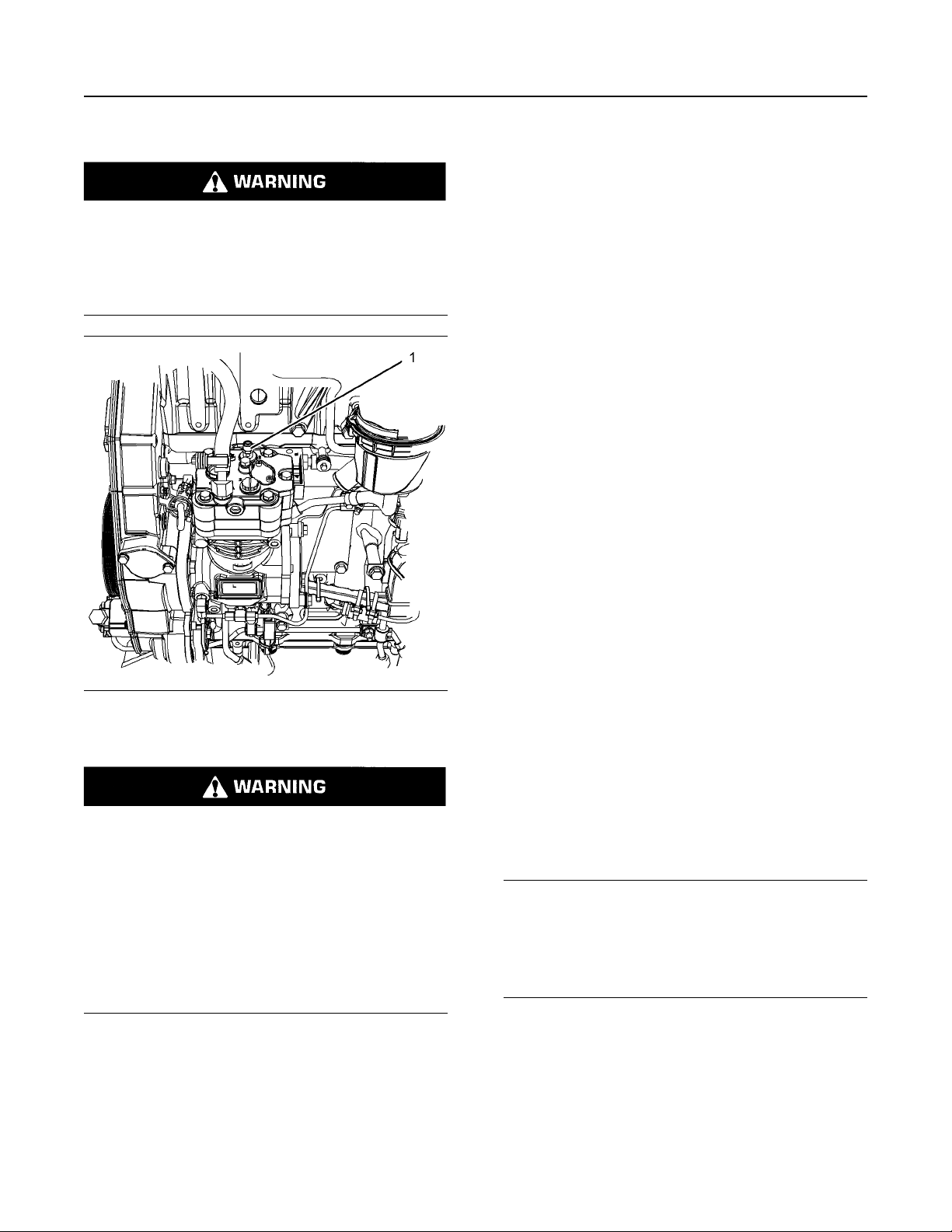
58 SEBU9072
Maintenance Recommendations
Air Shutoff - Test
The pressure relief valve for the air compressor
releases air at 1723 kPa (250 psi). If the pressure
relief valve for the air compressor exhausts, all
personnel should be at a safe distance away from the
Do not disconnect the air line from the air compressor governor without purging the air brake
and the auxiliary air systems. Failure to purge the
air brake and the auxiliary air systems before removing the air compressor and/or the air lines
could cause personal injury.
air compressor. All personnel should also stay clear
of the air compressor when the engine is operating
and the air compressor is exposed.
Consult your Perkins distributor for assistance.
i06111591
Air Shutoff - Test
To ensure that the air shutoff valve always shuts
down when the engine ingests gaseous fumes,
perform the test below at each oil change. A test
failure can indicate wear in the block off plate to valve
body interface and/or the bearing system.
1. Place engine at low idle speed. Ensure all
accessories that are normally used for the
application are in use, like a fan, or power takeoffs.
Illustration 27 g03813903
Typical example
(1) Pressure relief valve
If the air compressor pressure relief valve that is
mounted in the air compressor cylinder head is
bypassing compressed air, there is a malfunction
in the air system, possibly ice blockage. Under
these conditions, your engine may have insufficient air for normal brake operation.
Do not operate the engine until the reason for the
air bypass is identified and corrected. Failure to
heed this warning could lead to property damage,
personal injury, or death to the operator or
bystanders.
2. Actuate the air shutoff manually. On electrical
operator air shutoffs, utilize an applicable power
supply or jumper cables from the battery to
energize the air shut-off solenoid. Ensure that the
solenoid receives only a momentary signal to
prevent overheating. On hydraulic operator air
shutoffs, found on some hazardous location units,
actuate by pulling the emergency stop handle.
3. Ensure that air shutoff was actuated and that the
engine comes to a complete stop.
Note: As every application has different parasitic
loads and inertia, the duration for the problem to
occur cannot be specified. However, if the engine
stumbles or attempts to continue running, these
symptoms may be an indication that worn
components may need replacement.
NOTICE
Actuating the air shutoff valve may result in oil leakage past the shaft seal in some cases. Repeated actuation of the air shutoff valve during loaded operation
of the engine can result in mechanical damage to the
turbocharger and reduce turbocharger life.
The function of the pressure relief valve is to bypass
air when there is a malfunction in the system for the
air compressor.
i00847451
Air Tank Moisture and
Sediment - Drain
(If Equipped)
Page 59
SEBU9072 59
Maintenance Recommendations
Battery - Recycle
i01878164
Moisture and sediment in the air starting system can
cause the following conditions:
• Freezing
• Corrosion of internal parts
Battery - Replace
• Malfunction of the air starting system
When opening the drain valve, wear protective
gloves, a protective face shield, protective clothing, and protective shoes. Pressurized air could
cause debris to be blown and result in personal
injury.
1. Open the drain valve that is on the bottom of the air
tank. Allow the moisture and sediment to drain.
2. Close the drain valve.
3. Check the air supply pressure. The air starting
motor requires a minimum of 620 kPa (90 psi) of
air pressure to operate properly. The maximum air
pressure must not exceed 1550 kPa (225 psi).
The normal air pressure will be 758 to 965 kPa
(110 to 140 psi).
i02039199
Battery - Recycle
Batteries give off combustible gases which can
explode. A spark can cause the combustible
gases to ignite. This can result in severe personal
injury or death.
Ensure proper ventilation for batteries that are in
an enclosure. Follow the proper procedures in order to help prevent electrical arcs and/or sparks
near batteries. Do not smoke when batteries are
serviced.
The battery cables or the batteries should not be
removed with the battery cover in place. The battery cover should be removed before any servicing is attempted.
Removing the battery cables or the batteries with
the cover in place may cause a battery explosion
resulting in personal injury.
1. Switch the engine to the OFF position. Remove all
electrical loads.
2. Turn off any battery chargers. Disconnect any
battery chargers.
Always recycle a battery. Never discard a battery.
Return used batteries to one of the following
locations:
• A battery supplier
• An authorized battery collection facility
• A recycling facility
3. The NEGATIVE “-” cable connects the NEGATIVE
“-” battery terminal to the NEGATIVE “-” terminal
on the starter motor. Disconnect the cable from the
NEGATIVE “-” battery terminal.
4. The POSITIVE “+” cable connects the POSITIVE
“+” battery terminal to the POSITIVE “+” terminal
on the starting motor. Disconnect the cable from
the POSITIVE “+” battery terminal.
Note: Always recycle a battery. Never discard a
battery. Return used batteries to an appropriate
recycling facility.
5. Remove the used battery.
6. Install the new battery.
Note: Before the cables are connected, ensure that
the engine start switch is OFF.
7. Connect the cable from the starting motor to the
POSITIVE “+” battery terminal.
Page 60

60 SEBU9072
Maintenance Recommendations
Battery Electrolyte Level - Check
8. Connect the cable from the NEGATIVE “-”
terminal on the starter motor to the NEGATIVE “-”
battery terminal.
i02747977
Battery Electrolyte Level Check
When the engine is not run for long periods of time or
when the engine is run for short periods, the batteries
may not fully recharge. Ensure a full charge in order
to help prevent the battery from freezing. If batteries
are correctly charged, the ammeter reading should be
very near zero, when the engine is in operation.
All lead-acid batteries contain sulfuric acid which
can burn the skin and clothing. Always wear a
face shield and protective clothing when working
on or near batteries.
1. Remove the filler caps. Maintain the electrolyte
level to the “FULL” mark on the battery.
If the addition of water is necessary, use distilled
water. If distilled water is not available use clean
water that is low in minerals. Do not use artificially
softened water.
i05424317
Battery or
Battery Cable -
Disconnect
The battery cables or the batteries should not be
removed with the battery cover in place. The battery cover should be removed before any servicing is attempted.
Removing the battery cables or the batteries with
the cover in place may cause a battery explosion
resulting in personal injury.
1. Turn the start switch to the OFF position. Turn the
ignition switch (if equipped) to the OFF position
and remove the key and all electrical loads.
Note: After the engine has stopped, allow 2 minutes
in order for the diesel exhaust fluid lines to be purged
before disconnecting the power.
2. Disconnect the negative battery terminal. Ensure
that the cable cannot contact the terminal. When
four 12 V batteries are involved, 2 negative
connections must be disconnected.
3. Remove the positive connection.
2. Check the condition of the electrolyte with a
suitable battery tester.
3. Install the caps.
4. Keep the batteries clean.
Clean the battery case with one of the following
cleaning solutions:
• Use a solution of 0.1 kg (0.2 lb) baking soda
and 1 L (1 qt) of clean water.
• Use a solution of ammonium hydroxide.
Thoroughly rinse the battery case with clean water.
4. Clean all disconnected connection and battery
terminals.
5. Use a fine grade of sandpaper to clean the
terminals and the cable clamps. Clean the items
until the surfaces are bright or shiny. DO NOT
remove material excessively. Excessive removal of
material can cause the clamps to fit incorrectly.
Coat the clamps and the terminals with a suitable
silicone lubricant or petroleum jelly.
6. Tape the cable connections in order to help prevent
accidental starting.
7. Proceed with necessary system repairs.
8. In order to connect the battery, connect the positive
connection before the negative connector.
i06093624
Belts - Inspect/Replace
(Multi Vee Belt)
Page 61

SEBU9072 61
Maintenance Recommendations
Coolant (DEAC) - Change
To maximize the engine performance, inspect the belt
for wear and for cracking. Replace the belt if the belt
is worn or damaged.
• Inspect the belt for cracks, splits, glazing, grease,
displacement of the cord and evidence of fluid
contamination.
The belt must be replaced if the following conditions
are present.
• The belt has a crack in more than one rib.
• More than one section of the belt is displaced in
one rib of a maximum length of 50.8 mm (2 inch).
During replacement of the belt check the automatic
belt tensioner for wear or damage. Ensure that all
rollers and pulley within the belt system are installed
securely and that pulleys and roller can rotate freely.
To replace the belt, refer to Disassembly and
Assembly, “Alternator Belt - Remove and Install”. If
necessary, replace the belt tensioner. Refer to
Disassembly and Assembly, “Alternator Belt Remove and Install” for the correct procedure.
i06094894
Coolant (DEAC) - Change
Clean the cooling system and flush the cooling
system before the recommended maintenance
interval if the following conditions exist:
• The engine overheats frequently.
• Foaming is observed.
• The oil has entered the cooling system and the
coolant is contaminated.
• The fuel has entered the cooling system and the
coolant is contaminated.
Note: Inspect the water pump and the water
temperature regulator after the cooling system has
been drained.
Illustration 28 g02351659
The cooling system drain valve is towards the bottom
of the radiator.
Drain
Pressurized System: Hot coolant can cause serious burns. To open the cooling system filler cap,
stop the engine and wait until the cooling system
components are cool. Loosen the cooling system
pressure cap slowly in order to relieve the
pressure.
1. Stop the engine and allow the engine to cool.
Loosen the cooling system filler cap slowly in order
to relieve any pressure. Remove the cooling
system filler cap.
2. Open the cooling system drain valve.
Allow the coolant to drain.
Flush
1. Flush the cooling system with clean water in order
to remove any debris.
2. Close the drain valve.
Page 62

62 SEBU9072
Maintenance Recommendations
Coolant (ELC) - Change
NOTICE
Fill the cooling system no faster than 19 L (5 US gal)
per minute to avoid air locks.
3. Fill the cooling system with clean water and
operate the engine, ensure that the thermostat
opens. Stop the engine and allow the engine to
cool.
4. Drain the cooling system.
5. Fill the cooling system with clean water and
operate the engine until the engine is warmed to
82 °C (180 °F).
6. Stop the engine and allow the engine to cool. Drain
the cooling system.
Fill
NOTICE
Fill the cooling system no faster than 19 L (5 US gal)
per minute to avoid air locks.
1. Fill the cooling system with coolant/antifreeze.
Refer to this Operation and Maintenance Manual,
“Fluid Recommendations” topic for more
information on cooling system specifications. Do
not install the cooling system filler cap.
2. Start and run the engine at low idle. Increase the
engine rpm to 1500 rpm. Run the engine at high
idle for 1 minute in order to purge the air from the
cavities of the engine block. Stop the engine.
i06094897
Coolant (ELC) - Change
NOTICE
Perkins ELC must be using with an extender in order
to achieve 12000 hours operation. For more information on a suitable extender contact your Perkins
distributor.
Clean the cooling system and flush the cooling
system before the recommended maintenance
interval if the following conditions exist:
• The engine overheats frequently.
• Foaming is observed.
• The oil has entered the cooling system and the
coolant is contaminated.
• The fuel has entered the cooling system and the
coolant is contaminated.
Note: When the cooling system is cleaned, only
clean water is needed when the ELC is drained and
replaced.
Note: Inspect the water pump and the water
temperature regulator after the cooling system has
been drained.
3. Check the coolant level. Maintain the coolant level
within 13 mm (0.5 inch) below the bottom of the
pipe for filling. Maintain the coolant level within
13 mm (0.5 inch) to the proper level on the sight
glass.
4. Clean the cooling system filler cap. Inspect the
gasket that is on the cooling system filler cap. If the
gasket that is on the cooling system filler cap is
damaged, discard the old filler cap and install a
new filler cap. If the gasket that is on the cooling
system filler cap is not damaged, perform a
pressure test. The correct pressure for the cooling
system filler cap is stamped on the face of the
cooling system filler cap. If the cooling system filler
cap does not retain the correct pressure, install a
new cooling system filler cap.
5. Start the engine. Inspect the cooling system for
leaks and for proper operating temperature.
Page 63
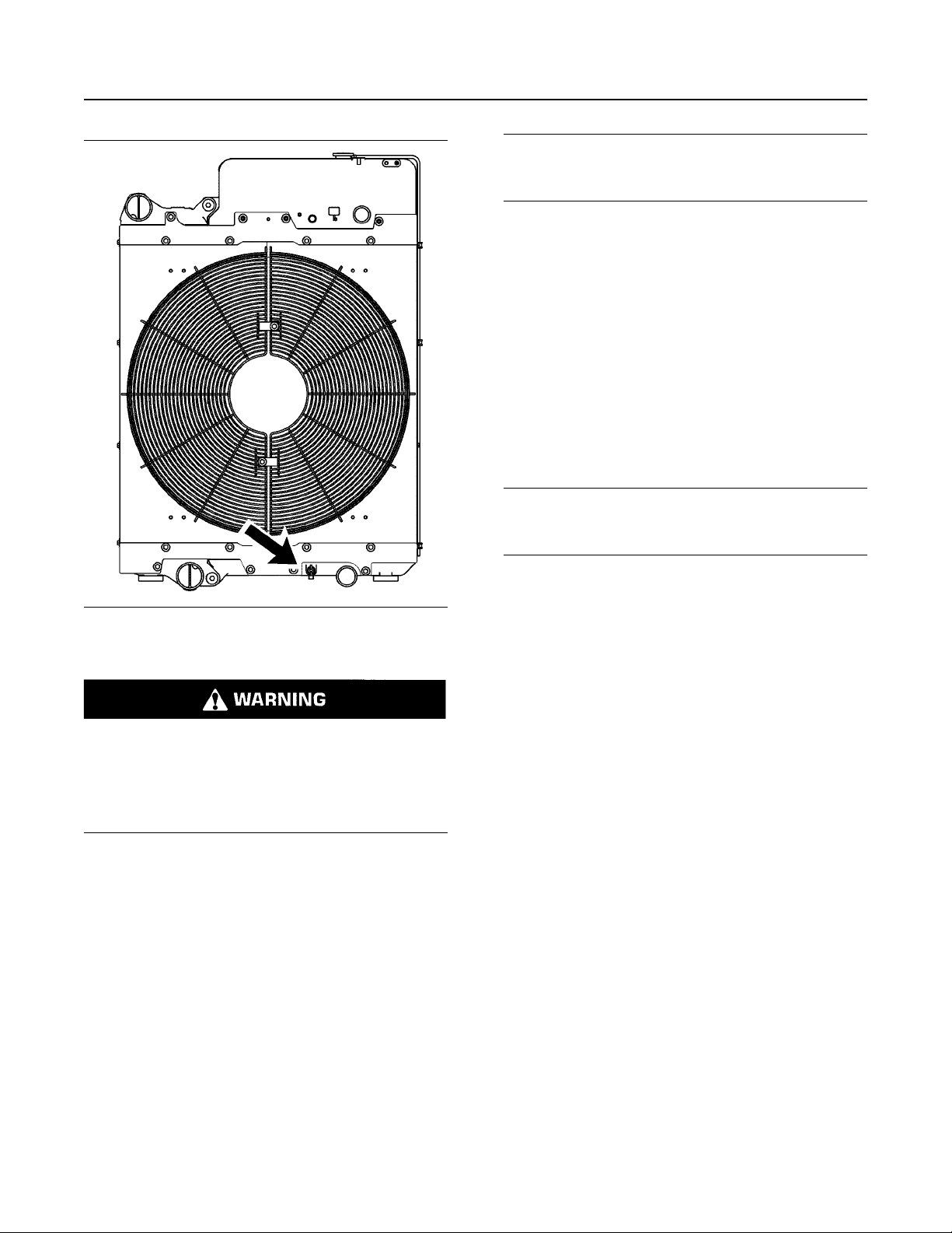
SEBU9072 63
Maintenance Recommendations
Coolant (ELC) - Change
NOTICE
Fill the cooling system no faster than 19 L (5 US gal)
per minute to avoid air locks.
3. Fill the cooling system with clean water. Install the
cooling system filler cap.
4. Start and run the engine at low idle until the
temperature reaches 49 to 66 °C (120 to 150 °F).
5. Stop the engine and allow the engine to cool.
Loosen the cooling system filler cap slowly in order
to relieve any pressure. Remove the cooling
system filler cap. Open the drain valve. Allow the
water to drain. Flush the cooling system with clean
water. Close the drain valve.
Fill
Illustration 29 g02351659
Drain
Pressurized System: Hot coolant can cause serious burns. To open the cooling system filler cap,
stop the engine and wait until the cooling system
components are cool. Loosen the cooling system
pressure cap slowly in order to relieve the
pressure.
1. Stop the engine and allow the engine to cool.
Loosen the cooling system filler cap slowly in order
to relieve any pressure. Remove the cooling
system filler cap.
2. Open the cooling system drain valve.
Allow the coolant to drain.
Flush
1. Flush the cooling system with clean water in order
to remove any debris.
2. Close the drain valve.
NOTICE
Fill the cooling system no faster than 19 L (5 US gal)
per minute to avoid air locks.
1. Fill the cooling system with Extended Life Coolant
(ELC). Refer to this Operation and Maintenance
Manual, “Fluid Recommendations” for more
information on cooling system specifications. Do
not install the cooling system filler cap.
2. Start and run the engine at low idle. Increase the
engine rpm to high idle. Run the engine at high idle
for 1 minute in order to purge the air from the
cavities of the engine block. Stop the engine.
3. Check the coolant level. Maintain the coolant level
within 13 mm (0.5 inch) below the bottom of the
pipe for filling. Maintain the coolant level within
13 mm (0.5 inch) to the proper level on the sight
glass.
4. Clean the cooling system filler cap. Inspect the
gasket that is on the cooling system filler cap. Only
install the used filler cap if the gasket is not
damaged. Test the cap for the correct pressure.
The correct pressure for the cooling system filler
cap is stamped on the face of the cooling system
filler cap. If the cooling system filler cap does not
retain the correct pressure, install a new cooling
system filler cap.
5. Start the engine. Inspect the cooling system for
leaks and for proper operating temperature.
Page 64

64 SEBU9072
Maintenance Recommendations
Coolant Extender (ELC) - Add
i05197396
Coolant Extender (ELC) - Add
In order for Perkins ELC to achieve 12000 hours an
extender must be added at 6000 hours. For a suitable
extender, contact your Perkins dealer or Perkins
distributor.
i03842450
Coolant Level - Check
Check the coolant level when the engine is stopped
and cool.
Illustration 30 g00285520
Cooling system filler cap
Pressurized System: Hot coolant can cause serious burns. To open the cooling system filler cap,
stop the engine and wait until the cooling system
components are cool. Loosen the cooling system
pressure cap slowly in order to relieve the
pressure.
Illustration 31 g00103639
Typical filler cap gaskets
3. Clean the cooling system filler cap and check the
condition of the filler cap gaskets. Replace the
cooling system filler cap if the filler cap gaskets are
damaged. Reinstall the cooling system filler cap.
4. Inspect the cooling system for leaks.
i03644948
Cooling System Supplemental
Coolant Additive (SCA) - Test/
Add
Cooling system coolant additive contains alkali.
To help prevent personal injury, avoid contact
with the skin and the eyes. Do not drink cooling
system coolant additive.
Test for SCA Concentration
1. Remove the cooling system filler cap slowly in
order to relieve pressure.
2. Maintain the coolant level within 13 mm (0.5 inch)
of the bottom of the filler pipe. If the engine is
equipped with a sight glass, maintain the coolant
level to the proper level in the sight glass.
Heavy-Duty Coolant/Antifreeze and SCA
NOTICE
Do not exceed the recommended six percent supplemental coolant additive concentration.
Use a Coolant Conditioner Test Kit in order to check
the concentration of the SCA.
Page 65
SEBU9072 65
Maintenance Recommendations
Driven Equipment - Check
Add the SCA, If Necessary
NOTICE
Do not exceed the recommended amount of supplemental coolant additive concentration. Excessive supplemental coolant additive concentration can form
deposits on the higher temperature surfaces of the
cooling system, reducing the engine's heat transfer
characteristics. Reduced heat transfer could cause
cracking of the cylinder head and other high temperature components. Excessive supplemental coolant
additive concentration could also result in radiator
tube blockage, overheating, and/or accelerated water
pump seal wear. Never use both liquid supplemental
coolant additive and the spin-on element (if equipped)
at the same time. The use of those additives together
could result in supplemental coolant additive concentration exceeding the recommended maximum.
Pressurized System: Hot coolant can cause serious burns. To open the cooling system filler cap,
stop the engine and wait until the cooling system
components are cool. Loosen the cooling system
pressure cap slowly in order to relieve the
pressure.
4. Clean the cooling system filler cap and inspect the
gasket. If the gasket is damaged, discard the old
filler cap and install a new filler cap. If the gasket is
not damaged, use a suitable pressurizing pump in
order to pressure test the filler cap. The correct
pressure is stamped on the face of the filler cap. If
the filler cap does not retain the correct pressure,
install a new filler cap.
i02151646
Driven Equipment - Check
Refer to the OEM specifications for more information
on the following maintenance recommendations for
the driven equipment:
• Inspection
• Adjustment
• Lubrication
• Other maintenance recommendations
Perform any maintenance for the driven equipment
which is recommended by the OEM.
NOTICE
When any servicing or repair of the engine cooling
system is performed the procedure must be performed with the engine on level ground. This will allow
you to accurately check the coolant level. This will also help in avoiding the risk of introducing an air lock
into the coolant system.
1. Slowly loosen the cooling system filler cap in order
to relieve the pressure. Remove the cooling
system filler cap.
Note: Always discard drained fluids according to local
regulations.
2. If necessary, drain some coolant from the cooling
system into a suitable container in order to allow
space for the extra SCA.
3. Add the correct amount of SCA. Refer to the
Operation and Maintenance Manual, “Refill
Capacities and Recommendations” for more
information on SCA requirements.
i02568158
Engine - Clean
Personal injury or death can result from high
voltage.
Moisture can create paths of electrical
conductivity.
Make sure that the electrical system is OFF. Lock
out the starting controls and tag the controls ““DO
NOT OPERATE”” .
NOTICE
Accumulated grease and oil on an engine is a fire
hazard. Keep the engine clean. Remove debris and
fluid spills whenever a significant quantity accumulates on the engine.
Periodic cleaning of the engine is recommended.
Steam cleaning the engine will remove accumulated
oil and grease. A clean engine provides the following
benefits:
Page 66

66 SEBU9072
Maintenance Recommendations
Engine Air Cleaner Element (Dual Element) - Inspect/Clean/Replace
• Easy detection of fluid leaks
• Maximum heat transfer characteristics
• Ease of maintenance
Note: Caution must be used in order to prevent
electrical components from being damaged by
excessive water when you clean the engine. Avoid
electrical components such as the alternator, the
starter, and the Electronic Control Module (ECM).
i05207494
Engine Air Cleaner Element
(Dual
Element) - Inspect/Clean/
Replace
NOTICE
Never run the engine without an air cleaner element
installed. Never run the engine with a damaged air
cleaner element. Do not use air cleaner elements with
damaged pleats, gaskets or seals. Dirt entering the
engine causes premature wear and damage to engine components. Air cleaner elements help to prevent airborne debris from entering the air inlet.
Replace the dirty air cleaner elements with clean air
cleaner elements. Before installation, the air cleaner
elements should be thoroughly checked for tears and/
or holes in the filter material. Inspect the gasket or the
seal of the air cleaner element for damage. Maintain a
supply of suitable air cleaner elements for
replacement purposes.
Dual Element Air Cleaners
The dual element air cleaner contains a primary air
cleaner element and a secondary air cleaner
element.
The primary air cleaner element can be used up to six
times if the element is properly cleaned and properly
inspected. The primary air cleaner element should be
replaced at least one time per year. This replacement
should be performed regardless of the number of
cleanings.
The secondary air cleaner element is not serviceable.
Refer to the OEM information for instructions in order
to replace the secondary air cleaner element.
When the engine is operating in environments that
are dusty or dirty, air cleaner elements may require
more frequent replacement.
NOTICE
Never service the air cleaner element with the engine
running since this will allow dirt to enter the engine.
Servicing the Air Cleaner Elements
Note: The air filter system may not have been
provided by Perkins . The procedure that follows is
for a typical air filter system. Refer to the OEM
information for the correct procedure.
If the air cleaner element becomes plugged, the air
can split the material of the air cleaner element.
Unfiltered air will drastically accelerate internal engine
wear. Refer to the OEM information for the correct air
cleaner elements for your application.
• Check the precleaner (if equipped) and the dust
bowl daily for accumulation of dirt and debris.
Remove any dirt and debris, as needed.
• Operating in dirty conditions may require more
frequent service of the air cleaner element.
• The air cleaner element should be replaced at
least one time per year. This replacement should
be performed regardless of the number of
cleanings.
Illustration 32 g00736431
(1) Cover
(2) Primary air cleaner element
(3) Secondary air cleaner element
(4) Air inlet
1. Remove the cover. Remove the primary air cleaner
element.
2. The secondary air cleaner element should be
removed and discarded for every three cleanings
of the primary air cleaner element.
Note: Refer to “Cleaning the Primary Air Cleaner
Elements”.
3. Cover the air inlet with tape in order to keep out
dirt.
4. Clean the inside of the air cleaner cover and body
with a clean, dry cloth.
Page 67

SEBU9072 67
Maintenance Recommendations
Engine Air Cleaner Element (Dual Element) - Inspect/Clean/Replace
Pressurized Air
5. Remove the tape from the air inlet. Install the
secondary air cleaner element. Install a primary air
cleaner element that is new or cleaned.
6. Install the air cleaner cover.
7. Reset the air cleaner service indicator.
Cleaning the Primary Air Cleaner
Elements
Refer to the OEM information in order to determine
the number of times that the primary filter element
can be cleaned. When the primary air cleaner
element is cleaned, check for rips or tears in the filter
material. The primary air cleaner element should be
replaced at least one time per year. This replacement
should be performed regardless of the number of
cleanings.
NOTICE
Do not tap or strike the air cleaner element.
Personal injury can result from air pressure.
Personal injury can result without following proper procedure. When using pressure air, wear a
protective face shield and protective clothing.
Maximum air pressure at the nozzle must be less
than 205 kPa (30 psi) for cleaning purposes.
Pressurized air can be used to clean primary air
cleaner elements that have not been cleaned more
than three times. Use filtered, dry air with a maximum
pressure of 207 kPa (30 psi). Pressurized air will not
remove deposits of carbon and oil.
Do not wash the primary air cleaner element.
Use low pressure (207 kPa 30 psi maximum) pressurized air or vacuum cleaning to clean the primary air
cleaner element.
Take extreme care in order to avoid damage to the air
cleaner elements.
Do not use air cleaner elements that have damaged
pleats, gaskets, or seals.
Refer to the OEM information in order to determine
the number of times that the primary air cleaner
element can be cleaned. Do not clean the primary air
filter element more than three times. The primary air
cleaner element must be replaced at least one time
per year.
Cleaning the air filter element will not extend the life
of the air filter element.
Visually inspect the primary air cleaner element
before cleaning. Inspect air cleaner elements for
damage to the pleats, the seals, the gaskets, and the
outer cover. Discard any damaged air cleaner
element.
Two methods may be used in order to clean the
primary air cleaner element:
• pressurized air
• Vacuum cleaning
Illustration 33 g00281692
Note: When the primary air cleaner elements are
cleaned, always begin with the clean side (inside) in
order to force dirt particles toward the dirty side
(outside).
Aim the air hose so that air flows along the length of
the filter. Follow the direction of the paper pleats in
order to prevent damage to the pleats. Do not aim the
air directly at the face of the paper pleats.
Note: Refer to “Inspecting the Primary Air Cleaner
Elements”.
Vacuum Cleaning
Vacuum cleaning is a good method for removing
accumulated dirt from the dirty side (outside) of a
primary air cleaner element. Vacuum cleaning is
especially useful for cleaning primary air cleaner
elements which require daily cleaning because of a
dry, dusty environment.
Cleaning from the clean side (inside) with pressurized
air is recommended prior to vacuum cleaning the dirty
side (outside) of a primary air cleaner element.
Page 68

68 SEBU9072
Maintenance Recommendations
Engine Air Cleaner Element (Single Element) - Inspect/Clean/Replace
Note: Refer to “Inspecting the Primary Air Cleaner
Elements”.
Inspecting the Primary Air Cleaner
Elements
Illustration 34 g00281693
Inspect the clean, dry primary air cleaner element.
Use a 60 W blue light in a dark room or in a similar
facility. Place the blue light in the primary air cleaner
element. Rotate the primary air cleaner element.
Inspect the primary air cleaner element for tears and/
or holes. Inspect the primary air cleaner element for
light that may show through the filter material. If it is
necessary in order to confirm the result, compare the
primary air cleaner element to a new primary air
cleaner element that has the same part number.
Do not use a primary air cleaner element that has any
tears and/or holes in the filter material. Do not use a
primary air cleaner element with damaged pleats,
gaskets, or seals. Discard damaged primary air
cleaner elements.
i04150572
NOTICE
Never run the engine without an air cleaner element
installed. Never run the engine with a damaged air
cleaner element. Do not use air cleaner elements with
damaged pleats, gaskets or seals. Dirt entering the
engine causes premature wear and damage to engine components. Air cleaner elements help to prevent airborne debris from entering the air inlet.
NOTICE
Never service the air cleaner element with the engine
running since this will allow dirt to enter the engine.
Illustration 35 g00310664
(1) Air cleaner cover
(2) Air filter element
(3) Air inlet
1. Remove air cleaner cover (1) and remove air filter
element (2).
2. Cover air inlet (3) with tape or a clean cloth so that
debris cannot enter the air inlet.
Engine Air Cleaner Element
(Single Element) - Inspect/
Clean/Replace
Perform the Operation and Maintenance Manual,
“Engine Air Cleaner Service Indicator-Inspect”
procedure and perform the Operation and
Maintenance Manual, “Engine Air Precleaner Check/
Clean” procedure (if equipped) before performing the
following procedure.
3. Clean the inside of air cleaner cover (1). Clean the
body that holds the air cleaner element.
4. Inspect the replacement element for the following
items:damage, dirt and debris.
5. Remove the seal from the opening of the air inlet.
6. Install a clean, undamaged air filter element (2).
7. Install air cleaner cover (1).
8. Reset the air cleaner service indicator.
Page 69

SEBU9072 69
Maintenance Recommendations
Engine Air Cleaner Service Indicator - Inspect
i06103548
Engine Air Cleaner Service
Indicator - Inspect
(If Equipped)
Some engines may be equipped with a different
service indicator.
Some engines are equipped with a differential gauge
for inlet air pressure. The differential gauge for inlet
air pressure displays the difference in the pressure
that is measured before and after the air cleaner
element. As the air cleaner element becomes dirty,
the pressure differential rises. If your engine is
equipped with a different type of service indicator,
follow the OEM recommendations in order to service
the air cleaner service indicator.
The service indicator may be mounted on the clean
side of the air cleaner housing or in a remote location.
If the service indicator does not reset easily, or if the
core does not latch at the greatest vacuum, the
service indicator should be replaced. If the new
service indicator will not reset, the hole for the service
indicator may be plugged.
If necessary, replace the service indicator more
frequently in environments that are severely dusty.
Replace the service indicator annually regardless of
the operating conditions. Replace the service
indicator when the engine is overhauled, and
whenever major engine components are replaced.
Note: When a new service indicator is installed,
excessive force may crack the top of the service
indicator. Tighten the service indicator to a torque of
2 N·m (18 lb in).
i06102339
Engine Crankcase Breather Clean
Illustration 36 g00103777
Typical service indicator
Observe the service indicator. The air cleaner
element should be cleaned or the air cleaner element
should be replaced when one of the following
conditions occur:
• The yellow diaphragm enters the red zone.
• The red piston locks in the visible position.
Test the Service Indicator
Service indicators are important instruments.
• Check for ease of resetting. The service indicator
should reset in less than three pushes.
Hot oil and hot components can cause personal
injury. Do not allow hot oil or hot components to
contact the skin.
NOTICE
Ensure that the engine is stopped before any servicing or repair is performed.
Ensure that the breather assembly is clean before
removing any parts.
• Check the movement of the service indicator core
when the engine is run at full load speed. The core
should latch approximately at the greatest vacuum
that is attained.
Page 70

70 SEBU9072
Maintenance Recommendations
Engine Mounts - Inspect
Any engine mount that shows deterioration should be
replaced. Refer to the OEM information for the
recommended torques.
i04288290
Engine Oil Level - Check
Hot oil and hot components can cause personal
injury. Do not allow hot oil or hot components to
contact the skin.
Illustration 37 g03810243
1. Loosen clip (5) and remove outlet hose (6). Ensure
that hose is clean internally and free from damage.
2. Remove bolts (2) and remove cover (1). Remove
gasket (3).
3. Remove element (4).
4. Install new element (4) and new gasket (3).
5. Install cover (1) and install all bolts (2). Tighten
bolts (2) to a torque of 12 N·m (106 lb in).
6. Install hose (6) with clip (5), tighten clip securely.
i02323089
Engine Mounts - Inspect
Note: The engine mounts may not have been
supplied by Perkins. Refer to the OEM information for
further information on the engine mounts and the
correct bolt torque.
Inspect the engine mounts for deterioration and for
correct bolt torque. Engine vibration can be caused
by the following conditions:
• Incorrect mounting of the engine
Illustration 38 g02455244
Typical installation of the oil level gauge
(1) Oil filler cap
(2) Oil level gauge
Illustration 39 g00110310
Partial view of the oil level gauge
(Y) “ADD” mark
(X) “FULL” mark
NOTICE
Perform this maintenance with the engine stopped.
• Deterioration of the engine mounts
• Loose engine mounts
Page 71

SEBU9072 71
Maintenance Recommendations
Engine Oil Sample - Obtain
NOTICE
Engine damage can occur if the crankcase is filled
above the “FULL” mark on the oil level gauge
(dipstick).
An overfull crankcase can cause the crankshaft to dip
into the oil. This will reduce the power that is developed and also force air bubbles into the oil. These
bubbles (foam) can cause the following problems: reduction of the oil's ability to lubricate, reduction of oil
pressure, inadequate cooling, oil blowing out of the
crankcase breathers and excessive oil consumption.
Excessive oil consumption will cause deposits to form
on the pistons and in the combustion chamber. Deposits in the combustion chamber lead to the following problems: guttering of the valves, packing of
carbon under the piston rings and wear of the cylinder
liner.
If the oil level is above the “FULL” mark on the oil level gauge, drain some of the oil immediately.
1. Remove the oil filler cap and check the oil level.
Maintain the oil level between the “ADD” mark (Y)
and the “FULL” mark (X) on the oil level gauge
(1). Do not fill the crankcase above “FULL” mark
(X).
2. In order to choose the correct type of oil for this
engine, refer to this Operation and Maintenance
Manual, “Fluid Recommendations”.
3. Clean the oil filler cap. Install the oil filler cap.
4. Record the amount of oil that is added. For the next
oil sample and analysis, include the total amount of
oil that has been added since the previous sample.
Recording this information helps to provide the
most accurate oil analysis.
i01907674
Engine Oil Sample - Obtain
Obtain the Sample and the Analysis
Hot oil and hot components can cause personal
injury. Do not allow hot oil or hot components to
contact the skin.
In order to help obtain the most accurate analysis,
record the following information before an oil sample
is taken:
• The date of the sample
• Engine model
• Engine number
• Service hours on the engine
• The number of hours that have accumulated since
the last oil change
• The amount of oil that has been added since the
last oil change
Ensure that the container for the sample is clean and
dry. Also ensure that the container for the sample is
clearly labelled.
To ensure that the sample is representative of the oil
in the crankcase, obtain a warm, well mixed oil
sample.
To avoid contamination of the oil samples, the tools
and the supplies that are used for obtaining oil
samples must be clean.
The sample can be checked for the following: the
quality of the oil, the existence of any coolant in the
oil, the existence of any ferrous metal particles in the
oil and the existence of any nonferrous metal
particles in the oil.
i06219337
Engine Oil and Filter - Change
The condition of the engine lubricating oil may be
checked at regular intervals as part of a preventive
maintenance program. Perkins include an oil
sampling valve as an option. The oil sampling valve
(if equipped) is included in order to regularly sample
the engine lubricating oil. The oil sampling valve is
positioned on the oil filter head or the oil sampling
valve is positioned on the cylinder block.
Perkins recommends using a sampling valve in order
to obtain oil samples. The quality and the consistency
of the samples are better when a sampling valve is
used. The location of the sampling valve allows oil
that is flowing under pressure to be obtained during
normal engine operation.
Hot oil and hot components can cause personal
injury. Do not allow hot oil or hot components to
contact the skin.
Page 72

72 SEBU9072
Maintenance Recommendations
Engine Oil and Filter - Change
NOTICE
Care must be taken to ensure that fluids are contained during performance of inspection, maintenance, testing, adjusting and repair of the product. Be
prepared to collect the fluid with suitable containers
before opening any compartment or disassembling
any component containing fluids.
Dispose of all fluids according to local regulations and
mandates.
NOTICE
Keep all parts clean from contaminants.
Contaminants may cause rapid wear and shortened
component life.
Do not drain the engine lubricating oil when the
engine is cold. As the engine lubricating oil cools,
suspended waste particles settle on the bottom of the
oil pan. The waste particles are not removed with
draining cold oil. Drain the oil pan with the engine
stopped. Drain the oil pan with the oil warm. This
draining method allows the waste particles that are
suspended in the oil to be drained properly.
Replace the Oil Filter
NOTICE
Perkins oil filters are manufactured to Perkins specifications. Use of an oil filter that is not recommended
by Perkins could result in severe damage to the engine bearings, and crankshaft. As a result of the larger waste particles from unfiltered oil entering the
engine lubricating system. Only use oil filters recommended by Perkins.
1. Remove the oil filter with a suitable tool.
Failure to follow this recommended procedure will
cause the waste particles to be recirculated through
the engine lubrication system with the new oil.
Drain the Engine Lubricating Oil
Note: Ensure that the vessel that will be used is large
enough to collect the waste oil.
After the engine has been run at the normal operating
temperature, stop the engine. Use one of the
following methods to drain the engine oil pan:
• If the engine is equipped with a drain valve, turn
the drain valve knob counterclockwise in order to
drain the oil. After the oil has drained, turn the
drain valve knob clockwise in order to close the
drain valve.
• If the engine is not equipped with a drain valve,
remove the oil drain plug in order to allow the oil to
drain.
After the oil has drained, the oil drain plug should be
cleaned. If necessary, replace the O ring seal and
install the plug. Tighten the drain plug to 35 N·m
(26 lb ft).
Illustration 40 g03859841
2. Clean sealing surface (3).
3. Apply clean engine oil to O ring seal (2) for the new
oil filter (1).
NOTICE
Do not fill the oil filter with oil before installing. This oil
would not be filtered and could be contaminated.
Contaminated oil can cause accelerated wear to engine components.
4. Install the new oil filter (1). Spin on the oil filter until
the O ring contacts the sealing surface (3). Then
rotate the oil filter 1 full turn. Remove the container
and disposal of the waste oil in accordance with
local regulations.
Fill the Oil Pan
Page 73
SEBU9072 73
Maintenance Recommendations
Engine Valve Lash - Check
1. Remove the oil filler cap. Refer to this Operation
and Maintenance Manual, “Fluid
Recommendations” for more information on
suitable oils. Fill the oil pan with the correct amount
of new engine lubricating oil. Refer to this
Operation and Maintenance Manual, “Refill
Capacities” for more information on refill
capacities.
2. Start the engine and run the engine at LOW IDLE
for 2 minutes. Perform this procedure in order to
ensure that the lubrication system has oil and that
the oil filters are filled. Inspect the oil filter for oil
leaks.
3. Stop the engine and allow the oil to drain back to
the oil pan for a minimum of 10 minutes.
4. .Remove the oil level gauge in order to check the
oil level. Maintain the oil level between the ADD
and FULL marks on the side of the oil level gauge.
i06224992
Engine Valve Lash - Check
For engines above 330 kW (442 hp) an initial 500
hours valve lash check is required.
This maintenance is recommended by Perkins as
part of a lubrication and preventive maintenance
schedule in order to help provide maximum engine
life.
NOTICE
Only qualified service personel should perform this
maintenance. Refer to the Service Manual or your authorized Perkins dealer or your Perkins distributor
for the complete valve lash adjustment procedure.
Operation of Perkins engines with incorrect valve
lash can reduce engine efficiency, and also reduce
engine component life.
Ensure that the engine is stopped before measuring
the valve lash. To obtain an accurate measurement,
allow the valves to cool before this maintenance is
performed.
During valve adjustment, visibly inspect the valve
train of wear or damage.
Refer to Systems Operation, Testing and Adjusting,
“Engine Valve Lash - Inspect/Adjust” for more
information.
i06219372
Fuel System - Prime
Fuel leaked or spilled onto hot surfaces or electrical components can cause a fire. To help prevent
possible injury, turn the start switch off when
changing fuel filters or water separator elements.
Clean up fuel spills immediately.
Refer to this Operation and Maintenance Manual,
“General Hazard Information” before any adjustments
or repairs are performed
If necessary, perform minor adjustments. Repair any
leaks from the fuel system and from the cooling,
lubrication, or air systems. Ensure that all
adjustments and repairs are performed by authorized
personnel that have had the correct training.
The fuel system should be primed under the
following conditions:
• The fuel tank is empty or the fuel tank has been
partially drained.
• The engine has been in storage.
• The fuel filter has been replaced.
• The pressure fuel lines have been disconnected.
Ensure that the engine cannot be started while
this maintenance is being performed. To help prevent possible injury, do not use the starting motor
to turn the flywheel.
Hot engine components can cause burns. Allow
additional time for the engine to cool before measuring/adjusting valve lash clearance.
1. Ensure that the key switch is in the OFF position.
Ensure that the fuel tank is full of clean diesel fuel.
Check that the fuel supply valve (if equipped) is in
the “ON” position.
Page 74
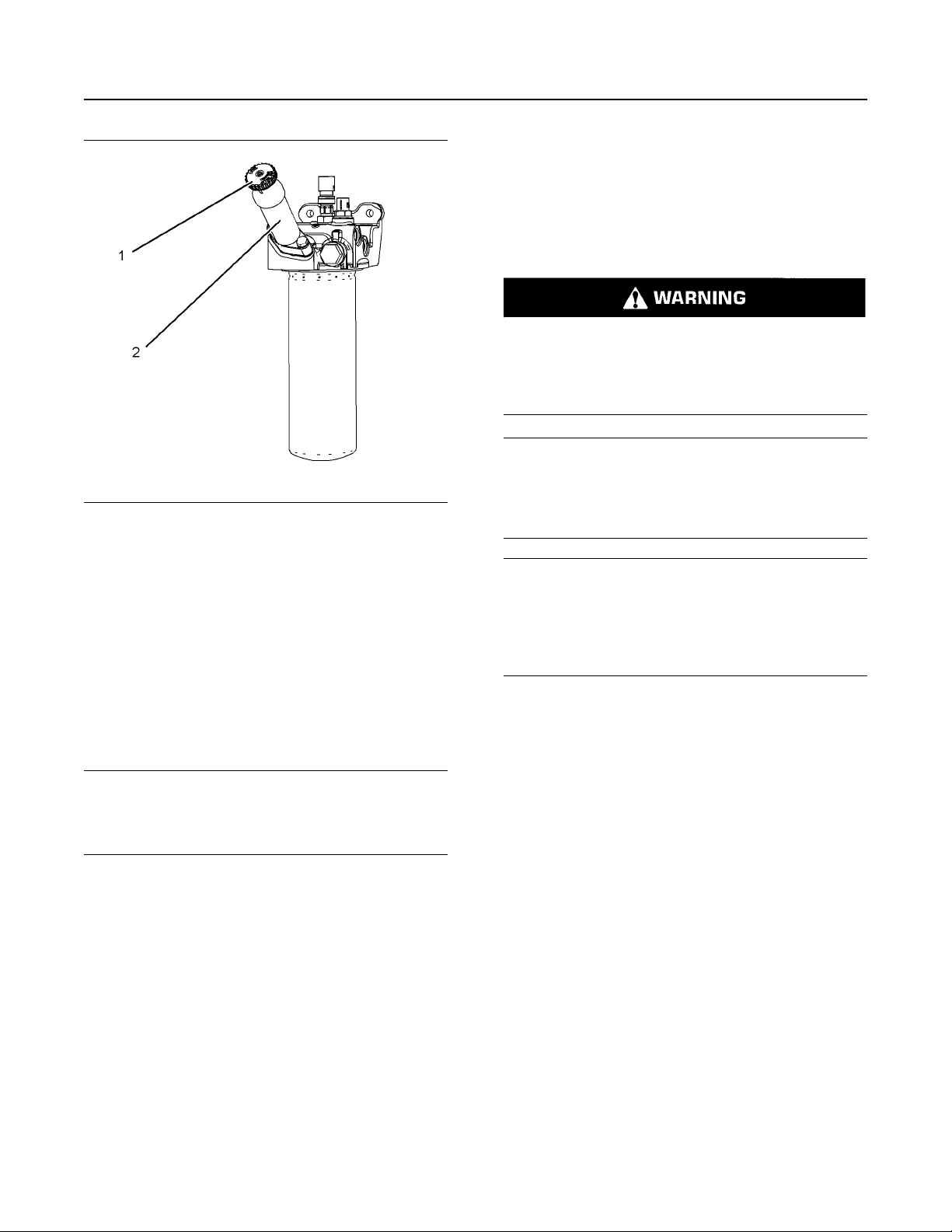
74
Maintenance Recommendations
Fuel System Primary Filter (Water Separator) Element - Replace
Fuel System Primary Filter
(Water Separator) Element Replace
Fuel leaked or spilled onto hot surfaces or electrical components can cause a fire. To help prevent
possible injury, turn the start switch off when
changing fuel filters or water separator elements.
Clean up fuel spills immediately.
Do not allow dirt to enter the fuel system. Thoroughly
clean the area around a fuel system component that
Illustration 41 g03863703
Typical example
will be disconnected. Fit a suitable cover over disconnected fuel system component.
SEBU9072
i06221205
NOTICE
2. Unlock the fuel priming pump handle (1). Turn
handle counter clockwise. Operate the fuel pump
handle until strong pressure can be felt.
3. When strong pressure can be felt, press in the fuel
pump handle and lock the handle into the fuel
pump body (2). In order to lock the handle, turn
handle clockwise.
Note: The stronger the pressure in the fuel system
the quicker the engine will start.
NOTICE
Do not crank the engine continuously for more than
30 seconds. Allow the starting motor to cool for two
minutes before cranking the engine again.
4. Start the engine, refer to this Operation and
Maintenance Manual, “Starting the Engine” for
more information.
5. If the engine will not start, repeat Steps 2 to Step 3.
6. Once the engine starts, allow the engine to operate
with no load for 5 minutes.
NOTICE
Do not fill fuel filters with fuel before installing
them. The fuel will not be filtered and could be
contaminated. Contaminated fuel will cause accelerated wear to fuel system parts. The fuel system
should be primed prior to starting the engine.
Water in the fuel can cause the engine to run rough.
Water in the fuel may cause an electronic unit injector
to fail. If the fuel has been contaminated with water,
the element should be changed before the regularly
scheduled interval.
The primary filter/water separator also provides
filtration in order to help extend the life of the
secondary fuel filter. The element should be changed
regularly. If a vacuum gauge is installed, the primary
filter/water separator should be changed at
50 to 70 kPa (15 to 20 inches Hg).
7. If the engine will not start, refer to Troubleshooting,
“Engine Cranks but will not Start”.
Page 75
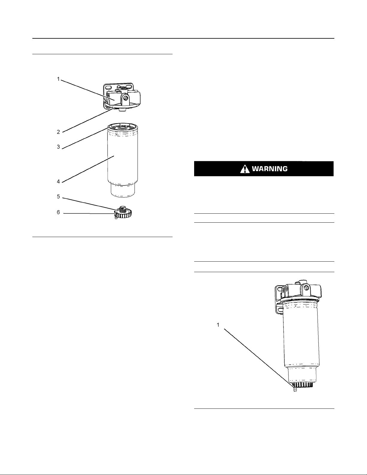
SEBU9072
75
Maintenance Recommendations
Fuel System Primary Filter/Water Separator - Drain
9. The secondary fuel filter should be replaced when
the primary fuel filter is replaced. For more
information refer to this Operation and
Maintenance Manual, “Fuel System Secondary
Filter - Replace”.
10. Dispose of the fluid and old filter in accordance
with local regulations.
i06221208
Fuel System Primary Filter/
Water Separator - Drain
Fuel leaked or spilled onto hot surfaces or electrical components can cause a fire. To help prevent
possible injury, turn the start switch off when
changing fuel filters or water separator elements.
Clean up fuel spills immediately.
Illustration 42 g03860332
Typical example
1. Close the main fuel supply valve.
2. Place a suitable container below the primary fuel
filter in order to catch any fluid that may spill. Clean
any split fluid.
3. Clean the outside of the primary fuel filter.
4. Remove the bowl (6) and O ring seal (5). Using a
suitable tool remove the spin on filter (4).
5. Ensure that the seal surface (2) is clean. Apply
clean diesel fuel to the O ring seal (3) on the new
spin on filter.
6. Install the new spin on filter to the filter base (1).
Spin on the filter until the O ring seal (3) contact
the sealing surface (2). Then, rotate the spin on
filter ¾ of a full turn.
7. Ensure that the bowl (6) is clean. If necessary,
install a new O ring seal (5) into bowl (6) and install
bowl to the filter assembly.
8. Tighten the bowl by hand, maximum torque for the
bowl is 10 N·m (88 lb in).
NOTICE
Do not allow dirt to enter the fuel system. Thoroughly
clean the area around a fuel system component that
will be disconnected. Fit a suitable cover over disconnected fuel system component.
Illustration 43 g03860334
Typical example
Page 76

76 SEBU9072
Maintenance Recommendations
Fuel System Secondary Filter - Replace
1. Ensure that the engine is stopped. Open drain (1).
The drain is a self-ventilated drain. Catch the
draining water in a suitable container. Dispose of
the water properly.
2. Close drain.
NOTICE
The water separator is under suction during normal
engine operation. Ensure that the drain valve is tightened securely to help prevent air from entering the
fuel system.
i06221215
Fuel System Secondary Filter Replace
Fuel leaked or spilled onto hot surfaces or electrical components can cause a fire. To help prevent
possible injury, turn the start switch off when
changing fuel filters or water separator elements.
Clean up fuel spills immediately.
NOTICE
Do not allow dirt to enter the fuel system. Thoroughly
clean the area around a fuel system component that
will be disconnected. Fit a suitable cover over any disconnected fuel system components.
NOTICE
Ensure that the engine is stopped before any servicing or repair is performed.
Refer to Systems Operation, Testing, and
Adjusting, “Cleanliness of Fuel System
Components” for detailed information on the
standards of cleanliness that must be observed
during ALL work on the fuel system.
1. Turn the fuel supply valve (if equipped) OFF before
performing this maintenance.
2. Place a suitable container under the fuel filters in
order to catch any fuel that might spill. Clean up
any spilled fuel. Clean the outside body of both fuel
filters.
Illustration 44 g03860337
Typical example
3. The residual fuel pressure in the fuel system may
need relieving. Wait from 1 minute to 5 minutes
until the fuel pressure has lowered.
4. Using a suitable tool remove the spin on fuel filter
(3).
5. Ensure that the sealing surface (1) is clean.
Lubricate the O ring seal (2) on the new spin on
filter with clean diesel fuel.
6. Install the new spin on filter (3) to the filter base.
Spin on the filter until the O ring seal (2) contact
the sealing surface (1). Then, rotate the spin on
filter 1 full turn.
7. Turn on the fuel supply valve. Dispose of the fluid
and old filter in accordance with local regulations.
8. The primary fuel filter the secondary fuel filter must
be replaced at the same time. Refer to the
Operation and Maintenance Manual, “Fuel System
Primary Filter (Water Separator) Element Replace”. The engine will need to be purged of air.
With primary and secondary fuel filters replace,
Refer to Operation and Maintenance Manual, “Fuel
System Prime”.
Page 77
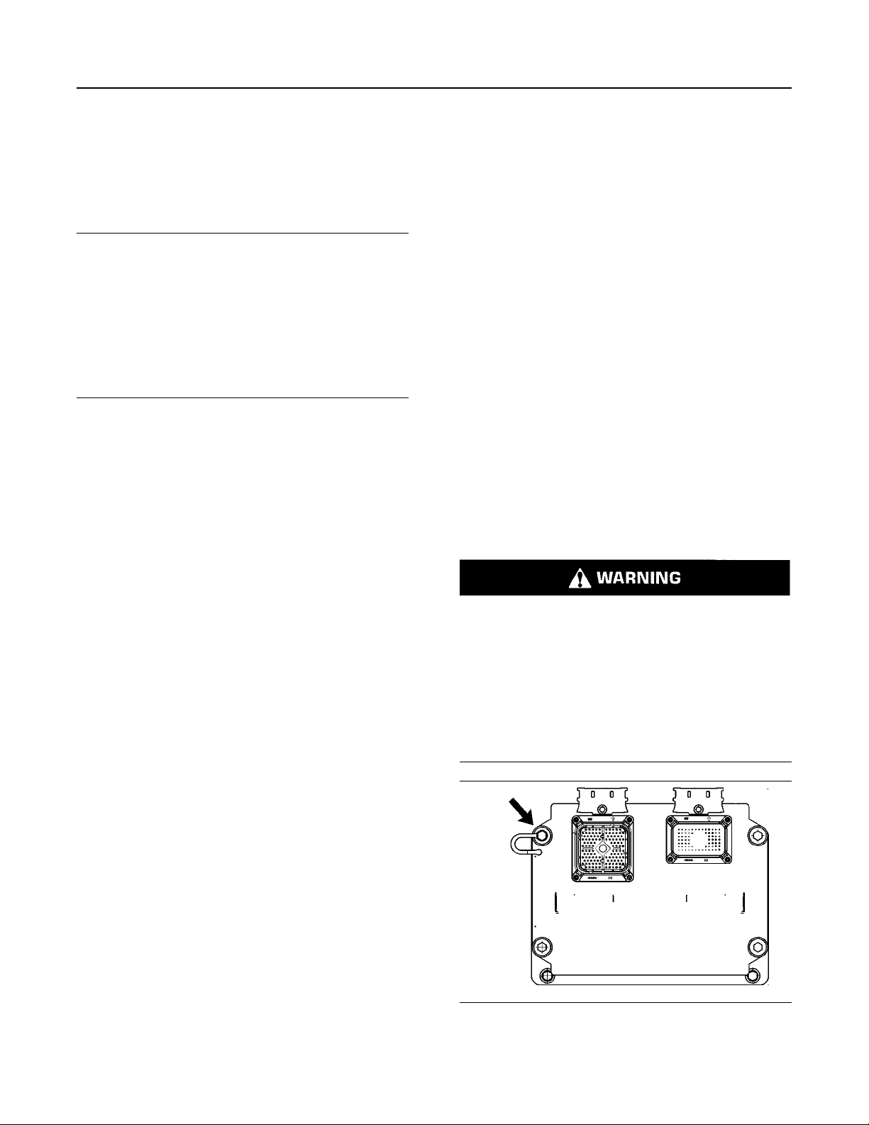
SEBU9072
77
Maintenance Recommendations
Fuel Tank Water and Sediment - Drain
i02348492
Fuel Tank Water and Sediment
- Drain
NOTICE
Care must be taken to ensure that fluids are contained during performance of inspection, maintenance, testing, adjusting and repair of the product. Be
prepared to collect the fluid with suitable containers
before opening any compartment or disassembling
any component containing fluids.
Dispose of all fluids according to local regulations and
mandates.
Fuel Tank
Fuel quality is critical to the performance and to the
service life of the engine. Water in the fuel can cause
excessive wear to the fuel system.
Water can be introduced into the fuel tank when the
fuel tank is being filled.
Fuel Storage Tanks
Drain the water and the sediment from the fuel
storage tank at the following intervals:
• Weekly
• Service intervals
• Refill of the tank
This will help prevent water or sediment from being
pumped from the storage tank into the engine fuel
tank.
If a bulk storage tank has been refilled or moved
recently, allow adequate time for the sediment to
settle before filling the engine fuel tank. Internal
baffles in the bulk storage tank will also help trap
sediment. Filtering fuel that is pumped from the
storage tank helps to ensure the quality of the fuel.
When possible, water separators should be used.
i05970985
Grounding Stud - Inspect/
Clean/Tighten
Condensation occurs during the heating and cooling
of fuel. The condensation occurs as the fuel passes
through the fuel system and the fuel returns to the
fuel tank. This causes water to accumulate in fuel
tanks. Draining the fuel tank regularly and obtaining
fuel from reliable sources can help to eliminate water
in the fuel.
Drain the Water and the Sediment
Fuel tanks should contain some provision for draining
water and draining sediment from the bottom of the
fuel tanks.
Open the drain valve on the bottom of the fuel tank in
order to drain the water and the sediment. Close the
drain valve.
Check the fuel daily. Allow five minutes after the fuel
tank has been filled before draining water and
sediment from the fuel tank.
Fill the fuel tank after operating the engine in order to
drive out moist air. This will help prevent
condensation. Do not fill the tank to the top. The fuel
expands as the fuel gets warm. The tank may
overflow.
Some fuel tanks use supply pipes that allow water
and sediment to settle below the end of the fuel
supply pipe. Some fuel tanks use supply lines that
take fuel directly from the bottom of the tank. If the
engine is equipped with this system, regular
maintenance of the fuel system filter is important.
The connection of battery cables to a battery and
the disconnection of battery cables from a battery
may cause an explosion which may result in injury or death. The connection and the disconnection of other electrical equipment may also cause
an explosion which may result in injury or death.
The procedures for the connection and the disconnection of battery cables and other electrical
equipment should only be performed in a nonexplosive atmosphere.
Illustration 45 g01376112
The electronics grounding stud is located on the
upper left corner of the engine control module.
Page 78

78 SEBU9072
Maintenance Recommendations
Hoses and Clamps - Inspect/Replace
Inspect the OEM harness for good connections.
Inspect the condition of the OEM harness.
The electronics grounding stud must have a wire
ground to the battery. Tighten the electronics
grounding stud at every oil change. Ground wires and
straps should be combined at engine grounds. All
grounds should be tight and free of corrosion.
• Clean the electronics grounding stud and the
terminals for the ground strap with a clean cloth.
• If the connections are corroded, clean the
connections with a solution of baking soda and
water.
• Keep the electronics grounding stud and the strap
clean and coated with MPGM grease or petroleum
jelly.
i06103230
Hoses and Clamps - Inspect/
Replace
• End fittings that are damaged or leaking
• Outer covering that is chafed or cut
• Exposed wire that is used for reinforcement
• Outer covering that is ballooning locally
• Flexible part of the hose that is kinked or crushed
• Armoring that is embedded in the outer covering
A constant torque hose clamp can be used in place of
any standard hose clamp. Ensure that the constant
torque hose clamp is the same size as the standard
clamp.
Due to extreme temperature changes, the hose will
harden. Hardening of the hoses will cause hose
clamps to loosen. This hardening can result in leaks.
A constant torque hose clamp will help to prevent
loose hose clamps.
Each installation application can be different. The
differences depend on the following factors:
• Type of hose
• Type of fitting material
Contact with high pressure fuel may cause fluid
penetration and burn hazards. High pressure fuel
spray may cause a fire hazard. Failure to follow
these inspection, maintenance and service instructions may cause personal injury or death.
If you inspect the engine in operation, always use the
proper inspection procedure in order to avoid a fluid
penetration hazard. Refer to Operation and
Maintenance Manual, “General hazard Information”.
Inspect all hoses for leaks that are caused by the
following conditions:
• Cracking
• Softness
• Loose clamps
Replace hoses that are cracked or soft. Tighten any
loose clamps.
Check for the following conditions:
• Anticipated expansion and contraction of the hose
• Anticipated expansion and contraction of the
fittings
Replace the Hoses and the Clamps
Refer to the OEM information for further information
on removing and replacing fuel hoses (if equipped).
The following text describes a typical method of
replacing coolant hoses. Refer to the OEM
information for further information on the coolant
system and the hoses for the coolant system.
Pressurized System: Hot coolant can cause serious burns. To open the cooling system filler cap,
stop the engine and wait until the cooling system
components are cool. Loosen the cooling system
pressure cap slowly in order to relieve the
pressure.
1. Stop the engine. Allow the engine to cool.
2. Loosen the cooling system filler cap slowly in order
to relieve any pressure. Remove the cooling
system filler cap.
Note: Drain the coolant into a suitable, clean
container. The coolant can be reused.
Page 79
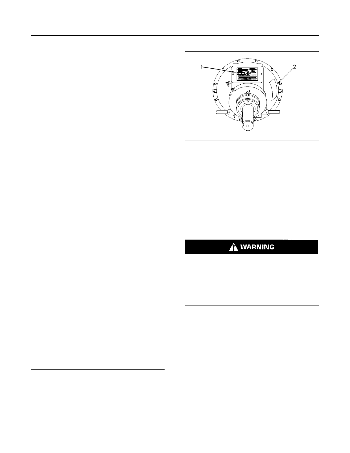
SEBU9072 79
Maintenance Recommendations
Overhaul Considerations
3. Drain the coolant from the cooling system to a level
that is below the hose that is being replaced.
4. Remove the hose clamps.
5. Disconnect the old hose.
6. Replace the old hose with a new hose.
7. Install the hose clamps with a torque wrench.
Note: For the correct coolant, see this Operation and
Maintenance Manual, “Fluid Recommendations”.
8. Refill the cooling system. Refer to the OEM
information for further information on refilling the
cooling system.
9. Clean the cooling system filler cap. Inspect the
cooling system filler caps seals. Replace the
cooling system filler cap if the seals are damaged.
Install the cooling system filler cap.
10. Start the engine. Inspect the cooling system for
leaks.
Fuel System
The fuel system is split into two different sections,
high pressure, and low pressure. Ensure that the fuel
pressure has been purged before any parts are
removed loosened or replaced.
Illustration 46 g00781502
(1) Instruction plate
(2) Serial number plate
Check the clutch adjustment regularly after “wear in”.
Heavy-duty applications which have engagements
that are frequent and relatively long periods of clutch
slippage require more frequent adjustment than lightduty applications. The operating torque should be
measured in order to determine if a clutch adjustment
is required.
Refer to the OEM information and instruction plate (1)
for instructions on lubrication, adjustment, and other
recommendations for service. Perform the
maintenance that is specified on the instruction plate.
Check that connections and hoses are secure, check
for leaks. If parts are to be removed or tightened, refer
to the Disassembly and Assembly manual for more
information.
i05971077
Overhaul Considerations
For an overhaul solution, contact your Perkins
distributor.
i03901481
Power Take-Off Clutch - Check
NOTICE
New power take-offs should have the clutch adjustment checked before being placed into service. The
clutch adjustment should be checked again after the
first ten hours of operation. New clutch plates have a
“wear in” period, and the clutch may require several
adjustments until the new plates are “worn in”.
Do not operate the engine with the Instruction
Plate cover removed from the clutch. Personal injury may result.
If the clutch is damaged to the point of burst failure, expelled pieces can cause personal injury to
anyone in the immediate area. Proper safeguards
must be followed to help prevent accidents.
i04020194
Radiator - Clean
Note: Adjust the frequency of cleaning according to
the effects of the operating environment.
Inspect the radiator for these items: damaged fins,
corrosion, dirt, grease, insects, leaves, oil and other
debris. Clean the radiator, if necessary.
Page 80

80 SEBU9072
Maintenance Recommendations
Starting Motor - Inspect
i06120055
Personal injury can result from air pressure.
Personal injury can result without following proper procedure. When using pressure air, wear a
protective face shield and protective clothing.
The maximum air pressure for cleaning purposes
must be reduced to 205 kPa (30 psi) when the air
nozzle is deadheaded.
Pressurized air is the preferred method for removing
loose debris. Direct the air in the opposite direction of
the air flow. Hold the nozzle approximately 6 mm
(0.25 inch) away from the fins. Slowly move the air
nozzle in a direction that is parallel with the tubes.
This movement will remove debris that is between the
tubes.
Pressurized water may also be used for cleaning. The
maximum water pressure for cleaning purposes must
be less than 275 kPa (40 psi). Use pressurized water
in order to soften mud. Clean the core from both
sides.
Use a degreaser and steam for removal of oil and
grease. Clean both sides of the core. Wash the core
with detergent and hot water. Thoroughly rinse the
core with clean water.
After cleaning, start the engine and accelerate the
engine to high idle rpm. This procedure will help in the
removal of debris and drying of the core. Stop the
engine. Use a light bulb behind the core in order to
inspect the core for cleanliness. Repeat the cleaning,
if necessary.
Inspect the fins for damage. Bent fins may be opened
with a “comb”. Inspect these items for good condition:
welds, mounting brackets, air lines, connections,
clamps and seals. Make repairs, if necessary.
Walk-Around Inspection
Inspect the Engine for Leaks and
for Loose Connections
A walk-around inspection should only take a few
minutes. When the time is taken to perform these
checks, costly repairs and accidents can be avoided.
For maximum engine service life, make a thorough
inspection of the engine compartment before starting
the engine. Look for items such as oil leaks or coolant
leaks, loose bolts, worn belts, loose connections, and
trash buildup. Make repairs, as needed:
• The guards must be in the proper place. Repair
damaged guards or replace missing guards.
• Wipe all caps and plugs before the engine is
serviced in order to reduce the chance of system
contamination.
NOTICE
For any type of leak (coolant, lube, or fuel) clean up
the fluid. If leaking is observed, find the source and
correct the leak. If leaking is suspected, check the fluid levels more often than recommended until the leak
is found or fixed, or until the suspicion of a leak is
proved to be unwarranted.
NOTICE
Accumulated grease and/or oil on an engine or deck
is a fire hazard. Remove this debris with steam cleaning or high pressure water.
i02568202
Starting Motor - Inspect
Perkins recommends a scheduled inspection of the
starting motor. If the starting motor fails, the engine
may not start in an emergency situation.
Check the starting motor for proper operation. Check
the electrical connections and clean the electrical
connections. Refer to the Service Manual for more
information on the checking procedure and for
specifications or consult your Perkins distributors for
assistance.
• Ensure that the cooling lines are properly clamped
and that the cooling lines are tight. Check for
leaks. Check the condition of all pipes.
• Inspect the water pumps for coolant leaks.
Note: The water pump seal is lubricated by coolant in
the cooling system. It is normal for a small amount of
leakage to occur as the engine cools down and the
parts contract.
Excessive coolant leakage may indicate the need to
replace the water pump seal. For the removal of
water pumps and the installation of water pumps and/
or seals, refer to the Service Manual for the engine or
consult your Perkins distributor .
Page 81

SEBU9072 81
Maintenance Recommendations
Walk-Around Inspection
• Inspect the lubrication system for leaks at the front
crankshaft seal, the rear crankshaft seal, the oil
pan, the oil filters, and the valve cover.
• Inspect the fuel system for leaks. Look for loose
fuel line clamps or for loose fuel line tie-wraps.
• Inspect the piping for the air inlet system and the
elbows for cracks and for loose clamps. Ensure
that hoses and tubes are not contacting other
hoses, tubes, and wiring harnesses.
• Inspect the alternator belt and the accessory drive
belts for cracks, breaks, or other damage.
Belts for multiple groove pulleys must be replaced as
matched sets. If only one belt is replaced, the belt will
carry more load than the belts that are not replaced.
The older belts are stretched. The additional load on
the new belt could cause the belt to break.
• Drain the water and the sediment from fuel tanks
on a daily basis in order to ensure that only clean
fuel enters the fuel system.
• Drain the water from the primary fuel filter.
• Inspect the wiring and the wiring harnesses for
loose connections and for worn wires or frayed
wires.
• Inspect the ground strap for a good connection
and for good condition.
• Inspect the ECM to the cylinder head ground strap
for a good connection and for good condition.
• Disconnect any battery chargers that are not
protected against the current drain of the starting
motor. Check the condition and the electrolyte
level of the batteries, unless the engine is
equipped with a maintenance free battery.
• Check the condition of the gauges. Replace any
gauges that are cracked. Replace any gauge that
cannot be calibrated.
Page 82

82 SEBU9072
Warranty Section
Emissions Warranty Information
Warranty Section
Warranty Information
i05680169
Emissions Warranty
Information
The certifying engine manufacturer warrants to the
ultimate purchaser and each subsequent purchaser
that:
1. New non-road diesel engines and stationary diesel
engines less than 10 L per cylinder (including Tier
1 and Tier 2 marine engines < 37 kW, but
excluding locomotive and other marine engines)
operated and serviced in the United States and
Canada, including all parts of their emission control
systems (“emission related components”), are:
a. Designed, built, and equipped so as to
conform, at the time of sale, with applicable
emission standards prescribed by the United
States Environmental Protection Agency
(EPA) by way of regulation.
The aftertreatment system can be expected to
function properly for the lifetime of the engine
(emissions durability period) subject to prescribed
maintenance requirements being followed.
A detailed explanation of the Emission Control
Warranty is available to view on Perkins. com service
and support.
b. Free from defects in materials and
workmanship in emission-related components
that can cause the engine to fail to conform to
applicable emission standards for the warranty
period.
2. New non-road diesel engines (including Tier 1 and
Tier 2 marine propulsion engines < 37 kW and Tier
1 through Tier 4 marine auxiliary engines < 37 kW,
but excluding locomotive and other marine
engines) operated and serviced in the state of
California, including all parts of their emission
control systems (“emission related components”),
are:
a. Designed, built, and equipped so as to
conform, at the time of sale, to all applicable
regulations adopted by the California Air
Resources Board (ARB).
b. Free from defects in materials and
workmanship which cause the failure of an
emission-related component to be identical in
all material respects to the component as
described in the engine manufacturer's
application for certification for the warranty
period.
Page 83

SEBU9072 83
Reference Information Section
Maintenance Records
Reference Information
Section
Reference Materials
i05204672
Maintenance Records
Perkins recommends the retention of accurate
maintenance records. Accurate maintenance records
can be used for the following purposes:
• Determine operating costs.
• Establish maintenance schedules for other
engines that are operated in the same
environment.
• Show compliance with the required maintenance
practices and maintenance intervals.
Maintenance records can be used for various other
business decisions that are related to engine
maintenance.
• Dealer work orders and itemized bills
• Owners repair costs
• Owners receipts
• Maintenance log
Maintenance records are a key element of a
maintenance program that is correctly managed.
Accurate maintenance records can help your Perkins
dealer to fine-tune the recommended maintenance
intervals in order to meet the specific operating
situation. This should result in a lower engine
operating cost.
Records should be kept for the following items:
Fuel Consumption – A record of fuel consumption is
essential in order to determine when the load
sensitive components should be inspected or
repaired. Fuel consumption also determines overhaul
intervals.
Service Hours – A record of service hours is
essential to determine when the speed sensitive
components should be inspected or repaired.
Documents – These items should be easy to obtain,
and these items should be kept in the engine history
file. All of the documents should show this
information: date, service hours, fuel consumption,
unit number and engine serial number. The following
types of documents should be kept as proof of
maintenance or repair for warranty:
Keep the following types of documents as proof of
maintenance for warranty. Also, keep these types of
documents as proof of repair for warranty:
Page 84

84 SEBU9072
Reference Materials
Maintenance Log
i05204675
Maintenance Log
Table 14
Engine Model Customer Identifier
Serial Number
Service
Hours
Quantity Of
Fuel
Arrangement Number
Service Item Date Authorization
Page 85

SEBU9072 85
Reference Materials
Reference Material
i05204677
Reference Material
(Extended Service Contract)
Extended Service Contracts-purchased in minutes,
protected for years.
Extended Service Contracts (ESC) protect you from
the stress that unexpected repair work brings to your
life bt covering the cost of getting your engine up and
running again. Unlike other extended warranties,
Perkins Platinum ESC protects you against all
component part failures.
Purchase peace of mine from only £0.03 / $0.05 /
euro 0.04 a day and let an ESC make your dreams a
reality.
Why buy an Extended Service Contract?
1. No surprises - total protection from unexpected
repair cost (parts, labor, and travel).
2. Enjoy longer lasting product support from Perkins
global network.
i06103116
Decommissioning and
Disposal
When the product is removed from service, local
regulations for the product decommissioning will vary.
Disposal of the product will vary with local
regulations. Consult the nearest Perkins distributor
for additional information.
3. Genuine Perkins parts ensure continued engine
performance.
4. Highly trained technicians carry out all repairs.
5. Transferable coverage should you sell your
machine.
Flexible coverage provides the right level of
protection for your Perkins Engine. Coverage can be
extended to 2 years/ 1,000 hours right up to 10 year/
40,000
You can buy an ESC at any time during standard
warranty - even the last day!
Each Perkins Distributor has highly trained and
experienced Perkins Product Support Service
Technicians. The Support Service are equipped, and
available around the clock to get your engine running
again with the minimum of downtime. Buying an ESC
means that you get all this for free.
To purchase an Extended Service Contract, is quick
and simple! Contact your local Perkins Distributor
now and the distributor can provide you with a quote
in minutes. You can locate your nearest Perkins
Distributor by visiting:
www.perkins.com
NOTICE
Dependant upon engine type and application.
Page 86

86 SEBU9072
Index Section
Index
A
After Starting Engine........................................ 33
Extended Idle at Cold Ambient Temperature
................................................................... 33
After Stopping Engine...................................... 38
Air Compressor - Check (If Equipped)............. 57
Air Shutoff - Test .............................................. 58
Air Tank Moisture and Sediment - Drain (If
Equipped) ...................................................... 58
B
Battery - Recycle ............................................. 59
Battery - Replace............................................. 59
Battery Disconnect Switch (If Equipped) ......... 23
Battery Electrolyte Level - Check .................... 60
Battery or Battery Cable - Disconnect ............. 60
Before Starting Engine ...............................12, 30
Belts - Inspect/Replace (Multi Vee Belt) .......... 60
Burn Prevention............................................... 10
Batteries....................................................... 10
Coolant......................................................... 10
Diesel Fuel ................................................... 10
Oils............................................................... 10
C
Cold Weather Operation.................................. 36
Cold Weather Starting ..................................... 30
Ether Injection System (If Equipped) ........... 31
Configuration Parameters................................ 28
System Configuration Parameters............... 29
Coolant (DEAC) - Change ............................... 61
Drain ............................................................ 61
Fill................................................................. 62
Flush ............................................................ 61
Coolant (ELC) - Change .................................. 62
Drain ............................................................ 63
Fill................................................................. 63
Flush ............................................................ 63
Coolant Extender (ELC) - Add......................... 64
Coolant Level - Check ..................................... 64
Cooling System Supplemental Coolant
Additive (SCA) - Test/Add .............................. 64
Add the SCA, If Necessary .......................... 65
Test for SCA Concentration ......................... 64
Crushing Prevention and Cutting Prevention .. 12
D
Decommissioning and Disposal ...................... 85
Diagnostic Lamp.............................................. 28
Driven Equipment - Check............................... 65
E
Electrical System............................................. 13
Grounding Practices .................................... 13
Emissions Certification Film ............................ 18
Emissions Warranty Information...................... 82
Engaging the Driven Equipment...................... 34
Engine - Clean................................................. 65
Engine Air Cleaner Element (Dual Element)
- Inspect/Clean/Replace ................................ 66
Cleaning the Primary Air Cleaner Elements
................................................................... 67
Servicing the Air Cleaner Elements ............. 66
Engine Air Cleaner Element (Single
Element) - Inspect/Clean/Replace................. 68
Engine Air Cleaner Service Indicator -
Inspect (If Equipped)...................................... 69
Test the Service Indicator............................. 69
Engine Crankcase Breather - Clean................ 69
Engine Diagnostics.......................................... 28
Engine Electronics........................................... 14
Engine Mounts - Inspect.................................. 70
Engine Oil and Filter - Change ........................ 71
Drain the Engine Lubricating Oil .................. 72
Fill the Oil Pan.............................................. 72
Engine Oil Level - Check ................................. 70
Engine Oil Sample - Obtain ............................. 71
Obtain the Sample and the Analysis............ 71
Engine Operation............................................. 34
Variable Speed Engine ................................ 34
Engine Operation with Active Diagnostic
Codes ............................................................ 28
Engine Operation with Intermittent
Diagnostic Codes........................................... 29
Engine Starting...........................................13, 30
Engine Stopping .........................................13, 38
Engine Valve Lash - Check.............................. 73
F
Fault Logging................................................... 28
Features and Controls..................................... 23
Page 87

SEBU9072 87
Index Section
Fire Prevention and Explosion Prevention ...... 10
Ether .............................................................11
Fire Extinguisher...........................................11
Lines, Tubes, and Hoses ............................. 12
Fluid Recommendations.............................39, 52
ELC Cooling System Maintenance.............. 42
Engine Oil .................................................... 52
General Coolant Information........................ 39
General Lubricant Information ..................... 52
Fluid Recommendations (Fuel
Recommendations) ....................................... 44
Contamination Control Recommendations for
Fuels .......................................................... 51
Diesel Fuel Characteristics.......................... 46
Diesel Fuel Requirements............................ 44
General Information..................................... 44
Foreword............................................................ 4
California Proposition 65 Warning ................. 4
Literature Information..................................... 4
Maintenance .................................................. 4
Maintenance Intervals.................................... 4
Operation ....................................................... 4
Overhaul ........................................................ 4
Safety............................................................. 4
Fuel and the Effect from Cold Weather............ 36
Fuel Conservation Practices............................ 34
Fuel Related Components in Cold Weather .... 36
Fuel Heaters ................................................ 37
Fuel Tanks.................................................... 36
Fuel System - Prime ........................................ 73
Fuel System Primary Filter (Water
Separator) Element - Replace ....................... 74
Fuel System Primary Filter/Water Separator
- Drain ............................................................ 75
Fuel System Secondary Filter - Replace......... 76
Fuel Tank Water and Sediment - Drain............ 77
Drain the Water and the Sediment............... 77
Fuel Storage Tanks ...................................... 77
Fuel Tank ..................................................... 77
G
General Hazard Information .............................. 6
Containing Fluid Spillage............................... 8
Dispose of Waste Properly............................. 9
Fluid Penetration............................................ 8
Inhalation ....................................................... 9
Pressurized Air and Water............................. 8
Static Electricity Hazard when Fueling with
Ultra-low Sulfur Diesel Fuel.......................... 8
General Information......................................... 15
Grounding Stud - Inspect/Clean/Tighten ......... 77
H
Hoses and Clamps - Inspect/Replace ............. 78
Fuel System ................................................. 79
Replace the Hoses and the Clamps ............ 78
I
Important Safety Information ............................. 2
L
Lifting and Storage........................................... 20
M
Maintenance Interval Schedule ....................... 57
Daily ............................................................. 57
Every 10 000 Service Hours ........................ 57
Every 12 000 Service Hours or 6 Years ....... 57
Every 2000 Service Hours ........................... 57
Every 2000 Service Hours or 1 Year............ 57
Every 250 Service Hours ............................. 57
Every 2500 Service Hours ........................... 57
Every 3000 Service Hours or 2 Years.......... 57
Every 4000 Service Hours ........................... 57
Every 500 Service Hours ............................. 57
Every 500 Service Hours or 1 Year.............. 57
Every 6000 Service Hours or 3 Years.......... 57
Initial 500 Service Hours .............................. 57
When Required............................................ 57
Maintenance Log ............................................. 84
Maintenance Recommendations..................... 54
Maintenance Records...................................... 83
Maintenance Section ....................................... 39
Manual Stop Procedure................................... 38
Model View Illustrations................................... 15
Monitoring System........................................... 23
Action Alert................................................... 24
Critical Protection Override .......................... 24
Diagnostic .................................................... 25
Shutdown..................................................... 24
Shutdown Reset........................................... 25
Standard Warning Outputs .......................... 24
Warning Alarm ............................................. 24
Mounting and Dismounting.............................. 12
Page 88

88 SEBU9072
Index Section
O
Operation Section............................................ 20
Overhaul Considerations................................. 79
P
Plate Locations and Film Locations................. 18
Power Take-Off Clutch - Check ....................... 79
Product Description ......................................... 16
Aftermarket Products and Perkins Engines
................................................................... 17
Electronic Engine Features.......................... 17
Engine Service Life...................................... 17
Engine Specifications .................................. 16
Product Identification Information.................... 18
Product Information Section ............................ 15
Product Lifting.................................................. 20
Product Storage............................................... 20
Engine.......................................................... 20
R
Starting with Jump Start Cables (Do Not Use
This Procedure in Hazardous Locations that
have Explosive Atmospheres)....................... 32
Stopping the Engine ........................................ 38
System Pressure Release............................... 54
Coolant System............................................ 54
Engine Oil .................................................... 54
Fuel System ................................................. 54
T
Table of Contents............................................... 3
W
Walk-Around Inspection .................................. 80
Inspect the Engine for Leaks and for Loose
Connections............................................... 80
Warranty Information ....................................... 82
Warranty Section ............................................. 82
Welding on Engines with Electronic Controls.. 54
Radiator - Clean............................................... 79
Radiator Restrictions ....................................... 36
Reference Information ..................................... 18
Record for Reference................................... 19
Reference Information Section ........................ 83
Reference Material (Extended Service
Contract)........................................................ 85
Reference Materials ........................................ 83
Refill Capacities............................................... 39
Coolant Refill Capacity................................. 39
Lubricant Refill Capacity .............................. 39
S
Safety Messages............................................... 5
Universal Warning (1) .................................... 6
Safety Section ................................................... 5
Self-Diagnostics............................................... 28
Sensors and Electrical Components ............... 25
Severe Service Application.............................. 56
Environmental Factors................................. 56
Incorrect Maintenance Procedures.............. 56
Incorrect Operating Procedures................... 56
Starting Motor - Inspect ................................... 80
Starting the Engine.......................................... 31
Problems with the Wiring Harness............... 32
Starting Problems ........................................ 32
Starting the Engine ...................................... 31
Page 89

Product and Dealer Information
Note: For
product identification plate locations, see the section “Product Identification
Information” in the Operation and Maintenance Manual.
Delivery Date:
Product Information
Model:
Product Identification Number:
Engine Serial Number:
Transmission
Serial Number:
Generator Serial Number:
Attachment Serial Numbers:
Attachment Information:
Customer Equipment Number:
Dealer Equipment
Number:
Dealer Information
Name: Branch:
Address:
Dealer
Contact
Sales:
Phone
Number
Hours
Parts:
Service:
Page 90

©2015 Perkins Engines Compony Limited
All Rights Reserved
 Loading...