

Page 1

Operation and
Maintenance
Manual
SEBU8119-02
January 2008
1106D Industrial Engine
(Engine)
PJ
Page 2

Important Safety Information
Most accidents that involve product operation, maintenance and repair are caused by failure to
observe basic safety rules or precautions. An accident can often be avoided by recognizing potentially
hazardous situations before an accident occurs. A person must be alert to potential hazards. This
person should also have the necessary training, skills and tools to perform these functions properly.
Improper operation, lubrication, maintenance or repair of this product can be dangerous and
could result in injury or death.
Do not operate or perform any lubrication, maintenance or repair on this product, until you have
read and understood the operation, lubrication, maintenance and repair information.
Safety precautions and warnings are provided in this manual and on the product. If these hazard
warnings are not heeded, bodily injury or death could occur to you or to other persons.
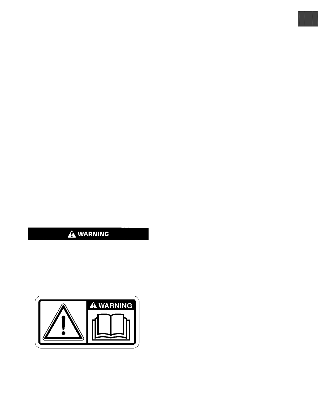
The hazards are identified by the “Safety Alert Symbol” and followed by a “Signal Word” such as
“DANGER”, “WARNING” or “CAUTION”. The Safety Alert “WARNING” label is shown below.
The meaning of this safety alert symbol is as follows:
Attention! Become Alert! Your Safety is Involved.
The message that appears under the warning explains the hazard and can be either written or
pictorially presented.
Operations that may cause product damage are identified by “NOTICE” labels on the product and in
this publication.
Perkins cannot anticipate every possible circumstance that might involve a potential hazard. The
warnings in this publication and on the product are, therefore, not all inclusive. If a tool, procedure,
work method or operating technique that is not specifically recommended by Perkins is used,
you must satisfy yourself that it is safe for you and for others. You should also ensure that the
product will not be damaged or be made unsafe by the operation, lubrication, maintenance or
repair procedures that you choose.
The information, specifications, and illustrations in this publication are on the basis of information that
was available at the time that the publication was written. The specifications, torques, pressures,
measurements, adjustments, illustrations, and other items can change at any time. These changes can
affect the service that is given to the product. Obtain the complete and most current information before
you start any job. Perkins dealers or Perkins distributors have the most current information available.
When replacement parts are required for this
product Perkins recommends using Perkins
replacement parts.
Failure to heed this warning can lead to premature failures, product damage, personal injury or
death.
Page 3

SEBU8119-02 3
Table of Contents
Table of Contents
Foreword ................................................................. 4
Safety Section
Safety Messages .................................................... 5
General Hazard Information ................................... 7
Burn Prevention ...................................................... 9
Fire Prevention and Explosion Prevention .............. 9
Crushing Prevention and Cutting Prevention ......... 11
Mounting and Dismounting .................................... 11
High Pressure Fuel Lines ..................................... 12
Before Starting Engine .......................................... 13
Engine Starting ..................................................... 13
Engine Stopping ................................................... 14
Maintenance In
Warranty S ecti
Warranty Information .......................................... 100
terval Schedule ............................ 65
on
Index Section
Index ................................................................... 101
Electrical System .................................................. 14
Engine Electronics ................................................ 15
Product Information Section
General Information .............................................. 17
Model Views ......................................................... 18
Product Identification Information ........................ 22
Operation Section
Lifting and Storage ................................................ 24
Gauges and Indicators .............................. ............ 26
Features and Controls .......................................... 28
Engine Diagnostics ............................................... 35
Engine Starting ..................................................... 39
Engine Operation .................................................. 42
Engine Stopping ................................................... 43
Cold Weather Operation ....................................... 45
Maintenance Section
Refill Capacities .................................................... 49
Page 4

4 SEBU8119-02
Foreword
Foreword
Literature Information
This manual con
lubrication and maintenance information. This
manual should be stored in or near the engine area
in a literatur
study and keep it with the literature and engine
information.
English is the primary language for all Perkins
publications. The English used facilitates translation
and consiste
Some photographs or illustrations in this manual
show details
from your engine. Guards and covers may have
been removed for illustrative purposes. Continuing
improvemen
may have caused changes to your engine which are
not included in this manual. Whenever a question
arises reg
consult with your Perkins dealer or your Perkins
distributor for the latest available information.
Safety
This safety section lists basic safety precautions.
In addition, this section identifies hazardous,
warning si
precautions listed in the safety section before
operating or performing lubrication, maintenance and
repair on
this product.
tains safety, operation instructions,
e holder or literature storage area. Read,
ncy.
or attachments that may be different
t and advancement of product design
arding your engine, or this manual, please
tuations. Read and understand the basic
Recommended se
appropriate intervals as indicated in the Maintenance
Interval Schedule. The actual operating environment
of the engine a
Schedule. Therefore, under extremely severe,
dusty, wet or freezing cold operating conditions,
more frequen
specified in the Maintenance Interval Schedule may
be necessary.
The maintenance schedule items are organized for
a preventive maintenance management program. If
the prevent
periodic tune-up is not required. The implementation
of a preventive maintenance management program
should mini
avoidances resulting from reductions in unscheduled
downtime and failures.
ive maintenance program is followed, a
mize operating costs through cost
rvice should be performed at the
lso governs the Maintenance Interval
t lubrication and maintenance than is
Maintenance Intervals
Perform maintenance on items at multiples of
the original requirement. We recommend that the
maintenan
near the engine as a convenient reminder. We also
recommend that a maintenance record be maintained
as part of
Your authorized Perkins dealer or your Perkins
distribu
maintenance schedule to meet the needs of your
operating environment.
ce schedules be reproduced and displayed
the engine’s permanent record.
tor can assist you in adjusting your
Overhaul
Operatio
Operating techniques outlined in this manual are
basic. Th
techniques required to operate the engine more
efficiently and economically. Skill and techniques
develop
engine and its capabilities.
The oper
Photographs and illustrations guide the operator
through procedures of inspecting, starting, operating
and sto
discussion of electronic diagnostic information.
n
ey assist with developing the skills and
as the operator gains knowledge of the
ation section is a reference for operators.
pping the engine. This section also includes a
Maintenance
The mai
The illustrated, step-by-step instructions are grouped
by service hours and/or calendar time maintenance
interv
referenced to detailed instructions that follow.
ntenance section is a guide to engine care.
als. Items in the maintenance schedule are
Major engine overhaul details are not covered in
the Operation and Maintenance Manual except
for the i
interval. Major repairs should only be carried out by
Perkins authorized personnel. Your Perkins dealer
or your P
regarding overhaul programs. If you experience
a major engine failure, there are also numerous
after f
your Perkins dealer or your Perkins distributor for
information regarding these options.
nterval and the maintenance items in that
erkins distributor offers a variety of options
ailure overhaul options available. Consult with
California Proposition 65 Warning
Diesel engine exhaust and some of its constituents
are known to the State of California to cause cancer,
defects, and other reproductive harm. Battery
birth
posts, terminals and related accessories contain lead
and lead compounds. Wash hands after handling.
Page 5
SEBU8119-02 5
Safety Section
Safety Messages
Safety Section
i02788195
Safety Messages
There may be s
engine. The exact location and a description of the
warning signs are reviewed in this section. Please
become famil
Ensure that all of the warning signs are legible. Clean
the warning s
the words cannot be read or if the illustrations are
not visible. Use a cloth, water, and soap to clean
the warning
other harsh chemicals. Solvents, gasoline, or harsh
chemicals could loosen the adhesive that secures the
warning si
could drop off of the engine.
Replace an
missing.Ifawarningsignisattachedtoapartofthe
engine that is replaced, install a new warning sign on
the replac
provide new warning signs.
everal specific warning signs on your
iar with all warning signs.
igns or replace the warning signs if
signs. Do not use solvents, gasoline, or
gns. The warning signs that are loosened
y warning sign that is damaged or
ement part. Your Perkins distributor can
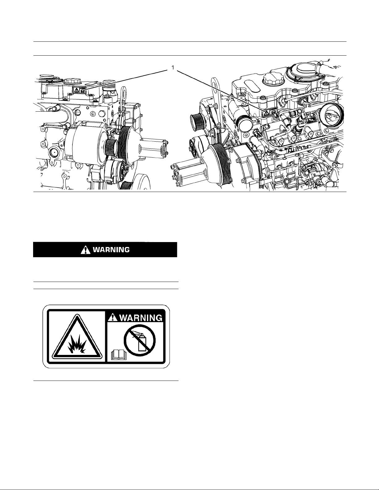
(1) Un iversal Warning
Do not operate or work on this equipment unless
you have r
and warnings in the Operation and Maintenance
Manuals. Failure to follow the instructions or
heed the
or death.
ead and understand the instructions
warnings could result in serious injury
Illustration 1
lexample
Typica
The Universal Warning label (1) is located on both
sides o
f the valve mechanism cover base.
g01154807
Page 6
6 SEBU8119-02
Safety Section
Safety Messages
Illustration 2
Location of label
(1) Universal warning
(2) Ether Warning
Do not use aerosol types of starting aids such as
ether. Such use could result in an explosion and
personal injury.
g01392790
Illustration 3
Typical examp le
g01154809
The ether warning label (2) is located on the cover
of the inlet manifold.
Page 7
SEBU8119-02 7
Safety Section
General Hazard Information
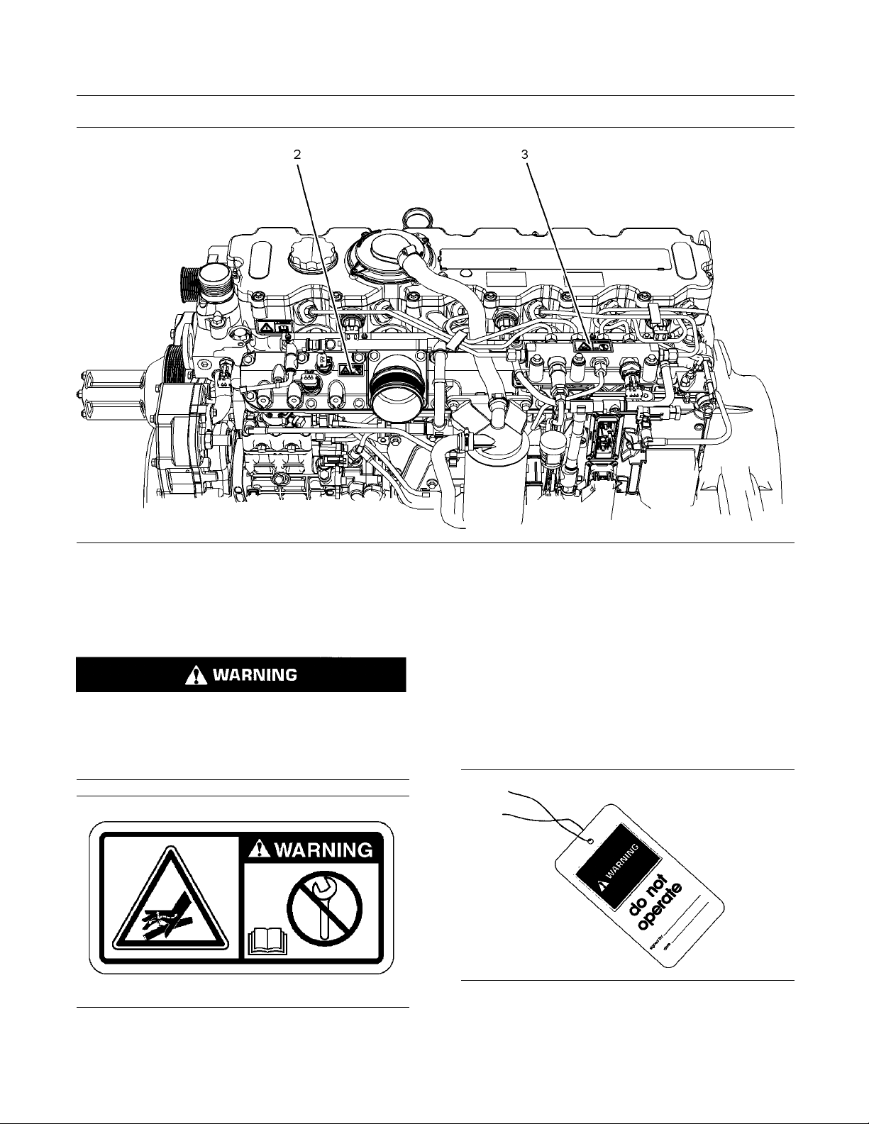
Illustration 4
Location o
(2) Ether (3) Hand (High Pressure)
f labels
(3) Hand (High Pressure)
Contact
penetration and burn hazards. High pressure fuel spray may cause a fire hazard. Failure to follow thes
structions may cause personal injury or death.
with high pressure fuel may cause fluid
e inspection, maintenance and service in-
g01392789
The warning label for the Hand (High Pressure) (3) is
located o
n the top of the fuel manifold.
i023284
General Hazard Information
35
Illustration 5
lexample
Typica
g01154858
Illustration 6
g0010
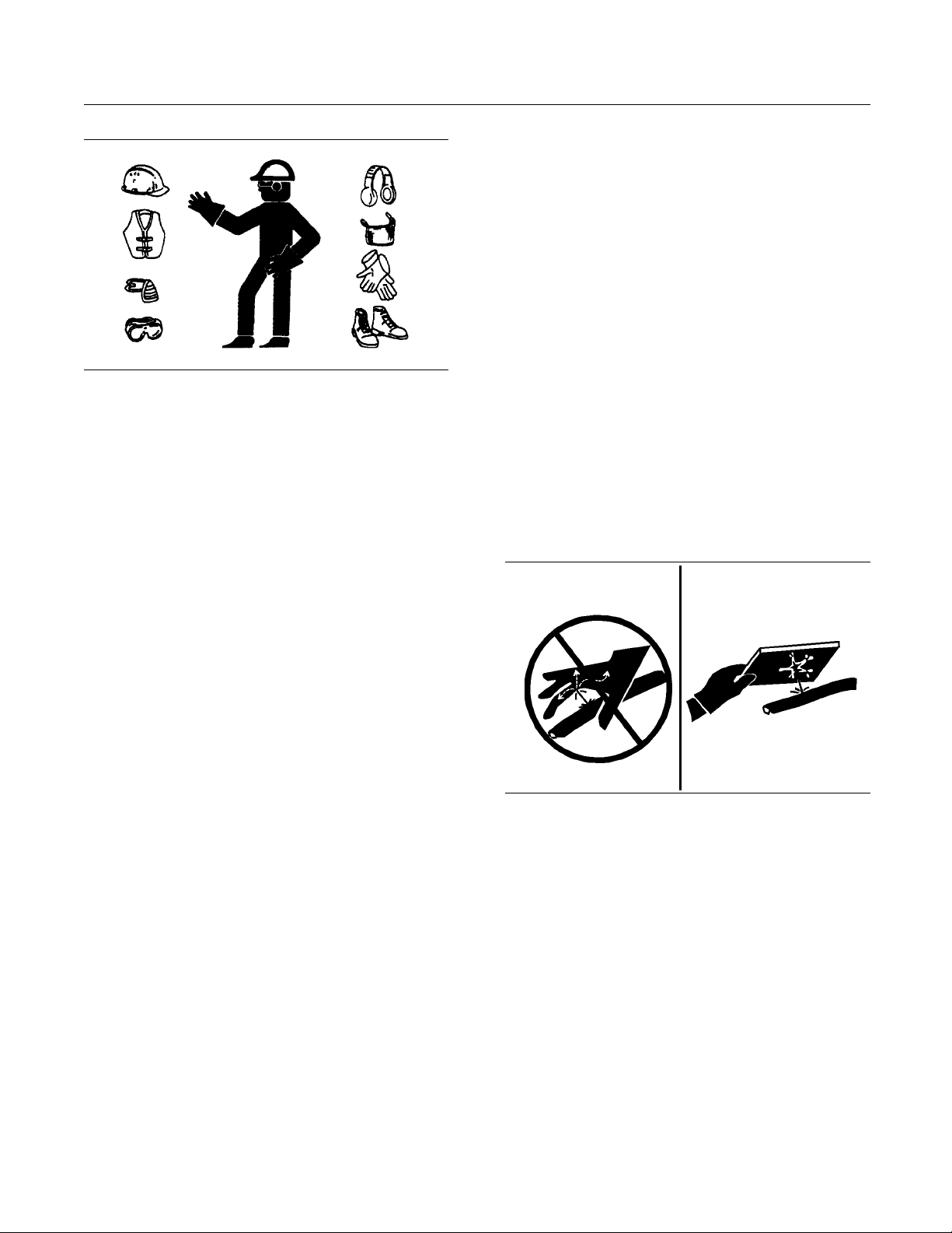
Attach a “Do Not Operate” warning tag or a similar
warning tag to the start switch or to the controls
e you service the equipment or before you
befor
repair the equipment.
4545
Page 8
8 SEBU8119-02
Safety Section
General Hazard Information
Illustration 7
Wear a hard hat, protective glasses, and other
protective equipment, as required.
Do not wear loose clothing or jewelry that can snag
on controls or on other parts of the engine.
Make sure that all protective guards and all covers
are secured in place on the engine.
Keep the engine free from foreign material. Remove
debris, oil, tools, and other items from the deck, from
walkways, and from steps.
g00702020
When pressuriz
cleaning, wear protective clothing, protective shoes,
and eye protection. Eye protection includes goggles
or a protectiv
The maximum air pressure for cleaning purposes
must be below
water pressure for cleaning purposes must be below
275 kPa (40 psi).
ed air and/or water is used for
efaceshield.
205 kPa (30 psi). The maximum
Fluid Penetration
Pressure can be trapped in the hydraulic circuit long
after the engine has been stopped. The pressure can
cause hydrau
escape rapidly if the pressure is not relieved correctly.
Do not remove
until pressure has been relieved or personal injury
may occur. Do not disassemble any hydraulic
components
or personal injury may occur. Refer to the OEM
information for any procedures that are required to
relieve th
lic fluid or items such as pipe plugs to
any hydraulic components or parts
or parts until pressure has been relieved
e hydraulic pressure.
Never put maintenance fluids into glass containers.
Drain all liquids into a suitable container.
Obey all local regulations for the disposal of liquids.
Use all cleaning solutions with care.
Report all necessary repairs.
Do not allow unauthorized personnel on the
equipment.
Ensure that the power supply is disconnected before
you work on the bus bar or the glow plugs.
Perform maintenance on the engine with the
equipment in the servicing position. Refer to the
OEM information for the procedure for placing the
equipment in the servicing position.
Pressure Air and Water
Pressurized air and/or water can cause debris
and/or hot water to be blown out. This could result in
personal injury.
The direct application of pressurized air or
pressurized water to the body could result in personal
injury.
Illustration 8
Always use a board or cardboard when you check
for a leak. Leaking fluid that is under pressure can
penetrate body tissue. Fluid penetration can cause
serious injury and possible death. A pin hole leak can
cause severe injury. If fluid is injected into your skin,
you must get treatment immediately. Seek treatment
from a doctor that is familiar with this type of injury.
g00687600
Containing Fluid Spillage
Care must be taken in order to ensure that fluids
are contained during performance of inspection,
maintenance, testing, adjusting and repair of the
engine. Make provision to collect the fluid with a
suitable container before any compartment is opened
or before any component is disassembled.
Only use the tools that are suitable for collecting
•
fluids and equipment that is suitable for collecting
fluids.
Page 9
SEBU8119-02 9
Safety Section
Burn Prevention
Only use the too
•
fluids and equipment that is suitable for containing
fluids.
Obey all local regulations for the disposal of liquids.
ls that are suitable for containing
i02334785
Burn Prevention
Do not touch any part of an operating engine.
Allow the engine to cool before any maintenance is
performed on the engine.
Contact with h igh pressure fuel may cause fluid
penetration and burn hazards. High pressure fuel spray may cause a fire hazard. Failure to follow these inspection, maintenance and service instructions may cause personal injury or death.
After the engine has stopped, you must wait for 60
seconds in order to allow the fuel pressure to be
purged from the high pressure fuel lines before any
service or repair is performed on the engine fuel lines.
Oils
Hot oil and hot lubricating components can cause
personal injury. Do not allow hot oil to contact the
skin. Also, do not allow hot components to contact
the skin.
Batteries
Electrolyte is an acid. Electrolyte can cause personal
injury. Do not allow electrolyte to contact the skin or
the eyes. Always wear protective glasses for servicing
batteries. Wash hands after touching the batteries
and connectors. Use of gloves is recommended.
i02320721
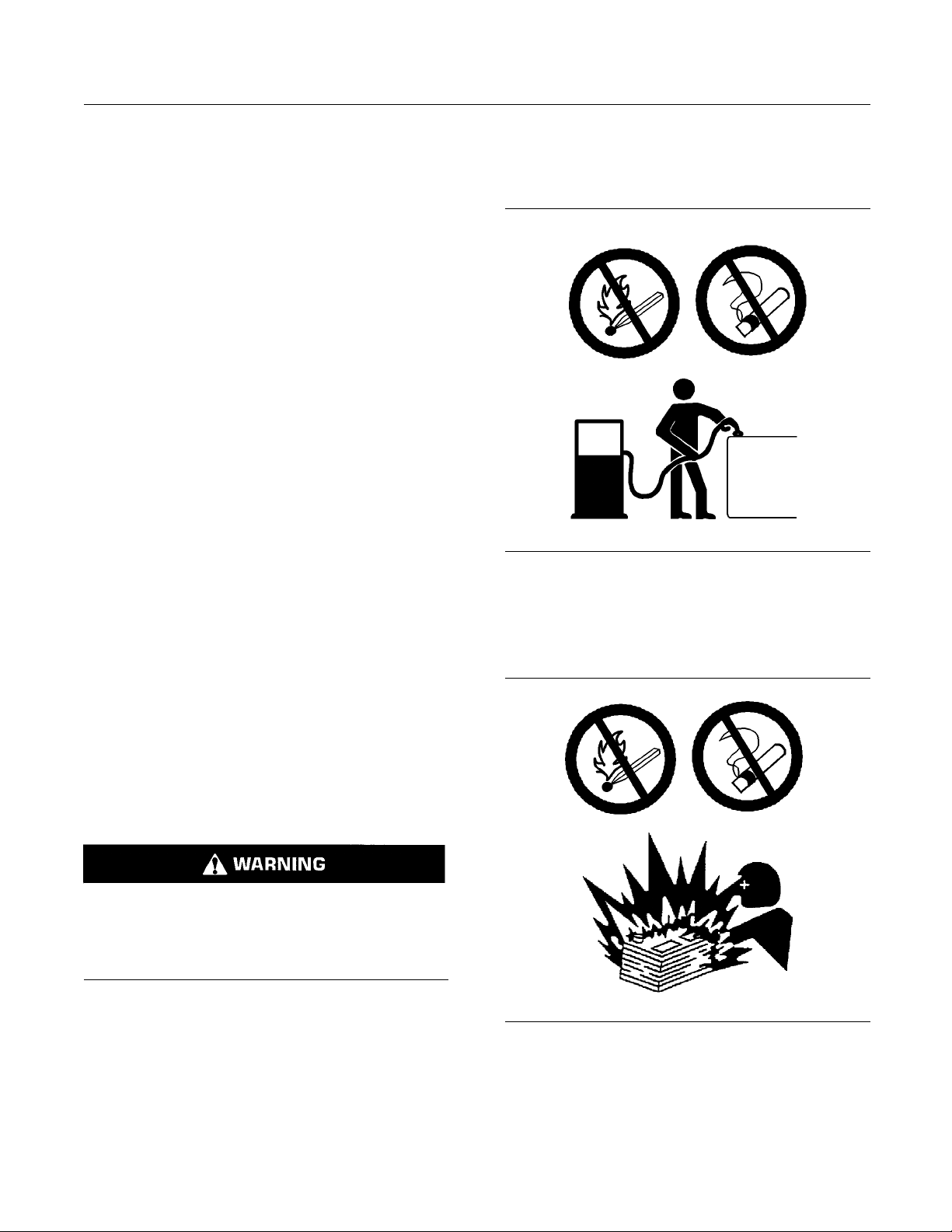
Fire Prevention and Explosion
Prevention
Allow the pressure to be purged in the air system, in
the hydraulic system, in the lubrication system, or in
the cooling system before any lines, fittings or related
items are disconnected.
Coolant
When the engine is at operating temperature, the
engine coolant is hot. The coolant is also under
pressure. The radiator and all lines to the heaters or
to the engine contain hot coolant.
Any contact with hot coolant or with steam can cause
severe burns. Allow cooling system components to
cool before the cooling system is drained.
Check the coolant level after the engine has stopped
and the engine has been allowed to cool.
Ensure that the filler cap is cool before removing the
filler cap. The filler cap must be cool enough to touch
withabarehand.Removethefiller cap slowly in
order to relieve pressure.
Cooling system conditioner contains alkali. Alkali can
cause personal injury. Do not allow alkali to contact
the skin, the eyes, or the mouth.
tion 9
Illustra
All fuels, most lubricants, and some coolant mixtures
are flamma
Flammable fluids that are leaking or spilled onto hot
surfaces
a fire. Fire may cause personal injury and property
damage.
After the emergency stop button is operated ensure
that you allow 15 minutes, before the engine covers
are remo
Determinewhethertheenginewillbeoperatedinan
environ
drawn into the air inlet system. These gases could
cause the engine to overspeed. Personal injury,
proper
If the application involves the presence of combustible
gases,
Perkins distributor for additional information about
suitable protection devices.
ble.
or onto electrical components can cause
ved.
ment that allows combustible gases to be
ty damage, or engine damage could result.
consult your Perkins dealer and/or your
g00704000
Page 10
10 SEBU8119-02
Safety Section
Fire Prevention and Explosion Prevention
Remove all flamm
able combustible materials or
conductive materials such as fuel, oil, and debris from
the engine. Do not allow any flammable combustible
materials or c
onductive materials to accumulate on
the engine.
Store fuels a
nd lubricants in correctly marked
containers away from unauthorized persons. Store
oily rags and any flammable materials in protective
containers.
Do not smoke in areas that are used for
storing flammable materials.
Do not expose
theenginetoanyflame.
Exhaust shields (if equipped) protect hot exhaust
components f
rom oil or fuel spray in case of a line,
a tube, or a seal failure. Exhaust shields must be
installed correctly.
Do not weld on lines or tanks that contain flammable
fluids. Do not flame cut lines or tanks that contain
flammable fl
uid. Clean any such lines or tanks
thoroughly with a nonflammable solvent prior to
welding or fl ame cutting.
Wiring must be kept in good condition. All electrical
wires must be correctly routed and securely attached.
Check all e
lectrical wires daily. Repair any wires
that are loose or frayed before you operate the
engine. Clean all electrical connections and tighten
all elect
rical connections.
Oil filters and f
uel filters must be correctly installed.
The filter housings must be tightened to the correct
torque. Refer to the Disassembly and Assembly
manual for mor
Illustration 10
e information.
g00704059
Use caution when you are refueling an engine. Do
not smoke while you are refueling an engine. Do not
refuel an engine near open flames or sparks. Always
stop the engine before refueling.
Eliminate all wiring that is unattached or unnecessary.
Do not use
any wires or cables that are smaller than
the recommended gauge. Do not bypass any fuses
and/or circuit breakers.
Arcing or sparking could cause a fire. Secure
connections, recommended wiring, and correctly
maintai
ned battery cables will help to prevent arcing
or sparking.
Contact with h igh pressure fuel may cause fluid
penetra
tion and burn hazards. High pressure fuel spray may cause a fire hazard. Failure to follow these inspection, maintenance and service in-
ions may cause personal injury or death.
struct
After the engine has stopped, you must wait for 60
second
s in order to allow the fuel pressure to be
purged from the high pressure fuel lines before any
service or repair is performed on the engine fuel lines.
Ensure that the engine is stopped. Inspect all lines
and hoses for wear or for deterioration. The hoses
must be
correctly routed. The lines and hoses must
have adequate support and secure clamps.
Illustration 11
g00704135
Gases from a battery can explode. Keep any open
flames or sparks away from the top of a battery. Do
not smoke in battery charging areas.
Never check the battery charge by placing a metal
object across the terminal posts. Use a voltmeter or
ahydrometer.
Page 11

SEBU8119-02 11
Safety Section
Crushing Prevention and Cutting Prevention
Incorrect jump
an explosion that can result in injury. Refer to
the Operation Section of this manual for specific
instructions
Do not charge a frozen battery. This may cause an
explosion.
The batteries must be kept clean. The covers
(if equipped
recommended cables, connections, and battery box
covers when the engine is operated.
er cable connections can cause
.
)mustbekeptonthecells.Usethe
Fire Extinguisher
Make sure that a fire extinguisher is available. Be
familiar with the operation of the fire extinguisher.
Inspect the fi
extinguisher regularly. Obey the recommendations
on the instruction plate.
re extinguisher and service the fire
Lines, Tubes and Hoses
Do not bend high pressure lines. Do not strike high
pressure lines. Do not install any lines that are
damaged.
Leaks can cause fires. Consult your Perkins dealer
or your Per
Replace the parts if any of the following conditions
are presen
kins distributor for replacement parts.
t:
i02143194
Crushing Prevention and
Cutting Preve
Support the component correctly when work beneath
the component is performed.
Unless other maintenance instructions are provided,
never attempt adjustments while the engine is
running.
Stay clear of all rotating parts and of all moving
parts. Leave
is performed. After the maintenance is performed,
reinstall the guards.
Keep objects away from moving fan blades. The fan
blades will throw objects or cut objects.
When objects are struck, wear protective glasses in
order to avoid injury to the eyes.
Chips or other debris may fly off objects when objects
are struck. Before objects are struck, ensure that no
one will be i
the guards in place until maintenance
njured by flying debris.
ntion
i02235492
Mounting and Dismounting
High pressure fuel line or lines are removed.
•
End fittings are damaged or leaking.
•
Outer cove
•
Wires are exposed.
•
Outer coverings are ballooning.
•
Flexible p
•
Outer covers have embedded armoring.
•
End fittings are displaced.
•
Make sure t
are installed correctly. During engine operation, this
will help to prevent vibration, rubbing against other
parts, an
rings are chafed or cut.
art of the hoses are kinked.
hat all clamps, guards, and heat shields
d excessive heat.
Inspect the steps, the handholds, and the work area
before mounting the engine. Keep these items clean
and keep these items in good repair.
Mount the engine and dismount the engine only at
locations that have steps and/or handholds. Do not
climb on the engine, and do not jump off the engine.
Face the engine in order to mount the engine or
dismount the engine. Maintain a three-point contact
with the steps and handholds. Use two feet and one
hand or use one foot and two hands. Do not use any
controls as handholds.
Do not stand on components which cannot support
your weight. Use an adequate ladder or use a work
platform. Secure the climbing equipment so that the
equipment will not move.
Do not carry tools or supplies when you mount the
engine or when you dismount the engine. Use a hand
line to raise and lower tools or supplies.
Page 12
12 SEBU8119-02
Safety Section
High Pressure Fuel Lines
i02668808
High Pressure Fuel Lines
Contact with h igh pressure fuel may cause fluid
penetration and burn hazards. High pressure fuel spray may ca
low these inspection, maintenance and service instructions may cause personal injury or death.
use a fire haz ard. Failure to fol-
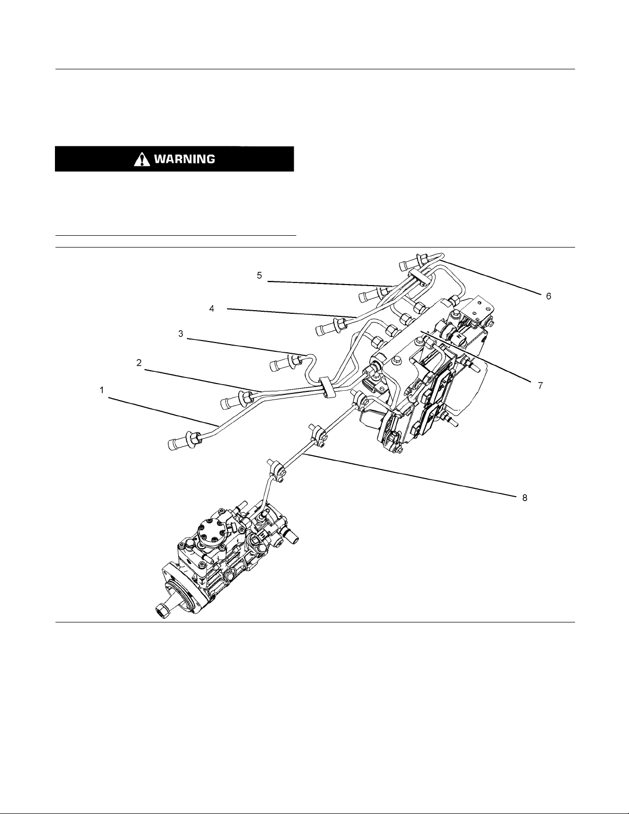
Illustration 1 2
(1)Highpressureline
(2)Highpressureline
(3)Highpressureline
(4) High pressure line
(5) High pressure line
(6) High pressure line
The high pressure fuel lines are the fuel lines that
are between the high pressure fuel pump and the
high pressure fuel manifold and the fuel lines that are
between the fuel manifold and cylinder head. These
fuel lines are different from fuel lines on other fuel
systems.
This is because of the following differences:
g01341328
(7) High pressure fuel manifold (rail)
(8) High pressure line
The high pressure fuel lines are constantly charged
•
with high pressure.
The internal pressures of the high pressure fuel
•
lines are higher than other types of fuel system.
The high pressure fuel lines are formed to shape
•
and then strengthened by a special process.
Page 13

SEBU8119-02 13
Safety Section
Before Starting Engine
Donotsteponth
deflect the high pressure fuel lines. Do not bend or
strike the high pressure fuel lines. Deformation or
damage of the h
point of weakness and potential failure.
Do not check t
engine or the starting motor in operation. After the
engine has stopped allow 60 seconds to pass in order
to allow the p
or repair is performed on the engine fuel lines.
Do not loosen
to remove air from the fuel system. This procedure
is not required.
Visually inspect the high pressure fuel lines before
the engine is started. This inspection should be each
day.
If you inspect the engine in operation, always use
the proper
a fluid penetration hazard. Refer to Operation and
Maintenance Manual, “General hazard Information”.
Inspect the high pressure fuel lines for damage,
•
deformation, a nick, a cut, a crease, or a dent.
Do not operate the engine with a fuel leak. If there
•
isaleakdonottightentheconnectioninorder
to stop the
tightened to the recommended torque. Refer to
Disassembly and Assembly, “Fuel injection lines Remove an
If the high pressure fuel lines are torqued correctly
•
and the hi
high pressure fuel lines must be replaced.
e high pressure fuel lines. Do not
igh pressure fuel lines may cause a
he high pressure fuel lines with the
ressure to be purged before any service
thehighpressurefuellinesinorder
inspection procedure in order to avoid
leak. The connection must only be
d Fuel injection lines - Install”.
gh pressure fuel lines are leaking the
i02813489
Before Starting Engine
Before the init
serviced or repaired, make provision to shut the
engine off, in order to stop an overspeed. This may
be accomplish
supply to the engine.
Overspeed shu
engines that are controlled electronically. If automatic
shutdown does not occur, press the emergency stop
button in ord
Inspect the engine for potential hazards.
Before starting the engine, ensure that no one is on,
underneath, or close to the engine. Ensure that the
area is free
If equipped, ensure that the lighting system for the
engine is su
lights work correctly, if equipped.
All protect
be installed if the engine must be started in order
to perform service procedures. To help prevent an
accident t
around the parts carefully.
Do not bypa
disable the automatic shutoff circuits. The circuits are
provided in order to help prevent personal injury. The
circuits
engine damage.
ialstart-upofanenginethatisnew,
ed by shutting off the air and/or fuel
tdown should occur automatically for
er to cut the fuel and/or air to the engine.
of personnel.
itable for the conditions. Ensure that all
ive guards and all protective covers must
hat is caused by parts in rotation, work
ss the automatic shutoff circuits. Do not
are also provided in order to help prevent
Ensure th
•
are in place. Do not operate the engine with clips
that are damaged, missing or loose.
Do not attach any other item to the high pressure
•
fuel lines.
Loosened high pressure fuel lines must be
•
replaced. Also removed high pressure fuel lines
must be r
assembly manual, “ Fuel Injection Lines - Install”.
at all clips on the high pressure fuel lines
eplaced. Refer to Disassembly and
See the Se
adjustments.
rvice Manual for repairs and for
i02251260
Engine Starting
Do not use aerosol types of starting aids such as
ether. Such use could result in an explosion and
personal injury.
If a warning tag is attached to the engine start switch
or to the controls DO NOT start the engine or move
the controls. Consult with the person that attached
the warning tag before the engine is started.
Page 14

14 SEBU8119-02
Safety Section
Engine Stopping
All protective
be installed if the engine must be started in order
to perform service procedures. To help prevent an
accident that
around the parts carefully.
Start the eng
from the engine start switch.
Always start
that is described in the Operation and Maintenance
Manual, “Engine Starting” topic in the Operation
Section. Kno
prevent major damage to the engine components.
Knowing the procedure will also help to prevent
personal in
To ensure that the jacket water heater (if equipped)
and/or the l
correctly, check the water temperature gauge
and/or the oil temperature gauge during the heater
operation
Engine exhaust contains products of combustion
which can b
engine and operate the engine in a well ventilated
area. If the engine is started in an enclosed area,
vent t he e
Note: The engine is equipped with a device for cold
starting
conditions, then an extra cold starting aid may be
required. Normally, the engine will be equipped with
the corre
operation.
guards and all protective covers must
is caused by parts in rotation, work
ine from the operator’s compartment or
the engine according to the procedure
wing the correct procedure will help to
jury.
ube oil heater (if equipped) is working
.
e harmful to your health. Always start the
ngine exhaust to the outside.
. If the engine will be operated in very cold
ct type of starting aid for your region of
Stop the engine
during the initial start-up of a new engine or an engine
that has been overhauled.
To stop an electronically controlled engine, cut the
power to the engine and/or shutting off the air supply
to the engine
if an overspeed condition occurs
.
i02234878
Electrical System
Never disconnect any charging unit circuit or battery
circuit cable from the battery when the charging unit
is operating. A spark can cause the combustible
gases that are produced by some batteries to ignite.
To help prevent sparks from igniting combustible
gases that are produced by some batteries, the
negative “−” cable should be connected last from the
external power source to the negative “−” terminal
of the starting motor. If the starting motor is not
equipped with a negative “−” terminal, connect the
cabletotheengineblock.
Check the electrical wires daily for wires that
are loose or frayed. Tighten all loose electrical
connections before the engine is started. Repair all
frayed electrical wires before the engine is started.
See the Operation and Maintenance Manual for
specific starting instructions.
These en
aid in each individual cylinder that heats the intake
air in order to improve starting.
ginesareequippedwithaglowplugstarting
i02234873
Engine Stopping
Stop the engine according to the procedure in
the Operation and Maintenance Manual, “Engine
Stopping (Operation Section)” in order to avoid
overheating of the engine and accelerated wear of
the engine components.
Use the Emergency Stop Button (if equipped) ONLY
in an emergency situation. Do not use the Emergency
Stop Button for normal engine stopping. After an
emergency stop, DO NOT start the engine until the
problem that caused the emergency stop has been
corrected.
Page 15
SEBU8119-02 15
Safety Section
Engine Electronics
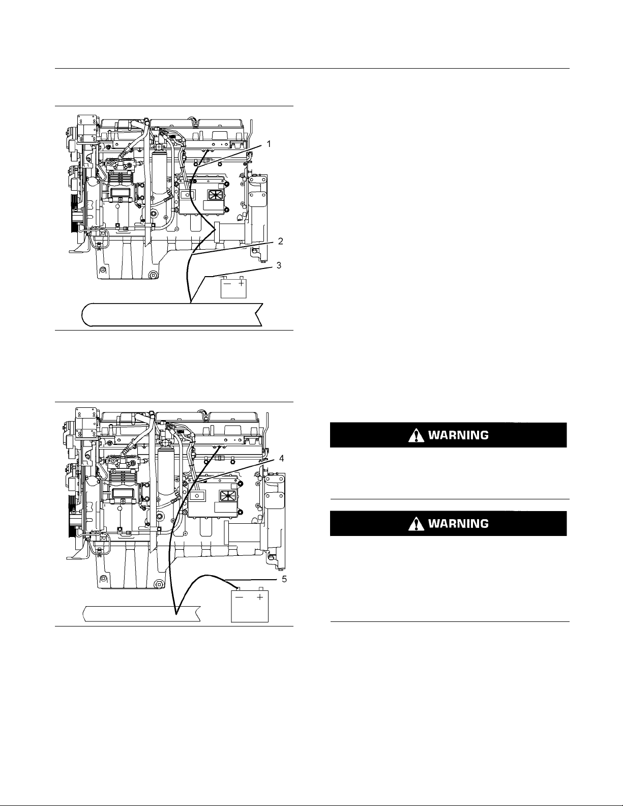
Grounding Practices
Illustration 13
Typical examp le
(1) Starting motor to engine block
(2) Ground to starting motor
(3) Ground to battery
g01162916
Uncontrolled e
lectrical circuit paths can result in
damage to the crankshaft bearing journal surfaces
and to aluminum components.
Engines that are installed without engine-to-frame
ground straps can be damaged by electrical
discharge.
To ensure that the engine and the engine electrical
systems func
tion correctly, an engine-to-frame
ground strap with a direct path to the battery must be
used. This path may be provided by way of a direct
engine groun
d to the frame.
The connections for the grounds should be tight and
free of corro
sion. The engine alternator must be
grounded to the negative “-” battery terminal with
a wire that is adequate to handle the full charging
current of t
he alternator.
The power supply connections and the ground
connectio
ns for the engine electronics should always
be from the isolator to the battery.
i02650954
Engine Electronics
Illustration 14
Typical examp le
(4) Ground to engine
(5) Ground to battery
g01162918
Correct grounding for the engine electrical system
is necessary for optimum engine performance
and reliability. Incorrect grounding will result in
uncontrolled electrical circuit paths and in unreliable
electrical circuit paths.
Tampering
with the electronic system ins tallation
or the OEM wiring installation can be dangerous
and could result in personal injury or death and/or
engine da
mage.
Electrical Shock Hazard. The electronic unit injectors use DC voltage. The ECM sends this voltage
to the electronic unit injectors. Do not come in
contact with the harness connector for the electronic unit injectors while the engine is operating.
Failure to follow this instruction could result in
personal injury or death.
This engine has a comprehensive, programmable
Engine Monitoring System. The Electronic Control
Module (ECM) has the ability to monitor the engine
operating conditions. If any of the engine parameters
extend outside an allowable range, the ECM will
initiate an immediate action.
The following actions are available for engine
monitoring control:
Warning
•
Page 16

16 SEBU8119-02
Safety Section
Engine Electronics
Derate
•
Shutdown
•
The following monitored engine operating conditions
have the ability to limit engine speed and/or the
engine power:
Engine Coolant Temperature
•
Engine Oil Pressure
•
Engine Speed/
•
Intake Manifold Air Temperature
•
The Engine Monitoring package can vary for different
engine models and different engine applications.
However, the m
monitoring control will be similar for all engines.
Note: Many of
modules that are available for Perkins Engines will
work in unison with the Engine Monitoring System.
Tog et he r, t
monitoring function for the specific engine application.
Refer to Troubleshooting for more information on the
Engine Moni
Timing
onitoring system and the engine
the engine control systems and display
he two controls will provide the engine
toring System.
Page 17
SEBU8119-02 17
Product Information Section
General Information
Product Information
Section
General Infor mation
i01889424
Welding on Engines with
Electronic Controls
NOTICE
Proper welding procedures are necessary in order
to avoid damage to the engine’s ECM, sensors, and
associated components. When possible, remove the
component from the unit and then weld the component. If removal of the component is not possible,
the following procedure must be followed when you
weld with a unit that is equipped with an Electronic
Engine. The following procedure is considered to be
the safest procedure to weld a component. This procedure should provide a m inimum risk of damage to
electronic components.
NOTICE
Do not ground the welder to electrical components
such as the ECM or sensors. Improper grounding can
cause damage to the drive train bearings, hydraulic
components, electrical components, and other components.
Clamp the ground cable from the welder to the component that will be welded. Place the clamp as close
as possible to the weld. This will help reduce the possibility of damage.
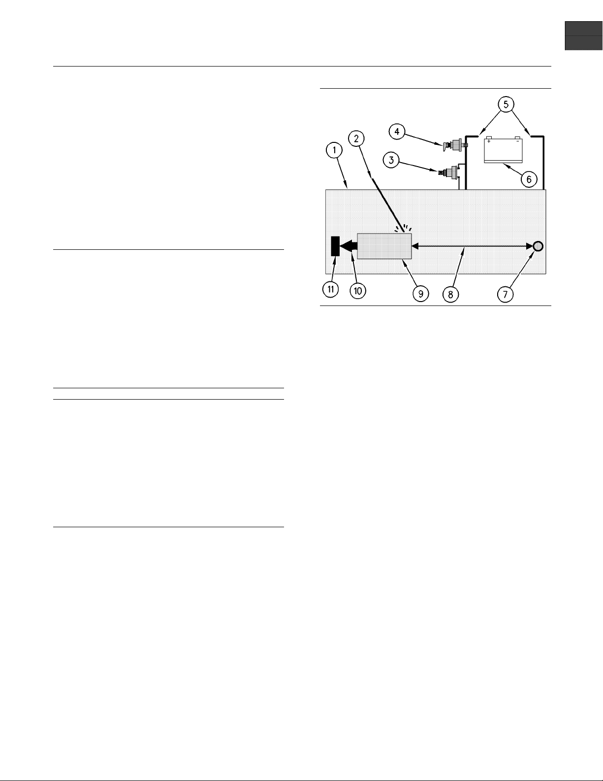
1. Stop the engine. Turn the switched power to the
OFF position.
2. Disconnect the negative battery cable from the
battery. If a battery disconnect switch is provided,
open the switch.
Illustration 15
Use the example above. T he current flow from the welder to
the ground clamp of the welder will not c ause damage to any
associated components.
(1) Engine
(2) Welding rod
(3) Keyswit ch in the OFF position
(4) Battery disconnect switch in the open position
(5) Disconnected battery cables
(6) Battery
(7) Electrical/Electronic component
(8) Maximum distance between the c ompo nent that is being
welded and any electrical/electronic component
(9) The component that is being welded
(10) Current path of the welder
(11) Ground clamp for the welder
4. Connect the welding ground cable directly to the
part that will be welded. Place the ground cable as
close as possible to the weld in order to reduce the
possibility of welding current damage to bearings,
hydraulic components, electrical components, and
ground straps.
Note: If electrical/electronic components are used
as a ground for the welder, or electrical/electronic
components are located between the welder ground
and the weld, current flow from the welder could
severely damage the component.
g00765012
3. Disconnect the J1/P1 connectors from the ECM.
Move the harness to a position that will not allow
the harness to accidentally move back and make
contact with any of the ECM pins.
5. Protect the wiring harness from welding debris
and spatter.
6. Use standard welding practices to weld the
materials.
Page 18
18 SEBU8119-02
Product Information Section
Model Views
Model Views
i02786384
Model View Illustrations
The following model views show typical features
of the engine.
engine may appear different from the illustrations.
Due to individual applications, your
Note: Only maj
or components are identified on the
following illustrations.
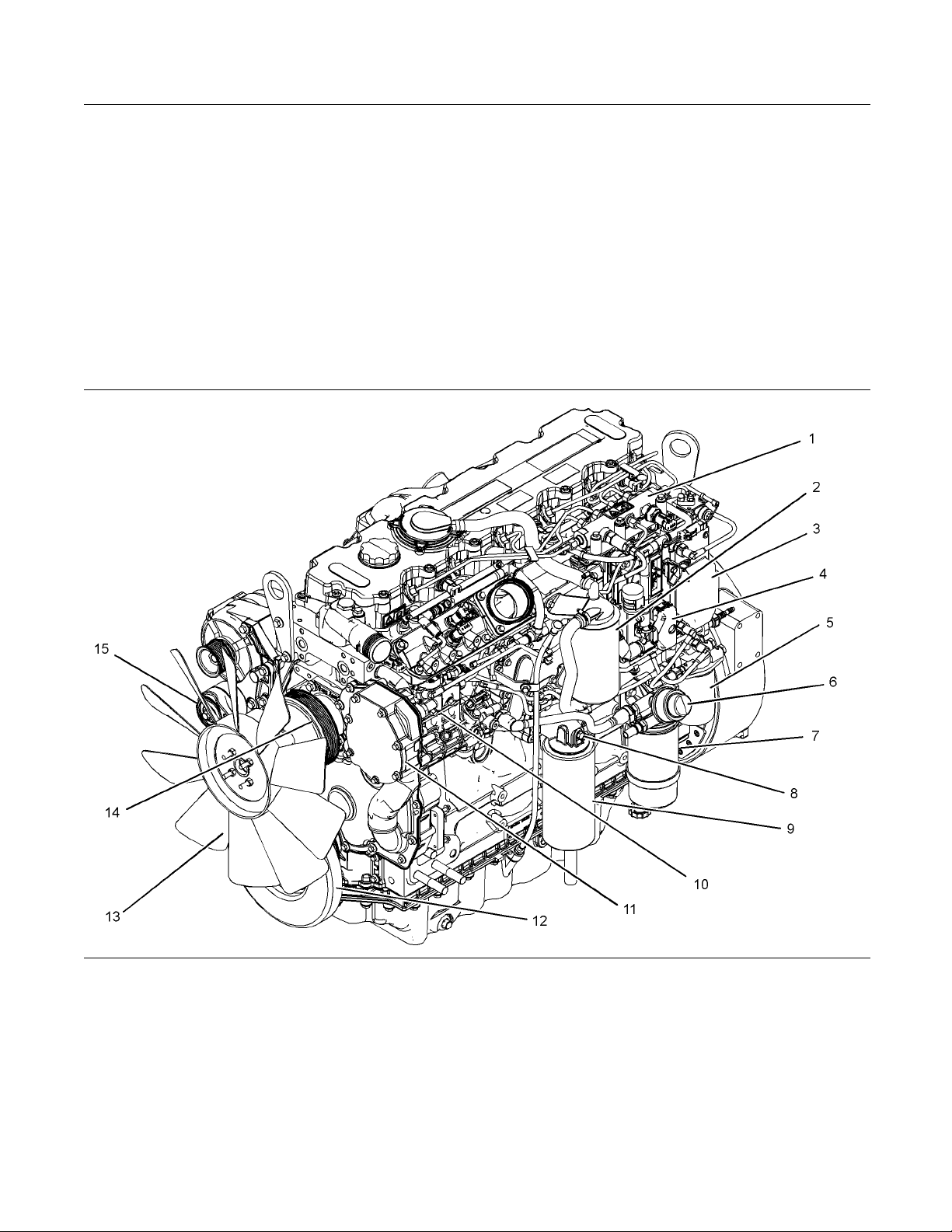
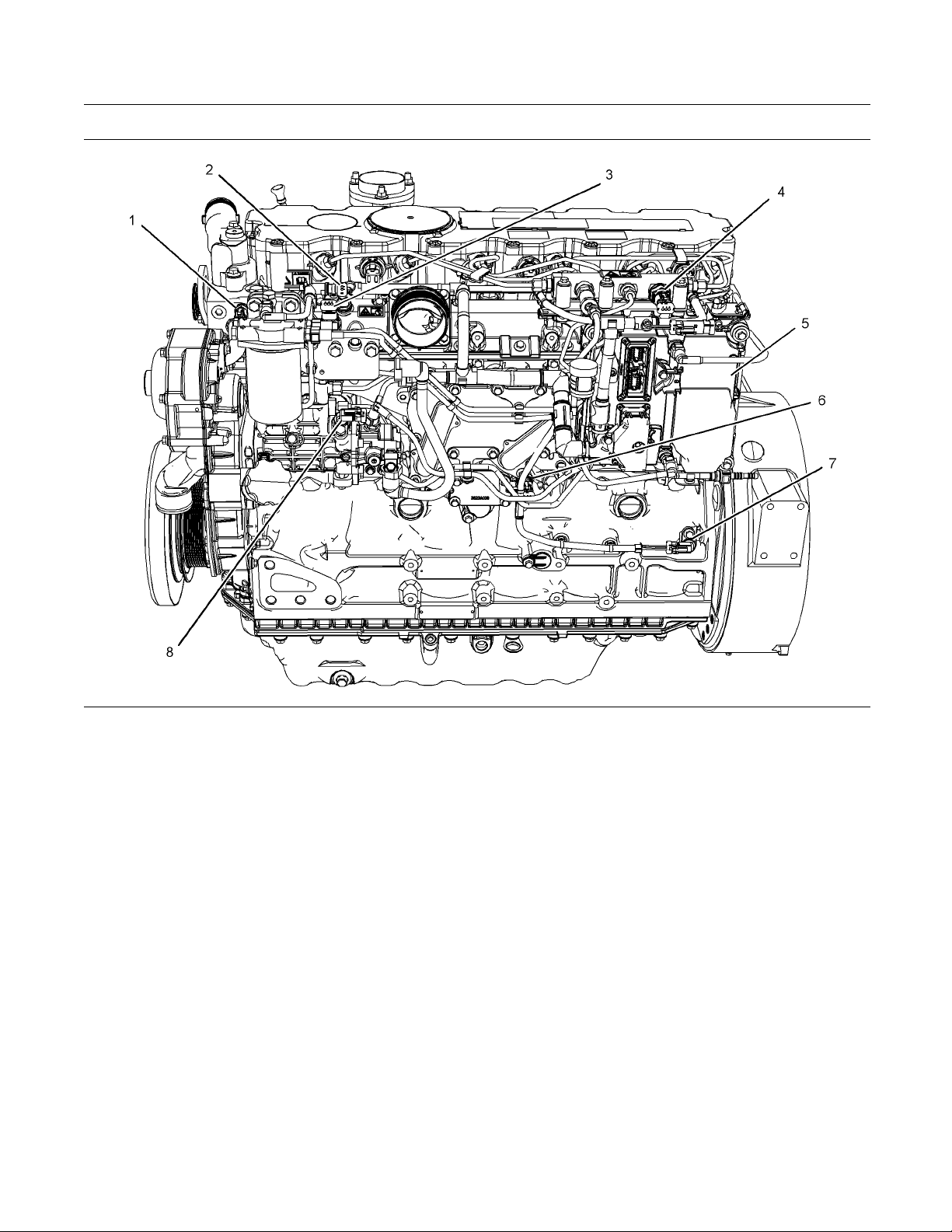
Illustration 1 6
Front left engine view
(1) Fuel manifold (Rail)
(2) Canister for the crankcase breather
(3) Electronic control module
(4) P2 connector
(5) Secondary fuel filter
(6) Hand primer
(7) Pr im ary fue l filter
(8) Oil sampling valve
(9) Oil filter
(10) Fuel pump
g01391892
(11) Water pump
(12) Damper
(13) Fan
(14) Fan pulley
(15) Belt tensioner
Page 19
SEBU8119-02 19
Product Information Section
Model Views
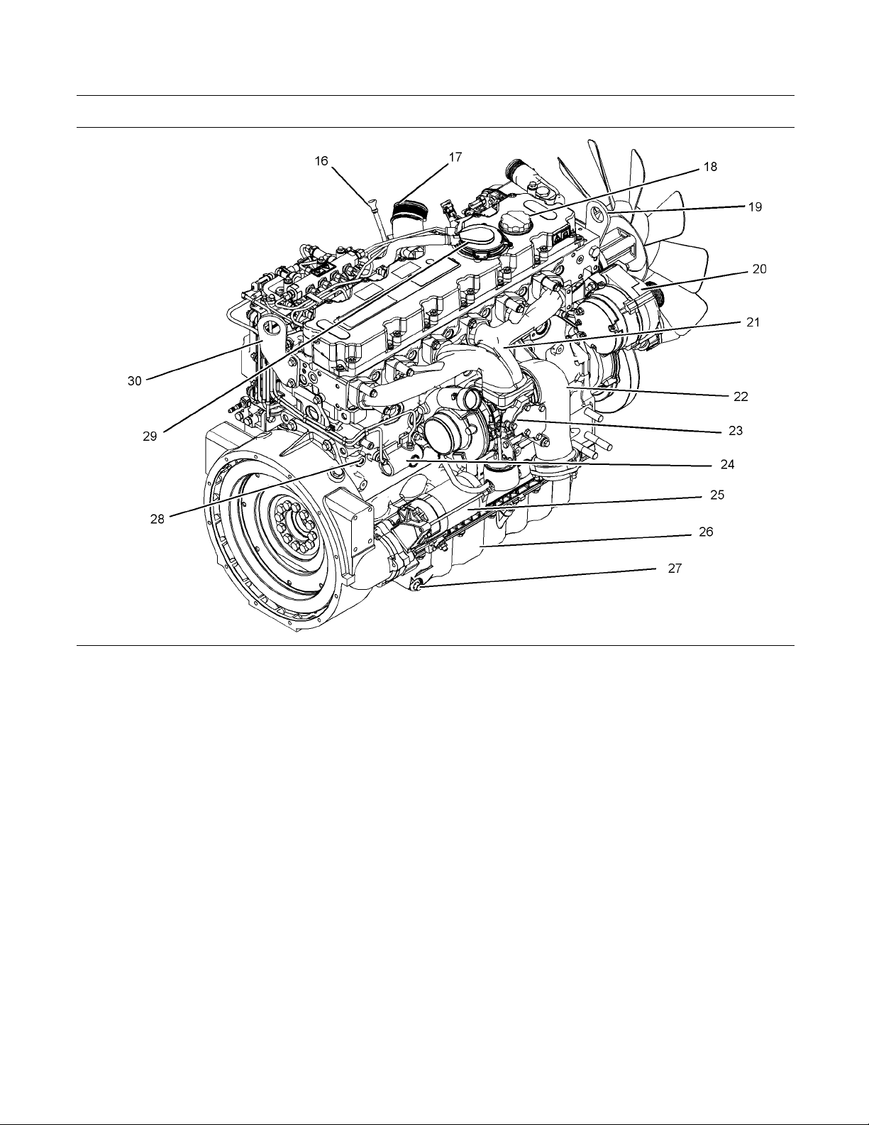
Illustration 1 7
Rear right engine view
(16) Oil gauge
(17) Air intake
(18) Oil filler
(19) Front lifting eye
(20) Alternator
(21) Exhaust manifold
(22) Exhaust elbow
(23) Turbocharger
(24) Wastegate solenoid
(25) Starting motor
i02715685
Engine Description
The 1106 Electronic Engine model PJ is designed
for the following applications: machine and industrial
mobile equipment. The engine is available in the
following type of aspiration:
Turbocharged aftercooled
•
Four stroke cycle
•
In-line 6 cylinder
•
g01391893
(26) Oil pan
(27) Drain plug (oil)
(28) Drain plug or coolant sampling valve
(29) Breather
(30) Rear lifting eye
Engine Specifications
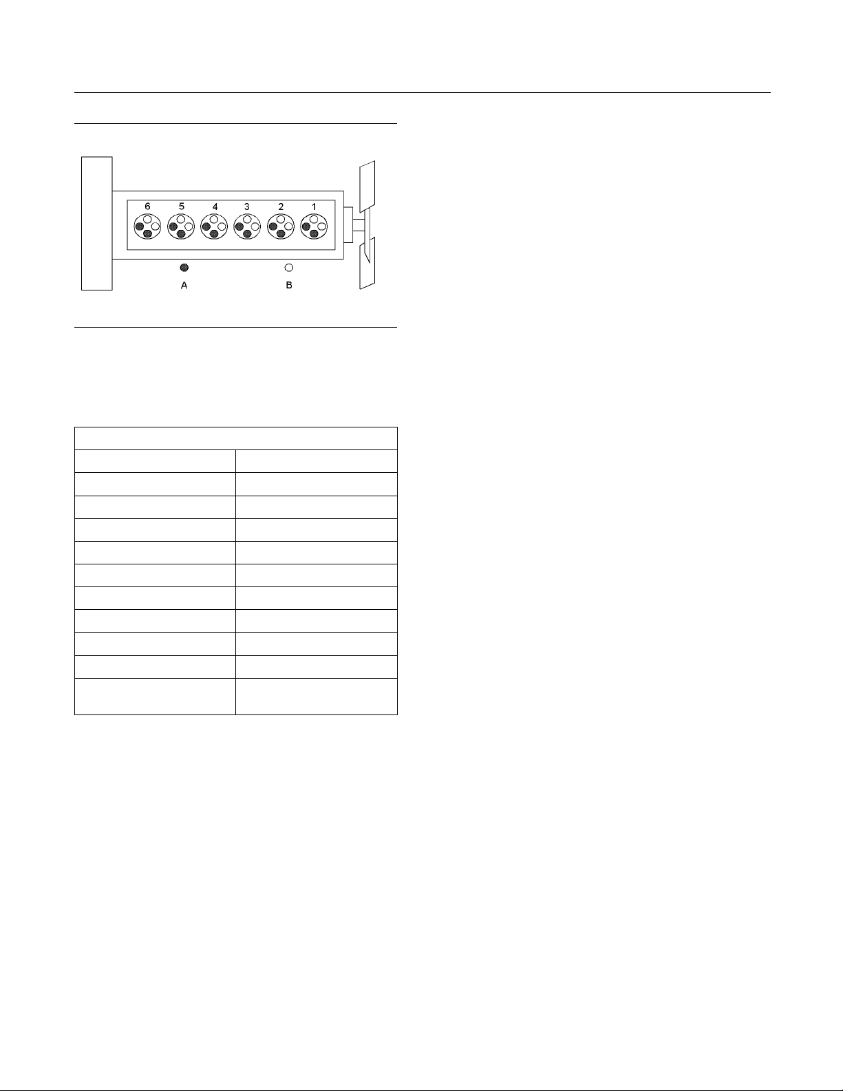
Note: The front end of the engine is opposite the
flywheel end of the engine. The left and the right
sides of the engine are determined from the flywheel
end. The number 1 cylinder is the front cylinder.
Page 20
20 SEBU8119-02
Product Information Section
Model Views
Illustration 18
1106 Electronic Engine model PJ
(A) Exhaust valves
(B) Inlet valves
Table 1
1106 Electronic Engine Model PJ Specifications
Operating Range (rpm)
Number of Cylinders 6 In-Line
Bore
Stroke 127 mm (5.0 inch)
Aspiration
Compression Ratio 16.2:1
Displacement 6.6 L (403 in3)
Firing Order 1-5-3-6-2-4
Rotation (fl
Valve Lash Setting (Inlet) 0.35 mm (0.013 inch)
Valve Lash Setting
(Exhaust)
(1)
The operating rpm is dependent on the engine rating, the
application and the configuration of the throttle.
ywheel end)
900 to 2800
105 mm (4.13 inch)
Turbocharged aftercooled
Counterclo
0.35 mm (0.013 inch)
g01127295
(1)
ckwise
Electronic Engine Features
Automatic air/
•
Torque rise shaping
•
Injection timing control
•
System diagno
•
fuel ratio control
stics
For more information on electronic engine features,
refer to the Op
eration and Maintenance Manual,
“Features and Controls” topic (Operation Section).
Engine Diagnostics
The engine has
that the engine systems are functioning correctly. The
operator will be alerted to the condition by a “Stop or
Warning” lam
horsepower and the vehicle speed may be limited.
Theelectronicservicetoolmaybeusedtodisplay
the diagnos
There are three types of diagnostic codes: active,
logged, and
Most of the diagnostic codes are logged and stored
in the ECM. F
the Operation and Maintenance Manual, “Engine
Diagnostics” topic (Operation Section).
The ECM provides an electronic governor that
controls the injector output in order to maintain the
desired en
Engine Coo
The cooling system consists of the following
component
Gear-driven centrifugal water pump
•
Water temperature regulator which regulates the
•
engine coolant temperature
built-in diagnostics in order to ensure
p. Under certain conditions, the engine
tic codes.
event.
or additional information, refer to
gine rpm.
ling and Lubrication
s:
The engine operating conditions are monitored.
The Electronic Control Module (ECM) controls the
response of the engine to these conditions and to
the demands of the operator. These conditions and
operator demands determine the precise control of
fuel injection by the ECM. The electronic engine
control system provides the following features:
Engine monitoring
•
Engine speed governing
•
Control of the injection pressure
•
Cold start strategy
•
Gear-driven rotor type oil pump
•
Oil cooler
•
The engine lubricating oil is supplied by a rotor type
oil pump.
The engine lubricating oil is cooled and the
engine lubricating oil is filtered. The bypass valve
can provide unrestricted flow of lubrication oil to
the engin
e if the oil filter element should become
plugged.
Page 21

SEBU8119-02 21
Product Information Section
Model Views
Engine efficien
engine performance depend on adherence to proper
operation and maintenance recommendations.
Engine perfor
the use of recommended fuels, lubrication oils, and
coolants. Refer to this Operation and Maintenance
Manual, “Mai
information on maintenance items.
cy, efficiency of emission controls, and
mance and efficiency also depend on
ntenance Interval Schedule” for more
Page 22
22 SEBU8119-02
Product Information Section
Product Identification Information
Product Identification
Information
Plate Locations and Film
Locations
i02650956
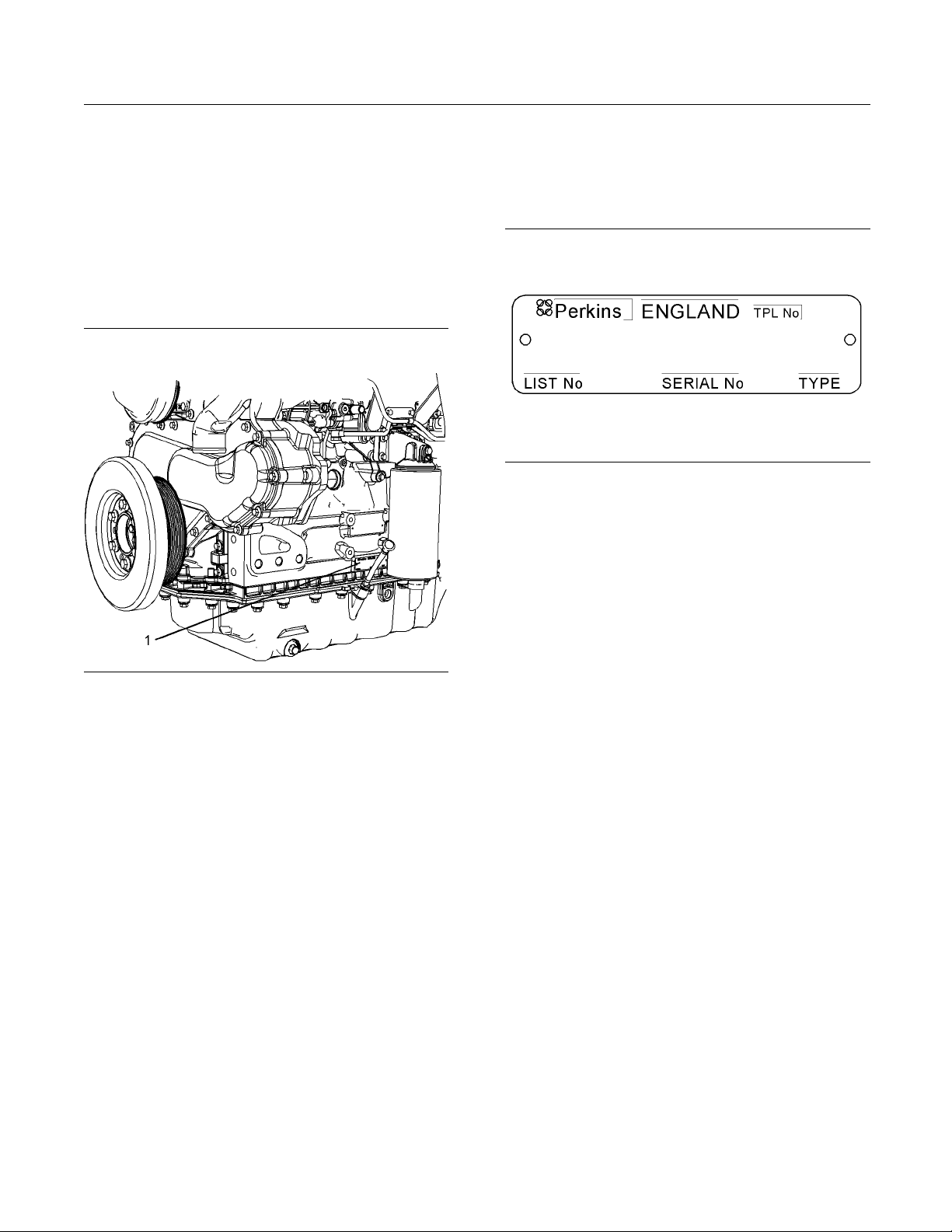
Serial Number Plate (1)
Theengineserialnumberplateislocatedonthe
left side of the cylinder block to the rear of the front
engine mounting.
on 20
Illustrati
Serial number plate
g01094203
i02164876
Reference Numbers
Illustration 19
Location of the serial number plate
g01331472
Perkins engines are identified by an engine serial
number.
An example of an engine number is PJ*****U000001J.
*****
____________________ The list number for the engine
__________________________________________ Type of engine
PJ
____________________________ Built in the United Kingdom
U
000001
J
___________________________ Engine Serial Number
_____________________________________ Year of Manufacture
Perkins dealers or Perkins distributors need all of
these numbers in order to determine the components
that were included with the engine. This permits
accurate identification of replacement part numbers.
The numbers for fuel setting information for electronic
engines are stored within the flash file. These
numbers can be read by using the electronic service
tool.
Informatio
n for the following items may be needed to
order parts. Locate the information for your engine.
Record the information in the appropriate space.
Makeacopyo
f this list for a record. Keep the
information for future reference.
Record for Reference
_______________________________________________
Engine Mod
Engine Serial number _____________________________________
Engine Low Idle rpm ______________________________________
Engine Ful
Primary Fuel Filter _________________________________________
Water Separator Element ________________________________
Secondary
Lubrication Oil Filter Element ___________________________
Auxiliary Oil Filter Element ________ _______________________
Tot al Lu br
Total Cooling System Capacity _________________________
el
l Load rpm
Fuel Filter Element
_____________________________________
__________________________
ication System Capacity
_____________________
Air Cleaner Element _______________________________________
Page 23
SEBU8119-02 23
Product Information Section
Product Identification Information
Fan Drive Belt _
_____________________________________________
Alternator Belt ______________________________________________
i02894856
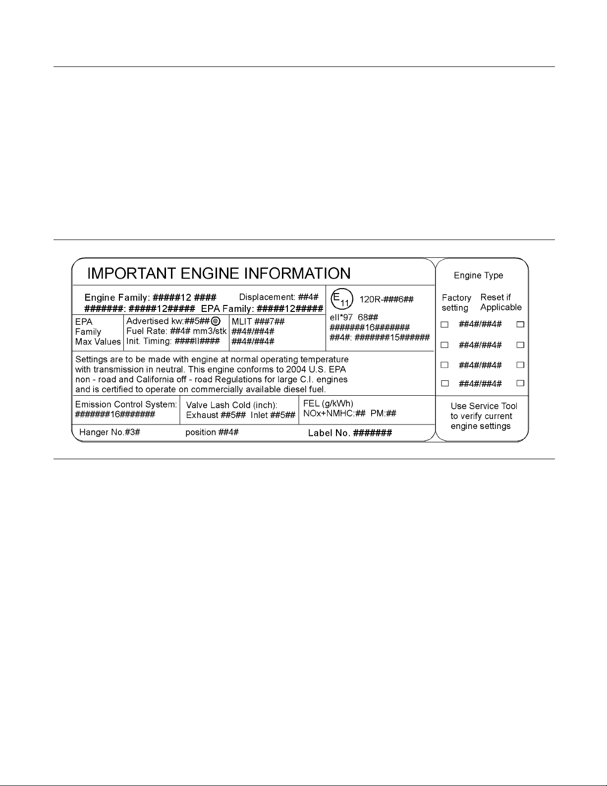
Emissions Certification Film
Label for compliant engines
Typical examp
les of emissions labels
Illustration 2 1
g01440937
Page 24
24 SEBU8119-02
Operation Section
Lifting and Storage
Operation Section
Lifting and Storage
Engine Lifting
i02164186
Some removals r
obtain correct balance and safety.
To r e m ov e t h e e
are on the engine.
Lifting eyes a
engine arrangements. Alterations to the lifting eyes
and/or the engine make the lifting eyes and the lifting
fixtures obso
that correct lifting devices are provided. Consult
your Perkins dealer or your Perkins distributor for
information
lifting.
equire lifting the fixtures in order to
ngine ONLY, use the lifting eyes that
re designed and installed for specific
lete. If alterations are made, ensure
regarding fixtures for correct engine
i02308881
Engine Storage
If the engine is not started for a month or longer the
lubricating oil will drain from the cylinder walls and
from the piston rings. Rust can form on the cylinder
walls. Rust on the cylinder walls will cause increased
engine wear and a reduction in engine service life.
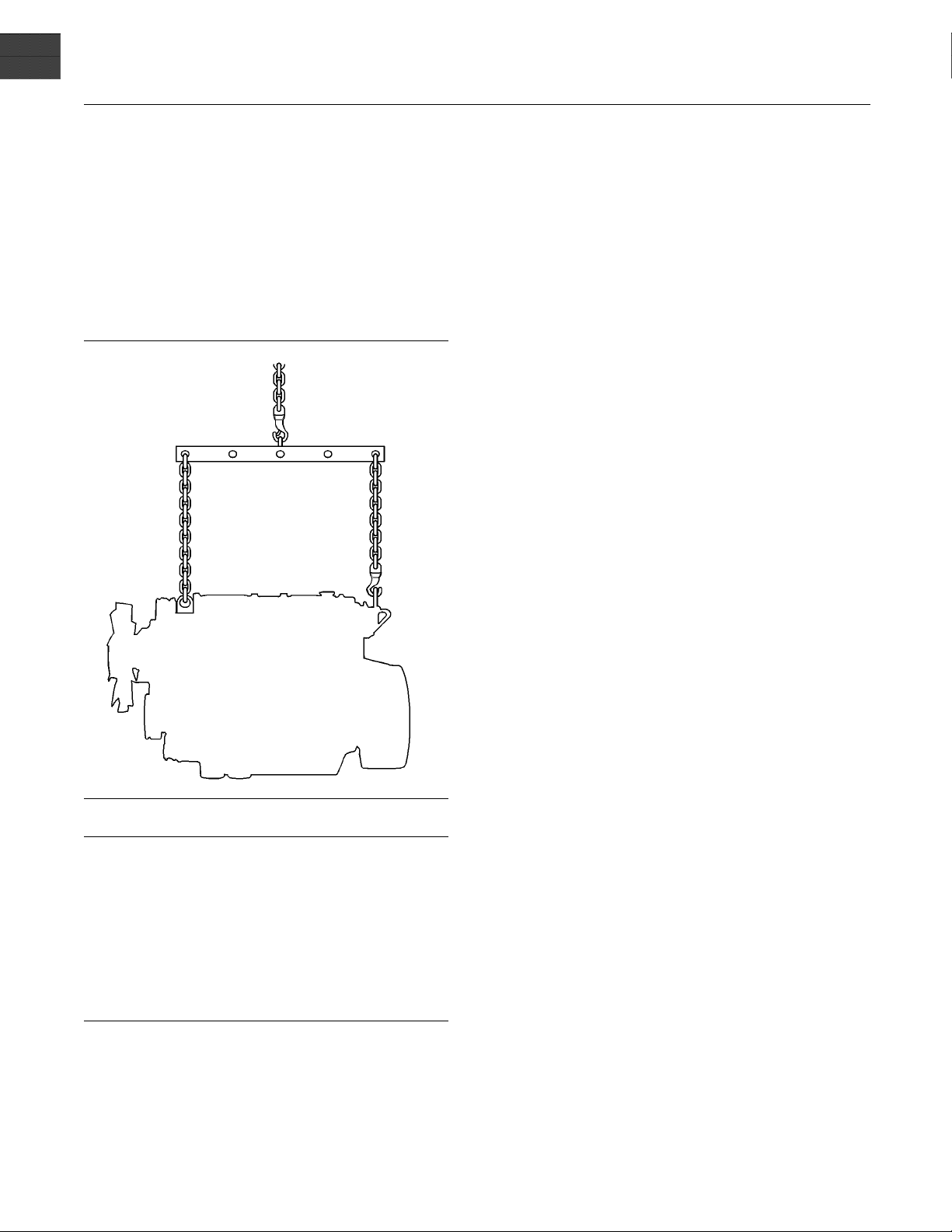
Illustration 22
NOTICE
Never bend the eyebolts and the brackets. Only load
the eyeb
ber that the capacity of an eyebolt is less as the angle
between the supporting members and the object becomes le
When it is necessary to remove a component at an
angle, o
the weight.
Use a ho
an adjustable lifting beam to lift the engine. All
supporting members (chains and cables) should be
parall
be perpendicular to the top of the object that is being
lifted.
olts and the brackets under tension. Remem-
ss than 90 degrees.
nly use a link bracket that is properly rated for
ist to remove heavy components. Use
el to each other. The chains and cables should
g01097527
Perkins are not responsible for damage which may
occur when an engine is in storage after a period in
service.
Your Perkins dealer or your Perkins distributor can
assist in preparing the engine for extended storage
periods.
If an engine is out of operation and if use of the
engine is not planned for more than one month, a
complete protection procedure is recommended.
To help prevent excessive engine wear and corrosion
to the engine, use the following guidelines:
1. Completely clean the outside of the engine.
2. Ensure that the vehicle is on level ground.
3. Drain the fuel system completely and refill
thesystemwithpreservativefuel.1772204
POWERPARTLay-Up1canbemixedwith
the normal fuel in order to change the fuel into
preservative fuel.
If preservative fuel is not available, the fuel system
can be filled with normal fuel. This fuel must be
discarded at the end of the storage period together
with the fuel filter elements.
Page 25
SEBU8119-02 25
Operation Section
Lifting and Storage
Personal injury can result from hot coolant. Any
contact with hot coolant or with steam can cause
severe burns. Allow cooling system components
to cool before the cooling system is drained.
4. Drain and refill the cooling system. Refer to this
Operation and Maintenance Manual, “Cooling
System coolant (Commercial Heavy Duty Change or Cooling System coolant (ELC) Change” for information on draining, flushing and
refilling the cooling system.
Contact with h igh pressure fuel may cause fluid
penetration and burn hazards. High pressure fuel spray may cause a fire hazard. Failure to follow these inspection, maintenance and service instructions may cause personal injury or death.
5. Operate the engine until the engine reaches
normal operating temperature. Stop the engine.
After the engine has stopped, you must wait for 60
seconds in order to allow the fuel pressure to be
purged from the high pressure fuel lines before any
service or repair is performed on the engine fuel
lines. If necessary, perform minor adjustments.
Repair any leaks from the low pressure fuel
system and from the cooling, lubrication or air
systems. Replace any high pressure fuel line that
has leaked. Refer to Disassembly and assembly
Manual, “Fuel Injection Lines - Install”.
6. Drain the lubricating oil from the oil pan.
Renew the canister(s) of the lubricating oil filter.
9. If equipped, re
element. Seal the end of the breather pipe.
10. Remove the val
1762811 POWERPART Lay-Up 2 around the
rocker shaft assembly.
11. Remove the glow plugs. Slowly rotate the
crankshaft. By checking the valves, position the
piston at BDC
Lay-Up 2 for two seconds into the cylinder bore.
This procedure must be carried out on each
cylinder.
12. Install the glow plugs. Install the valve mechanism
cover.
13. Remove the pipes that are installed between
the air filte
Spray 1762811 POWERPART Lay-Up 2 into
the turbocharger. The duration of the spray is
printed on
with waterproof tape.
14. Remove the
the turbocharger. Spray 1762811 POWERPART
Lay-Up 2 into the turbocharger. The duration of
the spray i
turbocharger with waterproof tape.
15. Seal the ve
with waterproof tape.
16. Remove the
belt into storage.
17. In order t
of the engine, spray the engine with 1734115
POWERPART Lay-Up 3. Do not spray the area
inside th
e alternator.
place the crankcase breather
ve mechanism cover. Spray
.Spray1762811 POWERPART
r assembly and the turbocharger.
the container. Seal the turbocharger
exhaust pipe from the output side of
s printed on the container. Seal the
nt of the fuel tank or the fuel filler cap
alternator drive belt and put the drive
o prevent corrosion to the outside
Fill the oil pan to the Full Mark on the engine oil
level gauge with new, clean lubricating oil. Add
1762811 POWERPARTLay-Up2totheoilin
order to protect the engine against corrosion. If
1762811 POWERPART Lay-Up 2 is not available,
use a preservative of the correct specification
instead of the lubricating oil. If a preservative is
used, this must be drained completely at the end
of the storage period and the oil pan must be
refilled to the correct level with normal lubricating
oil.
7. Operate the engine in order to circulate engine oil.
8. Disconnect the battery. Ensure that the battery is
in a fully charged condition. Protect the terminals
against corrosion. 1734115 POWERPART
Lay-Up 3 can be used on the terminals. Put the
battery into safe storage.
Page 26
26 SEBU8119-02
Operation Section
Gauges and Indicators
Gauges and Ind icators
i02717240
Gauges and Indicators
Your engine m
the gauges that are described. For more information
about the gauge package, see the OEM information.
Gauges provide indications of engine performance.
Ensure that the gauges are in good working order.
Determine th
the gauges over a period of time.
Noticeable c
potential gauge or engine problems. Problems may
also be indicated by gauge readings that change
even if the r
Determine and correct the cause of any significant
change in the readings. Consult your Perkins dealer
or your Per
Some engine applications are equipped with Indicator
Lamps. Ind
aid. There are two lamps. One lamp has an orange
lens and the other lamp has a red lens.
These indicator lamps can be used in two ways:
The indica
•
current operational status of the engine. The
indicator lamps can also indicate that the engine
has a faul
via the ignition switch.
The indic
•
diagnostic codes. This system is activated by
pressing the Flash Code button.
Refer to the Troubleshooting Guide, “Indicator
Lamps” for further information.
If no oil pressure is indicated, STOP the engine. If
maximum coolant temperature is exceeded, STOP
the engine. Engine damage can result.
SAE10W40is350to450kPa(50to65psi)atrated
rpm.
A lower oil pressure is normal at low idle. If the load
is stable and the gauge reading changes, perform
the following procedure:
ay not have the same gauges or all of
e normal operating range by observing
hanges in gauge readings indicate
eadings are within specifications.
kins distributor for assistance.
icator lamps can be used as a diagnostic
torlampscanbeusedtoidentifythe
t. This system is automatically operated
ator lamps can be used to identify active
NOTICE
Engine Oil Pressure – The oil pressure
should be greatest after a cold engine is
started. The typical engine oil pressure with
1. Remove the load
2. Stop the engine.
3. Check and maintain the oil level.
Jacket Water C
Typical temperature range is 83° to 95°C
(181.4° to 171°F). The maximum allowable
temperature a
system at 48 kPa (7 psi) is 103 °C (217.4 °F). Higher
temperatures may occur under certain conditions.
The water tem
to load. The temperature reading should never
exceed 7 °C (44.6 °F) below the boiling point for the
pressurized
A 100 kPa (14.5 psi) radiator cap may be installed on
the cooling system. The temperature of this cooling
system must n
If the engine is operating above the normal range
and steam be
procedure:
1. Reduce the l
2. Determine if the engine must be shut down
immediatel
reducing the load.
3. Inspect the
load, the engine is running at high idle. The engine is
running at
lever is at the full throttle position with maximum
rated load.
To help prevent engine damage, never exceed the
high idle rpm. Overspeeding can result in serious
damage to the engine. Operation at speeds exceeding high idle rpm should be kept to a minimum.
indicator should be to the “+” side of “0” (zero).
is in the “on” position.
system that is being used.
Tachometer – This gauge indicates engine
speed (rpm
ismovedtothefullthrottlepositionwithout
thefullloadrpmwhenthethrottlecontrol
Ammeter – This gauge indicates the
amount of charge or discharge in the
battery charging circuit. Operation of the
Fuel Level – This gauge indicates the fuel
level in the fuel tank. The fuel level gauge
operates when the “START/STOP” switch
.
oolant Temperature –
t sea level with the pressurized cooling
perature reading may vary according
ot exceed 112 °C (233.6 °F).
comes apparent, perform the following
oad and the engine rpm.
y or if the engine can be cooled by
cooling system for leaks.
). When the throttle control lever
NOTICE
Page 27

SEBU8119-02 27
Operation Section
Gauges and Indicators
Service Hour Meter – The gauge indicates
total operating hours of the engine.
Page 28
28 SEBU8119-02
Operation Section
Features and Controls
Features and Controls
i02651062
Monitoring System
If the Shutdown mode has been selected and the
warning indi
take as little as 20 seconds from the time the warning indic ator is activated. Depending on the application, s
avoid personal injury. The engine can be restarted
following shutdown for emergency maneuvers, if
necessary.
The Engine Monitoring System is not a guarantee
against catastrophic failures. Programmed delays
and derate schedules are designed to minimize false
alarms and provide time for the operator to stop the
engine.
The following parameters are monitored:
Coolant temperature
•
Intake air temperature
•
Engine intake manifold pressure
•
Engine Oil pressure
•
Pressure in the fuel rail
•
cator activates, engine shutdown may
pecial precautions should be taken to
NOTICE
“Warning”
The “Warning” lamp and the warning signal (orange
lamp) turn “ON
continuously in order to alert the operator that one or
more of the engine parameters is not within normal
operating ra
” and the warning signal is activated
nge.
“Warning/Derate”
The “Diagnostic” lamp turns “ON” and the warning
signal (red lamp) is activated. After the warning, the
engine power
begin to flash when the derating occurs.
Theenginewi
preset operational limits. The engine derate is
achieved by restricting the amount of fuel that is
available f
reduction of fuel is dependent on the severity of the
fault that has caused the engine derate, typically up
to a limit o
predetermined reduction in engine power.
“Warning/
The “Diagnostic” lamp turns “ON” and the warning
signal (re
the engine power will be derated. The engine will
continue at the rpm of the set derate until a shutdown
of the engi
after a shutdown for use in an emergency.
A shutdow
as 20 seconds. The engine can be restarted after
a shutdown for use in an emergency. However,
the cause
Theenginemayshutdownagaininaslittleas20
seconds.
will be derated. The warning lamp will
ll be derated if the engine exceeds
or each injection. The amount of this
f 50%. This reduction in fuel results in a
Derate/Shutdown”
d lamp) is activated. After the warning,
ne occurs. The engine can be restarted
n of the engine may occur in as little
of the initial shutdown may still exist.
Engine speed/timing
•
Programmable O ptions and
Systems Operation
If the Warning/Derate/Shutdown mode has been
selected and the warning indicator activates,
bring the engine to a stop whenever possible. Depending on the application, special precautions
should be taken to avoid personal injury.
The engine can be programmed to the following
modes:
If there is a signal for low oil pressure or for coolant
temperature, there will be a two second delay in
order to
For each of the programmed modes, refer to
Trouble
information on Indicator Lamps.
For m ore
your Perkins dealer or your Perkins distributor.
verify the condition.
shooting , “Indicator Lamps” for more
information or assistance for repairs, consult
Page 29

SEBU8119-02 29
Operation Section
Features and Controls
i02296746
Monitoring System
Table 2
Warning
Lamp
ON ON
OFF OFF
ON OFF
ON FLASHING
FLASHING OFF
FLASHING FLASHING
ON ON
Shutdown
Lamp
Lamp Status Description of lamp status Engine Status
Lamp check When the engine start switch is turned to the
“ON” position both lamps w ill illuminate for 2
seconds only.
No faults There are no active diagnostic faults.
Active
diagnostic
fault
Active
diagnostic
fault
Warning One or more of the engine protection values
Derate and
warning
Engine
shutdown
An active diagnostic fault has been detected.
A serious active diagnostic fault has been
detected and an engine derate has been
invoked.
has been exceeded.
One or more of the engine protection values
has been exceeded.
One or more of the engine protection values has
been exceeded or a serious active diagnostic
fault has b
een detected.
The engine has not been
started.
Theengineisrunning
normally.
Theengineisrunning
normally.
Theengineisrunning
but the engine has been
derated.
Theengineisrunning
normally.
Theengineisrunning
but the engine has been
derated.
The engine is shutdown or
shutdown is imminent.
i02788240
Sensors and Electrical
Components
Sensor Locations
tion 23 shows the typical locations of the
Illustra
sensors on the engine. Specific engines may appear
different from the illustration due to differences in
applicat
Module (ECM) is illustrated.
ions. The location of the Electronic Control
Page 30
30 SEBU8119-02
Operation Section
Features and Controls
Illustration 2 3
(1) Coolant tempe rature sensor
(2) Intake manifold air tem perature sensor
(3) Intake manifold pressure sensor
(4) Fuel pressure sensor
(5) Electronic control mod ule (ECM)
(6) Oil pressure sensor
g01392818
(7) Primary pos ition sensor
(8) Secondary position sensor
Page 31

SEBU8119-02 31
Operation Section
Features and Controls
Illustration 2 4
(1) Coola
(2) Intak
nt temperature sensor
e manifold air temperature sensor
e manifold pressure sensor
(3) Intak
(4) Fuel p
ressure sensor
ronic control module (ECM)
(5) Elect
g01330220
Illustration 2 5
(6) Engine oil pressure sensor (7) Primary speed/timing sensor (8) Secondary speed/timing sensor
g01330325
Page 32

32 SEBU8119-02
Operation Section
Features and Controls
Illustration 2
andtheECMinpositionontheengine.
4 and illustration 25 shows the sensors
Failure of Sensors
All Sensors
A failure of any of the sensors may be caused by one
of the followi
Sensor output is open.
•
Sensor output is shorted to “- battery” or “+ battery”.
•
Measured read
•
specification.
ng malfunctions:
ing of the sensor is out of the
Programmable Monitoring System
(PMS)
The Programmable Monitoring System determines
the level of a
Module (ECM) (5) in response to a condition that can
damage the engine. These conditions are identified
by the ECM fr
the following sensors.
ction that is taken by the Engine Control
om the signals that are produced from
Failure of the C
oolant Temperature
Sensor
The ECM (5) wil
temperature sensor. The diagnostic lamp will warn the
operator about the status of the coolant temperature
sensor. A fai
will not cause a shutdown of the engine or any
horsepower change. In order to check the correct
operation of
“Engine Temperature Sensor Circuit - Test”.
l detect a failure of the coolant
lure of the coolant temperature sensor
the sensor, refer to Troubleshooting,
Intake Manifold Air Temperature
Sensor 2
The intake manifold air temperature sensor measures
the intake a
ECM (5). The intake manifold air temperature sensor
is also used by the ECM to determine initiation of the
Cold Start
In order to check the correct operation of the sensor,
refer to Tr
Circuit - Test”.
ir temperature. A signal is sent to the
Strategy.
oubleshooting, “EngineTemperature Sensor
Intake Manifold Pressure Sensor 3
Coolant Tem
•
Intake manifold Air Temperature Sensor
•
Intake manifold Pressure Sensor
•
Fuel Pressu
•
Engine Oil Pressure Sensor
•
Primary Speed/Timing Sensor
•
Secondary S
•
Coolant Tem
The coolant temperature sensor monitors engine
coolant tem
indicate a high coolant temperature through a relay
or a lamp. The coolant temperature sensor is used
by the ECM t
Condition.
perature Sensor
re Sensor
peed/Timing Sensor
perature Sensor 1
perature. The output of the ECM (5) can
o determine initiation of the Cold Start
The intake
pressure in the manifold. A signal is sent to the ECM
(5).
manifold pressure sensor measures
Fuel Pressure Sensor 4
The fuel pressure sensor measures the fuel pressure
in the fuel manifold. A signal is sent to the ECM (5).
Electronic Control Module 5
The ECM is the control computer of the engine. The
ECM provides power to the electronics. The ECM
monitors
engine. The ECM acts as a governor in order to
control the speed and the power of the engine.
The ECM adjusts injection timing and fuel pressure
for the best engine performance, the best fuel
economy
Engine O
The engine oil pressure sensor is an absolute
pressur
pressure in the main oil gallery. The engine oil
pressure sensor detects engine oil pressure for
diagno
sends a signal to the ECM (5).
data that is input from the sensors of the
and the best control of exhaust emissions.
il Pressure Sensor 6
e sensor that measures the engine oil
stic purposes. The engine oil pressure sensor
Page 33

SEBU8119-02 33
Operation Section
Features and Controls
Low Oil Pressur
The setpoint for the low pressure warning is
dependent upo
active and logged only if the engine has been running
for more than 8 seconds.
e Warning
n the engine speed. The fault will be
Very Low Oil Pressure Warning
The very low oi
upon the engine speed. If the DERATE mode of the
engine monitoring system is selected, the ECM (5)
will derate t
will be limited.
Failure of th
The ECM (5) will detect failure of the engine oil
pressure sen
about the status of the engine oil pressure sensor.
The engine oil pressure related strategies will be
disabled in
pressure sensor. A failure of the engine oil pressure
sensor will not cause a shutdown of the engine or
any horsep
operation of the sensor, refer to Troubleshooting, “5
Volt Sensor Supply Circuit - Test”.
l pressure setpoint is dependent
he engine power. The engine horsepower
e Engine Oil Pressure Sensor
sor. The diagnostic lamp warns the user
the event of a failure of the engine oil
ower change. In order to check the correct
Primary Speed/Timing Sensor 7
If the ECM (5) does not receive a signal from the
primary speed/timing sensor , the “DIAGNOSTIC”
lamp will i
logged in the ECM memory.
If the ECM
speed/timing sensor (7), the ECM will read the signal
from the secondary speed/timing sensor (8). The
ECM conti
is a signal from both sensors.
ndicate a diagnostic fault code which will be
does not receive a signal from the primary
nually checks in order to determine if there
Secondary Speed/Timing Sensor 8
The signal from the secondary speed/timing sensor
is used by the ECM (5) on engine start-up in order
to check the stroke of the pistons. The secondary
speed/timing sensor may be used by the ECM
in order to operate the engine if the primary
speed/timing sensor is faulty.
In order to check the correct operation of the sensor,
refer to Troubleshooting, “Engine speed/Timing
sensor-Test”.
i02858345
Engine Shutoffs and E ngine
Alarms
Shutoffs
The shutoffs are electrically operated or mechanically
operated. The electrically operated shutoffs are
controlled by the ECM.
Shutoffs are set at critical levels for the following
items:
Operating temperature
•
Operating pressure
•
Operating level
•
Operating rpm
•
The particular shutoff may need to be reset before
theenginewillstart.
Intermi
engine control.
Failure
ttent failure of the sensors will cause erratic
of the Primary Speed/Timing
Sensor
Correct
sensor is essential. Software in the ECM protects
against reverse running of the engine. If the primary
speed/
protection against reverse running. In some
applications, it is possible for the transmission to
run the
engine immediately. Turn the keyswitch to the “OFF”
position.
In order to check the correct operation of the sensor,
refer to Troubleshooting, “Engine speed/Timing
senso
operation of the primary speed/timing
timing sensor fails there is no automatic
engine in reverse. In this event, Stop the
r-Test”.
NOTICE
Always determine the cause of the engine shutdown.
Make necessary repairs before attempting to restart
the engine.
Be familiar with the following items:
Types and locations of shutoff
•
Conditions which cause each shutoff to function
•
The resetting procedure that is required to restart
•
the engine
Alarms
The alarms are electrically operated. The operation
of the alarms are controlled by the ECM.
Page 34

34 SEBU8119-02
Operation Section
Features and Controls
The alarm is ope
When the sensor or the switch is activated a signal
is sent to the ECM. An event code is created by
the ECM. The EC
illuminate the lamp.
Your engine m
sensors or switches:
Coolant leve
indicates when the coolant level is low.
Coolant temp
sensor indicates high jacket water coolant
temperature.
Intake manifold air temperature – The intake
manifold air temperature sensor indicates high intake
air tempera
Intake manifold pressure – The intake manifold
pressure se
engine manifold.
Fuelrailpr
checks for high pressure or low pressure in the fuel
rail.
Engine oil pressure – The engine oil pressure
sensor indicates when oil pressure drops below rated
system pre
rated by a sensor or by a switch.
Mwillsendasignalinorderto
ay be equipped with the following
l–The low coolant level switch
erature – The coolant temperature
ture.
nsor checks the rated pressure in the
essure – The fuel rail pressure sensor
ssure, at a set engine speed.
If corrective m
reasonable time, engine damage could result. The
alarm will continue until the condition is corrected.
The alarm may n
easures are not taken within a
eed to be reset.
Testing
TurningthekeyswitchtotheONpositionwillcheck
the indicato
indicator lights will be illuminated for two seconds
after the keyswitch is operated. Replace suspect
bulbs immedi
Refer to Troubleshooting for more information.
r lights on the control panel. All the
ately.
i02237393
Overspeed
An overspeed condition is detected by the Electronic
Control Module (ECM). The event code will be
logged if the engine speed exceeds 3000 rpm. The
“DIAGNOSTIC” lamp will indicate a diagnostic active
code. The diagnostic active code will remain active
until the engine speed drops to 2800 rpm.
Engine overspeed – The primary speed/timing
sensor che
activated at 3000 RPM.
Air filter
filter when the engine is operating.
User defin
the engine remotely.
Water in f
in t he primary fuel filter when the engine is operating.
Note: The
temperature switch must be submerged in coolant
in order to operate.
Engines may be equipped with alarms in order
to alert the operator when undesirable operating
conditi
When an alarm is activated, corrective measures must
be taken before the situation becomes an emergency
in order
cks the engine speed. The alarm is
restriction – The switch checks the air
ed switch – This switch can shut down
uel switch – This switch checks for water
sensing element of the coolant
ons occur.
NOTICE
to avoid possible engine damage.
Page 35

SEBU8119-02 35
Operation Section
Engine Diagnostics
Engine Diagnostics
i02651093
Self-Diagnostics
Perkins electronic engines have the capability to
perform a self-diagnostics test. When the system
detects an active problem, a diagnostic lamp
is activated. Diagnostic codes will be stored in
permanent memory in the Electronic Control Module
(ECM). The diagnostic codes can be retrieved
by using the electronic service tool. Refer to
Troubleshooting , “Electronic Service Tools” for
further information.
Some installations have electronic displays that
provide direct readouts of the engine diagnostic
codes. Refer to the manual that is provided
by the OEM for more information on retrieving
engine diagnostic codes. Alternatively refer to
Troubleshooting , “Indicator Lamps” for further
information.
Active codes represent problems that currently exist.
These problems should be investigated first.
Logged codes represent the following items:
Intermittent problems
•
Recorded events
•
Performance history
•
The problems may have been repaired since the
logging of the code. These codes do not indicate that
a repair is needed. The codes are guides or signals
when a situation exists. Codes may be helpful to
troubleshoot problems.
When the problems have been corrected, the
corresponding logged fault codes should be cleared.
i02651107
Diagnostic Lamp
A diagnostic lamp is used to indicate the existence of
an activ
Lamps” for more information. A fault diagnostic
code will remain active until the problem is repaired.
The dia
electronic service tool. Refer to Troubleshooting ,
“Electronic Service Tools” for more information.
e fault. Refer to Troubleshooting , “Indicator
gnostic code may be retrieved by using the
i02857828
Diagnostic Flash Code
Retrieval
“Diagnostic” Lamp
Use the “DIAGNOSTIC” lamp or an electronic service
tool to determine the diagnostic flash code.
Usethefollowingproceduretoretrievetheflash
codes if the engine is equipped with a “DIAGNOSTIC”
lamp:
1. Move the keyswitch from the on/off two times
within three
A flashing YELLOW lamp indicates a 3 digit code for
the engine. T
system diagnostic message. Count the first sequence
of flashes in order to determine the first digit of the
flash code. A
sequence of flashes will identify the second digit of
the flash code. After the second pause, the third
sequence of
Any additional flash codes will follow after a pause.
These code
Flash Code 551 indicates that No Detected Faults
have occurred since the ignition keyswitch has been
turned to t
For further information, assistance for repairs, or
troubles
consult your Perkins distributor.
Table3 li
brief description of the flash codes.
Note: Ta b
performance with “ACTIVE” flash codes.
Some code
may also indicate that a mechanical system needs
attention. Troubleshooting is not required for code
“551”. Co
codes will limit the operation or the performance of
the engine.
Table3 indicates the potential effect on the engine
performance with active flash codes. Table 3 also
forms a l
descriptions.
hooting, refer to the Service Manual or
sts the flash codes and the table also gives a
seconds.
he sequence of flashes represents the
fter a two second pause, the second
flashes will identify the flash code.
s will be displayed in the same manner.
he ON position.
le3 indicates the potential effect on engine
s record events. Also, some codes
de 001 will not display a flash code. Some
ist of Electronic diagnostic codes and
Page 36

36 SEBU8119-02
Operation Section
Engine Diagnostics
Table 3
Flash Codes for 1106D Industrial Engine
Diagnostic
Effect On Engine Performance
(2)
Flash Code
Description Engine
Misfire
Low
Power
Reduced
Engine
Speed
111 No. 1 Injector Fault X X X
112 No. 2 Injector Fault X X X
113 No. 3 Injector Fault X X X
114 No. 4 Injector Fault X X X
115 No. 5 Injector Fault X X X
116 No. 6 Injector Fault X X X
133
Intake Manif
old Air
XX
Temperature sensor
(5)
fault
141 Primary Engi
ne
XX
Speed/Timing Sensor
(6)
Fault
142 Secondary Engine
Speed/Timing Sensor
Fault
143 Engine Timing
XX
Calibration Fault
144
Engine Operation Mode
XX
Selector Switch Fault
151 High Air Filter
XX
Restriction
154 Throttle Position sensor
XX
Fault
155 Secondary Throttle
XX
Position sensor Fault
157
Engine Oil Pressure
XX
Sensor Fault
159 Fuel Rail
Pressure
XX
Sensor Fault
162 Fuel Rail Pressure
enoid Fault
168
Val v e So l
Engine Coolant
XX X
Temperature Sensor
Faul
169 Low Engine Coolant X X
177 Turbo Wastegate
X
Actuator Fault
185 High Exhaust
XX
Temperature
197
Intake Manifold Boost
XX
Pressure Fault
(1)
Engine
Shutdown
Suggested Operator
Action
(3)
Service
Schedule
a Service.
X
X
(continued)
(4)
Page 37

SEBU8119-02 37
Operation Section
Engine Diagnostics
(Table 3, contd)
199
415 Incorrect Engine
426
429 Ignition Key Switch
511
514 SAE J1939 Data Link
516
517
527
(1)
If warning lamps ar e installed refer to this table. For installations that have electronic displays, refer to the O EM for information.
(2)
An “X” indicates that the effect on engine performance may occur if the code is active.
(3)
The operato
(4)
Schedule Service: The problem should be investigated when the operator has access to a qualified service program.
(5)
These Flash Codes may affect the system under specific environmental conditions such as engine start-up at cold temperature and
cold weather operation at high altitudes.
(6)
If the primar
immediately
“Engine spe
(6)
The engine will not start.
Glow Plug Start Relay
Fault
Software
Machine Security
System Module Fault
Fault
ECM Power Supply
Voltage Fault
Fault
5 Volt Sensor DC
Power Supply Fault
8 Volt Sensor DC
Power Supply Fault
Customer/S
Parmeter Fault
r should go to the nearest location that has a qualified service program.
y engine speed/timing sensor fails there is no automatic protection against reverse running. In this event, Stop the engine
. Turn the keyswitch to the “OFF” position. In order to check the correct operation of the sensor, refer to Troubleshooting,
ed/Timing sensor - Test”.
ystem
(6)
XX X X
XX
XX
XX X
XX X
XX
X
X
X
i01902949
Fault Logging
The system p
When the Electronic Control Module (ECM)
generates an active diagnostic code, the code will
be logged in
that have been logged by the ECM can be identified
by the electronic service tool. The active codes that
have been l
has been rectified or the fault is no longer active.
The following logged faults can not be cleared from
the memory
password: Overspeed, low engine oil pressure, and
high engine coolant temperature.
rovides the capability of Fault Logging.
the memory of the ECM. The codes
ogged will be cleared when the fault
of the ECM without using a factory
i02651197
Engine Operation with Active
Diagnostic
If a diagnostic lamp illuminates during normal engine
operation, the system has identified a situation that is
not within t
tool to check the active diagnostic codes.
The active d
The cause of the problem should be corrected as
soon as possible. If the cause of the active diagnostic
code is rep
diagnostic code, the diagnostic lamp will turn off.
Operation
engine can be limited as a result of the active
diagnostic code that is generated. Acceleration rates
may be sig
be automatically reduced. Refer to Troubleshooting
, “Troubleshooting with a Diagnostic Code” for more
informat
diagnostic code and the possible effect on engine
performance.
he specification. Use the electronic service
iagnostic code should be investigated.
aired and there is only one active
of the engine and performance of the
nificantly slower and power outputs may
ion on the relationship between each active
Codes
Page 38

38 SEBU8119-02
Operation Section
Engine Diagnostics
i01902995
Engine O peration with
Intermittent
If a diagnostic lamp illuminates during normal engine
operation and the diagnostic lamp shuts off, an
intermittent
occurred, the fault will be logged into the memory of
the Electronic Control Module (ECM).
In most cases, it is not necessary to stop the engine
because of an intermittent code. However, the
operator sho
and the operator should reference the appropriate
information in order to identify the nature of the event.
The operato
have caused the lamp to light.
fault may have occurred. If a fault has
uld retrieve the logged fault codes
r should log any observation that could
Diagnostic Co des
Low power
•
Limits of the engine speed
•
Excessive smoke, etc
•
This inform
the situation. The information can also be used for
future reference. For more information on diagnostic
codes, ref
engine.
ation can be useful to help troubleshoot
er to the Troubleshooting Guide for this
Page 39

SEBU8119-02 39
Operation Section
Engine Starting
Engine Starting
i02322201
Before Starting Engine
Before the en
daily maintenance and any other periodic
maintenance that is due. Refer to the Operation
and Maintena
Schedule” for more information.
Open the fuel
•
All valves in the fuel return line must be open before
andduringen
pressure. High fuel pressure may cause filter housing
failure or other damage.
If the engine has not been started for several weeks,
fuel may have drained from the fuel system. Air
may have ent
filters have been changed, some air pockets will be
trapped in the engine. In these instances, prime the
fuel syste
Manual, “Fuel System - Prime” for more information
on priming the fuel system.
gine is started, perform the required
nce Manual, “Maintenance Interval
supply valve (if equipped).
NOTICE
gine operation to help prevent high fuel
ered the filter housing. Also, when fuel
m. Refer to the Operation and Maintenance
i02322203
Starting the Eng ine
Note: Do not adj
start-up. The electronic control module (ECM) will
control the engine speed during start-up.
Starting the Engine
1. Disengage any equipment that is driven by the
engine.
2. Turn the keyswitch to the RUN position. Leave the
keyswitchintheRUNpositionuntilthewarning
light for the
3. When the warning light for the glow plugs is
extinguishe
position in order to engage the electric starting
motor and crank the engine.
Note: The operating period of the warning light for
the glow plugs will change due to the temperature
of the engin
Do not engage the starting motor when flywheel is
turning. Do
ust the engine speed control during
glow plugs is extinguished.
dturnthekeyswitchtotheSTART
e.
NOTICE
not start the engine under load.
Engine ex
which may be harmful to your health. Always start
and operate the engine in a well ventilated area
and, if in
outside.
Do not sta
•
if there is a “DO NOT OPERATE” warning tag or
similar warning tag attached to the start switch or
to the con
Reset all o f the shutoffs or alarm components (if
•
equippe
Ensure that any equipment that is driven by the
•
engine h
Minimize electrical loads or remove any electrical
loads.
haust contains products of combustion
an enclosed area, vent the exhaust to the
rt the engine or move any of the controls
trols.
d).
as been disengaged from the engine.
If the engine fails to start within 30 seconds, release
the starter
allow the starting motor to cool before attempting to
start the engine again.
4. Allow the keyswitch to return to the RUN position
after the engine starts.
5. Repeat step 2 through step 4 if the engine fails
to start.
switch or button and wait two minutes to
i02325155
Cold Weather Starting
Do not use aerosol types of starting aids such as
ether. Such use could result in an explosion and
personal injury.
Startability will be improved at temperatures below
−18 °C (0 °F) from the use of a jacket water heater
or extra battery capacity.
Page 40

40 SEBU8119-02
Operation Section
Engine Starting
When Group 2 die
provide a means of minimizing starting problems
and fuel problems in cold weather: Engine oil pan
heaters, jack
line insulation.
Use the proce
starting.
Note: Do not a
start-up. The electronic control module (ECM) will
control the engine speed during start-up.
1. Disengage any driven equipment.
2. Turn the keys
keyswitch in the RUN position until the warning
light for the glow plugs is extinguished.
Do not engage the starting motor when flywheel is
turning. Do not start the engine under load.
If the engine fails to start within 30 seconds, release
the starter switch or button and wait two minutes to
allow the st
start the engine again.
sel fuel is used, the following items
et water heaters, fuel heaters, and fuel
dure that follows for cold weather
djust the engine speed control during
witch to the RUN position. Leave the
NOTICE
arting motor to cool before attempting to
i02322204
Starting with Jump Start
Cables
Improper jump start cable connections can cause
an explosion resulting in personal injury.
Prevent sparks near the batteries. Sparks could
cause vapors to explode. Do not allow jump start
cable e nds to contact each other or the engine.
Note: If it is possible, first diagnose the reason for
the starting failure. Refer to Troubleshooting, “Engine
Will Not Crank and Engine Cranks But Will Not Start”
for further information. Make any necessary repairs. If
the engine will not start only due to the condition of the
battery, either charge the battery, or start the engine
by using another battery with jump start cables.
The condition of the battery can be rechecked
after the engine has been switched OFF.
3. When the war
extinguished turn the keyswitch to the START
position in order to engage the electric starting
motor and c
Note: The operating period of the warning light for
the glow pl
of the engine.
4. Allow the k
after the engine starts.
5. Repeat ste
to start.
Note: The
speed up the warm up process.
6. Allow the
allow the engine to idle until the water temperature
indicator begins to rise. When idling after the
engine ha
engine rpm from 1000 to 1200 rpm. This will
warm up the engine more quickly. Maintaining
an eleva
will be easier with the installation of a hand
throttle. Allow the white smoke to disperse before
proceed
ning light for the glow plugs is
rank the engine.
ugs will change due to the temperature
eyswitch to return to the RUN position
p 2 through step 4 if the engine fails
engine should not be “raced” in order to
engine to idle for three to five minutes, or
s started in cold weather, increase the
ted low idle speed for extended periods
ing with normal operation.
NOTICE
Using a battery source with the same voltage as the
electric starting motor. Use ONLY equal voltage for
jump starti
the electrical system.
Do not reve
be damaged. Attach ground cable last and remove
first.
Turn all electrical accessories OFF before attaching
the jump start cables.
Ensure that the main power switch is in the OFF position before attaching the jump start cables to the engine bein
1. Turn the start switch on the stalled engine to the
OFF posit
2. Connect one positive end of the jump start cable
to the pos
battery. Connect the other positive end of the jump
start cable to the positive cable terminal of the
electri
ng. The use of higher voltage will damage
rse the battery cables. The alternator can
gstarted.
ion. Turn off all the engine’s accessories.
itive cable terminal of the discharged
cal source.
7. Operate the engine at low load until all systems
reach op
during the warm-up period.
erating temperature. Check the gauges
Page 41

SEBU8119-02 41
Operation Section
Engine Starting
3. Connect one neg
to the negative cable terminal of the electrical
source. Connect the other negative end of the
jump start cab
chassis ground. This procedure helps to prevent
potential sparks from igniting the combustible
gases that ar
4. Start the engine.
5. Immediately after the engine is started, disconnect
the jump start cables in reverse order.
After jump starting, the alternator may not be able to
fully recharge batteries that are severely discharged.
The batterie
proper voltage with a battery charger after the engine
is stopped. Many batteries which are considered
unusable ar
and Maintenance Manual, “Battery - Replace” and
Testing and Adjusting Manual, “Battery - Test”.
s must be replaced or charged to the
e still rechargeable. Refer to Operation
ative end of the jump start cable
le to the engine block or to the
e produced by some batteries.
i02330138
After Starting Engine
Note: In ambient temperatures from 0 to 60°C
(32 to 140°F), the warm-up time is approximately
three minutes. In temperatures below 0°C (32°F),
additional warm-up time may be required.
When the engine idles during warm-up, observe the
following conditions:
Do not check the high pressure fuel lines with the
engine or the starting motor in operation. If you
inspect the engine in operation, always use the
proper inspection procedure in order to avoid a
fluid penetration hazard. Refer to Operation and
Maintenance Manual, “General hazard Information”.
Check for any fluid or for any air leaks at idle rpm
•
and at one-half full rpm (no load on the engine)
before operating the engine under load. This is not
possible in some applications.
Allow the engine to idle for three to five minutes, or
•
allow the engine to idle until the water temperature
indicator begins to rise. Check all gauges during
the warm-up period.
Note: Gauge readings should be observed and
the data should be recorded frequently while the
engine is operating. Comparing the data over time
will help to determine normal readings for each
gauge.Comparingdataovertimewillalsohelp
detect abnormal operating developments. Significant
changes in the readings should be investigated.
Page 42

42 SEBU8119-02
Operation Section
Engine Operation
Engine Operation
i02330143
Engine Operation
Correct oper
in obtaining the maximum life and economy of
the engine. If the directions in the Operation and
Maintenance
minimized and engine service life can be maximized.
The engine ca
engine reaches operating temperature. The engine
will reach normal operating temperature if the engine
is operated
light load. This procedure is more effective than idling
the engine at no load. The engine should reach
operating
Gauge readings should be observed and the data
should be r
is operating. Comparing the data over time will
help to determine normal readings for each gauge.
Comparing
abnormal operating developments. Significant
changes in the readings should be investigated.
ation and maintenance are key factors
Manual are followed, costs can be
n be operated at the rated rpm after the
at low idle speed and operated with a
temperature in a few minutes.
ecorded frequently while the engine
data over time will also help detect
i02330149
Fuel Conservation Practices
The efficiency o
economy. Perkins design and technology in
manufacturing provides maximum fuel efficiency in
all applicati
in order to attain optimum performance for the life
of the engine.
Avoid spilling fuel.
•
Fuel expands
may overflow from the fuel tank. Inspect fuel lines for
leaks. Repair the fuel lines, as needed.
Be aware of the properties of the different fuels.
•
Use only the recommended fuels.
Avoid unnecessary idling.
•
Shut off the
time.
Observe the
•
Keep the air cleaner elements clean.
Maintain th
•
f the engine can affect the fuel
ons. Follow the recommended procedures
when the fuel is warmed up. The fuel
engine rather than idle for long periods of
air cleaner service indicator frequently.
e electrical systems.
One damaged battery cell will overwork the alternator.
This will co
Ensure that the drive belts are correctly adjusted.
•
The drive be
Ensure that all of the connections of the hoses are
•
tight. The
Ensure that the driven equipment is in good
•
working or
Cold engines consume excess fuel. Utilize heat
•
from the ja
system, when possible. Keep cooling system
components clean and keep cooling system
component
engine without water temperature regulators.
All of these items will help maintain operating
temperat
nsume excess power and excess fuel.
lts should be in good condition.
connections should not leak.
der.
cket water system and the exhaust
s in good repair. Never operate the
ures.
Page 43

SEBU8119-02 43
Operation Section
Engine Stopping
Engine Stopping
i02334873
Stopping the Engine
NOTICE
Stopping the engine immediately after it has been
working under load, can result in overheating and accelerated wear of the engine components.
Avoid accelerating the engine prior to shutting it down.
Avoiding hot engine shutdowns will maximize turbocharger shaft and bearing life.
Note: Individual applications will have different
control systems. Ensure that the shutoff procedures
are understood. Use the following general guidelines
in order to stop the engine.
1. Remove the load from the engine. Reduce the
engine speed (rpm) to low idle. Allow the engine
to idle for five minutes in order to cool the engine.
2. Stop the engine after the cool down period
according to the shutoff system on the engine and
turn the ignition key switch to the OFF position.
If necessary, refer to the instructions that are
provided by the OEM.
i01903586
Emergency
Stopping
i02330274
After Stopping Engine
Note: Before yo
the engine for at least 10 minutes in order to allow
the engine oil to return to the oil pan.
Contact with h
penetration and burn hazards. High pressure fuel spray may cause a fire hazard. Failure to follow these ins
structions may cause personal injury or death.
After the eng
•
60 seconds in order to allow the fuel pressure to
be purged from the high pressure fuel lines before
any service
fuel lines. If necessary, perform minor adjustments.
Repair any leaks from the low pressure fuel
system and f
systems. Replace any high pressure fuel line that
has leaked. Refer to Disassembly and assembly
Manual, “F
Check the crankcase oil level. Maintain the oil level
•
between th
the engine oil level gauge.
If the engi
•
note the reading. Perform the maintenance that
is in the Operation and Maintenance Manual,
“Mainten
u check the engine oil, do not operate
igh pressure fuel may cause fluid
pection, maintenance and service in-
ine has stopped, you must wait for
or repair is performed on the engine
rom the cooling, lubrication or air
uel Injection Lines - Install”.
e “MIN” mark and the “MAX” mark on
ne is equipped with a service hour meter,
ance Interval Schedule”.
NOTICE
Emergency shutoff controls are for EMERGENCY use
ONLY. DO NOT use emergency shutoff devices or
controls for normal stopping procedure.
The OEM may have equipped the application with
an emergency stop button. For more information
about the emergency stop button, refer to the OEM
information.
Ensure that any components for the external system
that support the engine operation are secured after
the engine is stopped.
Fill the fuel tank in order to help prevent
•
accumula
the fuel tank.
Only use antifreeze/coolant mixtures recommended in
the Coola
and Maintenance Manual. Failure to do so can cause
engine damage.
Pressurized System: Hot coolant can cause serious burns. To open the cooling system filler cap,
stop the engine and wait until the cooling system
components are cool. Loosen the cooling system
pressure cap slowly in order to relieve the pressure.
Allow the engine to cool. Check the coolant level.
•
tion of moisture in the fuel. Do not overfill
NOTICE
nt Specifications that are in the Operation
Page 44

44 SEBU8119-02
Operation Section
Engine Stopping
Check the coola
•
and the correct corrosion protection. Add the
correct coolant/water mixture, if necessary.
Perform all required periodic maintenance on all
•
driven equipment. This maintenance is outlined in
the instruct
nt for correct antifreeze protection
ions from the OEM.
Page 45

SEBU8119-02 45
Operation Section
Cold Weather Operation
Cold Weather Operation
i02717265
Cold Weather O perat ion
Perkins Diesel Engines can operate effectively in
cold weather. During cold weather, the starting and
the operation of the diesel engine is dependent on
the following items:
The type of fuel that is used
•
The viscosity of the engine oil
•
The operation of the glow plugs
•
Optional Cold starting aid
•
Battery condition
•
This section will cover the following information:
Potential problems that are caused by cold weather
•
operation
Suggest steps which can be taken in order to
•
minimize starting problems and operating problems
when the ambient air temperature is between
0° to−40 °C (32° to 40 °F).
Install the cor
•
before the beginning of cold weather.
Check all rubb
•
weekly.
Check all elec
•
fraying or damaged insulation.
Keep all batte
•
Fill the fuel tank at the end of each shift.
•
Check the air cleaners and the air intake daily.
•
Check the air intake more often when you operate
in snow.
Ensure that the glow plugs are in working order.
•
Refer to Test
-Test”.
Personal injury or property damage can result
from alcohol or starting fluids.
Alcohol or starting fluids are highly flammable and
toxic and if improperly stored could result in injury
or property
rect specification of engine lubricant
er parts (hoses, fan drive belts, etc)
trical wiring and connections for any
ries fully charged and warm.
ing and Adjusting Manual, “Glow Plug
damage.
The operation and maintenance of an engine in
freezing temperatures is complex . This is because
of the following conditions:
Weather conditions
•
Engine applications
•
Recommendations from your Perkins dealer or
your Perkins distributor are based on past proven
practices. The information that is contained in
this section provides guidelines for cold weather
operation.
Hints for Cold Weather Operation
If the engine will start, operate the engine until a
•
minimum operating temperature of 81 °C (177.8 °F)
is achieved. Achieving operating temperature will
help prevent the intake valves and exhaust valves
from sticking.
The cooling system and the lubrication system
•
for the engine do not lose heat immediately upon
shutdown. This means that an engine can be shut
downforaperiodoftimeandtheenginecanstill
have the ability to start readily.
Do not use aerosol types of starting aids such as
ether. Such use could result in an explosion and
personal injury.
Forjumpstartingwithcablesincoldweather,
•
refer to the Operation and Maintenance Manual,
“Starting with Jump Start Cables.” for instructions.
Viscosity of the Engine Lubrication
Oil
Correct engine oil viscosity is essential. Oil viscosity
affects the amount of torque that is needed to
crank the engine. Refer to this Operation and
Maintenance Manual, “Fluid Recommendations” for
the recommended viscosity of oil.
Recommendations for the Coolant
Provide cooling system protection for the lowest
expected outside temperature. Refer to this Operation
and Maintenance Manual, “Fluid Recommendations”
for the recommended coolant mixture.
Page 46

46 SEBU8119-02
Operation Section
Cold Weather Operation
In cold weather
correct glycol concentration in order to ensure
adequate freeze protection.
, check the coolant often for the
Engine Block Heaters
Engine block h
engine jacket water that surrounds the combustion
chambers. This provides the following functions:
Startability is improved.
•
Warm up time i
•
An electric block heater can be activated once
the engine is
is typically a 1250/1500 W unit. Consult your
Perkins dealer or your Perkins distributor for more
information
Idling the E
When idling after the engine is started in cold
weather, in
rpm. This will warm up the engine more quickly.
Maintaining an elevated low idle speed for extended
periods wil
throttle. The engine should not be “raced” in order to
speed up the warm up process.
While the engine is idling, the application of a light
load (parasitic load) will assist in achieving the
minimum op
operating temperature is 82 °C (179.6 °F).
eaters (if equipped) heat the
s reduced.
stopped. An effective block heater
.
ngine
crease the engine rpm from 1000 to 1200
l be easier with the installation of a hand
erating temperature. The minimum
Recommendations for Coolant
Warm Up
Warm up an engine that has cooled below normal
operatin
be performed before the engine is returned to full
operation. During operation in very cold temperature
conditio
result from engine operation for short intervals. This
can happen if the engine is started and the engine is
stopped
to warm up completely.
When the
temperatures, fuel and oil are not completely burned
in the combustion chamber. This fuel and oil causes
soft ca
Generally, the deposits do not cause problems and
the deposits are burned off during operation at
normal
When the engine is started and the engine is stopped
many ti
up completely, the carbon deposits become thicker.
This can cause the following problems:
g temperatures due to inactivity. This should
ns, damage to engine valve mechanisms can
many times without being operated in order
engine is operated below normal operating
rbon deposits to form on the valve stems.
engine operating temperatures.
mes without being operated in order to warm
Free operation
•
Valves become stuck.
•
Pushrods may become bent.
•
Other damage t
•
result.
For this reaso
the engine must be operated until the coolant
temperature is 71 °C (160 °F) minimum. Carbon
deposits on t
and the free operation of the valves and the valve
components will be maintained.
In addition, the engine must be thoroughly warmed in
order to keep other engine parts in better condition
and the servi
extended. Lubrication will be improved. There will be
less acid and less sludge in the oil. This will provide
longer serv
rings, and other parts. However, limit unnecessary
idle time to ten minutes in order to reduce wear and
unnecessa
ry fuel consumption.
of the valves is prevented.
o valve train components can
n, when the engine is started,
he valve stems will be kept at a minimum
celifeoftheenginewillbegenerally
ice life for the engine bearings, the piston
The Water Temperature Regulator and
Insulated
The engine is equipped with a water temperature
regulator
correct operating temperature jacket water circulates
through the engine cylinder block and into the
engine cy
cylinder block via an internal passage that bypasses
the valve of the coolant temperature regulator. This
ensures t
cold operating conditions. The water temperature
regulator begins to open when the engine jacket
water ha
temperature. As the jacket water coolant temperature
rises above the minimum operating temperature the
water te
more coolant through the radiator to dissipate excess
heat.
The progressive opening of the water temperature
regulator operates the progressive closing of the
bypass
head. This ensures maximum coolant flow to
the radiator in order to achieve maximum heat
pation.
dissi
Note: Perkins discourages the use of all air flow
iction devices such as radiator shutters.
restr
Restriction of the air flow can result in the following:
high exhaust temperatures, power loss, excessive
fan us
Heater Lines
. When the engine coolant is below the
linder head. The coolant then returns to the
hat coolant fl ows around the engine under
s reached the correct minimum operating
mperature regulator opens further allowing
passage between the cylinder block and
age, and reduction in fuel economy.
Page 47

SEBU8119-02 47
Operation Section
Cold Weather Operation
A cab heater is b
feed from the engine and the return lines from the
cab should be insulated in order to reduce heat loss
to the outside
eneficial in very cold weather. The
air.
Insulating the Air Inlet and Engine
Compartment
When temperatures below −18 °C (−0°F)willbe
frequently e
is located in the engine compartment may be
specified. An air cleaner that is located in the engine
compartment
into the air cleaner. Also, heat that is rejected by the
engine helps to warm the intake air.
Additional heat can be retained around the engine by
insulating the engine compartment.
ncountered, an air cleaner inlet that
may also minimize the entry of snow
i02685960
Fuel and t he Effect from Cold
Weather
Note: Only use grades of fuel that are recommended
by Perkins. Refer to this Operation and Maintenance
Manual, “Flui
The following components provide a means of
minimizing p
Glow plugs (if equipped)
•
Engine coolant heaters, which may be an OEM
•
option
Fuel heaters, which may be an OEM option
•
Fuel line ins
•
The cloud point is a temperature that allows wax
crystals to f
the fuel filters to plug.
d Recommendations”.
roblems in cold weather:
ulation, which may be an OEM option
orm in the fuel. These crystals can cause
The pour poin
will thicken. The diesel fuel becomes more resistant
to flow through fuel lines, fuel filters,and fuel pumps.
Be aware of these facts when diesel fuel is
purchased. Consider the average ambient air
temperatur
that are fueled in one climate may not operate well if
the engines are moved to another climate. Problems
can result
Before troubleshooting for low power or for poor
performan
Low temperature fuels may be available for engine
operation
fuels limit the formation of wax in the fuel at low
temperatures.
For more information on cold weather operation, refer
to the Operation and Maintenance Manual, “Cold
Weather O
Cold Weather”.
t is the temperature when diesel fuel
e for the engine’s application. Engines
due to changes in temperature.
ce in the winter, check the fuel for waxing.
at temperatures below 0 °C (32 °F). These
peration and Fuel Related Components in
Page 48

48 SEBU8119-02
Operation Section
Cold Weather Operation
i02323237
Fuel Related Components in
Cold Weather
Fuel Tanks
Condensation can form in partially filled fuel tanks.
Top off the fuel tanks after you operate the engine.
Fuel tanks should contain some provision for draining
water and sediment from the bottom of the tanks.
Some fuel tanks use supply pipes that allow water
and sediment to settle below the end of the fuel
supply pipe.
Some fuel tanks use supply lines that take fuel
directly fro
equipped with this system, regular maintenance of
the fuel system filter is important.
m the bottom of the tank. If the engine is
Drain the water and sediment from any fuel storage
tank at the following intervals: weekly, service
intervals,
prevent water and/or sediment from being pumped
from the fuel storage tank and into the engine fuel
tank.
Fuel Filte
A primary fuel filter is installed between the fuel
tank and th
the fuel filter, always prime the fuel system in order
to remove air bubbles from the fuel system. Refer
to the Ope
Maintenance Section for more information on priming
the fuel system.
The location of a primary fuel filter is important in cold
weather operation. The primary fuel filter and the fuel
supply li
are affected by cold fuel.
and refueling of the fuel tank. This will help
rs
e engine fuel inlet. After you change
ration and Maintenance Manual in the
ne are the most common components that
Fuel Heaters
Note: Th
heaters. If this is the case, the temperature of the fuel
must not exceed 73 °C (163 °F) at the fuel transfer
pump.
e OEM may equip the application with fuel
For more information about fuel heaters (if equipped),
refer to
the OEM information.
Page 49

SEBU8119-02 49
Maintenance Section
Refill Capacities
Maintenance Section
Refill Capacities
i02237872
Refill Capacities
Lubrication System
The refill capacities for the engine crankcase
reflect the approximate capacity of the crankcase
or sump plus standard oil filters. Auxiliary oil filter
systems will require additional oil. Refer to the OEM
specifications for the capacity of the auxiliary oil filter.
Refer to the Operation and Maintenance Manual,
“Maintenance Section” for more information on
Lubricant Specifications.
Table 4
Engine
Refill Capacities
Compartment or System
Crankcase Oil Sump
(1)
These values are t he approximate capacities for the crankcase
oil sump (aluminum) which includes the standard factory
installed oil filters. Engines with auxiliary oil filters will require
additional oil. Refer to the OEM specifications for the capacity
of the auxiliary oil filter.
(1)
Cooling System
Minimum Maximum
13.5 L
(2.9696
Imp gal)
16.5 L
(3.6295
Imp gal)
i02788820
Fluid Recommendations
(Fuel Specifica
Glossary
•
ISO Internati
•
ASTM American Society for Testing and Materials
•
HFRR High Frequency Reciprocating Rig for
•
Lubricity testing of diesel fuels
FAME Fatty Acid Methyl Esters
•
CFR Co-ordina
•
LSD Low Sulfur Diesel
•
ULSD Ultra Low Sulfur Diesel
•
RME Rape Methy
•
SME Soy Methyl Ester
•
EPA Environmental Protection Agency of the
•
United States
General Information
Every attempt is made to provide accurate, up to date
information.
Perkins Engines Company Limited is not responsible
forerrorsoromissions.
onal Standards Organization
ting Fuel Research
By use of this document you agree that
tion)
lEster
NOTICE
Refer to the OEM specifications for the External
System capacity. This capacity information will
be needed in order to determine the amount of
coolant/antifreeze that is required for the Total
Cooling System.
Table 5
Engine
Refill Capacities
Compartment or System
Engine Only
External System Per OEM
(1)
The External System includes a radiator or an expansion
tank w ith the following com ponents: heat exchanger and
piping. Refer to the OEM specifications. Enter the value for the
capacity of the External System in this row.
(1)
Liters
9 L (1.9797
Imp gal)
NOTICE
These recommendations are subject to change without notice. Contact your local Perkins distributor for
the most up to date recommendations.
Diesel Fuel R
Satisfactory engine performance is dependent on
theuseofago
quality fuel will give the following results: long engine
life and acceptable exhaust emissions levels. The
fuel must me
stated in table 6.
The footnotes are a key part of the Perkins Specification for Dis
footnotes.
et the minimum requirements that are
tillate Diesel Fuel Table. Read ALL of the
equirements
od quality fuel. The use of a good
NOTICE
Page 50

50 SEBU8119-02
Maintenance Section
Refill Capacities
Table 6
Perkins Specification for Distillate Diesel Fuel
Property UNITS Requirements “ASTM”Test “ISO”Test
Aromatics %Volume 35% maximum D1319 “ISO”3837
Ash
Carbon Residue on
%Weight 0.01% maximum
%Weight 0.35% maximum
D482
D524
10% Bottoms
Cetane Number
(2)
Cloud Point °C
-
40 minimum
The cloud point must
D613/D6890 “ISO”5165
D2500
not exceed the lowest
expected ambient
temperature.
Copper Strip
-
No. 3 maximum D130 “ISO”2160
Corrosion
Density at 15 °C
(59 °F)
Distillati
(3)
on
3
Kg / M
°C 10% at 282 °C
801 minimum and 876
maximum
No equivalent test
D86 “ISO”3405
(539.6 °F) maximum
90% at 360 °C (680 °F)
maximum
Flash Point °C legal limit D93 “ISO”2719
Thermal Stability
-
Minimum of 80%
D6468 No equivalent test
reflectance after aging
for 180 minutes at
150 °C (302 °F)
Pour Point
°C 6°C(42.8°
F) minimum
D97
below ambient
temperature
(1)(4)
Sulfur
Kinematic Viscosity
%mass 1% maximum D5453/D26222 “ISO 20846 ”“ISO 20884”
(5)
“MM”2“/S (cSt)” The viscosity of the
D445 “ISO”3405
fuel that is delivered to
the fuel injection pump.
“1.4 minimum/4.5
maximum”
Water and sediment
Water
% weight 0.1% maximum
% weight 0.1% maximum
Sediment % weight 0.05% maximum
D1796
D1744 No equivalent test
D473
(1)
“ISO”6245
“ISO”4262
“ISO”3015
“ISO 3675 ”“ISO 12185”
“ISO”3016
“ISO”3734
“ISO”3735
(continued)
Page 51

SEBU8119-02 51
Maintenance Section
Refill Capacities
(Table 6, contd)
Gums and Resins
Lubricity corrected
(6)
mg/100mL
mm
wear scar diameter at
60 °C (140 °F).
(1)
This specifica
“ASTM D5453”,
Diesel (LSD).
test m ethods”
(2)
A fuel with a higher cetane number is recommended in order to operate at a higher altitude or in cold weather.
(3)
“Via standards tables, the equivalent API gravity for the minimum density of 801 kg / m3(kilograms per cu bic meter) is 45 and for the
maximum density of 876 kg / m
(4)
Regional regu
regulations b
fuels. Fuel su
Fuel sulfur le
recommendati
(5)
The values of the fuel viscosity are the values as the fuel is delivered to the f uel injection pumps. Fuel should also meet the minimum
viscosity requirement and the fuel should meet the maximum viscosity requirements at 40 °C (104 °F) of e ither the “ASTM D445” test
method or the “ISO 3104” test m ethod. If a fuel with a low v iscosity is used, cooling of the fuel may be required to maintain 1.4 cSt or
greater viscosity at the fuel injection pump. Fuels with a high viscosity might require fuel heaters in order to lower the viscosity to 4.5
cSt at the fuel injection pump.
(6)
Follow the test conditions and pr ocedures for gas oline (motor).
(7)
The lubricit
or ASTM D6079
consult your
can cause pro
(7)
tion includes the requirements for Ultra Low S ulfur Diesel (ULSD). ULSD fuel will have ≤ 15 ppm (0.0015%) sulfur. Refer to
“ASTM D2622”, or “ISO 20846, ISO 20884” test methods. This specification includes the requirements for Low Sulfur
LSD fuel will have ≤500 ppm (0.05%) sulfur. Refer to following:“ASTM 5453, AS TM D2622”, “ISO 20846”, and “ISO 20884
.
3
lations, national regulations or international regulations can requ ire a fuel with a specific sulfur limit. Consult all applicable
efore selecting a fuel for a given engine application. Perkins fuel systems and engine components can operate on high sulfur
lfur levels affect exhaust emissions. High sulfur fuels also increase the potential for corrosion of internal components.
vels above 0.5% may significantly shorten the oil change interval. For additional information, refer to this manual, “Fluid
ons (General lubricant Information)”.
y of a fuel is a concern with low sulfur and ultra low sulfur fuel. To determine the lubricity of the fuel, use the “ISO 12156-1
High Frequency Reciprocating Rig (HFRR)” test. If the lubricity of a fuel does not meet the minimum requirements,
fuel supplier. Do not treat the fuel w ithout c onsulting the fuel supplier. Some additives are not compatible. These additives
blems in the fuel system.
is 30”.
10 mg per 100 mL
D381
maximum
0.52 maximum D6079
“ISO”6246
“ISO”12156-1
NOTICE
Operating wi
th fuels that do not meet the Perkins recommendations can cause the following effects: Starting difficulty, poor combustion, deposits in the fuel injectors, red
uced service life of the fuel system, deposits in the combustion chamber, and reduced service life of the engine.
Diesel Fuel Characteristics
Perkins Recommendation
Cetane Numb
Fuel that has a high cetane number will give a shorter
ignition de
quality. Cetane numbers are derived for fuels against
proportions of cetane and heptamethylnonane in the
standard C
test method.
Cetane num
expected from current diesel fuel. However, a cetane
number of 40 may be experienced in some territories.
The Unite
that can have a low cetane value. A minimum cetane
value of 40 is required during average starting
conditio
for operations at high altitudes or in cold weather
operations.
lay. This will produce a better ignition
d States of America is one of the territories
ns. A higher cetane value may be required
er
FR engine. Refer to “ISO 5165” for the
bers in excess of 45 are normally
Fuel with a lo
w cetane number can be the root cause
of problems during cold start.
Viscosity
Viscosity is the property of a liquid of offering
resistance
increasing temperature. This decrease in viscosity
follows a logarithmic relationship for normal fossil
fuel. The c
This is the quotient of the dynamic viscosity that is
divided by the density. The determination of kinematic
viscosity
viscometers at standard temperatures. Refer to “ISO
3104” for the test method.
The viscosity of the fuel is significant because fuel
serves as a lubricant for the fuel system components.
Fuel must
the fuel system in both extremely cold temperatures
and extremely hot temperatures. If the kinematic
viscosit
injection pump damage to the fuel injection pump
can occur. This damage can be excessive scuffing
and seiz
restarting, stalling and loss of performance. High
viscosity may result in seizure of the pump.
Perkins recommends kinematic viscosities of 1.4 and
4.5 mm2/sec that is delivered to the fuel injection
pump.
to shear or flow. Viscosity decreases with
ommon reference is to kinematic viscosity.
is normally by readings from gravity flow
have sufficient viscosity in order to lubricate
y of the fuel is lower than 1.4 cSt at the fuel
ure. Low viscosity may lead to difficult hot
Page 52

52 SEBU8119-02
Maintenance Section
Refill Capacities
Density
Density is the mass of the fuel per unit volume
at a specificte
mperature. This parameter has a
direct influence on engine performance and a direct
influence on emissions. This determines the heat
output from a
given injected volume of fuel. This
is generally quoted in the following kg/m at 15 °C
(59 °F).
Perkins recommends a value of density of 841 kg/m
in order to obtain the correct power output. Lighter
fuels are acc
eptable but these fuels will not produce
the rated power.
Sulfur
The level of sulfur is governed by emissions
legislatio
or international regulations can require a fuel with
a specific sulfur limit. The sulfur content of the fuel
and the fue
regulations for emissions.
By using th
D2622, or ISO 20846 ISO 20884”, the content of
sulfur in low sulfur diesel (LSD) fuel must be below
500 PPM 0.0
D5453, ASTM D2622, or ISO 20846 ISO 20884”, the
contentofsulfurinultralowsulfur(ULSD)fuelmust
be below 1
the use of ULSD fuel are acceptable provided that
the fuels meet the minimum requirements that are
stated in
exceed wear scar diameter of 0.52 mm (0.0205 inch).
The fuel lubricity test must be performed o n a HFRR,
operate
In some parts of the world and for some applications,
high sul
be available. Fuel with very high sulfur content
can cause engine wear. High sulfur fuel will have
a negat
High sulfur fuel can be used provided that the local
emissions legislation will allow the use. High sulfur
fuel ca
emissions.
When on
be necessary that high alkaline lubricating oil is
used in the engine or that the lubricating oil change
inter
Maintenance Manual, “Fliud Recommendations
(Genernal Lubrication Information)” for information
on sul
ns. Regional regulation, national regulations
l quality must comply with all existing local
e test methods “ASTM D5453, ASTM
5%. By using the test methods “ASTM
5 PPM 0.0015%. The use of LSD fuel and
table 6. The lubricity of these fuels must not
d at 60 °C (140 °F). Refer to “ISO 12156-1 ”.
fur fuels above 0.5% by mass might only
ive impact on emissions of particulates.
n be used in countries that do not regulate
ly high sulfur fuels are available, it will
val is reduced. Refer to this Operation and
fur in fuel.
Lubricity
This is the capability of the fuel to prevent pump
wear. The fluid
’s lubricity describes the ability of the
fluid to reduce the friction between surfaces that are
under load. This ability reduces the damage that is
caused by fri
ction. Fuel injection systems rely on the
lubricating properties of the fuel. Until fuel sulfur limits
were mandated, the fuel’s lubricity was generally
believedtob
e a function of fuel viscosity.
The lubricity has particular significance to the current
low viscosit
y fuel, low sulfur fuel and low aromatic
fossil fuel. These fuels are made in order to meet
stringent exhaust emissions. A test method for
measuring t
he lubricity of diesel fuels has been
developed and the test is based on the HFRR
method that is operated at 60 °C (140 °F). Refer to
“ISO 12156 p
art 1 and CEC document F06-A-96” for
the test method.
Lubricity
wear scar diameter of 0.52 mm (0.0205 inch)
MUST NOT be exceeded. The fuel lubricity test must
be performed on a HFRR, operated at 60 °C (140 °F).
Refer to “I
SO 12156-1 ”.
Fuel additives can enhance the lubricity of a fuel.
Contact y
our fuel supplier for those circumstances
when fuel additives are required. Your fuel supplier
can make recommendations for additives to use and
for the pr
oper level of treatment.
Distillation
This is an indication of the mixture of different
hydrocarbons in the fuel. A high ratio of light weight
hydroca
combustion.
Classifi
Diesel engines have the ability to burn a wide variety
of fuels
groups: Ref to table 7
Table 7
Fuel Groups Classification
Group 1 Preferred fuels Full life of the
Group 2
Group 3
Group 4
rbons can affect the characteristics of
cation of the Fuels
. These fuels are divided into four general
Product
Permissible
fuels with an
appropriate fuel
additive
Permissible
fuels with an
appropriate fuel
additive
Biodiesel
These fuels
MAY cause
reduced
engine life and
performance
These f
WILL cause
reduced
engin
performance
uels
elifeand
Page 53

SEBU8119-02 53
Maintenance Section
Refill Capacities
Group 1 Specific
This group of fuel specifications is considered
acceptable:
EN590 DERV Grade A, B, C, E, F, Class, 0, 1, 2,
•
3, and 4
“BS2869 Class A2” Off-Highway Gas Oil Red
•
Diesel
“ASTM D975”, Class 1D , and Class 2D
•
“JIS K2204 Grades 1,2,3 and Special Grade 3”
•
This grade of fuel must meet the minimum lubricity
requirement
5% FAME to “EN14214” can be mixed with the fuel
•
that meets th
6. This blend is commonly known as B5.
Note: The use
fuel is acceptable provided that the fuels meet the
minimum requirements that are stated in table 6. The
lubricity o
diameter of 0.52 mm (0.0205 inch). The lubricity test
must be performed on a HFRR, operated at 60 °C
(140 °F). Re
methods “ASTM D5453, ASTM D2622, or ISO 20846
ISO 20884”, the content of sulfur in LSD fuel must be
below 500 P
“ASTM D5453, ASTM D2622, or ISO 20846 ISO
20884”, the content of sulfur in ULSD fuel must be
below 15 PP
s that are stated in table 6.
f these fuels must not exceed wear scar
fer to “ISO 12156-1 ”. By using the test
PM 0.05%. By using the test methods
M 0.0015%.
ations (Preferred Fuels)
e requirements that are stated in table
of LSD fuel and the use of ULSD
Group 2 Specifications (Permissible
Fuels)
This group of fuel specifications is considered
acceptab
but these fuels MAY reduce the engine life and
performance.
•
“NATO F63
•
JP8
•
JP5
•
le, but only with an appropriate fuel additive,
“JP7 (MIL-T-38219)”
”
Note: These fue
these fuels are used with an appropriate fuel additive.
These fuels must meet the requirements that are
stated in tabl
for the compliance. These fuels MUST NOT exceed
lubricity wear scar diameter of 0.52 mm (0.0205 inch).
The fuel lubr
HFRR, operated at 60 °C (140 °F). Refer to “ISO
12156-1 ”. Fuels must have minimum viscosity of
1.4 centist
pump. Fuel cooling may be required in order to
maintain minimum viscosity of 1.4 centistokes that is
delivered t
ls are only acceptable provided that
e 6. Fuel samples should be analyzed
icity test must be performed on a
okes that is delivered to the fuel injection
o the fuel injection pump.
Group 3 Specifications (Permissible
Fuels)
This group of fuel specification must be used only
with the app
reduce engine life and performance.
“JIS 2203#
Note: These fuels are only acceptable provided that
these fuel
These fuels must meet the requirements that are
stated in table 6. Fuel samples should be analyzed
for the co
lubricity wear scar diameter of 0.52 mm (0.0205 inch).
The fuel lubricity test must be performed on a
HFRR, ope
12156-1 ”. Fuels must have minimum viscosity of
1.4 centistokes that is delivered to the fuel injection
pump. Fu
maintain minimum viscosity of 1.4 centistokes that is
delivered to the fuel injection pump.
ropriate fuel additive. This fuel WILL
1 and #2 Toyu”
s are used with an appropriate fuel additive.
mpliance. These fuels MUST NOT exceed
ratedat60°C(140°F).Referto“ISO
el cooling may be required in order to
Group 4 Biodiesel
Biodies
esters of fatty acids. Biodiesel is a fuel that can
be made from a variety of feedstock. The most
common
Methyl Ester (REM). This biodiesel is derived from
rapeseed oil. Soy Methyl Ester (SME) is the most
common
is derived from soybean oil. Soybean oil or rapeseed
oil are the primary feedstocks. These fuels are
toget
el is a fuel that can be defined as mono-alkyl
ly available biodiesel in europe is Rape
biodiesel in the United States. This biodiesel
her known as Fatty Acid Methyl Esters (FAME).
“Jet A1 (
•
“Jet A (ASTM D1655)”
•
“NATO F34 ”
•
ASTM D1655)”
Page 54

54 SEBU8119-02
Maintenance Section
Refill Capacities
Raw pressed veg
use as a fuel in any concentration in compression
engines. Without esterification, these oils gel in the
crankcase and
compatible with many of the elastomers that are used
in engines that are manufactured today. In original
forms, these
in compression engines. Alternate base stocks for
biodiesel may include animal tallow, waste cooking
oils, or a va
any of the products that are listed as fuel, the oil
must be esterified.
Note: Engines that are manufactured by Perkins
are certified by use of the prescribed Environmental
Protection
fuels. Perkins does not certify engines on any other
fuel. The user of the engine has the responsibility
of using th
the manufacturer and allowed by the EPA and other
appropriate regulatory agencies.
Recommendation for the use of biodiesel
Use of FAME
following conditions apply:
The FAME f
•
A maximum of 5% mixture of FAME can be used
•
in minera
complies with the fuel specification that is listed in
table 6. This blend is commonly known as B5. No
mixture a
above 5% will lead to reduced product service life
and potential failure of the fuel injection equipment.
Note: When biodiesel, or any blend of biodiesel is
used, the user has the responsibility for obtaining the
proper l
national exemptions that are required for the use
of biodiesel in any Perkins engine that is regulated
by emis
14214 is acceptable. The biodiesel must be blended
with an acceptable distillate diesel fuel at the
maximu
operational recommendations must be followed:
•
•
ocal exemptions, regional exemptions, and/or
sions standards. Biodiesel that meets EN
m stated percentages. However, the following
The oil
of biodiesel. Use Services Oil Analysis in order
to monitor the condition of the engine oil. Use
Servi
oil change interval that is optimum.
Confir
the manufacturer of the fuel filters.
change interval can be affected by the use
ces Oil Analysis also in order to determine the
m that biodiesel is acceptable for use with
etable oils are NOT acceptable for
the fuel tank. These fuels may not be
oils are not suitable for use as a fuel
riety of other feedstocks. In order to use
Agency (EPA) and European Certification
e correct fuel that is recommended by
fuels is permissible. However, the
uel must comply with “EN14214”.
l oil diesel fuel, provided that the fuel
bove 5% is acceptable. Concentrations
Inacomparison
•
biodiesel provides less energy per gallon by 5% to
7%. Do NOT change the engine rating in order to
compensate fo
engine problems when the engine is converted
back to 100 percent distillate diesel fuel.
The compatibility of the elastomers with biodiesel
•
is being monitored. The condition of seals and
hoses should
Biodiesel may pose low ambient temperature
•
problems for
ambient temperatures, fuel may need to be stored
in a heated building or a heated storage tank. The
fuel system
and tanks. Filters may plug and fuel in the tank may
solidify at low ambient temperatures if precautions
are not take
assistance in the blending and attainment of the
proper cloud point for the fuel.
Biodiesel has poor oxidation stability, which
•
can result in long term problems in the storage
of biodies
accelerate fuel oxidation in the fuel system.
This is especially true in engines with electronic
fuel syst
higher temperatures. Consult the fuel supplier for
oxidation stability additives.
Biodiesel is a fuel that can be made from a variety
•
of feedstock. The feedstock that is used can
affect t
characteristics of the fuel that are affected are
cold flow and oxidation stability. Contact your fuel
supplie
Biodiesel or biodiesel blends are not recommended
•
for engi
is due to poor oxidation stability. If the user is
prepared to accept some risk, then limit biodiesel
to a max
should limit the use of biodiesel are the following:
Standby Generator sets and certain emergency
vehicl
Biodiesel is an excellent medium for microbial
•
conta
and growth can cause corrosion in the fuel system
and premature plugging of the fuel filter. The
use of
the effectiveness of conventional anti-microbial
additives in biodiesel is not known. Consult your
supp
Care must be taken in order to remove water
•
from
contamination and growth. When biodiesel is
compared to distillate fuels, water is naturally more
like
el. The poor oxidation stability may
ems because these engines operate at
he performance of the product. Two of the
r for guidance.
nes that will operate occasionally. This
imum of B5. Examples of applications that
es
mination and growth. Microbial contamination
conventionalanti-microbial additives and
lier of fuel and additive for assistance.
fuel tanks. Water accelerates microbial
ly to exist in the biodiesel.
of distillate fuels to biodiesel,
r the power loss. This will help avoid
be monitored regularly.
both storage and operation. At low
may require heated fuel lines, filters,
n. Consult your biodiesel supplier for
Page 55

SEBU8119-02 55
Maintenance Section
Refill Capacities
Fuel for Cold We
ather Operation
The European standard “EN590” contains climate
dependant req
uirements and a range of options. The
options can be applied differently in each country.
There are 5 classes that are given to arctic climates
and severe wi
nterclimates.0,1,2,3,and4.
Fuel that complies with “EN590 ” CLASS 4 can be
used at tempe
ratures as low as −44 °C (−47.2 °F).
Refer to “EN590” for a detailed discretion of the
physical properties of the fuel.
The diesel fuel “ASTM D975 1-D” that is used in the
united states of america may be used in very cold
temperature
s that are below −18 °C (−0.4 °F).
In extreme cold ambient conditions, you may also
use fuels th
at are listed in the table 8. These fuels are
intendedtobeusedintemperaturesthatcanbeas
low as −54 °C (−65.2 °F).
Table 8
Light Disti
Specification Grade
“MIL-T-5624R”
“MIL-T-83133D”
“ASTM D1655”
(1)
The use of these fuels is acceptable with an appropriate fuel
additive and the fuels must meet minimum requirements that
are stated in Table 6. Fuel samples should be analyzed f or
the compliance. Fuels MUST NOT exceed 0.52 mm lubricity
wear scar diameter that is tested on a HFFR . The test must be
performed at 60 °C. Refer to “ISO 12156-1”. Fuels must have
minimum viscosity of 1.4 centistokes that is delivered to the
fuel injection pump. Fuel cooling may be required in order to
maintain minimum viscosity of 1.4 centistokes that is delivered
to the fuel injection pump.
llate Fuels
JP-5
JP-8
Jet-A-1
(1)
Fuel Additive
Supplemental diesel fuel additives are not generally
recommended.
This is due to potential damage to
the fuel system or the engine. Your fuel supplier
or the fuel manufacturer will add the appropriate
supplementa
ldieselfueladditives.
Perkins recognizes the fact that additives may
be required i
n some special circumstances. Fuel
additives need to be used with caution. Contact
your fuel supplier for those circumstances when
fuel additiv
es are required. Y our fuel supplier can
recommend the appropriate fuel additive and the
correct level of treatment.
Note: For the best results, your fuel supplier should
treat the fuel when additives are required. The treated
fuel must me
et the requirements that are stated in
table 6.
i02753174
Fluid Recommendations
(Coolant Sp ecifications)
General Coolant Information
NOTICE
Never add coolant to an overheated engine. Engine
damage could result. Allow the engine to cool first.
NOTICE
If the engine is to be stored in, or shipped to an area
with below freezing temperatures, the cooling system
must be either protected to the lowest outside temperature or drained completely to prevent damage.
Mixing alcohol or gasoline with diesel fuel can produce an explosive mixture in the engine crankcase
or the fuel tank. Alcohol or gasoline must not be
used in order to dilute diesel fuel. Failure to follow
this instruction m ay result in death or personal injury.
There are many other diesel fuel specifications that
are published by governments and by technological
societies. Usually, those specifications do not review
all the requirements that are addressed in table 6. To
ensure optimum engine performance, a complete fuel
analysis should be obtained before engine operation.
The fuel analysis should include all of the properties
thatarestatedinthetable6.
NOTICE
Frequently
check the specific gravity of the coolant for
proper freeze protection or for anti-boil protection.
Clean the cooling system for the following reasons:
Contamination of the cooling system
•
Overheating of the engine
•
Foaming of the coolant
•
Page 56

56 SEBU8119-02
Maintenance Section
Refill Capacities
Additives
NOTICE
Never operate a
regulators in the cooling system. Water temperature
regulators help to maintain the engine coolant at the
proper operat
lems can develop without water temperature regulators.
n engine without water temperature
ing temperature. Cooling system prob-
Additives help to protect the metal surfaces of
the cooling sy
insufficient amounts of additives enable the following
conditions to occur:
Corrosion
•
stem. A lack of coolant additives or
Many engine fa
system. The following problems are related to cooling
system failures: Overheating, leakage of the water
pump, and plu
These failures can be avoided with correct cooling
system maint
as important as maintenance of the fuel system and
the lubrication system. Quality of the coolant is as
important a
oil.
Coolant is n
Water, additives, and glycol.
ilures are related to the cooling
gged radiators or heat exchangers.
enance. Cooling system maintenance is
s the quality of the fuel and the lubricating
ormally composed of three elements:
Water
Water is used in the cooling system in order to
transfer he
Distilled water or deionized water is
recommend
DO NOT use the following types of water in cooling
systems: H
conditioned with salt, and sea water.
If distill
use water with the properties that are listed in Table 9.
Table 9
For a water analysis, consult one of the following
sources:
Local water utility company
•
Agricultural agent
•
at.
ed for use in engine cooling systems.
ard water, softened water that has been
ed water or deionized water is not available,
Acceptable Water
Property Maximum Limit
Chloride (Cl) 40 mg/L
Sulfate (SO4) 100 mg/L
Total Hardness 170 mg/L
Acidity
ids
340 mg/L
pH of 5.5 to 9.0
Tot a l S o l
Formation of m
•
Rust
•
Scale
•
Foaming of the
•
Many additives are depleted during engine operation.
These additiv
Additives must be added at the correct concentration.
Overconcent
inhibitors to drop out-of-solution. The deposits can
enable the following problems to occur:
Formation of gel compounds
•
Reduction of
•
Leakage of the water pump seal
•
Plugging of radiators, coolers, and small passages
•
ineral deposits
coolant
es must be replaced periodically.
ration of additives can cause the
heat transfer
Glycol
Glycol in the coolant helps to provide protection
against the
Boiling
•
Freezing
•
Cavitation
•
For optimum performance, Perkins recommends a
1:1 mixture
Note: Use a mixture that will provide protection
against the
Note: 100 percent pure glycol will freeze at a
temperatu
Most conventional antifreezes use ethylene glycol.
Propylene
with water, ethylene and propylene glycol provide
similar protection against freezing and boiling. See
Tables 10 a
following conditions:
of the water pump
of a water/glycol solution.
lowest ambient temperature.
re of −23 °C (−9°F).
glycolmayalsobeused.Ina1:1mixture
nd 11.
Independent laboratory
•
Page 57

SEBU8119-02 57
Maintenance Section
Refill Capacities
Table 10
Ethylene Glycol
Concentration Freeze Protection
50 Percent −36 °C (−33 °F)
60 Percent
−51 °C (−60 °F)
NOTICE
Do not use propylene glycol in concentrations that exceed 50 percent glycol because of propylene glycol’s
reduced heat transfer capability. Use ethylene glycol
in conditions that require additional protection against
boiling or freezing.
Table 11
Propylene Glycol
Concentration Freeze Protection
50 Percent −29 °C (−20 °F)
To check the concentration of glycol in the coolant,
measure the specific gravity of the coolant.
Coolant Recommendations
ELC____________________________ Extended Life Coolant
•
In stationary e
ngine applications and marine engine
applications that do not require anti-boil protection
or freeze protection, a mixture of SCA and water
is acceptable
. Perkins recommends a six percent
to eight percent concentration of SCA in those
cooling systems. Distilled water or deionized water
is preferred
. Water which has the recommended
properties may be used.
Table 12
Coolant Service Life
Coolant Type Service Life
Perkins ELC
Commercial Heavy-Duty
Antifreeze t
“ASTM D4985”
Perkins POWERPART
Commercial SCA and
hat meets
SCA
Water
6,000 Service Hours or
Three Years
3000 Service Hours or
Two Years
3000 Service Hours or
Two Years
3000 Service Hours or
Two Years
ELC
Perkins provides ELC for use in the following
applications:
SCA___________________Supplement Coolant Additive
•
ASTM__________________________________________ American
•
Society for Testing and Materials
The following two coolants are used in Perkins diesel
engines:
Preferred – Perkins ELC
Acceptable – A commercial heavy-duty antifreeze
that meets “ASTM D4985” specifications
NOTICE
Do not use a commercial coolant/antifreeze that only meets the ASTM D3306 specification. This type of
coolant/antifreeze is made for light automotive applications.
Perkins recommends a 1:1 mixture of water and
glycol. This mixture of water and glycol will provide
optimum heavy-duty performance as a antifreeze.
Thisratiomaybeincreasedto1:2watertoglycolif
extra freezing protection is required.
Note: A commercial heavy-duty antifreeze that
meets “ASTM D4985” specifications MAY require a
treatment with an SCA at the initial fill. Read the label
or the instructions that are provided by the OEM of
the product.
Heavy-duty spark ignited gas engines
•
Heavy-duty diesel engines
•
Automotive applications
•
The anti-corrosion package for ELC is different from
the anti-corrosion package for other coolants. ELC
is an ethylene glycol base coolant. However, ELC
contains organic corrosion inhibitors and antifoam
agents with low amounts of nitrite. Perkins ELC
has been formulated with the correct amount of
these additives in order to provide superior corrosion
protection for all metals in engine cooling systems.
ELC is available in a 1:1 premixed cooling solution
with distilled water. The Premixed ELC provides
freeze protection to −36 °C (−33 °F). The Premixed
ELC is recommended for the initial fill of the cooling
system. The Premixed ELC is also recommended for
topping off the cooling system.
ELC Concentrate is also available. ELC Concentrate
canbeusedtolowerthefreezingpointto−51 °C
(−60 °F) for arctic conditions.
Containers of several sizes are available. Consult
your Perkins distributor for the part numbers.
Page 58

58 SEBU8119-02
Maintenance Section
Refill Capacities
ELC Cooling System Maintenance
NOTICE
Correct additions to the Extended Life
Coolant
NOTICE
Use only Perkins products for pre-mixed or concentrated coolants.
Mixing Extended Life Coolant with other products reduces the Extended Life Coolant service life. Failure to
follow the re
tem components life unless appropriate corrective action is performed.
In order to maintain the correct balance between
the antifreeze and the additives, you must maintain
the recommended concentration of ELC. Lowering
the proportion of antifreeze lowers the proportion of
additive. This will lower the ability of the coolant to
protect the system from pitting, from cavitation, from
erosion, and from deposits.
Do not use a conventional coolant to top-off a cooling
system tha
Do not use standard supplemental coolant additive
(SCA).
When using Perkins ELC, do not use standard SCA’s
or SCA filte
commendations can reduce cooling sys-
NOTICE
tisfilled with Extended Life Coolant (ELC).
rs.
ELC Cooling System Cleaning
Note: If th
cleaning agents are not required to be used at
the specified coolant change interval. Cleaning
agents ar
contaminated by the addition of some other type of
coolant or by cooling system damage.
e cooling system is already using ELC,
e only required if the system has been
Care must be tak
contained during performance of inspection, maintenance, testing, adjusting and the repair of the
product. Be pr
containers before opening any compartment or disassembling any component containing fluids.
Dispose of all fluids according to local regulations and
mandates.
1. Drain the cool
2. Dispose of the coolant according to local
regulations
3. Flush the system with clean water in order to
remove any de
4. Use Perkins cleaner to clean the system. Follow
the instruct
5. Drain the cleaner into a suitable container. Flush
the cooling
6. Fill the cooling system with clean water and
operate the
49° to 66°C (120° to 150°F).
Incorrect o
can result in damage to copper and other metal components.
To avoid damage to the cooling system, make sure to
completely flush the cooling system with clear water.
Continue t
cleaning agent are gone.
7. Drain the c
and flushthecoolingsystemwithcleanwater.
r incomplete flushing of the cooling system
o flush the system until all the signs of the
en to ensure that all fluids are
epared to collect the fluid with suitable
ant into a suitable container.
.
bris.
ion on the label.
system with clean water.
engine until the engine is warmed to
NOTICE
ooling system into a suitable container
Clean water is the only cleaning agent that is required
when ELC is drained from the cooling system.
Before the cooling system is filled, the heater control
(if equipped) must be set to the hot position. Refer
to the OE
the cooling system is drained and the cooling system
is refilled, operate the engine until the coolant level
reaches
until the coolant level stabilizes. As needed, add
thecoolantmixtureinordertofill the system to the
specifi
M in order to set the heater control. After
the normal operating temperature and
ed level.
Changing to Perkins ELC
To change from heavy-duty antifreeze to the Perkins
ELC, perform the following steps:
Note: The c
flushed from the cooling system. Cooling system
cleaner that is left in the system will contaminate the
coolant. T
system.
8. Repeat St
completely clean.
9. Fill the c
ELC.
ooling system cleaner must be thoroughly
he cleaner may also corrode the cooling
eps6and7untilthesystemis
oolingsystemwiththePerkinsPremixed
Page 59

SEBU8119-02 59
Maintenance Section
Refill Capacities
ELC Cooling Sys
tem Cont amination
NOTICE
Mixing ELC with other products reduces the effectiveness of the ELC and shortens the ELC service life.
Use only Perkins Products for premixed or concentrate coolants. Failure to follow these recommendations can result in shortened cooling system component life.
ELC cooling systems can withstand contamination to
a maximum of ten percent of conventional heavy-duty
antifreeze or SCA. If the contamination exceeds ten
percent of the total system capacity, perform ONE of
the following procedures:
Drain the cooling system into a suitable container.
•
Dispose of the coolant according to local
regulations. Flush the system with clean water. Fill
the system with the Perkins ELC.
Drain a portion of the cooling system into a suitable
•
container according to local regulations. Then, fill
the cooling system with premixed ELC. This should
lower the contamination to less than 10 percent.
Maintain the system as a conventional Heavy-Duty
•
Coolant. Treat the system with an SCA. Change
the coolant at the interval that is recommended for
the conventional Heavy-Duty Coolant.
Commercial Heavy-Duty Antifreeze and
SCA
NOTICE
Commercial Heavy-Duty Coolant which contains
Amine as pa
not be used.
Never operate an engine without water temperature
regulators in the cooling system. Water temperature
regulators help to maintain the engine coolant at the
correct operating temperature. Cooling system problems can develop without water temperature regulators.
Check the antifreeze (glycol concentration) in
order to ensure adequate protection against boiling
or freezing. Perkins recommends the use of a
refractometer for checking the glycol concentration.
Perkins engine cooling systems should be tested at
500 hour intervals for the concentration of SCA.
Additions of SCA are based on the results of the test.
An SCA that is liquid may be needed at 500 hour
intervals.
rt of the corrision protection system must
NOTICE
Refer to Table 1
3 for part numbers and for quantities
of SCA.
Table 13
Perkins Liquid SCA
Part Number
21825735 10
Quantity
Adding the SCA to Heavy-Duty Coolant
at the Initial Fill
Commercial heavy-duty antifreeze that meets “ASTM
D4985” specifications MAY require an addition of
SCA at the initial fill. Read the label or the instructions
that are provided by the OEM of the product.
Use the equation that is in Table 14 to determine the
amount of Perkins SCA that is required when the
cooling system is initially filled.
Table 14
Equation For Adding The SCA To The Heavy-Duty
V is the total volume of the cooling system.
X is the amount of SCA that is required.
Coolant At The Initial Fill
V×0.045=X
Table 15 is an example for using the equation that
is in Table 14.
Table 15
Example Of The Equation For Adding The SCA To
The Heavy-Duty Coolant At The Initial Fill
Total Volum e
of the Cooling
System (V)
15 L (4 US gal)
Multiplication
Factor
×0.045
Amount of
SCA that is
Required (X)
0.7 L (24 oz)
Adding The SCA to The Heavy-Duty
Coolant For Maintenance
Heavy-duty antifreeze of all types REQUIRE periodic
additions of an SCA.
Test the antifreeze periodically for the concentration
of SCA. For the interval, refer to the Operation
and Maint
Schedule” (Maintenance Section). Test the
concentration of SCA.
Additions of SCA are based on the results of the
test. The size of the cooling system determines the
amount of
enance Manual, “Maintenance Interval
SCA that is needed.
Page 60

60 SEBU8119-02
Maintenance Section
Refill Capacities
Use the equatio
amount of Perkins SCA that is required, if necessary:
Table 16
Equation For Adding The SCA To The Heavy-Duty
V is the total volume of the cooling system.
X is the amount of SCA that is required.
Table17isanexampleforusingtheequationthat
is in Table 16.
Table 17
Example Of The
The Heavy-Duty Coolant For Maintenance
Total Vol u m e
of the Cooling
System (V)
15 L (4 US gal)
n that is in Table 16 to determine the
Coolant For Maintenance
V × 0.014 = X
Equation For Adding The SCA To
Multiplication
Factor
× 0.014
Amount of
SCA that is
Required (X)
0.2 L (7 oz)
Cleaning the System of Heavy-Duty
Antifreeze
EMA Guidelines
The “Engine Manufacturers Association
Recommended G
recognized by Perkins. For detailed information
about this guideline, see the latest edition of EMA
publication
, “EMA DHD -1”.
uideline on Diesel Engine Oil” is
API Licensing
The Engine Oil Licensing and Certification System by
the American Petroleum Institute (API) is recognized
by Perkins. F
system, see the latest edition of the “API publication
No. 1509”. Engine oils that bear the API symbol are
authorized b
or detailed information about this
yAPI.
Perkins cooling system cleaners are designed
to clean the cooling system of harmful scale
and corrosion. Perkins cooling system cleaners
dissolve mineral scale, corrosion products, light oil
contamination and sludge.
Clean the cooling system after used coolant is
•
drained or before the cooling system is filled with
new coolant.
Clean the cooling system whenever the coolant is
•
contaminated or whenever the coolant is foaming.
i02663093
Fluid Recommendations
General Lu
Because of government regulations regarding the
certifica
the lubricant recommendations must be followed.
•
tion of exhaust emissions from the engine,
EMA_____
bricant Infor mation
Engine Manufacturers Association
_______
Illustration 26
Typical API symbol
g00546535
Terminology
Certain abbreviations follow the nomenclature of
“SAE J754”. Some classifications follow “SAE J183”
abbreviations, and some classifications follow the
“EMA Recommended Guideline on Diesel Engine
Oil”.InadditiontoPerkinsdefinitions, there are other
definitions that will be of assistance in purchasing
lubricants. Recommended oil viscosities can be found
in this publication, “Fluid Recommendations/Engine
Oil” topic (Maintenance Section).
Engine Oil
Commercial Oils
NOTICE
For appl
ications above 168 kWCI-4 oil must be used.
API_____________________ American Petroleum Institute
•
SAE___________________________________________ Society Of
•
Automotive Engineers Inc.
Page 61

SEBU8119-02 61
Maintenance Section
Refill Capacities
Table 18
API Classifications for the 1106D Industrial Engine
Engine Power Oil
Specification
Less than
168 kW (225 hp)
More than
168 kW (225 hp)
Less than
168 kW (225 hp)
CH-4/CI-4
CI-4 500 Hours
CG-4
Maintenance
Interval
500 Hours
250 Hours
Maintenance intervals for engines that use
biodiesel – The oil change interval can be adversely
affected by the use of biodiesel. Use oil analysis in
order to monitor the condition of the engine oil. Use
oil analysis also in order to determine the oil change
interval that is optimum.
Note: These engine oils are not approved by
perkins and these engine oils must not be
used:CC, CD, CD-2, and CF-4.
The performance of commercial diesel engine
oils is based on API classifications. These API
classifications are developed in order to provide
commercial lubricants for a broad range of diesel
engines that operate at various conditions.
Only use commercial oils that meet the following
classifications:
API____________________________________________ CH-4 CI-4
•
In order to make the correct choice of a commercial
oil, refer to the following explanations:
EMA DHD-1 – The EMA has developed lubricant
recommendations as an alternative to the API oil
classification system. DHD-1 is a Recommended
Guideline that defines a level of oil performance for
these types of diesel engines: high speed, four stroke
cycle, heavy-duty, and light duty. DHD-1 oils may
be used in Perkins engines when the following oils
are recommended: API CH-4 and API CG-4. DHD-1
oils are intended to provide superior performance in
comparison to API CG-4.
DHD-1 oils will meet the needs of high performance
Perkins diesel engines that are operating in many
applications. The tests and the test limits that are
used to define DHD-1 are similar to the new API
CH-4 classification. Therefore, these oils will also
meet the requirements for diesel engines that require
low emissions. DHD-1 oils are designed to control the
harmful effects of soot with improved wear resistance
andimprovedresistancetopluggingoftheoilfilter.
These oils will also provide superior piston deposit
control for engines with either two-piece steel pistons
or aluminum pistons.
All DHD-1 oils m
ust complete a full test program
with the base stock and with the viscosity grade of
the finishedcommercialoil.Theuseof“APIBase
Oil Interchan
ge Guidelines” are not appropriate for
DHD-1 oils. This feature reduces the variation in
performance that can occur when base stocks are
changed in co
mmercial oil formulations.
DHD-1 oils are recommended for use in extended oil
change inter
val programs that optimize the life of the
oil. These oil change interval programs are based
on oil analysis. DHD-1 oils are recommended for
conditions
that demand a premium oil. Your Perkins
distributor has the specific guidelines for optimizing
oil change intervals.
API CH-4 – API CH-4 oils were developed in order to
meet the requirements of the new high performance
diesel engi
nes. Also, the oil was designed to
meet the requirements of the low emissions diesel
engines. API CH-4 oils are also acceptable for use
in older di
esel engines and in diesel engines that
use high sulfur diesel fuel. API CH-4 oils may be
used in Perkins engines that use API CG-4 and API
CF-4 oils
. API CH-4 oils will generally exceed the
performance of API CG-4 oils in the following criteria:
deposits on pistons, control of oil consumption, wear
of piston
rings, valve train wear, viscosity control,
and corrosion.
Three new
engine tests were developed for the API
CH-4 oil. The first test specifically evaluates deposits
on pistons for engines with the two-piece steel piston.
This tes
t (piston deposit) also measures the control
of oil consumption. A second test is conducted
with moderate oil soot. The second test measures
lowing criteria: wear of piston rings, wear of
the fol
cylinder liners, and resistance to corrosion. A third
new test measures the following characteristics with
vels of soot in the oil: wear of the valve train,
high le
resistance of the oil in plugging the oil filter, and
control of sludge.
In addition to the new tests, API CH-4 oils have
tougher limits for viscosity control in applications that
ate high soot. The oils also have improved
gener
oxidation resistance. API CH-4 oils must pass an
additional test (piston deposit) for engines that use
num pistons (single piece). Oil performance is
alumi
also established for engines that operate in areas
with high sulfur diesel fuel.
All of these improvements allow the API CH-4 oil to
achieve optimum oil change intervals. API CH-4 oils
ecommended for use in extended oil change
are r
intervals. API CH-4 oils are recommended for
conditions that demand a premium oil. Your Perkins
ributor has specific guidelines for optimizing oil
dist
change intervals.
Page 62

62 SEBU8119-02
Maintenance Section
Refill Capacities
Some commercia
l oils that meet the API
classifications may require reduced oil change
intervals. To determine the oil change interval, closely
monitor the co
ndition of the oil and perform a wear
metal analysis.
NOTICE
Failuretofol
low these oil recommendations can cause
shortened engine service life due to deposits and/or
excessive wear.
Total Bas e Nu
mber (TBN) and Fuel Sulfur
Levels for D irect Injection (DI) Diesel
Engines
The Total Base Number (TBN) for an oil depends on
the fuel sulfur level. For direct injection engines that
use distilla
must be 10 times the fuel sulfur level. The TBN is
defined by “ASTM D2896”. The minimum TBN of the
oil is 5 rega
demonstrates the TBN.
te fuel, the minimum TBN of the new oil
rdless of fuel sulfur level. Illustration 27
NOTICE
Operating Dire
ct Injection (DI) diesel engines with fuel
sulphur levels over 0.5 percent will require shortened
oil change intervals in order to help maintain adequate
wear protecti
Table 19
Percentage of Sulfur in
the fuel
Lower than 0.5 Normal
0.5to1.0
Greater than 1.0 0.50 of normal
on.
Oil change interval
0.75 of normal
Lubricant Viscosity Recommendations
for Direct Injection (DI) Diesel Engines
The correct SAE viscosity grade of oil is determined
by the minimum ambient temperature during
cold engine start-up, and the maximum ambient
temperature during engine operation.
Refer to Table 20 (minimum temperature) in order
to determine the required oil viscosity for starting a
cold engine.
Illustration 27
(Y) TBN by “ASTM D2896”
(X) Percentage of fuel sulfur by weight
(1) TBN of new oil
(2) Change the oil when the TBN deteriorates to 50 perc ent of
the original TBN.
g00799818
Use the following guidelines for fuel sulfur levels that
exceed 1.5 percent:
Choose an oil with the highest TBN that meets one
•
of these classifications: EMA DHD-1 and API CH-4.
Reduce the oil change interval. Base the oil
•
change interval on the oil analysis. Ensure that the
oil analysis includes the condition of the oil and a
wear metal analysis.
Excessivepistondepositscanbeproducedbyanoil
with a high TBN. These deposits can lead to a loss
of control of the oil consumption and to the polishing
of the cylinder bore.
Refer to Table 20 (maximum temperature) in order
to select the oil viscosity for engine operation at the
highest ambient temperature that is anticipated.
Generally, use the highest oil viscosity that is
available to meet the requirement for the temperature
at start-up.
Table 20
Engine Oil Viscosity
Ambient TemperatureEMA LRG-1
API CH-4
Viscosity Grade
SAE 0W20 −40 °C (−40 °F) 10 °C (50 °F)
SAE 0W30 −40 °C (−40 °F) 30 °C (86 °F)
SAE 0W40 −40 °C (−40°F) 40°C(104°F)
SAE 5W30 −30 °C (−22 °F) 30 °C (86 °F)
SAE 5W40 −30 °C (−22
SAE 10W30 −20 °C (−4 °F) 40 °C (104 °F)
SAE 15W40 −10 °C (14 °F) 50 °C (122 °F)
Minimum Maximum
°F)
40 °C (104 °
F)
Synthetic Base Stock Oils
Synthetic base oils are acceptable for use in
these engines if these oils meet the performance
requirements that are specified for the engine.
Page 63

SEBU8119-02 63
Maintenance Section
Refill Capacities
Synthetic base
conventional oils in the following two areas:
Synthetic bas
•
temperatures especially in arctic conditions.
Synthetic bas
•
stability especially at high operating temperatures.
Some syntheti
characteristics that enhance the service life of the
oil. Perkins does not recommend the automatic
extending of
oil.
Re-refined Ba
Re-refined base stock oils are acceptable f or
use in Perkin
performance requirements that are specified by
Perkins. Re-refined base stock oils can be used
exclusivel
base stock oils. The specification for the US military
and the specifications of other heavy equipment
manufactu
stock oils that meet the same criteria.
The proces
stock oil should adequately remove all wear metals
that are in the used oil and all the additives that
areintheu
make re-refined base stock oil generally involves the
process of vacuum distillation and hydrotreating the
used oil.
high quality, re-refined base stock oil.
oils generally perform better than
eoilshaveimprovedflow at low
eoilshaveimprovedoxidation
c base oils have performance
the oil change intervals for any type of
se Stock Oils
s engines if these oils meet the
yinfinished oil or in a combination with new
rers also allow the use of re-refined base
s that is used to make re-refined base
sed oil. The process that is used to
Filtering is adequate for the production of
Aftermarket Oi
Perkins does not recommend the use of aftermarket
additives in o
additives in order to achieve the engine’s maximum
service life or rated performance. Fully formulated,
finished oils
additive packages. These additive packages are
blended into the base oils at precise percentages in
order to help
characteristics that meet industry standards.
There are no i
the performance or the compatibility of aftermarket
additives in finished oil. Aftermarket additives may
not be compa
package, which could lower the performance of the
finished oil. The aftermarket additive could fail to
mix with the
in the crankcase. Perkins discourages the use of
aftermarket additives in finished oils.
To achieve the best performance from a Perkins
engine, conform to the following guidelines:
Select the correct oil, or a commercial oil that meets
•
the “EMA Recommended Guideline on Diesel
Engine Oi
See the appropriate “Lubricant Viscosities” table in
•
order to fi
engine.
At the spe
•
new oil and install a new oil filter.
l” or the recommended API classification.
nd the correct oil viscosity grade for your
l Additives
il. It is not necessary to use aftermarket
consist of base oils and of commercial
provide finished oils with performance
ndustry standard tests that evaluate
tible with the finished oil’s additive
finished oil. This could produce sludge
cified interval, service the engine. Use
Lubrican
When an engine is started and an engine is operated
in ambien
multigrade oils that are capable of flowing in low
temperatures.
These oils have lubricant viscosity grades of SAE
0W or SAE 5W.
When an engine is started and operated in ambient
temperatures below −30 °C (−22 °F), use a synthetic
base sto
or with a 5W viscosity grade. Use an oil with a pour
point that is lower than −50 °C (−58 °F).
Perkins recommends the following lubricants for use
in cold weather conditions:
Use a commercial oil that is API:CI-4, CI-4 PLUS,
CH-4, and CG-4. The oil must have one of the
follow
0W-30, SAE 0W-40, SAE 5W-30, and SAE 5W-40
ts for Cold Weather
t temperatures below −20 °C (−4°F),use
ck multigrade oil with an 0W viscosity grade
ing lubricant viscosity grades: SAE 0W-20, SAE
Perform m
•
specified in the Operation and Maintenance
Manual, “Maintenance Interval Schedule”.
aintenance at the intervals that are
Oil analysis
Some eng
valve. If oil analysis is required the oil sampling valve
is used to obtain samples of the engine oil. The oil
analysi
program.
The oil a
determine oil performance and component wear
rates. Contamination can be identified and measured
throug
includes the following tests:
The Wea
•
engine’s metals. The amount of wear metal and
type of wear metal that is in the oil is analyzed. The
increa
oil is as important as the quantity of engine wear
metal in the oil.
inesmaybeequippedwithanoilsampling
s will complement the preventive maintenance
nalysis is a diagnostic tool that is used to
h the use of the oil analysis. The oil analysis
r Rate Analysis monitors the wear of the
se in the rate of engine wear metal in the
Page 64

64 SEBU8119-02
Maintenance Section
Refill Capacities
Tests are condu
•
contamination of the oil by water, glycol or fuel.
The Oil Condit
•
the oil’s lubricating properties. An infrared analysis
is used to compare the properties of new oil to the
properties o
allows technicians to determine the amount of
deterioration of the oil during use. This analysis
also allows t
oftheoilaccordingtothespecification during the
entire oil change interval.
cted in order to detect
ion Analysis determines the loss of
f the used oil sample. This analysis
echnicians to verify the performance
Page 65

SEBU8119-02 65
Maintenance Section
Maintenance Interval Schedule
i02666635
Maintenance Interval Schedule
When Required
Battery - Replace .................................................. 68
Battery or Battery Cable - Disconnect .................. 69
Engine - Clean ...................................................... 7
Engine Air Cleaner Element (Dual Element) -
Clean/Replace .................................................... 76
Engine Air Clea
Inspect/Replace .................................................. 78
Engine Oil Sample - Obtain .................................. 80
Fuel System - Pr
Severe Service Application - Check ..................... 95
Daily
Cooling System Coolant Level - Check ................ 73
Driven Equipment - Check .................................... 75
Engine Air Clea
Engine Air Precleaner - Check/Clean ................... 79
Engine Oil Level - Check ...................................... 80
Fuel System Prim
Drain ................................................................... 86
Walk-Around Inspection ........................................ 97
ner Element (Single Element) -
ime ............................................. 85
ner Service Indicator - Inspect ..... 79
ary Filter/Water Separator -
Fuel System Pri
Element - Replace .............................................. 87
Fuel System Secondary Filter - Replace .............. 91
Radiator - Clea
mary Filter (Water Separator)
n .................................................... 95
Every 1000 Service Hours
Engine Valve L
Water Pump - Inspect ........................................... 98
6
Every 2000 Service Hours
Aftercooler Core - Inspect ..................................... 66
Alternator - Inspect ............................................... 67
Belt Tensioner
Engine Mounts - Inspect ....................................... 80
Starting Motor - Inspect ........................................ 96
Turbocharger - I
ash - Inspect/Adjust ...................... 83
- Inspect ........................................ 69
nspect .......................................... 96
Every 3000 Service Hours
Alternator and
Fan Belts - Replace ....................... 67
Every 3000 Service Hours or 2 Years
Cooling System
Change ............................................................... 70
Coolant (Commercial Heavy-Duty) -
Every 4000 Service Hours
Every Week
Alternator and Fan Belts - Inspect ........................ 67
Hoses and Clamps
- Inspect/Replace .................. 94
Every 50 Service Hours or Weekly
Fuel Tank Water a
nd Sediment - Drain ................. 93
Every 250 Service Hours
Engine Oil and Fi
lter - Change ............................. 81
Initial 500 Service Hours
Engine Valve Las
h - Inspect/Adjust ...................... 83
Every 500 Service Hours
Fan Clearance - C
heck ......................................... 84
Every 500 Service Hours or 1 Year
Battery Electr
Cooling System Supplemental Coolant Additive
(SCA) - Test/Add ................................................. 74
Crankcase Breat
Engine Air Cleaner Element (Dual Element) -
Clean/Replace .................................................... 76
Engine Air Clean
Inspect/Replace .................................................. 78
Engine Oil and Filter - Change ............................. 81
olyte Level - Check .......................... 68
her (Canister) - Replace ............. 75
er Element (Single Element) -
Aftercooler Core - Clean/Test ............................... 66
Every 12 000 Service Hours or 6 Years
Cooling System Coolant (ELC) - Change ............. 71
Commissioning
Fan Clearance - Check ......................................... 84
Page 66

66 SEBU8119-02
Maintenance Section
Aftercooler Core - Clean/Test
i02322260
Aftercooler Core - Clean /Test
1. Remove the core
for the correct procedure.
2. Turn the after
remove debris.
Personal injury can result from air pressure.
Personal inju
er procedure. When using pressure air, wear a protective face shield and protective clothing.
Maximum air pressure at the nozzle must be less
than 205 kPa (30 psi) for cleaning purposes.
3. Pressurized air is the preferred method for
removing loose debris. Direct the air in the
opposite dir
nozzle approximately 6 mm (.25 inch) away from
the fins. Slowly move the air nozzle in a direction
that is para
debris that is between the tubes.
. Refer to the OEM information
cooler core upside-down in order to
ry can result without following prop-
ection of the fan’s air flow. Hold the
llel with the tubes. This will remove
Personal injury can result from air pressure.
Personal injury can result without following proper procedure. When using pressure air, wear a protective face shield and protective clothing.
Maximum air pressure at the nozzle must be less
than 205 kPa (30 psi) for cleaning purposes.
8. Dry the core with compressed air. Direct the air in
the reverse direction of the normal flow.
9. Inspect the core in order to ensure cleanliness.
Pressure test the core. If necessary, repair the
core.
10. Install the core. Refer to the OEM information for
the correct procedure.
11. After cleaning, start the engine and accelerate
theenginetohighidlerpm.Thiswillhelpinthe
removal of debris and drying of the core. Stop the
engine. Use a light bulb behind the core in order
to inspect the core for cleanliness. Repeat the
cleaning, if necessary.
i02322295
4. Pressurize
The maximum water pressure for cleaning
purposes must be less than 275 kPa (40 psi). Use
pressuriz
thecorefrombothsides.
Do not use a high concentration of caustic cleaner to
clean the c
can attack the internal metals of the core and cause
leakage. Only use the recommended concentration o f
cleaner.
5. Back flush the core with a suitable cleaner.
6. Steam clea
residue. Flush the fins of the aftercooler core.
Remove any other trapped debris.
7. Wash the core with hot, soapy water. Rinse the
core thoroughly with clean water.
d water may also be used for cleaning.
ed water in order to soften mud. Clean
NOTICE
ore. A high concentration of caustic cleaner
n the core in order to remove any
Aftercooler C ore - Inspect
Note: Adju
the effects of the operating environment.
Inspect th
corrosion, dirt, grease, insects, leaves, oil, and other
debris. Clean the aftercooler, if necessary.
For air-to-air aftercoolers, use the same methods that
are used for cleaning radiators.
Personal
Personal injury can result without following proper proced
tective face shield and protective clothing.
Maximum a
than 205 kPa (30 psi) for cleaning purposes.
st the frequency of cleaning according to
e aftercooler for these items: damaged fins,
injury can result from air pressure.
ure. When using pressure air, wear a pro-
ir pressure at the nozzle must be less
Page 67

SEBU8119-02 67
Maintenance Section
Alternator - Inspect
After cleaning
engine to high idle rpm. This will help in the removal
of debris and drying of the core. Stop the engine.
Use a light bul
the core for cleanliness. Repeat the cleaning, if
necessary.
Inspect the fins for damage. Bent fins may be opened
with a “comb”.
Note: If parts of the aftercooler system are repaired
or replaced, a leak test is highly recommended.
Inspect these items for good condition: Welds,
mounting brackets, air lines, connections, clamps,
and seals. Ma
, start the engine and accelerate the
b behind the core in order to inspect
ke repairs, if necessary.
i02322311
Alternator - Inspect
Perkins recommends a scheduled inspection of
the alternator. Inspect the alternator for loose
connections and correct battery charging. Check the
ammeter (if equipped) during engine operation in
order to ensure correct battery performance and/or
correct performance of the electrical system. Make
repairs, as required.
If the belt (1) h
•
25.4000 mm (1 inch) the belt must be replaced.
Check the belt
•
and splitting.
as more than four cracks per
for cracks, splits, glazing, grease,
Check the alternator and the battery charger for
correct operation. If the batteries are correctly
charged, the ammeter reading should be very near
zero. All batteries should be kept charged. The
batteries should be kept warm because temperature
affects the cranking power. If the battery is too cold,
the battery will not crank the engine. When the
engine is not run for long periods of time or if the
engine is run for short periods, the batteries may not
fully charge. A battery with a low charge will freeze
more easily than a battery with a full charge.
i02680086
Altern
ator and Fan Belts -
Inspect
NOTICE
Ensure that the engine is stopped before any servicing
or repair is performed.
To maximize the engine performance, inspect the belt
(1) for wear and for cracking. Replace the belt if the
belt is worn or damaged.
Illustration 28
Typical e
xample
Alternat
or and Fan Belts -
g01347573
i02680137
Replace
Refer to Disassembly and Assembly Manual , “
Alterna
tor Belt - Remove and Install”.
Page 68

68 SEBU8119-02
Maintenance Section
Battery - Replace
i02322315
Battery - Replace
Batteries give off combustible gases which can
explode. A spark can cause the combustible gases to ignite. T
jury or death.
Ensure prope
an enclosure. Follow the proper procedures in order to help prevent electrical arcs and/or sparks
near batteri
serviced.
The battery cables or the ba tteries should not be
removed with the battery cover in place. The battery cover should be removed before any servicing is attempted.
Removing the battery cables or the batteries with
the cover in place may cause a battery explosion
resulting in personal injury.
1. Switch the engine to the OFF position. Remove
all electrical loads.
2. Turn off any battery chargers. Disconnect any
battery chargers.
3. The NEGATIVE “-” cable connects the NEGATIVE
“-” battery terminal to the NEGATIVE “-” terminal
on the starting motor. Disconnect the cable from
the NEGATIVE “-” battery terminal.
4. The POSITIVE “+” cable connects the POSITIVE
“+” battery terminal to the POSITIVE “+” terminal
on the starting motor. Disconnect the cable from
the POSITIVE “+” battery terminal.
Note: Always recycle a battery. Never discard a
battery. Dispose of used batteries to an appropriate
recycling facility.
his can result in severe personal in-
r ventilation for batteries that are in
es. Do not smoke when batteries are
8. Connect the NEG
“-” battery terminal.
ATIVE “-” cable to the NEGATIVE
i02747977
Battery Electrolyte Level Check
When the engine is not run for long periods of time or
when the engine is run for short periods, the batteries
may not fully recharge. Ensure a full charge in order
to help prevent the battery from freezing. If batteries
are correctly charged, the ammeter reading should
be very near zero, when the engine is in operation.
All lead-acid batteries contain sulfuric acid which
can burn the skin and clothing. Always wear a face
shield and protective clothing when w orking on or
near batteries.
1. Remove the filler caps. Maintain the electrolyte
level to the “FULL” mark on the ba ttery.
If the addition of water is necessary, use distilled
water. If distilled water is not available use clean
water that is low in minerals. Do not use artificially
softened water.
2. Check the condition of the electrolyte with a
suitable battery tester.
3. Install the caps.
4. Keep the batteries clean.
Clean the battery case with one of the following
cleaning solutions:
Use a solution of 0.1 kg (0.2 lb) baking soda
•
and 1 L (1 qt) of clean water.
Use a solution of ammonium hydroxide.
•
Thoroughly rinse the battery case with clean water.
5. Remove the used battery.
6. Install the new battery.
Note: Before the cables are connected, ensure that
the engine start switch is OFF.
7. Connect the cable from the starting motor to the
POSITIVE “+” battery terminal.
Page 69

SEBU8119-02 69
Maintenance Section
Battery or Battery Cable - Disconnect
i02323088
Battery or Battery Cable Disconnect
The battery cables or the ba tteries should not be
removed with
tery cover should be removed before any servicing is attempted.
Removing the battery cables or the batteries with
the cover in place may cause a battery explosion
resulting in
1. Turn the start switch to the OFF position. Turn the
ignition sw
and remove the key and all electrical loads.
2. Disconnect
that the cable cannot contact the terminal. When
four 12 volt batteries are involved, two negative
connection
the battery cover in place. The bat-
personal injury.
itch (if equipped) to the OFF position
the negative battery terminal. Ensure
must be disconnected.
i02761999
Belt Tensioner - Inspect
3. Remove the positive connection.
4. Clean all disconnected connection and battery
terminals.
5. Use a fine grade of sandpaper to clean the
terminals and the cable clamps. Clean the items
until the s
remove material excessively. Excessive removal
ofmaterialcancausetheclampstonotfit
correctly
a suitable silicone lubricant or petroleum jelly .
6. Ta p e t h e c
prevent accidental starting.
7. Proceed w
8. In order to connect the battery, connect the
positive
urfaces are bright or shiny. DO NOT
. Coat the clamps and the terminals with
able connections in order to help
ith necessary system repairs.
connection before the negative connector.
tion 29
Illustra
Typical example
Remove the belt. Refer to Disassembly and
Assembly, “Alternator Belt - Remove and Install”.
Ensure that the belt tensioner is securely installed.
Visually inspect the belt tensioner (1) for damage.
Check tha
Some engines have a guide roller. Ensure that the
guide roller is securely installed. Visually inspect the
guide ro
can rotate freely.
Install
“Alternator Belt - Remove and Install”.
t the roller on the tensioner rotates freely.
ller for damage. Ensure that the guide roller
the belt. Refer to Disassembly and Assembly,
g01382522
Page 70

70 SEBU8119-02
Maintenance Section
Cooling System Coolant (Commercial Heavy-Duty) - Change
i02238072
Cooling System Coo lant
(Commercial H
eavy-Duty) -
Change
NOTICE
Care must be taken to ensure that fluids are contained
during performance of inspection, maintenance, testing, adjusting and repair of the product. Be prepared to
collect the fluid with suitable containers before opening any compartment or disassembling any component containing fluids.
Dispose of all fluids according to Local regulations and
mandates.
NOTICE
Keep all part
Contaminants may cause rapid wear and shortened
component li
Clean the cooling system and flush the cooling
system before the recommended maintenance
interval if the following conditions exist:
The engine overheats frequently.
•
Foaming of the coolant is observed.
•
The oil has entered the cooling system and the
•
coolant is contaminated.
The fuel has entered the cooling system and the
•
coolant is contaminated.
Note: When the cooling system is cleaned, only
clean water is needed.
s clean from contaminants.
fe.
Drain
Illustration 30
Typical example
2. Open the drain cock or remove the drain p lug (1)
on the engine. Open the drain cock or remove the
drain plug on the radiator.
Allow the coolant to drain.
NOTICE
Dispose of used engine coolant or recycle. Various
methods have been proposed to reclaim used coolant
for reuse in engine cooling systems. The full distillation
procedure is the only method acceptable by Perkins to
reclaim the coolant.
For information regarding the disposal and the
recycling of used coolant, consult your Perkins dealer
or your Perkins distributor.
g01144180
Flush
1. Flush the cooling system with clean water in order
to remove any debris.
Pressurized System: Hot coolant can cause serious burns. To open the cooling system filler cap,
stop the engine and wait until the cooling system
components are cool. Loosen the cooling system
pressure cap slowly in order to relieve the pressure.
1. Stop the engine and allow the engine to cool.
Loosen the cooling system filler cap slowly in
order to relieve any pressure. Remove the cooling
system filler cap.
2. Close the drain cock or install the drain plug in the
engine. Close the drain cock or install the drain
plug on the radiator.
NOTICE
Do not fill the cooling system faster than 5 L
(1.3 US gal) per minute to avoid air locks.
Cooling system air locks may result in engine damage.
3. Fill the cooling system with clean water. Install the
cooling system filler cap.
Page 71

SEBU8119-02 71
Maintenance Section
Cooling System Coolant (ELC) - Change
4. Start and run th
temperature reaches 49 to 66 °C (120 to 150 °F).
5. Stop the engin
Loosen the cooling system filler cap slowly in
order to relieve any pressure. Remove the cooling
system filler
the drain plug on the engine. Open the drain cock
or remove the drain plug on the radiator. Allow
the water to d
clean water.
e engine at low idle until the
e and allow the engine to cool.
cap. Open the drain cock or remove
rain. Flush the cooling system with
Fill
1. Close the dra
engine. Close the drain cock or install the drain
plug on the radiator.
Do not fill the cooling system faster than 5 L
(1.3 US gal) per minute to avoid air locks.
Cooling system air locks may result in engine damage.
2. Fill the coo
Heavy-Duty Coolant. Add Supplemental Coolant
Additive to the coolant. For the correct amount,
refer to the
“Fluid Recommendations” topic (Maintenance
Section) for more information on cooling system
specificat
filler cap.
in cock or install the drain plug on the
NOTICE
ling system with Commercial
Operation and Maintenance Manual,
ions. Do not install the cooling system
5. Clean the cooli
gasket. If the gasket is damaged, discard the old
filler cap and install a new filler cap. If the gasket
is not damaged
in order to pressure test the filler cap. The correct
pressure is stamped on the face of the filler cap. If
the filler cap
install a new filler cap.
6. Start the eng
leaks and for correct operating temperature.
ng system filler cap and inspect the
, use a suitable pressurizing pump
does not retain the correct pressure,
ine. Inspect the cooling system for
i02238084
Cooling System Coolant (ELC)
-Change
NOTICE
Care must be taken to ensure that fluids are contained
during perf
ing, adjusting and repair of the product. Be prepared to
collect the fluid with suitable containers before opening any com
nent containing fluids.
Dispose of
mandates.
Keep all parts clean from contaminants.
ormance of inspection, maintenance, test-
partment or disassembling any compo-
all fluids according to Local regulations and
NOTICE
3. Start and r
engine rpm to high idle. Run the engine at high
idle for one minute in order to purge the air from
the cavit
engine speed to low idle. Stop the engine.
4. Check the
within 13 mm (0.5 inch) below the bottom of the
pipe for filling. Maintain the coolant level in the
expansio
Illustration 31
Filler cap
un the engine at low idle. Increase the
ies of the engine block. Decrease the
coolant level. Maintain the coolant level
n bottle (if equipped) at the correct level.
g00103639
Contaminants may cause rapid wear and shortened
component life.
Clean the cooling system and flush the cooling
system bef
interval if the following conditions exist:
The engine
•
Foaming of the coolant is observed.
•
The oil has entered the cooling system and the
•
coolant is contaminated.
The fuel has entered the cooling system and the
•
coolant is contaminated.
Note: When the cooling system is cleaned, only
clean water is needed when the ELC is drained and
replaced
Note: Inspect the water pump and the water
temperat
been drained. This is a good opportunity to replace
the water pump, the water temperature regulator and
the hose
ore the recommended maintenance
overheats frequently.
.
ure regulator after the cooling system has
s, if necessary.
Page 72

72 SEBU8119-02
Maintenance Section
Cooling System Coolant (ELC) - Change
Drain
Pressurized Sy
ous burns. To open the cooling system filler cap,
stop the engine and wait until the cooling system
components ar
pressure cap slowly in order to relieve the pressure.
1. Stop the engine and allow the engine to cool.
Loosen the cooling system filler cap slowly in
order to reli
system filler cap.
stem: Hot coolant can cause seri-
e cool. Loose n the cooling system
eve any pressure. Remove the cooling
Flush
1. Flush the cooli
to remove any debris.
2. Close the drain
engine. Close the drain cock or install the drain
plug on the radiator.
Do not fill the cooling system faster than 5 L
(1.3 US gal) per minute to avoid air locks.
Cooling system air locks may result in engine damage.
3. Fill the cooli
cooling system filler cap.
4. Start and run t
temperature reaches 49 to 66 °C (120 to 150 °F).
5. Stop the engi
Loosen the cooling system filler cap slowly in
order to relieve any pressure. Remove the cooling
system fi ller
the drain plug on the engine. Open the drain cock
or remove the drain plug on the radiator. Allow
the water to
clean water.
ng system with clean water in order
cock or install the drain plug in the
NOTICE
ng system with clean water. Install the
he engine at low idle until the
ne and allow the engine to cool.
cap. Open the drain cock or remove
drain. Flush the cooling system with
Illustration 32
Typical examp le
2. Open the drain cock or remove the drain plug (1)
on the engine. Open the drain cock or remove the
drainplugontheradiator.
Allow the coolant to drain.
NOTICE
Dispose of used engine coolant or recycle. Various
methods have been proposed to reclaim used coolant
for reuse in engine cooling systems. The full distillation
procedure is the only method acceptable by Perkins to
reclaim the coolant.
For information regarding the disposal and the
recycling of used coolant, consult your Perkins dealer
or your Perkins distributor.
g01144180
Fill
1. Close the dr
engine. Close the drain cock or install the drain
plug on the radiator.
Do not fill the cooling system faster than 5 L
(1.3 US gal) per minute to avoid air locks.
Cooling system air locks may result in engine damage.
2. Fill the co
Coolant (ELC). Refer to the Operation and
Maintenance Manual, “Fluid Recommendations”
topic (Mai
on cooling system specifications. Do not install the
cooling system filler cap.
3. Start and run the engine at low idle. Increase the
engine rpm to high idle. Run the engine at high
idle for o
the cavities of the engine block. Decrease the
engine speed to low idle. Stop the engine.
4. Check the coolant level. Maintain the coolant level
within 13 mm (0.5 inch) below the bottom of the
pipe for
expansion bottle (if equipped) at the correct level.
ain cock or install the drain plug on the
NOTICE
oling system with Extended Life
ntenance Section) for more information
ne minute in order to purge the air from
filling. Maintain the coolant level in the
Page 73

SEBU8119-02 73
Maintenance Section
Cooling System Coolant Level - Check
Pressurized System: Hot coolant can cause serious burns. To open the cooling system filler cap,
stop the engine and wait until the cooling system
components are cool. Loosen the cooling system
pressure cap slowly in order to relieve the pressure.
2. Loosen filler cap slowly in order to relieve any
pressure. Remove the filler cap.
3. Pour the correct coolant mixture into the tank.
Illustration 33
Filler cap
5. Clean the cooling system filler cap and inspect the
gasket. If the gasket is damaged, discard the old
filler cap and install a new filler cap. If the gasket
is not damaged, use a suitable pressurizing pump
in order to pressure test the filler cap. The correct
pressure is stamped on the face of the filler cap. If
the filler cap does not retain the correct pressure,
install a new filler cap.
g00103639
Refer to the Operation and Maintenance Manual,
“Refill Capacities and Recommendations” for
information on the correct mixture and type of
coolant. Refer to the Operation and Maintenance
Manual, “Refill Capacities and Recommendations”
for the cooling system capacity. Do not fill the
coolant recovery tank above “COLD FULL” mark.
6. Start the engine. Inspect the cooling system for
leaks and for correct operating temperature.
i02335378
Cooling S ystem Coolant Level
- Check
Engines With a Coolant Recovery
Tank
Note: The cooling system may not have been
provided
is for typical cooling systems. Refer to the OEM
information for the correct procedures.
Check the coolant level when the engine is stopped
and cool.
1. Observe the coolant level in the coolant recovery
by Perkins. The procedure that follows
tank. Maintain the coolant level to “COLD FULL”
mark on t
he coolant recovery tank.
tion 34
Illustra
4. Clean filler cap and the receptacle. Reinstall the
filler cap
Note: The coolant will expand as the coolant heats
up during
volume will be forced into the coolant recovery tank
during engine operation. When the engine is stopped
and cool
Engines
and inspect the cooling system for leaks.
normal engine operation. The additional
, the coolant will return to the engine.
Without a Coolant
g00103639
Recovery Tank
Check the coolant level when the engine is stopped
and cool.
Page 74

74 SEBU8119-02
Maintenance Section
Cooling System Supplemental Coolant Additive (SCA) - Test/Add
i02335389
Cooling System Supplemental
Coolant Addit
ive (SCA) -
Test/Add
Cooling system coolan t additive contains alkali.
To help prevent personal injury, avoid c ontact with
the skin and the eyes. Do not drink cooling system
Illustration 35
Cooling system filler cap
g00285520
coolant additive.
Test for SCA Concentration
Pressurized System: Hot coolant can cause serious burns. To open the cooling system filler cap,
stop the eng
components are cool. Loosen the cooling system
pressure cap slowly in order to relieve the pressure.
1. Remove the cooling system filler cap slowly in
order to rel
2. Maintain the coolant level within 13 mm (0.5 inch)
of the bott
equipped with a sight glass, maintain the coolant
level to the correct level in the sight glass.
3. Clean the cooling system filler cap and inspect the
gasket. If the gasket is damaged, discard the old
filler cap
is not damaged, use a suitable pressurizing pump
in order to pressure test the filler cap. The correct
pressure
the filler cap does not retain the correct pressure,
install a new filler cap.
4. Inspect the cooling system for leaks.
ine and wait until the cooling system
ieve pressure.
om of the filler pipe. If the engine is
and install a new filler cap. If the gasket
is stamped on the face of the filler cap. If
Heavy-Duty Coolant/Antifreeze and SCA
NOTICE
Do not exceed
mental coolant additive concentration.
Use a Coolant Conditioner Test Kit in order to check
the concentr
Add t he SCA, I
Do not exceed the recommended amount of supplemental c
supplemental coolant additive concentration can form
deposits on the higher temperature surfaces of the
cooling sys
characteristics. Reduced heat transfer could cause
cracking of the cylinder head and other high temperature comp
additive concentration could also result in radiator
tube blockage, overheating, and/or accelerated water
pump seal w
coolant additive and the spin-on element (if equipped)
at the same time. The use of those additives together
could res
tration exceeding the recommended maximum.
the recommended six percent supple-
ation of the SCA.
f Necessary
NOTICE
oolant additive concentration. Excessive
tem, reducing the engine’s heat transfer
onents. Excessive supplemental coolant
ear. Never use both liquid supplemental
ult in supplemental coolant additive concen-
Pressurized System: Hot coolant can cause serious burns. To open the cooling system filler cap,
stop the engine and wait until the cooling system
components are cool. Loosen the cooling system
pressure cap slowly in order to relieve the pressure.
Page 75

SEBU8119-02 75
Maintenance Section
Crankcase Breather (Canister) - Replace
1. Slowly loosen t
order to relieve the pressure. Remove the cooling
system filler cap.
Note: Always discard drained fluids according to
local regulations.
2. If necessary, drain some coolant from the cooling
system into a suitable container in order to allow
space for the
3. Add the correct amount of SCA. Refer to the
Operation an
Capacities and Recommendations” for more
information on SCA requirements.
4. Clean the cooling system filler cap and inspect the
gasket. If the gasket is damaged, discard the old
filler cap an
is not damaged, use a suitable pressurizing pump
in order to pressure test the filler cap. The correct
pressure i
the filler cap does not retain the correct pressure,
install a new filler cap.
he cooling system filler cap in
extra SCA.
d Maintenance Manual, “Refill
dinstallanewfiller cap. If the gasket
s stamped on the face of the filler cap. If
i02788266
Crankcase Breather (C anister)
- Replace
NOTICE
Ensure that the engine is stopped before any servicing
or repair
1. Place a container under canister (2).
2. Clean the outside of the canister. Use a suitable
is performed.
tool in order to remove the canister.
Illustration 36
Typical ex
3. Lubricate O ring seal (1) on the new canister with
4. Install the new canister. Spin on the canister until
5. Remove th
ample
clean eng
the O ring
Then rotate the canister ¾ of a full turn.
and any split oil in a safe place.
ine lubricating oil.
seal contacts the sealing surface (3).
e container. Dispose of the old canister
g01392831
i02151646
Driven Equipmen t - Check
Refer to the OEM specifications for more information
on the following maintenance recommendations for
thedrivenequipment:
Inspection
•
Adjustment
•
Lubrication
•
Other maintenance recommendations
•
Perform any maintenance for the driven equipment
which is recommended by the OEM.
Page 76

76 SEBU8119-02
Maintenance Section
Engine - Clean
i01909392
Engine - Clean
Personal injury or death can result from high voltage.
Moisture can create paths of electrical conductivity.
Make sure that the electrical system is OFF. Lock
out the starting controls and tag the controls “DO
NOT OPERATE”
Accumulatedgreaseandoilonanengineisafi re hazard. Keep the engine clean. Remove debris and fluid
spills whenever a significant quantity accumulates on
the engine.
Failure to protect some engine components from
washing may make your engine warranty invalid.
Allow t he eng
the engine.
Periodic cle
Steam cleaning the engine will remove accumulated
oil and grease. A clean engine provides the following
benefits:
Easy detection of fluid leaks
•
.
NOTICE
NOTICE
ine to cool for one hour before washing
aning of the engine is recommended.
i02334355
Engine Air Cleaner Element
(Dual Element
Never run the engine without an air cleaner element
installed. Never run the engine with a damaged air
cleaner element. Do not use air cleaner elements with
damaged pleats, gaskets or seals. Dirt entering the
engine causes premature wear and damage to engine
components. Air cleaner elements help to prevent airborne debris from entering the air inlet.
Never service the air cleaner element with the engine
running since this will allow dirt to enter the engine.
Servicing the Air Cleaner Elements
Note: The air filter system may not have been
provided by Perkins. The procedure that follows
is for a typic
information for the correct procedure.
If the air cle
can split the material of the air cleaner element.
Unfiltered air will drastically accelerate internal
engine wear
correct air cleaner elements for your application.
Check the pr
•
bowl daily for accumulation of dirt and debris.
Remove any dirt and debris, as needed.
al air filter system. Refer to the OEM
aner element becomes plugged, the air
. Refer to the OEM information for the
ecleaner (if equipped) and the dust
) - Clean /Replace
NOTICE
NOTICE
Maximum heat transfer characteristics
•
Ease of main
•
Note: Cautionmustbeusedinordertoprevent
electrical
excessive water when the engine is cleaned.
Pressure washers and steam cleaners should not be
directed at
cables into the rear of the connectors. Avoid electrical
components such as the alternator, the starter, and
the ECM. Pr
in order to wash the engine.
tenance
components from being damaged by
any electrical connectors or the junction of
otect the fuel injection pump from fluids
Operating in dirty conditions may require more
•
frequent service of the air cleaner element.
The air cleaner element should be replaced at least
•
one time per year. This replacement should be
performed
Replace the dirty air cleaner elements with clean air
cleaner el
elements should be thoroughly checked for tears
and/or holes in the filter material. Inspect the gasket
or the sea
Maintain a supply of suitable air cleaner elements
for replacement purposes.
regardless of the number of cleanings.
ements. Before installation, the air cleaner
l of the air cleaner element for damage.
Dual Element Air Cleaners
The dual e
cleaner element and a secondary air cleaner element.
lement air cleaner contains a primary air
Page 77

SEBU8119-02 77
Maintenance Section
Engine Air Cleaner Element (Dual Element) - Clean/Replace
The primary air
cleaner element can be used up
to six times if the element is properly cleaned and
properly inspected. The primary air cleaner element
should be repl
aced at least one time per year. This
replacement should be performed regardless of the
number of cleanings.
The secondary air cleaner element is not serviceable.
Refer to the OEM information for instructions in order
to replace th
e secondary air cleaner element.
When the engine is operating in environments that
are dusty or d
irty, air cleaner elements may require
more frequent replacement.
Cleaning the Primary Air Cleaner
Elements
Refer to the OEM information in order to determine
the number of times that the primary filter element can
be cleaned. When the primary air cleaner element is
cleaned, check for rips or tears in the filter material.
The primary air cleaner element should be replaced
at least one time per year. This replacement should
be performed regardless of the number of cleanings.
NOTICE
Do not tap or strike the air cleaner element.
Do not wash the primary air cleaner element.
Use low pressure (207 kPa; 30 psi maximum) pressurised air or vacuum cleaning to clean the primary
air cleaner element.
Take extreme care in order to avoid damage to the air
cleaner elements.
Do not use air cleaner elements that have damaged
pleats, gaskets or seals.
Illustration 37
(1) Cov er
(2) Primary air cleaner element
(3) Secondary air cleaner element
(4) Air inlet
1. Remove the
cover. R emove the primary air
g0073643
cleaner element.
2. The second
ary air cleaner element should be
removed and discarded for every three cleanings
of the primary air cleaner element.
Note: Refer to “Cleaning the Primary Air Cleaner
Elements”.
3. Cover the air inlet with tape in order to keep dirt
out.
4. Clean the inside of the air cleaner cover and body
with a clean, dry cloth.
5. Remove the tapefrom the air inlet. Install the
secondary air cleaner element. Install a primary
air clean
er element that is new or cleaned.
Refer to the OEM information in order to determine
1
the number of times that the primary air cleaner
element can be cleaned. Do not clean the primary
air filter element more than three times. The primary
air cleaner element must be replaced at least one
time per year.
Cleaning the air filter element will not extend the life
of the air filter element.
Visually inspect the primary air cleaner element
before cleaning. Inspect air cleaner elements for
damage to the pleats, the seals, the gaskets and
the outer cover. Discard any damaged air cleaner
element.
Two methods may be used in order to clean the
primary air cleaner element:
pressurized air
•
Vacuum cleaning
•
6. Install the air cleaner cover.
7. Reset the air cleaner service indicator.
Page 78

78 SEBU8119-02
Maintenance Section
Engine Air Cleaner Element (Single Element) - Inspect/Replace
Pressurized Ai
Personal injury can result from air pressure.
Personal injury can result without following proper procedure. When using pressure air, wear a protective face shield and protective clothing.
Maximum air pressure at the nozzle must be less
than 205 kPa (30 psi) for cleaning purposes.
Pressurizedaircanbeusedtocleanprimaryair
cleaner elements that have not been cleaned more
than three times. Use filtered, dry air with a maximum
pressure of 207 kPa (30 psi). Pressurized air will not
remove deposits of carbon and oil.
r
Note: Refer to “
Elements”.
Inspecting th
Inspecting the Primary Air Cleaner
e Primary Air Cleaner
Elements
Illustration 39
Inspect the
Use a 60 watt blue light in a dark room or in a similar
facility. Place the blue light in the primary air cleaner
element. Ro
Inspect the primary air cleaner element for tears
and/or holes. Inspect the primary air cleaner element
for light t
is necessary in order to confirm the result, compare
the primary air cleaner element to a new primary air
cleaner el
clean, dry primary air cleaner element.
tate the primary air cleaner element.
hat may show through the filter material. If it
ement that has the same part number.
g00281693
Illustration 38
Note: When the primary air cleaner elements are
cleaned, always begin with the clean side (inside)
in order to force dirt particles toward the dirty side
(outside).
Aim the air hose so that air flows along the length of
the filter. Follow the direction of the paper pleats in
order to prevent damage to the pleats. Do not aim
the air directly at the face of the paper pleats.
Note: Refer to “Inspecting the Primary Air Cleaner
Elements”.
g00281692
Vacuum Cleaning
Vacuum cleaning is a good method for removing
accumulated dirt from the dirty side (outside) of a
primary air cleaner element. Vacuum cleaning is
especially useful for cleaning primary air cleaner
elements which require daily cleaning because of a
dry, dusty environment.
Cleaning from the clean side (inside) with pressurized
air is recommended prior to vacuum cleaning the
dirty side (outside) of a primary air cleaner element.
Do not use a primary air cleaner element that has
any tears
use a primary air cleaner element with damaged
pleats, gaskets or seals. Discard damaged primary
air clean
Engine Ai
and/or holes in the filter material. Do not
er elements.
i02152042
r C lean er
Element (Single Element) Inspect/Replace
Refer to
Air Cleaner Service Indicator-Inspect”.
Never run the engine without an air cleaner element
installed. Never run the engine with a damaged air
cleaner element. Do not use air cleaner elements with
damaged pleats, gaskets or seals. Dirt entering the
engine causes premature wear and damage to engine
components. Air cleaner elements help to prevent airborne debris from entering the air inlet.
Operation and Maintenance Manual, “Engine
NOTICE
Page 79

SEBU8119-02 79
Maintenance Section
Engine Air Cleaner Service Indicator - Inspect
Test the Service Indicator
NOTICE
Never service t
running since this will allow dirt to enter the engine.
A wide variety o
with this engine. Consult the OEM information for the
correct procedure to replace the air cleaner.
he air cleaner element with the engine
f air cleaners may be installed for use
i02335405
Service indicators are important instruments.
Check for ease of resetting. The service indicator
•
should reset in less than three pushes.
Check the movement of the yellow core when
•
the engine is accelerated to the engine rated
speed. The yellow core should latch at the greatest
vacuum that is attained.
Engine Air Cleaner Service
Indicator - Inspect
Some engines
service indicator.
Some engines
for inlet air pressure. The differential gauge for inlet
air pressure displays the difference in the pressure
that is meas
the pressure that is measured after the air cleaner
element. As the air cleaner element becomes dirty ,
the pressur
equipped with a different type of service indicator,
follow the OEM recommendations in order to service
the air cle
The service indicator may be mounted on the air
cleaner el
may be equipped with a different
are equipped with a differential gauge
ured before the air cleaner element and
e differential rises. If your engine is
aner service indicator.
ement or in a remote location.
If the service indicator does not reset easily, or if the
yellow core does not latch at the greatest vacuum,
the service indicator should be replaced. If the new
service indicator will not reset, the hole for the service
indicator may be restricted.
The service indicator may need to be replaced
frequently in environments that are severely dusty.
i02343354
Engine Air Precleaner Check/Clean
Illustration 40
Typical service indicator
Observe the service indicator. The air cleaner
element should be cleaned or the air cleaner element
should be replaced when one of the following
conditions occur:
The yellow diaphragm enters the red zone.
•
The red piston locks in the visible position.
•
g00103777
Illustration 41
Typical example
(1) Wing n
(2) Cover
(3) Body
Remove wing nut (1) and cover (2). Check for an
accumula
body, if necessary.
After cle
wing nut (1).
Note: Whe
applications, more frequent cleaning is required.
ut
tion of dirt and debris in body (3). Clean the
aning the precleaner, install cover (2) and
n the engine is operated in dusty
g002870
39
Page 80

80 SEBU8119-02
Maintenance Section
Engine Mounts - Inspect
i02323089
Engine Mounts - Inspect
Note: The engin
supplied by Perkins. Refer to the OEM information
for further information on the engine mounts and the
correct bolt t
Inspect the engine mounts for deterioration and for
correct bolt t
by the following conditions:
Incorrect mo
•
Deterioration of the engine mounts
•
Loose engine mounts
•
Any engine mo
be replaced. Refer to the OEM information for the
recommended torques.
e mounts may not have been
orque.
orque. Engine vibration can be caused
unting of the engine
unt that shows deterioration should
i02335785
Note: After the
for ten minutes in order to allow the engine oil to drain
to the oil pan before checking the oil level.
1. Maintain the oil level between the “ADD” mark (Y)
and the “FULL” mark (X) on the engine oil dipstick.
Do not fill the
(X).
Operating you
“FULL” mark could cause your crankshaft to dip into
the oil. The air bubbles created from the crankshaft
dipping into
acteristics and could result in the loss of power.
2. Remove the oil filler cap and add oil, if necessary.
Clean the oil fi ller cap. Install the oil filler cap.
engine has been switched OFF, wait
crankcase above the “FULL” mark
NOTICE
r engine when the oil level is above the
the oil reduces the oil’s lubricating char-
i01907674
Engine Oil Sample - Obtain
Engine Oil Level - Check
Hot oil and h
injury. Do not allow hot oil or hot components to
contact the skin.
Illustration 42
(Y) “Min” mark. (X) “Max” mark.
Perform this maintenance with the engine stopped.
ot components can cause personal
g0116583
NOTICE
The condition of the engine lubricating oil may be
checked at regular intervals as part of a preventive
maintenance program. Perkins include an oil
sampling valve as an option. The oil sampling valve
(if equipped) is included in order to regularly sample
the engine lubricating oil. The oil sampling valve is
positioned on the oil filter head or the oil sampling
valve is positioned on the cylinder block.
Perkins recommends using a sampling valve in order
to obtain oil samples. The quality and the consistency
of the samples are better when a sampling valve is
used. The location of the sampling valve allows oil
that is flowing under pressure to be obtained during
normal engine operation.
Obtain the Sample and the A nalysis
Hot oil and hot components can cause personal
injury. Do not allow hot oil or hot components to
contact the skin.
6
In order to help obtain the most accurate analysis,
recordthefollowinginformationbeforeanoilsample
is taken:
The date of the sample
•
Note: Ensure that the engine is either level or that
the engine is in the normal operating position in order
to obtain a true level indication.
Engine model
•
Page 81

SEBU8119-02 81
Maintenance Section
Engine Oil and Filter - Change
Engine number
•
Service hours on the engine
•
The number of hours that have accumulated since
•
the last oil change
The amount of oil that has been added since the
•
last oil change
Ensure that the container for the sample is clean and
dry. Also ensure that the container for the sample is
clearly labe
To ensure that the sample is representative of the
oil in the cra
sample.
To avoid cont
and the supplies that are used for obtaining oil
samples must be clean.
The sample can be checked for the following: the
quality of the oil, the existence of any coolant in the
oil, the exi
the oil, and the existence of any nonferrous metal
particles in the oil.
lled.
nkcase, obtain a warm, well mixed oil
amination of the oil samples, the tools
stence of any ferrous metal particles in
Care must be tak
during performance of inspection, maintenance, testing, adjusting and repair of the product. Be prepared to
collect the flu
ing any compartment or disassembling any component containing fluids.
Dispose of all fluids according to local regulations and
mandates.
Keep all parts clean from contaminants.
Contaminants may cause rapid wear and shortened
component life.
Do not drain th
engine is cold. As the engine lubricating oil cools,
suspended waste particles settle on the bottom of
the oil pan. T
draining cold oil. Drain the oil pan with the engine
stopped. Drain the oil pan with the oil warm. This
draining me
suspended in the oil to be drained properly.
id with suitable containers before open-
e engine lubricating oil when the
he waste particles are not removed with
thod allows the waste particles that are
NOTICE
en to ensure that fluids are contained
NOTICE
i02761883
Engine Oil and Filter - Change
(CG-4 Oil)
CG-4 oil ma
of the engine must be less than 168 kW (225 hp). If
this grade of engine oil is used a 250 hour service
interval
oil filter.
For more i
Maintenance Manual, “Fluid Recommendations”.
Use the sa
500hoursserviceprocedureinordertochangethe
engine oil and the engine oil filter.
y be used on some engines. The power
is required on the engine oil and the engine
nformation refer to this Operation and
me service procedure as the standard
i02667766
Engine Oil and Filter - Change
Failure to f
cause the waste particles to be recirculated through
the engine lubrication system with the new oil.
ollow this recommended procedure will
Drain the Engine Lubricating Oil
Note: Ensurethatthevesselthatwillbeusedislarge
enough to collect the waste oil.
After the engine has been run at the normal operating
temperature, stop the engine. Use one of the
following
methods to drain the engine oil pan:
Hot oil and hot components can cause personal
injury. Do not allow hot oil or hot components to
contact
the skin.
Page 82

82 SEBU8119-02
Maintenance Section
Engine Oil and Filter - Change
Illustration 43
Typical examp le
If the engine is equipped with a drain valve, turn the
•
g01333817
drain valve knob counterclockwise in order to drain
the oil. After the oil has drained, turn the drain valve
knob clockwise in order to close the drain valve.
Use a magnet to d
ifferentiate between the ferrous
metals and the nonferrous metals that are found in
the oil filter element. Ferrous metals may indicate
wear on the ste
el and cast iron parts of the engine.
Nonferrous metals may indicate wear on the
aluminum par
ts, brass parts or bronze parts of the
engine. Parts that may be affected include the
following items: main bearings, rod bearings, and
turbocharge
r bearings.
Due to normal wear and friction, it is not
uncommon to fi
nd small amounts of debris in the
oil filter.
If the engine is not equipped with a drain valve,
•
remove the oil drain plug (1) in order to allow the oil
to drain. If the engine is equipped with a shallow oil
pan, remove the bottom oil drain plugs from both
ends of the oil pan.
After the oil has drained, the oil drain plugs should be
cleaned and installed. If necessary, replace the O
ring seal. Tighten the drain plug to 34 N·m (25 lb ft).
Replace the Oil F ilter
NOTICE
Perkins oil filters are manufactured to Perkins specifications. Use of an oil filter that is not recommended
by Perkins could result in severe damage to the engine bearings, crankshaft, etc., as a result of the larger
waste particles from unfiltered oil entering the engine
lubricating system. Only use oil filters recommended
by Perkins.
1. Remove the oil filter with a suitable tool.
Note: The following actions can be carried out as
part of the preventive maintenance program.
2. Cut the oil filter open with a suitable tool. Break
apart the pleats and inspect the oil filter for metal
debris. An excessive amount of metal debris in
the oil filter may indicate early wear or a pending
failure.
Illustration 44
Typical example
g01333549
3. Cleansealingsurface(2).
4. Apply clean engine oil to O ring seal (3) for the
new oil filter.
NOTICE
Do not fill the oil filters with oil before installing them.
This oil would not be filtered and could be contaminated. Contaminated oil can cause accelerated wear to
engine components.
5. Install the new oil filter.Spinontheoilfilter until
the O ring contacts the sealing surface (2). Then
rotate the oil filter ¾ of a full turn.
Note: Some oil filters may be installed horizontally.
Refer to illustration 45. This type of oil filter assembly
can be drained before the filter is removed. The
torque for this drain plug (4) is 12 N·m (8 lb ft). If
necessary, install a new O ring seal (5). Start at step 1
in order to remove the oil filter and install the oil filter.
Page 83

SEBU8119-02 83
Maintenance Section
Engine Valve Lash - Inspect/Adjust
Illustration 45
Typical examp le
g01169166
Fill the Oil Pan
1. Remove the oil filler cap. Refer to this
Operation and Maintenance Manual, “Fluid
Recommendations” for more information on
suitable oils. Fill the oil pan with the correct
amount of new engine lubricating oil. Refer
to this Operation and Maintenance Manual,
“Refill Capacities” for more information on refill
capacities.
NOTICE
If equipped with an auxilliary oil filter system or a remote filter system, follow the OEM or the filter manufacture’s remonmendations. Under filling or over filling
the crankcase with oil can cause engine damage.
Illustration 46
(Y) “Min” mark. (X) “Max” mar k.
4. Remove the engine oil level gauge in order to
check the oil level. Maintain the oil level between
the “MIN” and “MAX” marks on the engine oil level
gauge.
Engine Valv
e Lash -
g01165836
i02348484
Inspect/Adjust
This maintenance is recommended by Perkins as
partofalu
schedule in order to help provide maximum engine
life.
Only quali
maintenance. Refer to the Service Manual or your authorized Perkins dealer or your Perkins distributor for
the compl
brication and preventive maintenance
NOTICE
fied service personel should perform this
ete valve lash adjustment procedure.
2. Start the engine and run the engine at “LOW
IDLE” for two minutes. Perform this procedure in
order to ensure that the lubrication system has
oil and that the oil filters are filled. Inspect the oil
filter for oil leaks.
3. Stop the engine and allow the oil to drain back to
the oil pan for a minimum of ten minutes.
Operation of Perkins engines with incorrect valve lash
can reduc
component life.
Ensure th
this maintenance is being performed. To help prevent possible injury, do not use the starting motor
to turn t
Hot engine components can cause burns. Allow
additio
suring/adjusting valve lash clearance.
eengineefficiency, and also reduce engine
at the engine can not be started while
he flywheel.
nal time for the engine to cool before mea-
Page 84

84 SEBU8119-02
Maintenance Section
Fan Clearance - Check
Ensure that the
engine is stopped before measuring
the valve lash. The engine valve lash can be
inspected and adjusted when the temperature of the
engine is hot o
r cold.
Refer to Systems Operation/Testing and Adjusting,
“Engine Valv
e Lash - Inspect/Adjust” for more
information.
i02683336
Fan Clearance - Check
There are different types of cooling systems. Refer to
the OEM for in
Ensure that the engine is stopped. Ensure that the
cooling syst
cover (1) and the fan (2) will require checking. The
gap (A) between the edge of the cover and the tip of
the fan blad
positions.
formationonclearanceforthefan.
em is full. The clearance between the
e must be checked in four equally spaced
Illustration 4 7
g01348394
Page 85

SEBU8119-02 85
Maintenance Section
Fuel System - Prime
Adjustment of t
(gap) between the edge of the cover and the tip of
the fan blade. Ensure that the cover is centralized to
the fan.
The maximum clearance is 12.5 mm (0.4921 inch).
The minimum c
he cover will change the clearance
learance is 6 mm (0.2362 inch).
i02668315
Fuel Sy stem - Prime
Contact with h igh pressure fuel may cause fluid
penetration and burn hazards. High pressure fuel spray may cause a fire hazard. Failure to follow these inspection, maintenance and service instructions may cause personal injury or death.
Refer to the Operation and Maintenance Manual ,
“General Hazard Information and High Pressure Fuel
Lines” before adjustments and repairs are performed.
1. Ensure that the
Check that the fuel supply valve (if equipped) is in
the “ON” position.
Illustration 48
typical example
fuel system is in working order.
g01333855
Note: Refer to Testing and Adjusting Manual
, “Cleanliness of Fuel System Components”
for detailed information on the standards of
cleanliness that must be observed during ALL
work on the fuel system.
Ensure that all adjustments and repairs are performed
by authorized personnel that have had the correct
training.
NOTICE
Do not crank the engine continuously for more than
30 seconds. Allow the starting motor to cool for two
minutes before cranking the engine again.
If air enters the fuel system, the air must be purged
from the fuel system before the engine can be
started. Air can enter the fuel system when the
following events occur:
The fuel tank is empty or the fuel tank has been
•
partially drained.
The low pressure fuel lines are disconnected.
•
A leak exists in the low pressure fuel system.
•
2. Operate fuel priming pump (1). Count the number
of operations of the fuel priming pump. After 100
depressions of the fuel priming pump stop.
3. The engine fuel system should now be primed and
the engine should now be able to start.
4. Operate the engine starter and crank the engine.
After the engine has started, operate the engine at
low idle for a minimum of five minutes, immediately
after air has been removed from the fuel system.
Note: Operating the engine for this period of time will
help ensure that the fuel system is free of air.
Note: Do not loosen the high pressure fuel line
in order to purge air from the fuel system. This
procedure is not required.
Contact with high pressure fuel may cause fluid
penetration and burn hazards. High pressure fuel spray may cause a fire hazard. Failure to follow these inspection, maintenance and service instructions may cause personal injury or death.
The fuel filter has been replaced.
•
Hand Fuel Priming Pump
Use the following procedures in order to remove air
from the fuel system:
Page 86

86 SEBU8119-02
Maintenance Section
Fuel System Primary Filter/Water Separator - Drain
After the engin
60 seconds in order to allow the fuel pressure to
be purged from the high pressure fuel lines before
any service or
fuel lines. If necessary, perform minor adjustments.
Repair any leaks from the low pressure fuel system
and from the c
Replace any high pressure fuel line that has leaked.
Refer to Disassembly and assembly Manual, “Fuel
Injection L
If you inspect the engine in operation, always use
the proper i
a fluid penetration hazard. Refer to Operation and
Maintenance Manual, “General hazard Information”.
e has stopped, you must wait for
repair is performed on the engine
ooling, lubrication or air systems.
ines - Install”.
nspection procedure in order to avoid
Electric Fuel Priming Pump
1. Ensure that the fuel system is in working order.
Check that the fuel supply valve (if equipped) is in
the “ON” po
The electric fuel priming pump will operate for 90 seconds. If necessary the electric fuel priming pump can
be stopped during the 90 seconds of operation, by operation of the switch.
2. Turn the keyswitch to the “RUN” position. Operate
the switch for the electric priming pump. After
90 seconds of the electric fuel priming pump
operation the fuel system will be primed and the
electric fuel priming pump will turn off.
3. The engine should now be able to start.
sition.
NOTICE
After the engin
60 seconds in order to allow the fuel pressure to
be purged from the high pressure fuel lines before
any service or
fuel lines. If necessary, perform minor adjustments.
Repair any leaks from the low pressure fuel system
and from the c
Replace any high pressure fuel line that has leaked.
Refer to Disassembly and assembly Manual, “Fuel
Injection L
If you inspect the engine in operation, always use
the proper i
a fluid penetration hazard. Refer to Operation and
Maintenance Manual, “General hazard Information”.
e has stopped, you must wait for
repair is performed on the engine
ooling, lubrication or air systems.
ines - Install”.
nspection procedure in order to avoid
i02656272
Fuel System Primary
Filter/Wa
Fuel leaked or spilled onto hot surfaces or electrical components can cause a fire. To help prevent possible injury, turn the start switch off when
changing fuel filters or water separator elements.
Cleanupfuelspillsimmediately.
Ensure that the engine is stopped before any servicing
or repair is performed.
ter Separato r - Drain
NOTICE
4. Operate the engine starter and crank the engine.
After the engine has started, operate the engine at
low idle for a minimum of five minutes, immediately
after air has been removed from the fuel system.
Note: Operating the engine for this period of time will
help ensure that the fuel system is free of air.
Note: Do not loosen the high pressure fuel line
in order to purge air from the fuel system. This
procedure is not required.
Contac
penetration and burn hazards. High pressure fuel spray may cause a fire hazard. Failure to follow the
structions may cause personal injury or death.
t with high pressure fuel may cause fluid
se inspection, maintenance and service in-
NOTICE
The water separator can be under suction during normal engine
tightened securely to help prevent air from entering
the fuel system.
1. Place a suitable container under the water
separator in order to catch any fuel that might spill.
Cleanupa
operation. Ensure that the drain valve is
ny spilled fuel.
Page 87

SEBU8119-02 87
Maintenance Section
Fuel System Primary Filter (Water Separator) Element - Replace
Illustration 49
Typical examp le
2. Install a suitable tube onto drain (1). Open drain
(1). Allow the fluidtodrainintothecontainer.
3. Tighten drain (1) by hand pressure only. Remove
the tube and dispose of the drained fluid in a safe
place.
g01334411
2. Open drain (1).
container.
3. Tighten drain
the tube and dispose of the drained fluidinasafe
place.
4. Tighten vent screw to 6 N·m (53 lb in).
Allow the fluidtodrainintothe
(1) by hand pressure only. Remove
i02668803
Fuel System Primary Filter
(Water Sepa rator) Element Replace
Type O ne Filter
Fuel leaked or spilled onto hot surfaces or electrical components can cause a fire. To help prevent possible injury, turn the start switch off when
changing fuel filters or water separator elements.
Cleanupfuelspillsimmediately.
Note: Refer to Testing and Adjusting Manual
, “Cleanliness of Fuel System Components”
for detailed information on the standards of
cleanliness that must be observed during ALL
work on the fuel system.
Illustration 50
Typical examp le
Note: N
This primary fuel filter that has a vent screw may be
installed on a fuel system that has a low fuel tank.
1. Install a suitable tube onto drain (1). Loosen vent
ot all primary filters require vent screw (2).
screw (2).
g01371
846
NOTICE
Ensure that the engine is stopped before any servicing
or repair is performed.
After the engine has stopped, you must wait for
60 second
be purged from the high pressure fuel lines before
any service or repair is performed on the engine
fuel line
Repair any leaks from the low pressure fuel system
and from the cooling, lubrication or air systems.
Replace
Refer to Disassembly and assembly Manual, “Fuel
Injection Lines - Install”.
1. Turn the fuel supply valve (if equipped) to the
OFF position before performing this maintenance.
Clean t
2. Place a suitable container under the water
separa
spill. Clean up any spilled fuel. Clean the outside
of the water separator.
s in order to allow the fuel pressure to
s. If necessary, perform minor adjustments.
any high pressure fuel line that has leaked.
he fuel fi lter assembly.
tor in order to catch any fuel that might
Page 88

88 SEBU8119-02
Maintenance Section
Fuel System Primary Filter (Water Separator) Element - Replace
Illustration 51
Typical examp le
g01333866
3. Install a suitable tube onto the drain (1). Open the
drain (1). Allow the fluid to drain into the container.
Remove the tube.
4. Tighten the drain (1) b y hand pressure only.
5. If equipped, remove the wiring harness from the
sensor on the bottom of the bowl.
6. Hold bowl (3) and remove screw (2). Remove the
bowl from canister (4).
7. Use a suitable tool in order to remove the canister
(4). Discard old seals (5 and 6) and the canister in
asafeplace.
8. Clean bowl (3).
Illustration 52
Typical example
g01333552
9. Lubricate the O ring seal (7) with clean engine
oil on the new canister. Install the new canister.
Do not use a tool in order to install the canister.
Tighten the canister by hand. Spin on the canister
until the O ring seal contacts the sealing surface.
Then rotate the canister ¾ of a turn in order to
tighten the canister correctly.
10. Install new O ring seal (5) onto setscrew (2).
Install new O ring seal (6) into bowl (3).
11. Align the bowl to the canister. Ensure that the
sensor (if equipped) is in the correct position.
Install setscrew (2). Tighten the setscrew to a
torqueof5N·m(44lbin).
12. If equipped, install the wiring harness to the
sensor.
13. Remove the container and dispose of the fluid in
asafeplace.
14. The secondary filter must be replaced at the same
time as the primary filter. Refer to the Operation
and Maintenance Manual , “Fuel System Filter Replace”.
Page 89

SEBU8119-02 89
Maintenance Section
Fuel System Primary Filter (Water Separator) Element - Replace
Type Two Filter
Fuel leaked or spilled onto hot surfaces or electrical compon
vent possible injury, turn the start switch off when
changing fuel filters or water separator elements.
Clean up fuel
Note: Refer to Testing and Adjusting Manual
, “Cleanline
for detailed information on the standards of
cleanliness that must be observed during ALL
work on the fu
After the engine has stopped, you must wait for
60 seconds i
be purged from the high pressure fuel lines before
any service or repair is performed on the engine
fuel lines
Repair any leaks from the low pressure fuel system
and from the cooling, lubrication or air systems.
Replace an
Refer to Disassembly and assembly Manual, “Fuel
Injection Lines - Install”.
Ensure that the engine is stopped before any servicing
or repair is performed.
1. Turn the fuel supply valve (if equipped) to the OFF
position before performing this maintenance.
2. Place a suitable container under the water
separator in order to catch any fuel that might
spill. Clean up any spilled fuel. Clean the outside
of the water separator.
ents can cause a fire. To help pre-
spills immediately.
ss of Fuel System Components”
el system.
n order to allow the fuel pressure to
. If necessary, perform minor adjustments.
y high pressure fuel line that has leaked.
NOTICE
Illustration 53
Typical ex
ample
g01370515
3. Install a suitable tube onto the drain (1). Open the
drain (1)
.Allowthefluidtodrainintothecontainer.
Remove the tube.
4. Tighten t
he drain (1) by hand pressure only.
5. If equipped, remove the wiring harness from the
sensor on
the bottom of the bowl (3).
Page 90

90 SEBU8119-02
Maintenance Section
Fuel System Primary Filter (Water Separator) Element - Replace
Illustration 54
Typical ex
ample
g01370722
6. Rotate the bowl (3) counterclockwise in order to
remove th
e bowl. Remove the O ring seal (2).
Clean the bowl.
Illustration 55
Typical ex
ample
g01370724
7. Use a suitable tool in order to remove the old
canister
(4).
Page 91

SEBU8119-02 91
Maintenance Section
Fuel System Secondary Filter - Replace
i02690522
Fuel System Secondary Filter Replace
Type O ne Filter
Illustration 56
Typical ex
ample
g01371107
8. Lubricate the O ring seal (5 ) with clean engine oil
on the new
canister. Install the new canister (6).
Spin on the canister until the O ring seal contacts
the sealing surface. Then rotate the canister 360
degree in
order to tighten the canister correctly.
9. Remove the cap (8) from the threaded end of the
new cani
ster and remove the new O ring seal (7).
Install the new O ring seal into the bowl (3).
Fuel leaked o
r spilled onto hot surfaces or electrical components can cause a fire. To help prevent possible injury, turn the start switch off when
changing fue
l filters or water separator elements.
Cleanupfuelspillsimmediately.
Note: Refer t
o Testing and Adjusting Manual
, “Cleanliness of Fuel System Components”
for detailed information on the standards of
cleanlines
s that must be observed during ALL
work on the fuel system.
NOTICE
Ensure that
the engine is stopped before any servicing
or repair is performed.
This fuel filtercanbeidentified by the six drain holes
in the filter. Refer to illustration 57.
10. Lubrica
te the O ring seal (7) with clean engine oil.
Install the bowl onto the new canister. Tighten the
bowl to 15 N·m (11 lb ft).
11. If equipped, install the wiring harness to the
sensor. Open the fuel supply valve.
12. Remove the container and dispose of the fluid in
asafeplace.
13. The secondary filter must be replaced at the same
time as the primary filter. Refer to the Operation
and Mai
ntenance Manual , “Fuel System Filter -
Replace”.
Illustration 57
Typical example
g01375918
Page 92

92 SEBU8119-02
Maintenance Section
Fuel System Secondary Filter - Replace
After the engin
e has stopped, you must wait for
60 seconds in order to allow the fuel pressure to
be purged from the high pressure fuel lines before
any service or
repair is performed on the engine
fuel lines. If necessary, perform minor adjustments.
Repair any leaks from the low pressure fuel system
and from the c
ooling, lubrication or air systems.
Replace any high pressure fuel line that has leaked.
Refer to Disassembly and assembly Manual, “Fuel
Injection L
ines - Install”.
1. Ensure that the fuel supply valve (if equipped) is in
the O FF posi
tion. Place a suitable container under
the fuel filter in order to catch any fuel that might
spill. Clean up any spilled fuel.
Type Tw o filter
Fuel leaked or spilled onto hot surfaces or electrical components can cause a fire. To help prevent possible injury, turn the start switch off when
changing fuel filters or water separator elements.
Cleanupfuelspillsimmediately.
Note: Refer to Testing and Adjusting Manual
, “Cleanliness of Fuel System Components”
for detailed information on the standards of
cleanliness that must be observed during ALL
work on the fuel system.
NOTICE
Ensure that the engine is stopped before any servicing
or repair is performed.
This fuel filter can be identified by the 12 drain holes
in the filter. Refer to illustration 59.
Illustration 58
Typical examp le
g01333960
2. Clean the outside of the fuel filter. Use a suitable
tool in order to remove the canister (2) from the
engine and dispose of the canister in a safe place.
3. Ensure that dirt can not enter the new canister. Do
not fill the canister with fuel before the canister is
installed. Lubricate the O ring seal (1) with clean
engine oil on the new canister.
4. Install the new canister. Do not use a tool in order
to install the canister. Tighten the canister by hand.
5. Spin on the canister until the O ring seal contacts
the sealing surface. The canister will require a ¾ of
a full turn in order to tighten the canister correctly.
6. Remove the container and dispose of the fuel in a
safe place. If equipped, open the fuel supply valve.
7. Prime the fuel system. Refer to the Operation and
Maintenance Manual, “Fuel System - Prime” for
more information.
Illustration 59
Typical example
g01375926
After the engine has stopped, you must wait for
60 seconds in order to allow the fuel pressure to
be purged from the high pressure fuel lines before
any service or repair is performed on the engine
fuel lines. If necessary, perform minor adjustments.
Repair any leaks from the low pressure fuel system
and from the cooling, lubrication or air systems.
Replace any high pressure fuel line that has leaked.
Refer to Disassembly and assembly Manual, “Fuel
Injection Lines - Install”.
Page 93

SEBU8119-02 93
Maintenance Section
Fuel Tank Water and Sediment - Drain
1. Ens ure that the
the OFF position. Place a suitable container under
the fuel filter in order to catch any fuel that might
spill. Clean u
Illustration 60
Typical examp le
fuel supply valve (if equipped) is in
p any spilled fuel.
g01333960
i02335436
Fuel Tank Water and Sediment
-Drain
NOTICE
Care must be taken to ensure that fluids are contained
during performance of inspection, maintenance, testing, adjusting, and repair of the product. Be prepared
to collect the fluid with suitable containers before
opening any compartment or disassembling any component containing fluids.
Dispose of all fluids according to local regulations and
mandates.
Fuel Tank
Fuel quality is critical to the performance and to the
service life of the engine. Water in the fuel can cause
excessive wear to the fuel system.
Water can be introduced into the fuel tank when the
fuel tank is being filled.
2. Clean the outside of the fuel filter. Use a suitable
tool in order to remove the canister (2) from the
engine and dispose of the canister in a safe place.
3. Ensure that dirt can not enter the new canister. Do
not fill the canister with fuel before the canister is
installed. Lubricate the O ring seal (1) with clean
engine oil on the new canister.
4. Install the new canister. Do not use a tool in order
to install the canister. Tighten the canister by hand.
5. Spin on the canister until the O ring seal contacts
the sealing surface. Then rotate the canister 360
degree in order to tighten the canister correctly.
6. Remove the container and dispose of the fuel in a
safe place. If equipped, open the fuel supply valve.
7. Prime the fuel system. Refer to the Operation and
Maintenance Manual, “Fuel System - Prime” for
more information.
Condensation occurs during the heating and cooling
of fuel. The condensation occurs as the fuel passes
through the fuel system and the fuel returns to the
fuel tank. This causes water to accumulate in fuel
tanks. Draining the fuel tank regularly and obtaining
fuel from reliable sources can help to eliminate water
in the fuel.
Drain the Water and the Sediment
Fuel tanks should contain some provision for draining
water and draining sediment from the bottom of the
fuel tanks.
Open the drain valve on the bottom of the fuel tank
in order to drain the water and the sediment. Close
the drain valve.
Check the fuel daily. Allow five minutes after the
fuel tank has been filled before draining water and
sediment from the fuel tank.
Fill the fuel tank after operating the engine in
order to drive out moist air. This will help prevent
condensation. Do not fill the tank to the top. The
fuel expands as the fuel gets warm. The tank may
overflow.
Page 94

94 SEBU8119-02
Maintenance Section
Hoses and Clamps - Inspect/Replace
Some fuel tanks
and sediment to settle below the end of the fuel
supply pipe. Some fuel tanks use supply lines that
take fuel dire
the engine is equipped with this system, regular
maintenance of the fuel system filter is important.
use supply pipes that allow water
ctly from the bottom of the tank. If
Fuel Storage Tanks
Drain the water and the sediment from the fuel
storage tank at the following intervals:
Weekly
•
Service inte
•
Refill of the tank
•
This will help prevent water or sediment from being
pumped from the storage tank into the engine fuel
tank.
If a bulk storage tank has been refilled or moved
recently, a
settle before filling the engine fuel tank. Internal
baffles in the bulk storage tank will also help trap
sediment. F
storage tank helps to ensure the quality of the fuel.
When possible, water separators should be used.
rvals
llow adequate time for the sediment to
iltering fuel that is pumped from the
Replace hoses t
loose clamps.
Check for the f
End fittings that are damaged or leaking
•
Outer covering that is chafed or cut
•
Exposedwiret
•
Outer covering that is ballooning locally
•
Flexible part of the hose that is kinked or crushed
•
Armoring that
•
A constant torque hose clamp can be used in place
of any standar
torque hose clamp is the same size as the standard
clamp.
Due to extreme temperature changes, the hose will
harden. Hardening of the hoses will cause hose
clamps to loo
torque hose clamp will help to prevent loose hose
clamps.
Each installation application can be different. The
differences depend on the following factors:
hat are cracked or soft. Tighten any
ollowing conditions:
hat is used for reinforcement
is embedded in the outer covering
d hose clamp. Ensure that the constant
sen. This can result in leaks. A constant
i02349879
Hoses and Clamps Inspect/Replace
Contact with h igh pressure fuel may cause fluid
penetration and burn hazards. High pressure fuel spray may cause a fire hazard. Failure to follow these inspection, maintenance and service instructions may cause personal injury or death.
If you inspect the engine in operation, always use
the proper inspection procedure in order to avoid
a fluid penetration hazard. Refer to Operation and
Maintenance Manual, “General hazard Information”.
Inspect all hoses for leaks that are caused by the
following conditions:
Cracking
•
Softness
•
Loose clamps
•
Type of hose
•
Type of fitti
•
Anticipated expansion and contraction of the hose
•
Anticipated expansion and contraction of the
•
fittings
ng material
Replace the Hoses and the Clamps
Refer to the OEM information for further information
on removing and replacing fuel hoses (if equipped).
The coolant system and the hoses for the coolant
system are not usually supplied by Perkins. The
following
coolant hoses. Refer to the OEM information for
further information on the coolant system and the
hoses for t
Pressurized System: Hot coolant can cause serious burns. To open the cooling system filler cap,
stop the e
components are cool. Loosen the cooling system
pressure cap slowly in order to relieve the pressure.
text describes a typical method of replacing
he coolant system.
ngine and wait until the cooling system
Page 95

SEBU8119-02 95
Maintenance Section
Radiator - Clean
1. Stop the engine
2. Loosen the cooling system filler cap slowly in
order to relie
system filler cap.
Note: Drain th
container. The coolant can be reused.
3. Drain the cool
level that is below the hose that is being replaced.
4. Remove the ho
5. Disconnect the old hose.
6. Replace the old hose with a new hose.
7. Install the ho
Note: For the correct coolant, see this Operation and
Maintenance
8. Refill the cooling system. Refer to the OEM
information
cooling system.
9. Clean the coo
cooling system filler cap’s seals. Replace the
cooling system filler cap if the seals are damaged.
Install the
10. Start the engine. Inspect the cooling system for
leaks.
. Allow the engine to cool.
ve any pressure. Remove the cooling
e coolant into a suitable, clean
ant from the cooling system to a
se clamps.
se clamps with a torque wrench.
Manual, “Fluid Recommendations”.
for further information on refilling the
ling system filler cap. Inspect the
cooling system filler cap.
Personal injury can result from air pressure.
Personal injury can result without following proper procedure. When using pressure air, wear a protective face shield and protective clothing.
Maximum air pressure at the nozzle must be less
than 205 kPa (30 psi) for cleaning purposes.
Pressurized air is the preferred method for removing
loosedebris.Directtheairintheoppositedirection
to the fan’s air flow. Hold the nozzle approximately
6 mm (0.25 inch) away from the radiator fins. Slowly
move the air nozzle in a direction that is parallel with
the radiator tube assembly. This will remove debris
that is between the tubes.
Pressurized water may also be used for cleaning.
The maximum water pressure for cleaning purposes
must be less than 275 kPa (40 psi). Use pressurized
water in order to soften mud. Clean the core from
both sides.
Use a degreaser and steam for removal of oil and
grease. Clean both sides of the core. Wash the core
with detergent and hot water. Thoroughly rinse the
core with clean water.
If the radiator is blocked internally, refer to the OEM
Manual for information regarding flushing the cooling
system.
i02335774
Radiator - C
The radiator is not usually supplied by Perkins. The
following text describes a typical cleaning procedure
for the rad
further information on cleaning the radiator.
Note: Adju
the effects of the operating environment.
Inspect th
corrosion, dirt, grease, insects, leaves, oil, and other
debris. Clean the radiator, if necessary.
iator. Refer to the OEM information for
st the frequency of cleaning according to
e radiator for these items: Damaged fins,
lean
After cleaning the radiator, start the engine. Allow
the engine to operate at low idle speed for three to
fiveminutes.Acceleratetheenginetohighidle.This
will help in the removal of debris and the drying of
the core. Slowly reduce the engine speed to low idle
and then stop the engine. Use a light bulb behind
the core in order to inspect the core for cleanliness.
Repeat the cleaning, if necessary.
Inspect the fins for damage. Bent fins may be opened
with a “comb”. Inspect these items for good condition:
Welds, mounting brackets, air lines, connections,
clamps, and seals. Make repairs, if necessary.
i02335775
Severe Service Application Check
Severe
exceeds the current published standards for that
engine. Perkins maintains standards for the following
engine
service is the application of an engine that
parameters:
Page 96

96 SEBU8119-02
Maintenance Section
Starting Motor - Inspect
Performance su
•
and fuel consumption
Fuel quality
•
Operational Altitude
•
Maintenance intervals
•
Oil selection
•
Coolant type and maintenance
•
Environmental qualities
•
Installation
•
The temperature of the fluid in the engine
•
Refer to the standards for the engine or consult your
Perkins dealer or your Perkins distributor in order to
determine if
parameters.
Severe servi
wear. Engines that operate under severe conditions
may need more frequent maintenance intervals in
order to ensu
full service life.
Due to indivi
to identify all of the factors which can contribute
to severe service operation. Consult your Perkins
dealer or yo
maintenance that is necessary for the engine.
The operat
procedures and incorrect maintenance procedures
can be factors which contribute to a severe service
applicati
ing environment, incorrect operating
on.
Environme
ch as power range, speed range,
and maintenance
the engine is operating within the defined
ce operation can accelerate component
re maximum reliability and retention of
dual applications, it is not possible
ur Perkins distributor for the unique
ntal Factors
Altitude – Prob
operated at altitudes that are higher than the intended
settings for that application. Necessary adjustments
should be made
Incorrect Ope
Extended operation at low idle
•
Frequent hot shutdowns
•
Operating at e
•
Operating at excessive speeds
•
Operating outside the intended application
•
lems can arise when the engine is
.
rating Procedures
xcessive loads
Incorrect Maintenance Procedures
Extending th
•
Failure to use recommended fuel, lubricants and
•
coolant/ant
Starting Mot
Perkins recommends a scheduled inspection of the
starting motor. If the starting motor fails, the engine
may not start
Check the starting motor for correct operation. Check
the electri
connections. Refer to the Systems Operation, Testing
and Adjusting Manual, “Electric Starting System Tes t” fo r m o
and for specifications or consult your Perkins dealer
or your Perkins distributor for assistance.
e maintenance intervals
ifreeze
i02177969
or - Inspect
in an emergency situation.
cal connections and clean the electrical
re information on the checking procedure
Ambient temperatures – The engine may be
exposed to
cold environments or hot environments. Valve
components can be damaged by carbon buildup if
the engin
cold temperatures. Extremely hot intake air reduces
engine performance.
Quality of the air – The engine may be exposed
to extended operation in an environment that is
dirty or
regularly. Mud, dirt and dust can encase components.
Maintenance can be very difficult. The buildup can
contain
Buildup – Compounds, elements, corrosive
chemica
extended operation in extremely
e is frequently started and stopped in very
dusty, unless the equipment is cleaned
corrosive chemicals.
ls and salt can damage some components.
i02718318
Turbocharger - Inspect
A regular visual inspection of the turbocharger is
recommended. If the turbocharger fails during engine
operation, damage to the turbocharger compressor
wheel and/or to the engine may occur. Damage to the
turbocharger compressor wheel can cause additional
damage to the pistons, the valves, and the cylinder
head.
Page 97

SEBU8119-02 97
Maintenance Section
Walk-Around Inspection
NOTICE
Turbocharger b
ties of oil to enter the air intake and exhaust systems.
Loss of engine lubricant can result in serious engine
damage.
Minor leakage of oil into a turbocharger under extended low idle ope
long as a turbocharger bearing failure has not occured.
When a turbocharger bearing failure is accompanied
by a significant engine performance loss (exhaust
smoke or engi
engine operation until the turbocharger is renewed.
A visual insp
unscheduled downtime. A visual inspection of the
turbocharger can also reduce the chance for potential
damage to ot
Removal and
Note: The turbochargers that are supplied are
nonservice
earing failures can cause large quanti-
ration should not cause problems as
ne rpm up at no load), do not continue
ection of the turbocharger can minimize
her engine parts.
Installation
able.
Thepresenceof
engine operation at low idle. The presence of oil
may also be the result of a restriction of the line
for the intake
the turbocharger to slobber.
4. Inspect the b
outlet for corrosion.
5. Fasten the ai
pipe to the turbocharger housing. Ensure that all
clamps are installed correctly and that all clamps
are tightene
oil may be the result of extended
air (clogged air filters), which causes
ore of the housing of the turbine
r intake pipe and the exhaust outlet
d securely.
i02323090
Walk-Around Inspection
Inspect th e En gine for Leaks and
for Loose Connections
A walk-around inspection should only take a few
minutes. When the time is taken to perform these
checks, costly repairs and accidents can be avoided.
For options regarding the removal, installation, and
replacemen
Perkins distributor. Refer to the Disassembly and
Assembly Manual, “Turbocharger - Remove and
Turbochar
Inspectin
The compressor housing for the turbocharger must
not be remo
or removed for the cleaning of the compressor.
1. Remove the
outlet and remove the air intake pipe to the
turbocharger. Visually inspect the piping for the
presence
in order to prevent dirt from entering during
reassembly.
2. Check for obvious heat discoloration of the
turbocharger. Check for any loose bolts or any
missing
line and the oil drain line. Check for cracks in
the housing of the turbocharger. Ensure that the
compres
t, consult your Perkins dealer or your
ger - Install” for further information.
g
NOTICE
ved from the turbocharger for inspection
pipe from the turbocharger exhaust
of oil. Clean the interior of the pipes
bolts. Check for damage to the oil supply
sor wheel can rotate freely.
For maximum engine service life, make a thorough
inspection of the engine compartment before starting
the engine. Look for items such as oil leaks or coolant
leaks, loose bolts, worn belts, loose connections and
trash buildup. Make repairs, as needed:
The guards must be in the correct place. Repair
•
damaged guards or replace missing guards.
Wipe all caps and plugs before the engine is
•
serviced in order to reduce the chance of system
contamination.
NOTICE
For any type of leak (coolant, lube, or fuel) clean up the
fluid. If leaking is observed, find the source and correct
the leak. If leaking is suspected, check the fluid levels
more often than recommended until the leak is found
or fixed, or until the suspicion of a leak is proved to be
unwarranted.
NOTICE
Accumulated grease and/or oil on an engine is a fire
hazard. R
fer to this Operation and Maintenance Manual, “Engine - Clean” for more information.
emove the accumulated grease and oil. Re-
3. Check for the presence of oil. If oil is leaking from
the back
possibility of a failed turbocharger oil seal.
side of the compressor wheel, there is a
Ensure that the cooling system hoses are correctly
•
clamped and that the cooling system hoses are
tight. C
pipes.
heck for leaks. Check the condition of all
Page 98

98 SEBU8119-02
Maintenance Section
Water Pump - Inspect
Inspect the wat
•
Note: The water pump seal is lubricated by the
coolant in the
amount of leakage to occur as the engine cools down
and the parts contract.
Excessive coolant leakage may indicate the need to
replace the water pump. Remove the water pump.
Refer to Disa
Remove and Install”. For more information, consult
your Perkins dealer or your Perkins distributor.
Inspect the lubrication system for leaks at the front
•
crankshaft seal, the rear crankshaft seal, the oil
pan, the oil fi
Inspect the piping for the air intake system and the
•
elbows for c
that hoses and tubes are not contacting other
hoses, tubes, wiring harnesses, etc.
Ensure that the areas around the rotating parts are
•
clear.
Inspect the alternator belts and any accessory
•
drive belts for cracks, breaks or other damage.
er pump for coolant leaks.
cooling system. It is normal for a small
ssembly and Assembly , “Water Pump -
lters and the rocker cover.
racks and for loose clamps. Ensure
If you inspect t
the proper inspection procedure in order to avoid
a fluid penetration hazard. Refer to Operation and
Maintenance M
Visually inspect the high pressure fuel lines for
damage or sig
damaged high pressure fuel lines or high pressure
fuel lines that have leaked.
Ensure that all clips on the high pressure fuel lines
are in place and that the clips are not loose.
Inspect the rest of the fuel system for leaks. Look
•
for loose fuel line clamps.
Drain the water and the sediment from the fuel
•
tank on a daily basis in order to ensure that only
clean fuel e
Inspect the wiring and the wiring harnesses for
•
loose conne
wires. Check for any loose tie-wraps or missing
tie-wraps.
Inspect the ground strap for a good connection and
•
for good condition.
he engine in operation, always use
anual, “General hazard Information”.
ns of fuel leakage. Replace any
nters the fuel system.
ctions and for worn wires or frayed
Inspect the wiring harness for damage.
•
Belts for m
matched sets. If only one belt is replaced, the belt will
carry more load than the belts that are not replaced.
The older b
the new belt could cause the belt to break.
ultiple groove pulleys must be replaced as
elts are stretched. The additional load on
High Pressure Fuel Lines
Contact with h igh pressure fuel may cause fluid
penetrat
el spray may cause a fire hazard. Failure to follow these inspection, maintenance and service instructi
After the engine has stopped, you must wait for
60 secon
be purged from the high pressure fuel lines before
any service or repair is performed on the engine
fuel lin
Repair any leaks from the low pressure fuel system
and from the cooling, lubrication or air systems.
Replac
Refer to Disassembly and assembly Manual, “Fuel
Injection Lines - Install”.
ion and burn hazards. Hi gh pressure fu-
ons may cause personal injury or death.
ds in order to allow the fuel pressure to
es. If necessary, perform minor adjustments.
e any high pressure fuel line that has leaked.
Disconnect any battery chargers that are not
•
protected against the current drain of the starting
motor. Che
of the batteries, unless the engine is equipped with
a maintenance free battery.
Check the condition of the gauges. Replace any
•
gauges that are cracked. Replace any gauge that
can not be
Water Pum
A failed water pump may cause severe engine
overheating problems that could result in the following
conditio
Cracks in the cylinder head
•
Apistonseizure
•
Other pot
•
ck the condition and the electrolyte level
calibrated.
i02794207
p - Inspect
ns:
ential damage to the engine
Page 99

SEBU8119-02 99
Maintenance Section
Water Pump - Inspect
Illustration 61
(1) Weep hole
g01249453
Note: The water pump seal is lubricated by the
coolant in the cooling system. It is normal for a small
amount of leakage to occur as the engine cools down
and parts contract.
Visually inspect the water pump for leaks.
Note: If engine coolant enters the engine lubricating
system the lubricating oil and the engine oil filter must
be replaced. This will remove any contamination that
is caused by the coolant and this will prevent any
irregular oil samples.
The water pump is not a serviceable item. In order to
install a new water pump, refer to the Disassembly
and Assembly Manual, “Water Pump - Remove and
Install”.
Page 100

100 SEBU8119-02
Warranty Section
Warranty Information
Warranty Section
Warranty Information
i01903596
Emissions Warranty
Information
This engine may be certified to comply with exhaust
emission standards and gaseous emission standards
that are pre
manufacture, and this engine may be covered by an
Emissions Warranty. Consult your authorized Perkins
dealer or yo
to determine if your engine is emissions certified and
if your engine is subject to an Emissions Warranty.
scribed by the law at the time of
ur authorized Perkins distributor in order
 Loading...