

Page 1

This document is printed from SPI². Not for RESALE
Troubleshooting
KENR6201-01
February 2010
1106D El
(EPG)
PJ (Engine)
ectric Power Generation
Page 2
This document is printed from SPI². Not for RESALE
Important Safety Information
Most accidents that involve product operation, maintenance and repair are caused by failure to
observe basic safety rules or precautions. An accident can often be avoided by recognizing potentially
hazardous situations before an accident occurs. A person must be alert to potential hazards. This
person should also have the necessary training, skills and tools to perform these functions properly.
Improper operation, lubrication, maintenance or repair of this product can be dangerous and
could result in injury or death.
Do not operate or perform any lubrication, maintenance or repair on this product, until you have
read and understood the operation, lubrication, maintenance and repair information.
Safety precautions and warnings are provided in this manual and on the product. If these hazard
warnings are not heeded, bodily injury or death could occur to you or to other persons.
The hazards are identified by the “Safety Alert Symbol” and followed by a “Signal Word” such as
“DANGER”, “WARNING” or “CAUTION”. The Safety Alert “WARNING” label is shown below.
The meaning of this safety alert symbol is as follows:
Attention! Become Alert! Your Safety is Involved.
The message that appears under the warning explains the hazard and can be either written or
pictorially presented.
Operations that may cause product damage are identified by “NOTICE” labels on the product and in
this publication.
Perkins cannot anticipate every possible circumstance that might involve a potential hazard. The
warnings in this publication and on the product are, therefore, not all inclusive. If a tool, procedure,
work method or operating technique that is not specifically recommended by Perkins is used,
you must satisfy yourself that it is safe for you and for others. You should also ensure that the
product will not be damaged or be made unsafe by the operation, lubrication, maintenance or
repair procedures that you choose.
The information, specifications, and illustrations in this publication are on the basis of information that
was available at the time that the publication was written. The specifications, torques, pressures,
measurements, adjustments, illustrations, and other items can change at any time. These changes can
affect the service that is given to the product. Obtain the complete and most current information before
you start any job. Perkins dealers or Perkins distributors have the most current information available.
When replacement parts are required for this
product Perkins recommends using Perkins
replacement parts.
Failure to heed this warning can lead to premature failures, product damage, personal injury or
death.
Page 3

This document is printed from SPI². Not for RESALE
KENR6201-01 3
Table of Contents
Table of Contents
Troubleshooting Section
Electronic Troubleshooting
System Overview .................................................... 5
Glossary .................................................................. 7
Electronic Service Tools ......................................... 11
Indicator Lamps .................................................... 13
Replacing the ECM ............................................... 16
Self-Diagnostics .................................................... 17
Sensors and Electrical Connectors ....................... 17
Engine Wiring Information .................................... 21
ECM Harness Connector Terminals ..................... 24
Programming Parameters
Programming Parameters ..................................... 26
Test ECM Mode .................................................... 26
Factory Passwords ............................................... 26
Flash Programming .............................................. 27
Injector Trim File ................................................... 27
Speed Demand Input Setup ................................. 28
Customer Specified Parameters
Customer Specified Parameters ........................... 31
Customer Specified Parameters Table ................. 34
Customer Specified Parameters Worksheet ......... 35
System Configuration Parameters
System Configuration P arameters ........................ 36
Troubleshooting without a Diagnostic Code
Alternator Noise .................................................... 37
Alternator Will Not Charge .................................... 37
Battery .................................................................. 38
Can Not Reach Top Engine RPM ......................... 38
Coolant in Engine Oil ............................................ 40
Coolant Temperature Is Too High ......................... 41
ECM Will Not Accept Factory Passwords ............. 42
ECM Will Not Communicate with Other Systems or
Display Modules .................................................. 43
Electronic Service Tool Will Not Communicate with
ECM ................................ .................................... 43
Engine Cranks but Will Not Start .......................... 44
Engine Has Early Wear ........................................ 48
Engine Misfires, Runs Rough or Is Unstable ........ 49
Engine Oil in Cooling System ............................... 50
Engine Vibration ................................................... 51
Engine Will Not Crank ........................................... 52
Excessive Black Smoke ........................................ 53
Excessive Engine Oil Consumption ...................... 55
Excessive Fuel Consumption ............................... 56
Excessive Valve Lash ........................................... 58
Excessive White Smoke ....................................... 58
Intake Air Temperature Is Too High ...................... 59
Intermittent Engine Shutdown ............................... 61
Intermittent Low Power or Power Cutout .............. 62
Low Engine Oil Pressure ...................................... 63
Low Power ............................................................ 64
Mechanical Noise (Knock) in Engine .................... 66
Noise Coming from Cylinder ................................. 67
Troubleshooting with a Diagnostic Code
Diagnostic Cod
CID 0001 FMI 02 .................................................. 70
CID 0001 FMI 05 .................................................. 70
CID 0001 FMI 06
CID 0001 FMI 07 .................................................. 71
CID 0002 FMI 02 .................................................. 71
CID 0002 FMI 0
CID 0002 FMI 06 .................................................. 72
CID 0002 FMI 07 .................................................. 73
CID 0003 FMI
CID 0003 FMI 05 .................................................. 73
CID 0003 FMI 06 .................................................. 74
CID 0003 FMI
CID 0004 FMI 02 .................................................. 75
CID 0004 FMI 05 .................................................. 75
CID 0004 FM
CID 0004 FMI 07 .................................................. 76
CID 0005 FMI 02 .................................................. 76
CID 0005 FM
CID 0005 FMI 06 .................................................. 77
CID 0005 FMI 07 .................................................. 78
CID 0006 F
CID 0006 FMI 05 .................................................. 78
CID 0006 FMI 06 .................................................. 79
CID 0006 F
CID 0041 FMI 03 .................................................. 80
CID 0041 FMI 04 .................................................. 80
CID 0091
CID 0100 FMI 03 .................................................. 81
CID 0100 FMI 04 .................................................. 81
CID 0100
CID 0110 FMI 03 ................................................... 82
CID 0110 FMI 04 ................................................... 82
CID 016
CID 0168 FMI 01 .................................................. 83
CID 0168 FMI 02 .................................................. 84
CID 01
CID 0172 FMI 04 .................................................. 85
CID 0190 FMI 08 .................................................. 85
CID 02
CID 0253 FMI 02 .................................................. 86
CID 0261 FMI 11 ................................................... 86
CID 0
CID 0262 FMI 04 .................................................. 87
CID 0268 FMI 02 .................................................. 87
CID 0
CID 0526 FMI 05 .................................................. 88
CID 0526 FMI 06 .................................................. 88
CID
CID 1779 FMI 05 .................................................. 89
CID 1779 FMI 06 .................................................. 89
CID
CID 1785 FMI 03 .................................................. 90
CID 1785 FMI 04 .................................................. 90
CI
CID 1797 FMI 03 .................................................. 91
CID 1797 FMI 04 .................................................. 92
CI
CID 2246 FMI 06 .................................................. 92
roubleshooting with an Event Code
T
Event Codes ........................................................ 94
8 FMI 00 .................................................. 83
72 FMI 03 .................................................. 84
47 FMI 09 .................................................. 85
262 FMI 03 .................................................. 86
342 FMI 08 .................................................. 88
1690 FMI 08 .................................................. 89
1779 FMI 08 .................................................. 90
D 1785 FMI 10 .................................................. 91
D 1834 FMI 02 .................................................. 92
e Cross Reference ....................... 68
.................................................. 71
5 .................................................. 72
02 .................................................. 73
07 .................................................. 74
I 06 .................................................. 76
I 05 .................................................. 77
MI 02 .................................................. 78
MI 07 .................................................. 79
FMI 08 .................................................. 80
FMI 10 .................................................. 81
Page 4

This document is printed from SPI². Not for RESALE
4 KENR6201-01
Table of Contents
E085 Engine Shutdown Overridden ..................... 94
E255 Diagnosti
E264 Emergency Stop Activated .......................... 94
E360 Low Engine Oil Pressure ............................. 95
E361 High Engi
E362 Engine Overspeed ....................................... 97
E396 High Fuel Rail Pressure .............................. 98
E398 Low Fuel
E539 High Intake Manifold Air Temperature ......... 99
c Reset ......................................... 94
ne Coolant Temperature .............. 96
Rail Pressure ............................... 99
Diagnostic
5 Volt Sensor Supply Circuit - Test ..................... 101
CAN Data Link Circuit - Test ............................... 107
Data Link Ci
ECM Memory - Test ............................................. 116
Electrical Connectors - Inspect ............................ 117
Engine Pre
Test ................................................................... 121
Engine Speed/Timing Sensor Circuit - Test ........ 128
Engine Tem
Test ................................................................... 135
Fuel Rail Pump Solenoid - Test .......................... 140
Ignition
Test ................................................................... 144
Indicator Lamp Circuit - Test ............................... 150
Injector
Injector Solenoid Circuit - Test ............................ 156
Speed Control (Analog) - Test ............................ 163
Speed Co
Starting Aid (Glow Plug) Relay Circuit - Test ...... 168
Wastegate Solenoid - Test .................................. 172
Functional Tests
rcuit - Test ......................................... 110
ssure Sensor Open or Short Circuit -
perature Sensor Open or Short Circuit -
Keyswitch Circuit and Battery Supply Circuit -
Data Incorrect - Test ............................... 154
ntrol (PWM) - Test ............................... 166
Index Section
Index ................................................................... 177
Page 5
This document is printed from SPI². Not for RESALE
KENR6201-01 5
Troubleshooting Section
Troubleshooting Section
Electronic Troubleshooting
i03805210
System O verview
System Ope
ration
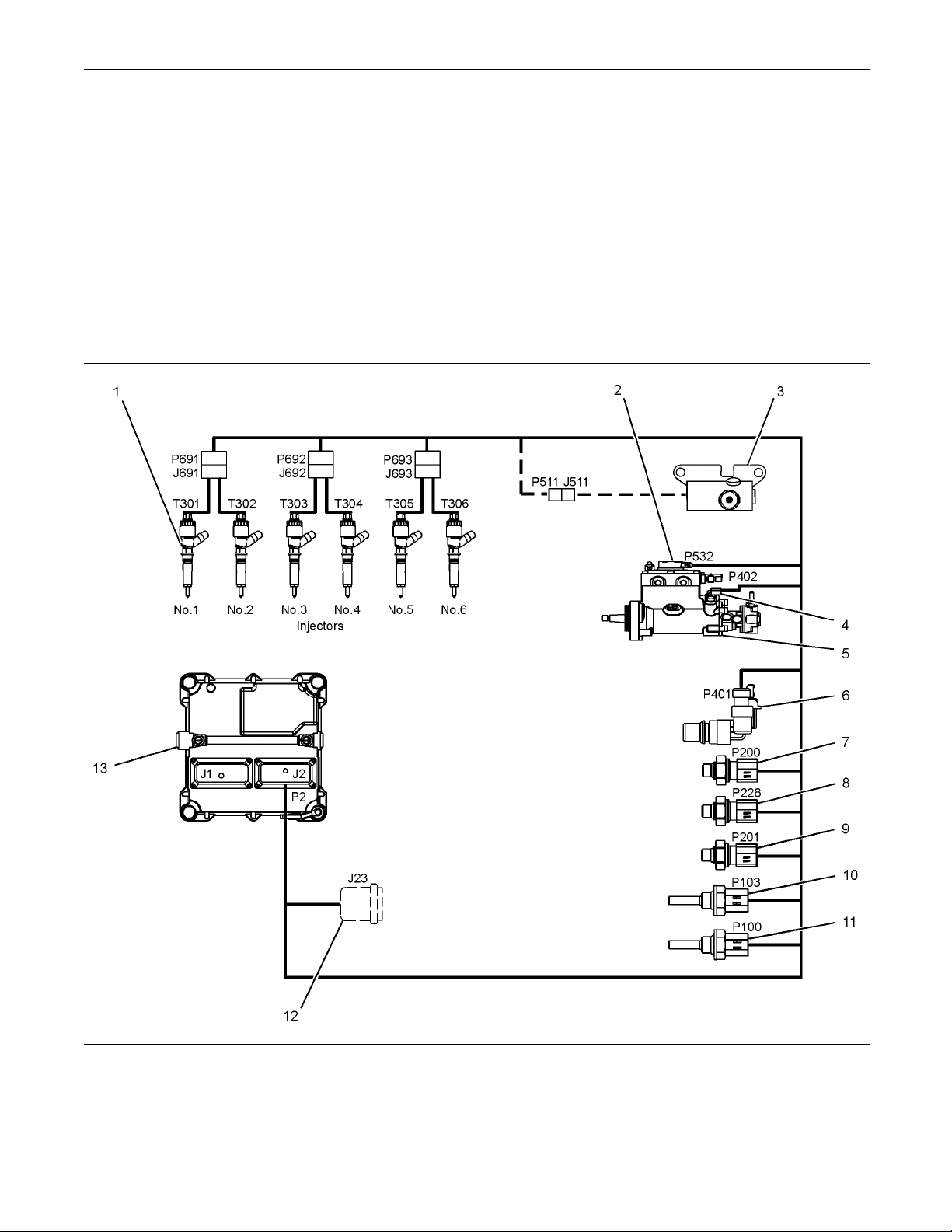
lustration 1
Il
(1) Electronic Unit Injector
(2) Solenoid for the Fuel Rail Pump
(3) Wastegate Regulator (if equipped)
(4) Secondary S peed/Timing Sensor
(5) Fuel Rail Pump
(6) Primary Spee d/Timing Sensor
(7) Intake Manifold Pressure Sensor
(8) Fuel Rail Pressure S ensor
(9) Engine O il Pressure Sensor
(10) Intake Manifold Temperature Sensor
(11) Coolant Temperature Sensor
(12) Diagnostic Connector (if equipped)
(13) Electronic Control M odule (ECM)
g01808033
Page 6

This document is printed from SPI². Not for RESALE
6 KENR6201-01
Troubleshooting Section
The 1 106D engine was designed for electronic
control. The en
(ECM), a fuel rail pump and electronic unit injectors.
All of these items are electronically controlled. There
arealsoanumb
engines can be equipped with an electronically
controlled wastegate for the turbocharger. The ECM
controls the
the software within the ECM and the inputs from the
various sensors. The software contains parameters
that contro
include all of the operating maps and customer
selected parameters.
The electronic system consists of the ECM, the
engine sensors and inputs from the parent machine.
The ECM is t
is the software for the computer. The personality
module defines the following characteristics of the
engine:
Engine power
•
Torque curves
•
Engine sp
•
Engine Noise
•
gine has an Electronic Control Module
er of engine sensors. Turbocharged
engine operating parameters through
l the engine operation. The parameters
he computer. The personality module
eed (rpm)
At start-up, the ECM determines the top center
position of the
speed/timing sensor in the fuel rail pump. The ECM
decides when fuel injection should occur relative to
the top center
performance by control of each of the electronic
unit injectors so that the required amount of fuel is
injected at t
electronic unit injectors are supplied high pressure
fuel from the fuel rail. The ECM also provides the
signal to th
solenoid in the fuel rail pump controls a valve in the
fuel rail pump. This valve controls the pressure in
the fuel rai
is diverted away from the fuel rail pump back to the
fuel tank.
The ECM adjusts injection timing and fuel pressure
for the best engine performance, the best fuel
economy an
Theactualtimingcanbeviewedwithanelectronic
service tool. Also, the desired timing can be viewed
with an el
number 1 cylinder from the secondary
position. The ECM optimizes engine
he precise point of the engine's cycle. The
e solenoid in the fuel rail pump. The
l. Fuel that is not required for the engine
d the best control of exhaust emissions.
ectronic service tool.
Fuel Injection
The personality module inside the ECM sets certain
limits on the amount of fuel that can be injected.
Smoke and Emissions
•
Engine
The ECM determines the injection timing, the amount
of fuel
manifold pressure if an electronically controlled
wastegate is installed on the turbocharger. These
decis
desired conditions at any given time.
The go
engine speed to the actual engine speed. The actual
engine speed is determined through the primary
spee
sensor. If the desired engine speed is greater than
the actual engine speed, the governor injects more
fuel
Speed Governor
that is delivered to the cylinders and the intake
ions are based on the actual conditions and the
vernor has software that compares the desired
d/timing sensor and the secondary speed/timing
in order to increase engine speed.
Timing Considerations
Fuel injection timing is determined by the ECM after
considering input from the following components:
Engine coolant temperature sensor
•
e sensor for the intake manifold air temperature
Th
•
The sensor for the intake manifold pressure
•
Speed/timing sensors
•
The Fuel Ratio Control Limit is a limit that is based
on intake manifold air pressure and engine rpm. The
FRC Lim
to control the engine's exhaust emissions. When the
ECM senses a higher intake manifold air pressure,
the ECM
manifold air pressure indicates that there is more air
in the cylinder. When the ECM increases the FRC
Limit
The Rated Fuel Limit is a limit that is based on the
power
The Rated Fuel Limit enables the engine power and
torque outputs to conform to the power and torque
curv
These limits are in the personality module and these
limi
Dia
When the ECM detects an electronic system problem,
the
logs the diagnostic code in order to indicate the time
of the problem's occurrence. The ECM also logs the
nu
codes are provided in order to indicate that the ECM
has detected an electrical problem or an electronic
oblem with the engine control system. In some
pr
cases, the engine performance can be affected when
the condition that is causing the code exists.
it is used to control the air/fuel ratio in order
increases the FRC Limit. A higher intake
, the ECM allows more fuel into the cylinder.
rating of the engine and on the engine rpm.
es of a specific engine model.
ts cannot be changedby the operator.
gnostic Codes
ECM generates a diagnostic code. Also, the ECM
mber of occurrences of the problem. Diagnostic
peed control device
S
•
Page 7

This document is printed from SPI². Not for RESALE
KENR6201-01 7
Troubleshooting Section
If the operator indicates that a performance problem
occurs, the dia
of the problem. Use the electronic service tool to
access the diagnostic codes. The problem should
then be correc
gnostic code may indicate the cause
ted.
Event Codes
Event Codes are used to indicate that the ECM has
detected an abnormal engine operating condition.
The ECM will
This does not indicate an electrical malfunction
or an electronic malfunction. For example, if the
temperatur
than the permitted limit, then the ECM will detect the
condition. The ECM will then log an event code for
the condit
Programma
Certain parameters that affect the engine operation
may be cha
The parameters are stored in the ECM, and the
parameters are protected from unauthorized changes
by passwo
Configuration Parameters.
System C
factory. System Configuration Parameters affect
emissions or power ratings within the engine. Factory
passwor
must be used to change the System Configuration
Parameters.
log the occurrence of the event code.
e of the coolant in the engine is higher
ion.
ble Parameters
nged with electronic service tools.
rds. These parameters are System
onfiguration Parameters are set at the
ds must be obtained and factory passwords
Adaptive Trim – This is a software process that is
performed in th
that optimizes engine performance.
Alternating C
electric current that reverses direction at a regular
interval that is reoccurring.
Before Top Center (BTC) – BTC is the 180 degrees
of crankshaft rotation before the piston reaches the
top dead cen
rotation.
Breakout Ha
test harness that is designed to connect into the
engine harness. This connection allows a normal
circuit op
provides a Breakout T in order to measure the
signals.
Bypass Circuit – A bypass circuit is a circuit that is
used as a substitute circuit for an existing circuit. A
bypass ci
CAN Data Link (see also J1939 CAN Data Link) –
The CAN Da
port that is used for communication with other
microprocessor based devices.
Code – Refer to “Diagnostic Code” or “Event Code”.
Communi
communication adapter provides a communication
link between the ECM and the electronic service tool.
e Electronic Control Module (ECM)
urrent (AC) – Alternating current is an
ter position in the normal direction of
rness – A breakout harness is a
eration and the connection simultaneously
rcuit is typically used as a test circuit.
ta Link is a serial communications
cation Adapter Tool – The
Passwords
System Configuration Parameters are protected by
factory passwords. Factory passwords are calculated
onaco
Perkins distributors. Since factory passwords contain
alphabetic characters, only an electronic service
tool
System C onfiguration Parameters affect the power
rating or the emissions.
Refer to Troubleshooting, “Programming Parameters”
and Troubleshooting, “Factory Passwords”.
mputer system that is available only to
may change System Configuration Parameters.
i03805350
Glossary
Active Diagnostic Code – An active diagnostic
code alerts the operator or the service technician that
an electronic system malfunction is currently present.
Refer to the term “Diagnostic Code” in this glossary.
Component Identifier (CID) – TheCIDisanumber
that identifies the specific component of the electronic
ol system that has experienced a diagnostic
contr
code.
nt Temperature Sensor – The coolant
Coola
temperature sensor detects the engine coolant
temperature for all normal operating conditions and
ngine monitoring.
for e
Data Link – The Data Link is a serial communication
that is used for communication with other devices
port
such as the electronic service tool.
ate – Certain engine conditions will generate
Der
event codes. Also, engine derates may be applied.
The map for the engine derate is programmed into
ECM software. The derate can be one or more of
the
3 types: reduction of rated power, reduction of rated
engine speed, and reduction of rated machine speed
r OEM products.
fo
Desired Engine Speed – The desired engine speed
input to the electronic governor within the ECM.
is
The electronic governor uses the signal from the
throttle position sensor, the engine speed/timing
ensor, and other sensors in order to determine the
s
desired engine speed.
Page 8

This document is printed from SPI². Not for RESALE
8 KENR6201-01
Troubleshooting Section
Diagnostic Code – A diagnostic code is sometimes
referred to as a
electronic system malfunction.
Digital Senso
from the ECM is used as ground for the digital
sensors.
Digital Sensors – Digital sensors produce a pulse
width modulated signal. Digital sensors are supplied
with power f
Digital Sensor Supply – The power supply for the
digital sen
Direct Current (DC) – Direct current is the type of
current th
DT, DT Connector, or Deutsch DT – This is a
type of con
connectors are manufactured by Deutsch.
Duty Cycl
Electronic Engine Control – The electronic
engine co
The electronic engine control monitors the engine
operation under all conditions. The electronic engine
control
conditions.
Electro
is the control computer of the engine. The ECM
provides power to the electronics. The ECM monitors
data th
ECM acts as a governor in order to control the speed
and the power of the engine.
also controls the engine operation under all
nic Control Module (ECM) – The ECM
at is input from the sensors of the engine. The
fault code. These codes indicate an
rReturn –The common line (ground)
rom the ECM.
sors is provided by the ECM.
at flows consistently in only one direction.
nector that is used on the engine. The
e–Refer to “Pulse Width Modulation”.
ntrol is a complete electronic system.
Event Code – An event code may be activated
in order to indi
condition. These codes usually indicate a mechanical
problem instead of an electrical system problem.
Failure Mode Identifier (FMI) – This identifier
indicates the type of failure that is associated with
the componen
SAE practice of J1587 diagnostics. The FMI follows
the parameter identifier (PID) in the descriptions of
the fault co
the following list.
0–The data i
operational range.
1–The data
operational range.
2–The data
3–The voltage is above normal or the voltage is
shorted h
4–The voltage is below normal or the voltage is
shorted l
5–The current is below normal or the circuit is open.
6–The current is above normal or the circuit is
grounded.
7–The mechanical system is not responding
properly.
8–There is an abnormal frequency, an abnormal
pulse width, or an abnormal time period.
cate an abnormal engine operating
t. The FMI has been adopted from the
de. The descriptions of the FMIs are in
s valid but the data is above the normal
isvalidbutthedataisbelowthenormal
is erratic, intermitte nt, or incorrect.
igh.
ow.
Electronic Service Tool – The electronic service
tool allows a computer (PC) to communicate with the
ECM.
Engine Monitoring – Engine Monitoring is the part
e electronic engine control that monitors the
of th
sensors. This also warns the operator of detected
problems.
Engine Oil Pressure Sensor – The engine oil
pressure sensor measures engine oil pressure. The
sor sends an electronic signal to the ECM that is
sen
dependent on the engine oil pressure.
ine Speed/Timing Sensor – An engine
Eng
speed/timing sensor is a hall effect switch that
provides a signal to the ECM. The ECM interprets
is signal as the crankshaft position and the engine
th
speed. Two sensors are used to provide the speed
and timing signals to the ECM. The primary sensor
associated with the crankshaft and the secondary
is
sensor is associated with the camshaft.
ther Relay – Theetherrelayisusedtoactuatethe
E
ether injection system. The ECM controls the relay.
9–There has been an abnormal update.
10 – Th
11 – The failure mode is not identifiable.
12 – The device or the component is damaged.
13 – T
14 and 15 – These locations are reserved for a
fut
Flash Programming – Flash programming is the
met
an electronic service tool over the data link instead
of replacing components.
Fuel Injector E-Trim – Fuel injector E-trim is a
software process that allows precise control of fuel
in
the ECM for each fuel injector. With the use of the
electronic service tool, the service technician can
ead status information for the E-Trim. Data for
r
E-Trimcanalsobeprogrammed.
ere is an abnormal rate of change.
he device or the component is not calibrated.
ure assignment.
hod of programming or updating an ECM with
jectors by parameters that are programmed into
Page 9

This document is printed from SPI². Not for RESALE
KENR6201-01 9
Troubleshooting Section
FRC – See “Fuel Ratio Control”.
Fuel Pump – See “Fuel Rail Pump”.
Fuel Rail – Thi
the High Pressure Fuel Rail. The fuel rail supplies
fuel to the electronic unit injectors. The fuel rail pump
and the fuel r
in order to maintain the desired fuel pressure in the
fuel rail. This pressure is determined by calibration
of the engin
emissions and performance requirements.
FuelRailPr
sensor sends an electronic signal to the ECM that is
dependent on the pressure of the fuel in the fuel rail.
Fuel Rail Pump – This item is sometimes referred
toastheHighPressureFuelRailPump.Thisisa
device tha
rail (high pressure fuel rail).
Fuel Rail
referred to as the High Pressure Fuel Rail Pump
Solenoid Valve. This is a control device in the high
pressure
pressure in the fuel rail by using this valve to divert
excess fuel from the pump to the fuel tank.
Fuel Ratio Control (FRC) – The FRC is a limit that
is based on the control of the ratio of the fuel to air.
The FRC i
When the ECM senses a higher intake manifold
air pressure (more air into the cylinder), the FRC
ses the FRC Limit (more fuel into the cylinder).
increa
Full Load Setting (FLS) – The FLS is the number
epresents the fuel system adjustment. This
that r
adjustment is made at the factory in order to fine tune
thefuelsystem.Thecorrectvalueforthisparameter
mped on the engine information ratings plate.
is sta
This parameter must be programmed.
Plug – The glow plug is an optional starting aid
Glow
for cold conditions. One glow plug is installed in each
combustion chamber in order to improve the ability of
ngine to start. The ECM uses information from
the e
the engine sensors such as the engine temperature
to determine when the glow plug relay must provide
er to each glow plug. Each of the glow plugs
pow
then provides a very hot surface in the combustion
chamber in order to vaporize the mixture of air and
l. This improves ignition during the compression
fue
stroke of the cylinder.
ow Plug Relay – The glow plug relay is controlled
Gl
by the ECM in order to provide high current to the
glow plugs that are used in the starting aid system.
Harness – The harness is the bundle of wiring
(loom) that connects all components of the electronic
ystem.
s
s item is sometimes referred to as
ail pressure sensor work with the ECM
e in order to enable the engine to meet
essure Sensor – Thefuelrailpressure
t supplies fuel under pressure to the fuel
Pump Solenoid Valve – This is sometimes
fuel rail pump. The ECM controls the
s used for purposes of emission control.
Hertz (Hz) – Hertz is the measure of electrical
frequency in cy
High Pressure Fuel Rail Pump – See “Fuel Rail
Pump”.
High Pressure Fuel Rail Pump Solenoid Valve –
See “Fuel Rai
High Pressure Fuel Rail – See “Fuel Rail”.
Injector Codes – The injector codes or injector trim
codes are numeric codes or alphanumeric codes
that are etc
unit injectors. These codes are used to fine tune the
fuel delivery.
Injector Trim Files – Injector trim files are
downloaded from a disk to the ECM. The injector trim
files compe
the electronic unit injector. The serial number for the
electronic unit injector must be obtained in order to
retrieve
Intake Manifold Air Temperature Sensor – The
intake ma
air temperature in the intake manifold. The ECM
monitors the air temperature and other data in the
intake m
other performance functions.
Intake M
Manifold Pressure Sensor measures the pressure
in the intake manifold. The pressure in the intake
manifo
the engine (atmospheric pressure). The difference
in pressure may be caused by an increase in air
press
Integrated Electronic Controls – The engine is
desig
part of the system. The engine will not operate
without the electronic controls.
J1939 CAN Data Link – This data link is a SAE
standard diagnostic communications data link that
is us
electronic devices.
Log
codes are codes which are stored in the memory.
These codes are meant to be an indicator of possible
cau
term “Diagnostic Code” in this glossary for more
information.
OEM – OEM is an abbreviation for the Original
Equipment Manufacturer. This is the manufacturer of
th
the correct injector trim file.
ld may be different to the pressure outside
ure by a turbocharger (if equipped).
ned with the electronic controls as a necessary
ed to communicate between the ECM and the
ged Diagnostic Codes – Logged diagnostic
ses for intermittent problems. Refer to the
e machine or the vehicle that uses the engine.
cles per second.
l Pump Solenoid Valve”.
hed or stamped on individual electronic
nsate for variances in manufacturing of
nifold air temperature sensor detects the
anifold in order to adjust injection timing and
anifold Pressure Sensor –
The Intake
Page 10
This document is printed from SPI². Not for RESALE
10 KENR6201-01
Troubleshooting Section
Open Circuit – An open circuit is a condition that is
caused by an ope
or a connection that is broken. When this condition
exists, the signal or the supply voltage can no longer
reach the inte
Parameter – A parameter is a value or a limit that
is programma
characteristics or behaviors of the engine.
Password – A
characters or a group of alphanumeric characters
that is designed to restrict access to parameters. The
electronic
to change some parameters (Factory Passwords).
Refer to Troubleshooting, “Factory Passwords” for
more infor
Personality Module – This module is software
that is ins
instructions (software) for the ECM and the module
contains the performance maps for a specific engine.
The perso
through flash programming.
Power Cyc
of cycling the keyswitch from any position to the OFF
position, and to the START/RUN position.
Primary Speed/Timing Sensor – This sensor
determines the position of the crankshaft during
engine o
sensor fails during engine operation, the secondary
speed/timing sensor is used to provide the signal.
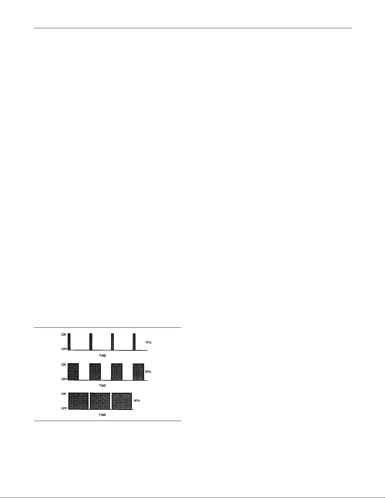
Pulse Width Modulation (PWM) – The PWM is a
signal that consists of pulses that are of variable
width
of “TIME ON” versus total “TIME OFF” can be varied.
Thisratioisalsoreferredtoasadutycycle.
system requires correct passwords in order
mation.
ide the ECM. The module contains all the
nality module may be reprogrammed
peration. If the primary speed/timing
. These pulses occur at fixed intervals. The ratio
n switch, or by an electrical wire
nded destination.
ble. This helps determine specific
password is a group of numeric
ling – Power cycling refers to the action
Rated Fuel Limit – This is a limit that is based on
the power ratin
The Rated Fuel Limit enables the engine power and
torque outputs to conform to the power and torque
curves of a spe
in the personality module and these limits cannot be
changed.
Reference Voltage – Reference voltage is a
regulated voltage and a steady voltage that is
supplied by
voltage is used by the sensor to generate a signal
voltage.
Relay – A relay is an electromechanical switch. A
flow of electricity in one circuit is used to control the
flow of elec
voltage is applied to a relay in order to switch a much
larger current or voltage.
Secondary Speed/Timing Sensor – This sensor
determines the position of the camshaft during engine
operatio
during engine operation, the secondary speed/timing
sensor is used to provide the signal.
Sensor – A sensor is a device that is used to
detect the current value of pressure or temperature,
or mecha
detected is converted into an electrical signal.
Short Ci
an electrical circuit that is inadvertently connected to
an undesirable point. An example of a short circuit
is a wir
this rubbing eventually wears off the wire insulation.
Electrical contact with the frame is made and a short
circu
Signal – The signal is a voltage or a waveform that
is use
asensortotheECM.
e which rubs against a vehicle frame and
it results.
d in order to transmit information typically from
g of the engine and on the engine rpm.
cific engine model. These limits are
the ECM to a sensor. The reference
tricity in another circuit. A small current or
n. If the primary speed/timing sensor fails
nical movement. The information that is
rcuit – A short circuit is a condition that has
dDemandInput –The speed demand input is
Spee
a signal that is sent to the ECM in order to calculate
desired engine speed.
Supply Voltage – The supply voltage is a continuous
voltage that is supplied to a component in order to
vide the electrical power that is required for the
pro
component to operate. The power may be generated
by the ECM or the power may be battery voltage that
upplied by the engine wiring.
is s
System Configuration Parameters – System
nfiguration parameters are parameters that affect
co
emissions and/or operating characteristics of the
engine.
Illustration 2
g00284479
Page 11

This document is printed from SPI². Not for RESALE
KENR6201-01 11
Troubleshooting Section
Tattletale – Certain parameters that affect the
operation of th
These parameters can be changed by use of the
electronic service tool. The tattletale logs the number
of changes tha
ThetattletaleisstoredintheECM.
Throttle Pos
interpretation by the ECM of the signal from the
speed controller.
Timing Calibration – The timing calibration is the
adjustment of an electrical signal. This adjustment is
made in orde
camshaft and the engine speed/timing sensors or
between the crankshaft and the engine speed/timing
sensors.
Top Center Position – The top center position refers
to the cran
position is at the highest point of travel. The engine
must be turned in the normal direction of rotation in
order to r
T otal Tattletale – The total tattletale is the total
number of
stored in the ECM.
Wastega
engine that controls the maximum boost pressure
that is provided to the inlet manifold.
Wastegate Regulator (if equipped) – The
wastegate regulator controls the pressure in the
manifold to a value that is determined by the
intake
ECM. The wastegate regulator provides the interface
between the ECM and the mechanical system that
ates intake manifold pressure to the desired
regul
value that is determined by the software.
e engine are stored in the ECM.
t have been made to the parameter.
ition – The throttle position is the
r to correct the timing error between the
kshaft position when the engine piston
each this point.
changes to all the parameters that are
te – This is a device in a turbocharged
Required Service Tools
Table 1
Required Service Tools
Part Number Description
CH11155
2900A019
27610285
-
Two short jumper wires are needed to check the
continuity of some wiring harness circuits by shorting
two adjacent terminals together in a connector. A
long extension wire may also be needed to check the
continuity of some wiring harness circuits.
Crimp Tool (1
Wire Removal Tool
Removal To ol
Suitable Digital Multimeter
2−AWG TO 18−AWG)
Optional Service Tools
Table 2 lists the optional service tools that can be
used when the engine is serviced.
Table 2
Part Number Description
U5MK1092
-
or
-
-
-
28170107
2900A038
Spoon Probe Kit(MULTIMETER)
Suitable Digital Pressure Indicator
or
Engine Pressure Group
ble Battery Load Tester
Suita
Suitable Temperature Adapter
(MULTIMETER)
Bypass Harness As
Harness As
i02517580
Electronic Service Tools
Perkins electronic service tools are designed to help
the service technician:
Retrieve diagnostic codes.
•
Diagnose electrical problems.
•
Read parameters.
•
Program parameters.
•
Install trim files.
•
Perkins Electronic Service Tool
The Perkins Electronic Service Tool can display the
following information:
Status of all pressure sensors and temperature
•
sensors
Programmable parameter settings
•
Active diagnostic codes and logged diagnostic
•
codes
Logged events
•
Histograms
•
The Electronic Service Tool can also be used to
perform the following functions:
Diagnostic tests
•
Page 12
This document is printed from SPI². Not for RESALE
12 KENR6201-01
Troubleshooting Section
Sensor calibrations
•
Programming of flash files
•
Parameter pro
•
Copy configuration function for ECM replacement
•
Data logging
•
Graphs (rea
•
gramming
ltime)
Table 3 lists the service tools that are required in
order to use
Table 3
Service Tools for the Use of the Electronic
Part
Number
-
-
27610251
27610164
(1)
Refer to Perkins Engine Company Limited.
the Electronic Service Tool.
Service Tool
(1)
(1)
Single Use Program License
Data Subscription for All Engines
Communication Adapter (Electronic
Service
Adapter Cable As
Tool to ECM interface)
Description
Connecting the Electronic Service Tool
and the Communi
cation Adapter II
Note: For more information regarding the use of the
Electronic Service Tool and the PC requirements
for the Electronic Service Tool, refer to the
documentation that accompanies your Perkins
Electronic Service Tool software.
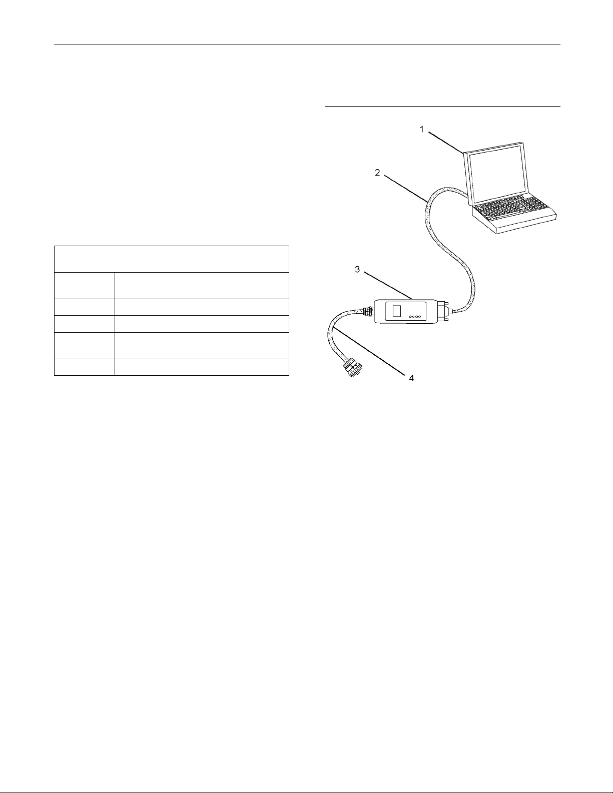
Illustration 3
(1) Personal Computer (PC)
(2) Adapter Cable (Computer Serial Port)
(3) Communication Adapter II
(4) Adapter Cable Assembly
g01121866
Note: Items (2), (3) and (4) are part of the
Communication Adapter II kit.
Use the following procedure in order to connect
the Electronic Service Tool and the Communication
Adapter II.
1. Turn the keyswitch to the OFF position.
2. Connect cable (2) between the “COMPUTER”
end of communication adapter (3) and the RS232
serial port of PC (1).
Note: The Adapter Cable Assembly (4) is required to
connect to the USB port on computers that are not
equipped with a RS232 serial port.
3. Connect cable (4) between the “DATA LINK” end
of communication adapter (3) and the service tool
connector.
4. Place the keyswitch in the ON position. If the
Electronic Service Tool and the communication
adapter do not communicate with the Electronic
Control Module (ECM), refer to the diagnostic
procedure Troubleshooting, “Electronic Service
Tool Will Not Communicate With ECM”.
Page 13

This document is printed from SPI². Not for RESALE
KENR6201-01 13
Troubleshooting Section
i03787449
Indicator Lamps
Indicator Lam
The functions of the indicator lamps are designed to
display the m
minimum number of lamps.
Eight lamps
lamp and the “Warning” lamp will normally be
installed in the application. Dedicated optional lamps
for other it
optional lamps are “Low oil pressure”, “Overspeed”,
“High Coolant Temperature”, “Diagnostic”, “Derate”
and “Maint
The “Shutdown” lamp and the “Warning” lamp can
also be us
the “Flash Code” feature. The “Flash Code” feature
can be used to indicate all active diagnostic codes
and logge
Functio
aximum amount of information on the
are available as options. The “Shutdown”
ems may also be installed. The remaining
enance”.
ed to indicate a diagnostic code by use of
d diagnostic codes.
ns of the Lamps
ps
On – Thelampwillcomeonwhena“highcoolant
temperature” e
and the “Shutdown” lamp may also come on.
Overspeed Lam
Lamp check – When the keyswitch is turned to
the ON positi
seconds. The lamp will then go off unless the engine
overspeeds.
On – Thelampwillcomeonwhenan“engine
overspeed” event is detected. The “Warning” lamp
and the “Shu
vent is detected. The “Warning” lamp
p
on,thelampwillcomeonfortwo
tdown” lamp may also come on.
Derate Lamp
Lamp check – When the keyswitch is turned to the
ON position, the lamp will come on for two seconds.
On – Thelampwillcomeonwhentheengineis
derated.
Diagnostic Lamp
Lamp che
ON position, the lamp will come on for two seconds.
ck – When the keyswitch is turned to the
Shutdown Lamp
Lamp check – When the keyswitch is turned to the
ON position, the lamp will come on for two seconds.
The lam
warning.
On – Th
the engine protection strategy has been reached.
Warni
Lamp check – When the keyswitch is turned to the
ON po
Thelampwillthengooffunlessthereisanactive
warning.
On – Thelampwillbeonwhenthewarninglevel
has been reached.
pwillthengooffunlessthereisanactive
elampwillbeonwhentheshutdownlevelin
ng Lamp
sition, the lamp will come on for two seconds.
Low Oil Pressure
pcheck –When the keyswitch is turned to the
Lam
ON position, the lamp will come on for two seconds.
– Thelampwillcomeonwhenalowoilpressure
On
event is detected. The “Warning” lamp and the
“Shutdown” lamp may also come on.
Flashin
code or an event code is active. Refer to “Flash
Codes”.
g–Thelampwillflashwhenadiagnostic
Maintenance Lamp
Lamp ch
ON position, the lamp will come on for two seconds.
The lamp will then go off unless maintenance is due.
On – The lamp will come on when maintenance is
due.
eck – When the keyswitch is turned to the
Color of Lamps
Typically, the “Shutdown” lamp is colored red and the
“Warning” lamp is colored amber. The other lamps
ptional.
are o
High Coolant Temperature Lamp
amp check – When the keyswitch is turned to the
L
ON position, the lamp will come on for two seconds.
Page 14

This document is printed from SPI². Not for RESALE
14 KENR6201-01
Troubleshooting Section
Operation of the I ndi cator Lamps
Table 4
Warning
Lamp
(Alert
Lamp)
On On On On
Off Off Off Off
On Off Flashing Off
On Off Flashi
On On Flashing Off
Off Off
Shutdown
Lamp
(Action
Lamp)
Diagnostic
Lamp
ng
Flashing
Derate
Lamp
On
Off
Lamp State Description of the Indication Engine State
Lamp Check
No Faults With the engine in operation, there
Warning
(Warning
only)
Derate
ng
(Warni
and Derate)
Engine
down
shut
(Warning
and
tdown)
shu
Diagnostic
(Diagnostic
ly)
on
When the keyswitch is switched on,
the lamps come on for a period of
2 seconds and the lamps will then
go off.
are no active warnings, diagnostic
codes or event codes.
If the warn
during engine operation, and the
diagnostic lamp is flashing , the
lamps ind
the warning values for the engine
protection strategy have been
exceeded
active event code. However, the
value has not been exceeded to a
level th
shutdown.
If both the warning lamp and the
derate lamp come on during engine
operation, and the diagnostic lamp
is flashing, the lamps indicate that
one or more of the values for the
engine protection strategy have
been exceeded beyond the level
that will cause an engine derate.
If both the warning lamp and
the shutdown lamp come on
during engine operation, and the
diagnostic lamp is flashing, the
lamps indicate that one or more
of the shutdown values for the
engine protection strategy has
been exceeded and there is an
active event code.
When the diagnostic lamp flashes
during operation of the engine,
the lamp indicates that an active
diagnostic code (an electrical fault)
is present. However, the diagnostic
code is not serious enough to
cause a derate or a shutdown.
ing lamp comes on
icate that one or more of
and that there is an
at will cause a derate or a
The keyswitch is
on but the engine
has not yet been
cranked.
The engine is
operating with no
detected faults.
The engine
is operating
normally.
However, there is
oneormoreofthe
monitored engine
parameters that
are outside of
the range that is
acceptable.
The engine
ating.
is oper
However, one
or more of the
red engine
monito
parameters is
outside of the
table range.
accep
The acceptable
range has been
ded to
excee
alevelwhich
requires a warning
nengine
and a
derate.
The engine is
er shutdown
eith
or an engine
shutdown is
inent.
imm
One or more
monitored engine
ameters have
par
exceeded the
limit for an engine
utdown.
sh
The engine is
operating but
ere is one or
th
more faults with
the electronic
ystem for the
s
engine.
(continued)
Page 15
This document is printed from SPI². Not for RESALE
KENR6201-01 15
Troubleshooting Section
(Table 4, contd
Off Off Flashing On
Off On Flashing Off
)
Derate
(Diagnostic
and Derate)
Engine
Shutdown
Flash Codes
The “Flash Code” feature is used to flash the two digit
code of all active diagnostic and event codes. Refer
to the Troubleshooting Guide, “Diagnostic Codes” for
the flash code that is related to the diagnostic code
or an event.
If the derate lamp comes on
during engine operation, and
the diagnostic lamp is flashing,
the lamps indicate that an active
diagnostic code (an electrical fault)
is present. The diagnostic code is
serious enough to cause an engine
derate.
If the shutdown lamp comes on
during engine operation, and the
diagnostic lamp is flashing, this
indicates that an active diagnostic
code (an electrical fault) is present.
The diagnostic code is serious
enough to cause the engine to
shutdown.
The engine
is operating.
However, an
active diagno
code is causing
an engine derate.
The engine is
either shutdown
or an engine
shutdown is
imminent. A
serious diagnostic
code is active.
stic
When a diagnostic code or an event code is active
or logged, the diagnostic lamp will flash repeatedly in
order to indicate the codes.
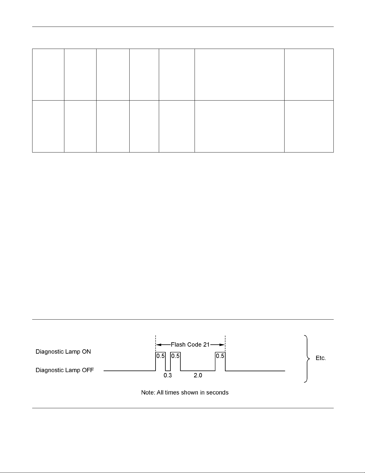
Each flash will be on for half a second and off for 300
milliseconds. The “Diagnostic” lamp will remain off for
two seconds between each digit of a code. If there
is more than one diagnostic code, the “Diagnostic”
lamp will go off for five seconds. The lamp will then
flash in order to indicate the next code.
As an example, an active diagnostic code of “21” is
indicated by the “Diagnostic” lamp coming on for 500
ms, then off for 300 ms, then on for 500 ms, then off
for 2000 ms, then on for 500 ms and then off.
Illustration 4
Once all codes have been flashed, the “Diagnostic”
lamp will go off for a period of 15 seconds before
Note: Flash codes are always sent in ascending
numerical order.
g02048816
starting the sequence again.
Page 16

This document is printed from SPI². Not for RESALE
16 KENR6201-01
Troubleshooting Section
i03805671
Replacing the ECM
NOTICE
Care must be taken to ensure that fluids are contained
during performance of inspection, maintenance, testing, adjust
collect the fluid with suitable containers before opening any compartment or disassembling any component contai
Dispose of all fluids according to local regulations and
mandates.
Keep all parts clean from contaminants.
Contaminants may cause rapid wear and shortened
component life.
The engine is equipped with an Electronic Control
Module (ECM). The ECM contains no moving parts.
Follow
in order to be sure that replacing the ECM will correct
the problem. Verify that the suspect ECM is the
cause o
ing and repair of the product. Be prepared to
ning fluids.
NOTICE
the troubleshooting procedures in this manual
f the problem.
Note: When a new ECM is not available, an ECM
canbeusedfrom
The ECM must have the same serial number
suffix. Ensure that the replacement ECM and the
part number fo
ECM. Be sure to record the parameters from the
replacement ECM. Use the “Copy Configuration ECM
Replacement
If the flash file and engine application are not matched,
engine damage may result.
Perform the following procedure in order to replace
the ECM.
1. Connect the electronic service tool to the
diagnostic connector.
2. Use the “Copy Configuration ECM Replacement”
function from the electronic service tool. If the
“Copy Configuration” is successful, proceed to
Step 4. If the “Copy Configuration” failed, proceed
to Step 3.
Note: Record any Logged Faults and Events for your
records.
3. Record the following parameters:
an engine that is not in service.
rtheflash file match the suspect
” function in the electronic service tool.
NOTICE
Note: Ensure that the ECM is receiving power
at the ECM is properly grounded before
and th
replacement of the ECM is attempted. Refer to the
schematic diagram.
A test ECM can be used in order to determine if the
ECM on the engine is faulty. Install a test ECM in
e of the suspect ECM. Install the flash file with
plac
the correct part number into the test ECM. Program
the parameters for the test ECM. The parameters
match the parameters in the suspect ECM.
must
Refer to the following test steps for details. If the test
ECM resolves the problem, reconnect the suspect
. Verify that the problem returns. If the problem
ECM
returns, replace the ECM.
e: If an ECM is intended to be used as a test
Not
ECM, “Test ECM Mode” must be selected on the
electronic service tool before the engine serial
mber is entered.
nu
Use the electronic service tool to read the parameters
the suspect ECM. Record the parameters in
in
the suspect ECM. Install the flash file into the new
ECM. After the ECM is installed on the engine, the
arameters must be programmed into the new ECM.
p
Record all of th e parameters on the
•
“Configuration” screen.
Record all of the parameters on the “Throttle
•
Configuration” screen.
Record all of the p arameters on the “Mode
•
Configuration” screen.
Record the serial numbers of the electronic unit
•
injectors. The injector serial numbers are shown
on the “Injector Trim Calibration” screen.
Note: If the parameters cannot be read, the
parameters must be obtained elsewhere. Some
parameters are stamped on the engine information
plate, but most parameters must be obtained from
thePTMIdataonthePerkinsintranet.
4. Remove power from the ECM.
5. Remove the ECM. Refer to Disassembly and
Assembly, “Electronic Control Module - Remove
and Install”.
6. Install the replacement ECM. Refer to Disassembly
and Assembly, “Electronic Control Module Remove and Install”.
7. If the replacement ECM is intended to be used
as a test ECM, select “Test ECM Mode” on the
electronic service tool.
Page 17

This document is printed from SPI². Not for RESALE
KENR6201-01 17
Troubleshooting Section
8. Download the flash file.
a. Connect the electronic service tool to the
diagnostic connector.
b. Select “WinFlash” from the “Utilities” menu of
the electronic service tool.
c. Select the downloaded flash file.
9. If necessar
the rating interlock. To clear the rating interlock,
enter the factory password when the electronic
service too
ECM mode will also clear the rating interlock.
10. Use the ele
parameters. Perform the following procedure.
a. If the “Cop
successful, use the “Copy Configuration, ECM
Replacement” function to load the configuration
file into t
Note: During the following procedure, factory
password
b. If the “Copy Configuration” procedure failed,
configur
parameters should match the parameters from
step 3.
Perform the “Fuel System Verification Test”.
11. Check f
passwords are required to clear logged events.
y, use the electronic service tool to clear
lisfirst connected. Activating the Test
ctronic service tool to program the
yConfiguration” procedure was
he ECM.
s may be required.
e the parameters individually. The
or logged diagnostic codes. Factory
Self-Diagnostics
i03538621
Logged
•
Active Code – An active diagnostic code indicates
that an active fault has been detected by the control
system. Activ
Always service active codes prior to servicing logged
codes.
Logged Code – Every generated code is stored
in the permanent memory of the ECM. The codes
are logged f
cleared by use of the electronic service tool.
Event Code –
detection of an abnormal engine operating condition.
For example, an event code will be generated if the
oil pressu
indicates the symptom of a fault.
Logged cod
needed. The fault may have been temporary. The
fault may have been resolved since the logging of
the code.
to generate an active diagnostic code whenever a
component is disconnected. When the component is
reconnec
codes may be useful to help troubleshoot intermittent
faults. Logged codes can also be used to review the
perform
e codes require immediate attention.
or 100 operating hours unless a code is
An event code is generated by the
re is too low. In this case, the event code
es may not indicate that a repair is
If the system is powered, it is possible
ted, the code is no longer active. Logged
ance of the engine and the electronic system.
i03473503
Sensors and Electrical
Connectors
The Electronic Control Module (ECM) and the
sensors are located on the left side of the engine.
RefertoFigure5.
The Electronic Control Module (ECM) has the ability
to detect faults in the electronic system and with
engine operation. A self-diagnostic check is also
performed whenever power is applied to the ECM.
When a fault is detected, a code is generated. An
alarm may also be generated. There are two types
of codes:
Diagnostic codes
•
Event codes
•
Diagnostic Code – When a fault in the electronic
system is detected, the ECM generates a diagnostic
code. This indicates the specific fault in the circuitry.
Diagnostic codes can have two different states:
Active
•
Page 18
This document is printed from SPI². Not for RESALE
18 KENR6201-01
Troubleshooting Section
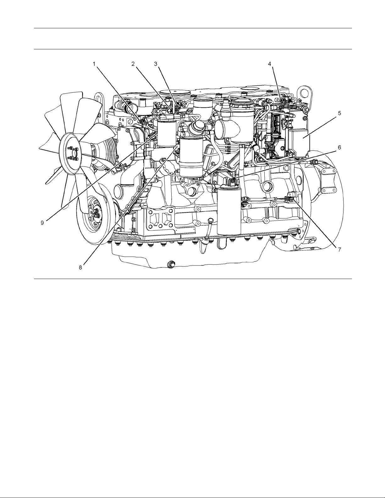
Illustration 5
Sensor locations
(1) Coolant Te mperature Sensor
(2) Intake Manifold Temperature Sensor
(3) Intake M anifold Pressure Sensor
(4) Fuel Rail Pressure S ensor
(5) Electronic Control Module (ECM)
(6) Oil Pressure S ensor
Note: If equipped, the wastegate regulator is installed
on the right side of the engine.
g01811780
(7) Primary S peed/Timing Senso r
(8) Secondary Speed/Timing Sens or
(9) Solenoid for the Fuel Rail Pump
Page 19
This document is printed from SPI². Not for RESALE
KENR6201-01 19
Troubleshooting Section
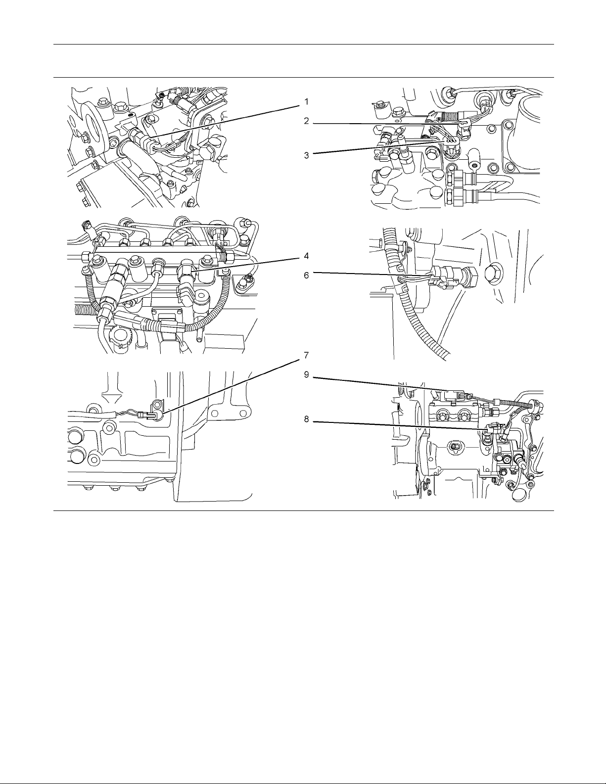
Illustration 6
Detailed views of the sensor locations
g01811835
Page 20

This document is printed from SPI². Not for RESALE
20 KENR6201-01
Troubleshooting Section
Table 5
Connector
P1
P2
P532
P402
P401
P201
P228
P200 Intake Manifold Pressure Sensor (3 Pin Connector)
P103 Intake Manifold Temperature Sensor (2 Pin Connector)
P100 Coolant Temperature Sensor (2 Pin Connector)
J23
P691/J691 Electronic Unit Injectors for No. 1 and No. 2 Cylinders (4 Pin
P692/J692 Electronic Unit Injectors for No. 3 and No. 4 Cylinders (4 Pin
P693/J693 Electronic Unit Injectors for No. 5 and No. 6 Cylinders (4 Pin
P511
Machine Harness to ECM Connector (64 Pin Connector)
Engine Harness to ECM Connector (64 Pin Connector)
Fuel Rail Pump Solenoid Connector (2 Pin Connector)
Secondary Speed/Timing Sensor (2 Pin Connector)
Primary Speed/Timing Sensor (2 Pin Connector)
Engine Oil Pressure Sensor (3 Pin Connector)
Fuel Rail Pressure Sensor (3 Pin Connector)
Diagnos
Connector)
Connector)
Connector)
Wastegate regulator (if equipped) (2 Pin Connector)
tic Connector (if equipped)
Function
Page 21
This document is printed from SPI². Not for RESALE
KENR6201-01 21
Troubleshooting Section
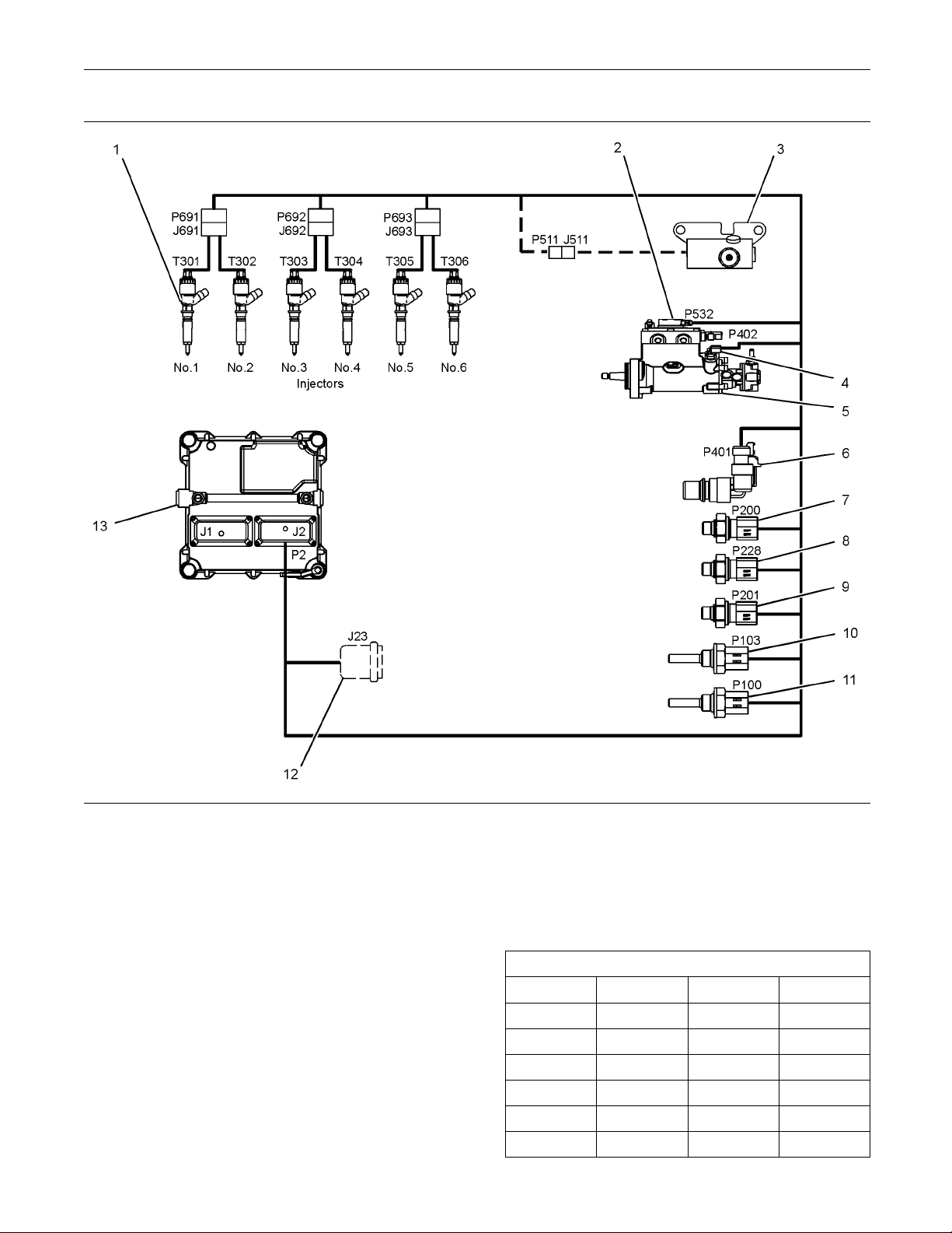
Illustration 7
(1) Electronic Unit Injector
(2) Solenoid for the Fuel Rail Pump
(3) Wastegate Regulator (if equipped)
(4) Secondary S peed/Timing Sensor
(5) Fuel Rail Pump
(6) Primary Spee d/Timing Sensor
(7) Intake Manifold Pressure Sensor
(8) Fuel Rail Pressure S ensor
(9) Engine O il Pressure Sensor
(10) Intake Manifold Temperature Sensor
Engine Wiring Information
Harness Wire Identification
i03805830
(11) Coolant Temperature Sensor
(12) Diagnostic Connector (if equipped)
(13) Electronic Control M odule (ECM)
Table 6
Color Codes for the Harness Wire
Color Code Color Color Code Color
BK Black BU Blue
BR Br
RD Red
own
PU Pu
GY Gray
g01808033
rple
Perkins identifies all wires with eleven solid colors.
The circuit number is stamped on the wire at a 25 mm
(1 inch) spacing. Table 6 lists the wire colors and the
OR Orange
YL Yellow PK Pink
WH White
color codes.
GN Green
Page 22

This document is printed from SPI². Not for RESALE
22 KENR6201-01
Troubleshooting Section
For example, a wire identification of F730-OR on
the schematic w
circuit number F730. F730-OR identifies the power
supply for the oil pressure sensor.
Note: Always replace a harness wire with the same
gauge of wire and with the same color code.
ould signify an orange wire with the
Page 23
This document is printed from SPI². Not for RESALE
KENR6201-01 23
Troubleshooting Section
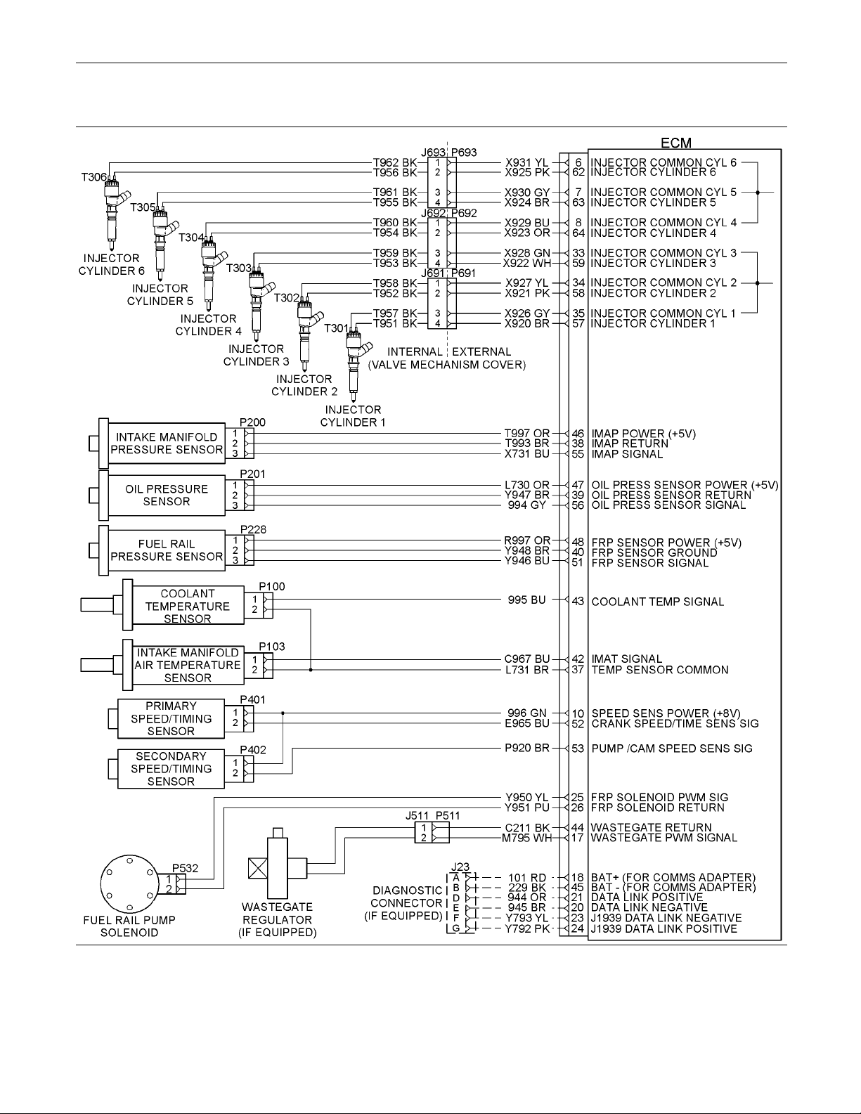
Schematic Diagrams
Illustration 8
hematic Diagram for the Engine Harness
Sc
g01782875
Page 24
This document is printed from SPI². Not for RESALE
24 KENR6201-01
Troubleshooting Section
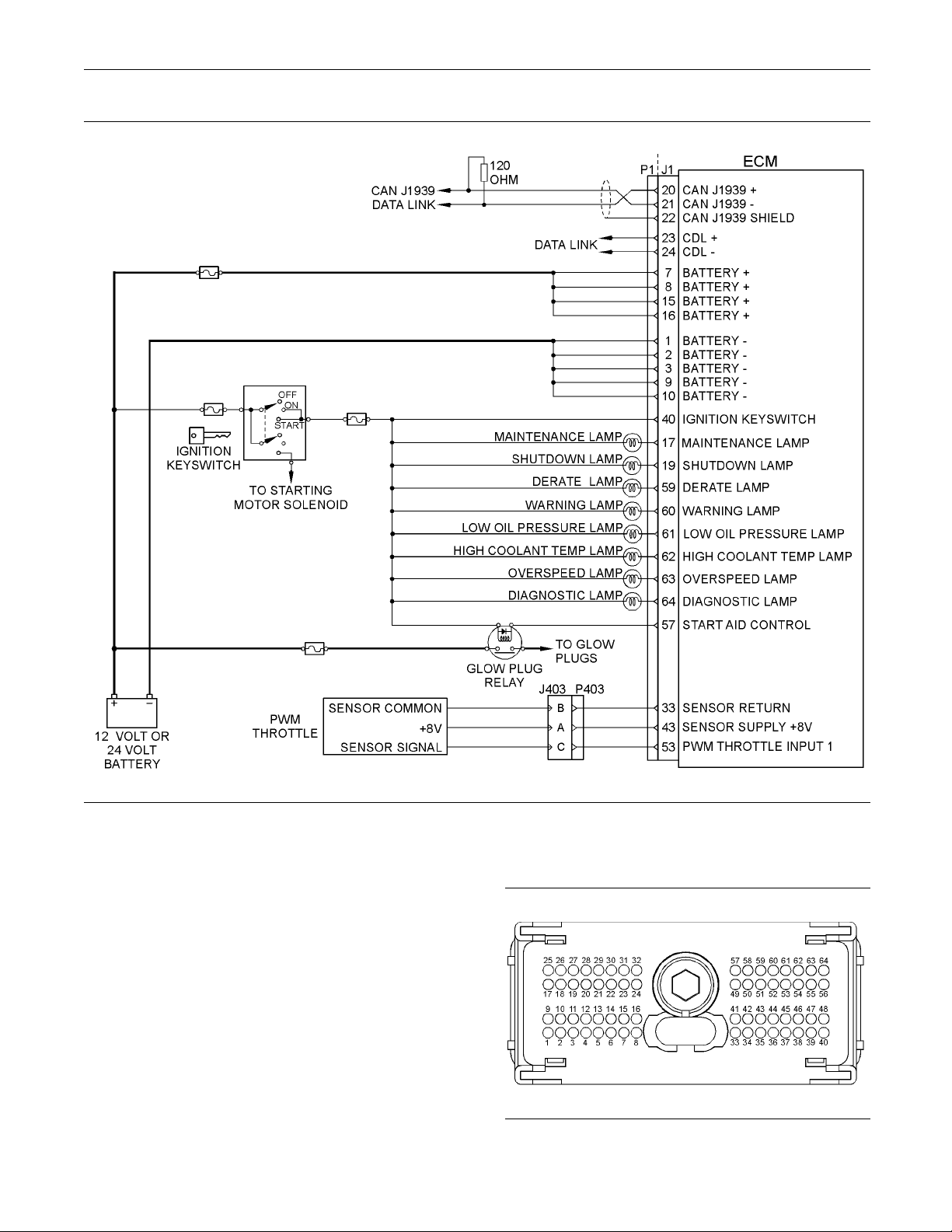
Illustration 9
Schematic Diagram for a Typical Application
i03434106
g02047353
ECM Harness Connector
Terminals
The Electronic Control Module (ECM) uses
connectors that have 64 terminals to interface to the
wiring harness.
Illustration 10
ayout of the Connector Pins (view from the rear)
L
g01784773
Page 25
This document is printed from SPI². Not for RESALE
KENR6201-01 25
Troubleshooting Section
Removal and Installation of the
Harness Connector Terminals
Terminal Removal
Table 7
Required Tools
Part Number Part Description Qty
27610285 Removal Tool 1
3. Insert the removal tool into the hole that is
adjacent to the
locking device.
Note: Make sur
the face of the connector.
4. Hold the tool
order to remove the terminal from the rear of the
connector (3).
5. Remove the removal tool from the face of the
connector (3).
Note: If a terminal must be replaced, part number
28170085 must be used.
terminal in order to release the
e that the tool stays perpendicular to
in position and gently pull the wire in
Terminal Insertion
1. Push the te
until the terminal engages with the locking device.
2. Gently pu
the terminal is retained by the locking device.
3. Install
components (2) into the sides of the connector (3).
rminal into the rear of the connector (3)
llonthewireinordertomakesurethat
the two terminal position assurance
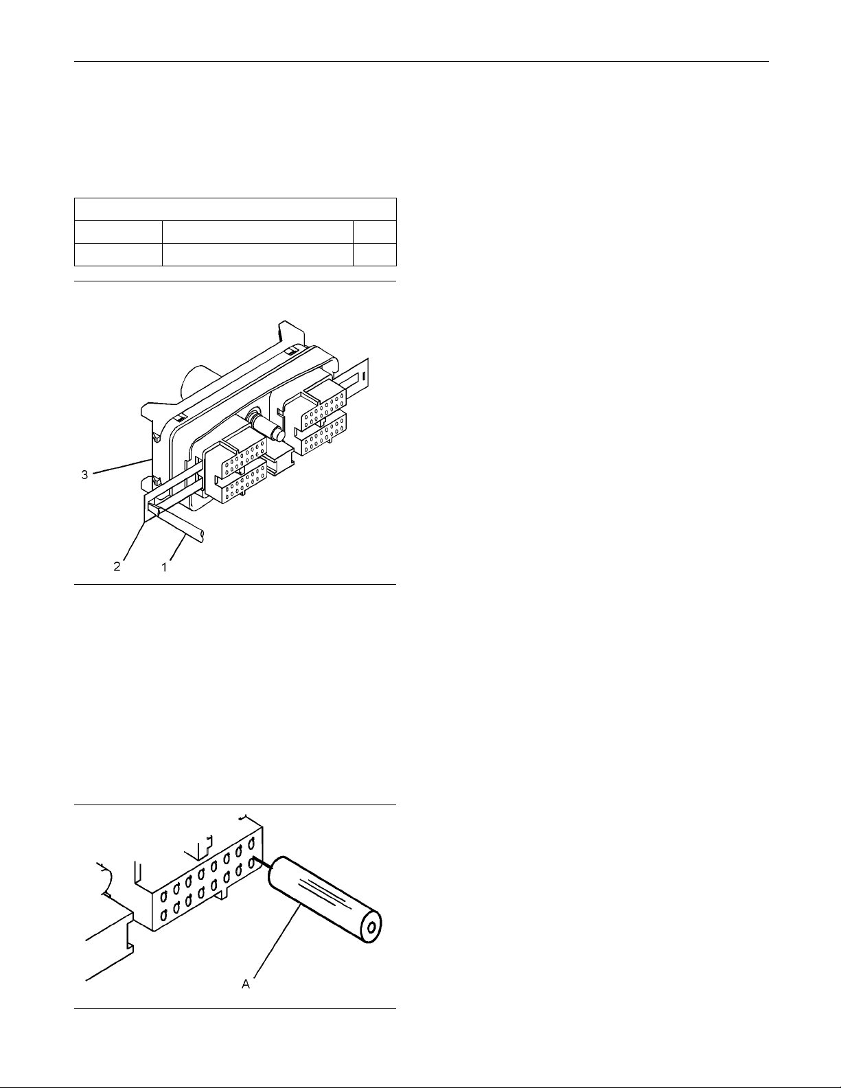
Illustration 11
Removal of Terminal Position Assurance Components
1. Remove the connector from the ECM. Refer to
Disassembly and Assembly, “Electronic Control
Module - Remove and Install”.
2. Use a screwdriver that has a flat blade (1) to
remove the two terminal position assurance
components (2) from the connector (3).
Note: Do not use the removal tool to remove the
terminal position assurance components.
g01784793
4. Connect
Disassembly and Assembly, “Electronic Control
Module - Remove and Install”.
the connector to the ECM. Refer to
Illustration 12
Removal Tool
g01784822
Page 26

This document is printed from SPI². Not for RESALE
26 KENR6201-01
Troubleshooting Section
Programming Pa
rameters
i02415216
Programming Parameters
Theelectronicservicetoolcanbeusedtoview
certain parameters that can affect the operation of the
engine. The electronic service tool can also be used
to change certain parameters. The parameters are
stored in the Electronic Control Module (ECM). Some
of the parameters are protected from unauthorized
changes by passwords. Parameters that can be
changed have a tattletale number. The tattletale
number shows if a parameter has been changed.
i0343420
Test ECM Mode
“Test EC
can be used to help troubleshoot an engine that may
have a fault in the Electronic Control Module (ECM).
This fe
test ECM. This feature eliminates the need to stock
atestECM.
M Mode” is a feature in the software that
ature allows a standard ECM to be used as a
Note: “Test ECM Mode” can only be activated if
the engine seri
programmed during normal operation of the ECM.
If the engine serial number is programmed and the
ECM is not in “T
be used as a test ECM.
6. Use the “Copy
electronic service tool to program the test ECM.
Note: If the
used, program the test ECM with the values from the
“Customer Specified Parameters Worksheet” and the
values from
7. Program the engine serial number into the test
ECM.
Note: The “Test ECM Mode” must be activated
4
before the
the ECM.
8. Verify th
When the “Test ECM Mode” is activated, an internal
timer set
only while the ECM is powered and the keyswitch
is in the ON position. After the ECM has counted
down the
ECM Mode”. The parameters and the engine serial
number will be set.
al number has not already been
est ECM Mode”, the ECM can never
Configuration” feature on the
“ECM Replacement” feature can not be
the System Configuration Parameters.
engine serial number is programmed into
at the test ECM rectifies the fault.
s a 24 hour clock. This clock will count down
24 hour period, the ECM will exit the “Test
1. Search for the latest flash file for the engine.
If a newer software version is available for the
Note:
engine, install the newest software on the suspect
ECM. If the new software does not rectify the fault,
inue with this procedure.
cont
2. Use the “Copy Configuration” feature on the
tronic service tool to copy the parameters
elec
from the suspect ECM.
e: If the “ECM Replacement” feature cannot
Not
be used, record the programmed values into the
“Customer Specified Parameters Worksheet”. Also
ord the system configuration parameters.
rec
3. Disconnect the suspect ECM. Temporarily connect
e test ECM to the engine. Do not mount the test
th
ECM on the engine.
ash program the test ECM with the newest
4. Fl
software that is available.
art the “Test ECM Mode” on the electronic
5. St
service tool. Access the feature through the
“Service” menu. The electronic service tool will
isplay the status of the test ECM and the hours
d
that are remaining for the “Test ECM Mode”.
If the test ECM rectifies the fault, the engine can be
released while the “Test ECM Mode” is still active.
Once an ECM has been activated in the “Test ECM
Mode”, the ECM will stay in the “Test ECM Mode”
the timer times out. If the ECM is used as a test
until
ECM for more than one engine, the “Test ECM Mode”
must be reactivated. Anytime prior to the “Test ECM
Mode”
timing out, the ECM can be reset to 24 hours.
i03434261
Factory Passwords
NOTICE
Operating the engine with a flash file not designed for
that engine will damage the engine. Be sure the flash
file is correct for your engine.
Note: Factory passwords are provided only to
Perkins dealers.
Factory passwords are required to perform each of
the following functions:
Page 27

This document is printed from SPI². Not for RESALE
KENR6201-01 27
Troubleshooting Section
Program a new Electronic Control Module (ECM).
•
When an ECM is replaced, the system configuration
parameters must be programmed into the new
ECM. A new ECM w
be programmed once without factory passwords.
After the initial programming, some parameters are
protected by
Rerate the engine.
•
This may require changing the interlock code,
which is protected by factory passwords.
Clear engine events and certain diagnostic codes.
•
Most engin
order to clear the code from ECM memory. Clear
these codes only when you are certain that a fault
has been re
Overspeed requires the use of factory passwords
in order to clear the code from ECM memory.
Since factory passwords contain alphabetic
characters, the electronic service tool must be
used to pe
factory passwords, proceed as if you already have
the password. If factory passwords are needed,
the elec
passwords and the electronic service tool will
display the information that is required to obtain the
passwor
tronic service tool will request the factory
ds.
factory passwords.
e events require factory passwords in
ctified. For example, the E362-1 Engine
rform these functions. In order to obtain
ill allow these parameters to
i03807
Flash Programming
230
4. Select “WinFlash” from the “Utilities” menu on the
electronic ser
Note: If “WinFlash” will not communicate with the
ECM, refer to T
Tool Will Not Communicate with ECM”.
5. Program the fl
a. Select the engine ECM under the “Detected
ECMs”.
b. Press the “Browse” button in order to select
the part num
programmed into the ECM.
c. When the co
the “Open” button.
d. Verify tha
application. If the “File Values” do not match
the application, search for the correct flash file.
e. When the correct flash file is selected, press
the “Begin Flash” button.
f. The electronic service tool will indicate
when programming has been successfully
complet
6. Start the engine and check for proper operation.
7. Access the “Configuration” screen under the
“Service” menu in order to determine the
parame
the “Tattletale” column. All of the parameters
should have a tattletale of 1 or more. If a parameter
has a t
vice tool.
roubleshooting, “Electronic Service
ash file into the ECM.
ber of the flash file that will be
rrect flash file is selected, press
t the “File Values” match the
ed.
ters that require programming. Look under
attletale of 0, program that parameter.
h Programming – A method of loading a flash
Flas
file into the Electronic Control Module (ECM)
lectronic service tool can be utilized to program
The e
a flash file into the ECM. The programming transfers
the flash file from the PC to the ECM.
Flash Programming a Flash File
1. Obtain the part number for the new flash file.
te: If you do not have the part number for the flash
No
file, use “PTMI” on the Perkins Intranet.
te: You must have the engine serial number in
No
order to search for the part number for the flash file.
nnect the electronic service tool to the service
2. Co
tool connector.
urn the keyswitch to the ON position. Do not start
3.T
the engine.
“WinFlash” Error Messages
If you receive any error messages during
programming, click on the “Cancel” button in order
op the process. Access the information about
to st
the “ECM Summary” under the “Information” menu.
Ensure that you are programming the correct flash
or your engine.
file f
i03818309
Injector Trim File
The electronic service tool is used to load the injector
trim files into the Electronic Control Module (ECM).
The injector trim files must be loaded into the ECM if
any of the following conditions occur:
An electronic unit injector is replaced.
•
Page 28

This document is printed from SPI². Not for RESALE
28 KENR6201-01
Troubleshooting Section
The ECM is replaced.
•
Diagnostic code 268-2 is active.
•
Electronic un
•
cylinders.
Exchanging E
Exchanging electronic unit injectors can help
determine i
or in the cylinder. If two electronic unit injectors that
are currently installed in the engine are exchanged
between cyl
be exchanged. Press the “Exchange” button at the
bottom of the “Injector Trim Calibration” screen on the
electroni
injectors that will be exchanged and press the “OK”
button. The tattletale for the electronic unit injectors
that were e
Note: The serial number for the electronic unit
injector
electronic unit injector are located on the electronic
unit injector.
1. Record the serial number and the confirmation
2. Obtain the injector trim file by one of the following
3. Enter the serial number for the electronic unit
4. Download the injector trim file to the PC. Repeat
c service tool. Select the two electronic unit
and the confirmation code number for the
code number for each electronic unit injector.
methods:
Select “Service Software Files” on the Perkins
•
Internet.
Use the compact disc that is included with a
•
replacement electronic unit injector.
injector in the search field.
this procedure for each electronic unit injector, as
ired.
requ
it injectors are exchanged between
lectronic Unit Injectors
f a fault is in the electronic unit injector
inders, the injector trim files can also
xchanged will increase by one.
10. Select the appropriate injector trim file from the
PC.
11. Click on the “Open” button.
12. If you are prompted by the electronic service
tool, enter the confirmation code number for the
electronic u
13. Click on the “OK” button.
The injector trim file is loaded into the ECM.
14. Repeat the p
required.
Speed Dem
The 1106D engine can have a digital input that
uses a Pulse Width Modulated (PWM) signal, an
analog i
communications port (J1939 Torque Speed Control
(TSC1)). The Electronic Control Module (ECM) must
be progr
used. With certain types of primary input, a second
input may be available.
The input is set up using the electronic service tool.
From the menu, select “Services”. On the “Services”
screen
type of input from the following list:
•
•
•
, select “Throttle Configuration”. Select the
Analo
PWM throttle
Communications port throttle (J1939 TSC1)
nit injector into the field.
rocedure for each cylinder, as
i02453742
and Input Setup
nput or an input that is provided through a
ammed for the type of input that is being
g throttle
5. Connect the electronic service tool to the
nostic connector. Refer to Troubleshooting,
diag
“Electronic Service Tools”.
n the keyswitch to the ON position.
6. Tur
7. Select the following menu options on the electronic
vice tool:
ser
Service
•
Calibrations
•
jector Trim Calibration
In
•
8. Select the appropriate cylinder.
9. Click on the “Change” button.
Page 29
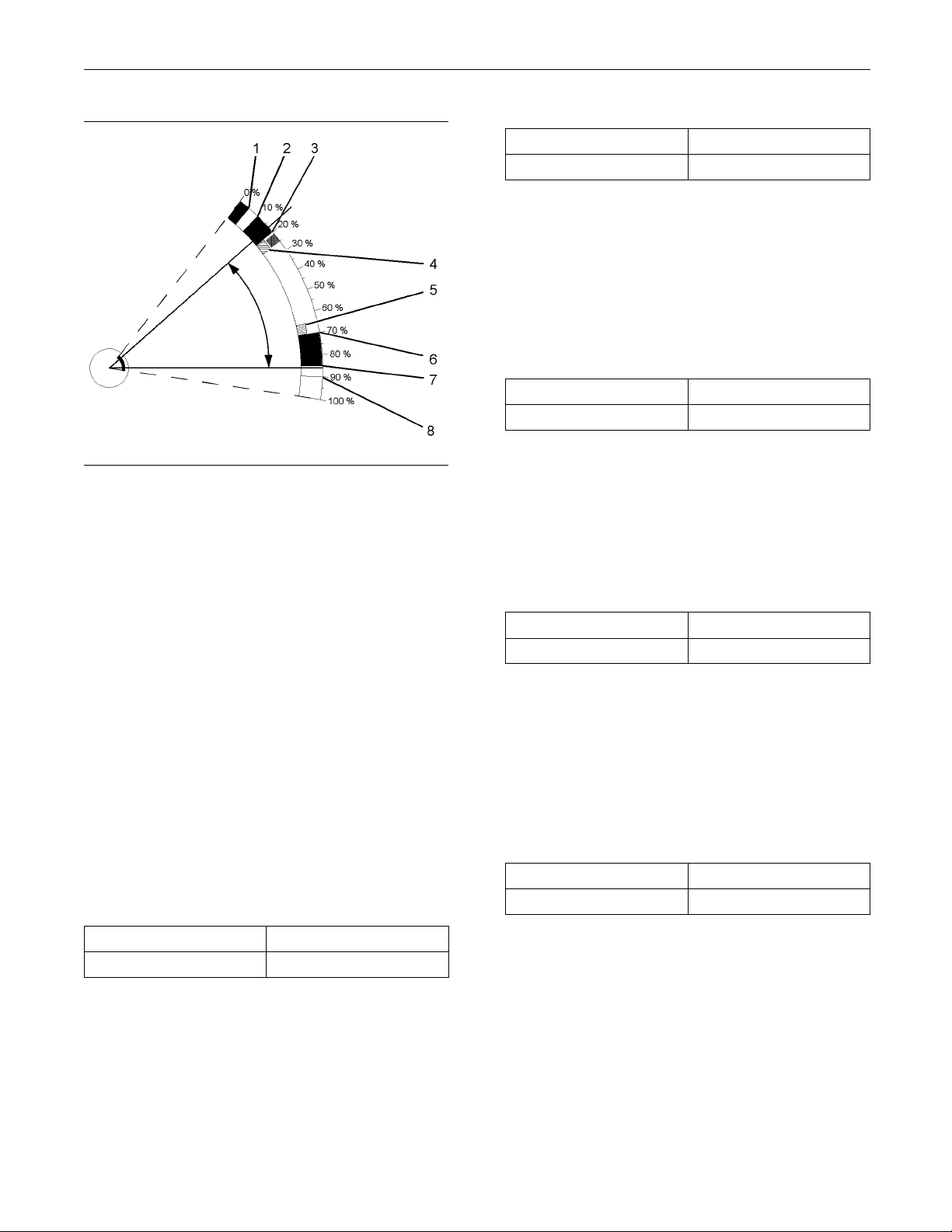
This document is printed from SPI². Not for RESALE
KENR6201-01 29
Troubleshooting Section
Table 9
Range
0 to 100 percent 0 percent
Default
Lower Position Limit
This is the minimum throttle percentage that will
be interpreted by the ECM as zero throttle. This
parameter is used with the value of initial lower
position limit to make an allowance for manufacturing
tolerances between different speed demand input
devices.
Table 10
Range
0 to 100 percent 0 percent
Default
Illustration 13
Typical Range of Throttle
(1) Lower Diagnostic Limit (Default=5)
(2) Lower Position Limit (Default=10)
(3) Initial Low er Position (Default=20)
(4) Lower Dead Z one % (Default=5)
(5) Upper Dead Z one % (Default=5)
(6) Initial Up per Position (Default=70)
(7) Upper Position Limit (Default=85)
(8) Upper Diagnostic Limit (Default=90)
g01224526
PWM inputs and communications port inputs do not
require any additional programming. If an analog
input is selected, the following parameters must be
programmed into the ECM.
Lower Diagnostic Limit
This is the minimum throttle percentage that should
be detected by the ECM in normal operation when
the pedal is in the “off” position. A value below this
limit will generate a short circuit diagnostic code.
The range of this diagnostic detection area is from
0 percent to the programmed value for the lower
position limit.
Table 8
Range Default
0 to 100 percent 0 percent
Upper Diagnostic Limit
This is the minimum throttle percentage that is
detected by the ECM in normal operation when the
pedal is in the maximum position. A value above this
limit will generate an open circuit diagnostic code.
The range of this diagnostic detection area is from
the programmed value of the upper position limit to
100 percent.
Upper Position Limit
This is the maximum throttle percentage that will be
interpreted by the ECM as full throttle. This parameter
is used with the value of the initial upper position limit
to make an allowance for manufacturing tolerances
between different speed demand input devices.
Table 11
Range Default
0 to 100 percent 0 percent
Initial Lower Position Li mit
This is the maximum throttle percentage that will
be interpreted by the ECM as zero throttle. This
parameter is used with the value of the lower
position limit to make an allowance for manufacturing
tolerances between different speed demand input
devices.
Table 12
Range Default
0to1
00 percent
0 per
cent
Initial Upper Position Limit
s is the minimum throttle percentage that will
Thi
be interpreted by the ECM as zero throttle. This
parameter is used with the value of the upper
sition limit to make an allowance for manufacturing
po
tolerances between different speed demand input
devices.
Page 30

This document is printed from SPI². Not for RESALE
30 KENR6201-01
Troubleshooting Section
Table 13
Range
0 to 100 percent 0 percent
Default
Lower Dead Zone
This is a throttle range above the initial lower position
limit before the engine will increase in rpm.
Table 14
Range Default
0 to 100 percent 0 percent
Upper Dead Zone
This is a throttle range that is below the initial upper
position limit that does not allow the engine speed
to increase.
Table 15
Range Default
0 to 100 percent 0 percent
Page 31

This document is printed from SPI². Not for RESALE
KENR6201-01 31
Troubleshooting Section
Customer Specified
Parameters
i03807232
Customer Specified
Parameters
Customer specified parameters allow the engine to
be configured to the exact needs of the application.
Customer parameters may be changed repeatedly as
operational requirements change.
The following information is a brief description of
the customer specified parameters. The following
parameter values are included with the descriptions:
Minimum
•
Maximum
•
Default
•
Table 17
Value
17 digits
The available characters
are dependent on the
service tool that is
being used.
Default
Not programmed
Throttle Lock Parameters
Throttle Lock Feature Installation Status
The “Throttle Lock Feature Installation Status” is
used to turn on the throttle lock features. When
this parameter is changed to “Installed”, the “PTO
engine Speed Setting”, the “Throttle Lock Increment
Speed Ramp Rate” and the “Throttle Lock Engine
Set Speed Increment” parameters are active and the
parameters can be programmed.
Table 18
Value Default
Not Installed
Installed
Not Installed
Engine Rating Parameter
Rating Number
The rating number is the selected rating within a
power rating family. The personality module defines
the power rating family. The personality module
can contain one to four ratings. The rating number
defines the power rating that is used within the power
rating family.
Table 16
Minimum Maximum
141
Default
ECM Identification Parameter
Equipment ID
“Equipment ID” is the identification of the equipment
that is assigned by the customer. The “Equipment
ID” is only for reference only by the customer. The
“Equipment ID” is not required by the Electronic
Control Module (ECM).
Throttle Lock Increment Speed Ramp
Rate
The “Throttle Lock Increment Speed Ramp Rate”
is the rate of engine acceleration when the PTO
switch is held in the ACCELERATE position. If this
parameter is set to “0”, the feature is turned off.
Table 19
Minimum Maximum Default
0 rpm/sec 600 rpm/sec 400 rpm/sec
Throttle Lock Engine Set Speed
Increment
The “Throttle Lock Engine Set Speed Increment”
controls the increase in engine speed when the
witch is briefly operated to ACCELERATE or
PTO s
DECELERATE. If this parameter is set to “0”, the
feature is turned off.
le 20
Tab
Minimum Maximum Default
0 rpm 200 rpm 10 rpm
Page 32

This document is printed from SPI². Not for RESALE
32 KENR6201-01
Troubleshooting Section
Miscellaneous
Monitoring Mode Shutdowns
“Monitoring Mode Shutdowns” controls the shutdown
feature that is associated with the engine monitoring
feature. When
code with a “-3” suffix is detected, the engine will be
shut down.
Table 21
this feature is enabled and an event
Value Default
Disabled
Enabled
Disabled
J1939 Continuous Fault Handling
Remote Torque Speed Control Enable
Status
The “Remote Torque Speed Control Enable Status”
parameter determines the way that faults will be
handled by the ECM when the “J1939 Torque Speed
Control (TSC1)” message is used as a speed request
input to the ECM. Programming the “Remote Torque
Speed Control Enable Status” to “Enabled” will cause
theECMtodisplayafaultcodeifavalidTSC1
message is not received by the engine ECM within
30 seconds of the engine starting. If the“ Remote
Torque Speed Control Enable Status” is programmed
to “Disabled”, the engine will display a 247-12 Data
Link malfunction immediately after a loss of a TSC1
message. Program “Remote Torque Speed Control
Enable Status” to “Enabled” if the ECM will always be
receivingaTSC1message.
Table 22
Value
Disabled
Enabled
Default
Disabled
Configurable Inputs
Overspeed Protection
The “Overspeed Protection” speed is the engine rpm
when a shutdown will occur. Overspeed protection
is used in order to protect the engine from damage.
Overspeedprotectionmustbeenabledin“Monitoring
Mode Shudowns”.
Table 23
Minimum Maximum
1500 rpm 2100 rpm 2100 rpm
Default
Configurable Governor Droop
“Configurable Governor Droop” allows the engine to
run in “droop mode” when the genset is operated in
parallel with
Table 24
Minimum Maximum Default
0 percent 8 percent 0 percent
other gensets.
Coolant Level Sensor
A coolant level sensor is an optional switch input.
Programming the “Coolant Level Sensor” parameter
to “Enabled” notifies the ECM that a coolant level
sensor input is present on pin J1:38. If this parameter
is programmed to “Enabled” and the coolant level
falls below the measured level, a “E2143-3” event
code will be displayed.
Table 25
Value Default
Disabled
Enabled
Disabled
Air Filter Restriction Switch Installation
Status
An “Air Filter Restriction Switch” is an optional
switch input. Programming the “Air Filter Restriction
Switch Installation Status” parameter to “Enabled”
notifies the ECM that an input from the air filter
restriction switch is present on pin J1:47. When this
parameter is programmed to “Enabled” and the air
filter restriction switch closes, an E172-1 or J107-15
event code will be displayed.
Table 26
Value
Disabled
Enabled
Default
Disabled
Fuel/Water Separator Switch Installation
Status
A fuel/water separator switch is an optional switch
input. Programming the “Fuel/Water Separator
Switch Installation Status” parameter to “Enabled”
notifies the ECM that a fuel/water separator switch
input is present on pin J1:44. When this parameter
is programmed to “Enabled” and the fuel/water
separator switch closes, an E232-1 or J97-15 event
code will be displayed.
Page 33

This document is printed from SPI². Not for RESALE
KENR6201-01 33
Troubleshooting Section
Table 27
Value
Disabled
Enabled
Default
Disabled
User Defined Switch Installation Status
Auserdefined shutdown switch is an optional
switch input. Programming the “User Defined Switch
Installation Status” parameter to “Enabled” notifies
theECMthatauserdefined switch input is present
on pin J1:48. If this parameter is programmed to
“Enabled” and the user defined shutdown switch
closes, the engine will shut down.
Table 28
Value Default
Disabled
Enabled
Disabled
Page 34

This document is printed from SPI². Not for RESALE
34 KENR6201-01
Troubleshooting Section
i02444244
Customer Specified
Parameters Table
Table 29
Customer Specified Parameters
ECM Parameter
Engine Rating Parameter
“Rating Number”
ECM Identification Parameter
“Equipment ID” 17 Digits
Throttle
“Throttle Lock Feature Installation
Status”
“Throttle Lock Increment Speed Ramp
Rate”
“Throttle Lock Engine Set Speed
Increment”
Miscellaneous
“Monitoring Mode Shutdowns”
J1939 Continuous Fault Handling
“Remote Torque Speed Control Enable
Status”
Configurable Inputs
“Overspeed Protection” 1500 to 2100 rpm 2100 rpm
“C
“Coolant Level Sensor”
“Air Filter Restriction Switch Installation
Status”
“Fuel/Water Separator Switch
Installation Status”
“User Defined Switch Installation Status”
Lock Parameters
onfigurable Governor Droop”
Available characters are dependent on
Possible Values
1to4 1
the service tool that is used
Installed
Not Installed
0 to 600 rpm/sec 400 rpm/sec
0 to 200 rpm 10 rpm
Disabled
Enabled
Disabled
led
Enab
to 8%
0%
Not Installed
Installed J1:38
ot Installed
N
Installed J1:47
Not Installed
Installed J1:44
Not Installed
Installed J1:48
Default Value
Not Progra
Not Installed
Not Installed
N
Not Installed
Not Installed
mmed
Disabled
Disabled
0%
ot Installed
Page 35

This document is printed from SPI². Not for RESALE
KENR6201-01 35
Troubleshooting Section
i02444245
Customer Specified
Parameters Worksheet
Table 30
Customer Specified Parameters Worksheet
Engine Rating Parameter
“Rating Numbers”
ECM Identifications Parameters
“Equipment ID”
ock Parameters
Miscellaneous
“Throttle Lock Feature Installation Status”
“Throttle Lock Increment Speed Ramp Rate”
“Throttle Lock Engine Set Speed Increment”
“Monitoring Mode Shutdowns”
J1939 Continuous Fault Handling
“Remote Torque Speed Control Enable Status”
rspeed Protection”
“Ove
“Configurable Governor Droop”
“Coolant Level Sensor”
“Air Filter Restriction Switch Installation Status”
“Fuel/Water Separator Switch Installation Status”
“User Defined Switch Installation Status”
Throttle L
Configurable Inputs
Page 36

This document is printed from SPI². Not for RESALE
36 KENR6201-01
Troubleshooting Section
System Configuration
Parameters
i03818369
System Configuration
Parameters
System configuration parameters affect the emissions
of the engine or the power of the engine. System
configuration parameters are programmed at the
factory. Normally, system configuration parameters
would never need to be changed through the life of
the engine. System configuration parameters must be
reprogrammed if an Electronic Control Module (ECM)
is replaced. System configuration parameters do not
need to be reprogrammed if the ECM software is
changed. Factory passwords are required to change
these parameters. The following information is a
description of the system configuration parameters.
Full Load Setting
The full load setting is a number that represents
the adjustment to the fuel system that was made at
the factory in order to fine tune the fuel system. If
the ECM is replaced, the full load setting must be
reprogrammed in order to prevent a 268-2 diagnostic
code from becoming active.
This code does not need to be programmed when
the replacemen
If the ECM is for a different engine rating, then the
following com
pistons, fuel injectors, and other components.
The engine information ratings plate must also be
changed in or
Some systems such as the cooling system or the
transmissi
engine is rerated. Contact the application OEM for
further information.
t ECM is for the same engine rating.
ponents may need to be changed:
der to reflect the new rating.
on may also require changes when the
Engine Serial Number
When a new ECM is delivered, the engine serial
number in the ECM is not programmed. The engine
serial num
engine serial number that is stamped on the engine
information plate.
ber should be programmed to match the
ECM Software Release Date
This parameter is defined by the rating interlock
and this parameter is not programmable. The ECM
softwar
of the software. The Customer parameters and the
software change levels can be monitored by this
date. Th
(DEC08). DEC is the month (December). 08 is the
year (2008).
e release date is used to provide the version
edateisprovidedinthemonthandtheyear
Full Torque Setting
Full torque setting is similar to full load setting. If
the ECM is replaced, the full torque setting must be
reprogrammed in order to prevent a 268-2 diagnostic
code from becoming active.
Rating Interlock
The rating interlock is a code that prevents the use of
an incorrect power rating and/or emission rating for
aspecific engine. Each horsepower rating and each
emission certification has a different code to all other
horsepower ratings and emission certifications.
When an ECM is replaced, this rating interlock code
must match the code that is stored in the ECM. If the
rating interlock code does not match the code that is
stored in the ECM, both of the following situations
will exist:
The engine will not run.
•
Diagnostic code 253-2 (Personality Module erratic,
•
intermittent or incorrect) will be active.
Note: The flash programming of a new rating
interlock replaces the old rating interlock.
Page 37

This document is printed from SPI². Not for RESALE
KENR6201-01 37
Troubleshooting Section
Troubleshooti
ng without a
Diagnostic Code
i03858309
Alternator Noise
Note: This is not an electronic system fault.
Refer to Systems Operation, Testing and Adjusting
for information on possible electrical causes of this
condition.
Probable Causes
Alternator drive belt
•
Alternator mounting bracket
•
Alternator drive pulley
•
Alternator bearings
•
Alternator Bearings
Check for excessive play of the shaft in the alternator.
Check for wear in the alternator bearings. The
alternator is
must be replaced if the bearings are worn. Refer to
Disassembly and Assembly, “Alternator - Remove”
and Disassem
a nonserviceable item. The alternator
bly and Assembly , “Alternator - Install”.
i03436581
Alternator Will Not Charge
Note: This is not an electronic system fault.
Probable Causes
Alternator drive belt
•
Automatic tensioner
•
Charging circuit
•
Alternator
•
Recommended Actions
Alternator Drive Belt
Inspect the condition of the alternator drive belt. If the
alternator drive belt is worn or damaged, check that
the drive belt and the pulley are correctly aligned. If
the alignment is incorrect, investigate the cause of
the misalignment. If the alignment is correct, replace
the drive belt. Refer to Disassembly and Assembly,
“Alternator Belt - Remove and Install”.
Alternator Mounting Bracket
Inspect the alternator mounting bracket for cracks
and wear. Repair the mounting bracket or replace
the mounting bracket in order to ensure that the
alternator drive belt and the alternator drive pulley
are in alignment.
Alternator Drive Pulley
Remove the nut for the alternator drive pulley and
then inspect the nut and the drive shaft. If no damage
is found, install the nut and tighten the nut to the
correct torque. Refer to Specifications, “Alternator
and Regulator” for the correct torque.
Recommended Actions
Alternator Drive Belt
Inspect the condition of the alternator drive belt. If
the alternator drive belt is worn or damaged, check
that the drive belt for the alternator and the pulley
are correctly aligned. If the alignment is incorrect,
investigate the cause of the misalignment. If the
alignment is correct, replace the drive belt. Refer
to Disassembly and Assembly, “Alternator Belt Remove and Install”.
Automatic Tensioner
Check the tension on the alternator drive belt. If
necessary, replace the automatic tensioner. Refer to
Disassembly and Assembly, “Alternator - Remove”
and Disassembly and Assembly, “Alternator - Install”.
Charging Circuit
Inspect the battery cables, wiring, and connections in
the charging circuit. Clean all connections and tighten
all connections. Replace any faulty parts.
Page 38

This document is printed from SPI². Not for RESALE
38 KENR6201-01
Troubleshooting Section
Alternator
Verify that the alternator is operating correctly.
Refer to Systems Operation, Testing and Adjusting,
“Alternator item. If the alternator is not operating correctly, the
alternator must be replaced. Refer to Disassembly
and Assembly
Disassembly and Assembly , “Alternator - Install”.
Test”. The alternator is not a serviceable
, “Alternator - Remove” and
i03807312
Battery
Note: This is not an electronic system fault.
Probable Causes
Charging circuit
•
Battery
•
Auxiliary device
•
Can Not Reach Top Engin e
RPM
Note: If this
Troubleshooting, “Low Power”.
Probable Causes
Diagnostic
•
ECM parameters
•
Signal for the Speed demand input
•
Air intake
•
Val ve la sh
•
Turbocharger
•
Fuel supp
•
fault occurs only under load, refer to
codes
and exhaust system
ly
i03807352
Recommended Actions
Charging Circuit
If a fault in the battery charging circuit is suspected,
refer to Troubleshooting, “Alternator Will Not Charge”.
Faulty Batte ry
1. Check that the battery is able to maintain a
charge. Refer to Systems Operation, Testing and
Adjusting, “Battery - Test”.
2. If the battery does not maintain a charge,
replace the battery. Refer to the Operation and
Maintenance Manual, “Battery - Replace”.
Auxiliary Device
1. Check that an auxiliary device has drained the
battery by being left in the ON position.
2. Charge the battery.
3. Verify that the battery is able to maintain a charge
when all auxiliary devices are switched off.
Low compression (cylinder pressure)
•
Individual malfunctioning cylinders
•
Electro
•
Recomm
nic unit injectors
ended Actions
Diagnostic Codes
Check for active diagnostic codes on the electronic
service tool. Troubleshoot any active codes before
nuing with this procedure.
conti
ECM Parameters
1. Ensure that the fault is not an incorrectly
programmed parameter.
2. Ensure that the correct mode was selected by
using the electronic service tool.
3. Use the electronic service tool to verify the correct
engine rating for the engine.
4. Use the electronic service tool to verify the
maximum engine speed limit.
5. Use the electronic service tool to reset the
parameters to the OEM specifications.
6. Ensure that the repairs have eliminated the poor
performance.
Page 39

This document is printed from SPI². Not for RESALE
KENR6201-01 39
Troubleshooting Section
7. If the repairs have not eliminated the faults
proceed to “Thr
Input”.
Signal f or the
1. Use the electronic service tool and observe the
signal for th
2. If the signal is erratic, refer to Troubleshooting,
“Speed Cont
Troubleshooting, “Speed Control (Digital) - Test”.
3. If the fault
“Air Intake and Exhaust System”.
Air Intake
1. Check the air filter restriction indicator, if equipped.
2. Ensure that the air filter is clean and serviceable.
3. Check the
the following defects:
Blockag
•
ottle Signal for the Speed Demand
Speed Demand Input
e speed demand input.
rol (Analog) - Test” or refer to
has not been eliminated, proceed to
and Exhaust System
air intake and the exhaust system for
es
3. Check that the compressor housing for the
turbocharger i
4. Check that the turbine housing for the turbocharger
is free of dirt
5. Check that the turbine blades rotate freely in the
turbocharge
6. Ensure that the wastegate on the turbocharger is
adjusted co
Testing and Adjusting, “Turbocharger - Inspect”.
If the wastegate actuator is faulty, replace the
wastegate a
Assembly, “Turbocharger - Disassemble” and
Disassembly and Assembly, “Turbocharger Assemble”
7. If necessary, replace the turbocharger. Refer
to Disasse
- Remove” and Disassembly and Assembly,
“Turbocharger - Install”.
8. Check that the repairs have eliminated the faults.
9. If the rep
to “Fuel Supply”.
s free of dirt, debris and damage.
, debris and damage.
r.
rrectly. Refer to Systems Operation,
ctuator. Refer to Disassembly and
.
mbly and Assembly, “Turbocharger
airs have not eliminated the fault proceed
Restrictions
•
Damage to the air intake and exhaust lines and
•
hoses
4. Make all necessary repairs to the engine.
5. Ensure
6. If the fault has not been eliminated, proceed to
“Valv
that the repairs have eliminated the fault.
e Lash”.
Valve Lash
1. Check the valve lash and reset the valve lash, if
necessary. Refer to Systems Operation, Testing
djusting, “Engine Valve Lash - Inspect and
and A
Adjust”.
e repair does not eliminate the fault proceed
2. If th
to “Turbocharger”.
bocharger
Tur
Note: The turbocharger that is installed on this
ine is a nonserviceable item. If any mechanical
eng
fault exists, except for the wastegate actuator, then
the turbocharger must be replaced. The wastegate
tuator can be replaced.
ac
1. Ensure that the mounting bolts for the turbocharger
e tight.
ar
2. Check that the oil drain for the turbocharger is not
locked or restricted.
b
Fuel Sup
1. Visually check the fuel tank for fuel. The fuel
gauge m
2. Ensure that the fuel supply valve is in the full
OPEN po
3. If the temperature is below 0 °C (32 °F), check
for so
4. Visually inspect the fuel supply lines for
restr
5. Check that the low pressure fuel lines are tight
and s
6. Remove the fuel filters. Inspect the fuel filters for
cont
Operation and Maintenance Manual, “Fuel System
Filter- Replace and Fuel System Primary Filter
(Wa
the cause of the contamination.
7. Che
Systems Operation, Testing and Adjusting, “Fuel
Quality - Test”.
8. Check for air in the low pressure fuel system. Refer
to Systems Operation, Testing and Adjusting, “Air
in
9. Ensure that the fuel system has been primed.
efer to Systems Operation, Testing and
R
Adjusting, “Fuel System - Prime”.
ply
ay be faulty.
sition.
lidified fuel (wax).
ictions.
ecured properly.
amination. Install new fuel filters. Refer to the
ter Separator) Element - Replace”. Determine
ck the diesel fuel for contamination. Refer to
Fuel - Test”.
Page 40

This document is printed from SPI². Not for RESALE
40 KENR6201-01
Troubleshooting Section
10. Check the fuel pressure. Refer to Systems
Operation, Tes
Pressure - Test”.
Contact with high pressure fuel may cause fluid
penetration and burn hazards. High pressure fuel spray may
low these inspection, maintenance and service instructions may cause personal injury or death.
Contact with high pressure fuel may cause personal
injury or death. Wait 60 seconds after the engine has
stopped to allow fuel pressure to purge before any
service or repair is performed on the engine fuel lines.
11. If the high pressure fuel lines have a leak, the
high pressure fuel lines must be replaced. Refer to
Disassembly and Assembly, “Fuel injection lines Remove and Fuel injection lines - Install”.
12. If the repairs do not eliminate the fault, proceed to
“Low Compression (Cylinder P ressure)”.
ting and Adjusting, “Fuel System
cause a fire hazard. Failure to fol-
NOTICE
Low Compression (Cylinder Pressure)
1. Perform a compression test. Refer to Systems
Operation, Testing and Adjusting, “Compression
-Test”.
2. If low compression is noted on any cylinders,
investigate the cause and rectify the cause.
Individual M alfunctioning Cylinders
1. With the engine speed at a fast idle, use the
electronic service tool to isolate one cylinder at
a time. Note if
speed. If a reduction in engine speed is not noted,
the isolated cylinder is not operating under normal
conditions.
results in a reduction of engine speed that is less
than normal, this may indicate that the cylinder is
operating b
the cause of the fault on any cylinder that is
not operating. Investigate the cause of the fault
on any cylin
performance.
2. If all cyli
faults were detected proceed to “Electronic Unit
Injectors”.
there is any reduction in engine
If the isolation of a particular cylinder
elow normal performance. Investigate
der that is operating below normal
nders have been checked and no
Electronic Unit Injectors
1. With the e
electronic service tool to isolate one cylinder at
a time. Note if there is any reduction in engine
speed. I
the isolated electronic unit injector is not operating
under normal conditions. If the isolation of a
particu
speed that is less than normal, this may indicate
that the electronic unit injector is operating below
normal
2. Remove the electronic unit injector from the
suspec
Assembly, “Electronic Unit Injector - Remove”.
ngine speed at a fast idle, use the
f a reduction in engine speed is not noted,
lar cylinder results in a reduction of engine
performance.
t cylinder. Refer to Disassembly and
Possible causes of low compression are shown
in the following list:
Loose glow plugs
•
Faulty piston
•
Faulty piston rings
•
Worn cylinder bores
•
Worn valves
•
Faulty cylinder head gasket
•
Damaged cylinder head
•
3. Perform all necessary repairs.
4. Ensure that the repairs have eliminated the faults.
5. If the repair does not eliminate the fault refer to
“Individual Malfunctioning Cylinders”.
3. Insta
4. Repeat the test in 1. If the fault is still apparent,
ll a new electronic unit injector. Refer to
Disassembly and Assembly, “Electronic Unit
Injector - Install”.
remove the replacement electronic unit injector
nstall the original electronic unit injector.
and i
Refer to Disassembly and Assembly, “Electronic
Unit Injector - R emove” and Disassembly and
mbly, “Electronic Unit Injector - Install”.
Asse
i03807529
Coolant in Engine Oil
Note: This is not an electronic system fault.
Probable Causes
Engine oil cooler
•
Cylinder head gasket
•
Page 41

This document is printed from SPI². Not for RESALE
KENR6201-01 41
Troubleshooting Section
Cylinder head
•
Cylinder block
•
Recommended Actions
Engine Oil Coo
1. Drain the engine lubricating oil from the engine.
2. Check for leaks in the oil cooler assembly. Refer
to Systems Operation, Testing and Adjusting,
“Cooling Sy
leak is found, install a new oil cooler. Refer to
Disassembly and Assembly, “Engine Oil Cooler
- Remove” a
“Engine Oil Cooler - Install” for the correct
procedure.
Cylinder Head Gasket
1. Remove th
and Assembly, “Cylinder Head - Remove” for the
correct procedure.
2. Inspect the cylinder head gasket for faults and any
signs of leakage.
3. To fit a new cylinder head gasket, refer to
Disassembly and Assembly, “Cylinder Head -
” for the correct procedure.
Install
ler
stem” for the correct procedure. If a
nd Disassembly and Assembly,
e cylinder head. Refer to Disassembly
Cylinder Block
Inspect the top face of the cylinder block for faults
and signs of leakage. If a fault is found, replace
the cylinder b
determine the cause of the leakage. Refer to Systems
Operation, Testing and Adjusting, “Cylinder Block Inspect” for
lock. If signs of leakage are found,
the correct procedure.
Assembly after Repair
1. Install the cylinder head. Refer to Disassembly
and Assembly, “Cylinder Head - Install”.
2. Remove the oil filter element. Install a new engine
oil filter element. Fill the engine with clean engine
oil to the c
and Maintenance Manual, “Engine Oil and Filter
- Change” for more information.
orrect level. Refer to the Operation
i03438642
Coolant Tem perature Is Too
High
Note: This is not an electronic system fault.
Probable Causes
4. If there was no obvious signs of a faulty head
gasket
proceed to “Cylinder Head”.
Cylinder Head
1. Check the cylinder head for flatness. Refer
to Systems Operation, Testing and Adjusting,
nder Head - Inspect” for the correct procedure.
“Cyli
2. Check the mating face of the cylinder head
aults and signs of leakage. If a fault is
for f
found, replace the cylinder head. If signs of
leakage are found, determine the cause of the
age. Refer to Systems Operation, Testing and
leak
Adjusting, “Cylinder Head - Inspect” for the correct
procedure.
3. Check the internal core plugs in the cylinder head
for signs of leakage.
4. If the cylinder head is flat and if the cylinder head
does not have any faults, refer to “Cylinder Block”.
Radiator fins
•
Coolant level
•
Radiator cap and/or pressure relief valve
•
Coolant temperature gauge
•
Restriction in the coolant system
•
Water temperature regulator
•
Engine cooling fan
•
Coolant pump
•
Cylinder head gasket
•
Recommended Actions
Radiator Fins
Check the radiator fins for dirt, debris, and/or damage.
Remove any dirt and/or debris and straighten any
bent fins.
Page 42

This document is printed from SPI². Not for RESALE
42 KENR6201-01
Troubleshooting Section
Coolant Level
1. Inspect the coolant level. If necessary, add
coolant.
2. Check the cooling system for leaks. Repair any
leaks immediately.
Radiator Cap and/or Pressure Relief
Valve
1. Pressure test the cooling system. Refer to
Systems Operation, Testing and Adjusting,
“Cooling Sy
2. Check that the seating surfaces of the pressure
relief val
undamaged.
3. Check oper
and/or the radiator cap. If necessary, clean the
components and/or replace the components.
stem” for the correct procedure.
ve and the radiator cap are clean and
ation of the pressure relief valve
Coolant Temperature Gauge
Compare
from the electronic service tool to the reading for the
coolant temperature from a calibrated test gauge.
the reading for the coolant temperature
Restriction in t he Coolant System
1. Visual
ly inspect the cooling system for collapsed
hoses and/or other restrictions.
3. Check the engine cooling fan for damage. If
necessary, rep
and Assembly, “Fan - Remove and Install”.
lace the fan. Refer to Disassembly
Coolant Pump
1. Inspect the impeller of the coolant pump for
damage and/o
2. Make sure that the drive gear is not loose on the
drive shaft
3. If necessary, replace the coolant pump. Refer
to Disassem
Remove” and Disassembly and Assembly, “Water
Pump - Install”.
rerosion.
of the coolant pump.
bly and Assembly, “Water Pump -
Cylinder Head Gasket
Switch off
to below normal working temperature. Remove
the pressure cap for the coolant system. Start the
engine an
of bubbles. If bubbles are present in the coolant,
combustion gases may be entering the cooling
system.
recommended action for the cylinder head gasket
within Troubleshooting, “Coolant in Engine Oil”.
Check th
recommended action for checking flatness of the
cylinder head within Systems Operation, Testing and
Adjust
cap if there are no bubbles in the coolant.
theengineandallowtheenginetocool
d inspect the coolant for the presence
Check the cylinder head gasket. Refer to the
e cylinder head for flatness. Refer to the
ing, “Cylinder Head - Inspect”. Fit the pressure
2. Clean t
to Systems Operation, Testing and Adjusting,
“Cooling System”.
he radiator and flush the radiator. Refer
Water Temperature Regulator
Check
operation. Refer to Systems Operation, Testing and
Adjusting, “Cooling System” for the proper procedure.
If ne
Refer to Disassembly and Assembly, “Water
Temperature Regulator - Remove and Install” for
more
the water temperature regulator for correct
cessary, replace the water temperature regulator.
information.
Engine Cooling Fan
1. Make sure that the engine cooling fan is correctly
installed.
2. Make sure that the engine cooling fan is being
driven correctly by the drive belt. If necessary,
ghten the drive belt or replace the drive belt.
ti
Refer to Disassembly and Assembly, “Alternator
Belt - Remove and Install”.
i03807570
ECM Wi
llNotAcceptFactory
Passwords
Prob
One of the following items may not be recorded
cor
•
•
•
•
Recommended Actions
1. Verify that the correct passwords were entered.
able Causes
rectly on the electronic service tool:
Passwords
Serial numbers
tal tattletale
To
Reason code
Check every character in each password. Remove
he electrical power from the engine for 30
t
seconds and then retry.
Page 43

This document is printed from SPI². Not for RESALE
KENR6201-01 43
Troubleshooting Section
2. Verify that the electronic service tool is displaying
the “Factory Pa
3. Use the electronic service tool to verify that the
following inf
Engine serial number
•
Serial number for the electronic control module
•
Serial numb
•
Total tattletale
•
Reason code
•
ssword” screen.
ormation has been entered correctly:
er for the electronic service tool
i03438660
ECM Will Not Communicate
with Other S yste ms or Display
Modules
Probable Causes
Electrical connectors
•
Electro
•
Recomm
nic Control Module (ECM)
ended Actions
i03807610
Electronic Service Tool Will
Not Communicate with ECM
Probable Causes
Configuratio
•
Electrical connectors
•
Communication adapter and/or cables
•
Electrica
•
Electronic service tool and related hardware
•
Electrical power supply to the Electronic Control
•
Module (ECM)
Data link
•
Recommended Actions
Start th
will not communicate with the electronic service tool,
continue with this procedure. If the engine will not
start, r
Will Not Start”. If the engine will not crank, refer to
Troubleshooting, “Engine Will Not Crank”.
e engine. If the engine starts, but the ECM
efer to Troubleshooting, “Engine Cranks but
n for the communications adapter
l power supply to the diagnostic connector
1. Connect the electronic service tool to the
stic connector. If the ECM does not
diagno
communicate with the electronic service tool, refer
to Troubleshooting, “Electronic Service Tool Will
Not Co
2. Ensure that the following items are
corre
to Troubleshooting, “Electrical Connectors Inspect”.
•
•
•
3. Troubleshoot the Perkins Data Link for possible
faults. Refer to Troubleshooting, “Data Link Circuit
-Te
mmunicate with ECM”.
ctly installed and undamaged. Refer
P1/J1 and P2/J2 connectors on the ECM
ng to display modules
Wiri
Wiring to other control modules
st”.
Configuration for the Communications
Adapter
1. Access “Preferences” under the “Utilities” menu
on the electronic service tool.
2. Verify that the correct “Communications Interface
Device” is selected.
3. Verify that the correct port is selected for use by
the communication adapter.
Note: The most commonly used port is “COM 1”.
4. Che
ck for any hardware that is utilizing the
same port as the communications adapter. If any
devices are configuredtousethesameport,exit
lose the software programs for that device.
or c
Electrical Connectors
Check for correct installation of the P1/J1 and P2/J2
ECM connectors and of the diagnostic connector.
fer to Troubleshooting, “Electrical Connectors -
Re
Inspect”.
Page 44

This document is printed from SPI². Not for RESALE
44 KENR6201-01
Troubleshooting Section
Communication Adapter and/or Cables
1. Make sure that the firmware and driver files are
the most current files that are available for the
type of commun
If the firmware and driver files do not match, the
communication adapter will not communicate with
the electron
2. Disconnect the communication adapter and the
cables from
the communication adapter to the diagnostic
connector.
3. Verify that the correct cable is being used between
the communication adapter and the diagnostic
connector
Service Tools”.
4. If the lapt
operating system, restart the laptop computer in
order to eliminate the possibility of a conflict in
the softw
are.
ication adapter that is being used.
ic service tool.
the diagnostic connector. Reconnect
. Refer to Troubleshooting, “Electronic
op computer is using a Windows
Electrical Power Supply to the Diagnostic
Connect
or
Engine Cranks but Will Not
Start
Probable Causes
Diagnostic c
•
Visible faults
•
Air intake and exhaust system
•
Primary sp
•
Low pressure fuel system
•
Secondary speed/timing sensor
•
High pres
•
Glow plugs
•
Val ve la sh
•
odes
eed/timing sensor
sure fuel system
i03807671
Verify that battery vol tage is present between
termina
communication adapter is not receiving power, the
LED display on the communication adapter will not
be illu
ls A and B of the diagnostic connector. If the
minated.
Electronic Service Tool and Related
Hardwa
In order to eliminate the electronic service tool and
the re
connect the electronic service tool to a different
engine. If the same fault occurs on a different engine,
check
hardware in order to determine the cause of the fault.
Elec
re
lated hardware as the cause of the fault,
the electronic service tool and the related
trical Power Supply to the Electronic
Control Module (ECM )
k power to the ECM. Refer to Systems
Chec
Operation, Testing and Adjusting, “Charging System
-Test”.
Note: If the ECM is not receiving battery voltage, the
ECM will not communicate.
Low comp
•
Recomme
Do not c
30 seconds. Allow the starting motor to cool for two
minutes before cranking the engine again.
ression (cylinder pressure)
nded Actions
NOTICE
rank the engine continuously for more than
Diagnostic Codes
ne of the following methods to check for active
Use o
diagnostic codes:
h Codes
Flas
•
The display on the control panel
•
The electronic service tool
•
sh Codes
Fla
Note: The following procedure is only applicable if
e machine is equipped with the appropriate warning
th
lamps.
Data Link
oubleshoot the data link for possible faults. Refer
Tr
to Troubleshooting, “Data Link Circuit - Test”.
eck the warning lamps on the control panel
1. Ch
for flash codes. Flash codes are explained in
Troubleshooting, “Indicator Lamps”.
2. If any flash codes are displayed, troubleshoot
the codes before continuing with this procedure.
efer to Troubleshooting, “Troubleshooting with a
R
Diagnostic Code”.
Page 45

This document is printed from SPI². Not for RESALE
KENR6201-01 45
Troubleshooting Section
3. Attempt to start the engine. If the engine will not
start, proceed
Display on the Control Panel
Note: The following procedure is only applicable if
the machine is equipped with a display on the control
panel.
1. Check the display on the control panel for active
diagnostic
2. Troubleshoot any active codes before continuing
with this pr
“Troubleshooting with a Diagnostic Code”.
3. Attempt to
start, proceed to “Visible Faults”.
Electroni
1. Connect the electronic service tool to the
2. Check for active diagnostic codes on the electronic
c Service Tool
diagnost
service t
to “Visible Faults”.
codes.
ocedure. Refer to Troubleshooting,
start the engine. If the engine will not
ic connector.
ool.
If the ambient temperature is below 0 °C (32 °F),
•
make sure that t
engine oil and oil for the machine is used.
Check that the
•
Use the electronic service tool to check the
•
average cran
cranking speed is less than 150 rpm, investigate
the cause of the fault.
Make sure that all fuel filters are correctly
•
installed.
Drain any water from the primary fuel filter/water
•
separator.
3. Rectify any faults that are found during the visual
checks.
4. Attempt to start the engine. If the engine will not
start, proceed to “Air Intake and Exhaust System”.
he correct specification of
battery voltage is correct.
king speed of the engine. If the
Air Intake and Exhaust System
1. Check th
eairfilter restriction indicator, if equipped.
3. Troubleshoot any active codes before proceeding
with thi
“Troubleshooting with a Diagnostic Code”.
4. Attempt
start, proceed to “Visible Faults”.
Visibl
1. Visually inspect the engine for the following faults:
•
•
•
•
•
2. Che
•
•
•
s procedure. Refer to Troubleshooting,
to start the engine. If the engine will not
eFaults
Missing components
Damag
Damaged electrical cables or loose electrical
cabl
Oil leaks
Fuel leaks
Check for smoke from the exhaust when the
eng
cranking, there may be a mechanical fault in the
engine. Refer to “Low C ompression (Cylinder
Pr
Check for the proper level of fuel, oil and
co
Ensure that the fuel supply valve (if equipped)
i
ed components
es
ck the following items:
ine is cranking. If smoke is seen during
essure)”.
olant.
s in the full OPEN position.
2. Ensure that the air filter is clean and serviceable.
3. Check the air intake and exhaust systems for the
following defects:
Blockages
•
ctions
Restri
•
Damage to lines or hoses
•
4. Repair any defects before attempting to restart
the engine.
5. Attempt to start the engine. If the engine will not
start, proceed to “Primary Speed/timing Sensor”.
Primary Speed/timing Sensor
1. Disc
2. Att
3. If the engine starts, check for a fault in the circuit
4. If the engine does not start, inspect the timing ring
5. If necessary, repair the timing ring. Refer to
onnect the P401 connector from the primary
speed/timing sensor.
empt to start the engine.
the primary speed/timing sensor. Refer to
for
Troubleshooting, “Engine Speed/Timing Sensor
Circuit - Test”.
on the crankshaft for misalignment.
Disassembly and Assembly, “Crankshaft Timing
ing - Remove and Install”.
R
Page 46

This document is printed from SPI². Not for RESALE
46 KENR6201-01
Troubleshooting Section
6. Attempt to start the engine. If the engine will not
start, proceed
to “Low Pressure Fuel System”.
Low Pressure Fuel System
1. If the temperature is below 0 °C (32 °F), check
for solidified fuel (wax).
2. Check for fuel supply lines that are restricted.
3. Check that t
installed.
4. Check the di
Systems Operation, Testing and Adjusting, “Fuel
Quality - Test”.
5. Check for air in the fuel system. Refer to Systems
Operation, Testing and Adjusting, “Air in Fuel Tes t ” .
6. Ensure that the fuel system has been primed.
Refer to S
Adjusting, “Fuel System - Prime”.
7. Attempt
start, continue with this procedure.
8. Replace
fuel filter. Refer to the Operation and Maintenance
Manual, “Fuel System Primary Filter (Water
Separa
9. Attempt to start the engine. If the engine will not
start,
10. Check the flow of fuel through the transfer pump.
If the
less than 250 mL per minute at 150 rpm, replace
the transfer pump. Refer to Disassembly and
Assem
Disassembly and Assembly, “Fuel Transfer Pump
-Install”.
11. Attempt to start the engine. If the engine will
not start, proceed to “Secondary Speed/timing
or”.
Sens
he low pressure fuel lines are correctly
esel fuel for contamination. Refer to
ystems Operation, Testing and
to start the engine. If the engine will not
the primary fuel filter and the secondary
tor) Element - Replace”.
continue with this procedure.
flow of fuel through the transfer pump is
bly, “Fuel Transfer Pump - Remove” and
b. If the signal from the secondary speed/timing
sensor is 0 rpm,
speed/timing sensor. Refer to Troubleshooting,
“Engine Speed/Timing Sensor Circuit - Test”.
c. If a fault is identified in the circuit for the
secondary speed/timing sensor, repair the fault
and then atte
engine will not start, proceed to “High Pressure
Fuel System”.
d. If the signal from the secondary speed/timing
sensor is greater than 0 rpm and the engine
will not sta
System”.
High Press
1. Use the electronic service tool to check the
absolute f
cranking at a minimum speed of 150 rpm.
2. If the abs
25 MPa (3625 psi), perform the following
procedure:
a. Check that the inlet pressure at the fuel rail
pump is greater than 50 kPa (7.25 psi). If the
inlet pr
repeat the diagnostic process from “Low
Pressure Fuel System”.
b. Check for fuel leaks in the high pressure
fuel system. Rectify any fuel leaks and then
rechec
rail pressure is greater than 25 M Pa (3625 psi),
proceed to test step 3.
c. Use the electronic service tool to perform a
solenoid test on the fuel rail pump. Refer to
Troub
Tes t ” .
d. If an
of Step 2.c, attempt to start the engine. If the
engine will not start, repeat the diagnostic
proc
ure Fuel System
uel rail pressure while the engine is
olute fuel rail pressure is less than
essure is less than 50 kPa (7.25 psi),
k the pressure in the fuel rail. If the fuel
leshooting, “Fuel Rail Pump Solenoid -
y service has been performed as a result
ess from “Diagnostic Codes”.
investigate the secondary
mpt to start the engine. If the
rt, proceed to “High Pressure Fuel
Secondary Speed/timing S ensor
1. Connect the electronic service tool to the
diagnostic connector.
2. Check that the desired fuel rail pressure is at least
25 MPa (3625 psi) when the engine is cranking.
3. If the desired fuel rail pressure is less than 25 MPa
(3625 psi), perform the following procedure:
a. Use the electronic service tool to check the
signal from the secondary speed/timing sensor
hile the engine is cranking.
w
e. Check the pressure relief valve in the fuel
l for leakage. If the pressure relief valve is
rai
leaking, replace the valve and recheck the
pressure in the fuel rail.
f. If the pressure relief valve in the fuel rail is
not leaking, check for fuel in the engine oil
stem. If fuel is suspected in the oil system,
sy
take an engine oil sample for analysis. Refer to
Operation and Maintenance Manual, “Engine
l Sample - Obtain”. If the analysis confirms
Oi
that there is fuel in the engine oil system,
investigate the cause.
Page 47

This document is printed from SPI². Not for RESALE
KENR6201-01 47
Troubleshooting Section
g. If fuel is not found in the oil system, check the
electronic uni
off.
h. If the leak off
in 30 seconds for a 6 cylinder engine or the
leak off is greater than 25 mL (0.85 oz) in 30
seconds for a
electronic unit injectors.
Note: The fa
replace the pump.
i. If the leak o
seconds for a 6 cylinder engine or the leak off
is less than 25 mL (0.85 oz) in 30 seconds for
a 4 cylinde
3. If the absolute fuel rail pressure is greater
than 25 MPa
procedure:
a. Use the el
that the status of the electronic unit injectors
is not “Disabled”. If the injectors are disabled
but the in
with the electronic service tool, proceed to test
step 3.d.
b. If the electronic unit injectors are not disabled,
use the electronic service tool to perform an
r solenoid test. Refer to Troubleshooting,
injecto
“Injector Solenoid Circuit - Test”.
c. If any s
of Step 3.b, attempt to start the engine. If the
engine will not start, proceed to “Glow Plugs”.
d. Make sure that the latest flash file for the
application is installed in the ECM. Refer to
leshooting, “Flash Programming”.
Troub
t injectors for excessive fuel leak
is greater than 38 mL (1.3 oz)
4 cylinder engine, replace the
ult is not in the fuel rail pump. Do not
ff is less than 38 mL (1.3 oz) in 30
r engine, proceed to Test Step 3.d.
(3625 psi), perform the following
ectronic service tool to make sure
jectors were not intentionally disabled
ervice has been performed as a result
i. If the engine starts normally, reconnect the
suspect ECM and
returns when the suspect ECM is installed.
j. If the engine w
ECM, replace the ECM. Check that the engine
starts normally. If the engine starts normally, no
further test
k. Replace the ECM again and then replace the
fuel rail pu
eliminated. If the engine will not start, proceed
to “Glow Plugs”.
l. Check the timing of the fuel rail pump. Refer
to Systems Operation, Testing and Adjusting,
“Fuel Inje
m. If the timing of the fuel rail pump required
adjustmen
proceed to “Glow Plugs”.
n. If the tim
replace the fuel rail pump. If the engine will not
start, proceed to “Glow Plugs”.
ing is required.
mp. Verify that the fault has been
ction Timing - Check”.
t and the engine will not start,
ing of the fuel rail pump was correct,
then verify that the fault
ill not start with the suspect
Glow Plugs
Note: Fa
when the ambient temperature is below 10 °C (50 °F).
1. Check t
2. If necessary, replace faulty glow plugs. Refer to
3. Attempt to start the engine. If the engine will not
ulty glow plugs will only affect engine starting
he operation of the glow plugs. Refer to
Systems Operation, Testing and Adjusting, “Glow
Plugs - Test”.
Disassembly and Assembly, “Glow Plug - Remove
stall”.
and In
, proceed to “Valve Lash”.
start
e. Contact Perkins Global Technical Support.
Note: This consultation can greatly reduce the repair
time.
f. If Perkins Global Technical Support
recommends the use of a test ECM, install a
t ECM. Refer to Troubleshooting, “Replacing
tes
the ECM”.
empt to start the engine. If the engine will not
g. Att
start, install the original ECM and then proceed
to Test Step 3.l.
h. If the engine starts normally , stop the engine
and then attempt to start the engine again. If
e engine will not start at the second attempt,
th
proceed to Test Step 3.k.
Valve Lash
1. Check the valve lash. Refer to Systems Operation,
Testing and Adjusting, “Engine Valve Lash -
ect/Adjust”.
Insp
2. Attempt to start the engine. If the engine will not
rt, proceed to “Low Compression (Cylinder
sta
Pressure)”.
Compression (Cylinder Pressure)
Low
1. Perform a compression test. Refer to Systems
eration, Testing and Adjusting, “Compression
Op
-Test”.
low compression is noted on any cylinders,
2. If
investigate the cause and rectify the cause.
Page 48

This document is printed from SPI². Not for RESALE
48 KENR6201-01
Troubleshooting Section
Possible causes of low compression are shown
in the followin
Loose glow plugs
•
Faulty piston
•
Faulty pisto
•
Worn cylinder bores
•
Worn valves
•
Faulty cyli
•
Damaged cylinder head
•
3. Perform all necessary repairs.
4. Ensure tha
glist:
n rings
nder head gasket
t the repairs have eliminated the fault.
Engine Has Early Wear
Note: Th
is is not an electronic system fault.
i0343896
Make sure that the engine is maintained at the
correct mainte
and Maintenance Manual, “Maintenance Interval
Schedule”.
nance intervals. Refer to the Operation
Dirt in Engine Oil
1. Drain the oil
crankcase with clean engine oil. Install new engine
oil filters. Refer to the Operation and Maintenance
Manual for m
from the crankcase and refill the
ore information.
Incorrect Oil
1. Check that the engine is filled with oil of the
correct specification. Refer to the Operation and
Maintenan
Recommendations”.
2. If necessa
refill the engine oil system. Refer to Operation
1
and Maintenance Manual, “Engine Oil and Filter
- Change”
ce Manual, “Refill Capacities and
ry, drain the engine oil system and
.
Contaminated Oil
Check an oil sample for contamination with fuel. If
contamination is found, investigate the cause.
Probab
Multiple starts or cold operation
•
Incorrect maintenance intervals
•
Dirt i
•
Incorrect oil
•
Contaminated oil
•
Leak
•
Dirt in fuel
•
Low oil pressure
•
le Causes
n engine oil
s in air intake system
Recommended Actions
tiple Starts or Cold Operation
Mul
Frequent starting and stopping of the engine can
use early wear. Also, operation of the engine for
ca
short periods of time in cold conditions can cause
early wear.
Incorrect Maintenance Intervals
Leaks in Air Intake System
Aleaki
air into the engine. Inspect the air intake system for
streaks which may indicate a leakage of unfiltered air.
Inspec
any leaks. Refer to Systems Operation, Testing and
Adjusting, “Air Intake System” for more information.
n the air intake system may allow unfiltered
t all of the gaskets and the connections. Repair
Dirt in Fuel
1. Remov
contamination. Install new fuel filters. Refer to
the Operation and Maintenance Manual, “Fuel
Syst
Maintenance Manual, “Fuel System Primary Filter
(Water Separator) Element - Replace”. Determine
the c
2. Check the diesel fuel for contamination. Refer to
Sys
Quality - Test”.
Low
Refer to Troubleshooting, “Low Engine Oil Pressure”
r the testing procedure. Repair any identified faults.
fo
ethefuelfilters. Inspect the fuel filters for
em Filter- Replace” and Operation and
ause of the contamination.
tems Operation, Testing and Adjusting, “Fuel
Oil Pressure
f the engine is not correctly maintained, early wear
I
will occur.
Page 49

This document is printed from SPI². Not for RESALE
KENR6201-01 49
Troubleshooting Section
i03818598
Engine Misfires, Runs Rough
or Is Un stab le
The probable
Note: If the fault is intermittent and the fault cannot
be duplicat
Low Power or Power Cutout”.
Note: If the
test the engine under those conditions. Examples
of certain conditions are high rpm, full load and
engine ope
the symptoms under other conditions can give
misleading results.
Probable Causes
Diagnostic codes
•
Speed dem
•
Air intake and exhaust system
•
Glow plugs
•
Valve l a
•
Fuel supply
•
root causes are listed in order below:
ed, refer to Troubleshooting, “Intermittent
fault only occurs under certain conditions,
rating temperature. Troubleshooting
and input
sh
Air Intake and Exhaust System
1. Check the air filter restriction indicator, if equipped.
2. Ensure that th
3. Check the air intake and exhaust systems for the
following de
Blockages
•
Restrictions
•
Damage to li
•
4. If the repairs do not eliminate the fault proceed to
“Glow Plug
eairfilter is clean and serviceable.
fects:
nes or hoses
s”.
Glow Plugs
1. Check for proper operation of the glow plugs.
Refer to Systems Operation, Testing and
Adjustin
2. If the repairs do not eliminate the fault refer to
“Valve L
g, “Glow Plugs - Test”.
ash”.
Valve Lash
1. Check the valve lash and reset the valve lash if it
is necessary. Refer to Systems Operation, Testing
and Adj
Adjust”.
usting, “Engine Valve Lash - Inspect and
Fuel rail pump
•
Low co
•
Individual malfunctioning cylinder
•
Electronic unit injectors
•
mpression (cylinder pressure)
Recommended Actions
nostic Codes
Diag
Check for active diagnostic codes on the electronic
vice tool. Troubleshoot any active codes before
ser
continuing with this procedure.
ed Demand Input
Spe
1. Use the electronic service tool and observe the
gnal for the Speed Demand Input.
si
2. If the signal is erratic, refer to Troubleshooting,
peed Control (Analog) - Test” or Troubleshooting,
“S
“Speed Control (Digital) - Test”.
f the repairs do not eliminate the fault proceed to
3.I
“Air Intake and Exhaust System”.
2. If the r
Fuel S
1. Visually check the fuel tank for fuel. The fuel
2. Ensure that the fuel supply valve (if equipped) is
3. If the temperature is below 0 °C (32 °F), check
4. Check the primary filter/water separator for water
5. Check for fuel supply lines that are restricted.
6. Check that the low pressure fuel lines are tight
7. Check the fuel filters.
8. Ch
epair does not eliminate the fault proceed to
“Fuel Supply”.
upply
gauge
in th
for s
in t
and secured properly.
Systems Operation, Testing and Adjusting, “Fuel
Quality - Test”.
may be faulty.
e full OPEN position.
olidified fuel (wax).
he fuel.
eck the diesel fuel for contamination. Refer to
Page 50

This document is printed from SPI². Not for RESALE
50 KENR6201-01
Troubleshooting Section
9. Check for air in the fuel system. Refer to Systems
Operation, Tes
Tes t ” .
10. Ensure that th
Refer to Systems Operation, Testing and
Adjusting, “Fuel System - Prime”.
11. Check the fuel pressure. Refer to Systems
Operation, Testing and Adjusting, “Fuel System
Pressure - T
12. If the repair does not eliminate the fault refer to
“Fuel Rail P
ting and Adjusting, “Air in Fuel -
e fuel system has been primed.
est”.
ump”.
Fuel Rail Pump
Note: The fuel rail pump that is installed by the
factory is a nonserviceable item. If any mechanical
fault or an
pump then the fuel rail pump must be replaced.
1. Use the el
correct screen display. Refer to Troubleshooting,
“Troubleshooting with a Diagnostic Code”.
2. If the fault is not eliminated, refer to “Low
Compression (Cylinder Pressure)”.
y electrical fault occurs within the fuel rail
ectronic service tool to select the
Low Compression (Cylinder Pressure)
1. Perfor
m a compression test. Refer to Systems
Operation, Testing and Adjusting, “Compression
-Test”.
Individual M alfunctioning Cylinders
1. With the engine speed at a fast idle, use the
electronic service tool to isolate one cylinder at
a time. Note if
speed. If a reduction in engine speed is not noted,
the isolated cylinder is not operating under normal
conditions.
results in a reduction of engine speed that is less
than normal, this may indicate that the cylinder is
operating b
the cause of the fault on any cylinder that is
not operating. Investigate the cause of the fault
on any cylin
performance.
2. Rectify an
3. If all cylinders have been checked and no
faults wer
Injectors”.
Electron
1. With the engine speed at a fast idle, use the
electro
a time. Note if there is any reduction in engine
speed. If a reduction in engine speed is not noted,
the isol
under normal conditions. If the isolation of a
particular cylinder results in a reduction of engine
speed t
that the electronic unit injector is operating below
normal performance.
ic Unit Injectors
nic service tool to isolate one cylinder at
ated electronic unit injector is not operating
hat is less than normal, this may indicate
there is any reduction in engine
If the isolation of a particular cylinder
elow normal performance. Investigate
der that is operating below normal
y faults.
e detected proceed to “Electronic Unit
2. If low compression is noted on any cylinders,
investigate the cause and rectify the cause.
Possible causes of low compression are shown
in the following list:
Loose glow plugs
•
ty piston
Faul
•
Faulty piston rings
•
Worn cylinder bores
•
nvalves
Wor
•
Faulty cylinder head gasket
•
Damaged cylinder head
•
rform all necessary repairs.
3. Pe
4. Ensure that the repairs have eliminated the faults.
5. If the repair does not eliminate the fault refer to
“Individual Malfunctioning Cylinders”.
2. Remove the electronic unit injector from the
suspect cylinder. Refer to Disassembly and
Assem
3. Install a new electronic unit injector. Refer to
Disas
Injector - Install”.
4. Repe
remove the replacement electronic unit injector
and install the original electronic unit injector.
Refe
Unit Injector - R emove” and Disassembly and
Assembly, “Electronic Unit Injector - Install”.
5. If the fault is not eliminated, check for active
diagnostic fault codes.
bly, “Electronic Unit Injector - Remove”.
sembly and Assembly, “Electronic Unit
at the test in 1. If the fault is still apparent,
r to Disassembly and Assembly, “Electronic
i03439006
Engine Oil in Cooling System
Note: This is not an electronic system fault.
Page 51

This document is printed from SPI². Not for RESALE
KENR6201-01 51
Troubleshooting Section
Probable Causes
Engine oil cooler
•
Cylinder head gasket
•
Cylinder head
•
Cylinder block
•
Recommended Actions
Engine Oil Cooler
1. Drain the coolant from the engine and the radiator.
Drain the lubricating oil from the engine oil cooler.
Refer to the Operation and Maintenance Manual
for more information.
2. Check for leaks in the oil cooler assembly. Refer
to Systems Operation, Testing and Adjusting,
“Cooling System” for the correct procedure. If a
leak is found, install a new oil cooler. Refer to
Disassembly and Assembly, “Engine Oil Cooler
- Remove” and Disassembly and Assembly,
“Engine Oil Cooler - Install” for the correct
procedure.
Cylinder Head Gasket
1. Remove the cylinder head. Refer to Disassembly
and Assembly, “Cylinder Head - Remove” for the
correct procedure.
2. Inspect the cylinder head gasket for faults and any
signs of leakage.
Cylinder Block
Inspect the top face of the cylinder block for faults
and signs of leakage. If a fault is found, replace
the cylinder b
determine the cause of the leakage. Refer to Systems
Operation, Testing and Adjusting, “Cylinder Block Inspect” for
lock. If signs of leakage are found,
the correct procedure.
Assembly after Repair
1. Install the cylinder head. Refer to Disassembly
and Assembly, “Cylinder Head - Install”.
2. Replenish the engine with clean engine oil to
the correct level. Refer to the Operation and
Maintenan
Change” for more information.
3. Fill the co
Maintenance Manual, “Cooling System Coolant
(ELC) - Change”.
ce Manual, “Engine Oil and Filter -
oling system. Refer to the Operation and
i03439063
Engine Vibration
Note: This is not an electronic system fault.
Refer to Systems Operation, Testing and Adjusting
for information on determining the cause of this
condition.
Probable Causes
3. To fit a new cylinder head gasket, refer to
Disassembly and Assembly, “Cylinder Head Install” for the correct procedure.
4. If there was no obvious signs of a faulty head
gasket proceed to “Cylinder Head”.
Vibration damper
•
Engine supports
•
Low compression (cylinder pressure)
•
Individual malfunctioning cylinder
•
Cylinder Head
Electronic unit injectors
•
1. Check the cylinder head for flatness. Refer
to Systems Operation, Testing and Adjusting,
“Cylinder Head - Inspect” for the correct procedure.
2. Check the mating face of the cylinder head
for faults and signs of leakage. If a fault is
found, replace the cylinder head. If signs of
leakage are found, determine the cause of the
leakage. Refer to Systems Operation, Testing and
Adjusting, “Cylinder Head - Inspect” for the correct
procedure.
3. If the cylinder head is flat and if the cylinder head
does not have any faults, refer to “Cylinder Block”.
Recommended Actions
Vibration Damper
Check the vibration damper for damage. Install a
new vibration damper, if necessary. Inspect the
mounting bolts for damage and/or for wear. Replace
any damaged bolts. Refer to Disassembly and
Assembly, “Vibration Damper and Pulley - Remove”
and Disassembly and Assembly, “Vibration Damper
and Pulley - Install”.
Page 52

This document is printed from SPI². Not for RESALE
52 KENR6201-01
Troubleshooting Section
Ensure that the repairs have eliminated the fault.
If the vibratio
Supports”.
Engine Suppor
1. Check for any of the following conditions:
Loose engine supports
•
Loose mount
•
brackets
Loose bolts
•
Omitted bolts
•
2. Make all necessary repairs. Ensure that the
repairs have eliminated the fault. If the vibration
is still pr
(Cylinder Pressure)”.
Low Compr
1. Perform a compression test. Refer to Systems
Operati
-Test”.
2. If low co
investigate the cause and rectify the fault.
Possib
in the following list:
Loose g
•
Faulty piston
•
Faulty piston rings
•
Worn c
•
Worn valves
•
Faulty cylinder head gasket
•
Dama
•
n is still present proceed to “Engine
ts
ing brackets or broken mounting
esent proceed to “Low Compression
ession (Cylinder Pressure)
on, Testing and Adjusting, “Compression
mpression is noted on any cylinders,
le causes of low compression are shown
low plugs
ylinder bores
ged cylinder head
Malfunctioning Individual C ylinder
1. With the engine speed at a fast idle, use the
electronic service tool to isolate one cylinder at
a time. Note if
speed. If a reduction in engine speed is not noted,
the isolated cylinder is not operating under normal
conditions.
results in a reduction of engine speed that is less
than normal, this may indicate that the cylinder is
operating b
the cause of the fault on any cylinder that is
not operating. Investigate the cause of the fault
on any cylin
performance.
2. If all cyli
faults were detected proceed to “Electronic Unit
Injectors”.
there is any reduction in engine
If the isolation of a particular cylinder
elow normal performance. Investigate
der that is operating below normal
nders have been checked and no
Electronic Unit Injectors
1. With the e
electronic service tool to isolate one cylinder at
a time. Note if there is any reduction in engine
speed. I
the isolated electronic unit injector is not operating
under normal conditions. If the isolation of a
particu
speed that is less than normal, this may indicate
that the electronic unit injector is operating below
normal
2. Remove the electronic unit injector from the
suspec
Assembly, “Electronic Unit Injector - Remove”.
3. Insta
Disassembly and Assembly, “Electronic Unit
Injector - Install”.
4. Repeat the test in 1. If the fault is still apparent,
remove the replacement electronic unit injector
and i
Refer to Disassembly and Assembly, “Electronic
Unit Injector - R emove” and Disassembly and
Asse
ngine speed at a fast idle, use the
f a reduction in engine speed is not noted,
lar cylinder results in a reduction of engine
performance.
t cylinder. Refer to Disassembly and
ll a new electronic unit injector. Refer to
nstall the original electronic unit injector.
mbly, “Electronic Unit Injector - Install”.
3. Perform all necessary repairs.
4. Ensure that the repairs have eliminated the fault.
he repair does not eliminate the fault refer to
5. If t
“Malfunctioning Individual Cylinder”.
Engine Will Not Crank
Probable Causes
Power generator
•
Battery cables and/or batteries
•
Starting motor solenoid or starting circuit
•
i03808792
Page 53

This document is printed from SPI². Not for RESALE
KENR6201-01 53
Troubleshooting Section
Starting motor and/or flywheel ring gear
•
Electrical power supply
•
Internal engi
•
Control system
•
ne fault
Recommended Repairs
Power Generator
Make sure th
If the power generator does not rotate, refer to the
documentation that is supplied by the OEM.
Battery Cables and/or Batteries
1. Inspect th
and battery cables for loose connections and
corrosion. If the battery cables are corroded,
remove th
cables. Clean the battery posts. Replace the
cables. Tighten any loose connections.
2. Inspect the batteries.
at the power generator is free to rotate.
e main power switch, battery posts,
e battery cables and clean the battery
Internal Engine Fault
1. Remove the glow plugs. Refer to Disassembly
and Assembly, “Glow Plugs - Remove and Install”.
2. Attempt to rotate the crankshaft through 360
degrees in both direction. If the crankshaft rotates
correctly bu
glow plug, investigate the cause of the fluidinthe
cylinder.
3. If the crankshaft rotates correctly and no fluid
is expelled, install the glow plugs. Refer to
Disassembl
Remove and Install”.
4. If the engi
the engine. Refer to Disassembly and Assembly.
5. Inspect th
conditions:
Seizure
•
Broken components
•
Bent components
•
t fluid is expelled from the hole for the
y and Assembly, “Glow Plugs -
ne does not rotate in Step 2, disassemble
e internal components for the following
a. Charge t
b. Load test the batteries. Refer to Systems
Operati
Tes t ” .
Starti
ng Motor Solenoid or Starting
he batteries.
on, Testing and Adjusting, “Battery -
Circuit
1. Te st t
2. Check the wiring to the starting motor solenoid.
Star
1. Test the operation of the starting motor. Check the
2. Inspect the pinion on the starting motor and the
he operation of the starting motor solenoid.
Refer to Systems Operation, Testing and
Adjusting, “Electric Starting System - Test”.
ting Motor and/or Flywheel Ring Gear
ng for the starting motor. Refer to Systems
wiri
Operation, Testing and Adjusting, “Electric Starting
System - Test”.
flywheel ring gear for damage.
Electrical Power Supply
there is no electrical power supply, investigate the
If
cause and rectify any defects. Refer to Systems
Operation, Testing and Adjusting, “Charging System
est”.
-T
Control
Check that power is being provided from the control
system
Note: If power is not reaching the solenoid on the
starti
System
to the solenoid on the starting motor.
ng motor, the engine will not crank.
i03808909
Excessive Black Smoke
Probable Causes
Diagnostic codes
•
ECM software
•
Air intake system or exhaust system
•
Val ve la sh
•
Turbocharger
•
Low compression (cylinder pressure)
•
Electronic unit injectors
•
Individual malfunctioning cylinder
•
Page 54

This document is printed from SPI². Not for RESALE
54 KENR6201-01
Troubleshooting Section
Recommended Ac
tions
Diagnostic Codes
Check for active diagnostic codes on the electronic
service tool. Troubleshoot any active codes before
continuing wi
th this procedure.
ECM Software
1. Connect the electronic service tool to the
diagnostic connector and check for the following
conditions
Check for the correct engine serial number
•
Check for the correct arrangement number
•
Check for t
•
2. Use the electronic service tool to verify any active
diagnost
3. If diagnostic codes are present, the Electronic
Control M
the correct information.
4. If the re
to “Air Intake System or Exhaust System”.
Air Inta
1. Check the air filter restriction indicator, if equipped.
2. Ensure that the air filter is clean and serviceable.
3. Check
the following defects:
Block
•
Restrictions
•
Damage to the air intake and exhaust lines and
•
hoses
4. Make all necessary repairs to the engine.
he fault has not been eliminated, proceed to
5. If t
“Valve Lash”.
ve Lash
Val
Ensure that the valve lash is correct. Reset the
lve lash if it is not correct. Refer to Systems
va
Operation, Testing and Adjusting, “Engine Valve Lash
- Inspect/Adjust”.
:
he correct software
ic codes.
odule (ECM) must be programmed with
pairs have not eliminated the fault proceed
ke System or Exhaust System
the air intake and the exhaust system for
ages
Turbocharger
Note: The turbocharger that is installed on this
engine is a nonserviceable item. If any mechanical
fault exists,
1. Ensure that the mounting bolts for the turbocharger
are tight.
2. Check that the oil drain for the turbocharger is not
blocked or r
3. Check that the compressor housing for the
turbocharg
4. Check that the turbine housing for the turbocharger
is free of d
5. Check that the turbine blades rotate freely in the
turbochar
6. Ensure that the wastegate on the turbocharger is
adjusted
Testing and Adjusting, “Wastegate - Inspect”.
If the wastegate actuator is faulty, replace the
turbocha
“Turbocharger - Remove” and Disassembly and
Assembly, “Turbocharger - Install”.
7. If necessary, replace the turbocharger. Refer
to Disassembly and Assembly, “Turbocharger
- Remove
“Turbocharger - Install”.
8. Check t
9. If the repairs have not eliminated the fault proceed
to “Lo
then the turbocharger must be replaced.
estricted.
er is free of dirt, debris and damage.
irt, debris and damage.
ger.
correctly. Refer to Systems Operation,
rger. Refer to Disassembly and Assembly,
” and Disassembly and Assembly,
hat the repairs have eliminated the fault.
w Compression (Cylinder Pressure)”.
Low Compression (Cylinder Pressure)
1. Perform a compression test. Refer to Systems
Operation, Testing and Adjusting, “Compression
t”.
-Tes
2. If low compression is noted on any cylinders,
stigate the cause and rectify the cause.
inve
Possible causes of low compression are shown
he following list:
in t
Loose glow plugs
•
Faulty piston
•
ulty piston rings
Fa
•
Worn cylinder bores
•
If the repair does not eliminate the fault proceed to
“Turbocharger”.
Worn valves
•
aulty cylinder head gasket
F
•
Page 55

This document is printed from SPI². Not for RESALE
KENR6201-01 55
Troubleshooting Section
Damaged cylinder head
•
3. Perform all necessary repairs.
4. Ensure that th
5. If the repair does not eliminate the fault refer to
“Electronic
erepairshaveeliminatedthefault.
Unit Injectors”.
Electronic Unit Injectors
1. With the engine speed at a fast idle, use the
electronic service tool to isolate one cylinder at
atime.Note
speed. If a reduction in engine speed is not noted,
the isolated electronic unit injector is not operating
under norm
particular cylinder results in a reduction of engine
speed that is less than normal, this may indicate
that the el
normal performance.
2. Remove th
suspect cylinder. Refer to Disassembly and
Assembly, “Electronic Unit Injector - Remove”.
3. Install a new electronic unit injector. Refer to
Disassembly and Assembly, “Electronic Unit
Injecto
4. Repeat the test in 1. If the fault is still apparent,
remove
and install the original electronic unit injector.
Refer to Disassembly and Assembly, “Electronic
Unit In
Assembly, “Electronic Unit Injector - Install”.
5. If the
fault is not eliminated, proceed to “Individual
Malfunctioning Cylinder”.
if there is any reduction in engine
al conditions. If the isolation of a
ectronic unit injector is operating below
e electronic unit injector from the
r-Install”.
the replacement electronic unit injector
jector - Remove” and Disassembly and
i03443800
Excessive Engine Oil
Consumption
Probable Causes
Misreading o
•
Oil leaks
•
Engine crankcase breather
•
Oil level
•
Air intake and exhaust system
•
Turbocharger
•
Low compr
•
Recommen
Misreading Oil Level
1. Accurately measure the consumption of oil and
fuel over a period of 50 engine hours.
2. If the oil consumption is greater than 0.2% of the
fuel consumption, use the following procedure
in orde
consumption.
Oil Le
1. Check for evidence of oil leaks on the engine.
aks
il level
ession (cylinder pressure)
ded Actions
r to investigate the cause of the high oil
idual Malfunctioning Cylinder
Indiv
1. With the engine speed at a fast idle, use the
tronic service tool to isolate one cylinder at
elec
a time. Note if there is any reduction in engine
speed. If a reduction in engine speed is not noted,
solated cylinder is not operating under normal
the i
conditions. If the isolation of a particular cylinder
results in a reduction of engine speed that is less
n normal, this may indicate that the cylinder is
tha
operating below normal performance. Investigate
the cause of the fault on any cylinder that is
operating. Investigate the cause of the fault
not
on any cylinder that is operating below normal
performance.
2. If all cylinders have been checked and no faults
were detected, refer to the Troubleshooting Guide
r the application.
fo
2. Rectify any oil leaks from the engine.
3. Chec
4. If no
Eng
1. Check the engine crankcase breather for blockage
2. Check for excessive oil from the outlet of the
3. Repair all defects. Verify that the repair has
4. If no faults are found, refer to “Oil Level”.
k for evidence of oil in the coolant. Refer to
Troubleshooting, “Engine Oil in Cooling System”.
oil leaks are identified, refer to “Engine
Crankcase Breather”.
ine Crankcase Breather
estrictions.
or r
eather.
br
iminated the fault.
el
Page 56

This document is printed from SPI². Not for RESALE
56 KENR6201-01
Troubleshooting Section
Oil Level
1. Check the oil level in the engine.
2. If the oil leve
of the oil with coolant. Refer to Troubleshooting,
“Coolant in Engine Oil”.
3. If no contamination is identified, remove any
excess oil.
4. If the oil level is satisfactory, refer to “Air Intake
and Exhaust System”.
l is high, check for contamination
Air Intake and Exhaust System
1. Check the a
2. Ensure that the air filter is clean and serviceable.
3. Check the air intake and the exhaust system for
the following defects:
Blockages
•
Restric
•
Damage to the air intake and exhaust lines and
•
hoses
ir filter restriction indicator, if equipped.
tions
Low Compression (cylinder pressure)
1. Perform a compression test. Refer to Systems
Operation, Testing and Adjusting, “Compression
-Test”.
2. If low compression is noted on any cylinders,
investigate
Possible causes of low compression are shown
in the follo
Loose glow plugs
•
Faulty piston
•
Worn pisto
•
Worn cylinder bores
•
Worn valves
•
Faulty cy
•
Damaged cylinder head
•
3. Perform all necessary repairs.
4. Ensure t
the cause and rectify the cause.
wing list:
nrings
linder head gasket
hat the repairs have eliminated the faults.
4. Make all necessary repairs to the engine.
5. Ensure that the repairs have eliminated the
diagnostic code.
6. If no faults are found, refer to “Turbocharger”.
Turbo
Note: The turbocharger that is installed on this
engin
fault exists, then the turbocharger must be replaced.
1. Chec
2. Chec
3. If n
4. Check that the repairs have eliminated the faults.
charger
e is a nonserviceable item. If any mechanical
k that the oil drain for the turbocharger is not
blocked or restricted.
k the turbocharger for evidence of internal
oil leaks.
ecessary, replace the turbocharger. Refer
to Disassembly and Assembly, “Turbocharger
- Remove” and Disassembly and Assembly,
rbocharger - Install”.
“Tu
5. If the fault is not eliminated, refer to the
Trouble
shooting Guide for the application.
i03808930
Excessive Fuel Consu mp tio n
Probable Causes
Fuel quality
•
Quality of oil
•
Low engine temperature
•
Air intake and exhaust system
•
Reduced pressure of intake air
•
Excessive valve lash
•
Failure of the primary speed/timing sensor
•
5. If the repairs have not eliminated the fault proceed
to “Low Compression (cylinder pressure)”.
Page 57

This document is printed from SPI². Not for RESALE
KENR6201-01 57
Troubleshooting Section
Recommended Ac
tions
Fuel Quality
1. The quality of the fuel that is used in the engine
will affect the rate of fuel consumption. Refer to
“General Fuel
Maintenance Manual, “Refill Capacities”.
2. If the fuel is
the fuel system and replace the fuel filters. Refill
the fuel system with fuel of an acceptable quality.
Refer to the
and Maintenance Manual.
3. If the fuel i
“Quality of Oil”.
Quality of
1. The nominal viscosity of the lubricating oil that
is used in
consumption. The viscosity of lubricating oil is
defined by the SAE grade of the lubricating oil.
The grade
for the ambient conditions. Lubricating oil that is
intended for use in high ambient temperatures
will hav
consumption in cold ambient temperatures. Refer
to “Engine Oil” in the Operation and Maintenance
Manual,
2. The actual viscosity of the lubricating oil that is
used in
service life of the oil. Lubricating oil that is heavily
contaminated will have a negative effect upon the
rate o
3. If the oil is not of an acceptable quality or if the
oil ha
system and replace the oil filters. Refill the oil
system with oil of an acceptable quality. Refer
to th
Maintenance Manual.
4. If th
Engine Temperature”.
Low
1. The operating temperature of the engine will affect
the
engine below the correct temperature will increase
fuel consumption. Failure of the water temperature
re
the correct temperature.
e a negative effect upon the rate of fuel
f fuel consumption.
s exceeded the service life, drain the oil
e applicable sections in the Operation and
e oil is of an acceptable quality, refer to “Low
Engine Temperature
rate of fuel consumption. Operation of the
gulator can prevent the engine from operating at
Information” in the Operation and
not of an acceptable quality, drain
applicable sections in the Operation
s of an acceptable quality, refer to
Oil
the engine will affect the rate of fuel
of the lubricating oil must be correct
“Refill Capacities”.
the engine will change throughout the
2. If the engine operating temperature is low, check
the operation o
the water temperature regulator does not operate
correctly, a new water temperature regulator must
be installed.
“Water Temperature Regulator - Remove and
Install”.
f the water temperature regulator. If
Refer to Disassembly and Assembly,
Air Inlet and Exhaust System
Leakage of g
the air intake or the exhaust system can reduce
the flow of combustion gas through the engine. A
change in th
adversely affects combustion efficiency and the rate
of fuel consumption.
1. Check the air intake system for leakage or
restrictions. Refer to Systems Operation, Testing
and Adjust
2. Check the exhaust system for leakage or
restrict
and Adjusting, “Air Inlet and Exhaust System”.
3. Repair a
eliminated the fault.
Reduced
1. If the pressure of the intake air at the intake
manifo
of the engine will need to be higher or more fuel
must be injected in order to produce the same
power.
fuel consumption.
2. Check
compressor to the intake manifold for leaks. If
necessary, repair any leaks.
3. Check for the correct operation of the wastegate
in the turbocharger. Refer to Systems Operation,
Te s t
Te s t”.
4. If th
replace the turbocharger. Refer to Disassembly
and Assembly, “Turbocharger - Remove” and
assembly and Assembly, “Turbocharger -
Dis
Install”.
essive Valve Lash
Exc
Excessive valve lash will cause a change in the
ming of the opening and closing of the inlet and
ti
exhaust valves. Excessive valve lash can cause
a reduction of the flow of combustion air into the
gine. Reduced flow of combustion air will increase
en
the fuel consumption rate.
as or an increased restriction in either
e flow of combustion air into the engine
ing, “Air Inlet and Exhaust System”.
ions. Refer to Systems Operation, Testing
ll defects. Verify that the repair has
Pressure of Intake Air
ld is lower than normal, either the speed
Either of these conditions will increase the
the pipe from the outlet of the turbocharger
ing and Adjusting, “Turbocharger Wastegate -
e turbocharger is suspected as being faulty,
Page 58

This document is printed from SPI². Not for RESALE
58 KENR6201-01
Troubleshooting Section
Refer to the Troubleshooting Guide, “Excessive Valve
Lash”.
Failure of the Primary Speed/Timing
Sensor
If the primary speed/timing sensor fails, the engine
will continu
secondary speed/timing sensor on the fuel rail
pump. The secondary speed/timing sensor is less
precise tha
differences between the secondary speed/timing
sensor and the primary speed/timing sensor may
cause an inc
1. Use the electronic service tool to check for
active dia
speed/timing sensor.
2. If necessa
sensor. Refer to Disassembly and Assembly,
“Speed/Timing Sensor - Remove and Install”.
etooperateusingthesignalfromthe
n the primary speed/timing sensor. Timing
rease in fuel consumption.
gnostic codes that relate to the primary
ry, replace the primary speed/timing
i03809014
Excessive Valve Lash
Rocker arms
•
Valve bridges
•
Pushrods
•
Valve lifters
•
Camshaft
•
Valve s tems
•
Rocker shafts
•
2. Check the components for the following conditions:
abnormal wear, excessive wear, straightness,
and cleanl
replacement.
Note: If th
must also be used.
Valve Las
Adjust the valve lash of the engine. Refer to Systems
Operati
- Inspect/Adjust” for the correct procedure.
iness. If necessary, use new parts for
e camshaft is replaced, new valve lifters
h
on, Testing and Adjusting, “Engine Valve Lash
Note: This is not an electronic system fault.
Probable Causes
Lubrication
•
Valve train components
•
Valve l ash
•
Recommended Actions
Lubrication
1. Remove the valve mechanism covers. Refer to
Disassembly and Assembly, “Valve Mechanism
Cover - Remove and Install” for the correct
procedure.
2. Crank the engine and check the lubrication in the
valve compartment. Ensure that there is adequate
engine oil flow in the valve compartment. The
passages for the engine oil must be clean.
Note: Do not run the engine without the valve
mechanism cover.
i03447260
Excessive White Smoke
Note: Some white smoke may be present during
cold start-up conditions when the engine is operating
normally. If the white smoke persists, there may be a
fault.
Probable Causes
Coolant temperature sensor circuit
•
Low coolant temperature
•
Glow plugs
•
Fuel quality
•
Val ve la sh
•
Low compression (cylinder pressure)
•
Individual malfunctioning cylinder
•
Recommended Actions
Valve Train Components
1. Inspect the following components of the valve
train:
Coolant Temperature Sensor Circuit
1. Connect the electronic service tool to the
diagnostic connector.
Page 59

This document is printed from SPI². Not for RESALE
KENR6201-01 59
Troubleshooting Section
2. Monitor the display screen on the electronic
service tool in
diagnostic codes for the coolant temperature.
Refer to Troubleshooting, “Engine Temperature
Sensor Open or
3. If the fault has not been eliminated, proceed to
“Low Coolant
order to verify the presence of active
Short Circuit - Test”.
Temperature”.
Low Coolant Temperature
Check that the water temperature regulator is
operating correctly. Refer to Systems Operation,
Tes t i ng a n d
-Test”.
If the wate
correctly, refer to “Glow Plugs”.
Adjusting, “Water T emperature Regulator
r temperature regulator is operating
Glow Plugs
1. Check for proper operation of the glow plugs.
Refer to S
Adjusting, “Glow Plugs - Test”.
2. If the re
“Fuel Quality”.
Fuel Qua
1. Check the diesel fuel for quality. Refer to Systems
Operat
Tes t ” .
Note: D
cause white smoke.
ystems Operation, Testing and
pairs do not eliminate the fault refer to
lity
ion, Testing and Adjusting, “Fuel Quality -
iesel fuel with a low cetane value is likely to
Faulty piston
•
Faulty piston rings
•
Worn cylinder
•
Worn valves
•
Faulty cylinder head gasket
•
Damaged cyl
•
3. Perform all necessary repairs.
4. Ensure that the repairs have eliminated the faults.
5. If the repa
“Individual Malfunctioning Cylinder”.
Individua
1. With the engine speed at a fast idle, use the
electron
a time. Note if there is any reduction in engine
speed. If a reduction in engine speed is not noted,
the isol
conditions. If the isolation of a particular cylinder
results in a reduction of engine speed that is less
than nor
operating below normal performance. Investigate
the cause of the fault on any cylinder that is
not ope
on any cylinder that is operating below normal
performance.
2. Rectify any faults.
l Malfunctioning Cylinder
icservicetooltoisolateonecylinderat
ated cylinder is not operating under normal
mal, this may indicate that the cylinder is
rating. Investigate the cause of the fault
bores
inder head
ir does not eliminate the fault refer to
2. If the
repair does not eliminate the fault refer to
“Valve Lash”.
i02414540
Intake Air Temperature Is Too
Valve
1. Ensure that the valve lash is correct. Refer
2. If th
Low
1. Perform a compression test. Refer to Systems
2. If
Lash
stems Operation, Testing and Adjusting,
to Sy
“Engine Valve Lash - Inspect/Adjust”.
e repair does not eliminate the fault proceed to
“Low Compression (cylinder pressure)”.
Compression (cylinder pressure)
ration, Testing and Adjusting, “Compression
Ope
-Test”.
low compression is noted on any cylinders,
investigate the cause and rectify the cause.
ssible causes of low compression are shown
Po
in the following list:
oose glow plugs
L
•
High
Probable Causes
High ambient air temperature
•
Intake air restriction and/or high altitude
•
Intake air from a heated area
•
Intake manifold air temperature sensor and/or
•
circuit
Insufficient ambient air flow over the engine
•
Reduced ambient air flow through the air charge
•
cooler
Page 60

This document is printed from SPI². Not for RESALE
60 KENR6201-01
Troubleshooting Section
Reduced flow of intake air through the air charge
•
cooler
Recommended A
ctions
High Ambient Air Temperature
1. Determine if the ambient air temperature is within
the design specifications for the cooling system
and the air ch
2. When the ambient temperature exceeds the
capability
cooler, operate the engine at a reduced load or
operate the engine at a reduced speed.
3. When possible, modify the cooling system and
the air charge cooler in order to make the system
suitable f
arge cooler.
of the cooling system or the air charge
or local conditions.
Intake Air Restriction and/or High Altitude
Low air pressure at the air intake for the turbocharger
canbecausedbyarestrictionintheairintakeora
high alti
is low, the turbocharger (if equipped) works harder
in order to achieve the desired intake manifold
pressur
Measure the intake manifold pressure while the
engine i
refer to the Perkins Technical Marketing Information
for the engine.
tude. When the pressure of the intake air
e. This increases intake air temperature.
s operating under load. For specificdata,
Intake Manifold Air Temperature Sensor
and/or the Circ
1. Allow the intake manifold air temperature sensor
to cool and rem
for the intake air temperature. If the sensor is
operating correctly, the reading and the ambient
temperature
2. If the readings are approximately equal, reinstall
the sensor.
3. If the reading is not correct, replace the sensor
withasenso
the fault is rectified.
Insufficie
nt Ambient Air Flow over the
uit
ove the sensor. Check the reading
are approximately equal.
r that is known to be good. Verify that
Engine
1. If equippe
and the drive belt.
2. If equipp
correctly.
Reduced
d, check the condition of the cooling fan
ed, check that the cooling fan is operating
Ambient Air Flow th rough the
Air Charge Cooler
1. Check th
charge cooler is not obstructed.
2. Inspec
and/or bent fins or damaged fins.
at the ambient air flow through the air
t the air charge cooler for contamination
Intake Air Restriction
1. Check
2. Repla
High
Make sure that the settings for the engine are correct
for t
for blocked air filters. Check for obstructions
in the air intake.
ce the air filters or remove the obstruction
from the air intake.
Altitude
he altitude.
Intake Air f rom a Heated Area
1. Ensure that the air inlet system is not receiving
air from a heated area.
2. If necessary, relocate the air supply to the intake
manifold to the outside of the engine enclosure.
3. Check for air leaks in the pipe between the air inlet
and the inlet to the turbocharger compressor.
3. If nece
4. If necessary, carefully straighten any bent fins on
the ai
ssary, clean the air charge cooler.
r charge cooler.
Reduced Flow of Intake Air through the
Air Ch
1. Check for contamination in the air pipe that
2. If a thick oil fi lm is found in the air pipe, inspect the
arge Cooler
ects the turbocharger to the air charge cooler.
conn
a. If dirt is found in the air pipe from the
ocharger to the air charge cooler, check
turb
all of the air inlet pipes upstream of the
turbocharger for leaks.
b. Clean all contaminated air inlet pipes or replace
all contaminated air inlet pipes.
c. Service the air cleaner and replace the air
cleaner element.
turbocharger compressor housing. Examine both
e inlet to the turbocharger compressor housing
th
and the outlet from the turbocharger compressor
for oil.
Page 61

This document is printed from SPI². Not for RESALE
KENR6201-01 61
Troubleshooting Section
a. If oil is found in the inlet to the turbocharger
compressor hou
engine crankcase breather.
b. If oil is found
compressor housing but oil is not found in
the inlet to the compressor housing, the oil
originates f
bearings.
sing, the oil originates from the
in the outlet from the turbocharger
rom the seals for the turbocharger
i03809049
Intermittent Engine Shutdown
Note: Use this procedure only if the engine shuts
down completely and the engine must be restarted.
Probable Causes
Diagnostic codes
•
Electrical connectors
•
Fuel supply
•
Recommended Actions
Diagnostic Codes
3. Use the electronic service tool to check for
the following l
“Personality Module mismatch”. If this diagnostic
code is logged, proceed to Troubleshooting,
“Electrical C
4. Inspect the battery wires from the ECM to the
battery comp
Diagram. Inspect the wires and the power relay.
Check the power and ground connections to
the ECM. Ref
Keyswitch Circuit and Battery Supply Circuit Test” for more information.
5. Repair any faults and ensure that the symptom
has been cleared. If the symptom is still present,
refer to “F
ogged diagnostic code: 253-2
onnectors - Inspect”.
artment. Refer to the Engine Wiring
er to Troubleshooting, “Ignition
uel Supply”.
Fuel Supply
NOTICE
Do not crank the engine continuously for more than
30 seconds. Allow the starting motor to cool for two
minutes before cranking the engine again.
1. Visually check the fuel tank for fuel. The fuel
gauge may be faulty.
2. Ensure that the fuel supply valve (if equipped) is
in the full OPEN position.
Check for any event and active diagnostic codes on
the electronic service tool. Troubleshoot any active
codes before continuing with this procedure.
Electrical Connectors
1. Check for correct installation of ECM connectors
at the following locations:
P1 ECM connector
•
P2 ECM connector
•
P100 Engine coolant temperature sensor
•
connector
P201 Engine oil pressure sensor connector
•
P401 Primary speed/timing sensor connector
•
P402 Secondary speed/timing sensor connector
•
P532 Fuel injection pump solenoid connector
•
2. Refer to Troubleshooting, “Electrical Connectors
- Inspect”.
3. If the temperature is below 0 °C (32 °F), check
for solidified fuel (wax).
4. Check the primary filter/water separator for water
in the fuel.
5. Check for fuel supply lines that are restricted.
6. Check that the low pressure fuel lines are tight
and secured properly.
7. Check the fuel filters.
8. Check the diesel fuel for contamination. Refer to
Systems Operation, Testing and Adjusting, “Fuel
Quality - Test”.
9. Check for air in the fuel system. Refer to Systems
Operation, Testing and Adjusting, “Air in Fuel Te s t”.
10. Ensure that the fuel system has been primed.
Refer to Systems Operation, Testing and
Adjusting, “Fuel System - Prime”.
11. Check the fuel pressure. Refer to Systems
Operation, Testing and Adjusting, “Fuel System
Pressure - Test”.
Page 62

This document is printed from SPI². Not for RESALE
62 KENR6201-01
Troubleshooting Section
i03809069
Intermittent Low Pow er or
Power Cutout
Note: Use thi
shut down completely.
Probable Causes
Diagnostic
•
Electrical connectors
•
ECM connection
•
Fuel suppl
•
Intake manifold pressure
•
Recommended Actions
Do not crank the engine continuously for more than
30 secon
minutes before cranking the engine again.
s procedure only if the engine does not
codes
y
NOTICE
ds. Allow the starting motor to cool for two
3. V erify the correct pin positions for the power
connections an
ECM.
4. If a fault is su
ground connections refer to Troubleshooting,
“Ignition Keyswitch Circuit and Battery Supply
Circuit - Tes
5. Verify that the ECM connections for the power and
ground conn
connected.
6. Repair any f
been eliminated.
7. If the repa
to “Fuel Supply”.
Fuel Suppl
1. Visually check the fuel tank for fuel. The fuel
gauge may
2. Ensure that the fuel supply valve (if equipped) is
in the fu
3. If the temperature is below 0 °C (32 °F), check
for soli
ll OPEN position.
dified fuel (wax).
d the ground connections for the
spected with the ECM power and
t”.
ections at the fuel pump are correctly
aults and ensure that the faults have
irs do not eliminate the faults, proceed
y
be faulty.
Diagno
Check for active diagnostic codes on the electronic
servic
continuing with this procedure.
Elect
1. Refer to Troubleshooting, “Electrical Connectors
2. Repair the electrical connectors or replace the
3. Ensure that all the connector seals are in place
4. Ens
stic Codes
e tool. Troubleshoot any active codes before
rical Connectors
pect”.
-Ins
trical connectors.
elec
that the connectors have been correctly
and
installed.
ure that the repairs have eliminated the fault.
If the fault has not been eliminated proceed to
“ECM Connection”.
ECM Connection
eck that the P2/J2 connector is correctly
1. Ch
connected.
4. Check the primary filter/water separator for water
in the f
5. Check for fuel supply lines that are restricted.
6. Check that the low pressure fuel lines are tight
and secured properly.
7. Check the fuel filters.
8. Check
Systems Operation, Testing and Adjusting, “Fuel
Quality - Test”.
9. Check for air in the fuel system. Refer to Systems
Operation, Testing and Adjusting, “Air in Fuel Te s t
10. Ensure that the fuel system has been primed.
Ref
Adjusting, “Fuel System - Prime”.
11. Che
Operation, Testing and Adjusting, “Fuel System
Pressure - Test”.
12. If the repair does not eliminate the fault refer to
“Intake Manifold Pressure”.
uel.
the diesel fuel for contamination. Refer to
”.
er to Systems Operation, Testing and
ck the fuel pressure. Refer to Systems
heck that the P1/J1 connector is correctly
2.C
connected.
Page 63

This document is printed from SPI². Not for RESALE
KENR6201-01 63
Troubleshooting Section
Intake Manifold Pressure
1. Use the electronic service tool to verify the intake
manifold pressure.
2. Turn the start switch to the ON position.
3. Check the int
should read 0 kPa (0 Psi).
4. Use the elec
following logged diagnostic codes:
1785-3 Inta
•
high
1785-4 Int
•
low
If either o
proceed to Troubleshooting, “Engine Pressure
Sensor Open or Short Circuit - Test”.
ake manifold pressure. The pressure
tronic service tool to check for the
ke Manifold Pressure Sensor voltage
ake Manifold Pressure Sensor voltage
f these diagnostic codes are logged,
i03809089
Low Eng ine Oil Pressure
NOTICE
Do not operate the engine with low oil pressure.
Engine damage will result. If measured oil pressure is
iscontinue engine operation until the problem is
low, d
corrected.
Prob
•
•
•
able Causes
Engine oil level
Oil specification
ine oil pressure gauge
Eng
2. If the fault is still apparent, proceed to “Oil
Specification”
.
Oil Specification
1. Make sure that engine oil of the correct
specification is used. Refer to the Operation
and Maintena
Recommendations”.
2. If necessar
system with engine oil of the correct specification.
Refer to Operation and Maintenance Manual,
“Engine Oil
3. If the fault is still apparent, proceed to “Engine Oil
Pressure G
nce Manual, “Refill Capacities and
y, drain the oil system and refill the oil
and Filter - Change”.
auge”.
Engine Oil Pressure Gauge
1. Check the actual engine oil pressure with a
calibrated test gauge. Compare the oil pressure
reading f
pressure on the test gauge.
2. If no dif
pressures, proceed to “Engine Oil Filter”.
Engine O
1. Remove the engine oil filter. Refer to the Operation
and Mai
- Change”.
2. Inspec
blockage.
3. Insta
Operation and Maintenance Manual, “Engine Oil
and Filter - Change”.
4. If the fault is still apparent, proceed to “Engine Oil
Cooler”.
rom the electronic service tool to the
ference is noted between the indicated oil
il Filter
ntenance Manual, “Engine Oil and Filter
t the engine oil filter for evidence of
ll a new engine oil filter. Refer to the
Engine oil filter
•
Engine oil cooler
•
ston cooling jets
Pi
•
Engine oil suction tube
•
Engine oil pump
•
earing clearance
B
•
ecommended Actions
R
Engine Oil Level
1. Check the engine oil level. If necessary, add oil.
Engine Oil Cooler
l flow or coolant flow through the oil cooler
1. If oi
is suspected of being low, replace the oil cooler .
Refer to Disassembly and Assembly, “Engine
Cooler - Remove” and Disassembly and
Oil
Assembly, “Engine Oil Cooler - Install”.
he fault is still apparent, proceed to “Piston
2. If t
Cooling Jets”.
ston Cooling Jets
Pi
1. Inspect the piston cooling jets for damage.
place any piston cooling jet that appears to be
Re
cracked, broken or missing. Refer to Disassembly
and Assembly, “Piston Cooling Jets - Remove
nd Install”.
a
Page 64

This document is printed from SPI². Not for RESALE
64 KENR6201-01
Troubleshooting Section
2. If no damage is found, proceed to “Engine Oil
Suction Tube”.
Engine Oil Suction Tube
1. Check the inlet screen on the oil suction tube
and remove any material that may be restricting
oil flow.
2. Check the joints of the oil suction tube for cracks
or a damaged
the supply to the oil pump.
3. If no faults
Pump”.
Engine Oil
1. Inspect the components of the engine oil pump for
excessive
the oil pump, if necessary. Refer to Disassembly
and Assembly, “Engine Oil Pump - Remove”,
Disassem
Install” and Disassembly and Assembly, “Engine
Oil Relief Valve - Remove and Install”.
joint that may allow air leakage into
are found, proceed to “Engine Oil
Pump
wear. Repair the oil pump or replace
bly and Assembly, “Engine Oil Pump -
Val ve la sh
•
Turbocharger
•
Fuel supply
•
Low compression (cylinder pressure)
•
Individual malfunctioning cylinder
•
Electronic
•
Recommende
Do not cran
30 seconds. Allow the starting motor to cool for two
minutes before cranking the engine again.
unit injectors
dActions
NOTICE
k the engine continuously for more than
Diagnostic Codes
Check for
service tool. Troubleshoot any active codes before
continuing with this procedure.
active diagnostic codes on the electronic
2. If no faults are found, proceed to “Bearing
Clearance”.
Bearing Clearance
t the engine components for excessive bearing
Inspec
clearance or damaged bearings. If necessary,
replace the bearings and/or the components. Inspect
lowing components for excessive bearing
the fol
clearance:
shaft main bearings
Crank
•
Connecting rod bearings
•
Camshaft front bearing
•
r gear bearing
Idle
•
i03809129
Low Power
Probable Causes
Diagnostic codes
•
ECM parameters
•
Electrical connectors
•
Air intake and exhaust system
•
ECM Parameters
1. Ensure t
parameter.
2. Use the
correct mode was selected.
3. Use the
correct engine rating has been provided.
4. Use th
maximum engine speed limit.
5. Use t
parameters to the OEM specifications.
6. Ensu
performance.
7. If t
proceed to “Electrical Connectors”.
ctrical Connectors
Ele
1. Turn the keyswitch to the ON position.
2. Use the electronic service tool to verify that the
intake manifold pressure is 0 kPa (0 psi). Check
th
pressure. Refer to Troubleshooting, “5 Volt Sensor
Supply Circuit - Test”.
3. Use the electronic service tool to verify the throttle
position status.
hat the fault is not a programmed
electronic service tool to ensure that the
electronic service tool to verify that the
e electronic service tool to verify the
he electronic service tool to reset the
re that the repairs have eliminated the poor
he repairs have not eliminated the faults
e 5 Volt sensor supply for the intake manifold
Page 65

This document is printed from SPI². Not for RESALE
KENR6201-01 65
Troubleshooting Section
4. Run the engine until the speed is equal to the
maximum no-loa
5. If the maximum no-load speed of the engine is
erratic refer
Circuit (Analog) - Test” or Troubleshooting, “Speed
Demand Circuit (Digital) - Test”.
6. If the fault has not been eliminated, proceed to
“Air Intake and Exhaust System”.
d speed.
to Troubleshooting, “Speed Demand
Air Intake and Exhaust System
1. Check the ai
2. Ensure that the air filter is clean and serviceable.
3. Check the air intake and the exhaust system for
the following defects:
Blockages
•
Restrict
•
Damage to the air intake and exhaust lines and
•
hoses
r filter restriction indicator , if equipped.
ions
5. Check that the turbine blades rotate freely in the
turbocharger.
6. Ensure that the wastegate on the turbocharger is
adjusted corr
Testing and Adjusting, “Turbocharger - Inspect”.
If the wastegate actuator is faulty, replace the
wastegate ac
Assembly, “Turbocharger - Disassemble” and
Disassembly and Assembly, “Turbocharger Assemble”.
7. If necessary, replace the turbocharger. Refer
to Disassem
- Remove” and Disassembly and Assembly,
“Turbocharger - Install”.
8. Check that the repairs have eliminated the faults.
9. If the faul
“Fuel Supply”.
Fuel Supp
1. Visually check the fuel tank for fuel. The fuel
gauge ma
ectly. Refer to Systems Operation,
tuator. Refer to Disassembly and
bly and Assembly, “Turbocharger
t has not been eliminated, proceed to
ly
ybefaulty.
4. Make all necessary repairs to the engine.
5. If the fault has not been eliminated, proceed to
“Valve Lash”.
Valve Lash
1. Check t
necessary. Refer to Systems Operation, Testing
and Adjusting, “Engine Valve lash - Inspect and
Adjus
2. If the repair does not eliminate the fault proceed
to “Tu
he valve lash and reset the valve lash, if
t”.
rbocharger”.
Turbocharger
Note: The turbocharger that is installed on this
engine is a nonserviceable item. If any mechanical
t exists, except for the wastegate actuator, then
faul
the turbocharger must be replaced. The wastegate
actuator can be replaced.
1. Ensure that the mounting bolts for the turbocharger
are tight.
2. Check that the oil drain for the turbocharger is not
blocked or restricted.
3. Check that the compressor housing for the
turbocharger is free of dirt and debris.
4. Check that the turbine housing for the turbocharger
is free of dirt and debris.
2. Ensure that the fuel supply valve (if equipped) is
in the fu
3. If the temperature is below 0 °C (32 °F), check
for sol
4. Check the primary filter/water separator for water
in the f
5. Check for fuel supply lines that are restricted.
6. Check that the low pressure fuel lines are tight
and secured properly.
7. Check the fuel filters.
8. Chec
Systems Operation, Testing and Adjusting, “Fuel
Quality - Test”.
9. Check for air in the fuel system. Refer to Systems
Operation, Testing and Adjusting, “Air in Fuel Te s
10. Ensure that the fuel system has been primed.
Ref
Adjusting, “Fuel System - Prime”.
11.Ch
Operation, Testing and Adjusting, “Fuel System
Pressure - Test”.
12. If the repair does not eliminate the fault, proceed
to “Low Compression (Cylinder Pressure)”.
ll OPEN position.
idified fuel (wax).
uel.
k the diesel fuel for contamination. Refer to
t”.
er to Systems Operation, Testing and
eck the fuel pressure. Refer to Systems
Page 66

This document is printed from SPI². Not for RESALE
66 KENR6201-01
Troubleshooting Section
Low Compression (Cylinder Pressure)
1. Perform a compression test. Refer to Systems
Operation, Testing and Adjusting, “Compression
-Test”.
2. If low compression is noted on any cylinders,
investigate
Possible causes of low compression are shown
in the follo
Loose glow plugs
•
Faulty piston
•
Faulty pis
•
Worn cylinder bores
•
Worn valves
•
Faulty cy
•
Damaged cylinder head
•
3. Perform all necessary repairs.
4. Ensure t
5. If the repair does not eliminate the fault refer to
“Electr
the cause and rectify any faults.
wing list:
ton rings
linder head gasket
hat the repairs have eliminated the faults.
onic Unit Injectors”.
Electronic Unit Injectors
Individual M alfunctioning Cylinders
1. With the engine speed at a fast idle, use the
electronic service tool to isolate one cylinder at
a time. Note if
speed. If a reduction in engine speed is not noted,
the isolated cylinder is not operating under normal
conditions.
results in a reduction of engine speed that is less
than normal, this may indicate that the cylinder is
operating b
the cause of the fault on any cylinder that is
not operating. Investigate the cause of the fault
on any cylin
performance.
Mechanic
there is any reduction in engine
If the isolation of a particular cylinder
elow normal performance. Investigate
der that is operating below normal
i02529009
al Noise (Knock) in
Engine
Probabl
Accessory equipment
•
Valve train components
•
Piston
•
Connecting rod and main bearings
•
eCauses
s
1. With the engine speed at a fast idle, use the
electronic service tool to isolate one cylinder at
. Note if there is any reduction in engine
atime
speed. If a reduction in engine speed is not noted,
the isolated electronic unit injector is not operating
normal conditions. If the isolation of a
under
particular cylinder results in a reduction of engine
speed that is less than normal, this may indicate
the electronic unit injector is operating below
that
normal performance.
2. Remo
3. Install a new electronic unit injector. Refer to
4. Repeat the test in 1. If the fault is still apparent,
ve the electronic unit injector from the
suspect cylinder. Refer to Disassembly and
Assembly, “Electronic Unit Injector - Remove”.
Disassembly and Assembly, “Electronic Unit
ector - Install”.
Inj
move the replacement electronic unit injector
re
and install the original electronic unit injector.
Refer to Disassembly and Assembly, “Electronic
it Injector - Remove” and Disassembly and
Un
Assembly, “Electronic Unit Injector - Install”.
Recommended Actions
Accessory Equipment
ate the source of the noise. Remove the
1. Isol
suspect engine accessory. Inspect the suspect
engine accessory. Repair the engine accessory
or replace the engine accessory if any defects
and/
are found.
he mechanical noise is still apparent, refer to
2. If t
“V alve Train Components”.
ve Train Components
Val
1. Remove the valve mechanism cover. Check
e following items for damage: camshaft, valve
th
springs, lifters, pushrods, and bridges. Thoroughly
clean the valve train components. If the camshaft
being replaced, also replace the valve lifters.
is
Ensure that all of the valves move freely. Replace
any damaged parts.
2. If the mechanical noise is still apparent, refer to
“Pistons”.
f the fault is not eliminated, proceed to “Individual
5.I
Malfunctioning Cylinders”.
Page 67

This document is printed from SPI². Not for RESALE
KENR6201-01 67
Troubleshooting Section
Pistons
1. Inspect the pistons for damage and wear. Replace
any damaged parts.
2. If the mechanical noise is still apparent, refer to
“Connecting Rod and Main Bearings”.
Connecting Rod and Main Bearings
Inspect the
Also, inspect the bearing surfaces (journals) on the
crankshaft. Replace any damaged parts.
connecting rod and main bearings.
i03809192
Noise Comi ng from Cylinder
Probable Causes
Fuel quality
•
Valve l ash
•
Electronic unit injectors
•
Pistons
•
Recommended Actions
Fuel Quality
1. Check the fuel quality. Refer to Systems
Operation, Testing and Adjusting, “Fuel Quality Tes t ” .
2. If unsatisfactory fuel is found, perform the following
procedure.
a. Drain the fuel system.
Valve Lash
1. Refer to Troubleshooting, “Excessive Valve Lash”.
2. If the fault ha
“Electronic Unit Injectors”.
Electronic U
1. With the engine speed at a fast idle, use the
electronic
a time. Note if there is any reduction in engine
speed. If a reduction in engine speed is not noted,
the isolate
under normal conditions. If the isolation of a
particular cylinder results in a reduction of engine
speed that
that the electronic unit injector is operating below
normal performance.
2. Remove the electronic unit injector from the
suspect cylinder. Refer to Disassembly and
Assembly
3. Install a new electronic unit injector. Refer to
Disasse
Injector - Install”.
4. Repeat t
remove the replacement electronic unit injector
and install the original electronic unit injector.
Refer t
Unit Injector - R emove” and Disassembly and
Assembly, “Electronic Unit Injector - Install”.
5. If the fault has not been eliminated, proceed to
“Pistons”.
s not been eliminated, proceed to
nit Injectors
servicetooltoisolateonecylinderat
d electronic unit injector is not operating
is less than normal, this may indicate
, “Electronic Unit Injector - Remove”.
mbly and Assembly, “Electronic Unit
he test in 1. If the noise is still apparent,
o Disassembly and Assembly, “Electronic
Pistons
1. Inspe
ct the pistons for damage and wear. Replace
any damaged parts.
b. Replace the fuel filters. Refer to the Operation
and Maintenance Manual, “Fuel System
Primary Filter (Water Separator) Element Replace” and Operation and Maintenance
Manual, “Fuel System Filter - Replace”.
c. Fill the fuel system with fuel that meets the
standard in Operation and Maintenance
Manual, “Fluid Recommendations”.
d. Prime the fuel system. Refer to Operation and
Maintenance Manual, “Fuel System - Prime”.
3. If the fault is not eliminated, proceed to “Valve
Lash”.
Page 68

This document is printed from SPI². Not for RESALE
68 KENR6201-01
Troubleshooting Section
Troubleshooti
ng with a
Diagnostic Code
i03809150
Diagnostic Code Cross
Reference
Table 31
3rd Party
CDL Code Description
0001-02 Cylinder #1 Injector Data Incorrect 651-2 71
0001-05 Cylinder #1 Injector open circuit 651-5 71
0001-06 Cylinder #1 Injector short 651-6 71
0001-07 Cylinder #1 Injector Not Responding 651-7 71
0002-02 Cylinder #2 Injector Data Incorrect 652-2 72
0002-05
0002-06
0002-07
0003-02
0003-05
0003-06 Cylinder #3 Injector short 653-6 73
0003-07 Cylinder #3 Injector Not Responding 653-7 73
0004-02 Cylinder #4 Injector Data Incorrect 654-2 74
0004-05 Cylinder #4 Injector open circuit 654-5 74
0004-06 Cylinder #4 Injector short 654-6 74
0004-07 Cylinder #4 Injector Not Responding 654-7 74
0005-02 Cylinder #5 Injector Data Incorrect 655-2 75
0005-05 Cylinder #5 Injector open circuit 655-5 75
0005-06
0005-07
0006-02
0006-05
0006-06 Cylinder #6 Injector short 656-6 76
0006-07 Cylinder #6 Injector Not Responding 656-7 76
0041-03 8 Volt DC Supply short to +batt 678-03 21
0041-04 8 Volt DC Supply short to ground 678-04 21
0091-08 Throttle Position signal abnormal 91-08 32
0100-03
0100-04
er #2 Injector open circuit 652-5 72
Cylind
Cylinder #2 Injector short
Cylinder #2 Injector Not Responding
Cylinder #3 Injector Data Incorrect
Cylinder #3 Injector open circuit
Cylinder #5 Injector short
Cylinder #5 Injector Not Responding
Cylinder #6 Injector Data Incorrect
Cylinder #6 Injector open circuit
Engine Oil Pressure open/short to +batt
Engine Oil Pressure short to ground
Device
J1939
Code
652-6 72
652-27 72
653-2 73
653-5 73
655-6 75
655-7 75
656-2 76
656-5 76
100-03 24
100-04 24
Flash
Code
(continued)
Page 69

This document is printed from SPI². Not for RESALE
KENR6201-01 69
Troubleshooting Section
(Table 31, cont
CDL Code Description
0100-10
0110-03
0110-04
0168-00
0168-01 System Voltage Low 168-01 51
0168-02 System Voltage intermittent/erratic 168-02 51
0172-03 Intake Manifold Air Temp open/short to +batt 105-03 38
0172-04 Intake Manifold Air Temp short to ground 105-04 38
0190-08 Engine Speed signal abnormal 190-08 34
0247-09 J1939 Data Link communications 639-09 65
0253-02 Personality Module mismatch 631-02 56
0261-11 Engine Timing Calibration invalid 637-11 42
0262-03 5 Volt Sensor DC Power Supply short to +batt 1079-03 21
0262-04 5 Volt Sensor DC Power Supply short to ground 1079-04 21
0268-02 Check Programmable Parameters 630-02 56
0342-08 Secondary Engine Speed signal abnormal 723-08 34
0526-05 Turbo Wastegate Drive current low 1188-05 33
0526-06 Turbo Wastegate Drive current high 1188-06 33
1690-08 Analog Speed Demand Abnormal signal 29-08 66
1779-05 Fuel Rail Pressure Valve 1 Solenoid open circuit 1347-05 47
1779-06 Fuel Rail Pressure Valve 1 Solenoid short to ground 1347-06 47
1779-08 Fuel Rail Pressure Valve 1 Solenoid abnormal frequency, pulse width or period 1347-08 47
1785-03 Intake Manifold Pressure Sensor voltage high 102-03 25
1785-04 Intake Manifold Pressure Sensor voltage low 102-04 25
1785-10
1797-03
1797-04
1834-02
2246-06 Glow plug Start Aid Relay Current High 676-06
E085-1 Shutdown Overriden 1237-1 12
E255-1 Diagnostic Reset 704-00 59
E264-3 E-Stop Shutdown 970-31 58
E360-1
E360-3
E361-1
E361-2
d)
Engine Oil Pressure Sensor abmormal rate of change
Engine Coolant Temperature open/short to +batt
Engine Coolant Temperature short to ground
System Voltage High
Intake Manifold Pressure Sensor abnormal rate of change
Fuel Rail Pressure Sensor open/short to +batt
Fuel Rail Pressure Sensor short to ground
Ignition Keyswitch loss of signal
Event Codes
Low Oil Pressure - Warning
Low Oil Pressure - Shutdown
High Engine Coolant Temperature - Warning
High Engine Coolant Temperature - Derate
3rd Party
Device
J1939
Code
100-10 26
110-03 27
110-04 27
168-00 51
102-04 25
157-03 37
157-04 37
158-02
100-17 24
100-01 24
110-15 27
110-16 27
Flash
Code
-
57
(continued)
Page 70

This document is printed from SPI². Not for RESALE
70 KENR6201-01
Troubleshooting Section
(Table 31, cont
CDL Code Description
E361-3
E362-1
E362-3
E396-2 High Fuel Rail Pressure 157-15 47
E398-2 Low Fuel Rail Pressure 157-17 47
E539-1
CID 0001 FMI 02
Conditions Which Generate This Code:
The Electronic Control Module (ECM) detects the
following condition:
Data from the electronic unit injector for the No. 1
•
cylinder is out of limits.
Diagnostic code 0168-01 is not active.
•
Diagno
•
active.
No 004
•
No 0262 diagnostic codes are active.
•
Diagnostic code 0190-08 is not active.
•
d)
High Engine Coolant Temperature - Shutdown
Engine Overspeed - Warning
Engine Overspeed - Sutdown
High Intak
stic codes 0001-05 and 0001-06 are not
1 diagnostic codes are active.
e M anifold Air Temperature - Warning 1636-15 38
i03795209
3rd Party
Device
J1939
Code
110-00 27
190-15 35
190-00 35
CID 0 001 FMI 05
Conditions Which Generate This Code:
This diagnostic code indicates an open circuit (low
current) in either the solenoid or the wiring for the
nic unit injector for No. 1 cylinder.
electro
The Electronic Control Module (ECM) detects the
ing condition:
follow
A low current condition (open circuit) for each of
•
five con
Battery voltage is higher than 9 volts for 2 seconds.
•
System Response:
The E
the diagnostic lamp will fl ash.
secutive attempts to operate
CM will log the diagnostic code. If equipped,
Flash
Code
i03795221
10 diagnostic codes are active.
No 01
•
System Response:
If equipped, the diagnostic lamp will flash and the
derate lamp will come on. An active diagnostic code
l be generated. The ECM will log the diagnostic
wil
code.
ssible Performance Effect:
Po
The engine will be derated while this diagnostic code
active.
is
Troubleshooting:
Perform the following diagnostic procedure: “Injector
Data Incorrect - Test”
Results:
K–STOP.
O
•
ible Performance Effect:
Poss
The engine will have low power and/or rough running.
Troubleshooting:
n the “Injector Cutout Test” is performed, a faulty
Whe
electronic unit injector will indicate a low reading in
comparison with the other electronic unit injectors.
An electrical fault can prevent the electronic unit
injector from operating. An open circuit in the wiring
at is unique to the electronic unit injector will prevent
th
that individual electronic unit injector from operating.
An open circuit in common wiring within the ECM can
event the three electronic unit injectors that share
pr
that common wiring from operating.
Page 71

This document is printed from SPI². Not for RESALE
KENR6201-01 71
Troubleshooting Section
The ECM will continue to attempt to operate the
electronic uni
been logged but an open circuit will prevent the
operation of the electronic unit injector.
Perform the following diagnostic procedure: “Injector
Solenoid Circuit - Test”
Results:
OK – STOP.
•
CID 0001 FMI
Conditions Which Generate This Code:
This diagn
current) in either the solenoid or the wiring for the
electronic unit injector for No. 1 cylinder.
The Electronic Control Module (ECM) detects the
following conditions:
A high current condition (short circuit) for each of
•
five consecutive attempts to operate
t injector after the diagnostic code has
i03795249
06
ostic code indicates a short circuit (high
Results:
OK – STOP.
•
i03795297
CID 0 001 FMI 07
Conditions Which Generate This Code:
The electronic unit injector is no longer capable of
delivering the correct amount of fuel.
System Response:
If equippe
derate lamp will come on. The Electronic Control
Module (ECM) will log the diagnostic code.
Note: Thediagnosticcodecanbeviewedonthe
electronic service tool.
Possible Performance Effect:
The engi
Troubleshooting:
d, the diagnostic lamp will flash and the
ne will be derated by 20%.
Battery voltage above 9 volts for 2 seconds
•
System
The ECM will log the diagnostic code. If equipped,
the dia
Possible Performance Effect:
The engine will have low power and/or rough running.
Troub
When the “Injector Cutout Test” is performed, a faulty
elec
comparison with the other electronic unit injectors.
An el
injector from operating. A short circuit in the wiring or
the ECM that is unique to one electronic unit injector
wil
operating. A short circuit in common wiring within the
ECM can prevent the three electronic unit injectors
tha
The ECM will continue to attempt to operate the
ectronic unit injector after the diagnostic code
el
has been logged but a short circuit will prevent the
operation of the electronic unit injector.
Perform the following diagnostic procedure: “Injector
Solenoid Circuit - Test”
Response:
gnostic lamp will flash.
leshooting:
tronic unit injector will indicate a low reading in
ectrical fault can prevent the electronic unit
l prevent that individual electronic unit injector from
t share that common wiring from operating.
Replace the suspect electronic unit injector. Refer
to Disassembly and Assembly, “Electronic Unit
or - Remove” and Disassembly and Assembly,
Inject
“Electronic Unit Injector - Install”.
Use the
System Verification Test.
Perfo
Results:
•
electronic service tool to perform the Fuel
rm the following diagnostic procedure: “None”
OK – STOP.
i03795363
CID 0 002 FMI 02
Conditions Which Generate This Code:
The Electronic Control Module (ECM) detects the
following condition:
Data from the electronic unit injector for the No. 2
•
cylinder is out of limits.
Diagnostic code 0168-01 is not active.
•
iagnostic codes 0002-05 and 0002-06 are not
D
•
active.
Page 72

This document is printed from SPI². Not for RESALE
72 KENR6201-01
Troubleshooting Section
No 0041 diagnostic codes are active.
•
No 0262 diagnostic codes are active.
•
Diagnostic co
•
No 0110 diagnostic codes are active.
•
System Response:
If equipped
derate lamp will come on. An active diagnostic code
will be generated. The ECM will log the diagnostic
code.
Possible Performance Effect:
The engine will be derated while this diagnostic code
is active.
Troubleshooting:
Perform t
Data Incorrect - Test”
Results:
OK – STOP.
•
de 0190-08 is not active.
, the diagnostic lamp will flash and the
he following diagnostic procedure: “Injector
i037953
CID 0002 FMI 05
An electrical fault can prevent the electronic unit
injector from o
that is unique to the electronic unit injector will prevent
that individual electronic unit injector from operating.
An open circui
prevent the three electronic unit injectors that share
that common wiring from operating.
The ECM will continue to attempt to operate the
electronic unit injector after the diagnostic code has
been logged
operation of the electronic unit injector.
Perform the
Solenoid Circuit - Test”
Results:
OK – STOP.
•
perating. An open circuit in the wiring
tincommonwiringwithintheECMcan
but an open circuit will prevent the
following diagnostic procedure: “Injector
i03795504
CID 0 002 FMI 06
Conditi
This diagnostic code indicates a short circuit (high
70
current
electronic unit injector for No. 2 cylinder.
The Ele
following conditions:
ons Which Generate This Code:
) in either the solenoid or the wiring for the
ctronic Control Module (ECM) detects the
Condit
This diagnostic code indicates an open circuit (low
curre
electronic unit injector for No. 2 cylinder.
The El
following condition:
•
•
System Response:
The ECM will log the diagnostic code. If equipped,
the diagnostic lamp will flash.
Possible Performance Effect:
Th
Troubleshooting:
When the “Injector Cutout Test” is performed, a faulty
electronic unit injector will indicate a low reading in
c
ions Which Generate This Code:
nt) in either the solenoid or the wiring for the
ectronic Control Module (ECM) detects the
current condition (open circuit) for each of
Alow
five consecutive attempts to operate
ery voltage is higher than 9 volts for 2 seconds.
Batt
e engine will have low power and/or rough running.
omparison with the other electronic unit injectors.
Ahighc
•
five consecutive attempts to operate
Batte
•
System Response:
The ECM will log the diagnostic code. If equipped,
the diagnostic lamp will fl ash.
Possible Performance Effect:
The e
Troubleshooting:
When the “Injector Cutout Test” is performed, a faulty
electronic unit injector will indicate a low reading in
com
An electrical fault can prevent the electronic unit
jector from operating. A short circuit in the wiring or
in
the ECM that is unique to one electronic unit injector
will prevent that individual electronic unit injector from
erating. A short circuit in common wiring within the
op
ECM can prevent the three electronic unit injectors
that share that common wiring from operating.
urrent condition (short circuit) for each of
ry voltage above 9 volts for 2 seconds
ngine will have low power and/or rough running.
parison with the other electronic unit injectors.
Page 73

This document is printed from SPI². Not for RESALE
KENR6201-01 73
Troubleshooting Section
The ECM will continue to attempt to operate the
electronic uni
has been logged but a short circuit will prevent the
operation of the electronic unit injector.
Perform the following diagnostic procedure: “Injector
Solenoid Circuit - Test”
Results:
OK – STOP.
•
CID 0002 FMI
Conditions Which Generate This Code:
The electr
delivering the correct amount of fuel.
System Re
If equipped, the diagnostic lamp will flash and the
derate l
Module (ECM) will log the diagnostic code.
Note: Th
electronic service tool.
Possib
The engine will be derated by 20%.
Troubleshooting:
ce the suspect electronic unit injector. Refer
Repla
to Disassembly and Assembly, “Electronic Unit
Injector - Remove” and Disassembly and Assembly,
tronic Unit Injector - Install”.
“Elec
t injector after the diagnostic code
i03795537
07
onic unit injector is no longer capable of
sponse:
amp will come on. The Electronic Control
e diagnostic code can be viewed on the
le Performance E ffect:
Data from the electronic unit injector for the No. 3
•
cylinder is out
Diagnostic code 0168-01 is not active.
•
Diagnostic codes 0003-05 and 0003-06 are not
•
active.
No 0041 diagnostic codes are active.
•
No 0262 diag
•
Diagnostic code 0190-08 is not active.
•
No 0110 diagnostic codes are active.
•
System Res
If equipped, the diagnostic lamp will flash and the
derate lam
will be generated. The ECM will log the diagnostic
code.
Possible Performance Effect:
The engin
is active.
Trouble
Perform the following diagnostic procedure: “Injector
Data Inc
Results:
•
shooting:
orrect - Test”
OK – STOP.
of limits.
nostic codes are active.
ponse:
p will come on. An active diagnostic code
e will be derated while this diagnostic code
i03795592
CID 0 003 FMI 05
Use the electronic service tool to perform the Fuel
em Verification Test.
Syst
Perform the following diagnostic procedure: “None”
Results:
STOP.
OK –
•
i03795549
D 0003 FMI 02
CI
Conditions Which Generate This Code:
he Electronic Control Module (ECM) detects the
T
following condition:
Conditions Which Generate This Code:
This diagnostic code indicates an open circuit (low
current) in either the solenoid or the wiring for the
tronic unit injector for No. 3 cylinder.
elec
The Electronic Control Module (ECM) detects the
lowing condition:
fol
A low current condition (open circuit) for each of
•
consecutive attempts to operate
five
Battery voltage is higher than 9 volts for 2 seconds.
•
System Response:
e ECM will log the diagnostic code. If equipped,
Th
the diagnostic lamp will fl ash.
Page 74

This document is printed from SPI². Not for RESALE
74 KENR6201-01
Troubleshooting Section
Possible Performance Effect:
The engine will have low power and/or rough running.
Troubleshoot
When the “Injector Cutout Test” is performed, a faulty
electronic u
comparison with the other electronic unit injectors.
An electric
injector from operating. An open circuit in the wiring
that is unique to the electronic unit injector will prevent
that indivi
An open circuit in common wiring within the ECM can
prevent the three electronic unit injectors that share
that commo
The ECM will continue to attempt to operate the
electroni
been logged but an open circuit will prevent the
operation of the electronic unit injector.
Perform the following diagnostic procedure: “Injector
Solenoid Circuit - Test”
Results:
OK – STOP
•
ing:
nit injector will indicate a low reading in
al fault can prevent the electronic unit
dual electronic unit injector from operating.
n wiring from operating.
c unit injector after the diagnostic code has
.
Troubleshooting:
When the “Injector Cutout Test” is performed, a faulty
electronic unit injector will indicate a low reading in
comparison wi
An electrical fault can prevent the electronic unit
injector fro
the ECM that is unique to one electronic unit injector
will prevent that individual electronic unit injector from
operating.
ECM can prevent the three electronic unit injectors
that share that common wiring from operating.
The ECM will continue to attempt to operate the
electronic unit injector after the diagnostic code
has been lo
operation of the electronic unit injector.
Perform th
Solenoid Circuit - Test”
Results:
OK – STOP.
•
th the other electronic unit injectors.
m operating. A short circuit in the wiring or
Ashortcircuitincommonwiringwithinthe
gged but a short circuit will prevent the
e following diagnostic procedure: “Injector
i037970
CID 0 003 FMI 07
09
i03795600
CID 000
Conditions Which Generate This Code:
iagnostic code indicates a short circuit (high
This d
current) in either the solenoid or the wiring for the
electronic unit injector for No. 3 cylinder.
The Electronic Control Module (ECM) detects the
following conditions:
A high current condition (short circuit) for each of
•
five consecutive attempts to operate
Battery voltage above 9 volts for 2 seconds
•
tem Response:
Sys
The ECM will log the diagnostic code. If equipped,
diagnostic lamp will flash.
the
Possible Performance Effect:
3FMI06
Condit
The electronic unit injector is no longer capable of
delive
System Response:
If equipped, the diagnostic lamp will flash and the
derate lamp will come on. The Electronic Control
Modul
Note: Thediagnosticcodecanbeviewedonthe
elec
Possible Performance Effect:
The engine will be derated by 20%.
Tro
Replace the suspect electronic unit injector. Refer
to D
Injector - Remove” and Disassembly and Assembly,
“Electronic Unit Injector - Install”.
ions Which Generate This Code:
ring the correct amount of fuel.
e (ECM) will log the diagnostic code.
tronic service tool.
ubleshooting:
isassembly and Assembly, “Electronic Unit
The engine will have low power and/or rough running.
Use the electronic service tool to perform the Fuel
System Verification Test.
Perform the following diagnostic procedure: “None”
Page 75

This document is printed from SPI². Not for RESALE
KENR6201-01 75
Troubleshooting Section
Results:
OK – STOP.
•
i03797010
CID 0004 FMI 02
Conditions Which Generate This Code:
The Electronic Control Module (ECM) detects the
following condition:
Data from the electronic unit injector for the No. 4
•
cylinder is out of limits.
Diagnostic code 0168-01 is not active.
•
Diagnosti
•
active.
No 0041 di
•
No 0262 diagnostic codes are active.
•
Diagnostic code 0190-08 is not active.
•
No 0110 d
•
System Response:
If equipped, the diagnostic lamp will flash and the
derate lamp will come on. An active diagnostic code
will be
code.
Possi
The engine will be derated while this diagnostic code
is act
Troubleshooting:
Perform the following diagnostic procedure: “Injector
Data Incorrect - Test”
Results:
c codes 0004-05 and 0004-06 are not
agnostic codes are active.
iagnostic codes are active.
generated. The ECM will log the diagnostic
ble Performance Effect:
ive.
i03797011
CID 0 004 FMI 05
Conditions Which Generate This Code:
This diagnostic code indicates an open circuit (low
current) in either the solenoid or the wiring for the
electronic u
The Electronic Control Module (ECM) detects the
following c
A low current condition (open circuit) for each of
•
five consec
Battery voltage is higher than 9 volts for 2 seconds.
•
System Response:
The ECM wi
the diagnostic lamp will fl ash.
Possible
The engine will have low power and/or rough running.
Troubleshooting:
When the
electronic unit injector will indicate a low reading in
comparison with the other electronic unit injectors.
An electrical fault can prevent the electronic unit
injector from operating. An open circuit in the wiring
that i
that individual electronic unit injector from operating.
An open circuit in common wiring within the ECM can
preve
that common wiring from operating.
The E
electronic unit injector after the diagnostic code has
been logged but an open circuit will prevent the
ation of the electronic unit injector.
oper
Perform the following diagnostic procedure: “Injector
enoid Circuit - Test”
Sol
nit injector for No. 4 cylinder.
ondition:
utive attempts to operate
ll log the diagnostic code. If equipped,
Performance Effect:
“Injector Cutout Test” is performed, a faulty
s unique to the electronic unit injector will prevent
nt the three electronic unit injectors that share
CM will continue to attempt to operate the
•
Results:
OK – STOP.
•
STOP.
OK –
Page 76

This document is printed from SPI². Not for RESALE
76 KENR6201-01
Troubleshooting Section
i03797012
CID 0004 FMI 06
Conditions Which Generate This Code:
This diagnostic code indicates a short circuit (high
current) in either the solenoid or the wiring for the
electronic u
The Electronic Control Module (ECM) detects the
following c
A high current condition (short circuit) for each of
•
five consec
Battery voltage above 9 volts for 2 seconds
•
System Response:
The ECM wi
the diagnostic lamp will flash.
Possible
The engine will have low power and/or rough running.
Troubleshooting:
nit injector for No. 4 cylinder.
onditions:
utive attempts to operate
ll log the diagnostic code. If equipped,
Performance Effect:
i03797013
CID 0 004 FMI 07
Conditions Which Generate This Code:
The electronic unit injector is no longer capable of
delivering the correct amount of fuel.
System Response:
If equipped
Electronic Control Module (ECM) will log the
diagnostic code.
Note: Thediagnosticcodecanbeviewedonthe
electronic service tool.
Possible Performance Effect:
The engin
Troubleshooting:
Replace the suspect electronic unit injector. Refer
to Disassembly and Assembly, “Electronic Unit
Injecto
“Electronic Unit Injector - Install”.
, the derate lamp will come on. The
e will be derated by 20%.
r - Remove” and Disassembly and Assembly,
When the
electronic unit injector will indicate a low reading in
comparison with the other electronic unit injectors.
An electrical fault can prevent the electronic unit
injector from operating. A short circuit in the wiring or
the EC
will prevent that individual electronic unit injector from
operating. A short circuit in common wiring within the
ECM ca
that share that common wiring from operating.
The E
electronic unit injector after the diagnostic code
has been logged but a short circuit will prevent the
oper
Perform the following diagnostic procedure: “Injector
enoid Circuit - Test”
Sol
Results:
OK – STOP.
•
“Injector Cutout Test” is performed, a faulty
M that is unique to one electronic unit injector
n prevent the three electronic unit injectors
CM will continue to attempt to operate the
ation of the electronic unit injector.
Use the e
System Verification Test.
Perfor
Results:
OK – STOP.
•
lectronic service tool to perform the Fuel
m the following diagnostic procedure: “None”
i03797029
CID 0 005 FMI 02
Conditions Which Generate This Code:
The Electronic Control Module (ECM) detects the
following condition:
Data from the electronic unit injector for the No. 5
•
cylinder is out of limits.
Diagnostic code 168-01 is not active.
•
agnostic codes 0005-05 and 0005-06 are not
Di
•
active.
0041 diagnostic codes are active.
No
•
No 0262 diagnostic codes are active.
•
Page 77

This document is printed from SPI². Not for RESALE
KENR6201-01 77
Troubleshooting Section
Diagnostic code 190-08 is not active.
•
No 0110 diagnostic codes are active.
•
System Respon
If equipped, the diagnostic lamp will flash and the
derate lamp w
will be generated. The ECM will log the diagnostic
code. The ECM will trigger a snapshot.
Possible Performance Effect:
The engine w
is active.
Troublesh
Perform the following diagnostic procedure: “Injector
Data Incor
Results:
OK – STOP.
•
se:
ill come on. An active diagnostic code
ill be derated while this diagnostic code
ooting:
rect - Test”
i03797030
CID 0005 FMI 05
Conditions Which Generate This Code:
This diagnostic code is designed to indicate an open
circuit (low current) in either the solenoid or the wiring
for the
The Electronic Control Module (ECM) detects the
follo
electronic unit injector for No. 5 cylinder.
wing condition:
An electrical fault can prevent the electronic unit
injector from o
that is unique to the electronic unit injector will prevent
that individual electronic unit injector from operating.
An open circui
prevent the three electronic unit injectors that share
that common wiring from operating.
The ECM will continue to attempt to operate the
electronic unit injector after the diagnostic code has
been logged
operation of the electronic unit injector.
Perform the
Solenoid Circuit - Test”
Results:
OK – STOP.
•
perating. An open circuit in the wiring
tincommonwiringwithintheECMcan
but an open circuit will prevent the
following diagnostic procedure: “Injector
i03797033
CID 0 005 FMI 06
Conditi
This diagnostic code is designed to indicate a short
circuit
wiring for the electronic unit injector for No. 5 cylinder.
The Ele
following conditions:
•
•
ons Which Generate This Code:
(high current) in either the solenoid or the
ctronic Control Module (ECM) detects the
Ahighc
five consecutive attempts to operate
Batte
urrent condition (short circuit) for each of
ry voltage above 9 volts for 2 seconds
A low current condition (open circuit) for each of
•
•
System Response:
The E
the diagnostic lamp will flash.
Pos
The engine will have low power and/or rough running.
Troubleshooting:
Wh
electronic unit injector will indicate a low reading in
comparison with the other electronic unit injectors.
nsecutive attempts to operate
five co
Battery voltage is higher than 9 volts for 2 seconds.
CM will log the diagnostic code. If equipped,
sible Performance Effect:
en the“ Injector Cutout Test” is performed, a faulty
System Response:
The ECM will log the diagnostic code. If equipped,
the diagnostic lamp will fl ash.
Possible Performance Effect:
ngine will have low power and/or rough running.
The e
Troubleshooting:
When the “Injector Cutout Test” is performed, a faulty
electronic unit injector will indicate a low reading in
parison with the other electronic unit injectors.
com
An electrical fault can prevent the electronic unit
jector from operating. A short circuit in the wiring or
in
the ECM that is unique to one electronic unit injector
will prevent that individual electronic unit injector from
erating. A short circuit in common wiring within the
op
ECM can prevent the three electronic unit injectors
that share that common wiring from operating.
Page 78

This document is printed from SPI². Not for RESALE
78 KENR6201-01
Troubleshooting Section
The ECM will continue to attempt to operate the
electronic uni
has been logged but a short circuit will prevent the
operation of the electronic unit injector.
Perform the following diagnostic procedure: “Injector
Solenoid Circuit - Test”
Results:
OK – STOP.
•
CID 0005 FMI
Conditions Which Generate This Code:
The electr
delivering the correct amount of fuel.
System Re
If equipped, the diagnostic lamp will flash and the
derate l
Module (ECM) will log the diagnostic code.
Note: Th
electronic service tool.
Possib
The engine will be derated by 20%.
Troubleshooting:
ce the suspect electronic unit injector. Refer
Repla
to Disassembly and Assembly, “Electronic Unit
Injector - Remove” and Disassembly and Assembly,
tronic Unit Injector - Install”.
“Elec
t injector after the diagnostic code
i03797050
07
onic unit injector is no longer capable of
sponse:
amp will come on. The Electronic Control
e diagnostic code can be viewed on the
le Performance E ffect:
Data from the electronic unit injector for the No. 6
•
cylinder is out
Diagnostic code 168-01 is not active.
•
Diagnostic codes 0006-05 and 0006-06 are not
•
active.
No 0041 diagnostic codes are active.
•
No 0262 diag
•
Diagnostic code 190-08 is not active.
•
No 0110 diagnostic codes are active.
•
System Res
If equipped, the diagnostic lamp will flash and the
derate lam
will be generated. The ECM will log the diagnostic
code. The ECM will trigger a snapshot.
Possible Performance Effect:
The engin
is active.
Trouble
Perform the following diagnostic procedure: “Injector
Data Inc
Results:
•
shooting:
orrect - Test”
OK – STOP.
of limits.
nostic codes are active.
ponse:
p will come on. An active diagnostic code
e will be derated while this diagnostic code
i03797069
CID 0 006 FMI 05
Use the electronic service tool to perform the Fuel
em Verification Test.
Syst
Perform the following diagnostic procedure: “None”
Results:
STOP.
OK –
•
i03797051
D 0006 FMI 02
CI
Conditions Which Generate This Code:
he Electronic Control Module (ECM) detects the
T
following condition:
Conditions Which Generate This Code:
This diagnostic code is designed to indicate an open
circuit (low current) in either the solenoid or the wiring
he electronic unit injector for No. 6 cylinder.
for t
The Electronic Control Module (ECM) detects the
lowing condition:
fol
A low current condition (open circuit) for each of
•
consecutive attempts to operate
five
Battery voltage is higher than 9 volts for 2 seconds.
•
System Response:
e ECM will log the diagnostic code. If equipped,
Th
the diagnostic lamp will fl ash.
Page 79

This document is printed from SPI². Not for RESALE
KENR6201-01 79
Troubleshooting Section
Possible Performance Effect:
The engine will have low power and/or rough running.
Troubleshoot
When the “Injector Cutout Test” is performed, a faulty
electronic u
comparison with the other electronic unit injectors.
An electric
injector from operating. An open circuit in the wiring
that is unique to the electronic unit injector will prevent
that indivi
An open circuit in common wiring within the ECM can
prevent the three electronic unit injectors that share
that commo
The ECM will continue to attempt to operate the
electroni
been logged but an open circuit will prevent the
operation of the electronic unit injector.
Perform the following diagnostic procedure: “Injector
Solenoid Circuit - Test”
Results:
OK – STOP
•
ing:
nit injector will indicate a low reading in
al fault can prevent the electronic unit
dual electronic unit injector from operating.
n wiring from operating.
c unit injector after the diagnostic code has
.
Troubleshooting:
When the “Injector Cutout Test” is performed, a faulty
electronic unit injector will indicate a low reading in
comparison wi
An electrical fault can prevent the electronic unit
injector fro
the ECM that is unique to one electronic unit injector
will prevent that individual electronic unit injector from
operating.
ECM can prevent the three electronic unit injectors
that share that common wiring from operating.
The ECM will continue to attempt to operate the
electronic unit injector after the diagnostic code
has been lo
operation of the electronic unit injector.
Perform th
Solenoid Circuit - Test”
Results:
OK – STOP.
•
th the other electronic unit injectors.
m operating. A short circuit in the wiring or
Ashortcircuitincommonwiringwithinthe
gged but a short circuit will prevent the
e following diagnostic procedure: “Injector
i037970
CID 0 006 FMI 07
72
i03797070
CID 000
Conditions Which Generate This Code:
iagnostic code is designed to indicate a short
This d
circuit (high current) in either the solenoid or the
wiring for the electronic unit injector for No. 6 cylinder.
The Electronic Control Module (ECM) detects the
following conditions:
A high current condition (short circuit) for each of
•
five consecutive attempts to operate
Battery voltage above 9 volts for 2 seconds
•
tem Response:
Sys
The ECM will log the diagnostic code. If equipped,
diagnostic lamp will flash.
the
Possible Performance Effect:
6FMI06
Condit
The electronic unit injector is no longer capable of
delive
System Response:
If equipped, the diagnostic lamp will flash and the
derate lamp will come on. The Electronic Control
Modul
Note: Thediagnosticcodecanbeviewedonthe
elec
Possible Performance Effect:
The engine will be derated by 20%.
Tro
Replace the suspect electronic unit injector. Refer
to D
Injector - Remove” and Disassembly and Assembly,
“Electronic Unit Injector - Install”.
ions Which Generate This Code:
ring the correct amount of fuel.
e (ECM) will log the diagnostic code.
tronic service tool.
ubleshooting:
isassembly and Assembly, “Electronic Unit
The engine will have low power and/or rough running.
Use the electronic service tool to perform the Fuel
System Verification Test.
Perform the following diagnostic procedure: “None”
Page 80

This document is printed from SPI². Not for RESALE
80 KENR6201-01
Troubleshooting Section
Results:
OK – STOP.
•
i03797073
CID 0041 FMI 03
Conditions Which Generate This Code:
The Electronic Control Module (ECM) detects the
following conditions:
The 8 volt supply is more than 8.8 VDC for more
•
than one second.
The ECM has been powered for more than three
•
seconds.
Diagnostic code 168-01 is not active.
•
System Re
The ECM will log the diagnostic code. If equipped,
the diag
code may not cause any noticeable effect on engine
response unless the voltage is above 12 or 13 VDC.
sponse:
nostic lamp will flash. An active diagnostic
Diagnostic code 168-01 is not active at the same
•
time.
System Response:
The ECM will log the diagnostic code. If equipped,
the diagnostic lamp will flash. An active diagnostic
code may not c
response unless the voltage drops below 6.5 VDC.
Possible Pe
Theenginemaybelimitedtolowidle.
Troubleshooting:
This signa
If this diagnostic code is observed, check the
associated wiring on the engine.
Refer to the Engine Electrical Schematic.
Results:
OK – STOP.
•
ause any noticeable effect on engine
rformance Effect:
l is not normally used in this application.
i037970
CID 0 091 FMI 08
80
Possible Performance Effect:
The eng
Troubleshooting:
This signal is not normally used in this application.
If this diagnostic code is observed, check the
assoc
Refer to the Engine Electrical Schematic.
Results:
•
CID
Conditions Which Generate This Code:
Th
following conditions:
ine may be limited to low idle.
iated wiring on the engine.
OK – S
TOP .
i03797075
0041 FMI 04
e Electronic Control Module (ECM) detects the
Condit
The Electronic Control Module (ECM) detects the
follow
•
•
•
•
System Response:
The
If equipped, the diagnostic lamp will flash. The
dia
running. The diagnostic code will not be logged if the
engine is cranking.
ions Which Generate This Code:
ing conditions:
The signal frequency from the digital speed control
it is less than 150 Hz or the signal frequency is
circu
greater than 1050 Hz for more than two seconds.
The EC
seconds.
Diag
Diagnostic code 91-04 is not active.
gnostic code will be logged if the engine is
M has been powered for at least three
nostic code 91-03 is not active.
ECM sets the “Throttle Position” to “0%”.
e 8 volt supply is less than 7.2 VDC for more
Th
•
than one second.
he ECM has been powered for more than three
T
•
seconds.
Possible Performance Effect:
e engine may remain at low idle while the
Th
diagnostic code is active.
Page 81

This document is printed from SPI². Not for RESALE
KENR6201-01 81
Troubleshooting Section
Troubleshooting:
This diagnostic code indicates that the frequency of a
digital throttle signal is out of the normal range.
Perform the following diagnostic procedure: “Speed
Control (PWM) - Test”
Results:
OK – STOP.
•
i03797081
CID 0100 FMI
Conditions Which Generate This Code:
The Electr
following conditions:
The signa
•
sensor is greater than 4.95 Volts DC for more than
eight seconds.
onic Control Module (ECM) detects the
l voltage from the engine oil pressure
03
i03797131
CID 0 100 FMI 04
Conditions Which Generate This Code:
The Electronic Control Module (ECM) detects the
following conditions:
The signal voltage from the engine oil pressure
•
sensor is less than 0.1 Volts DC for more than
eight secon
The ECM has been powered for at least two
•
seconds.
The engine is running.
•
System Response:
The ECM wi
the diagnostic lamp will flash. The ECM will set data
for engine oil pressure to the default value. The
electron
Normal” on the status screens.
ds.
ll log the diagnostic code. If equipped,
ic service tool will display “Voltage Below
The ECM has been powered for at least two
•
seconds.
The engine is not running or the engine coolant
•
temperature is greater than 38 °C (100 °F).
System Response:
The ECM
the diagnostic lamp will flash. The ECM will set data
for engine oil pressure to the default value.
Note: The engine oil pressure that is displayed on
the electronic service tool is the default value for
engin
is 600 kPa (87 psi). The electronic service tool
will display “Voltage Above Normal” on the status
scre
Possible Performance Effect:
None
Tro
This diagnostic code can be caused by an open
cuit or a short to another power source.
cir
will log the diagnostic code. If equipped,
e oil pressure. The default engine oil pressure
ens.
ubleshooting:
Possibl
None
Troubleshooting:
This di
ground or a shorted sensor.
Perfo
Pressure Sensor Open or Short Circuit - Test”
Resul
•
e Performance Effect:
agnostic code can be caused by a short to
rm the following diagnostic procedure: “Engine
ts:
OK – STOP.
i037
CID 0 100 FMI 10
ditions Which Generate This Code:
Con
The Electronic Control Module (ECM) detects the
lowing conditions:
fol
97149
No other codes for the oil pressure sensor are
Perform the following diagnostic procedure: “Engine
essure Sensor Open or Short Circuit - T est”
Pr
Results:
OK – STOP.
•
•
tive.
ac
No 0262 diagnostic codes are active for the 5 Volt
•
pply.
su
The engine speed is greater than 600 rpm.
•
Page 82

This document is printed from SPI². Not for RESALE
82 KENR6201-01
Troubleshooting Section
The engine oil pressure signal is within the limits of
•
410 kPa (59 psi)
variation of less than 1.68 kPa (0.25 psi)for more
than 30 seconds.
The engine oil pressure signal remains constant
•
for 30 seconds.
System Response:
If equipped
will log the diagnostic code.
The ECM will
data. The data for engine oil pressure is set to a
default value of 500 kPa (72 psi). The electronic
service to
status screen.
Possible P
None
Troubleshooting:
This diag
of the 5 Volt supply to the sensor.
Perform
Pressure Sensor Open or Short Circuit - Test”
, the diagnostic lamp will flash. The ECM
ol will display “Conditions Not Met” on the
erformance Effect:
nostic code is designed to detect the loss
the following diagnostic procedure: “Engine
to 520 kPa (75 psi) with a pressure
flag the engine oil pressure as invalid
The ECM will default to 90 °C (194 °F) for engine
coolant temper
be displayed next to the status for “Engine Coolant
Temperature” on the electronic service tool.
Possible Performance Effect:
Poor stabili
•
Poor cold running
•
White smoke
•
Troublesho
The diagnostic code will detect an excessively high
voltage fr
Perform the following diagnostic procedure: “Engine
Temperatu
Results:
OK – STOP.
•
ature. “Voltage Above Normal” will
ty
oting:
om the engine coolant temperature sensor.
re Sensor Open or Short Circuit - Test”
i03797151
CID 0 110 FMI 04
Results
•
:
OK – STOP.
i03797
CID 0110 FMI 03
tions Which Generate This Code:
Condi
The Electronic Control Module (ECM) detects the
owing conditions:
foll
The signal voltage from the engine coolant
•
•
Sys
If equipped, the diagnostic lamp will flash. An active
di
The diagnostic code will be logged if the engine has
been operating for more than 7 minutes.
erature sensor is greater than 4.95 Volts DC
temp
for more than eight seconds.
ECM has been powered for at least two
The
seconds.
tem Response:
agnostic code will be generated after 8 seconds.
150
Conditions Which Generate This Code:
The Electronic Control Module (ECM) detects the
following conditions:
The signal voltage from the engine coolant
•
temperature sensor is less than 0.2 Volts DC for
han eight seconds.
more t
The ECM has been powered for at least two
•
•
System Response:
The E
coolant temperature. “Voltage Below Normal” will
be displayed next to the status for “Engine Coolant
Tem
If equipped, the diagnostic lamp will flash. An active
dia
The diagnostic code will be logged if the engine has
been operating for more than 7 minutes.
Possible Performance Effect:
•
ds.
secon
Diagnostic code 0168-01 is not active.
CM will default to 90 °C (194 °F) for engine
perature” on the electronic service tool.
gnostic code will be generated after 8 seconds.
or stability
Po
Poor cold running
•
Page 83

This document is printed from SPI². Not for RESALE
KENR6201-01 83
Troubleshooting Section
White smoke
•
Troubleshooting:
The diagnosti
voltage from the engine coolant temperature sensor.
Perform the f
Temperature Sensor Open or Short Circuit - Test”
Results:
OK – STOP.
•
c code will detect an excessively low
ollowing diagnostic procedure: “Engine
i03797152
CID 0168 FMI 00
Condition
This condition indicates that the battery circuit to
the Elect
voltage while the engine is running.
The ECM d
For 24 Volt DC systems, the battery voltage to the
•
ECM exce
For 12 Volt DC systems, the battery voltage to the
•
ECM exc
The keyswitch is in the ON mode.
•
The engine is not cranking.
•
The en
•
System Response:
The ECM will log the diagnostic code. If equipped,
the diagnostic lamp will flash.
Possible Performance Effect:
None
Troubleshooting:
This diagnostic code will detect excessively high
voltage in the battery circuit to the Electronic Control
Mod
s Which Generate This Code:
ronic Control Module (ECM) has excessive
etects the following conditions:
eds 32 Volts for more than 0.5 seconds.
eeds 16 Volts for more than 0.5 seconds.
gine is running for more than 30 seconds.
ule (ECM) while the engine is running.
i03797318
CID 0 168 FMI 01
Conditions Which Generate This Code:
This code indicates that the battery circuit for the
Electronic Control Module (ECM) has low voltage
while the eng
disappears without returning, the ECM will not log
this diagnostic code and the engine will shut down.
The ECM detects the following conditions:
The keyswi
•
The engine is not cranking.
•
The engine is running for more than three seconds.
•
For 24 Vol
•
ECM is below 18 Volts for more than 0.5 seconds.
For 12 Vol
•
ECM is below 9 Volts for more than 0.5 seconds.
System R
If equipped, the diagnostic lamp will flash and the
derate l
the diagnostic code. If battery voltage disappears
without returning, the ECM will not log this diagnostic
code an
Possible Performance Effect:
The engine will derate 100 percent.
The en
rpm, and intermittent engine shutdowns or complete
engine shutdowns while the conditions that cause
diagnostic code are present.
this
Troubleshooting:
This diagnostic code will detect low voltage in the
battery circuit for the Electronic Control Module
M) while the engine is running.
(EC
Perform the following diagnostic procedure: “Ignition
switch Circuit and Battery Supply Circuit - Test”
Key
Results:
ine is running. If battery voltage
tch is in the ON position.
t DC systems, the battery voltage to the
t DC systems, the battery voltage to the
esponse:
amp will come on. The ECM will normally log
d the engine will shut down.
gine may experience changes in the engine
Perform the following diagnostic procedure: “Ignition
yswitch Circuit and Battery Supply Circuit - Test”
Ke
Results:
OK – STOP.
•
OK – STOP.
•
Page 84

This document is printed from SPI². Not for RESALE
84 KENR6201-01
Troubleshooting Section
i03797330
CID 0168 FMI 02
Conditions Which Generate This Code:
This condition indicates that the battery circuit for the
Electronic Control Module (ECM) is intermittent while
the engine is
The ECM detects the following conditions:
Three voltage readings that are below 6 Volts DC
•
in a period of 7 seconds will be detected by the
ECM. The vo
more than 9 Volts DC.
The keyswi
•
The engine is running.
•
The engine is not cranking.
•
System Re
The diagnostic code will normally be logged. If
equippe
voltage disappears without returning, the ECM will
not log this diagnostic code and the engine will shut
down. Th
the occurrence of the fault.
running.
ltage must subsequently increase to
tchisintheONposition.
sponse:
d, the diagnostic lamp will flash. If the battery
is will be dependent on the length of time for
i03797369
CID 0 172 FMI 03
Conditions Which Generate This Code:
The Electronic Control Module (ECM) detects the
following conditions:
The signal voltage from the intake manifold air
•
temperature sensor is greater than 4.95 Volts DC
for more tha
Engine coolant temperature is above −10 °C
•
(15.0 °F).
The ECM has been powered for at least two
•
seconds.
Diagnostic code 0168-01 is not active.
•
System Response:
If equipp
will log the diagnostic code.
The ECM w
for the intake manifold air temperature. “Voltage
High” will be displayed next to the status for “Intake
Manifol
tool.
d Air Temperature” on the electronic service
n eight seconds.
ed, the diagnostic lamp will flash. The ECM
illusethedefaultvalueof70°C(158°F)
Possib
The engine may experience changes in the engine
rpm, a
engine shutdowns while the conditions that cause
this diagnostic code are present. The ECM may stop
injec
of time for the occurrence of the fault.
Trou
This diagnostic code detects intermittent voltage in
the b
(ECM) while the engine is running.
Per
Keyswitch Circuit and Battery Supply Circuit - Test”
Res
•
le Performance E ffect:
nd intermittent engine shutdowns or complete
ting fuel. This may be dependent on the length
bleshooting:
attery circuit for the Electronic Control Module
form the following diagnostic procedure: “Ignition
ults:
OK – STOP.
Possib
•
•
•
•
•
Tro u
This fault can be caused by an open circuit or a short
to a
Perform the following diagnostic procedure: “Engine
Tem
Results:
•
le Performance Effect:
Poor stability
Poor cold running
smoke
White
Black smoke
Poor acceleration under load
bleshooting:
power source.
perature Sensor Open or Short Circuit - Test”
OK – STOP.
Page 85

This document is printed from SPI². Not for RESALE
KENR6201-01 85
Troubleshooting Section
i03797372
CID 0172 FMI 04
Conditions Which Generate This Code:
The Electronic Control Module (ECM) detects the
following conditions:
The signal voltage from the intake manifold air
•
temperature sensor is less than 0.2 Volts DC for
more than ei
The ECM has been powered for at least two
•
seconds.
Diagnostic code 0168-01 is not active.
•
System Response:
If equipp
will log the diagnostic code.
The ECM wi
for the intake manifold air temperature. “Voltage
Low” will be displayed next to the status for “Intake
Manifol
tool.
Possibl
d Air Temperature” on the electronic service
e Performance Effect:
ght seconds.
ed, the diagnostic lamp will flash. The ECM
ll use the default value of 70 °C (158°F)
i03797393
CID 0 190 FMI 08
Conditions Which Generate This Code:
The Electronic Control Module (ECM) detects the
following conditions:
The ECM detected an intermittent loss of signal
•
or a complete loss of signal from the primary
speed/timi
The engine has been running for more than three
•
seconds.
System Response:
If equipped, the diagnostic lamp will flash and the
deratelampwillcomeon.Theshutdownlampmay
come on. T
The ECM will use the signal from the secondary
speed/ti
Possible Performance Effect:
The engine will be derated. If the signal from the
secondary speed/timing sensor is also lost, the
engine w
ng sensor for 2 seconds.
he diagnostic code will be logged.
ming sensor.
ill shut down.
Poor stability
•
Poor cold running
•
smoke
White
•
Black smoke
•
Poor acceleration under load
•
bleshooting:
Trou
This fault can be caused by a sensor that is shorted
ound or a sensor that is internally shorted.
to gr
Perform the following diagnostic procedure: “Engine
perature Sensor Open or Short Circuit - Test”
Tem
Results:
OK – STOP.
•
Troubleshooting:
This diagnostic code will detect a loss of signal from
the primary speed/timing sensor.
Perform the following diagnostic procedure: “Engine
Speed/Timing Sensor Circuit - Test”
Results:
OK – S
•
CID 0
Conditions Which Generate This Code:
The
following condition:
An
•
transmitting a J1939 speed request (TSC1)or
another controller has started transmitting a J1939
sp
TOP.
i03797430
247 FMI 09
Electronic Control Module (ECM) detects the
other controller has incorrectly stopped
eed request incorrectly.
Page 86

This document is printed from SPI². Not for RESALE
86 KENR6201-01
Troubleshooting Section
System Response:
If equipped, the diagnostic lamp will flash. The
diagnostic code will be logged.
Some system functions may not operate correctly.
Troubleshoo
This diagnostic code detects an abnormal signal from
the J1939 da
Perform the following diagnostic procedure: “CAN
Data Link Ci
Results:
OK – STOP.
•
ting:
ta link.
rcuit - Test”
i03797571
CID 0253 FMI 02
Conditions Which Generate This Code:
i03797609
CID 0261 FM I 11
Conditions Which Generate This Code:
The Electronic Control Module (ECM) detects the
following conditions:
The primary speed/timing sensor and the
•
secondary speed/timing sensor are off by more
than8degre
The engine has been running for more than five
•
seconds.
Diagnostic code 190-08 is not active.
•
No 41 diagnostic codes are active.
•
System Re
Default timing is used. This code will not be logged.
If equipp
code is active.
es.
sponse:
ed, the diagnostic lamp will flash when this
The Electronic Control Module (ECM) detects
incorrect engine software.
System Response:
pped, the diagnostic lamp will flash.
If equi
This diagnostic code is not logged.
Factory passwords are required to clear this
diagnostic code.
Possible Performance Effect:
The en
Troubleshooting:
The flash file in the ECM is from the wrong engine
family.
Use the electronic service tool to install the correct
flash file into the ECM. Refer to the Troubleshooting
Gui
Perform the following diagnostic procedure: “None”
Results:
•
gine will not start.
de, “Flash Programming”.
–STOP.
OK
Possibl
The engine may not run smoothly when this code
is activ
Troubleshooting:
Perform the following diagnostic procedure: “Engine
Speed/Timing Sensor Circuit - Test”
Results:
•
CID 0
Conditions Which Generate This Code:
The
following conditions:
•
•
e Performance Effect:
e.
OK – ST
OP.
i03797631
262 FMI 03
Electronic Control Module (ECM) detects the
5 volt supply for the pressure and temperature
The
sensors is greater than 5.16 Volts DC for more
than one second.
The ECM has been powered for at least three
seconds.
Diagnostic code 0168-01 is not active.
•
Page 87

This document is printed from SPI². Not for RESALE
KENR6201-01 87
Troubleshooting Section
System Response:
The ECM sets all of the pressure sensors and
temperature sensors to the default values. The
ECM will log th
diagnostic lamp will flash and the derate lamp will
come on.
Possible Performance Effect:
The engine w
Troubleshooting:
This diagnostic code will detect an excessively high
voltage in the 5 Volt supply circuit.
Perform the following diagnostic procedure: “5 Volt
Sensor Supply Circuit - Test”
Results:
OK – STOP.
•
CID 0262
Conditions Which Generate This Code:
The E ng
following conditions:
The 5 vo
•
sensors is less than 4.84 Volts DC for more than
one second.
The ECM has been powered for at least three
•
seconds.
Diagnostic code 0168-01 is not active.
•
e diagnostic code. If equipped, the
ill be derated.
i03797669
FMI 04
ine Control Module (ECM) detects the
lt supply for the pressure and temperature
Results:
OK – STOP.
•
i03797692
CID 0 268 FMI 02
Conditions Which Generate This Code:
The Electronic Control Module (ECM) detects one or
more of the following conditions:
One or more of the following configuration
•
parameters are not programmed. The effect on the
ECM depend
FLS or FTS
•
Trim codes for the injectors
•
Engine se
•
All of the injector trim files are not loaded into the
•
ECM. Eng
affected.
System R
If equipped, the diagnostic lamp will flash and the
derate
The electronic service tool will display a list of the
condit
must be resolved.
Possi
The ECM may limit the engine to low idle and/or the
ECM ma
emissions are affected.
lamp may come on. The fault is not logged.
ion(s) on the “Active Diagnostics” screen that
ble Performance Effect:
y derate the power. Engine performance and
sontheparameter.
rial number
ine performance and emissions are
esponse:
em Response:
Syst
The ECM sets all of the pressure sensors and
erature sensors to the default values. The
temp
ECM will log the diagnostic code. If equipped, the
diagnostic lamp will flash and the derate lamp will
e on.
com
Possible Performance Effect:
The engine will be derated.
oubleshooting:
Tr
This diagnostic code will detect an excessively low
ltage in the 5 Volt supply circuit.
vo
Perform the following diagnostic procedure: “5 Volt
ensor Supply Circuit - Test”
S
bleshooting:
Tro u
Use the electronic service tool to correct parameters
have not been programmed or parameters that
that
have been incorrectly programmed.
form the following diagnostic procedure: “Flash
Per
Programming”
ults:
Res
OK – STOP.
•
Page 88

This document is printed from SPI². Not for RESALE
88 KENR6201-01
Troubleshooting Section
i03797713
CID 0342 FMI 08
Conditions Which Generate This Code:
The Electronic Control Module (ECM) detects the
following conditions:
The signal from the secondary speed/timing sensor
•
is lost and/or intermittent.
The signal from the secondary speed/timing sensor
•
was lost for at least 2 seconds while the signal
from the pr
valid and the engine was running.
Diagnosti
•
The engine has been running for more than 3
•
seconds.
No 0041 diagnostic codes are active.
•
System Response:
If equip
diagnostic code will be logged.
Possibl
If the signal from the secondary speed/timing sensor
is lost
restart. The performance will not be affected unless
both speed signals are lost. The loss of the signals
oth speed/timing sensors will cause the ECM
from b
to shut down the engine.
leshooting:
Troub
This diagnostic code indicates that the signal from
econdary speed/timing sensor is incorrect.
the s
Perform the following diagnostic procedure: “Engine
d/Timing Sensor Circuit - Test”
Spee
Results:
OK – STOP.
•
imary speed/timing sensor remained
c code 0168-01 is not active.
ped, the diagnostic lamp will flash and the
e Performance Effect:
and the engine is stopped, the engine will not
i03797733
CID 0526 FMI 05
Conditions Which Generate This Code:
This diagnostic code will only appear if an
electronically controlled wastegate is installed.
The Electronic Control Module (ECM) detects the
following cond
A low current condition in the output from the ECM
•
to the solenoi
No active 0168 diagnostic codes
•
System Response:
If equipped
derate lamp will come on. The diagnostic code will
be logged. After the derate has been activated, the
electronic
Derate Active”.
Possible P
The engine will be derated while this diagnostic code
is active.
Troubleshooting:
This diagnostic code will detect a fault in the circuit
for the solenoid in the wastegate regulator that is
most like
Perform the following diagnostic procedure:
“Wasteg
Results:
OK – STOP.
•
itions:
d for the wastegate regulator
, the diagnostic lamp will flash and the
service tool will indicate “Turbo Protection
erformance Effect:
ly to be an open circuit.
ate Solenoid - Test”
i03797770
CID 0 526 FMI 06
Conditions Which Generate This Code:
This diagnostic code will only appear if an
electronically controlled wastegate is installed.
The Electronic Control Module (ECM) detects the
following conditions:
A high current condition in the output from the ECM
•
to the solenoid in the wastegate regulator
No active 0168 diagnostic codes
•
tem Response:
Sys
If equipped, the diagnostic lamp will flash and the
rate lamp will come on. The diagnostic code will
de
be logged. After the derate has been activated, the
electronic service tool will indicate “Turbo Protection
rate Active”.
De
Page 89

This document is printed from SPI². Not for RESALE
KENR6201-01 89
Troubleshooting Section
Possible Performance Effect:
The engine will be derated while this diagnostic code
is active.
Troubleshooting:
This diagnos
for the solenoid in the wastegate regulator. This
problem is most likely to be caused by a high side
short to gro
Perform the following diagnostic procedure:
“Wastegate
Results:
OK – STOP.
•
tic code will detect a fault in the circuit
und or a low side short to power.
Solenoid - Test”
i03799256
CID 1690 FMI 08
Conditions Which Generate This Code:
Although the signal from the analog throttle is within
the normal range of 0.5 Volts to 4.5 Volts, the signal
has an ab
or an abnormal time period.
System
normal frequency, an abnormal pulse width
Response:
i03797790
CID 1 779 FMI 05
Conditions Which Generate This Code:
This diagnostic code indicates that the Electronic
Control Module (ECM) has detected an open circuit
or low curren
rail pump.
System Resp
If equipped, the diagnostic lamp will flash and the
ECM will lo
Possible Performance Effect:
An electrical fault may prevent the provision of
pressure to the fuel rail. This may result in the loss
of fuel in
fails, it is likely that fuel will not be pumped into the
fuel rail. The engine will stop or the engine will not
start.
Perform the following diagnostic procedure: “Fuel
Rail Pum
Results:
OK – STOP.
•
t condition in the solenoid for the fuel
onse:
g the diagnostic code.
jection. If the solenoid for the fuel rail pump
p Solenoid - Test”
The Electronic Control Module (ECM) will log the
stic code.
diagno
The warning lamp will illuminate and the diagnostic
lamp w
Possible Performance Effect:
The engine speed changes to the default selected
speed of 1500 rpm or 1800 rpm.
Troubleshooting:
Perf
Control (Analog) - Test”
Res
•
ill flash.
orm the following diagnostic procedure: “Speed
ults:
OK – STOP.
i03799115
CID 1 779 FMI 06
Conditions Which Generate This Code:
This diagnostic code indicates that the Electronic
Control Module (ECM) has detected a short circuit
gh current condition in the solenoid for the fuel
or hi
rail pump.
em Response:
Syst
If equipped, the diagnostic lamp will flash and the
will log the diagnostic code.
ECM
Possible Performance Effect:
An electrical fault may prevent the provision of
pressure to the fuel rail. This may result in the loss
fuel injection. If the solenoid for the fuel rail pump
of
fails, it is likely that fuel will not be pumped into the
fuel rail. The engine will stop or the engine will not
art.
st
Perform the following diagnostic procedure: “Fuel
ail Pump Solenoid - Test”
R
Page 90

This document is printed from SPI². Not for RESALE
90 KENR6201-01
Troubleshooting Section
Results:
OK – STOP.
•
i03799338
CID 1779 FMI 08
Conditions Which Generate This Code:
This diagnostic code indicates that the signal to the
solenoid for the fuel rail pump is abnormal.
System Response:
If equippe
ECM will log the diagnostic code.
Possible P
An erratic signal may prevent the provision of
pressure
of fuel injection. If the solenoid for the fuel rail pump
fails, it is likely that fuel will not be pumped into the
fuel rai
start.
d, the diagnostic lamp will flash and the
erformance Effect:
to the fuel rail. This may result in the loss
l. The engine will stop or the engine will not
System Response:
If equipped, the diagnostic lamp will flash and the
derate lamp may come on. The ECM will log the
diagnostic co
pressure will be set to a maximum valid pressure
for two seconds. The ECM will then flag the intake
manifold pre
then used for the intake manifold pressure.
For engines
wastegate, the current for the wastegate solenoid
will be set to a default value while this code is active.
This will de
any overpressure in the intake manifold which could
be caused by an overspeed of the turbocharger.
Possible Performance Effect:
The engine
•
Troubleshooting:
This code can be caused by an open circuit or a short
to another power source.
Perform the following diagnostic procedure: “Engine
Pressure Sensor Open or Short Circuit - Test”
de. The data for the intake manifold
ssure as being invalid. A default value is
with an electronically controlled
rate the engine. The derate will prevent
will be derated by 20%.
Perform
Rail Pump Solenoid - Test”
Result
•
the following diagnostic procedure: “Fuel
s:
OK – STOP.
i0379
CID 1785 FMI 03
itions Which Generate This Code:
Cond
The Electronic Control Module (ECM) detects the
owing conditions:
foll
The ECM has been powered for two seconds.
•
The signal voltage from the intake manifold
•
pressure sensor is above 4.95 VDC for at least
seconds.
two
Diagnostic code 168-01 is not active.
•
No 262 codes for the 5 volt supply are active.
•
9117
Results:
OK – STOP
•
CID 1 78
Conditions Which Generate This Code:
ectronic Control Module (ECM) detects the
The El
following conditions:
The s
•
pressure sensor is less then 0.2 VDC for at least
two seconds.
The ECM has been powered for two seconds.
•
gnostic code 168-01 is not active.
Dia
•
No 262 codes for the 5 volt supply are active.
•
The keyswitch is in the ON position so that the
•
ECM is energized.
.
5FMI04
ignal voltage from the intake manifold
i03799129
Page 91

This document is printed from SPI². Not for RESALE
KENR6201-01 91
Troubleshooting Section
System Response:
If equipped, the diagnostic lamp will flash and the
derate lamp may come on. The ECM will log the
diagnostic co
pressure will be set to a maximum valid pressure
for two seconds. The ECM will then flag the intake
manifold pre
then used for the intake manifold pressure.
For engines
wastegate, the current for the wastegate solenoid
will be set to a default value while this code is active.
This will de
any overpressure in the intake manifold which could
be caused by an overspeed of the turbocharger.
Possible Performance Effect:
The engine
•
Troubleshooting:
This code can be caused by a short to ground or a
shorted sensor.
Perform the following diagnostic procedure: “Engine
Pressure Sensor Open or Short Circuit - Test”
de. The data for the intake manifold
ssure as being invalid. A default value is
with an electronically controlled
rate the engine. The derate will prevent
will be derated by 100%.
The ECM will flag the intake manifold pressure as
being invalid.
manifold pressure.
Note: Any open
wire for the oil pressure may reset this diagnostic.
Possible Per
For engines with an electronically controlled
wastegate,
will be set to a default value while this code is active.
This will cause the engine to have poor acceleration
but the defa
intheintakemanifoldwhichcouldbecausedbyan
overspeed of the turbocharger.
Theenginewillbederated.
Troublesh
This diagnostic code will detect the loss of the 5 Volt
supply to
Perform the following diagnostic procedure: “Engine
Pressure
Results:
A default value is used for the intake
circuits or short circuits in the signal
formance Effect:
the current for the wastegate solenoid
ult setting will prevent any overpressure
ooting:
the sensor.
Sensor Open or Short Circuit - Test”
Results:
OK – STOP
•
CID 178
Conditions Which Generate This Code:
iagnostic code is designed to detect the loss of
This d
the 5 Volt supply at the sensor connector.
lectronic Control Module (ECM) detects the
The E
following conditions:
The e
•
Theintakemanifoldpressureiswithinthe
•
eptable range.
acc
No 0262 codes for the 5 Volt supply are active.
•
Diagnostic code 0168-01 is not active.
•
stem Response:
Sy
If equipped, the diagnostic lamp will flash and the
rate lamp will come on. The diagnostic code will
de
be logged.
.
i03799135
5FMI10
ngine speed is more than 1000 rpm.
OK – STOP.
•
i03799136
CID 1 797 FMI 03
Conditions Which Generate This Code:
The Electronic Control Module (ECM) detects the
following conditions:
No 0262 codes for the 5 Volt supply are active.
•
nostic code 0168-00 is not active.
Diag
•
The signal voltage for the pressure in the fuel rail is
•
System Response:
If equipped, the diagnostic lamp will flash and the
derate lamp will come on. The diagnostic code will
be l
The electronic service tool will display “70000 kPa”
ne
Rail Pressure” on the status screens.
Po
Theenginewillbederated.
than 4.8 Volts DC for 0.6 seconds.
more
ogged.
xt to “Desired Fuel Rail Pressure” and “Actual Fuel
ssible Performance Effect:
Page 92

This document is printed from SPI². Not for RESALE
92 KENR6201-01
Troubleshooting Section
Troubleshooting:
This diagnostic code detects an excessively high
voltage from the fuel rail pressure sensor.
Perform the following diagnostic procedure: “Engine
Pressure Sensor Open or Short Circuit - Test”
Results:
OK – STOP.
•
i03799149
CID 1797 FMI
Conditions Which Generate This Code:
The Electr
following conditions:
No 0262 co
•
Diagnostic code 0168-01 is not active.
•
onic Control Module (ECM) detects the
des for the 5 Volt supply are active.
04
i03825509
CID 1 834 FMI 02
Conditions Which Generate This Code:
The Electronic Control Module (ECM) detects the
following condition:
The power from the keyswitch was erratic because
the power cycled at least three times within the last
second.
System Response:
A warning will appear on the display on the control
panel while this diagnostic code is active. The
warning la
and the warning horn may sound. The ECM will log
the diagnostic code. The ECM will stop energizing
the injec
Possible Performance Effect:
The engine will shut down.
mp or the shutdown lamp may illuminate
tor solenoids and the engine will shut down.
The signal voltage for the pressure in the fuel rail is
•
less than 0.2 Volts DC for 0.6 seconds.
System Response:
pped, the warning lamp will come on. The
If equi
diagnostic code will be logged.
The ele
next to “Desired Fuel Rail Pressure” and “Actual Fuel
Rail Pressure” o n the status screens.
Possible Performance Effect:
The en
Troubleshooting:
This diagnostic code detects an excessively low
voltage from the fuel rail pressure sensor.
Perform the following diagnostic procedure: “Engine
Pressure Sensor Open or Short Circuit - Test”
Results:
•
ctronic service tool will display “70000 kPa”
gine will be derated.
STOP.
OK –
Perform
Keyswitch Circuit and Battery Supply Circuit - Test”
Results
•
the following diagnostic procedure: “Ignition
:
OK – STOP.
i03799
170
CID 2 246 FMI 06
tions Which Generate This Code:
Condi
The Electronic Control Module (ECM) has detected a
current condition (short circuit) after attempting
high
to activate the glow plug starting aid.
CM detects the following conditions:
The E
The engine is not cranking.
•
The ECM has been powered for at least 1 second.
•
re is a high current condition (short circuit) for
The
•
more than 2 seconds.
stem Response:
Sy
If equipped, the diagnostic lamp will flash. The
agnostic code will be logged. An ECM that was
di
previously blank will require a total of 2 hours of
operation before the diagnostic code will be logged.
Page 93

This document is printed from SPI². Not for RESALE
KENR6201-01 93
Troubleshooting Section
Possible Performance Effect:
The ECM is unable to activate the relay for the glow
plug starting aid. The glow plugs will not operate or
the glow plugs
The engine may be difficult to start in cold
temperature
Troubleshooting:
This diagnostic code detects an excessively high
current in the circuit for the starting aid relay.
Perform the following diagnostic procedure: “Starting
Aid (Glow Plug) Relay Circuit - Test”
Results:
OK – STOP.
•
will operate all the time.
s and the exhaust may emit white smoke.
Page 94

This document is printed from SPI². Not for RESALE
94 KENR6201-01
Troubleshooting Section
Troubleshooti
ng with an
Event Code
i02411070
Event C odes
The Electronic Control Module (ECM) can log events.
Events refe
low oil pressure or high coolant temperature. Logged
events usually indicate a mechanical fault instead of
an electro
Note: If a diagnostic code has already been logged
then any as
be logged as well.
E085 Engine Sh utdown
Overridden
r to engine operating conditions such as
nic system problem.
sociated event code to that fault will not
i03813829
No troubleshooting is required.
Results:
OK – STOP.
•
E255 Diagnos
Conditions Which Generate This Code:
This code be
another event code has been cleared.
System Res
The warning lamp will be illuminated and the
diagnosti
Possible Performance Effect:
E255-1
comes active for three seconds after
ponse:
clampwillflash the event code.
tic Reset
i03852049
Conditions Which Generate This Code:
The emergency shutdown override switch has been
set to Override.
Note: This event code indicates a switch position.
The code does not indicate a fault in the electronic
system.
System Response:
The event code will be logged.
The warning lamp will be illuminated and the
diagnostic lamp will flash the event code.
Theeventmaybeviewedbyusingadisplaymodule
or by using the electronic service tool.
Possible Performance Effect:
E085-1
None
Troubleshooting:
This event indicates that the emergency shutdown
override switch has been activated. This event does
not represent a fault in the Electronic Control Module
(ECM).
The engine will not shut down automatically in an
emergency situation.
None
Troubleshooting:
This event indicates that another event code has
been cleared. This event does not represent a fault in
the Ele
No troubleshooting is required.
Results:
•
E264
ctronic Control Module (ECM).
OK – ST
OP.
Emergency Stop
i03813872
Activated
Conditions Which Generate This Code:
The emergency stop button has been depressed.
e: This event code indicates a switch position.
Not
The code does not indicate a fault in the electronic
system.
System Response:
e warning lamp will be illuminated and the
Th
diagnostic lamp will flash the event code.
he event may be viewed by using a display module
T
or by using the electronic service tool.
Page 95

This document is printed from SPI². Not for RESALE
KENR6201-01 95
Troubleshooting Section
Possible Performance Effect:
E264-1
None
Troubleshooting:
This event indicates that the emergency stop button
has been depressed. This event does not represent
a fault in th
The engine will be shut down.
No troubleshooting is required.
Results:
OK – STOP.
•
e Electronic Control Module (ECM).
i03820011
E360 Low Eng ine Oil Pressure
Conditi
The Electronic Control Module (ECM) detects a fault
with the
following faults:
•
•
•
•
Note: This event code represents an event. This
does not represent an electronic system fault.
Tabl
ons Which Generate This Code:
engine's oil pressure. The ECM detects the
The eng
seconds.
The oil
code. Refer to Table 32 for a list of trip points for
low oil pressure.
Diagnostic code 100-3 Engine Oil Pressure
open/short to +batt is not active.
Diagnostic code 100-4 Engine Oil Pressure short
to ground is not active.
e32
D
ine has been running for more than ten
pressure is below the trip point for the event
Trip Points for Low Oil Pressure
RPM
0000
Trip level
elay to activation
1500
1800
E360-1 E360-3
seconds
8
kPa Gauge
250 kPa (36 psi)
250 kPa (36 psi)
RPM
1500
1800
seconds
4
kPa Gauge
100 kPa (14 psi)
100 kPa (14 psi)
Page 96

This document is printed from SPI². Not for RESALE
96 KENR6201-01
Troubleshooting Section
System Response:
The event code will be logged.
The warning la
diagnostic lamp will flash the event code.
Possible Per
E360-1
None
E360-3
The derate lamp will be illuminated. The ECM will
derate the
seconds.
The shutdo
Shutdown” parameter is enabled, the engine will shut
down.
Troubleshooting:
Refer to T
Results:
OK – STOP.
•
mp will be illuminated and the
formance Effect:
power at 17 percent per second for two
wn lamp will be illuminated. If the “Enable
roubleshooting, “Low Engine Oil Pressure”.
i03820012
E361 High Engine Coolant
Temperature
tions Which Generate This Code:
Condi
The Electronic Control Module (ECM) detects a fault
he engine's coolant temperature. The ECM
with t
detects the following faults:
ngine has been running for more than three
The e
•
minutes.
ngine coolant temperature trip level for the
The e
•
event code is reached.
gnostic code 110-3 Engine Coolant Temperature
Dia
•
open/short to +batt is not active.
gnostic code 110-4 Engine Coolant Temperature
Dia
•
short to ground is not active.
Page 97

This document is printed from SPI². Not for RESALE
KENR6201-01 97
Troubleshooting Section
Table 33
Engine Coolant Trip Level Table
Engine Model E361-1 E361-2 E361-3
Trip Level
Delay to activation 10 seconds 10 seconds 2 seconds
System Response:
The event code will be logged.
The warning lamp will be illuminated and the
diagnostic lamp will flash the event code.
Possible Performance Effect:
E361-1 There is no performance effect.
None
E361-2 Theenginewillbederatedatarateofone
percent per second.
113 °C (233 °F) 114° C (237° F) 118 °C (244 °F)
Thederatelampwillbeilluminated.
E361-3 The shutdown lamp will be illuminated.
The ECM will shut down the engine after two seconds
when the trip level has been reached.
A shutdown of the engine will only occur if the “Enable
Shutdown” customer programmable parameter has
been enabled.
Troubleshooting:
Refer to Troubleshooting, “Coolant Temperature Is
Too High”.
Results:
OK – STOP.
•
i03813909
E362 Engine Overspeed
Conditions Which Generate This Code:
The engine speed is above the trip point for engine
overspeed. Refer to Table 34.
Note: This event code represents an event. This
does not represent an electronic system fault.
Page 98

This document is printed from SPI². Not for RESALE
98 KENR6201-01
Troubleshooting Section
Table 34
Trip Points for Engine Overspeed
E362-1 E362-3
Trip Point (RPM)
Delay to Activation 0.6 seconds 0 seconds
2200 2300
Note: The electronic service tool can be used to
change the trip points for engine overspeed.
System Response:
The event code will be logged.
Theeventmaybeviewedbyusingadisplaymodule
or by using the electronic service tool.
Possible Performance Effect:
E362-1
The warning lamp will be illuminated and the
diagnostic lamp will flash the event code.
ThefuelinjectionwillbeswitchedOFFuntilthe
engine speed drops below the trip point by 200 RPM.
E362-3
The warning lamp and the shutdown lamp will be
illuminated and the diagnostic lamp will flash the
event code.
If the “Enable Shutdown” parameter is enabled, the
engine will be shut down.
This event indicates excessive engine speed. This
event does not represent a fault in the Electronic
Control Module (ECM).
This event does not represent a fault in a speed/timing
sensor.
No troubleshooting is required.
Results:
OK – STOP.
•
i03813912
E396 High Fuel Rail Pressure
Conditions Which Generate This Code:
The Electronic Control Module (ECM) detects
excessive fuel rail pressure. The ECM detects the
following faults:
The ECM detects fuel rail pressure that is more
•
than the pressure that is required for the operating
conditions.
Diagnostic code 262-3 5 Volt Sensor DC Power
•
Supply voltage above normal is not active.
Diagnostic code 262-4 5 Volt Sensor DC Power
•
Supply voltage below normal is not active.
Diagnostic code 1797-3 Fuel Rail Pressure Sensor
•
voltage above normal is not active.
Diagnostic code 1797-4 Fuel Rail Pressure Sensor
•
voltage below normal is not active.
No diagnostic codes are active for the fuel rail
•
pump.
No diagnostic codes are active for the fuel injectors.
•
System Response:
The warning lamp will be illuminated and the
diagnostic lamp will flash the event code.
The event code will be logged.
Possible Performance Effect:
E396-2
The derate lamp will be illuminated.
The engine will be derated until the keyswitch is
turned to OFF and then turned to ON.
Troubleshooting:
The event code does not indicate a fault with the
electronic system. This event indicates high fuel
pressure. Refer to Systems Operation, Testing and
Adjusting, “Fuel System - Inspect”.
A failed relief valve, the fuel pump or an electronic
unit injector may cause an event code to be logged.
Results:
OK – STOP.
•
Page 99

This document is printed from SPI². Not for RESALE
KENR6201-01 99
Troubleshooting Section
i03813929
E398 Low Fu el Rail Pressure
Conditions Which Generate This Code:
The Electronic Control Module (ECM) detects a fault
with low fuel rail pressure. The ECM detects the
following fa
The ECM determines that the expected fuel
•
rail pressu
requested by the electronic control system.
Diagnosti
•
Supply voltage above normal is not active.
Diagnosti
•
Supply voltage below normal is not active.
Diagnost
•
voltage above normal is not active.
Diagnost
•
voltage below normal is not active.
ults:
re is lower than the pressure that is
c code 262-3 5 Volt Sensor DC Power
c code 262-4 5 Volt Sensor DC Power
ic code 1797-3 Fuel Rail Pressure Sensor
ic code 1797-4 Fuel Rail Pressure Sensor
The event code does not represent a fault in the
electronic sys
Testing and Adjusting, “Fuel System - Inspect”.
Results:
OK – STOP.
•
tem. Refer to Systems Operation,
i03813930
E539 High Intake Manifold Air
Temperatur
Conditions Which Generate This Code:
The Electr
with the intake manifold air temperature. The ECM
detects the following faults:
The engine has been running for more than 3
•
minutes.
The trip point for the event code for intake manifold
•
air temperature is reached.
onic Control Module (ECM) detects a fault
e
No diagn
•
pump.
No diagn
•
System Response:
The warning lamp will be illuminated and the
diagnostic lamp will flash the event code.
The event code will be logged.
Possi
E398-2
Thederatelampwillbeilluminated.
The e
turned to OFF and then turned to ON.
ubleshooting:
Tro
Low fuel pressure may be caused by the following
lts:
fau
A fault in the fuel return system
•
ostic codes are active for the fuel rail
ostic codes are active for the fuel injectors.
ble Performance Effect:
ngine will be derated until the keyswitch is
Diagnostic code 172-3 Intake Manifold Air
•
Temperature open/short to +batt is not active.
Diagnostic code 172-4 Intake Manifold Air
•
Temperature short to ground is not active.
A fault in the fuel pressure control
•
eak in the high pressure fuel system
Al
•
A failed relief valve, the fuel pump or an electronic
•
nit injector
u
Page 100

This document is printed from SPI². Not for RESALE
100 KENR6201-01
Troubleshooting Section
Table 35
Trip Points for the Intake Manifold Air Temperature
E539-1 E539-2
Engine Model
Turbocharged Aftercooled
Engines (TA)
System Response:
The warning lamp will be illuminated. If equipped, the
diagnostic lamp will flash the event code.
The event code will be logged.
Possible Performance Effect:
E539-1
None
82 °C (179 °F) 86 °C (186 °F)
E539-2
The engine will be derated.
Refer to Troubleshooting, “Intake Air Temperature
Is Too High”.
Results:
OK – STOP.
•
 Loading...