

Page 1

Disassembly and
Assembly
SENR9983
October 2005
1106D Ind
PJ (Engine )
ustrial Engine
Page 2
Important Safety Information
Most accidents that involve product operation, maintenance and repair are caused by failure to
observe basic safety rules or precautions. An accident can often be avoided by recognizing potentially
hazardous situations before an accident occurs. A person must be alert to potential hazards. This
person should also have the necessary training, skills and tools to perform these functions properly.
Improper operation, lubrication, maintenance or repair of this product can be dangerous and
could result in injury or death.
Do not operate or perform any lubrication, maintenance or repair on this product, until you have
read and understood the operation, lubrication, maintenance and repair information.
Safety precautions and warnings are provided in this manual and on the product. If these hazard
warnings are not heeded, bodily injury or death could occur to you or to other persons.
The hazards are identified by the “Safety Alert Symbol” and followed by a “Signal Word” such as
“DANGER”, “WARNING” or “CAUTION”. The Safety Alert “WARNING” label is shown below.
The meaning of this safety alert symbol is as follows:
Attention! Become Alert! Your Safety is Involved.
The message that appears under the warning explains the hazard and can be either written or
pictorially presented.
Operations that may cause product damage are identified by “NOTICE” labels on the product and in
this publication.
Perkins cannot anticipate every possible circumstance that might involve a potential hazard. The
warnings in this publication and on the product are, therefore, not all inclusive. If a tool, procedure,
work method or operating technique that is not specifically recommended by Perkins is used,
you must satisfy yourself that it is safe for you and for others. You should also ensure that the
product will not be damaged or be made unsafe by the operation, lubrication, maintenance or
repair procedures that you choose.
The information, specifications, and illustrations in this publication are on the basis of information that
was available at the time that the publication was written. The specifications, torques, pressures,
measurements, adjustments, illustrations, and other items can change at any time. These changes can
affect the service that is given to the product. Obtain the complete and most current information before
you start any job. Perkins dealers or Perkins distributors have the most current information available.
When replacement parts are required for this
product Perkins recommends using Perkins
replacement parts.
Failure to heed this warning can lead to premature failures, product damage, personal injury or
death.
Page 3

SENR9983 3
Table of Contents
Table of Contents
Disassembly and Assembly Section
Fuel Priming Pump - Remove and Install .............. 4
Fuel Filter Base - Remove and Install (Secondary
Fuel Filter) ............................................................. 7
Fuel Transfer Pump - Remove ................................ 8
Fuel Transfer Pump - Install .................................. 10
Fuel Injection Lines - Remove .............................. 11
Fuel Injection Lines - Install ................................. 12
Fuel Manifold (Rail) - Remove and Install ............. 14
Fuel Injection Pump - Remove ............................ 16
Fuel Injection Pump - Install ................................ 18
Fuel Injection Pump Gear - Remove .................... 22
Fuel Injection Pump Gear - Install ........................ 23
Electronic Unit Injector - Remove ......................... 25
Electronic Unit Injector - Install ............................. 28
Turbocharger - Remove ........................................ 32
Turbocharger - Disassemble ................................ 35
Turbocharger - Assemble .................................... 35
Turbocharger - Install ............................................ 36
Wastegate Solenoid - Remove and Install ............ 40
Exhaust Manifold - Remove and Install ............... 41
Exhaust Elbow - Remove and Install ................... 45
Inlet Manifold - Remove and Install ..................... 46
Inlet and Exhaust Valve Springs - Remove and
Install ................................................................... 48
Inlet and Exhaust Valves - Remove and Install .... 52
Engine Oil Filter Base - Remove and Install ........ 55
Engine Oil Cooler - Remove ................................. 56
Engine Oil Cooler - Install ..................................... 58
Engine Oil Relief Valve - Remove and Install ....... 61
Engine Oil Pump - Remove .................................. 63
Engine Oil Pump - Install ...................................... 64
Water Pump - Remove ......................................... 65
Water Pump - Install ............................................. 66
Water Temperature Regulator - Remove and Install
............................................................................. 67
Flywheel - Remove ............................................... 69
Flywheel - Install ................................................... 70
Crankshaft Rear Seal - Remove ........................... 71
Crankshaft Rear Seal - Install ............................... 72
Crankshaft Wear Sleeve (Rear) - Remove and
Install ................................................................... 75
Flywheel Housing - Remove and Install .............. 76
Vibration Damper and Pulley - Remove .............. 81
Vibration Damper and Pulley - Install .................. 82
Crankshaft Front Seal - Remove and Install ......... 84
Crankshaft Wear Sleeve (Front) - Remove and
Install ................................................................... 85
Front Cover - Remove and Install ......................... 86
Gear Group (Front) - Remove and Install ............. 88
Idler Gear - Remove ............................................. 91
Idler Gear - Install ................................................. 93
Housing (Front) - Remove .................................... 96
Housing (Front) - Install ........................................ 98
Accessory Drive - Remove and Install ............... 100
Crankcase Breather - Remove ........................... 101
Crankcase Breather - Install ............................... 104
Valve Mechanism Cover - Remove and Install ... 108
Valve Mechanism Cover Base - Remove and
Install ................................................................. 109
Rocker Shaft and Pushrod - Remove .................. 111
Rocker Shaft - Disassemble ............................... 112
RockerShaft-A
Rocker Shaft and Pushrod - Install ...................... 114
Cylinder Head - Remove ..................................... 116
Cylinder Head -
Lifter Group - Remove and Install ....................... 122
Camshaft - Remove and Install ......................... 123
Camshaft Gear - R
Camshaft Bearings - Remove and Install .......... 127
Engine Oil Pan - Remove .................................. 129
Engine Oil Pan - In
Piston Cooling Jets - Remove and Install ........... 138
Pistons and Connecting Rods - Remove ............ 139
Pistons and Conne
Pistons and Connecting Rods - Assemble ......... 142
Pistons and Connecting Rods - Install ................ 144
Connecting Rod Bea
rods in position) ................................................. 145
Connecting Rod Bearings - Install (Connecting rods
in position) ......................................................... 146
Crankshaft Main Bearings - Remove and Install
(Crankshaft in position) ..................................... 148
Crankshaft - Remo
Crankshaft - Install .............................................. 152
Crankshaft Timing Ring - Remove and Install .... 155
Crankshaft Gear - R
Bearing Clearance - Check ................................. 158
Crankshaft Position Sensor - Remove and
Install ................................................................. 159
Coolant Temperature Sensor - Remove and
Install ................................................................. 159
Engine Oil Pressur
........................................................................... 161
Position Sensor (Fuel Injection Pump) - Remove and
Install ................................................................. 162
Fuel Pressure Sensor - Remove and Install ....... 163
Boost Pressure Sensor - Remove and Install ..... 164
Inlet Air Temperat
Install ................................................................. 165
Glow Plugs - Remove and Install ....................... 166
Alternator Belt - R
Fan - Remove and Install ................................... 168
Fan Drive - Remove and Install ......................... 169
Electronic Control
ECM Mounting Bracket - Remove and Install ..... 172
Alternator - Remove ............................................ 175
Alternator - Instal
Electric Starting Motor - Remove and Install ..... 177
ssemble .................................... 113
Install ......................................... 118
emove and Install ................ 125
stall ...................................... 131
cting Rods - Disassemble ..... 140
rings - Remove (Connecting
ve .......................................... 151
emove and Install .............. 156
e Sensor - Remove and Install
ure Sensor - Remove and
emove and Install .................. 167
Module - Remove and Install .. 170
l ................................................ 176
Index Section
Index ................................................................... 178
Page 4
4 SENR9983
Disassembly and Assembly Section
Disassembly an
d Assembly
Section
i02295884
FuelPrimingPump-Remove
and Install
Removal Procedure (Manual
Priming Pump
Ensure that all adjustments and repairs that are
carried out t
authorised personnel that have the correct training.
Before begining ANY work on the fuel system, refer to Operation and Maintenance Manual, “General Hazard
Lines” for safety information.
Refer to Tes
liness of Fuel System Components” for detailed
information on the standards of cleanliness that
must be obs
system.
o the fuel system a re performed by
Information and High Pressure Fuel
ting and Adjusting Manual, “Clean-
erved during ALL work on the fuel
)
NOTICE
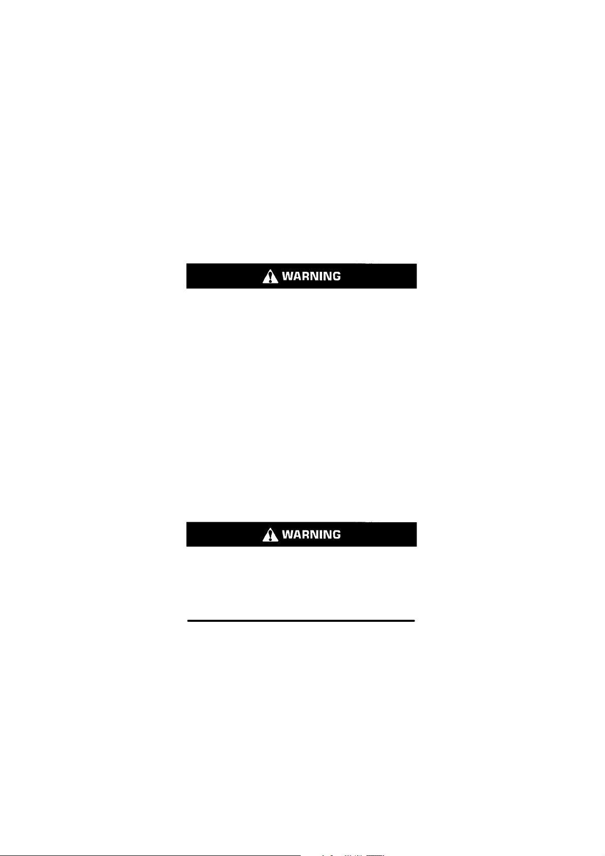
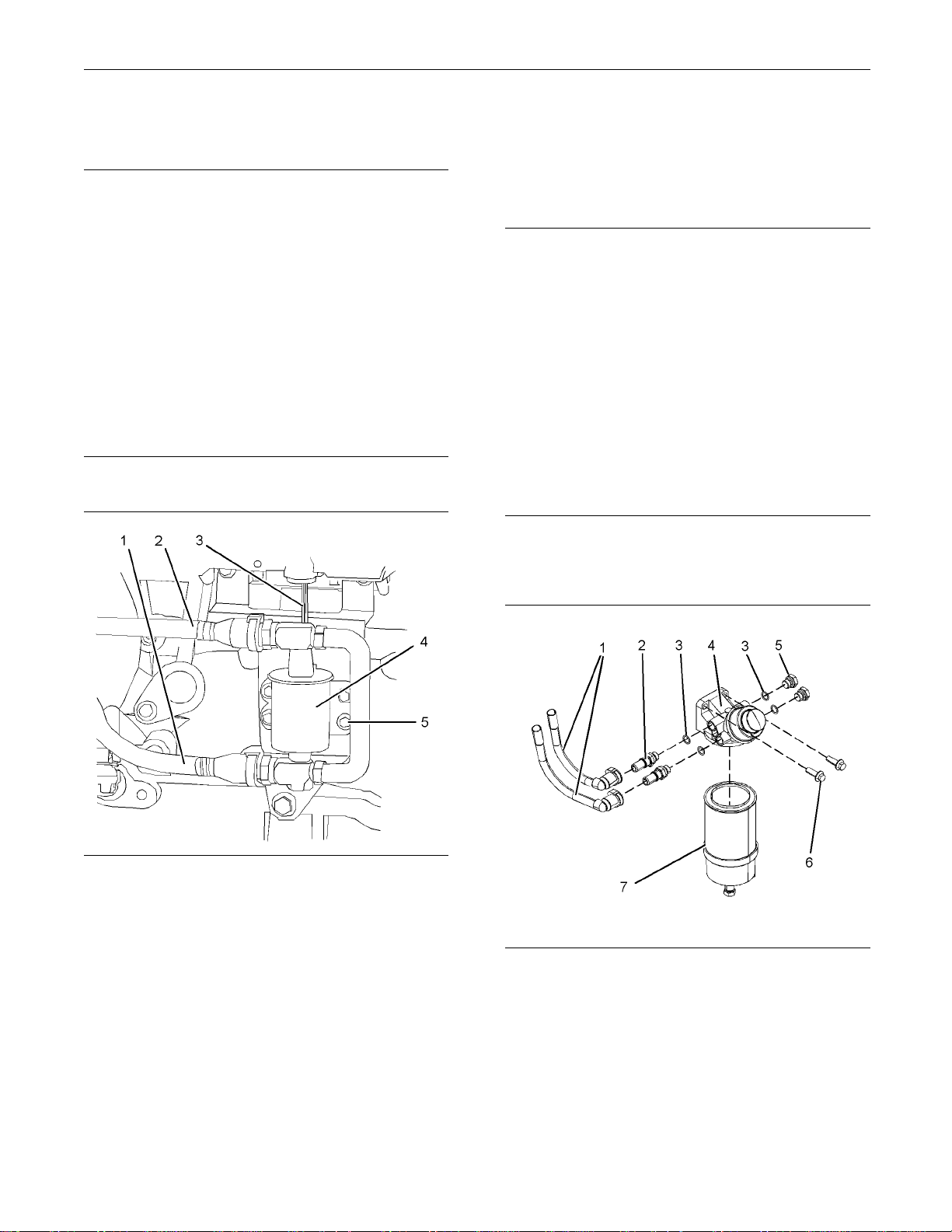
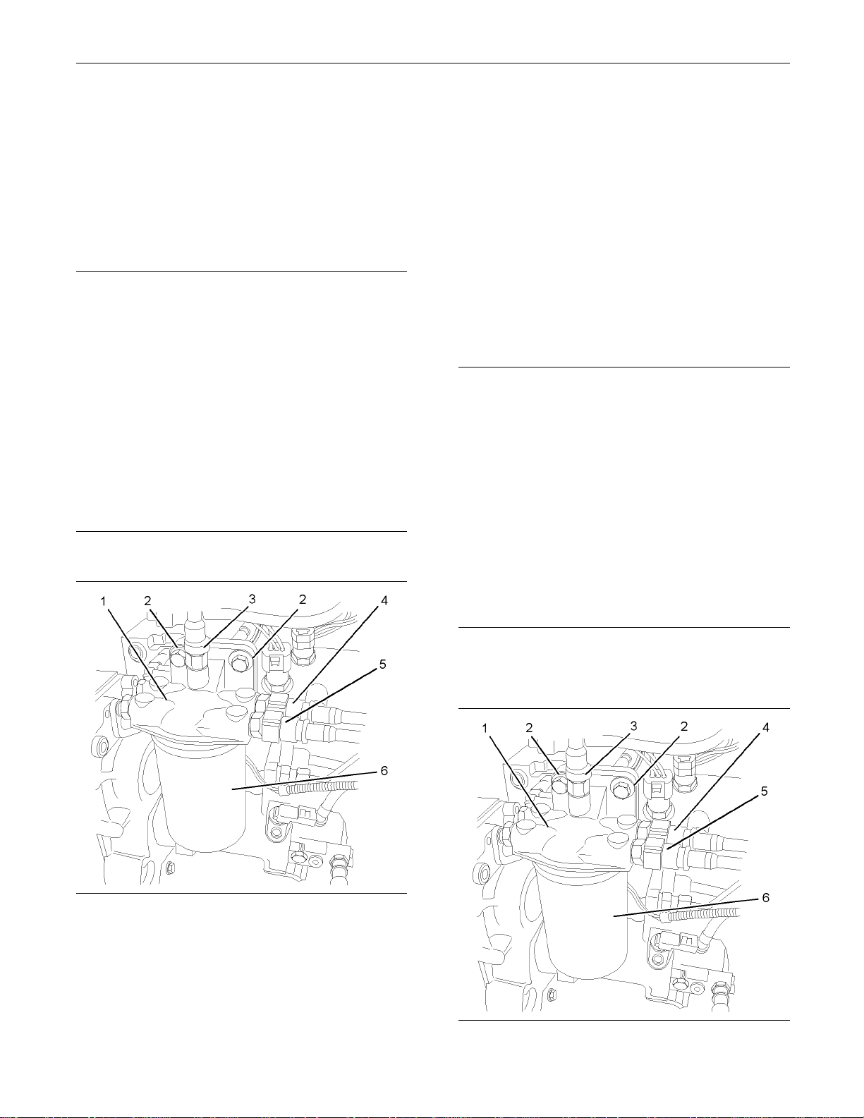
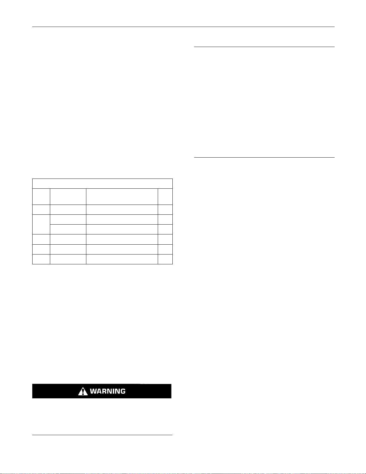
Illustration 1
Typical example
4. Disconnect the plastic tube assemblies (1). Plug
the tube assemblies with new plugs. Cap the open
connectors (2) on the fuel priming pump with new
caps.
5. Remove the primary filter (7) from the fuel priming
pump (4). Refer to Operation and Maintenance
Manual, “Fuel System Primary Filter (Water
Seperator) Element - Replace”.
g01181971
1. Isolate th
2. Makeatemporaryidentificationmarkonthe
plastic tu
correct position of the tube assemblies.
3. Place a sui
pump in order to catch any fuel that might
be spilled. Drain the primary filter (7). Refer
to Operat
System Primary Filter (Water Seperator) Element
-Replace”.
Note: Clean up any spillage of fuel immediately.
e fuel supply.
be assemblies (1) in order to show the
table container below the fuel priming
ion and Maintenance Manual, “Fuel
6. Remove the two setscrews (6) from the fuel
priming pump (4). Remove the fuel priming pump
(4) from the mounting bracket.
7. If necessary, follow Steps 7.a through 7.c in order
to disassemble the fuel priming pump (4).
a. Remove the connectors (2) from the fuel
priming pump (4).
b. Remove the plugs (5) from the fuel priming
pump (4).
c. Remove the O-ring seals (3) from the
connectors (2) and the plugs (5). Discard the
O-ring seals.
Page 5
SENR9983 5
Disassembly and Assembly Section
Removal Procedure (Electric Fuel
Priming Pump)
NOTICE
Ensure that all adjustments and repairs that are
carried out to the fuel system are performed by
authorised personnel that have the correct training.
Before begining ANY work on the fuel system, refer to Operation and Maintenance Manual, “General Hazard Information and High Pressure Fuel
Lines” for safety information.
Refer to Testing and Adjusting Manual, “Cleanliness of Fuel System Components” for detailed
information on the standards of cleanliness that
must be observed during ALL work on the fuel
system.
1. Isolate the fuel supply.
7. Remove the e lectric priming pump (4) from the
mounting brack
Installation P
et.
rocedure (Manual
Priming Pump)
NOTICE
Ensure that all adjustments and repairs that are
carried out to the fuel system are performed by
authorised pe
ing.
Before begin
fer to Operation and Maintenance Manual, “General Hazard Information and High Pressure Fuel
Lines” for sa
Refer to Testing and Adjusting Manual, “Cleanliness of Fue
information on the standards of cleanline ss that
must be observed during ALL work on the fuel
system.
1. Ensure that the fuel priming pump (4) is clean and
free from we
the fuel priming pump.
rsonnel that have the correct train-
ing ANY work on the fuel system, re-
fety information.
l System Components” for detailed
ar or damage. If necessary, replace
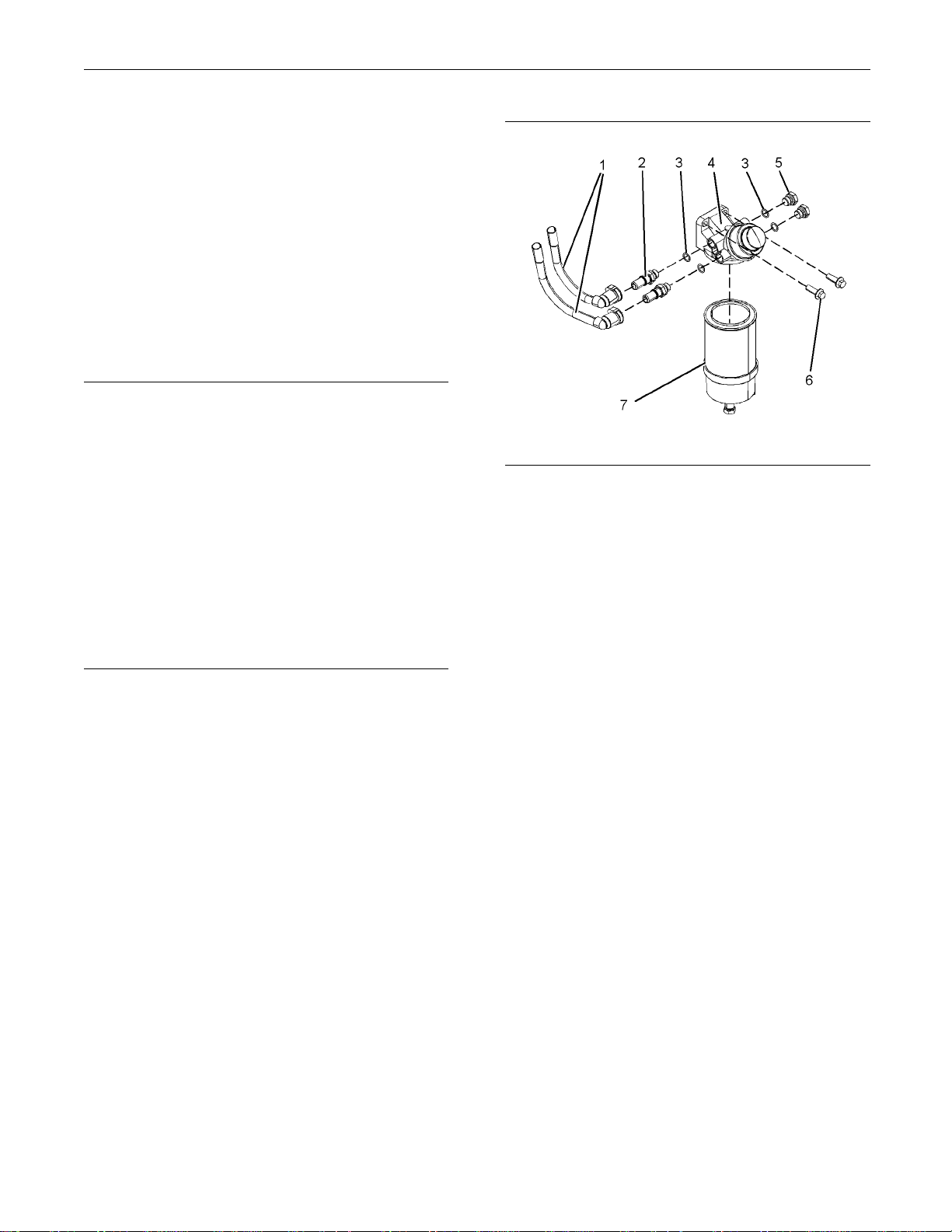
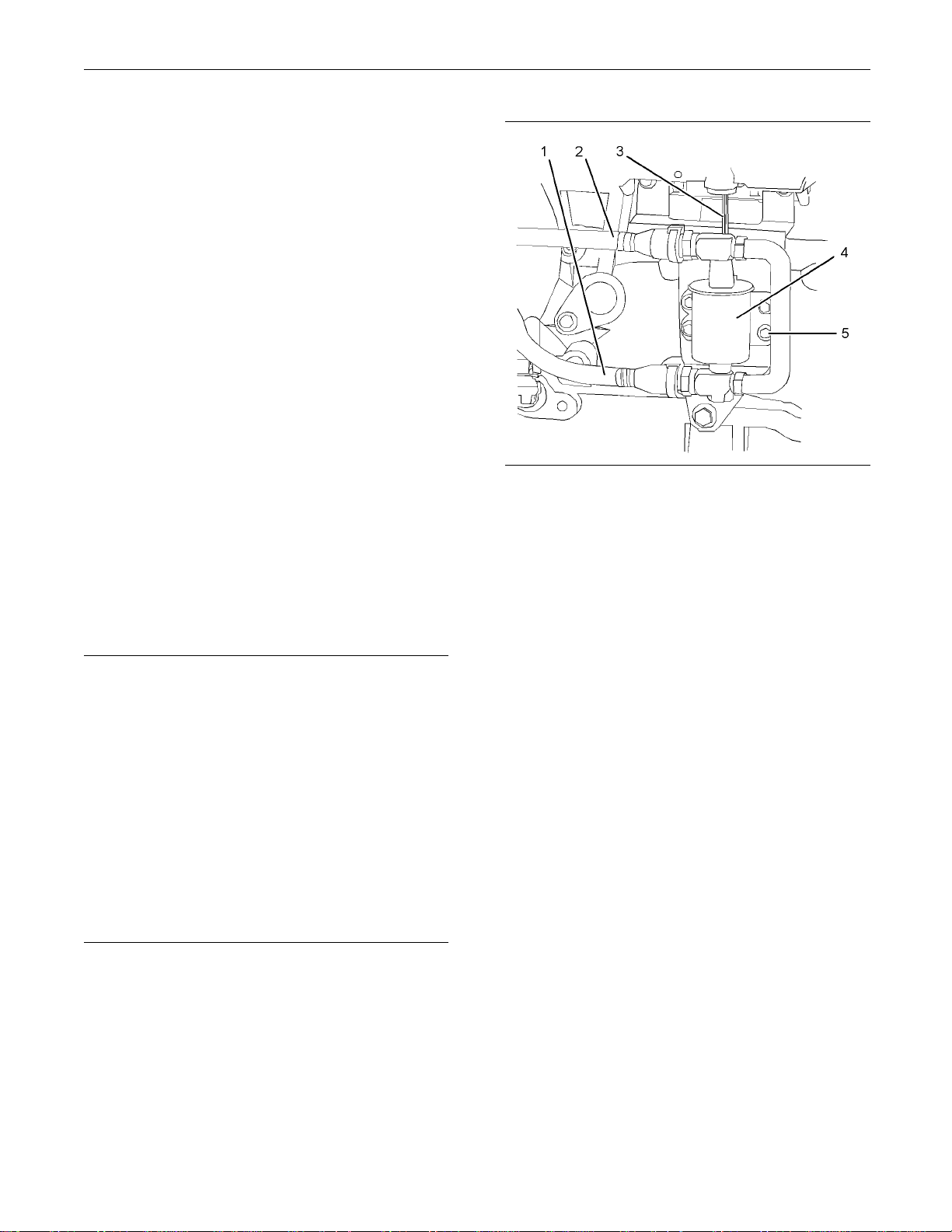
Illustration 2
Typical exam p le
2. Isolate the electrical supply.
3. Disconnect the electrical lead (3) for the electric
priming pump (4).
4. Makeatemporaryidentificationmarkonthe
plastic tube assemblies (1) and (2) in order to
show the correct position of the tube assemblies.
5. Disconnect the plastic tube assemblies (1) and (2).
Plug the tube assemblies with new plugs. Cap the
ports in the fuel priming pump (4) with new caps.
6. Remove the four setscrews (5) from the electric
priming pump (4).
g01186418
Illustration 3
Typical example
2. If necessary, follow Steps 2.a through 2.d in order
to assemble the fuel priming pump (4).
a. Install new O-ring seals (3) to the connectors
(2) and to the plugs (5).
b. Install the connectors (2) to the fuel priming
pump (4).
c. Install the plugs (5) to the fuel priming pump (4).
g01181971
Page 6
6 SENR9983
Disassembly and Assembly Section
d. Tighten the plugs and the connectors to a
torque of 20 N·m
3. Position the fuel priming pump (4) on the mounting
bracket. Inst
primingpump.Tightenthesetscrewstoatorque
of 44 N·m (32 lb ft).
4. Remove the plugs from the plastic tube
assemblies. Remove the caps from the
connectors.
5. Connect the plastic tube assemblies (1) to the
connectors (
Note: Ensure that the plastic tube assemblies are
installed in
6. Install a new primary filter (7) to the fuel priming
pump (4). Ref
Manual, “Fuel System Primary Filter (Water
Seperator) Element - Replace”.
7. Restore the fuel supply.
8. Prime the fu
Maintenance Manual, “Fuel System - Prime”.
all the two setscrews (6) to the fuel
2).
the original positions.
el system. Refer to Operation and
(14 lb ft).
er to Operation and Maintenance
Illustration 4
Typical example
2. Position the electric priming pump (4) on the
mounting bracket. Install the four setscrews (5) to
the electric priming pump (4).
g01186418
Installation Procedure (Electric
Fuel Primin
Ensure that all adjustments and repairs that are
carried out
authorised personnel that have the correct training.
Before begining ANY work on the fuel system, refer to Operation and Maintenance Manual, “General Hazar
Lines” for safety information.
Refer to T
liness of Fuel System Components” for detailed
information on the standards of cleanliness that
must be ob
system.
1. Ensure th
and free from wear or damage. If necessary,
replace the electric priming pump.
g Pump)
NOTICE
to the fuel system a re performed by
d Information and High Pressure Fuel
esting and Adjusting Manual, “Clean-
served during ALL work on the fuel
at the electric priming pump (4) is clean
3. Tighten the setscrews (5) to a torque of 9 N·m
(79 lb in).
4. Remove the plugs from the plastic tube
assemblies. Remove the caps from the electric
priming pump.
5. Connect the plastic tube assemblies (1) and (2) to
the electric priming pump (4).
Note: Ensure that the plastic tube assemblies are
installed in the original positions.
6. Connect the electrical lead (3) for the electric
priming pump (4).
7. Restore the electrical supply.
8. Restore the fuel supply.
9. Prime the fuel system. Refer to Operation and
Maintenance Manual, “Fuel System - Prime”.
Page 7
SENR9983 7
Disassembly and Assembly Section
i02295889
Fuel Filter Base - Remove and
Install
(Secondary Fue
Removal Procedure
Ensure that all adjustments and repairs that are
carried out to t
authorised personnel that have the correct training.
Before begining ANY work on the fuel system, refer to Operation and Maintenance Manual, “General Hazard In
Lines” for safety information.
Refer to Test
liness of Fuel System Components” for detailed
information on the standards of cleanliness that
must be obser
system.
he fuel system are performed by
formation and High Pressure Fuel
ing and Adjusting Manual, “Clean-
ved during ALL work on the fuel
l Filter)
NOTICE
4. Disconnect the plastic tube assemblies (3), (4)
and (5) from the
tube assemblies with new plugs. Cap the ports in
the fuel filter base with new caps.
5. Remove the fuel filter (6). Refer to Operation and
Maintenance Manual, “Fuel System Secondary
Filter - Repl
6. Remove the two setscrews (2) from the fuel filter
base (1). Rem
mounting bracket.
Note: Do not d
Installatio
Ensure that al
carried out to the fuel system are performed by
authorised personnel that have the correct training.
Before begining ANY work on the fuel system, refer to Opera
eral Hazard Information and High Pressure Fuel
Lines” for s afety information.
fuel filter base (1). Plug the plastic
ace”.
ove the fuel filter base from the
isassemble the fuel filter base.
n Procedure
NOTICE
l adjustments and repairs that are
tion and Maintenance Manual, “Gen-
1. Isolate the f
Illustration 5
Typical exam p le
2. Make temporary identification marks on the plastic
tube assemblies (3), (4) and (5) in order to show
the correct position of the tube assemblies.
uel supply.
g01165584
Refer to Testing and Adjusting Manual, “Cleanliness of Fuel System Components” for detailed
informatio
must be observed during ALL work on the fuel
system.
1. Ensure that the fuel filter base (1) is clean and free
from damage. If necessary, replace the complete
fuel filte
n on the standards of cleanliness that
r base and filter assembly.
3. Place a suitable container below the fuel filter base
in order to catch any fuel that might be spilled.
Note: Clean up any spillage of fuel immediately.
Illustration 6
Typical example
g01165584
Page 8

8 SENR9983
Disassembly and Assembly Section
2. Position the fuel filter base (1) on the mounting
bracket. Insta
setscrews to a torque of 44 N·m (32 lb ft).
3. Remove the plu
assemblies. Remove the caps from the ports in
the fuel filter base.
Ensure that th
in the original positions. Failure to connect the plastic
tube assemblies to the correct ports will allow contamination to en
cause serious damage to the engine.
4. Connect the p
(5) to the fuel filter base (1).
Note: Ensure
installed in the original positions. Failure to connect
the plastic tube assemblies to the correct ports
will allow c
Contaminated fuel will cause serious damage to the
engine.
5. If necessary, install a new fuel filter (6) to the
fuel filter base (1). Refer to Operation and
Maintenanc
Filter - Replace” for the correct procedure.
6. Restore th
End By:
ll the setscrews (2). Tighten the
gs from the plastic tube
NOTICE
e plastic tube assemblies are installed
ter the fuel system. Contaminated fuel will
lastic tube assemblies (3), (4) and
that the plastic tube assemblies are
ontamination to enter the fuel system.
e Manual, “Fuel System Secondary
e fuel supply.
i02296828
Fuel Transfer Pump - Remove
Removal Proced
Ensure that all
carried out to the fuel system are performed by
authorised personnel that have the correct training.
Before begining ANY work on the fuel system, refer to Operati
eral Hazard Information and High Pressure Fuel
Lines” for s afety information.
Refer to Testing and Adjusting Manual, “Cleanliness of Fuel System Components” for detailed
information
must be observed during ALL work on the fuel
system.
1. Isolate the fuel supply.
2. Place a suita
pump (1) in order to catch any fuel that might be
spilled.
Note: Clean up any spillage of fuel immediately.
adjustments and repairs that are
on and Maintenance Manual, “Gen-
on the standards of cleanliness that
ble container below the fuel transfer
ure
NOTICE
a. Remove the air from the fuel system. Refer to
Operation and Maintenance Manual, “Fuel System
- Prime”.
Page 9
SENR9983 9
Disassembly and Assembly Section
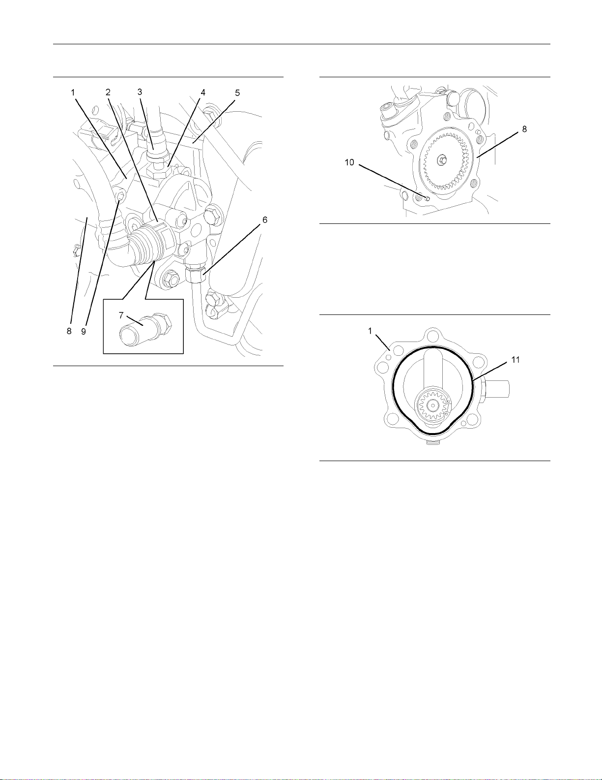
ion 7
Illustrat
Typical exam p le
g01162545
3. Remove the plastic tube assembly (2) from the
fuel transfer pump (1).
4. Disconnect the plastic tube assembly (3) from the
outlet of the fuel transfer pump (1).
5. Remove the connector (4) from the fuel transfer
pump (1). Remove the O-ring seal (not shown)
from the c
onnector (4). Discard the O-ring seal.
If necessary, remove the connector (7) from the
fuel tran
sfer pump (1). Remove the O-ring seal
(not shown) from the connector (7). Discard the
O-ring seal.
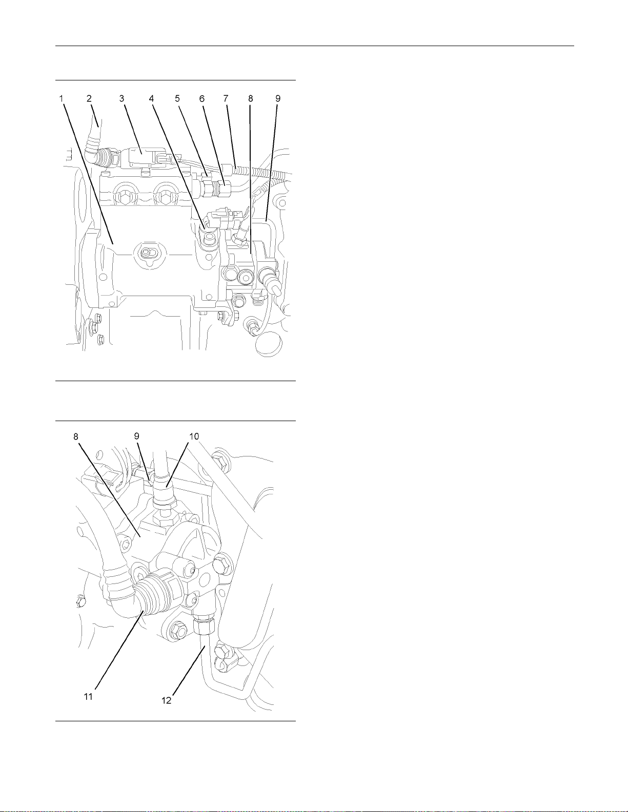
Illustration 8
g01162543
10. Remove fuel transfer pump (1) from the fuel
injection pump (8).
Note: Do not remove the dowels (10) from the fuel
injection pump.
Illustrat
ion 9
g01162544
11. Remove the O-ring seal (11) from the fuel transfer
pump (1). D
iscard the O-ring seal.
6. Remove the tube assembly (6) for the fuel return
from the fuel transfer pump and the cylinder head.
Note: Disconnect the tube assembly at the fuel
transfer pump first in order to drain the fuel from the
cylinde
r head.
7. Remove the tube assembly (5) for the engine oil
supply f
rom the fuel injection pump (8).
8. Plug or cap all open ports and tube assemblies
immedi
ately with new plugs or caps.
9. Use an allen wrench with a ball end in order to
remove
the five allen head screws (9) that secure
the fuel transfer pump to the fuel injection pump
(8).
Page 10
10 SENR9983
Disassembly and Assembly Section
i02296829
Fuel Transfer Pump - Install
Installation P
rocedure
NOTICE
Ensure that all
adjustments and repairs that are
carried out to the fuel system are performed by
authorised personnel that have the correct training.
Before begining ANY work on the fuel system, refer to Operati
on and Maintenance Manual, “General Hazard Information and High Pressure Fuel
Lines” for safety information.
Refer to Testing and Adjusting Manual, “Cleanliness of Fuel System Components” for detailed
information
on the standards of cleanliness that
must be observed during ALL work on the fuel
system.
1. Ensure that the mating faces of the fuel injection
pump (8) and the fuel transfer pump (1) are clean
and free fro
m damage.
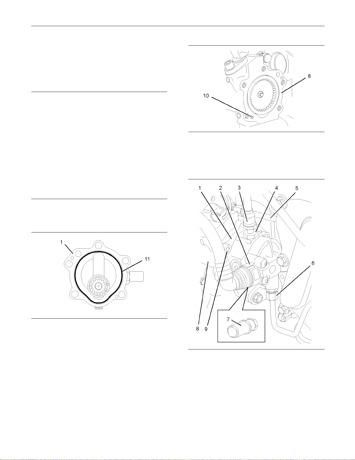
Illustration 11
g01162543
3. Align the holes in the fuel transfer pump (1) with
thedowels(10)inthefuelinjectionpump(8).
Install the fuel transfer pump to the fuel injection
pump.
Illustration 10
g01162544
2. Install a new O-ring seal (11) to fuel transfer pump
(1). Lubricate the O-ring seal with clean engine oil.
ration 12
Illust
Typical example
g01162545
4. Use an allen wrench with a ball end to install the
five allen head screws (9). Tighten the allen head
screws
toatorqueof30N·m(22lbft).
5. Remove the plugs and the caps from the ports
and tub
e assemblies.
Page 11
SENR9983 11
Disassembly and Assembly Section
6. Install the tube assembly (5) for the engine oil
supply to the fu
cylinder block.
7. Install the tu
the fuel transfer pump (1) and to the cylinder head.
el injection pump (8) and to the
be assembly (6) for the fuel return to
NOTICE
Ensure that all adjustments and repairs that are
carried out to t
he fuel system are performed by
authorised personnel that have the correct training.
8. Install a new O
-ring seal (not shown) to the
connector (4). Install the connector (4) to the fuel
transfer pump (1). Tighten the connector to torque
of 15 N·m (11 l
b ft).
9. If necessary, install a new O-ring seal (not shown)
to the connec
tor (7) and install the connector (7) to
the fuel transfer pump (1). Tighten the connector
to torque of 15 N·m (11 lb ft).
10. Connect the plastic tube assembly (3) to the
outlet of the fuel transfer pump (1).
11. Install the plastic tube assembly (2) to the fuel
transfer pump (1).
12. Restore the fuel supply.
13. Remove the a
ir from the fuel system. Refer to
Testing and Adjusting Manual, “Fuel System Prime”.
i02295890
Fuel Injection Lines - Remov e
Before begining ANY work on the fuel system, refer to Operation and Maintenance Manual, “General Hazard In
formation and High Pressure Fuel
Lines” for s afety information.
Refer to Testi
ng and Adjusting Manual, “Cleanliness of Fuel System Components” for detailed
information on the standards of cleanliness that
must be obser
ved during ALL work on the fuel
system.
1. Isolate the f
uel supply.
2. Isolate the electrical supply.
Removal Procedure
Table 1
Required Tools
Too l
A
Contact with high pressure fuel may cause fluid
penetration and burn hazards. High pressure fuel spray may cause a fire hazard. Failure to follow these inspection, maintenance and service instructions may cause personal injury or death.
Part
Number
U5MK1124
Part Name Qty
Cap Kit 1
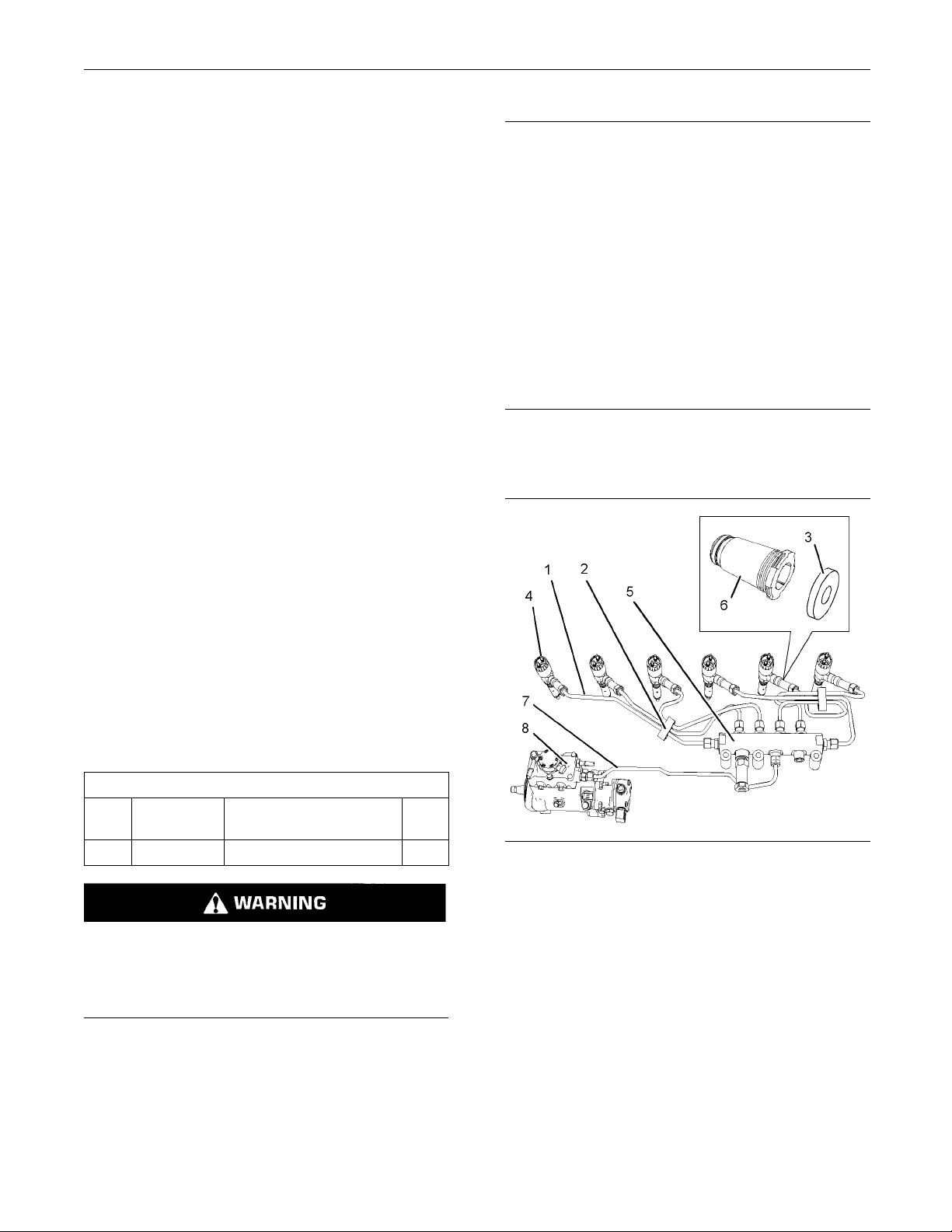
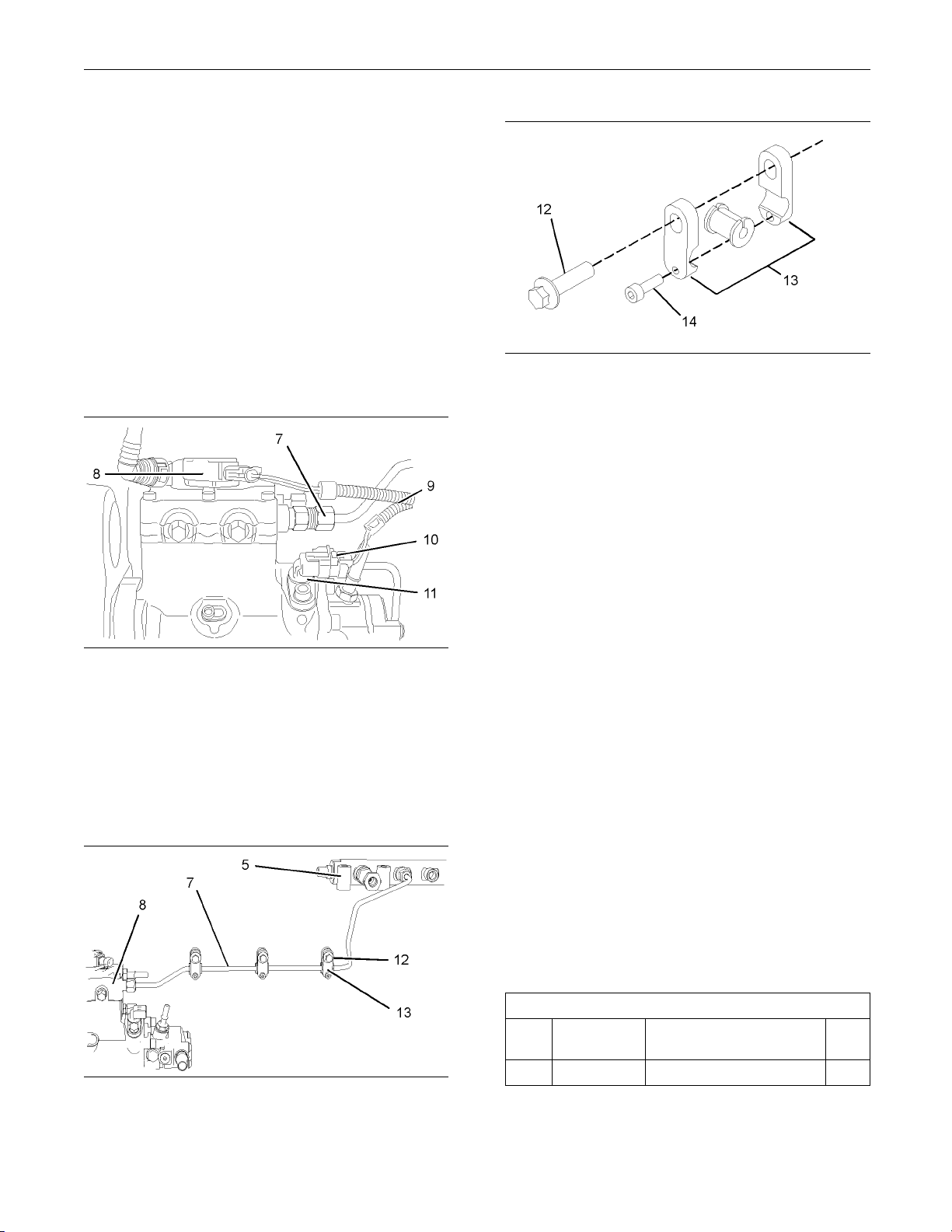
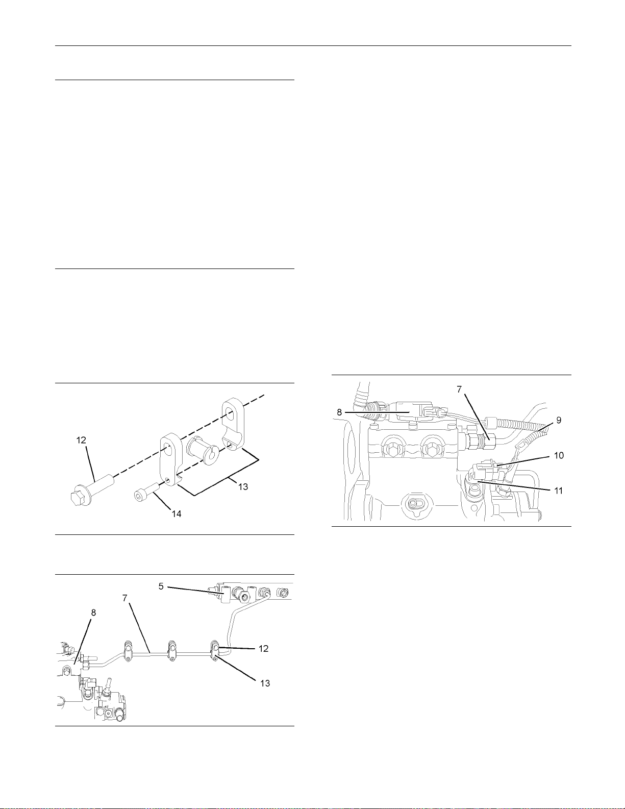
Illustration 13
Typical example
g01178882
3. Remove the two plastic clamps (2) from the fuel
injection lines (1). Discard the plastic clamps.
4. Slide the dust seal (3) from the nut on the fuel
injection line (1).
5. Disconnect the fuel injection line (1) at the
electronic unit injector (4).
6. Disconnect the fuel injection line (1) at the fuel
manifold (5).
7. Remove the fuel injection line (1). Discard the fuel
injection line.
Note: Clean up any spillage of fuel immediately.
Page 12
12 SENR9983
Disassembly and Assembly Section
8. Plug the open port in the fuel manifold (5)
immediately. U
se Tooling (A) in order to plug the
open port in the fuel manifold.
9. Remove the sea
l (6) from the electronic unit
injector (4) and the base of the valve mechanism
cover (not shown).
Note: The seal can be damaged by contact with fuel.
10. Plug the open p
ort in electronic unit injector (4)
immediately. Use Tooling (A) in order to plug the
open port in the electronic unit injector.
11. Repeat Steps 4 through 11 in order to remove
the remaining fuel injection lines from the fuel
manifold to t
Illustration 14
Typical Exam ple
he electronic unit injectors.
g01198424
12. Disconnect the harness assembly (9) from the
fuel injection pump (8). Slide the locking tab
(10) into the unlocked position. Disconnect the
harness assembly (9) from the position sensor
(11). Position the harness assembly (9) so that
the harness assembly is clear of the fuel injection
line (7).
Illustration 16
Assembly of the tube clip
g01208399
13. Remove the fasteners (12) from the three tube
clips (13) that secure the fuel injection line (7).
Loosen the three allen head screws (14). Position
the tube clips in order to allow removal of the fuel
injection line.
14. Disconnect the fuel injection line (7) at the fuel
injection pump (8).
15. Disconnect the fuel injection line (7) at the fuel
manifold (5).
16. Plug all open ports immediately. Use Tooling (A)
in order to plug the open ports in the fuel manifold
(5) and in the fuel injection pump (8).
17. Remove the fuel injection line (7).
Note: Clean up any spillage of fuel immediately.
18. Remove the allen head screws (14) and the
assemblies of the three tube clips (13) from fuel
injection line (7). Discard the fuel injection line.
i02295912
Illustration 15
g01208398
Fuel Inje
ction Lines - Install
Installation Procedure
Table 2
Tools
Part Name
Tool
A
Part
Number
27610294
Required
Injector Pipe Nut Tool 1
Qty
Page 13
SENR9983 13
Disassembly and Assembly Section
1. Loosely install the assemblies of the three tube
NOTICE
Ensure that all adjustments and repairs that are
carried out to t
he fuel system are performed by
authorised personnel that have the correct train-
clips (13) and t
fuel injection line (7).
2. Place the fuel
he allen head screws (14) to the
injection line (7) in position.
ing.
3. Remove the caps from the port in the fuel injection
Before begining ANY work on the fuel system, refer to Operation and Maintenance Manual, “General Hazard In
formation and High Pressure Fuel
pump (8) and fr
manifold (5). Remove the caps from the new fuel
injection line (7).
om the appropriate port in the fuel
Lines” for safety information.
4. Loosely connect the nuts at both ends of the fuel
Refer to Testi
ng and Adjusting Manual, “Cleanliness of Fuel System Components” for detailed
information on the standards of cleanliness that
must be obser
ved during ALL work on the fuel
injection line (7), to the fuel manifold (5) and to
the fuel inje
ction pump (8). Ensure that the ends
of the fuel injection line are correctly seated in the
fuel injection pump and in the fuel manifold.
system.
5. Use Tooling (A) to tighten the nuts on the fuel
injectionline(7)toatorqueof30N·m(22lbft).
Note: The fol
in order to install the fuel injection lines when the
electronic unit injectors or the fuel manifold have
not been rem
or the fuel manifold have been removed, refer to
Disassembly and Assembly Manual, “Electronic Unit
Injector-I
lowing procedure should be adopted
oved. If the electronic unit injectors
nstall” and Disassembly and Assembly
6. Install the setscrews (12) for the three tube clips
(13) that secure the fuel injection line (7). Tighten
the setscre
ws (12) to a torque of 22 N·m (16 lb ft).
Tighten the M5 allen head screws (14) to a torque
of 10 N·m (89 lb in). Ensure that fuel injection line
does not co
ntact any other engine component.
Manual, “Fuel Manifold - Install” for more information.
Illustration 17
Assembly o f the tube clip
Illustration 18
g0120839
g01208398
9
Illustration 19
Typical example
g01198424
7. Connect the harness assembly (9) to the position
sensor (11). Slide the locking tab (10) into the
locked position. Connect the harness assembly
(9) to the fuel injection pump (8).
Page 14
14 SENR9983
Disassembly and Assembly Section
15. Install two new clamps (2) to the fuel injection
lines. Ensure t
order to retain the fuel injection lines.
hat the clamps are fully closed in
Illustration 20
Typical exam p le
8. Thoroughly clean the seal (6). Inspect the seal for
damage. If necessary, replace the seal.
Note: The seal can be damaged by contact with
fuel. If the seal has been in contact with fuel for a
prolonged period, the seal should be replaced.
g01178882
Note: Ensure t
any other engine component.
16. Restore the fu
17. Restore the electrical supply.
18. Remove the air from the fuel system. Refer to
the Operations and Maintenance Manual, “Fuel
System - Prim
hat fuel injection lines do not contact
el supply.
e”.
i02403286
Fuel Ma nifold ( R ail) - Remove
and Install
Removal Procedure
Start By:
a. Remove the fuel injection lines. Refer to
Disassembly and Assembly Manual, “Fuel
Injection Lines - Remove”.
9. Install the seal (6) to the electronic unit injector
(4). Ensure that the flange on the seal is flush with
the valve mechanism cover base.
10. Remove the caps from the new fuel injection line
(1). Ensure that a new dust seal (3) is installed
to the fuel injection line.
11. Remove the caps from the electronic unit injector
(4) and from the appropriate port in the fuel
manifold (5).
12. Loosely connect the nuts at both ends of the fuel
injection line (1), to the electronic unit injector (4)
and to the appropriate port in the fuel manifold
(5). Ensure that the ends of the fuel injection line
are correctly seated in the electronic unit injector
andinthefuelmanifold.
13. Use Tooling (A) to tighten the nuts on the fuel
injectionline(1)toatorqueof30N·m(22lbft).
Slide the dust seal (3) into position over the nut on
the fuel injection line. Ensure that the dust seal (3)
is in contact with the seal (6).
14. Follow Steps 8 through 13 in order to install the
remaining fuel injection lines.
b. If necessary, remove the fuel pressure sensor.
Refer to Disassembly and Assembly Manual,
“Fuel Pressure Sensor - Remove and Install”.
Contact with high pressure fuel may cause fluid
penetration and burn hazards. High pressure fuelspraymaycauseafirehazard.Failuretofollow these inspection, maintenance and service instructions ma y cause personal injury or death.
NOTICE
Ensure that all adjustments and repairs that are
carried ou
authorised personnel that have the correct training.
Before begining ANY work on the fuel system, refer to Operation and Maintenance Manual, “General Haza
Lines” for s afety information.
Refer to T
liness of Fuel System Components” for detailed
information on the standards of cleanliness that
must be ob
system.
t to the fuel system are performed by
rd Information and High Pressure Fuel
esting and Adjusting Manual, “Clean-
served during ALL work on the fuel
Page 15
SENR9983 15
Disassembly and Assembly Section
1. Ensure that all ports on the fuel manifold are
capped. Ensure
that the fuel manifold is externally
clean and free from damage.
Illustration 21
The fuel m anifold is shown with fuel injection lines in position.
g01190733
1. If the fuel sensor (4) has not been removed from
the fuel manifold (1), slide the locking tab (3) into
the unlocked position. Disconnect the plug on
the harness assembly (6) from the fuel pressure
sensor (4).
2. Disconnect the tube assembly (5) from the fuel
pressure relief valve on the fuel manifold (1).
Immediately cap the open port in the fuel manifold
(1) with a new cap. Immediately plug the open end
of the tube assembly (5) with a new plug.
3. Remove the three setscrews (2) from the fuel
manifold (1).
4. Remove the fuel manifold (1) from the mounting
bracket (7).
Note: Do not in
stall a fuel manifold that has not
been capped. All caps must be left in place until the
fuel injection lines or the fuel pressure sensor are
installed.
Illustration 22
The fuel manifold is shown with fuel injection lines in position.
g01190733
2. Position the fuel manifold (1) on the mounting
bracket (7).
3. Install the three setscrews (2) to the fuel manifold
(1)fingertight.
4. Install a new set of fuel injection lines and seals.
Refer to Disassembly and Assembly Manual,
“Fuel Injection Lines - Install” for more information.
Installation Procedure
NOTICE
Ensure that all adjustments and repairs that are
carried out to the fuel system are performed by
authorised personnel that have the correct training.
Before begining ANY work on the fuel system, refer to Operation and Maintenance Manual, “General Hazard Information and High Pressure Fuel
Lines” for safety information.
Refer to Testing and Adjusting Manual, “Cleanliness of Fuel System Components” for detailed
information on the standards of cleanliness that
must be observed during ALL work on the fuel
system.
5. Tighten the setscrews (2) to a torque of 22 N·m
(16 lb ft).
6. Removetheplugfromthetubeassembly(5).
Remove the cap from the appropriate port in the
fuel manifold (1). Connect the tube assembly
(5) to the fuel pressure relief valve on the fuel
manifold (1).
7. If the fuel pressure sensor (4) was not removed
from the fuel manifold (1), connect the plug on
the harness assembly (6) to the fuel pressure
sensor (4). slide the locking tab (3) into the locked
position.
Page 16
16 SENR9983
Disassembly and Assembly Section
If the fuel pressure sensor (4) was removed from
the fuel manifo
sensor (4) and a new sealing washer. Refer
to Disassembly and Assembly Manual, “Fuel
Pressure Sens
information.
ld (1), install the fuel pressure
or - Revove and Install” for more
NOTICE
Ensure that all adjustments and repairs that are
carried out to t
he fuel system are performed by
authorised personnel that have the correct training.
8. Remove the ai
r from the fuel system. Refer to
Operation and Maintenance Manual, “Fuel System
-Prime”formoreinformation.
i02295929
Fuel Injection Pump - Remove
Removal Procedure
Table 3
Required Tools
Tool
A
A
B
C
D
Part
Number
21825576
27610289
27610290
27610212
27610286
-
Part Name Qty
Crankshaft Turning Tool 1
Crankshaft Turning Tool 1
Gear 1
Camshaft Timing Pin 1
Crankshaft Timing Pin 1
Cap
2
Before begining ANY work on the fuel system, refer to Operation and Maintenance Manual, “General Hazard In
formation and High Pressure Fuel
Lines” for s afety information.
Refer to Testi
ng and Adjusting Manual, “Cleanliness of Fuel System Components” for detailed
information on the standards of cleanliness that
must be obser
ved during ALL work on the fuel
system.
1. Isolate the f
uel supply.
2. Isolate the electrical supply.
3. Use Tooling (A) in order to rotate the crankshaft
so that number one piston is at top dead center
on the compr
ession stroke. Refer to Testing and
Adjusting Manual, “Finding Top Centre Position for
No.1 Piston”.
4. Use Tooling (B) in order to lock the camshaft in
the correct position. Use Tooling (C) in order to
lock the cra
nkshaft in the correct position. Refer to
Disassembly and Assembly, “Gear Group (Front)
- Remove” for the correct procedure.
Start By:
a. If necessary, remove the fuel filter base. Refer to
Disassembly and Assembly Manual, “Fuel Filter
Base - Remove and Install”.
b. If necessary, remove the fuel priming pump. Refer
to Disassembly and Assembly Manual, “Fuel
PrimingPump-Remove”.
c. Remove the front cover. Refer to Disassembly
and Assembly Manual, “Front Cover - Remove
and Install”.
Note: Either Tooling (A) can be used. Use the Tooling
that is most suitable.
Contact with high pressure fuel may cause fluid
penetration and burn hazards. High pressure fuel spray may cause a fire hazard. Failure to follow these inspection, maintenance and service instructions may cause personal injury or death.
5. Remove the backlash from the fuel pump gear.
Lock the fuel injection pump in the correct
position a
nd remove the fuel pump gear. Refer to
Disassembly and Assembly, “Fuel Pump Gear Remove and Install” for the correct procedure.
Page 17
SENR9983 17
Disassembly and Assembly Section
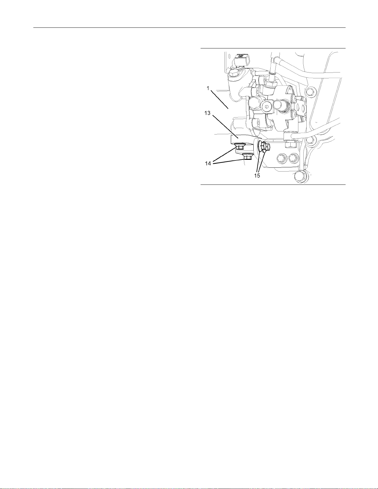
6. Place a suitable container below the fuel injection
pump (1) in orde
r to catch any fuel that might be
spilled.
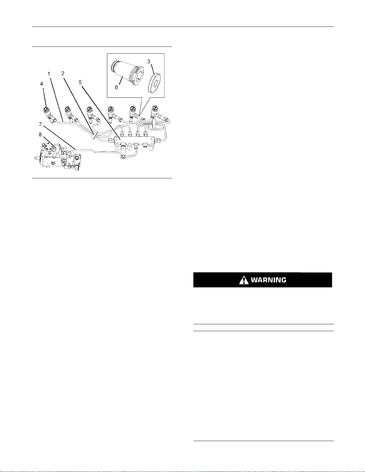
ion 2 3
Illustrat
Typical exam p le
g01173307
Note: Clean up
any spillage of fuel immediately.
7. Disconnect the plastic tube assembly (2) from the
fuel injectio
n pump (1).
8. Disconnect the engine wiring harness (7) from the
solenoid (3) o
f the fuel injection pump. Disconnect
the engine wiring harness (7) from the position
sensor (4) for the fuel injection pump.
Note: The engine wiring harness should be
positioned in order to avoid an obstruction to the fuel
injection pu
mp.
9. Remove the plastic tube assembly (11) from the
fuel transfe
r pump (8).
10. Disconnect the plastic tube assembly (10) from
the outlet o
f the fuel transfer pump (8).
11. Disconnect the plastic tube assembly (5) from the
fuel inject
ion pump (1).
12. Remove the tube assembly (12) for the fuel return
from the fue
l transfer pump and the cylinder head.
Note: Disconnect the tube assembly at the fuel
transfer pu
mp first in order to drain the fuel from the
cylinder head.
Illustration 24
Typical exam p le
g01173310
13. Remove the t
ube assembly (9) for the engine oil
supply to the fuel injection pump (1).
14. Plug or cap
all open ports and tube assemblies
immediately with new plugs or caps.
15. Remove the
fuel injection line (6) that connects
the fuel injection pump to the fuel manifold. Refer
to Disassembly and Assembly Manual, “Fuel
Injection
Lines - Remove”. Use Tooling (D) in
order to plug the open ports in the fuel injection
pump and in the fuel manifold. Discard the fuel
injectio
nline.
Page 18
18 SENR9983
Disassembly and Assembly Section
19. Remove the O-ring seal (21) from the fuel
injection pump
(1). Discard the O-ring seal.
20. If necessary, remove the position sensor (4) from
the fuel injec
tion pump (1). Refer to Disassembly
and Assembly Manual, “Position Sensor (Fuel
Injection Pump) - Remove and Install”.
21. If necessary, remove the fuel transfer pump
(8) from the fuel injection pump (1). Refer to
Disassembly
and Assembly Manual, “Fuel
Transfer Pump - Remove”.
i02295933
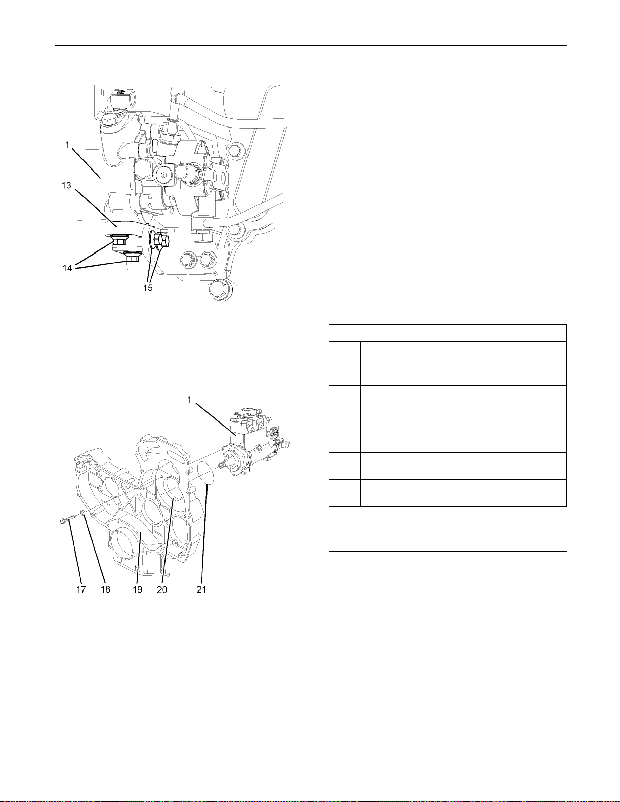
Illustration 25
g01208416
16. Remove the two setscrews (15). Remove the two
setscrews (14) and remove the support bracket
(13) from the fuel injection pump (1).
Fuel Inject
ionPump-Install
Installation Procedure
Table 4
Required To
Too l
A
A
B 27610212
C
E 27610302
F 21820221
Part
Number
21825576
27610289
27610290
27610286
Crankshaft Turning Tool
Crankshaft Turning Tool
Gear
Camshaft Timing Pin
Crankshaft Timing Pin
Fuel Injection Pump
Timing Tool
POWERPART
Rubber Grease
Note: EitherTooling(A)canbeused.UsetheTooling
that is most suitable.
ols
Part Description Qty
1
1
1
1
1
1
-
Illustration 26
Typical exam p le
g01173314
17. Remove the three setscrews (17) and sealing
washers (18). Discard the sealing washers.
Note: The fuel injection pump should be supported
by hand as the setscrews are removed.
18. Carefully remove the fuel injection pump (1) from
the front housing (19). Ensure that the bore (20)
in the front housing is not damaged as the fuel
injection pump is removed.
NOTICE
Ensure that all adjustments and repairs that are
carried out to the fuel system are performed by
authorised personnel that have the correct training.
Before begining ANY work on the fuel system, refer to Operation and Maintenance Manual, “General Hazard Information and High Pressure Fuel
Lines” for s afety information.
Refer to Testing and Adjusting Manual, “Cleanliness of Fuel System Components” for detailed
information on the standards of cleanliness that
must be observed during ALL work on the fuel
system.
Page 19
SENR9983 19
Disassembly and Assembly Section
3. If the fuel injection pump timing has been lost
follow Steps 3.
a through 3.e in order to reset the
fuel injection pump timing.
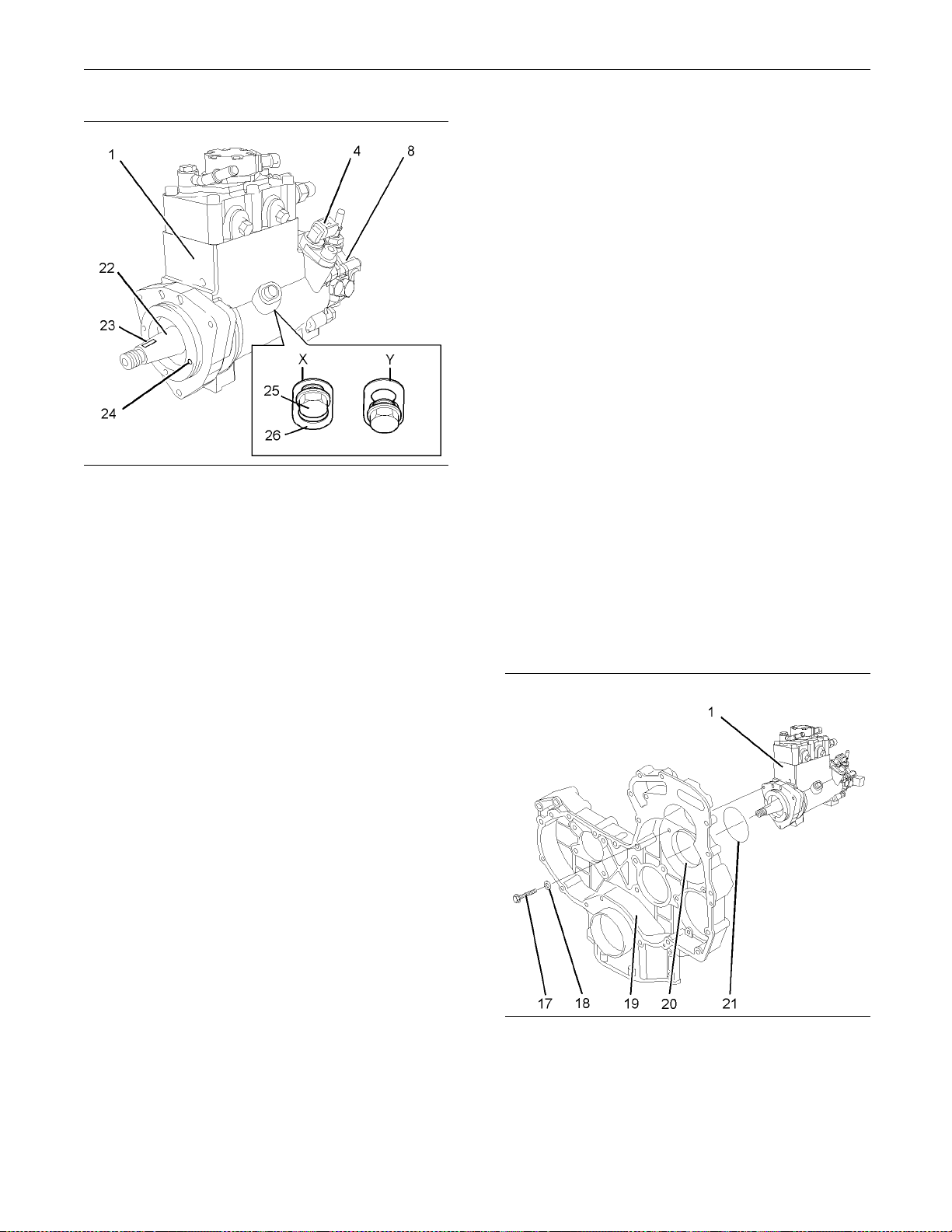
Illustration 27
1. If the fuel injection pump was previously
disassembled, follow Steps 1.a and 1.b in order to
assemble the fuel injection pump.
a. Install the fuel transfer pump (8) to the fuel
injection pump (1). Refer to Disassembly and
Assembly Manual, “Fuel Transfer Pump Install”.
b. Install the position sensor (4) to the fuel
injection pump (1). Refer to Disassembly and
Assembly Manual, “Position Sensor (Fuel
Injection Pump) - Remove and Install”.
g01174932
a. If necessary,
loosen the locking screw (25) on
the fuel injection pump. Slide the spacer (26)
into position (X). Tighten the locking screw (25)
toatorqueof
9N·m(80lbin).Thiswillprevent
the locking screw from tightening against the
shaft (22).
The fuel injection pump is now unlocked.
b. Position Too
ling (E) onto the shaft (22) of the
fuel injection pump. Align the lever of Tooling
(E) with the key slot (23) in the fuel injection
pump. Engage
the lever into the key slot.
c. Use the lever of Tooling (E) to rotate the shaft
(22) until t
he pin of Tooling (E) can be engaged
into the hole (24). Engage the pin of Tooling
(E) into the hole.
d. Loosen the locking screw (25) in the fuel
injection pump. Slide the spacer (26) into
position (
Y). Tighten the locking screw (25)
against the shaft of the fuel injection pump to a
torqueof9N·m(80lbin).
The fuel injection pump is now locked.
e. Remove too
ling (E).
Note: A new fuel injection pump assembly includes
the fuel transfer pump and the position sensor.
2. To check the fuel injection pump timing, follow
Steps 2.a and 2.b.
a. Position Tooling (E) onto the shaft (22) of the
fuel injection pump. Align the lever of Tooling
(E) with the key slot (23). Engage the lever into
the key slot.
b. Insert the locking pin of Tooling (E) into the
hole (24) in fuel injection pump.
If the locking pin can be inserted into the hole,
the fuel injection pump timing is correct.
If the locking pin cannot be inserted into the
hole, the fuel injection pump timing is not
correct.
Note: There should be no resistance when the
locking pin is inserted.
Illustration 28
Typical example
g01173314
4. Inspect the bore (20) in the front housing (19)
for damage. If the bore is damaged, replace
the front housing. Refer to Disassembly and
Assembly Manual, “Housing (Front) - Remove”
and Disassembly and Assembly Manual, “Housing
(Front) - Install”.
Page 20
20 SENR9983
Disassembly and Assembly Section
5. Use Tooling (F) to lubricate a new O-ring seal
(21). Install t
he O-ring seal onto the fuel injection
pump (1).
6. Align the hole
s in the fuel injection pump (1) with
the holes in the front housing (19). Carefully install
the fuel injection pump to the front housing.
Note: The fuel injection pump should be supported
by hand until the setscrews are installed.
7. Install the three setscrews (17) and three new
sealing washers (18). Tighten the setscrews to a
torque of 25 N
·m(18lbft).
8. If necessary, use Tooling (A) in order to rotate the
crankshaft s
o that number one piston is at top
dead center on the compression stroke. Refer
to Testing and Adjusting Manual, “Finding Top
Centre Posi
tion for No.1 Piston”.
9. Use Tooling (B) in order to lock the camshaft in
the correct
position. Use Tooling (C) in order to
lock the crankshaft in the correct position. Refer to
Disassembly and Assembly, “Gear Group (Front)
- Remove” f
or the correct procedure.
10. Install the fuel injection pump gear to the fuel
injection
pump. Refer to Disassembly and
Assembly Manual, “Fuel Injection Pump Gear Install” and refer to Disassembly and Assembly
Manual, “G
ear Group (Front) - Install”.
Note: Ensure that the spacer (26) on the fuel
injection
pump is in the unlocked position (X) after the
installation of fuel injection pump gear is completed.
Refer to Illustration 27.
Illustration 29
Typical example
g01208416
12. Position the support bracket (13) onto the fuel
injection pump (1). Install the two setscrews (14)
finger tight.
13. Install the two setscrews (15) finger tight.
14. Tighten the setscrews (15) to a torque of 22 N·m
(16 lb ft). the setscrews (14) to a torque of 22 N·m
(16 lb ft).
Some engines have a single M10 nut and a bolt in
place of the two setscrews (15). Tighten the nut
and bolt to a torque of 44 N·m (32.5 lb ft).
11. Install the front cover. Refer to Disassembly and
Assembly Manual, “Front Cover - Remove and
.
Install”
Note: Ensure that the fuel injection pump is not
stressed as the fasteners for the bracket are
tightened.
Page 21

SENR9983 21
Disassembly and Assembly Section
15. Remove the appropriate plugs and caps in order
to install tube
assembly (9) for the engine oil
supply to the fuel injection pump. Install the tube
assembly (9). Tighten the nuts at both ends of the
tube assembly
.
16. Remove the appropriate caps in order to install
the fuel inje
ction line (6). Install a new fuel injection
line (6) to the fuel injection pump and to the fuel
manifold. Refer to Disassembly and Assembly
Manual, “Fue
l Injection Lines - Install”.
17. Remove the plugs and caps from the remaining
ports and tub
eassemblies.
18. Install the tube assembly (12) for the fuel return
to the fuel tr
ansfer pump and to the cylinder
head. Tighten the nuts at both ends of the tube
assembly.
19. Install the plastic tube assembly (5) to the fuel
injection pump (1).
ion 3 0
Illustrat
Typical exam p le
g01173307
20. Install the plastic tube assembly (10) for the fuel
outlet to the fuel transfer pump (8).
21. Install the plastic tube assembly (11) to the fuel
transfer pump (8).
22. Connect the harness assembly (7) to the solenoid
(3) on the fuel injection pump. Connect the
harness as
sembly (7) to the position sensor (4) on
the fuel injection pump. Slide the locking tab (not
shown) into the locked position.
23. If necessary, install the fuel priming pump. Refer
to Disassembly and Assembly Manual, “Fuel
Priming P
ump - Remove and Install”.
24. If necessary, install the fuel filter base. Refer to
Disassem
bly and Assembly Manual, “Fuel Filter
Base - Remove and Install”.
25. Restore t
he fuel supply.
26. Restore the electrical supply.
27. Remove the air from the fuel system. Refer to
Operation and Maintenance Manual, “Fuel System
-Prime”f
or more information.
Illustration 31
Typical exam p le
g01173310
Page 22
22 SENR9983
Disassembly and Assembly Section
i02296762
Fuel Injection Pump Gear Remove
Removal Procedure
Table 5
Required Tools
Too l
A
A
B
C
D
Start By:
a. Remove the front cover. Refer to Disassembly
and Assembly Manual, “Front Cover - Remove
and Install”.
Note: Either Tooling (A) can be used. Use the Tooling
that is most suitable.
Part
Number
21825576
27610289
27610290
27610212
27610286
-
Part Name Qty
Crankshaft Turning Tool 1
Crankshaft Turning Tool 1
Gear 1
Camshaft Timing Pin 1
Crankshaft Timing Pin 1
Puller (Two Leg)
1
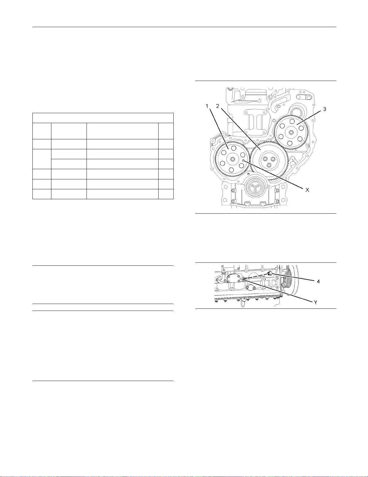
1. Use Tooling (A) in order to rotate the crankshaft
so that number o
ne piston is at top dead center
on the compression stroke. Refer to Testing and
Adjusting Manual, “Finding Top Centre Position for
No.1 Piston”.
Illustration 32
g01194629
2. Install Tooling (B) through the hole (X) in the
camshaft gear (1) into the front housing. Use
Tooling (B) in order to lock the camshaft in the
correct position.
NOTICE
Keep all parts clean from contaminants.
Contaminants may cause rapid wear and shortened
component life.
NOTICE
Care must be taken to ensure that fluids are contained
during performance of inspection, maintenance, testing, adjusting and repair of the product. Be prepared to
collect the fluid with suitable containers before opening any compartment or disassembling any component containing fluids.
Dispose of all fluids according to local regulations and
mandates.
Note: Care must be taken in order to ensure that
the fuel injection pump timing is not lost during the
removal of the fuel pump gear. Carefully follow the
procedure in order to remove the fuel pump gear.
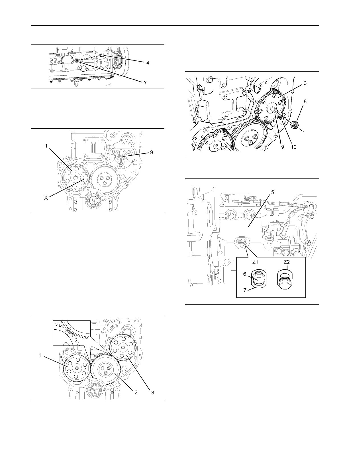
Illustration 33
g01195325
3. Remove the plug (4) from the cylinder block. Install
Tooling (C) into the hole (Y) in the cylinder block.
Use Tooling (C) in order to lock the crankshaft in
the correct position.
Note: Do not use excessive force to install Tooling
(C). Do not use Tooling (C) to hold the crankshaft
during repairs.
Page 23
SENR9983 23
Disassembly and Assembly Section
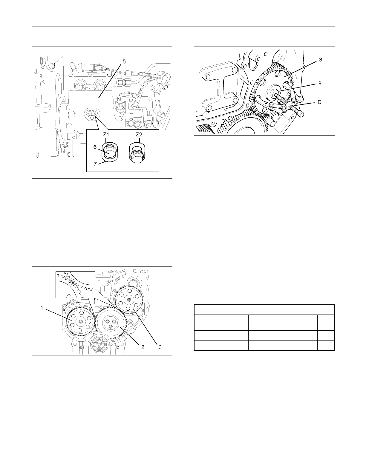
Illustration 34
g01196435
4. Apply sufficient pressure to the fuel injection pump
gear (3) in a counterclockwise direction in order
to remove the backlash. Lock the fuel injection
pump (5) in this position.
In order to lock the fuel injection pump (5), loosen
the locking screw (6) in the fuel injection pump.
Slide the spacer (7) into position (Z). Tighten the
locking screw (6) against the shaft of the fuel
injection pump to a torque of 9 N·m (80 lb in).
Illustration 36
g01196132
6. Loosen the nut (8) for the fuel pump gear (3).
7. Install Tooling (D) through two opposite holes in
the fuel pump gear (3). Tighten Tooling (D) until
the fuel pump gear (3) is released.
8. Remove Tooling (D) from the fuel pump gear (3).
9. Remove the nut (8) and washer (not shown) from
the fuel pump gear (3). Remove the fuel pump
gear.
i02296767
Fuel Inje ctio n Pump Gear Install
Installation Procedure
Table 6
Required Tools
Too l
B
C
Part
Number
27610212
27610286
Part Name Qty
Camshaft Timing Pin 1
Crankshaft Timing Pin 1
Illustration 35
Alignment of timing marks
g01196142
5. Mark the gears (1), (2) and (3) in order to show
alignment. Refer to Illustration 35.
Note: Identification will ensure that the gears can be
installed in the original alignment.
NOTICE
Keep all p
arts clean from contaminants.
Contaminants may cause rapid wear and shortened
componen
tlife.
Note: The fuel injection pump must remain locked
until the procedure instructs you to unlock the fuel
injection pump.
1. Ensure that number one piston is at top dead
center on the compression stroke. Refer to the
Testing and Adjusting Manual, “Finding Top Center
for No. 1 Piston”.
Page 24
24 SENR9983
Disassembly and Assembly Section
7. Install the fuel pump gear (3) to the shaft (9) of the
fuel injection
pump. Ensure that the timing marks
on the gears (2) and (3) are in alignment and that
the mesh of the gears is correct.
Illustration 37
g01195325
2. Ensure that Tooling (C) is installed in hole (Y) in
the cylinder block. Use Tooling (C) in order to lock
the crankshaft in the correct position.
Illustration 38
g01196475
3. Ensure that Tooling (B) is installed into the hole
(X) in the camshaft gear (1).
4. Ensure that the shaft (9) of the fuel injection pump
is clean and free from damage.
Illustration 40
Typical example
g01196488
5. Ensure that the fuel injection pump is locked in
the correct position. Refer to Disassembly and
Assembly Manual, “Fuel Injection Pump - Install”.
6. Ensure that the fuel pump gear is clean and free
from wear of damage. If necessary, replace the
fuel pump gear.
Illustration 39
Alignment of timing marks
g01194949
Illustration 41
g01196435
8. Install a new spring washer (10) and install the
nut (8) to the shaft (9) of the fuel injection pump.
Apply sufficient pressure to the fuel injection
pump gear (3) in a counterclockwise direction in
order to remove the backlash. Tighten the nut (8)
toatorqueof25N·m(18lbft).Unlockthefuel
injection pump (5).
In order to unlock the fuel injection pump (5),
loosen the locking screw (5) in the fuel injection
pump. Slide the spacer (7) into position (Z1).
Tighten the locking screw (6) against the spacer to
a torque of 9 N·m (80 lb in). This will prevent the
locking screw from tightening against the shaft of
the fuel injection pump.
Page 25
SENR9983 25
Disassembly and Assembly Section
9. RemoveTooling(B)and(C).Installtheplug
(4) into hole (Y
Illustration 37.
10. Tighten the nu
(66.4lbft).
) in the cylinder block. Refer to
t(8)toatorqueof90N·m
Contact with high pressure fuel may cause fluid
penetration and burn hazards. High pressure fuelspraymaycauseafirehazard.Failuretofollow these inspection, maintenance and service instructions ma y cause personal injury or death.
NOTICE
Ensure that al
l adjustments and repairs that are
carried out to the fuel system are performed by
authorised personnel that have the correct training.
Before begining ANY work on the fuel system, refer to Operati
on and Maintenance Manual, “General Hazard Information and High Pressure Fuel
Lines” for s afety information.
Illustration 42
Checking backlash
g00944084
11. Ensure that the backlash for the gears (2)
and (3) is within specified values. Refer to the
Specifications Manual, “Gear Group (Front)” for
further information.
12. Lubricate the teeth of the gears with clean engine
oil.
End By:
a. Install the front cover. Refer to Disassembly and
Assembly Manual, “Front Cover - Remove and
Install”.
i02295935
Electronic Unit Injec tor Remove
Removal Procedure (One Injector)
Table 7
Required Tools
Tool Part Number Part Description Qty
21825576
A
B
C
-
27610288
Start By:
a. Remove the valve mechanism cover. Refer
to Disassembly and Assembly Manual, “Valve
Mechanism Cover - Remove and Install”.
Engine Turning Tool 1
T40 T orx Socket
Pry Bar 1
1
Refer to Testing and Adjusting Manual, “Cleanliness of Fuel System Components” for detailed
informatio
n on the standards of cleanliness that
must be observed during ALL work on the fuel
system.
1. Isolate the fuel supply to the engine.
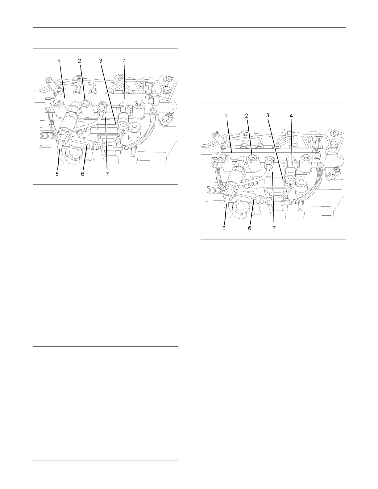
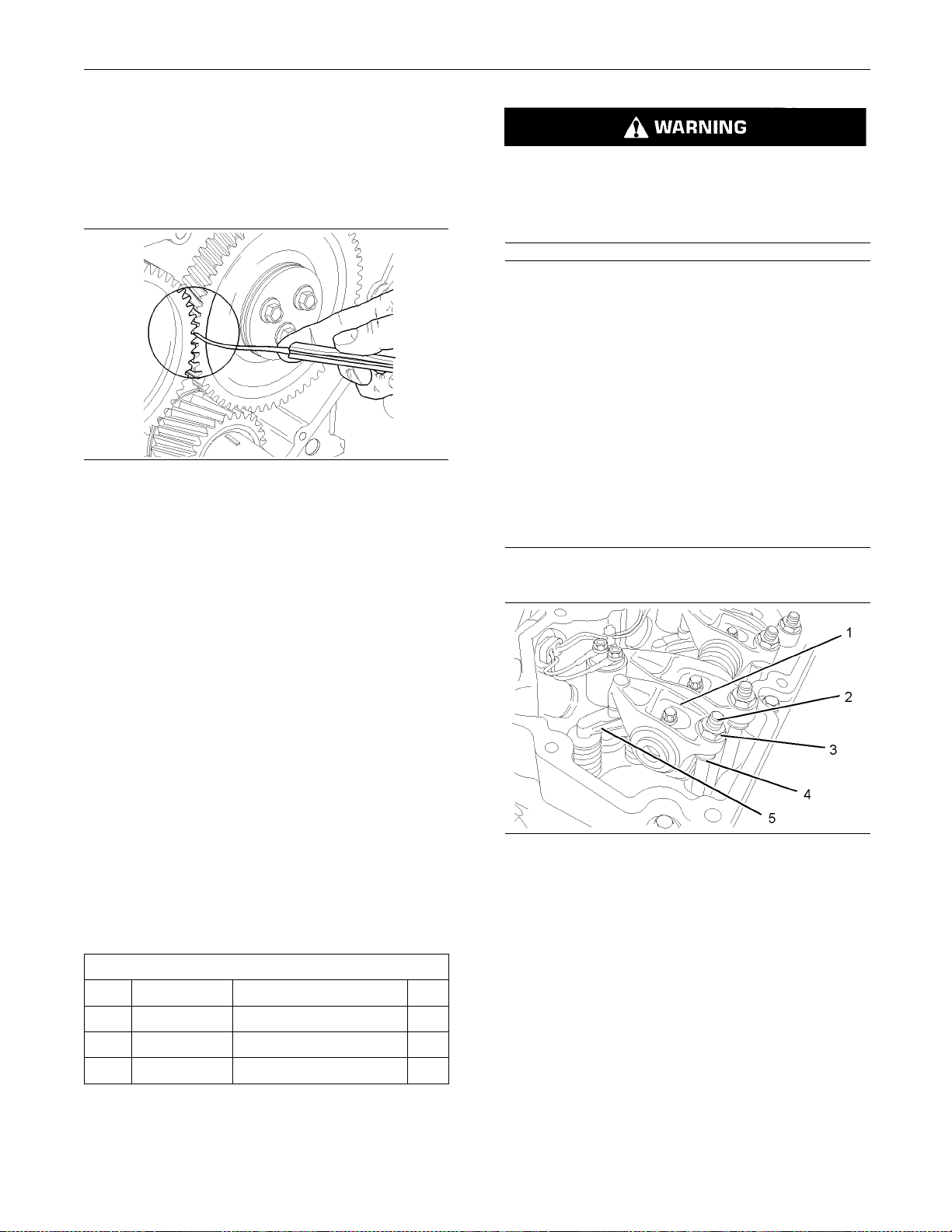
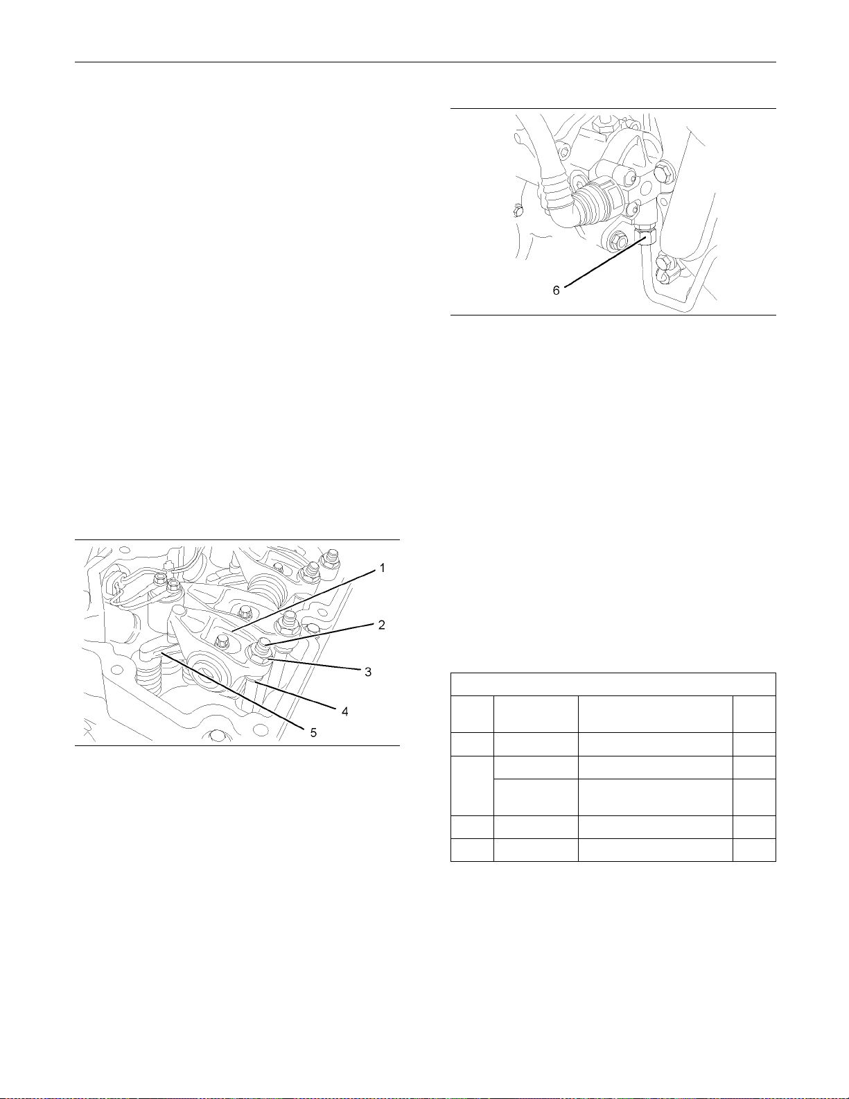
Illustration 43
Typical example
g01193285
2. Use Tooling (A) in order to rotate the crankshaft
until the rocker arms (1) for the appropriate
cylinder are in the correct position in order to adjust
the valve lash. Refer to Testing and Adjusting
Manual, “Engine Valve Lash - Inspect/Adjust”.
3. Follow Steps 3.a through 3.c in order to gain
access to the assembly of the electronic unit
injector.
a. Loosen the nuts (3) on the appropriate cylinder.
Unscrew the adjusters (2) on the appropriate
cylinder until the pushrods (4) can be withdrawn
from the balls of the adjusters.
b. Withdraw the cups of the pushrods (4) from the
balls of the adjusters (2).
Page 26
26 SENR9983
Disassembly and Assembly Section
c. Make a temporary mark on the valve bridges
(5) in order to s
how the location and orientation.
Remove valve bridges from the cylinder head.
Note: Identif
ication will ensure that the valve bridges
can be reinstalled in the original location and the
original orientation. Do not interchange the location
or the orient
ation of used valve bridges.
4. Place a suitable container below the fuel transfer
pump in order
to catch any fuel that might be
spilled.
Note: Clean u
p any spillage of fuel immediately.
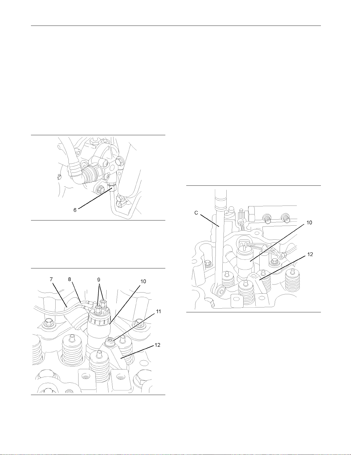
6. Remove the fuel injection line (not shown) and
the seal (7) fro
m the appropriate electronic unit
injector (10). Refer to Disassembly and Assembly
Manual, “Fuel Injecton Lines - Remove”.
Note: Cap all open ports immediately with new caps.
7. Place a tempor
ary identification mark on the
connections (9) for the harness assembly (8).
8. Use a deep sock
et to remove the connections (9)
from the electronic unit injectors (10).
9. Slide the roc
ker arms (1) to one side in order to
gain access to the torx screw (11). Use Tooling (B)
in order to remove the torx screw from the clamp
(12). Discar
d the t orx screw.
10. Place a temporary identification mark on the
electronic u
nit injector (10). The electronic unit
injector must be reinstalled in the original location
in the cylinder head.
Illustration 44
Typical exam p le
g01193839
5. Disconnect the tube assembly (6) for the injector
leak-off from the fuel transfer pump. Allow the fuel
to drain from the tube assembly.
Illustration 46
The rocker shaft is not shown for clarity.
g01193295
11. Use Tooling (C) to pry beneath the clamp (12)
and free the electronic unit injector (10) from the
cylinder head.
12. Remove the electronic unit injector (10) and the
clamp (12) from the cylinder head.
Illustration 45
The rocker shaft is not shown for clarity.
g01193293
Page 27
SENR9983 27
Disassembly and Assembly Section
NOTICE
Ensure that all adjustments and repairs that are
carried out to t
he fuel system are performed by
authorised personnel that have the correct training.
Before begining ANY work on the fuel system, refer to Operation and Maintenance Manual, “General Hazard In
formation and High Pressure Fuel
Lines” for s afety information.
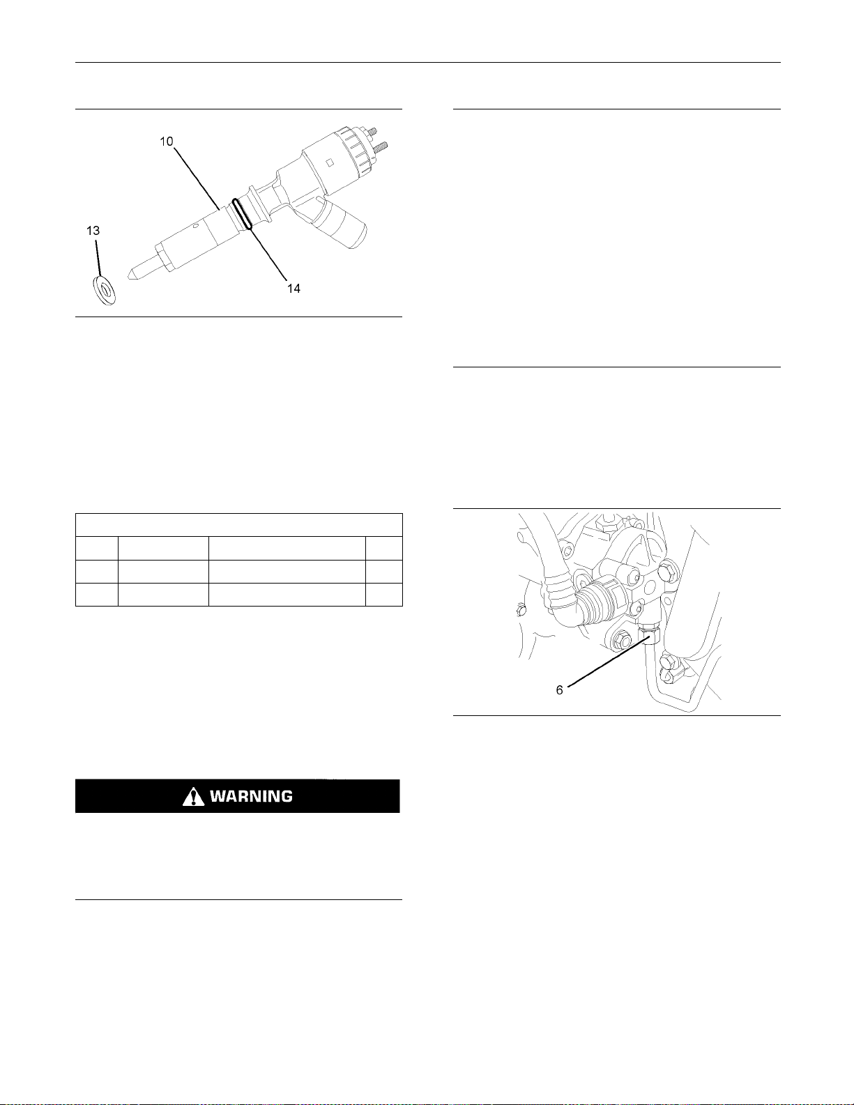
Illustration 47
g01193297
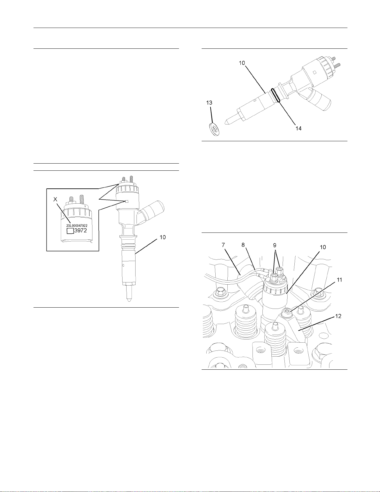
13. Remove the sealing washer (13) from the base of
the electronic unit injector (10) or from the bore in
the cylinder head. Discard the sealing washer.
14. Remove the O-ring seal (14) from the electronic
unit injector (10). Discard the O-ring seal.
Removal Procedure (All Injectors)
Table 8
Required Tools
Tool Part Number Part Description Qty
B
C
-
27610288
T40 T orx Socket
Pry Bar 1
Start By:
a. Remove the rocker shaft assembly. Refer to
Disassembly and Assembly Manual, “Rocker
Shaft - Remove”.
1
Refer to Testi
ng and Adjusting Manual, “Cleanliness of Fuel System Components” for detailed
information on the standards of cleanline ss that
must be obser
ved during ALL work on the fuel
system.
1. Isolate the f
uel supply to the engine.
2. Place a suitable container below the fuel transfer
pumpinorde
r to catch any fuel that might be
spilled.
Note: Clean
up any spillage of fuel immediately.
b. Remove the fuel injection lines. Refer to
Disassembly and Assembly Manual, “Fuel
Injecton Lines - Remove”.
Contact with high pressure fuel may cause fluid
penetration and burn hazards. High pressure fuel spray may cause a fire hazard. Failure to follow these inspection, maintenance and service instructions may cause personal injury or death.
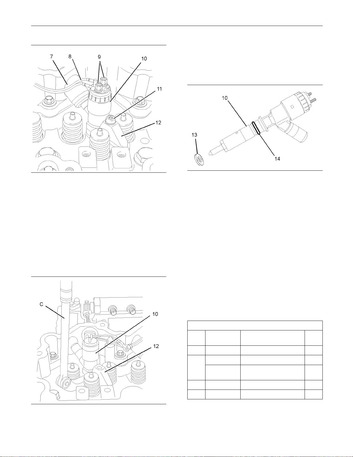
Illustration 48
Typical example
g01193839
3. Disconnect the tube assembly (6) for the injector
leak-off from the fuel transfer pump. Allow the fuel
to drain from the tube assembly.
Page 28
28 SENR9983
Disassembly and Assembly Section
8. Use Tooling (C) to pry beneath the clamp (12)
and free the ele
ctronic unit injector (8) from the
cylinder head.
Illustration 49
g01193293
4. Place a temporary identification mark on the
connections (9) for the harness assembly (8).
5. Use a deep socket to remove the connections (9)
from the electronic unit injectors (10).
6. Use Tooling (B) in order to remove the torx screw
(11) from the clamp (12). Discard the torx screw.
7. Place a temporary identification mark on the
electronic unit injector (10). The electronic unit
injector must be reinstalled in the original location
in the cylinder head.
9. Remove the ele
ctronic unit injector (10) and the
clamp (12) from the cylinder head.
Illustration 51
g01193297
10. Remove the sealing washer (13) from the base of
the electronic unit injector (10) or from the bore in
the cylinder head. Discard the sealing washer.
11. Remove the O-ring seal (14) from the electronic
unit injector (8). Discard the O-ring seal.
12. Repeat Steps 4 through 11 in order to remove the
remaining electronic unit injectors.
i02295941
Electroni
c Unit Injector - Install
Illustration 50
g01193295
Installation Procedure (One
Injector)
Table 9
Required Tools
Too l Part
B
D
E
F 2761029
Number
-
-
-
27610294
6
Part Description
T40 Torx Socket 1
Vac u um Pum p 1
Tube
7.9 mm (0.31 inch) OD
Injector Pipe Nut Tool 1
Tor q u e W re n ch 1
Qty
1
Page 29
SENR9983 29
Disassembly and Assembly Section
NOTICE
Ensure that all adjustments and repairs that are
carried out to t
he fuel system are performed by
authorised personnel that have the correct training.
Before begining ANY work on the fuel system, refer to Operation and Maintenance Manual, “General Hazard In
formation and High Pressure Fuel
Lines” for safety information.
Refer to Testi
ng and Adjusting Manual, “Cleanliness of Fuel System Components” for detailed
information on the standards of cleanliness that
must be obser
ved during ALL work on the fuel
system.
Illustration 53
g01193297
4. Install a new O-ring seal (14) to the electronic unit
injector (10).
Note: Do not lubricate the O-ring seal.
5. Ensure that the seat for the electronic unit injector
in the cylinder head is clean and free from
damage. Position a new sealing washer (13)
onto the seat for the electronic unit injector in the
cylinder head.
Illustration 52
The location of the calibration code
g01194240
1. If a replacement electronic unit injector is installed,
the calibration code that is located at position (X)
must be programmed into the electronic control
module. Refer to Troubleshooting Guide, “Injector
Trim File” for more information.
2. Use Tooling (D) in order to remove any fuel from
the cylinder.
Note: Evacuate as much fuel as possible from the
cylinder before installing the electronic unit injector.
3. Ensure that the fuel inlet port of the electronic unit
injector is capped. Ensure that the electronic unit
injector is clean.
Illustration 54
The rocker shaft is not shown for clarity.
g01193293
6. Install the clamp (12) to the electronic unit injector
(10). Install the electronic unit injector assembly
into the cylinder head.
Note: Ensure that the electronic unit injector is
pushed firmly against the seat in the cylinder head.
7. Install a new torx screw (11) to the clamp (12).
Tighten the torx screw finger tight.
8. Thoroughly clean the seal (7). Inspect the seal for
damage. If necessary, replace the seal.
Page 30
30 SENR9983
Disassembly and Assembly Section
Note: The seal can be damaged by contact with fuel.
9. Remove the cap from the electronic unit injector
(10). Install the seal (7) to the electronic unit
injector (10)
. Ensure that the flange on the seal is
flush with the valve mechanism cover base.
10. Remove the plu
gs from the new fuel injection line.
Loosely install the fuel injection line (not shown).
Refer to Disassembly and Assembly Manual,
“Fuel Inject
on Lines - Install”.
Note: Ensure that the ends of the fuel injection line
are seated in
the electronic unit injector and the fuel
manifold. Tighten the nuts finger tight.
11. UseTooling(
B) to tighten the torx screw (11) to a
torque of 27 N·m (20 lb ft).
12. Use Tooling (
E) to tighten the fuel injection line
(notshown)toatorqueof30N·m(22lbft).Refer
to Disassembly and Assembly Manual, “Fuel
Injecton Li
nes - Install”.
13. Use a deep socket to install the harness assembly
(8) to the el
ectronic unit injector (10). Use Tooling
(F) to tighten the connections to a torque of
2.4N·m(21lbin).
Illustration 56
Typical example
g01193839
16. Connect the tube assembly (6) for the injector
leak-off to the fuel transfer pump.
17. Restore the fuel supply to the engine.
18. Remove the air from the fuel system. Refer to
Operation and Maintenance Manual, “Fuel System
- Prime” for more information.
End By:
a. Install the valve mechanism cover. Refer to
Disassembly and Assembly Manual, “Valve
Mechanism Cover - Remove and Install”.
Installation Procedure (All
Injectors)
Illustration 55
Typical exam p le
g01193285
14. Install bridges (5) to the cylinder head.
Note: Ensure that used valve bridges are reinstalled
in the original location and the original orientation.
Do not interchange the location or the orientation of
used valve bridges.
15. Ensure that the bottoms of the pushrod are
seated in the cups of the valve lifters. Locate
the balls of the adjusters (2) into the cups of the
pushrods (4). Adjust the valve lash. Refer to
Testing and Adjusting Manual, “Engine Valve Lash
- Inspect/Adjust”.
Table 10
Too l Part
B
D
E
F
Number
27610294
27610296
Required Tools
-
-
-
Part Descr
T40 Torx Socket
Vac u um Pum p 1
Tube
7.9 mm (0.31 inch) OD
Injector Pipe Nut Tool 1
Tor q ue W r en ch 1
iption
Qty
1
1
Page 31

SENR9983 31
Disassembly and Assembly Section
NOTICE
Ensure that all adjustments and repairs that are
carried out to t
he fuel system are performed by
authorised personnel that have the correct training.
Before begining ANY work on the fuel system, refer to Operation and Maintenance Manual, “General Hazard In
formation and High Pressure Fuel
Lines” for safety information.
Refer to Testi
ng and Adjusting Manual, “Cleanliness of Fuel System Components” for detailed
information on the standards of cleanliness that
must be obser
ved during ALL work on the fuel
system.
Illustration 58
g01193297
4. Install a new O-ring seal (14) to the electronic unit
injector (10).
Note: Do not lubricate the O-ring seal.
5. Ensure that the seat for the electronic unit injector
in the cylinder head is clean and free from
damage. Position a new sealing washer (13)
on the seat for the electronic unit injector in the
cylinder head.
Illustration 57
The location of the calibration code
g01194240
1. If a replacement electronic unit injector is installed,
the calibration code that is located at position (X)
must be programmed into the electronic control
module. Refer to Troubleshooting Guide, “Injector
Trim File” for more information.
2. Use Tooling (D) to remove any fuel from the
cylinder.
Note: Evacuate as much fuel as possible from the
cylinder before installing the electronic unit injector.
3. Ensure that the fuel inlet port of the electronic unit
injector is capped. Ensure that the electronic unit
injector is clean.
Illustration 59
g01193293
6. Install the clamp (12) to the electronic unit injector
(10). Install the electronic unit injector assembly
into the original location in the cylinder head.
Note: Ensure that the electronic unit injector is
pushed firmly against the seat in the cylinder head.
7. Install a new torx screw (11) to the clamp (12).
Tighten the torx screw finger tight.
8. Thoroughly clean the seal (7). Inspect the seal for
damage. If necessary, replace the seal.
Page 32

32 SENR9983
Disassembly and Assembly Section
Note: The seal can be damaged by contact with fuel.
9. Remove the cap from the electronic unit injector
(10). Install the seal (7) to the electronic unit
injector (10)
flush with the valve mechanism cover base.
10. Remove the plu
Loosely install the fuel injection line (not shown).
Refer to Disassembly and Assembly Manual,
“Fuel Inject
Note: Ensure that the ends of the fuel injection line
are seated in
manifold. Tighten the nuts finger tight.
11. UseTooling(
torque of 27 N·m (20 lb ft).
12. Use Tooling (
(notshown)toatorqueof30N·m(22lbft).Refer
to Disassembly and Assembly Manual, “Fuel
Injecton Li
13. Use a deep socket to install the harness assembly
(8) to the el
(F) to tighten the connections to a torque of
2.4N·m(21lbin).
14. Repeat Steps 2 through 13 in order to install the
remaining electronic unit injectors.
. Ensure that the flange on the seal is
gs from the new fuel injection line.
on Lines - Install”.
the electronic unit injector and the fuel
B) to tighten the torx screw (11) to a
E) to tighten the fuel injection line
nes - Install”.
ectronic unit injector (10). Use Tooling
i02295944
Turbocharger - R emo v e
Removal Proced
Turbochargers)
Keep all parts clean from contaminants.
Contaminants
component life.
Care must be taken to ensure that fluids are contained
during performance of inspection, maintenance, testing, adjustin
collect the fluid with suitable containers before opening any compartment or disassembling any component contain
Dispose of all fluids according to local regulations and
mandates.
1. Disconnect the air hose for the turbocharger inlet
and for the turbocharger outlet (not shown). Refer
to OEM inform
may cause rapid wear and shortened
g and repair of t he product. Be prepared to
ing fluids.
ation for the correct procedure.
ure (Side Mounted
NOTICE
NOTICE
15. Install the rocker shaft assembly. Refer to
Disassembly and Assembly, “Rocker Shaft Install”.
Illustration 60
Typical exam p le
16. Connect the tube assembly (6) for the injector
leak-off to the fuel transfer pump.
17. Restore the fuel supply to the engine.
18. Remove the air from the fuel system. Refer to
Operation and Maintenance Manual, “Fuel System
-Prime”formoreinformation.
g01193839
2. If the turbocharger has a remote wastegate
solenoid, di
shown) from the turbocharger.
3. Disconnect
OEM information for the correct procedure.
4. If the turbo
remove the exhaust elbow (not shown). Refer to
Disassembly and Assembly Manual, “Exhaust
Elbow - Rem
sconnect the hose to the solenoid (not
the exhaust pipe (not shown). Refer to
charger has an exhaust elbow,
ove and Install”.
Page 33

SENR9983 33
Disassembly and Assembly Section
Illustration 61
g01165546
5. Follow Steps 5.a through 5.c in order to remove
the tube assembly (4) for the oil feed.
a. Remove the setscrew (5).
b. Remove the banjo bolt (1) and remove the
two sealing washers (2). Discard the sealing
washers.
c. Remove the tube assembly (3) from the
cylinder block. Remove the O-ring seal (4) from
the t ube assembly. Discard the O-ring seal.
Note: Plug the port for the oil feed to the turbocharger
withasuitableplug.
6. Follow Steps 6 through 6.c in order to remove the
tube assembly (10) for the oil drain.
Illustrat
ion 62
g01171991
7. Remove the four nuts (15) from the turbocharger
(6) and re
move the turbocharger (6) from the
exhaust manifold (12).
Note: Ens
ure that the weight of the turbocharger is
supported as the nuts are loosened.
8. Remove th
e joint (14). Discard the joint.
9. If necessary, rem ove the four studs (13) from the
exhaust m
Removal P
anifold (12).
rocedure (Top Mounted
Turbochargers)
NOTICE
Keep all parts clean from contaminants.
Contami
component life.
nants may cause rapid wear and shortened
a. Remove the two setscrews (11).
b. Remove the two setscrews (8) and remove the
tube assembly (10) from the turbocharger (6).
c. Remove the joint (7) and remove the joint (9).
Discard the joints.
Page 34

34 SENR9983
Disassembly and Assembly Section
6. Remove the setscrew (8) in order to disconnect
NOTICE
thetubeassemb
ly (7) from the cylinder block.
Care must be taken to ensure that fluids are contained
during perform
ance of inspection, maintenance, test-
7. Remove the fasteners for the tube clips (2).
ing, adjusting and repair of the product. Be prepared to
collect the fluid with suitable containers before opening any compar
tment or disassembling any compo-
nent containing fluids.
8. Loosen the four nuts (11). Refer to Illustration 64.
9. Remove the exh
aust manifold (1) and the
assembly of the turbocharger from the cylinder
Dispose of all
mandates.
fluids according to local regulations and
head. Refer to Disassembly and Assembly
Manual, “Exha
ust Manifold - Remove and Install”
for the correct procedure.
1. Disconnect the air hose for the turbocharger inlet
andforthetur
bocharger outlet (not shown). Refer
to OEM information for the correct procedure.
2. If the turboc
harger has a remote wastegate
solenoid, disconnect the hose to the solenoid (not
shown) from the turbocharger.
3. Disconnect the exhaust pipe (not shown). Refer to
OEM information for the correct procedure.
4. If the turbocharger has an exhaust elbow,
remove the exhaust elbow (not shown). Refer to
Disassembl
y and Assembly Manual, “Exhaust
Elbow - Remove and Install”.
ration 63
Illust
5. Remove the two setscrews (5) in order to
nect the tube assembly (4) from the cylinder
discon
block. Remove the joint (3). Discard the joint.
g01183875
Illustration 64
g01185011
10. Remove the banjo bolt (9) and remove the tube
assembly (7) for the oil feed from the turbocharger
(12). Remove the two sealing washers (10).
Discard t he sealing washers.
Note: Plug the port for the oil feed to the turbocharger
with a suitable plug.
11. RemovetheO-ringseal(6)fromthetube
assembly (7). Refer to Illustration 63. Discard the
O-ring seal.
Page 35

SENR9983 35
Disassembly and Assembly Section
12. Remove the two setscrews (14) and remove
thetubeassemb
turbocharger (12).
13. Remove the joi
14. Remove the four nuts (11) and remove the
turbocharger
ly (4) for the oil drain from the
nt (13). Discard the joint.
(12) from the exhaust manifold (1).
NOTICE
Do not attempt to disassemble the turbocharger
cartridge asse
the compressor wheel. The turbocharger cartridge
assembly and the wastegate are not field serviced,
and should be r
mbly or wastegate. Do not remove
eplaced only as a unit.
Note: Ensure that the exhaust manifold and the
turbocharger
removal of the turbocharger.
15. Remove the jo
(1). Discard the joint.
16. If necessary
exhaust manifold (1).
are adequately supported during the
int (15) from the exhaust manifold
, remove the four studs (16) from the
i02347778
Turbocharger - Disassemble
Disassembly Procedure
NOTICE
Keep all parts clean from contaminants.
Contaminants may cause rapid wear and shortened
component life.
Turbocharger
- Assemble
Assembly Procedure
NOTICE
Keep all parts clean from contaminants.
Contaminants
component life.
may cause rapid wear and shortened
i02347770
Illustration 65
1. Disconne
the actuator (6).
2. Remove th
rod (4).
3. Remove th
4. Remove the nuts (5) from the bracket (3).
5. Remove the actuator (6) from the bracket (3).
ct the pipe for the boost sensor (7) at
e circlip (1) that retains the actuator
e actuator rod (4) from the pin (2).
g01176032
Illustration 66
1. Install the actuator (6) to the bracket (3). Install the
nuts (5) to the bracket (3).
2. Tighten the nuts to a torque of 5 N·m (44 lb in).
3. Connect the bottom of the actuator (6) to a
suitable air supply with an accurate gauge.
4. Operate the arm of the actuator by hand in order
to check that the valve is free to move.
5. Push the arm of the wastegate valve toward the
actuator (6) and hold the arm in position. Slowly
apply air pressure to the actuator (6) until the pin
(2) will fit into the actuator rod (4). Install the circlip
(1) into the groove in the pin (2).
Note: Do not apply an air pressure of more than
205 kPa (29 psi) to the actuator. High pressures may
damage the actuator.
6. Install the pipe for the boost pressure (7) to the
actuator (6).
g01176032
Page 36

36 SENR9983
Disassembly and Assembly Section
End By:
a. To check the wastegate actuator for correct
operation, refer to Testing and Adjusting,
“Wastegate - I
nspect”.
Turbocharger - Install
Installation Procedure (Side
Mounted Turbochargers)
Table 11
Required Tools
Tool
A
Keep all parts clean from contaminants.
Part
Number
21820221
Part Description Qty
POWERPART
Rubber Grease
NOTICE
i02295957
1
2. Test the wastegate actuator (19) for correct
operation. Ref
er to T esting and Adjusting Manual,
“Turbocharger Inspect”. If the wastegate actuator
is damaged or the wastegate actuator does not
operate withi
n the specified limits, the wastegate
actuator must be replaced. Refer to Disassembly
and Assembly Manual, “Turbocharger Dissassembl
e” and refer to Disassembly and
Assembly Manual, “Turbocharger - Assemble” for
more information.
Contaminants may cause rapid wear and shortened
component life.
ation 67
Illustr
Typical exam p le
g01187836
Illustration 68
example
Typical
g01171991
3. Clean the mating surfaces of the exhaust manifold
(12). If
necessary, install the four studs (13) to the
exhaust manifold. Tighten the studs to a torque of
18 N·m (13 lb ft).
4. Install a new joint (14) to the exhaust manifold
(12).
5. Position the turbocharger (6) on the exhaust
manifold.
Note: Ensure that the turbocharger is correctly
oriented.
1. Ensure that the turbocharger is clean and free
from damage. Inspect the turbocharger for
wear. Re
fer to Testing and Adjusting Manual,
“Turbocharger Inspect” for more information. If
any part of the turbocharger is worn or damaged,
the comp
lete turbocharger must be replaced.
6. Install the four nuts (15). Tighten the nuts to a
torque of 44 N·m (32 lb ft).
Page 37

SENR9983 37
Disassembly and Assembly Section
7. If a new turbocharger is installed, the bearing
housing (18) an
d the compressor housing (20)
must be oriented to the correct positions. Follow
Steps 7.a through 7.d in order to orient the bearing
housing and th
e compressor housing.
a. Loosen the two band clamps (21) sufficiently in
order to allo
w the housings to rotate.
Note: If the band clamps are damaged, replace the
band clamps.
b. Carefully turn the bearing housing (18) until the
port for the o
il feed (17) is upward.
c. Rotate the compressor housing (20) until the
compressor o
utlet is in the correct position.
Refer to the turbocharger that was originally
installed for the correct orientation.
d. Ensure that the band clamps (21) are correctly
oriented. Refer to the turbocharger that was
originally
installed for the correct orientation.
Tighten the band clamps finger tight.
8. Ensure that the tube assemblies (3) and (10)
are clean and fr
ee from damage. Replace any
damaged components.
9. Positionanew
joint (7) and the two setscrews (8)
onto the tube assembly (10).
10. Install the tu
be assembly (10) to the turbocharger
(6). Tighten the setscrews (8) finger tight.
11. Position a new
joint (9) between the flange of the
tube assembly (10) and the cylinder block. Install
the two setscrews (1 1) finger tight.
12. If a new turbocharger has been installed, check
that the orientation of the bearing housing (18) is
correct. If t
he orientation of the bearing housing is
not correct, rotate the bearing housing until the
tube assembly (10) fits correctly. Tighten the two
band clamps
(21) to a torque of 13 N·m (9.6 lb ft).
13. Tighten the setscrews (8) and (1 1) to a torque of
22 N·m (16 lb
ft).
14. Remove the plug from the oil inlet port (17).
Lubricate t
he turbocharger bearings with clean
engine oil through the oil inlet port. Rotate the
wheel of the compressor several times in order to
lubricate
the bearings.
Illustration 69
g01165546
15. Use Tooling (A) in order to lubricate a new O-ring
seal (4). I
nstall the O-ring seal (4) to the tube
assembly (3).
16. Install th
e banjo bolt (1) and two new sealing
washers (2) to the tube assembly (3).
17. Install t
he tube assembly (3) to the cylinder block
and to the turbocharger (6). Tighten the banjo bolt
(1)fingertight.
18. Install the setscrew (5) finger tight. Ensure that
the tube assembly (3) fits correctly.
19. Tighten the banjo bolt (1) to a torque of 20 N·m
(14 lb ft). Tighten the setscrew (5) and (11) to a
torque of
22 N·m (16 lb ft).
20. If the turbocharger has an exhaust elbow, install
the exhau
st elbow. Refer to Disassembly and
Assembly Manual, “Exhaust Elbow - Remove and
Install”.
21. Connect the exhaust pipe (not shown). Refer to
OEM information for the correct procedure.
22. If the turbocharger has a remote wastegate
solenoid, connect the hose for the solenoid (not
shown) t
o the turbocharger.
23. Connect the air inlet hose and connect the air
hose (not shown) to the turbocharger. Refer
outlet
to OEM information for the correct procedure.
Page 38

38 SENR9983
Disassembly and Assembly Section
Installation Procedure (Top
Mounted Turbochargers)
Table 12
Required Tools
Tool
A 218200221
Part
Number
Part Descript
POWERPART
Rubber Grease
NOTICE
Keep all parts clean from contaminants.
Contaminants may cause rapid wear and shortened
component life.
ion
Qty
1
Illustration 70
Typical e
xample
g01187836
1. Ensure that the turbocharger is clean and free
from dama
ge. Inspect the turbocharger for
wear. Refer to Testing and Adjusting Manual,
“Turbocharger Inspect” for more information. If the
turbocha
rger is worn, the complete turbocharger
must be replaced.
2. Te st th e
wastegate actuator (19) for correct
operation. Refer to T esting and Adjusting Manual,
“Turbocharger Inspect”. If the wastegate actuator
is damag
ed or the wastegate actuator does not
operate within the specified limits, the wastegate
actuator must be replaced. Refer to Disassembly
and Ass
embly Manual, “Turbocharger Dissassemble” and refer to Disassembly and
Assembly Manual, “Turbocharger - Assemble” for
more in
formation.
Illustration 71
g01185011
3. Clean the mating surfaces of the exhaust manifold
(1). If necessary, install the four studs (16) to the
exhaust manifold. Tighten the studs to a torque of
18 N·m (13 lb ft).
Note: Support the exhaust manifold during
installation of the turbocharger.
4. Install a new joint (15) to the exhaust manifold (1).
5. Position the turbocharger (12) on the exhaust
manifold (1).
Note: Ensure that the turbocharger is correctly
oriented.
6. Install the four nuts (11). Tighten the nuts to a
torque of 44 N·m (32 lb ft).
Page 39

SENR9983 39
Disassembly and Assembly Section
7. If a new turbocharger is installed, the bearing
housing (18) an
d the compressor housing (20)
must be oriented to the correct positions. Refer
to Illustration 70. Follow Steps 7.a through 7.d
in order to ori
ent the bearing housing and the
compressor housing.
a. Loosen the tw
o band clamps (21) sufficiently in
order to allow the housings to rotate.
Note: If the b
and clamps are damaged, replace the
band clamps.
b. Carefully tu
rn the bearing housing (18) until the
port for the oil feed (17) is upward.
c. Rotate the co
mpressor housing (20) until the
compressor outlet is in the correct position.
Refer to the turbocharger that was originally
installed f
or the correct orientation.
d. Ensure that the band clamps (21) are correctly
oriented. R
efer to the turbocharger that was
originally installed for the correct orientation.
Tighten the band clamps finger tight.
8. Ensure that the tube assemblies (4) and (7)
are clean and free from damage. Replace any
damaged co
mponents.
9. Position a new joint (13) and the two setscrews
(14) onto t
he tube assembly (4).
10. Install the tube assembly (4) to the turbocharger
(12). Tigh
ten the setscrews (14) finger tight.
Illustrat
ion 72
g01183875
15. Install the exhaust manifold (1) and the assembly
of the tur
bocharger to the cylinder head. Refer
to Disassembly and Assembly Manual, “Exhaust
Manifold - Remove and Install” for the correct
procedur
e.
11. Remove the plug from the oil inlet port (17).
Refer to I
llustration 70. Lubricate the turbocharger
bearings with clean engine oil through the oil inlet
port. Rotate the wheel of the compressor several
times in o
rder to lubricate the bearings.
12. Install the banjo bolt (9) and two new sealing
washers (
10) to the tube assembly (7).
13. Use Tooling (A) in order to lubricate a new O-ring
seal (6).
Install the O-ring seal (6) to the tube
assembly (7). Refer to Illustration 72.
14. Install t
he tube assembly (7) to the turbocharger
(12). Tighten the banjo bolt (9) finger tight.
16. Install the setscrew (8) finger tight. Ensure that
the tube
assembly (7) fits correctly.
17. Position a new joint (3) between the flange of the
tube ass
embly (4) and the cylinder block. Install
the two setscrews (5) finger tight.
18. If a new t
urbocharger has been installed, check
that the orientation of the bearing housing (18) is
correct. If the orientation of the bearing housing is
not corr
ect, rotate the bearing housing until the
tube assemblies (4) and (7) fit correctly. Tighten
the two band clamps (21) to a torque of 13 N·m
(9.6 lb
ft).
19. Tighten the banjo bolt (9) to a torque of 20 N·m
(14lbf
t). Tighten the setscrew (5) and (8) to a
torque of 22 N·m (16 lb ft).
20. Instal
l the fasteners for the tube clips (2) to the
cylinder block.
21. If the t
urbocharger has an exhaust elbow, install
the exhaust elbow. Refer to Disassembly and
Assembly Manual, “Exhaust Elbow - Remove and
ll”.
Insta
Page 40

40 SENR9983
Disassembly and Assembly Section
22. Connect the exhaust pipe (not shown). Refer to
OEM informatio
23. If the turbocharger has a remote wastegate
solenoid, con
shown) to the turbocharger.
24. Connect the ai
outlet hose (not shown) to the turbocharger. Refer
to OEM information for the correct procedure.
n for the correct procedure.
nect the hose for the solenoid (not
r inlet hose and connect the air
i02347765
Wastegate Solenoid - Remove
and Install
Removal Procedure
Note: Thetubeclipsmustbelooseinordertorelease
thetubeassemb
4. Remove the two setscrews (5) and remove the
wastegate sol
5. Plug or cap all open ports and tube assemblies
with new plugs
Installation
1. Remove the plugs or caps from all ports and tube
assemblies.
ly from the wastegate solenoid.
enoid (3) from the cylinder block.
or caps.
Procedure
Illustration 73
Typical exam p le
1. Follow Steps 1.a through 1.c in order to disconnect
thewirelead(1).
a. Disconnect the wire lead (1) from the harness
assembly (not shown).
b. If the harness assembly (1) is secured with a
cable tie, remove the cable tie.
c. Remove the wire lead (1) from the tube
assembly (2).
Note: The wire lead is secured to the tube assembly
with clips.
2. Disconnect the tube assembly (2) from the
wastegate solenoid (3).
3. Disconnect the tube assembly (4) from the
wastegate solenoid (3). If the tube assembly (4)
is secured with tube clips, loosen the fasteners
for the tube clips.
g01165640
Illustration 74
Typical example
2. Loosely install the wastegate solenoid (3) to the
tube assembly (2).
3. Loosely install the tube assembly (4) to the
wastegate solenoid (3).
4. Install the two setscrews (5) to the wastegate
solenoid (3). Tighten the setscrews (5) to a torque
of 44 N·m (32.5 lb ft).
5. Tighten tube assemblies (2) and (4) to a torque of
22 N·m (16 lb ft).
6. If the tube assembly (4) is secured with tube clips,
tighten the fasteners for the tube clips.
Tighten M8 fasteners to a torque of 22 N·m
(16 lb ft). Tighten M10 fasteners to a torque of
44 N·m (32.5 lb ft).
7. Follow Steps 7 through 7.c in order to connect the
wire lead (1).
a. Install the wire lead (1) to the tube assembly
(2).
b. Connect the wire lead (1) to the harness
assembly for the engine (not shown).
g01165640
Page 41

SENR9983 41
Disassembly and Assembly Section
c. Ifthewirelead(1)issecuredwithacabletie,
install a new ca
ble tie.
i02295960
Exhaust Manifo
ld - Rem ove
and Install
Removal Proce
Exhaust Manifold)
Start By:
a. Remove the tur
and Assembly Manual, “Turbocharger - Remove”.
dure (Side Mounted
bocharger. Refer to Disassembly
Illustration 75
Illustration 7 6
1. Loosen the setscrews (2) and (5) in reverse
numerical order. Refer to Illustration 76.
Note: This will help prevent distortion of the exhaust
manifold.
g01174489
g01176473
2. Remove the center four setscrews (2) from the
exhaust manifold (3). Remove the outer eight
setscrews (5) and the spacers (4) from the
exhaust manifold (3).
Page 42

42 SENR9983
Disassembly and Assembly Section
Note: Support the manifold as the setscrews are
removed.
3. Remove the exhaust manifold (3).
4. Remove the two exhaust manifold gaskets (1).
Discard the gaskets.
5. If necessary, remove the four studs (6) from the
exhaust manifold (3).
Removal Procedure (Top Mounted
Exhaust Manifold)
1. Disconnect al
l hoses, tube assemblies and wire
leads from the turbocharger. Refer to Disassembly
and Assembly Manual, “Turbocharger - Remove”
Steps 1 throu
Illustration 77
gh 7.
g01176186
Illustration 78
2. Loosen the setscrews (2) and (5) in reverse
numerical order. Refer to Illustration 78.
g01176487
Note: This will help prevent distortion of the exhaust
manifold.
Page 43

SENR9983 43
Disassembly and Assembly Section
3. Remove the center four setscrews (2) from the
exhaust manifo
ld (3). Remove the outer eight
setscrews (5) and the spacers (4) from the
exhaust manifold (3).
Note: Support the manifold as the setscrews are
removed.
4. Remove the assembly of the exhaust manifold
(3) and the turbocharger.
5. Remove the two exhaust manifold gaskets (1).
Discard the gaskets.
6. Remove the turbocharger from the exhaust
manifold (3). Refer to Disassembly and Assembly
Manual, “Tur
bocharger - Remove” Steps 8 through
15.
7. If necessary
, remove the four studs (6) from the
exhaust manifold (3).
Installation Procedure (Side
Mounted Exh
Table 13
Too l
A
B
Part
Number
aust Man ifold)
Required Tools
Part Description Qty
-
-
Guide Stud
(M10 by 100 mm)
Loctite 575
4
-
Illustration 79
g01176473
Page 44

44 SENR9983
Disassembly and Assembly Section
End By:
a. Install the turbocharger. Refer to Disassembly and
Assembly, “Turbocharger - Install”.
Installation Procedure (Top
Mounted Exhaust Manifold)
Table 14
Required Tools
Tool
A
B
Part
Number
-
-
Part Description Qty
Guide Stud
(M10 by 100 mm)
Loctite 575
4
-
Illustration 80
g01174489
1. Ensure that the exhaust manifold is clean and free
from damage. If necessary, replace the exhaust
manifold. Clean the joint face of the cylinder head.
2. If necessary, install the four studs (6) to the
exhaust manifold (3). Tighten the studs to a torque
of 18 N·m (13 lb ft).
3. Install Tooling (A) to the cylinder head in the
positions (X). Refer to Illustration 79.
4. Position two new exhaust manifold gaskets (1)
onto Tooling (A).
Note: Ensure that the word TOP is outward and
upward.
5. Align the exhaust manifold (3) with Tooling (A).
Install the exhaust manifold to the cylinder head.
6. If the setscrews (2) and (5) have been previously
used, the setscrews should be thoroughly cleaned.
Tooling (B) should be applied to the first two
threads of the setscrews.
Note: Do not apply Tooling (B) to new setscrews.
7. Install the setscrews (2) finger tight. Install the
setscrews (5) and the spacers (4) finger tight.
8. Remove Tooling (A). Install the remaining
setscrews (2) finger tight. Install the remaining
setscrews (5) and spacers (4) finger tight.
9. Tighten the setscrews (2) and (5) to a torque of
44 N·m (32 lb ft). Tighten the setscrews in the
sequence that is shown in Illustration 79.
Page 45

SENR9983 45
Disassembly and Assembly Section
Illustration 8 1
Illustration 82
1. Ensure that the exhaust manifold is clean and free
from damage. If necessary, replace the exhaust
manifold. Clean the joint face of the cylinder head.
g01176186
g01176487
7. If the setscrews (2) and (5) have been previously
used, the setscrews should be thoroughly cleaned.
Tooling (B) should be applied to the first two
threads of the setscrews.
Note: Do not apply Tooling (B) to new setscrews.
8. Install the setscrews (2) finger tight. Install the
setscrews (5) and the spacers (4) finger tight.
9. Remove Tooling (A). Install the remaining
setscrews (2) finger tight. Install the remaining
setscrews (5) and spacers (4) finger tight.
10. Tighten the setscrews (2) and (5) to a torque of
44 N·m (32 lb ft). Tighten the setscrews in the
sequence that is shown in Illustration 81.
11. Connect all hoses, tube assemblies and wire
leads from the turbocharger. Refer to Disassembly
and Assembly, “Turbocharger - Install” Steps 16
through 24.
i02296079
Exhaust Elbow - R emove and
2. If necessary, install the four studs (6) to the
exhaust manifold (3). Tighten the studs to a torque
of 18 N·m (13 lb ft).
3. Install the turbocharger to the exhaust
manifold. Refer to Disassembly and Assembly,
“Turbocharger - Install” Steps 1 through 14.
4. Install Tooling (A) to the cylinder head in the
positions (X). Refer to Illustration 81.
5. Position two new exhaust manifold gaskets (1)
onto Tooling (A).
Note: Ensure that the word TOP is outward and
upward.
6. Align the exhaust manifold (3) with Tooling (A).
Install the exhaust manifold to the cylinder head.
Install
Removal Procedure
Start By
a. Remove the exhaust pipe. Refer to OEM
:
informa
remove the exhaust pipe.
tion for the correct procedure in order to
Page 46

46 SENR9983
Disassembly and Assembly Section
4. Some types of exhaust elbow have a separate
support bracke
t. If necessary, install the bracket
and install the setscrews that secure the bracket
to the exhaust elbow finger tight.
5. Install setscrews (1) finger tight.
Illustration 83
Typical exam p le
g01163679
1. Remove the setscrews (1) that secure the exhaust
elbow (2) to the engine. Remove the exhaust
elbow (2) from the engine.
2. Remove the coupling (4) that connects exhaust
elbow (2) to the turbocharger (3).
3. Some types of exhaust elbow have a separate
support bracket. If necessary, remove the
setscrews that secure the bracket to the exhaust
elbow. Remove the support bracket.
Installation Procedure
6. Ensure that th
e coupling (4) is fully engaged into
the outlet of the turbocharger (3) and into the
exhaust elbow (2). Ensure that the gap between
the turbocha
rger and the exhaust elbow is evenly
spaced.
7. Tighten the s
etscrews (1) to a torque of 44 N·m
(33 lb ft).
8. If the exhaus
t elbow has a separate support
bracket, tighten the setscrews that secure the
bracket to the exhaust elbow to a torque of 44 N·m
(33 lb ft).
End By:
a. Install the exhaust pipe. Refer to OEM information
for the correct procedure in order to install the
exhaust pip
e.
i02352176
Inlet Manifold - Re move and
Install
tion 84
Illustra
Typical exam p le
g01163679
1. Thoroughly clean the exhaust elbow (2), the
coupling (4) and the outlet of the turbocharger (3).
Inspect t
he sealing faces of the components for
wear or damage. Replace any components that
are worn or damaged.
2. Install the coupling (4) to the exhaust elbow (2).
3. Align the
coupling (4) to the outlet of the
turbocharger (3). Install the assembly of the
coupling (4) and the exhaust elbow (2) to the
turboch
arger (3).
Removal Procedure
Start By:
a. If necessa
Disassembly and Assembly Manual, “Fuel Filter
Base - Remove and Install”.
b. Remove the fuel manifold. Refer to Disassembly
and Assembly Manual, “Fuel Manifold - Remove”.
c. Remove the ECM mounting bracket. Refer
to Disassembly and Assembly Manual, “ECM
Mounting
d. Remove the boost pressure sensor. Refer to
Disasse
Pressure Sensor - Remove and Install”.
e. Remove t
to Disassembly and Assembly Manual, “Inlet Air
Temperature Sensor - Remove and Install”.
ry, remove the fuel filter base. Refer to
Bracket - Remove and Install”.
mbly and Assembly Manual, “Boost
he air inlet temperature sensor. Refer
Page 47

SENR9983 47
Disassembly and Assembly Section
8. Do not remove the two dowel pins (7).
NOTICE
Keep all parts clean from contaminants.
Installation Procedure
Contaminants may cause rapid wear and shortened
component life.
1. Disconnect the breather hose from the separator
for the crankcase breather (not shown). Refer to
Disassembly and Assembly Manual, “Crankcase
Breather - Remove”.
Table 15
Required Tools
Too l
A
Part
Number
-
Part Name
3 bond 1368D 1
Qty
NOTICE
Keep all parts
clean from contaminants.
Contaminants may cause rapid wear and shortened
component lif
e.
Illustration 85
g01208825
2. Cut the cable ties that secure the harness
assembly (not shown) to the inlet manifold (4).
Position the harness assembly away from the inlet
manifold.
3. Remove the setscrews (1) from the inlet
connection (2).
4. Remove the inlet connection (2) and the gasket
(3) from the inlet manifold (4). Discard the gasket.
5. Remove the setscrews (5).
6. Remove the inlet manifold (4) from the cylinder
head. Use a suitable tool to pry the inlet manifold
from the cylinder head. Use the recess at position
(X) to pry the inlet manifold.
7. Remove the inlet manifold seal (6) from the recess
in the inlet manifold (4). Discard the seal.
Illustration 86
1. Ensure th
at the inlet manifold is clean and free
g01215536
from damage. If necessary, replace the inlet
manifold. If a new inlet manifold is installed, install
two new d
owel pins (7) to the inlet manifold (4).
Note: Do not install dowel pins to the cylinder head.
2. Clean the joint face of the cylinder head.
3. Align th
e tag (8) to the slot at position (Y) on
the inlet manifold. Install the new seal (6) to the
groove in the inlet manifold (4). Ensure that the
seal is c
orrectly located.
Page 48

48 SENR9983
Disassembly and Assembly Section
4. Align the dowel pins (7) to the holes in the cylinder
head. Install t
he inlet manifold (4) to the cylinder
head.
5. Apply Tooling
(A) to the setscrews (5). Install the
setscrews to the inlet manifold (4).
Illustration 8 7
6. Tighten the
setscrews to a torque of 22 N·m
(16 lb ft) in the sequence that is shown in
Illustration 87.
7. Ensure that the inlet connection (2) is clean and
free from damage. If necessary, replace the inlet
connectio
n.
b. Install the
fuel manifold. Refer to Disassembly and
Assembly Manual, “Fuel Manifold - Install”.
c. If necessa
ry, install the fuel filter base. Refer to
Disassembly and Assembly Manual, “Fuel Filter
Base - Remove and Install”.
g01175792
8. Position a new gasket (3) onto the inlet manifold.
Install th
e inlet connection (2) to the inlet manifold
(4).
9. Install se
tscrews (1) to the inlet connection (2).
Tighten the setscrews to a torque of 22 N·m
(16 lb ft).
10. Install the air temperature sensor. Refer to
Disassembly and Assembly Manual, “Inlet Air
Temperat
ure Sensor - Remove and Install”.
11. Install the boost pressure sensor. Refer to
Disassem
bly and Assembly Manual, “Boost
Pressure Sensor - Remove and Install”.
12. Positio
n the harness assembly (not shown) on
the inlet manifold. Use new cable ties in order to
secure the harness assembly.
13. Connect the breather hose to the separator for
the crankcase breather (not shown). Refer to
Disasse
mbly and Assembly Manual, “Crankcase
Breather - Install”.
End By:
Inlet and Exhaust Valve
Springs - R
Removal Procedure
Table 16
Too l
A
C
C
Part
Number
21825739
27610235
27610295
21825576
27610289
27610290
emove and Install
ools
Part Description
-
Required T
Circlip Pliers 1
Valve Spring Compressor
Adapter 1B
Head 1
Crankshaft Turning Tool 1
Crankshaft Turning Tool 1
Gear 1
i02296083
Qty
1
a. Install the ECM mounting bracket. Refer to
embly and Assembly Manual, “ECM
Disass
Mounting Bracket - Remove and Install”.
Page 49

SENR9983 49
Disassembly and Assembly Section
Start By:
a. Remove the rocker shaft assembly. Refer to
Disassembly and Assembly Manual, “Rocker
Shaft and Push
rod - Remove”.
Note: Either Tooling (A) can be used. Use the Tooling
that is most su
itable.
NOTICE
Keep all parts clean from contaminants.
Contaminants
may cause rapid wear and shortened
component life.
Note: The following procedure should be adopted in
order to remove the valve springs when the cylinder
head is installed to the engine. Refer to Disassembly
and Assembly Manual, “Inlet and Exhaust Valves Remove and Install” for the procedure to remove the
valve springs from a cylinder head that has been
removed from the engine.
Note: Ensure that the appropriate piston is at top
dead center before the valve spring is removed.
Failure to ensure that the piston is at top dead center
may allow the valve to drop into the cylinder bore.
Personal injury can result from being struck by
parts propelled by a released spring force.
Make sure to wear all necessary protective equipment.
Follow the recommended procedure and use all
recommended tooling to release the spring force.
Illustration 88
g01163262
1. Follow Steps 1.a through 1.h in order to remove
the harness assemblies for the electronic unit
injectors.
a. Place a temporary identification mark on the
connections (1) for the harness assembly (4)
for the electronic unit injectors (2).
b. Use a deep socket to remove the connections
(1) from the electronic unit injectors (2).
c. Cut the cable ties (3).
d. Disconnect the plug (6) from the harness
assembly (4).
e. Use Tooling (A) to remove the circlip (5).
NOTICE
Plug the apertures for the push rods in the cylinder
head in order to prevent the entry of loose parts into
the engine
.
f. From the outside of the valve mechanism
cover base (7), push the harness assembly (4)
inward. Withdraw the harness assembly from
the valve mechanism cover base.
g. Remove the O-ring seal (8) from the harness
assembly (4). Discard the O-ring seal.
h. Repeat Steps 1.a through 1.g in order to
remove the remaining harness assemblies.
Page 50

50 SENR9983
Disassembly and Assembly Section
Note: Valve springs must be replaced in pairs for the
inlet valve or t
he exhaust valve of each cylinder. If all
valve springs require replacement the procedure can
be carried out on two cylinders at the same time. The
procedure can
be carried out on the following pairs of
cylinders. 1 with 6, 2 with 5, and 3 with 4. Ensure that
all of the valve springs are installed before changing
from one pair
of cylinders to another pair of cylinders.
NOTICE
Do not turn the crankshaft while the valve springs are
removed.
3. Apply sufficient pressure to Tooling (B) in order to
allow removal of the valve keepers (8).
Note: Do not compress the spring so that the valve
spring retainer (9) touches the valve stem seal (not
shown).
Illustration 89
g01182190
NOTICE
Ensure that the valve spring is compressed squarely
or damage to the valve stem may occur.
2. Follow Steps 2.a through 2.d in order to position
the appropriate piston at top dead center.
a. Install Tooling (B) in position on the cylinder
head in order to compress a valve spring (10)
for the appropriate piston.
b. Use Tooling (B) in order to compress the valve
spring (10) and open the valve slightly.
Note: Do not compress the spring so that the valve
spring retainer (9) touches the valve stem seal (not
shown).
c. Use Tooling (C) in order to rotate the crankshaft
carefully, until the piston touches the valve.
Note: Not use excessive force to turn the crankshaft.
The use of force can result in bent valve stems.
d. Continue to rotate the crankshaft and gradually
release the pressure on Tooling (B) until the
piston is at the top dead center position. The
valveisnowheldinapositionthatallowsthe
valvespringtobesafelyremoved.
Remove the valve keepers (8).
4. Slowly release the pressure on Tooling (B).
5. Remove the v
alve spring retainer (9) and remove
the valve spring (10).
6. If necessar
y, remove the valve stem seals (not
shown).
7. Repeat Step
s3through6inordertoremove
the remaining valve springs from the appropriate
cylinder.
8. Remove Tooling (B).
Installation Procedure
Table 17
Required Tools
Tool
A
C
C
D 21820221
E
Part
Number
-
21825739
27610235 Adapter 1B
27610295
21825576
27610289
27610290
27610296
Part Description Qty
Circlip Pliers 1
ValveSpringCompressor 1
Head 1
Crankshaft Turning Tool 1
Crankshaft Turning Tool 1
Gear 1
POWERPART
Rubber G
Torque Wrench 1
rease
1
Page 51

SENR9983 51
Disassembly and Assembly Section
Note: Either Tooling (A) can be used. Use the Tooling
that is most sui
table.
Improper assembly of parts that are spring loaded
NOTICE
can cause bodily injury.
Keep all parts clean from contaminants.
T o prevent possible injury, follow the established
Contaminants m
component life.
ay cause rapid wear and shortened
assembly procedure and wear protective equipment.
NOTICE
Do not turn the crankshaft while the valve springs are
removed.
NOTICE
Plug the appatures for the push rods in the cylinder
head in order to prevent the entry of loose parts into
the engine
Illustration 90
g01182190
1. Inspect the valve springs (10) for damage and for
the correct length. Refer to Specifications Manual,
“Cylinder Head Valves ”.
2. If necessary, install a new valve stem seal (not
shown) onto the valve guide.
Note: The outer face of the valve guide must be
clean and dry before installing the valve stem seal.
3. Install the valve spring (10) onto the cylinder head.
Position the valve spring retainer (9) on the valve
spring (10).
NOTICE
Ensure that the valve spring is compressed squarely
or damage to the valve stem may occur.
4. Install Tooling (B) in the appropriate position on
the cylinder head in order to compress the valve
spring (10).
5. Apply sufficient pressure to Tooling (B) in order to
install the va
lve keepers (8).
Note: Do not compress the spring so that the valve
spring retai
ner (9) touches the valve stem seal (not
shown).
Install the v
alve spring keepers.
6. Carefully release the pressure on the Tooling (B).
7. Repeat steps 2 to 6 for the remaining valves.
The valve keepers can be thrown from the valve
when the val
ve spring compressor is released. Ensure that the valve keepers are properly installed
on the valve stem. To help prevent personal injury,
keep away fr
om the front of the valve keepers and
valve springs during the installation of the valves.
8. Remove the T
ooling (B).
9. Use Tooling (C) to rotate the crankshaft through
approximat
ely 45 degrees. This will ensure that
the appropriate valve is clear of the piston. Lightly
strike the top of the valve with a soft hammer in
order to en
sure that the valve keepers (10) are
properly installed.
Note: If al
l valve springs require replacement the
procedure can be carried out on two cylinders at
the same time. The procedure can be carried out
on the fol
lowing cylinders. 1 and 6, 2 and 5, and 3
and 4. Remember that the crankshaft must not be
turned while the valve springs are removed. Ensure
that all o
f the valve springs are installed before
changing from one pair of cylinders to the other
pair of cylinders. If all valve springs do not require
replace
ment, the springs must be replaced in pairs.
Page 52

52 SENR9983
Disassembly and Assembly Section
End By:
a. Install the rocker shaft assembly. Refer to
Disassembly and Assembly Manual, “Rocker
Shaft and Push
rod - Insta ll”.
i02296088
Illustration 91
10. Follow Steps 10.a through 10.g in order to install
the harness assemblies for the electronic unit
injectors.
a. Ensure that the harness assembly (4) for the
electronic unit injectors and the bore in the
valve mechanism cover base (7) are clean
and free from damage. Replace any damaged
components.
b. Use Tooling (D) to lubricate a new O-ring seal.
Install the new O-ring seal (8) onto the harness
assembly (4) for the electronic unit injectors.
g01163262
Inlet and Exha
ust Valves -
Remove and Ins tall
Removal Proce
Table 18
Too l Part Number Part Description Qty
21825666
27610235
27610295 Head 1
Start By:
move the cylinder head. Refer to Disassembly
a. Re
and Assembly Manual, “Cylinder Head - Remove”.
ep all parts clean from contaminants.
Ke
Contaminants may cause rapid wear and shortened
mponent life.
co
dure
Required Tools
ValveSpringCompressor 1
Adapter 1A
NOTICE
c. From the inside of the valve mechanism cover
base (7), push the harness assembly (4) into
the valve mechanism cover base.
d. Use Tooling (A ) to install the circlip (5).
e. Connect the plug (6) to the harness assembly
(4) for the electronic unit injectors.
f. Use a deep socket to install the connections (1)
to the electronic unit injectors (2). Use Tooling
(E) to tighten the connections to a torque of
2.5N·m(22lbin).
g. Install a new cable tie (3).
Note: Ensure that cable ties to OE specification are
used.
h. Repeat Steps 10.a through 10.g for the
remaining harness assemblies.
1. Clean the bottom face of the cylinder head.
Check the depth of the valves below the face
of the cylinder head before the valve springs
are removed. Refer to Specifications Manual,
“Cylinder Head Valves” for the correct dimensions.
2. Place a temporary identification mark on the
heads of the valves in order to identify the correct
position.
Note: Inlet valves have a recess in the center of the
head.
3. Use a suitable lifting device to position the cylinder
head with the valve springs upward. The weight of
the cylinder head is approximately 65 kg (143 lb).
Note: Ensure that the cylinder head is kept on a
clean, soft surface in order to prevent damage to the
machined face.
Page 53

SENR9983 53
Disassembly and Assembly Section
Personal injury can result from being struck by
parts propelled by a released spring force.
Make sure to wear all necessary protective equipment.
Follow the recommended procedure and use all
recommended tooling to release the spring force.
Illustration 92
Typical exam p le
g01162648
4. Install T ooling (A) in position on the cylinder head
in order to compress the appropriate valve spring
(3).
NOTICE
Ensure that the valve spring is compressed squarely
or damage to the valve stem may occur.
5. Apply sufficient pressure to Tooling (A) in order to
remove the valve keepers (1).
Note: Do not compress the spring so that the valve
spring retainer (2) touches the valve stem seal (4).
6. Slowly release the pressure on Tooling (A).
Illustration 93
g01162650
7. Remove the valve spring retainer (2). Remove the
valve spring (3).
8. Repeat steps 4 to 7 for the remaining valves.
9. Remove Tooling (A).
10. Remove the valve stem seals (4).
11. Use a suitable lifting device to carefully turn over
the cylinder head.
12. Remove the valves (5).
Installation Procedure
Table 19
Required Tools
Too l Part Number Part Description Qty
21825666
27610235 Adapter 1A
27610295 Head 1
Keep all parts clean from contaminants.
ValveSpringCompressor 1
NOTICE
Contaminants may cause rapid wear and shortened
component life.
1. Clean all components of the cylinder head
assembly. Ensure that all ports, all coolant
passages and all lubrication passages in the
cylinder head are free from debris. Follow Steps
1.a through 1.d in order to inspect the components
of the cylinder head assembly. Replace any
components that are worn or damaged.
Page 54

54 SENR9983
Disassembly and Assembly Section
a. Inspect the cylinder head for wear and for
damage. Refer t
o Testing and Adjusting
Manual, “Cylinder Head Inspect”.
b. Inspect the va
lve seats for wear and for
damage. Refer to Specifications Manual,
“Cylinder Head Valves” for further information.
c. Inspect the valve guides for wear and for
damage. Refer to Specifications Manual,
“Cylinder He
ad Valves” and Testing and
Adjusting Manual, “Valve Guide - Inspect” for
further information.
d. Inspect the valves for wear and for damage.
Refer to Specifications Manual, “Cylinder Head
Val v es ”.
e. Inspect the valve springs (3) for damage and
for the corr
ect length. Refer to Specifications
Manual, “Cylinder Head Valves ”.
Note: The outer face of the valve guides must be
clean and dry be
fore installing the valve stem seals
(4).
5. Install the va
lve spring (3) onto the cylinder head.
Position the valve spring retainer (2) on the valve
spring (3).
Personal inj
ury can result from being struck by
parts propelled by a released spring force.
Make sure to w
ear all necessary protective equip-
ment.
Follow t he re
commended procedure and use all
recommended t ooling to release the spring force.
Illustration 94
g01162650
2. Lubricate the stems of the valves (5) with clean
engine oil. Install the valves (5) in the appropriate
positions in the cylinder head. Check the depth of
the valves below the face of the cylinder head.
Refer to Testing and Adjusting Manual, “Valve
Depth - Inspect” for more information.
3. Use a suitable lifting device to carefully turn over
the cylinder head. The weight of the cylinder head
is approximately 65 kg (143 lb).
Note: Ensure that all of the valves remain in place.
4. Install new valve stem seals (4) onto each of the
valve guides.
Illustration 95
g01162648
6. Install Tooling (A) in the appropriate position on
the cylinder head in order to compress the valve
spring (3).
NOTICE
Ensure that the valve spring is compressed squarely
or damage to the valve stem may occur.
7. Apply sufficient pressure to Tooling (A) in order to
install the valve keepers (1).
Note: Do not compress the spring so that the valve
spring retainer (2) touches the valve stem seal (4).
Page 55

SENR9983 55
Disassembly and Assembly Section
NOTICE
The valve keepers can be thrown from the valve
when the valve spring compressor is released. Ensure that the valve keepers are properly installed
on the valve stem. To help prevent personal injury,
keep away from the front of the valve keepers and
valve springs during the installation of the valves.
Care must be taken to ensure that fluids are contained
during perform
ing, adjusting, and repair of the product. Be prepared
to collect the fluid with suitable containers before
opening any co
ponent containing fluids.
ance of inspection, maintenance, test-
mpartment or disassembling any com-
8. Carefully release the pressure on Tooling (A).
9. Repeat steps 5 to 8 for the remaining valves.
10. Remove Tooling (A) from the cylinder head.
11. Use a suitable lifting device to position the cylinder
head on a support. Ensure that the heads of the
valves are not obstructed. Gently strike the top of
thevalveswithasofthammerinordertoensure
that the valve keepers (1) are properly installed.
End By:
a. Install the cylinder head. Refer to Disassembly
and Assembly Manual, “Cylinder Head - Install”.
i02296099
Engine Oil Filter Base Remove and I
Removal Procedure
Table 20
Tool Part Number Part Description Qty
A
Note: The oil filter can be installed vertically or the oil
filter can be installed horizontally.
Keep all parts clean from contaminants.
ontaminants may cause rapid wear and shortened
C
component life.
-
nstall
Required T
N
ools
Strap Wrench 1
OTICE
Dispose of all
mandates.
1. Place a suitable container below the engine oil
filter base (3
be spilled.
Note: Clean u
Illustration 96
Typical example
2. If the engine oil filter base has a horizontal engine
oil filter, follow Steps 2.a to 2.b in order to drain
the engine oil filter.
a. Remove the drain plug (6) from the engine oil
filter base (2).
b. Remove the O-ring seal (5) from the drain plug
(6). Discard the O -ring seal.
3. Use Tooling (A) to remove the engine oil filter (3).
Refer to Operation and Maintenance Manual,
“Engine Oil and Filter - Change”.
4. Remove the setscrews (4). If setscrews of different
lengths are installed, identify the correct position
of the setscrews.
fluids according to local regulations and
) in order to catch any oil that might
p any spillage of oil immediately.
g01162867
Note: If necessary, remove the spacers and slide the
bracket for the wiring loom to one side.
5. Remove the engine oil filter base (2).
6. Remove the joint (1). Discard the joint.
Page 56

56 SENR9983
Disassembly and Assembly Section
7. If necessary, remove the plug (8) from the engine
oil filter base
theplug(8).DiscardtheO-ringseal.
(2). Remove the O-ring seal (7) from
Installation Procedure
NOTICE
Keep all parts clean from contaminants.
Contaminants
component life.
may cause rapid wear and shortened
i02296106
Engine Oil Cooler - Remove
Removal Proced
Start By:
a. Remove the bracket for the Electronic Control
Module. Refer to Disassembly and Assembly
Manual, “ECM M
Install”.
Ensure that all adjustments and repairs that are
carried out to
authorised personnel that have the correct training.
Before begining ANY work on the fuel system, refer to Operation and Maintenance Manual, “General Hazard I
Lines” for s afety information.
the fuel system are performed by
nformation and High Pressure Fuel
ure
ounting Bracket - Remove and
NOTICE
Illustration 97
Typical exam p le
1. Clean the engine oil filter base (2). Clean the
mating surfaces of the cylinder block or the engine
oil cooler.
2. If necessary, install new O-ring seals (5) and (7) to
the plugs (6) and (8). Install the plugs (6) and (8)
to the engine oil filter base (2). Tighten the plugs
toatorqueof12N·m(106lbin).
Note: Drain plug (8) is only installed to engines with
a horizontal engine oil filter.
3. Install the setscrews (4) to the engine oil filter base
(2). Ensure that setscrews of different lengths are
installed in the correct positions.
Note: If necessary, install the spacers and the
bracket for the wiring loom.
4. Install a new joint (1) onto the setscrews (4). Install
the assembly of the engine oil filter base to the
cylinder block or the engine oil cooler.
5. Tighten the setscrews (4) to a torque of 22 N·m
(16 lb ft).
g01162867
Refer to Test
liness of Fuel System Components” for detailed
information on the standards of cleanliness that
must be obse
system.
Keep all parts clean from contaminants.
Contaminants may cause rapid wear and shortened
component life.
Care must be taken to ensure that fluids are contained
during performance of inspection, maintenance, testing, adjusting and repair of the product. Be prepared to
collect the fluid with suitable containers before opening any compartment or disassembling any component containing fluids.
Dispose of all fluids according to local regulations and
mandates.
1. Drain the coolant from the cooling system into
a suitable container. Refer to Operation and
Maintenance Manual, “Cooling System Coolant Drain” for the correct procedure.
ing and Adjusting Manual, “Clean-
rved during ALL work on the fuel
NOTICE
NOTICE
6. Install a new engine oil filter (3) and check the level
of the engine lubricating oil. Refer to Operation
and Maintenance Manual, “Engine Oil Level Check” for the correct procedure.
2. Place a suitable container below the engine oil
cooler in order to catch any fluids that might be
spilled.
Page 57

SENR9983 57
Disassembly and Assembly Section
Note: Clean up any spillage immediately.
Illustration 98
Typical example of an engine oil cooler with a blanking plate
g01181109
c. Remove the joint (not shown). Discard the joint.
4. Make temporary identification marks on the plastic
tube assemblies (3) in order to show the correct
position of th
etubeassemblies.
5. Remove the plastic tube assemblies (3). Plug all
plastic tube a
ssemblies with new plugs. Cap all
open ports with new caps.
6. Follow Steps 6
.a through 6.d in order to disconnect
the engine wiring harness (4).
a. Disconnect t
he engine wiring harness (4) from
the position sensor (2) for the fuel injection
pump.
b. Disconnect the engine wiring harness (4) from
the solenoid (1) for the fuel injection pump.
c. Disconnect the engine wiring harness (4) from
the oil pressure sensor (13).
d. Cut the cable ties that secure the engine wiring
harness (4) to the assembly of the oil cooler (6).
Position th
e harness away from the assembly
of the oil cooler.
Illustration 99
example of an engine oil cooler with a high mounted filter
Typical
base
g01204901
3. If the engine has a left hand side oil filter, remove
the oil f
ilter base. Refer to Disassembly and
Assembly Manual, “Oil Filter Base - Remove and
Install”.
If the engine has a right hand side oil filter, follow
Steps 3.a through 3.c in order to remove the
ng plate (12). Refer to Illustration 98.
blanki
a. Remove the four setscrews (11).
b. Removetheblankingplate(12).
7. Remove the t
ube assembly (9) for the fuel return
from the cylinder head (not shown) and from the
transfer pump (8). Plug the tube assembly with
new plugs.
Illustration 100
Typical example of engine oil cooler with a blanking plate or with a
low m ounted filter base
Cap all open ports with new caps.
g01205285
8. If necessary, loosen the two setscrews (15).
Remove the setscrews (7) and re move the
brackets (5) and (10) for the tube assemblies.
Remove the assembly of the oil cooler (6) from
the cylinder block.
Note: The setscrews are different lengths. Note the
position of the different setscrews. Note the location
and the orientation of the brackets for the tube
assemblies.
Page 58

58 SENR9983
Disassembly and Assembly Section
9. Remove the joint (16). Refer to Illustration 101
and Illustrati
Disassembly Pr
on 102. Discard the joint.
ocedure (Engine Oil
Cooler with a Low Mounted Filter
Base)
Disassembly Procedure (Engine Oil
Cooler with a High Mounted Filter
Base)
Illustration 102
g01180538
Illustration 101
Typical exam p le
1. Remove the two setscrews (15).
2. Remove the cooler matrix (19) from the spacer
plate (17).
3. Remove the joint (18). Discard the joint.
g01174007
1. Remove the four nuts (23) from the assembly of
the oil cooler (6).
2. Remove the cooler matrix (20) from the housing
(22).
3. Remove the two joints (21). Discard the joints.
i02296110
Engine Oil Cooler - Install
Assembly Procedure (Engine Oil
Cooler with a Low Mounted Filter
Base)
NOTICE
Keep all parts clean from contaminants.
Contaminants may cause rapid wear and shortened
component life.
Page 59

SENR9983 59
Disassembly and Assembly Section
Note: The holes in the joint have serrations that hold
the setscrews c
aptive.
Illustration 103
g01174007
1. Ensure that the cooler matrix (19) is clean and
free from damage. Ensure that the spacer plate
(17) is clean and free from damage. Replace any
damaged components.
2. Position a new joint (18) onto the spacer plate
(17). Install the cooler matrix (19) to the spacer
plate.
3. Install the two setscrews (15) finger tight.
Assembly Proce
dure (Engine Oil
Cooler with a High Mounted Filter
Base)
Illustration 105
1. Ensure that the cooler matrix (20) and the housing
(22) are clean and free from damage. Replace
any damaged components.
g01180538
Illustration 104
g01205285
4. Position the brackets (5) and (10) onto the
assembly of the oil cooler (6). Install the setscrews
(7).
Note: Ensure that brackets for the tube assemblies
are installed in the correct location and the correct
orientation. The setscrews are different lengths.
Ensure that the different setscrews are installed in
the correct location.
5. Install the joint (16) to the assembly of the oil
cooler (6). Push the setscrews (7) through the
holes in the joint.
2. Install two new joints (21) to the cooler matrix (20).
3. Install the cooler matrix (20) to the housing (22).
4. Install the four nuts (23) to the assembly of the oil
cooler (6). Tighten the nuts to a torque of 22 N·m
(16 lb ft).
Illustration 106
g01205691
5. Install the setscrews (7) to the assembly of the
oil cooler (6).
Page 60

60 SENR9983
Disassembly and Assembly Section
Note: The setscrews are different lengths. Ensure
that the differ
ent setscrews are installed in the correct
location.
6. Install the jo
int (16) to the assembly of the oil
cooler (6). Push the setscrews (7) through the
holes in the joint.
Note: The holes in the joint have serrations that hold
the setscrews captive.
Installation Procedure
1. Clean the joint face of the cylinder block.
Illustration 108
Typical example of an engine oil cooler with a high mounted filter
base
g01204901
2. Install the assembly of the oil cooler (6) to the
cylinder block. Tighten the setscrews (7) finger
tight.
If the engine has a high mounted oil filter base,
install the oil filter base (14) finger tight. Refer
to Illustration 108 and refer to Disassembly and
Assembly Manual, “Engine Oil Filter Base Remove and Install”.
Illustration 107
Typical example of an engine oil cooler with a blanking plate
g01181109
Illustration 109
Tightening sequence for an engine oil cooler with a blanking plate
or with a low mounted oil filter base
g01179352
Page 61

SENR9983 61
Disassembly and Assembly Section
If the engine has a right hand side oil filter, follow
Steps 7.a throu
blanking plate (12).
gh 7.d in order to install the
Illustration 110
Tightening sequence for an engine oil cooler with a high mounted
oil filter base
3. If the engine has a low mounted oil filter base or a
blanking plate, tighten the setscrews to a torque
of 22 N·m (16 lb ft) in the sequence that is shown
in Illustration 109.
If the engine has a high mounted oil filter base,
tighten the setscrews to a torque of 22 N·m
(16 lb ft) in the sequence that is shown in
Illustration 110. Tighten the remaining setscrews
that secure the oil filter base to a torque of 22 N·m
(16 lb ft).
g01180321
a. Install the fo
plate (12).
b. Positionanew
blanking plate (12).
c. Install the as
assembly of the oil cooler (6).
d. Tighten the s
22 N·m (16 lb ft).
8. Fill the cool
to Operation and Maintenance Manual, “Cooling
System Coolant - Fill” for the correct procedure.
9. Check the level of the engine lubricating oil. Refer
to Operation and Maintenance Manual, “Engine
Oil Level - C
End By:
a. Install the bracket for the Electronic Control
Module. Refer to Disassembly and Assembly
Manual, “EC
ur setscrews (11) to the blanking
joint (not shown) onto the
sembly of the blanking plate to the
etscrews (11) to a torque of
ing system to the correct level. Refer
heck” for the correct procedure.
M Bracket - Remove”.
4. Remove t he plugs from the tube assembly (9).
Remove the caps for the fuel return from the
cylinder head and from the transfer pump (8).
Install the tube assembly (9) to the cylinder head
and to the transfer pump (8).
5. Follow Steps 5.a through 5.e in order to connect
the engine wiring harness (4).
a. Place the harness in position.
b. Connect the engine wiring harness (4) to the
position sensor (2) for the fuel injection pump.
c. Connect the engine wiring harness (4) to the oil
pressure sensor (13).
d. Connect the engine wiring harness (4) to the
solenoid (1) for the fuel injection pump.
e. Install new cable ties in order to secure the
engine wiring harness (4) to the assembly of
the oil cooler (6).
6. Remove the plugs from all plastic tube assemblies
(3). Remove the caps from the appropriate ports.
Install the plastic tube assemblies (3).
i02296785
Engine Oil R
elief Valve -
Remove and Ins tall
Removal Pr
Start By:
a. Remove the engine oil pan. Refer to Disassembly
and Assembly Manual, “Engine Oil Pan Remove”.
Keep all parts clean from contaminants.
Contamina
component life.
ocedure
NOTICE
nts may cause rapid wear and shortened
7. If the engine has a low mounted oil filter on the
left hand side, install the oil filter base. Refer to
Disassembly and Assembly Manual, “Oil Filter
Base - Remove and Install”.
Page 62

62 SENR9983
Disassembly and Assembly Section
NOTICE
Personal injury can result from being struck by
parts propelled by a released spring force.
Make sure to wear all necessary protective equip-
Keep all parts clean from contaminants.
Contaminants may cause rapid wear and shortened
component life.
ment.
Follow the recommended procedure and use all
recommended tooling to release the spring force.
Illustration 111
g01158341
1. Useanallenwrenchtoloosenthecap(1).
Carefully remove the cap (1) from the housing of
theengineoilpump(4).
Note: The spring force will be released when the cap
is removed.
2. Remove the spring (2) from the bore for the relief
valve in the housing of the engine oil pump (4).
3. Use long nose pliers to remove the plunger (3)
from the bore for the relief valve in the housing of
theengineoilpump(4).
Installation Procedure
Table 21
Required Tools
Tool
A
Part
Number
-
Part Description Qty
Loctite 577 1
Illustration 112
g01158341
1. Ensure that all components are clean and free
from wear or damage. If necessary, replace any
components that are worn or damaged. If the bore
for the relief valve in the housing of the engine
oil pump (4) is worn or damaged, the complete
assembly of the engine oil pump must be replaced.
Improper assembly of parts that are spring loaded
can cause bodily injury.
T o prevent possible injury, follow the established
assembly procedure and wear protective equipment.
2. Lubricate the plunger (3) with clean engine oil.
Use long nose pliers to install the plunger (3) and
thespring(2)intotheboreforthereliefvalvein
the housing of the engine oil pump (4).
Note: The plunger must slide freely in the bore for
the relief valve.
3. Apply Tooling (A) to the threads of the cap (1).
Use an allen wrench to install the cap (1) to the
engine oil pump (4). Tighten the cap to a torque of
21 N·m (15.5 lb ft).
Page 63

SENR9983 63
Disassembly and Assembly Section
Note: Ensure that the spring is properly located
inside the plun
ger and the cap. Ensure that Tooling
(A) does not contaminate the bore for the relief valve
in the housing of the engine oil pump.
End By:
a. Install the en
gine oil pan. Refer to Disassembly
and Assembly Manual, “Engine Oil Pan - Install”.
i02296116
Engine Oil Pump - Rem ov e
Removal Procedure
Start By:
a. Remove the engine oil pan. Refer to Disassembly
and Assembly Manual, “Engine Oil Pan Remove”.
NOTICE
Keep all parts clean from contaminants.
Contaminants may cause rapid wear and shortened
component life.
NOTICE
Care must be taken to ensure that fluids are contained
during performance of inspection, maintenance, testing, adjusting and repair of the product. Be prepared to
collect the fluid with suitable containers before opening any compartment or disassembling any component containing fluids.
Illustration 113
Typical example
g01158368
2. Remove the two setscrews (1) and the suction
pipe (2).
3. Remove the joint (not shown) from the suction
pipe. Discard the joint.
4. Remove the setscrews (3). Remove the assembly
of the engine oil pump from the cylinder block.
5. If necessary, remove the pressure relief valve (5)
from the housing of the engine oil pump (4). Refer
to Disassembly and Assembly Manual, “Engine
Oil Relief Valve - Remove and Install”.
Dispose of all fluids according to local regulations and
mandates.
1. If the suction pipe has a support bracket, remove
the support bracket.
Note: Note the position and orientation of the
components for the support bracket.
Illustration 114
g01160736
Page 64

64 SENR9983
Disassembly and Assembly Section
6. If necessary, remove the allen head screws (6)
and the front co
ver assembly (7). Remove the
outer rotor (8) from the housing of the engine oil
pump (4).
Note: Do not remove the dowels (9) from the
housing of the engine oil pump unless the dowels
are damaged.
i02296126
Engine Oil Pump - Install
Installation Procedure
NOTICE
Keep all parts clean from contaminants.
Contaminants may cause rapid wear and shortened
component life.
NOTICE
If any part of the engine oil pump is worn or damaged,
the complete assembly of the engine oil pump must
be replaced.
1. Ensure that all components of the engine oil pump
are clean and
to Testing and Adjusting Manual, “Engine Oil
Pump - Inspect” for more information. Replace the
complete as
of the components are worn or damaged.
free from wear or damage. Refer
sembly of the engine oil pump if any
2. If necessary, install the pressure relief valve (5).
Refer to Disass
embly and Assembly Manual,
“Engine Oil Relief Valve - Remove and Install” for
further information.
Illustration 116
g01160744
3. If necessary, lubricate the internal components for
the assembly of the engine oil pump with clean
engine oil. Install the outer rotor (8) and the front
cover (7) to the housing of the engine oil pump
(4). Install the allen head screws (6). Tighten the
allen head screws to a torque of 22 N·m (16 lb ft).
4. Ensure that the two dowels (9) are correctly
located in the housing of the engine oil pump (4).
Position the assembly of the engine oil pump onto
the cylinder block.
Illustration 115
Typical exam p le
g01158368
Note: Ensure that the dowels in the housing of the
engine oil pump are aligned with the holes in the
cylinder block.
5. Install the setscrews (3). Tighten the setscrews to
a torque of 22 N·m (16 lb ft).
6. Check the backlash between the idler gear (10)
and the crankshaft gear. Refer to Specifications
Manual, “Gear Group (Front)” for further
information.
7. Install the suction pipe (2) and a new joint (not
shown) to the assembly of the engine oil pump.
8. Install the setscrews (1). Tighten the setscrews to
a torque to 22 N·m (16 lb ft).
9. If the suction pipe has a support bracket follow
Steps 9.a through 9.c.
Page 65

SENR9983 65
Disassembly and Assembly Section
a. Install the components of the support bracket.
Ensure the corr
ect location and orientation of
the bracket and the retaining clip.
b. Tighten the se
tscrews finger tight in order to
align the components of the support bracket.
c. Tighten the M1
0setscrewtoatorqueof44N·m
(32.5 lb ft). Tighten the M8 fasteners to a torque
of 22 N·m (16 lb ft).
End By:
a. Install the e
ngine oil pan. Refer to Disassembly
and Assembly Manual, “Engine Oil Pan - Install”.
i02296130
Water Pump - Remove
Removal Procedure
Start By:
a. Remove the fan and the fan pulley. Refer to
Disassembly and Assembly Manual, “Fan Remove and Install”.
NOTICE
Keep all parts clean from contaminants.
Contaminants may cause rapid wear and shortened
component life.
Illustrat
ion 117
g01212581
3. Remove t he setscrews (4).
Note: The setscrews are three different lengths. Note
the positions of the different setscrews.
4. Remove the water pump (3) from the front cover
(1).
NOTICE
Care must be taken to ensure that fluids are contained
during performance of inspection, maintenance, testing, adjusting and repair of the product. Be prepared to
collect the fluid with suitable containers before opening any compartment or disassembling any component containing fluids.
Dispose of all fluids according to local regulations and
mandates.
1. Drain the coolant from the cooling system into a
suitable container for storage or disposal. Refer
to Operation and Maintenance Manual, “Cooling
System Coolant - Drain” for the correct procedure.
2. Loosen the hose clamps and remove the hose
(not shown) from the water pump inlet.
Note: If necessary, tap the water pump with a soft
hammer in order to loosen the water pump.
5. Remove the joint (2). Discard the joint.
6. If necess
ary, remove the cover (6) from the water
pump. Follow Steps 6.a through 6.c in order to
remove the cover.
a. Remove the two setscrews (7).
b. Remove th
e cover (6).
c. Remove the joint (5). Discard the joint.
Page 66

66 SENR9983
Disassembly and Assembly Section
i02296136
Water Pump - Install
Installation P
Table 22
Part
Tool
A
Number Part Description Qty
rocedure
Required Tools
-
Guide Stud
(M8by70mm)
2
NOTICE
Keep all parts clean from contaminants.
Contaminants may cause rapid wear and shortened
component life.
NOTICE
Care must be taken to ensure that fluids are contained
during performance of inspection, maintenance, testing, adjusting and repair of the product. Be prepared to
collect the fluid with suitable containers before opening any compartment or disassembling any component containing fluids.
Dispose of all fluids according to local regulations and
mandates.
1. Ensure that the water pump is clean and free from
wear or damage. If necessary, replace the water
pump.
Illustrat
ion 118
g01204002
2. If necessary, install the cover (6) to the water
pump (3).
Follow Steps 2.a through 2.d in order
to install the cover.
a. Clean the
joint face of the cover (6).
b. Position a new joint (5) on the water pump (3).
c. Install the cover (6) to the water pump (3).
d. Install t
he two setscrews (7) to the cover (6).
Tighten the setscrews finger tight.
3. Clean the
jointfaceofthefrontcover(1).
Page 67

SENR9983 67
Disassembly and Assembly Section
Illustration 119
4. Install Tooling (A) in position (X).
5. Use Tooling (A) in order to align the new joint (2)
to the front cover (1). Install the joint to the front
cover.
6. Align the water pump (3) to Tooling (A). Install the
water pump to t he front cover (1).
Note: Ensure that the gear of the water pump and
the gear of the fuel injection pump mesh.
7. Install the setscrews (4). Refer to Illustration 118.
Tighten the setscrews finger tight.
Note: Ensure that all setscrews of different lengths
are installed in the correct positions.
8. Remove Tooling (A) and install the two remaining
setscrews (4).
g01204116
Illustration 120
9. Tighten the setscrews (4) and (7) in the sequence
that is shown in Illustration 120 to a torque of
22 N·m (16 lb ft).
10. Install the hose (not shown) to the water pump
inlet. Tighten the hose clamps.
11. Fill the cooling system with coolant. Refer to the
Operation and Maintenance Manual, “Cooling
System Coolant - Fill” for the correct procedure.
End By:
a. Install the fan and the fan pulley. Refer to
Disassembly and Assembly Manual, “Fan Remove and Install”.
g01183807
i02296653
Water Temperature Regulator Remove and Ins tall
Removal Procedure
NOTICE
Keep all parts clean from contaminants.
Contaminants may cause rapid wear and shortened
component life.
Page 68

68 SENR9983
Disassembly and Assembly Section
NOTICE
Care must be taken to ensure that fluids are contained
during perform
ance of inspection, maintenance, testing, adjusting and repair of the product. Be prepared to
collect the fluid with suitable containers before opening any compar
tment or disassembling any compo-
nent containing fluids.
Dispose of all
fluids according to local regulations and
mandates.
1. Drain the coolant from the cooling system to a
level below th
e water temperature regulator, into
a suitable container for storage or for disposal.
Refer to Operation and Maintenance Manual,
“Cooling Sys
tem Coolant - Drain” for the correct
draining procedure.
2. Loosen the ho
se clamps from the upper radiator
hose and disconnect the upper radiator hose from
the water temperature regulator housing (2).
Illustration 121
Typical exam p le
g01158622
3. Remove the two setscrews (1) from the water
temperature regulator housing (2).
Illustration 122
Typical example
g01158625
5. Remove the O-ring seal (3) from the water
temperature regulator housing (2). Discard the
O-ring seal.
Installation Procedure
NOTICE
Keep all parts clean from contaminants.
Contaminants may cause rapid wear and shortened
component life.
1. Ensure that a
temperature regulator housing (2) are clean
and free of wear or damage. Check the water
temperatur
Refer to Testing and Adjusting Manual, “Water
Temperature Regulator - Test” for the procedure
to test the
components of the water temperature regulator
housing are worn or damaged, the complete
assembly m
ll components of the water
e regulator for correct operation.
water temperature regulator. If any
ust be replaced.
4. Remove the water temperature regulator housing
(2) from the cylinder head.
Note: Note the orientation of the water temperature
regulator housing.
Illustration 123
Typical example
g01158625
Page 69

SENR9983 69
Disassembly and Assembly Section
2. If the original water temperature regulator housing
is installed, p
osition a new O-ring seal (3) into the
groove in the water temperature regulator housing
(2).
A new water temperature regulator housing is
supplied with a new O-ring seal.
3. Install the water temperature regulator housing
(2) to the cylinder head.
Note: Ensure the correct orientation of the water
temperature regulator housing.
Start By:
a. Remove the electric starting motor. Refer to
Disassembly and Assembly Manual, “Electric
Starting Moto
r - Remove and Install”.
NOTICE
Keep all parts clean from contaminants.
Contaminants may cause rapid wear and shortened
component life.
Illustration 124
Typical exam p le
g01158622
4. Install the setscrews (1). Tighten the setscrews (1)
toatorqueof44N·m(32.5lbft).
5. Connect the upper radiator hose and tighten the
hose clamps.
6. Fill the cooling system to the correct level. Refer
to Operation and Maintenance Manual, “Cooling
System Coolant - Check” and Operation and
Maintenance Manual, “Cooling System Coolant Fill” for the correct filling procedure.
i0229665
Flywheel - Remove
Removal Procedure
Table 23
Required Tools
Tool
A
Part
Number
-
Part Description Qty
Guide Stud
(1/2 inch - UNF by 4 inch)
2
Illustration 125
g01159176
1. Remove two setscrews from position (X) on the
flywheel (1).
2. Install Tooling (A) in position (X) on the flywheel
(1).
3. Attach a suitable lifting device to the flywheel (1).
Support the weight of the flywheel. The flywheel
4
canweigh70.6kg(155lb).
4. If necessary, remove the four setscrews (2) that
secure the housing for the pilot bearing (3) to the
flywheel (1). Remove the housing for the pilot
bearing (3).
5. Remove the remaining setscrews (4).
6. Use the lifting device to remove the flywheel from
the engine.
Page 70

70 SENR9983
Disassembly and Assembly Section
Illustration 126
g01162553
7. Inspect the flywheel (1) and the ring gear (5) for
wear or damage. Replace any worn components
or damaged components.
8. To remove the flywheel ring g ear (5), follow steps
8.a and 8.b.
a. Place the flywheel assembly on a suitable
support.
b. Use a hammer and a punch in order to remove
the ring gear (5) from the flywheel (1).
Note: Identify the orientation of the teeth on the
flywheel ring gear.
i02296655
Flywheel - Install
Installation Procedure
Table 24
Required Tools
Tool
A
Part
Number
-
Part Description Qty
Guide Stud
(1/2 inch - 20 UNF by 4 inch)
2
Illustration 127
g01163617
Always wear protective gloves when handling
parts that ha
ve been heated.
1. If the flywheel ring gear was removed, follow
Steps 1.a thr
ough 1.c in order to install the ring
gear (5) to the flywheel (1).
a. Identify th
e orientation of the teeth (6) on the
new ring gear (5).
Note: The ch
amfered side of the ring gear teeth
(6) must face toward the starting motor when the
flywheel is installed. This will ensure the correct
engagement
of the starting motor.
b. Heat the flywheel ring gear (5) in an oven to a
maximum te
mperature of 250 °C (482 °F) prior
to installation.
Note: Do no
t use a torch to heat the ring gear.
c. Ensure that the orientation of the ring gear (5)
is correct
and quickly install the ring gear onto
the flywheel (1).
2. Inspect th
e crankshaft rear seal for leaks. If there
are any oil leaks, replace the crankshaft rear seal.
Refer to Disassembly and Assembly Manual,
“Cranksh
aft Rear Seal - Remove”.
NOTICE
Keep all parts clean from contaminants.
Contaminants may cause rapid wear and shortened
component life.
Page 71

SENR9983 71
Disassembly and Assembly Section
i02296656
Crankshaft Rear Seal - Remove
Illustration 128
g01159176
3. Install a suitable lifting device to the flywheel (1).
The flywheel can weigh 70.6 kg (155.6 lb).
4. Install Tooling (A) in position (X) on the crankshaft.
5. Use the lifting device to position the flywheel (1)
onto Tooling (A).
6. If necessary, install the pilot bearing (3) and the
setscrews (2) to the flywheel (1).
7. Install setscrews (4) to the flywheel (1).
8. Remove Tooling (A) and install the remaining
setscrews (4) to the flywheel (1).
9. Useasuitabletooltopreventtheflywheelfrom
rotating. Tighten the setscrews (2) and (4) to a
torque of 120 N·m (88 lb ft).
Removal Proced
Table 25
Too l
A
Part
Number
-
ure
Required Tools
Part Description Qty
T40 Torx Socket
1
Start By:
a. Remove the flywheel housing. Refer to
Disassembly and Assembly Manual, “Flywheel
Housing - Remove and Install”.
NOTICE
Keep all parts clean from contaminants.
Contaminants may cause rapid wear and shortened
component life.
NOTICE
Care must be taken to ensure that fluids are contained
during performance of inspection, maintenance, testing, adjusting and repair of the product. Be prepared to
collect the fluid with suitable containers before opening any compartment or disassembling any component containing fluids.
Dispose of all fluids according to local regulations and
mandates.
10. Remove the lifting device from the flywheel (1).
11. Check the run out of the flywheel. Refer to
Specifications Manual, “Flywheel” for further
information.
End By:
a. Install the electric starting motor. Refer to
Disassembly and Assembly Manual, “Electric
Starting Motor - Remove and Install”.
Illustration 129
g01174488
Page 72

72 SENR9983
Disassembly and Assembly Section
Note: The assembly of the crankshaft rear seal is
nonserviceabl
e. If the assembly of the crankshaft
rear seal is removed, the assembly must be replaced.
1. Remove the tor
x screws (1) from the assembly of
the crankshaft rear seal (2).
2. Use Tooling (A
) in order to remove the torx screws
(3) from the assembly of the crankshaft rear seal.
3. Remove the ass
embly of the crankshaft rear seal
(2) from the cylinder block. Discard the assembly
of the crankshaft rear seal (2).
Note: It is not necessary to remove the adapter for
the engine oil pan in order to remove the crankshaft
rear seal.
i02296657
Crankshaft R
ear Seal - Install
Installation Procedure With Oil Pan
in Position
Table 26
Required Tools
Tool
A
Note: The crankshaft rear seal and the housing for
the crankshaft rear seal are manufactured as one
assembly. The crankshaft rear seal is lubricated
during manufacture. Do not lubricate the seal or the
crankshaft palm before installation. Never install a
used crankshaft rear seal.
Part
Number
-
Part Description Qty
T40 Torx Socket 1
Illustration 130
g01182868
1. Ensure that the crankshaft palm (1) is clean, dry
and free from damage. If the crankshaft palm
is worn or damaged, install a crankshaft wear
sleeve. Refer to Disassembly and Assembly
Manual, “Crankshaft Wear Sleeve (Rear) Remove and Install”.
2. Ensure that the mating face of the cylinder block is
clean and dry. Ensure that the mating face of the
isolating frame (7) is clean and dry.
3. Ensure that the plastic sleeve (3) is squarely
installed within the new crankshaft rear seal (2).
Note: The plastic sleeve (3) is included in order
to protect the lip of the seal as the crankshaft rear
seal is pushed over the crankshaft palm (1). Do not
attempt to install a crankshaft rear seal without the
plastic sleeve.
NOTICE
Keep all parts clean from contaminants.
Contaminants may cause rapid wear and shortened
component life.
Illustration 131
Typical example
g01183033
Page 73

SENR9983 73
Disassembly and Assembly Section
4. Place the assembly of the crankshaft rear seal
over the cranks
with the slot in the crankshaft rear seal (2).
haft palm (1). Align the dowel (5)
NOTICE
Keep all parts clean from contaminants.
5. Ensure that th
e plastic sleeve (3) is engaged on
the crankshaft palm (1). Push the crankshaft rear
seal (2) squarely onto the crankshaft. Ensure that
the cranksha
ft rear seal is seated against the
cylinder block. During this process, the plastic
sleeve (3) will be forced out of the crankshaft rear
seal. Discar
d the plastic sleeve.
Note: Ensure that the dowel (5) is engaged in the
slot in the cr
ankshaft rear seal.
6. Use Tooling (A) in order to install the two outer
torx screws (
6) at the base of the crankshaft rear
seal (2). Tighten the torx screws (6) to a torque of
15 N·m (11 lb ft).
7. Install two torx screws (4) to the crankshaft rear
seal (2) at position (X). Tighten the two torx screws
(4)toator
queof22N·m(16lbft).
8. Use Tooling (A) in order to unscrew the two torx
screws (6)
at the base of the crankshaft rear seal
(2) one complete turn.
9. Install th
e remaining torx screws (4). Tighten the
torxscrews(4)toatorqueof22N·m(16lbft).
Contaminants may cause rapid wear and shortened
component life.
10. Use Toolin
g (A) in order to install the remaining
torx screws (6). Tighten all torx screws (6) at the
base of the crankshaft rear seal to a torque of
22 N·m (16 l
b ft).
End By:
a. Install the flywheel housing. Refer to Disassembly
and Assembly Manual, “Flywheel Housing Remove an
Installa
dInstall”.
tion Procedure Without
Isolating Frame for the Oil Pan
Table 27
Required
Tool
B
Part
Number
-
-
Alignment Tool 1
Setscrew(M8by20mm) 4
Note: The crankshaft rear seal and the housing for
the crankshaft rear seal are manufactured as one
assembly. The crankshaft rear seal is lubricated
during manufacture. Do not lubricate the seal or the
crankshaft palm before installation. Never install a
used crankshaft rear seal.
Tools
Part Description
Qty
Page 74

74 SENR9983
Disassembly and Assembly Section
ion 132
Illustrat
Alignment tool
1. To install the crankshaft rear seal without the
isolating frame for the oil pan in position, Tooling
(B) must b
e used. The tool should be fabricated
from 8 mm (5/16 inch) steel stock. The dimensions
for the tool are given in Illustration 132. All
dimensi
ons are shown in millimeters.
g01183431
2. Ensure that the crankshaft palm (1) is clean, dry
and free from damage. If the crankshaft palm
is worn or
damaged, install a crankshaft wear
sleeve. Refer to Disassembly and Assembly
Manual, “Crankshaft Wear Sleeve (Rear) Remove a
nd Install”.
3. Ensure that the mating face of the cylinder block
is clean
and dry.
4. Ensure that the plastic sleeve (3) is squarely
ed within the new crankshaft rear seal (2).
install
Note: The plastic sleeve (3) is included in order
to prote
ct the lip of the seal as the crankshaft rear
seal is pushed over the crankshaft palm (1). Do not
attempt to install a crankshaft rear seal without the
c sleeve.
plasti
Illustration 133
g01201564
Page 75

SENR9983 75
Disassembly and Assembly Section
i02403282
Crankshaft Wear Sleeve (Rear)
- Remove and Install
Removal Procedure
Start By:
a. Remove the crankshaft rear seal. Refer to
nd Assembly Manual, “Crankshaft
NOTICE
Illustration 134
5. Place the assembly of the crankshaft rear seal
over the crankshaft palm (1). Align the dowel (5)
with the slot in the crankshaft rear seal.
6. Ensure that the plastic sleeve (3) is engaged on
the crankshaft palm (1). Push the crankshaft rear
seal (2) squarely onto the crankshaft. Ensure that
the crankshaft rear seal is seated against the
cylinder block. During this process, the plastic
sleeve (3) will be forced out of the crankshaft rear
seal. Discard the plastic sleeve.
g01201892
Disassembly a
Rear Seal - Remove”.
Keep all parts clean from contaminants.
Contaminants may cause rapid wear and shortened
component life.
Note: Wear sleeves are used to reclaim worn seal
surfaces or damaged seal surfaces. Wear sleeves
are not original equipment.
Note: Ensure that the dowel (5) is engaged in the
hole in the crankshaft rear seal.
7. Install the Tooling (B) to the cylinder block and to
the crankshaft rear seal (2). Tighten the four M8
setscrews to a torque of 15 N·m (11 lb ft).
8. Install two torx screws (4) to the crankshaft rear
seal (3) in position (X). Tighten the two torx screws
(4)toatorqueof22N·m(16lbft).
9. Unscrew the two M8 screws of Tooling (B) that are
installed to the base of the crankshaft rear seal
(2) one complete turn.
10. Install the remaining torx screws (4). Tighten all
torxscrews(4)toatorqueof22N·m(16lbft).
11. Remove Tooling (B).
Illustration 135
1. Use a sharp
crankshaft wear sleeve (1).
Note: Tak e
2. Insert a thin blade between the crankshaft wear
sleeve (1)
line. The crankshaft wear sleeve will separate
along the line.
3. Remove the crankshaft wear sleeve (1) from the
crankshaft (2).
tool to score a deep line across the
care to avoid damaging the crankshaft.
and the crankshaft (2) below the scored
g01200315
4. Discard the crankshaft wear sleeve.
Page 76

76 SENR9983
Disassembly and Assembly Section
Installation P
Table 28
Too l Part Number Part Description
A
Keep all parts clean from contaminants.
Contaminants may cause rapid wear and shortened
component life.
1. Ensure that the crankshaft is thoroughly clean
and dry.
21820518
rocedure
Required Tools
POWERPART Liquid
Gasket
NOTICE
3. Align the crankshaft wear sleeve (1) with the
crankshaft (2)
that is provided with the crankshaft wear sleeve
over the crankshaft. Use a hammer to drive the
crankshaft we
Ensure that the flange of the crankshaft wear
sleeveis0.40to0.60mm(0.017to0.024inch)
from the cyli
Note: Measure the distance (Y) between the flange of
the cranksha
in two places that are 180 degrees from each other.
4. Remove the in
5. Ensure that the crankshaft wear sleeve has no
rough edges.
End By:
a. Install a new crankshaft rear seal. Refer to
Disassembly and Assembly Manual, “Crankshaft
Rear Seal - I
Flywheel Ho
. Position the installation tool (3)
ar sleeve onto the crankshaft.
nder block.
ft wear sleeve (1) and the cylinder block
stallation tool (3).
nstall”.
i02296661
using - Remove
and Install
Illustration 136
2. Apply a small continuous bead of Tooling (A) to
the inner surface of crankshaft wear sleeve (1) at
position X. Apply the bead of Tooling (A) 5.00 mm
(0.2 inch) from the flange end of crankshaft wear
sleeve.
Illustration 137
g01200285
g01200290
Removal Pro
cedure (Standard
Housing)
Start By:
a. Remove the
Assembly Manual, “Flywheel - Remove”.
Keep all pa
Contaminants may cause rapid wear and shortened
component
1. Install a suitable lifting device to the flywheel
housing in order to support the flywheel housing.
The flywheel housing can weigh 32 kg (70.5 lb).
flywheel. Refer to Disassembly and
NOTICE
rts clean from contaminants.
life.
Page 77

SENR9983 77
Disassembly and Assembly Section
NOTICE
Keep all parts clean from contaminants.
Contaminants may cause rapid wear and shortened
component life.
1. Install a suitable lifting device to the flywheel
housing in order to support the flywheel housing.
The flywheel housing can weigh 32 kg (70.5 lb).
Illustration 138
g01165544
2. Remove the two M12 setscrews (2) and six M10
setscrews (3) from the flywheel housing (1).
3. Use the lifting device in order to remove the
flywheel housing (1) from the cylinder block.
Illustration 139
Typical exam p le
g01202952
4. If the engine has an aluminum oil pan, remove
the dust seal (5).
Illustration 140
g01202953
2. Remove the two M16 setscrews (2). Remove the
two M12 setscrews (4). Remove the four M10
setscrews (3) from the flywheel housing (1).
3. Use the lifting device in order to remove the
flywheel housing (1) from the cylinder block.
5. If necessary, remove the two dowels (4) from the
cylinder block.
Removal Procedure (Wet Back End
Housing)
Start By:
a. Remove the flywheel. Refer to Disassembly and
Assembly Manual, “Flywheel - Remove”.
Illustration 141
Typical example
g01215182
4. If the engine has an aluminum oil pan, remove
the dust seal (6).
Page 78

78 SENR9983
Disassembly and Assembly Section
Illustration 142
g01215183
5. Remove the joint (7). Discard the joint.
6. If necessary, remove the two dowels (5) from the
cylinder block.
7. Remove the oil seal (8) from the flywheel housing
(1). Discard the oil seal.
Installation Procedure (Standard
Housing)
Table 29
Required Tools
Too l
A
B
Keep all parts clean from contaminants.
Contaminants may cause rapid wear and shortened
component life.
1. Ensure that the flywheel housing is clean and free
from damage. If necessary, replace the flywheel
housing.
Part
Number
-
1861117
Part Description
Guide Stud
(M10 by 100 mm)
POWERPART
Universal Jointing
Compound
NOTICE
Qty
2
1
Illustration 143
Engine with an aluminum oil pan
Illustration 144
Engine with a cast iron oil pan
g01202954
g01202955
2. Inspect the crankshaft rear seal (8) for leaks. If
there are any oil leaks, replace the crankshaft rear
seal. Refer to Disassembly and Assembly Manual,
“Crankshaft Rear Seal - Remove” and refer to
Disassembly and Assembly Manual, “Crankshaft
Rear Seal - Install”.
3. Clean the rear face of the cylinder block. If
necessary, install the two dowels (4) to the cylinder
block.
4. Install the Tooling (A) to the cylinder block.
5. If the engine has an aluminum oil pan, install the
dust seal (5).
If the engine has a cast iron oil pan, apply a bead
of Tooling (B) to positions (X).
Page 79

SENR9983 79
Disassembly and Assembly Section
Installation Procedure (Wet Back
End Housing)
Table 30
Required Tools
Illustration 145
g01165544
6. Install a suitable lifting device to the flywheel
housing. The flywheel housing can weigh 32 kg
(70.5 lb).
Too l
A
B 1861117
Part
Number
-
Part Descript
Guide Stud
(M10 by 100 mm)
POWERPART
Universal Jointing
Compound
NOTICE
Keep all parts clean from contaminants.
Contaminants may cause rapid wear and shortened
component life.
1. Ensure that the flywheel housing is clean and free
from damage
. If necessary, replace the flywheel
housing.
ion
Qty
2
1
7. Use the lifting device to align the flywheel housing
(1) with Tooling (A). Install the flywheel housing to
the cylinder block.
8. Install the two M12 setscrews (2) and four M10
setscrews (3).
9. Remove Tooling (A). Install the remaining two M10
setscrews (3).
10. Tighten the setscrews (3) to a torque of 63 N·m
(46 lb ft).
11. Tighten the setscrews (2) to a torque of 78 N·m
(57.5lbft).
12. Check the alignment of the flywheel housing (1)
with the crankshaft. Refer to Testing and Adjusting
Manual, “Flywheel Housing - Inspect”.
End By:
a. Install the flywheel. Refer to Disassembly and
Assembly Manual, “Flywheel - Install”.
Illustration 146
g01215183
2. Install a new oil seal (8) to the flywheel housing
(1).
Note: Press the oil seal into the flywheel housing
from the rear. Ensure that the front edge of the oil seal
is flush with the joint face of the flywheel housing .
3. Inspect the crankshaft rear seal (9) for leaks. If
there are any oil leaks, replace the crankshaft rear
seal. Refer to Disassembly and Assembly Manual,
“Crankshaft Rear Seal - Remove” and refer to
Disassembly and Assembly Manual, “Crankshaft
Rear Seal - Install”.
Page 80

80 SENR9983
Disassembly and Assembly Section
Illustration 147
Engine with an aluminum oil pan
Illustration 148
Engine with cast iron oil pan
g01215184
g01215185
4. Clean the rear face of the cylinder block. If
necessary, install the two dowels (5) to the cylinder
block.
5. Install the Tooling (A) to the cylinder block.
6. Align a new joint (7) with Tooling (A). Install the
joint to the cylinder block.
7. If the engine has an aluminum oil pan, install the
dust seal (6).
Illustration 149
g01202953
9. Use the lifting device to align the flywheel housing
(1) with Tooling (A). Install the flywheel housing to
the cylinder block.
10. Install the two M16 setscrews (2), two M12
setscrews (4) and two M10 setscrews (3).
11. Remove Tooling (A). Install the remaining two
M10 setscrews (3).
12. Tighten the M16 setscrews (2) to a torque of
190 N·m (140 lb ft).
TightentheM12setscrews(4)toatorqueof
115N·m(85lbft).
TightentheM10setscrews(3)toatorqueof
63 N·m (46 lb ft).
13. Check the alignment of the flywheel housing (1)
with the crankshaft. Refer to Testing and Adjusting
Manual, “Flywheel Housing - Inspect”.
End By:
a. Install the flywheel. Refer to Disassembly and
Assembly Manual, “Flywheel - Install”.
If the engine has a cast iron oil pan, apply a bead
of Tooling (B) to positions (X).
8. Install a suitable lifting device to the flywheel
housing. The flywheel housing can weigh 32 kg
(70.5 lb).
Page 81

SENR9983 81
Disassembly and Assembly Section
i02296662
Vibration Damp er and Pulley Remove
Removal Procedure (Pulleys with
Split Lock Rin
Table 31
Part
Tool
A
B
Start By:
Number Part Description Qty
-
27610299
gs)
Required Tools
Guide Stud
(M12 by 70 mm)
E18 Torx socket 1
1
a. Remove the Alternator belt. Refer to Disassembly
and Assembly, “Alternator Belt - Remove and
Install”.
NOTICE
Keep all parts clean from contaminants.
Contaminants may cause rapid wear and shortened
component life.
Note: The weight of the assembly of the crankshaft
pulley, the vibration damper and the crankshaft
adapter is approximately 22 kg (48 lb). Remove the
vibration damper and the crankshaft pulley before the
crankshaft adapter is removed from the engine.
Illustrat
ion 150
g01171908
1. Install Tooling (A) into one of the unused threads
in the ass
embly of the crankshaft pulley, the
vibration damper and the crankshaft adapter.
2. Remove th
e setscrews (4).
3. Remove the vibration damper (3) and the
cranksha
ft pulley (2) from the crankshaft adapter
(1). Remove Tooling (A) from the crankshaft
adapter (1).
4. Use a suitable tool in order to prevent the
crankshaft from rotating. Use Tooling (B) to
remove t
he three torx screws (5).
5. Hold a wood block against the crankshaft adapter
(1). Str
ike the wood block with a hammer in order
to loosen the split lock rings (9).
6. Careful
ly remove the crankshaft adapter (1) from
the crankshaft. Remove the thrust block (6) from
the crankshaft ad apter (1). Remove the O-ring
) from the thrust block (6). Discard the
seal (7
O-ring seal. Remove the split lock rings (9) and
the spacer (8) from the crankshaft adapter (1).
Note th
e position and orientation of the split lock
rings and the spacer.
Page 82

82 SENR9983
Disassembly and Assembly Section
Removal Procedure (Pulleys
without Split Lock Rings)
Table 32
Required Tools
Tool
A
B
Start By:
a. Remove the alternator belt. Refer to Disassembly
and Assembly Manual, “Alternator Belt - Remove
and Install”.
Note: The weight of the assembly of the crankshaft
pulley, the vibration damper and the crankshaft
adapter is approximately 22 kg (48 lb). Remove the
vibration damper and the crankshaft pulley before the
crankshaft adapter is removed from the engine.
Part
Number
-
27610299
Part Description Qty
Guide Stud
(M12 by 70 mm)
E18 Torx socket 1
1
4. Use a suitable tool in order to prevent the
crankshaft fro
m rotating. Use Tooling (B) to
remove the three torx screws (5).
5. Remove the cra
nkshaft adapter (1) from the
crankshaft.
i02296663
Vibration Damper and Pulley Install
Installation Procedure (Pulleys with
Split Lock Ri
Table 33
Part
Tool
A
B
Number Part Description Qty
27610299
ngs)
Required Tools
-
Guide Stud
(M12 by 70 mm)
E18 Torx socket 1
1
Illustration 151
g01167596
1. Remove one of the setscrews (4). Install Tooling
(A) into the assembly of the crankshaft pulley, the
vibration damper and the crankshaft adapter.
2. Remove the five remaining setscrews (4).
3. Remove the vibration damper (3) and the
crankshaft pulley (2) from the crankshaft adapter
(1). Remove Tooling (A) from the crankshaft
adapter (1).
NOTICE
Keep all parts clean from contaminants.
Contaminants may cause rapid wear and shortened
component life.
Page 83

SENR9983 83
Disassembly and Assembly Section
9. Repeat Step 8 two more times in order to ensure
correct torque
.
10. Install Tooling (A) to the crankshaft adapter (1).
11. Align the crankshaft pulley (2) with Tooling (A).
Install the crankshaft pulley to the crankshaft
adapter (1).
12. Inspect the vibration damper for damage. If
necessary, re
place the vibration damper.
13. Align the vibration damper (3) with Tooling (A).
Install the v
ibration damper to the crankshaft
adapter (1).
Illustrat
ion 152
g01171908
1. Ensure that the crankshaft adapter, the split lock
rings, th
e spacer and the thrust block are clean
and free from damage. Replace any components
that are damaged.
2. Install a new O-ring seal (7) to the thrust block (6).
3. Install t
he spacer (8) to the crankshaft adapter (1).
4. Install both pairs of split lock rings (9) to the
cranksha
ft adapter (1). There is an internal split
lock ring and an external lock ring. Ensure that the
split lock rings are installed in the correct position.
Refer to
Illustration 152.
14. Install the f
our setscrews (4) to the assembly of
the crankshaft pulley, the vibration damper and
the crankshaft adapter. The setscrews should be
evenly space
d. Remove Tooling (A).
15. Use a suitable tool in order to prevent the
crankshaft
from rotating. Tighten the setscrews (4)
toatorqueof115N·m(85lbft).
End By:
a. Install the alternator belt. Refer to Disassembly
and Assembl
y Manual, “Alternator Belt - Remove
and Install”.
Installation Procedure (Pulleys
without Sp
Table 34
Tool
A
27610299
B
lit Lock Rings)
Required Tools
Part
Number
-
Guide Stud
(M12 by 70 mm)
E18 Torx socket 1
Part Description Qty
1
Note: Position the gap in the split lock rings at 180
degrees
away from each other.
5. Ensure that the front of the crankshaft is clean and
free fro
m damage. Install the crankshaft adapter
(1) onto the crankshaft.
6. Align th
e holes in the thrust block with the holes in
the crankshaft. Install the thrust block (6) into the
crankshaft adapter (1).
7. Install the three torx screws (5) to the thrust block
(6).
8. Use a suitable tool in order to prevent the
crankshaft from rotating. Use Tooling (B) to tighten
x screws to a torque of 200 N·m (147 lb ft).
the tor
NOTICE
Keep all parts clean from contaminants.
Contaminants may cause rapid wear and shortened
component life.
Page 84

84 SENR9983
Disassembly and Assembly Section
End By:
a. Install the alternator belt. Refer to Disassembly
and Assembly Manual, “Alternator Belt - Remove
and Install”.
i02403280
Illustration 153
1. Ensure that the crankshaft adapter and the front
of the crankshaft are clean and free from damage.
Install the crankshaft adapter (1) to the crankshaft.
2. Install the three torx screws (3) to the crankshaft
adapter (1).
3. Use a suitable tool in order to prevent the
crankshaft from rotating. Use Tooling (B) to tighten
the torx screws to a torque of 200 N·m (147 lb ft).
4. Repeat Step 3 two more times in order to ensure
correct torque.
g01167596
Crankshaft Fr
ont Seal -
Remove and Ins tall
Removal Proce
Table 35
Too l
A
Start By:
a. Remove the crankshaft pulley. R efer to
Disassembly and Assembly, “Crankshaft Pulley
- Remove and Install”.
Keep all parts clean from contaminants.
Contaminants may cause rapid wear and shortened
component life.
Part
Number
27610301
dure
Required Tools
Part Description Qty
Front Oil Seal Removal
Tool
NOTICE
1
5. Install Tooling (A) to the crankshaft adapter (1).
6. Align the crankshaft pulley (2) with Tooling (A).
Install the crankshaft pulley to the crankshaft
adapter (1).
7. Inspect the vibration damper for damage. If
necessary, replace the vibration damper.
8. Align the vibration damper (3) with Tooling (A).
Install the vibration damper to the crankshaft
adapter (1).
9. Install the setscrews (4) to the assembly of the
crankshaft pulley, the vibration damper and the
crankshaft adapter. Remove Tooling (A). Install
the remaining setscrew (4).
Note: The setscrews should be evenly spaced.
10. Use a suitable tool in order to prevent the
crankshaft from rotating. Tighten the setscrews (4)
to a torque of 115 N·m (85 lb ft).
Illustration 154
1. Position Tooling (A) on the nose of the crankshaft.
Screw Tooling (A) into crankshaft front seal (1).
Note: Do not damage the edge of the housing for
the crankshaft front seal.
g01195333
Page 85

SENR9983 85
Disassembly and Assembly Section
2. Screw the setscrew (2) into Tooling (A) in order to
remove the cran
kshaft front seal (1). Discard the
crankshaft front seal (1).
Installation Procedure
Table 36
Required Tools
Tool
B
Keep all parts clean from contaminants.
Contaminants may cause rapid wear and shortened
component life.
Part
Number
27610284
21825577
21825578 Plate 1
27610292
-
21825576
Part Description Qty
Front Seal Installer 1
Stud 1
Anchor Plat
Setscrews 3
Sleeve 1
e
NOTICE
1
5. Remove T ooling (B) from the crankshaft.
End By:
a. Install the cra
nkshaft pulley. Refer to Disassembly
and Assembly, “Crankshaft Pulley - Remove and
Install”.
i02403281
Crankshaft Wear Sleeve (F ront)
- Remove and In
Removal Procedure
Start By:
a. Remove the ass
Refer to Disassembly and Assembly Manual,
“Vibration Damper and Pulley - Remove”.
b. Remove the crankshaft front seal . Refer to
Disassembly and Assembly Manual, “Crankshaft
Front Seal - R
embly of the crankshaft pulley.
emove and Install”.
stall
1. Ensure that the bore for the crankshaft front seal in
the front housing is clean and free from damage.
Illustration 155
Typical exam p le
g01200784
2. Assemble Tooling (B).
3. Align the new crankshaft front seal (1) to the front
housing.
Note: If the crankshaft front seal is supplied with a
sleeve, remove the sleeve from the crankshaft front
seal before installation.
4. Use Tooling (B) to install the crankshaft front
seal (1). Ensure that the front face of the
sealisinstalledtoadepthof6.5±0.2mm
(0.256 ± 0.008 inch) into the front housing.
NOTICE
Keep all parts clean from contaminants.
Contaminant
s may cause rapid wear and shortened
component life.
Note: Wear sleeves are used to reclaim worn seal
surfaces. Wear sleeves are not original equipment. A
new crankshaft front seal must be installed when a
new wear sleeve is installed.
Illustra
tion 156
g01200363
1. Useasharptooltoscoreadeeplineacrossthe
wear slee
ve (1).
Note: T ake care to avoid damaging the crankshaft
adapter.
Page 86

86 SENR9983
Disassembly and Assembly Section
2. Insert a thin blade between the wear sleeve (1)
and the cranksh
aft adapter (2) below the scored
line. The wear sleeve will separate along the line.
3. Remove the wea
r sleeve (1) from the crankshaft
adapter (2).
Installation Procedure
Table 37
Required Tools
Tool Part Number Part Description
A
21820518
Keep all parts clean from contaminants.
Contaminants may cause rapid wear and shortened
component life.
1. Ensure that the crankshaft adapter is thoroughly
clean and dry.
POWERPART
Liquid Gasket
NOTICE
Illustration 158
g01191372
3. Align the wear sleeve (1) with the crankshaft
adapter (2). Use the installation tool that is
provided with the wear sleeve and use a press
in order to install the wear sleeve (1) onto the
crankshaft adapter (2).
4. Remove the installation tool from the wear sleeve
(1).
Illustration 157
g01200285
2. Apply a small continuous bead of Tooling (A) to the
inner surface of the wear sleeve (1) at position X.
Apply the bead of Tooling (A) 5.00 mm (0.2 inch)
from the flange end of the wear sleeve.
5. Ensure that the wear sleeve (2) has no rough
edges.
End By:
a. Install a new crankshaft front seal. Refer to
Disassembly and Assembly Manual, “Crankshaft
Front Seal - Remove and Install”.
b. Install the assembly of the crankshaft pulley. Refer
to Disassembly and Assembly Manual, “Vibration
Damper and Pulley - Install”.
i02296668
Front Co ver - Remove a nd
Install
Removal Procedure
Start By:
a. If the engine has a fan, remove the fan. Refer
to Disassembly and Assembly Manual , “Fan Remove and Install”.
Page 87

SENR9983 87
Disassembly and Assembly Section
b. Remove the water pump. Refer to Disassembly
and Assembly Ma
nual, “Water Pump - Remove”.
Note: In order to remove the front cover, it is not
necessary to r
emove the crankshaft pulley or the
alternator.
Illustration 159
Typical exam p le
g01156385
1. Remove the M8 set screws (3) and (4). Remove
the M10 setscrew (5). Identify the positions of the
different setscrews.
Note: The M10 setscrew (5) may not be installed to
some engines.
2. Remove the front cover (1) from the front housing.
3. Remove the joint (2) from the front cover (1).
Discard the joint.
Installation Procedure
Table 38
Required Tools
Tool
A
Part
Number
-
Part Name Qty
Guide Stud
(M8 by 70 mm)
2
ion 160
Illustrat
Typical example
g01172809
1. Thoroughly clean the joint face of the front
housing.
2. If the original front cover is installed, follow Steps
2.a through 2.b.
a. Thoroughly clean the front cover (1).
b. Install a
new joint (2) to the front cover (1).
Engage the three locators (Y) into the holes
in the front cover.
3. Install Tooling (A) into holes (X) in the front
housing.
4. Use Tooling (A) in order to position the front cover
assembly onto the front housing.
5. Install the M8 setscrews (3) and (4). Install the
M10 setscrew (5) finger tight. Ensure that the
nt setscrews are installed in the correct
differe
positions.
Note: Th
e M10 setscrew (5) may not be installed to
some engines.
6. Loosely
install the water pump assembly and
remove Tooling (A). Refer to Disassembly and
Assembly Manual, “Water Pump - Install” for the
t procedure.
correc
Page 88

88 SENR9983
Disassembly and Assembly Section
7. Tighten the setscrews (3), (4) and (5) to a torque
of 22 N·m (16 lb f
t).
NOTICE
Care must be taken to ensure that fluids are contained
8. Tighten the setscrews for the water pump to a
torque of 22 N·
m (16 lb ft).
during perform
ing, adjusting and repair of the product. Be prepared to
ance of inspection, maintenance, test-
collect the fluid with suitable containers before open-
End By:
ing any compar
tment or disassembling any compo-
nent containing fluids.
a. If the engine has a fan, install the fan. Refer
to Disassembly and Assembly Manual, “Fan Remove and Ins
tall”.
Dispose of all
mandates.
fluids according to local regulations and
i02296792
Gear Group (Fr
ont) - Remove
and Install
Removal Proc
Table 39
Too l
A
A
B
C
Start By:
a. Remove the front cover. Refer to Disassembly
and Assembly Manual, “Front Cover - Remove
and Install”.
Part
Number
21825576
27610289
27610290
27610212
27610286
edure
Required Tools
Part Name Qty
Crankshaft Turning Tool
Crankshaft
Gear 1
Camshaft Timing Pin 1
Crankshaft Timing Pin 1
Turning Tool
Note: EitherTooling(A)canbeused.UsetheTooling
that is most su
itable. Care must be taken in order to
ensure that the fuel injection pump timing is not lost
during the removal of the front gear group. Carefully
follow the pr
ocedure in order to remove the gear
group.
1. Use Tooling (
A) in order to rotate the crankshaft
so that number one piston is at top dead center
on the compression stroke. Refer to Testing and
Adjusting M
anual, “Finding Top Centre Position for
No.1 Piston”.
1
1
b. Remove the valve mechanism cover. Refer
to Disassembly and Assembly Manual, “Valve
Mechanism Cover - Remove and Install”.
NOTICE
Keep all parts clean from contaminants.
Contaminants may cause rapid wear and shortened
component life.
Illustration 161
Typical example
g01194629
2. Install Tooling (B) through the hole (X) in the
camshaft gear (1) into the front housing. Use
Tooling (B) in order to lock the camshaft in the
correct position. Refer to Testing and Adjusting
Manual, “Finding Top Centre Position for No.1
Piston”.
Page 89

SENR9983 89
Disassembly and Assembly Section
Illustration 162
g01195325
3. Remove the plug (4) from the cylinder block. Install
Tooling (C) into the hole (Y) in the cylinder block.
Use Tooling (C) in order to lock the crankshaft in
the correct position. Refer to Testing and Adjusting
Manual, “Finding Top Centre Position for No.1
Piston”.
Note: Do not use excessive force to install Tooling
(C). Do not use Tooling (C) to hold the crankshaft
during repairs.
Illustration 163
g01198767
4. Loosen the nuts (6) on all rocker arms (7).
Unscrew the adjusters (5) on all rocker arms (7)
until all valves are fully closed.
Note: Failure to ensure that ALL adjusters are fully
unscrewed can result in contact between the valves
and pistons.
5. Apply sufficient pressure to the fuel injection pump
gear (3) in a counterclockwise direction in order
to remove the backlash. Lock the fuel injection
pump in this position. Refer to Disassembly and
Assembly, “Fuel Pump Gear - Remove” for the
correct procedure.
Illustration 164
Typical example
g01194949
6. Mark the gears (1), (2) and (3) in order to show
alignment. Refer to Illustration 164.
Note: Identification will ensure that the gears can be
installed in the original alignment.
7. Remove the fuel pump gear (3). Refer to
Disassembly and Assembly, “Fuel Pump Gear Remove and Install” for the correct procedure.
8. Remove the camshaft gear (1). Refer to
Disassembly and Assembly Manual, “Camshaft
Gear - Remove and Install”.
9. Remove the idler gear (2). Refer to Disassembly
and Assembly Manual, “Idler Gear - Remove and
Install”.
Installation Procedure
Table 40
Required Tools
Tool
B
C
Keep all parts clean from contaminants.
Contaminants may cause rapid wear and shortened
component life.
Part
Number
27610212
27610286
Part Name Qty
Camshaft Timing Pin 1
Crankshaft Timing Pin 1
NOTICE
Note: The fuel injection pump must remain locked
until the procedure instructs you to unlock the fuel
injectio
npump.
1. Ensure that number one piston is at top dead
center o
n the compression stroke. Refer to the
Testing and Adjusting Manual, “Finding Top Center
for No. 1 Piston”.
Page 90

90 SENR9983
Disassembly and Assembly Section
Illustration 165
g01195325
2. If necessary, install Tooling (C) into the hole (Y)
in the cylinder block. Use Tooling (C) in order to
lock the crankshaft in the correct position. Refer
to Testing and Adjusting Manual, “Finding Top
Centre Position for No.1 Piston”.
Note: Do not use excessive force to install Tooling
(C). Do not use Tooling (C) to hold the crankshaft
during repairs.
3. Ensure that all of the components of the front gear
group are clean and free from wear of damage. If
necessary, replace any components that are worn
or damaged.
Illustration 167
Typical example
g01194629
5. Install Tooling (B) through the hole (X) in the
camshaft gear (1) into the front housing.
Illustration 166
g01198768
4. Install the camshaft gear (1). Loosely install the
setscrew (6) and the washer (5) for the camshaft
gear. Refer to Disassembly and Assembly Manual,
“Camshaft Gear - Remove and Install” for more
information.
Illustration 168
Typical example
Illustration 169
Alignment of timing marks
g01194951
g01194949
Page 91

SENR9983 91
Disassembly and Assembly Section
6. Install the idler gear (2). Ensure that the timing
marks on the gea
rs (1) and (2) are in alignment
and that the mesh of the gears is correct. Refer to
Disassembly and Assembly Manual, “Idler Gear
- Remove and In
stall”. Check the end play of the
idler gear. Refer to the Specifications Manual,
“Gear Group (Front)” and refer to Disassembly
and Assembly
Manual, “Idler Gear - Remove and
Install” for further information.
7. Tighten the s
etscrew (6) for the camshaft gear
to a torque of 95 N·m (70 lb ft). Check the end
play of the camshaft gear. Refer to Specifications
Manual, “Ca
mshaft” for more information.
8. Ensure that the fuel injection pump is locked in
the correct
position. Refer to Disassembly and
Assembly Manual, “Fuel Injection Pump - Install”.
9. Install the
fuel injection pump gear (3). Ensure
that the timing marks on the gears (2) and (3) are
in alignment. See Illustration 169. Ensure that the
mesh of the
gears is correct. Refer to Disassembly
and Assembly Manual, “Fuel Injection Pump Gear
-Install”formoreinformation.
10. RemovetheTooling(B)and(C).Installtheplug
(4) into hole (Y) in the cylinder block. Refer to
tion 165.
Illustra
b. Install the front cover. Refer to Disassembly and
Assembly Manua
l, “Front Cover - Remove and
Install”.
i02403283
Idler Gear - Remove
Removal Proce
Gear)
Table 41
Too l
A
B 27610286
Start By:
a. Remove the fuel injection pump gear. Refer to
Disassembly and Assembly, “Fuel Pump Gear Remove”.
b. Remove the valve mechanism cover. Refer
to Disassembly and Assembly Manual, “Valve
Mechanism Cover - Remove and Install”.
Part
Number
27610212
dure (Standard Idler
Required Tool
Camshaft Timing Pin 1
Crankshaft Timing Pin
s
Part Name
Qty
1
Illustration 170
Checking backlash
g00944084
11. Ensure that the backlash for the gears (1), (2)
and (3) is within specified values. Refer to the
Specifications Manual, “Gear Group (Front)” for
further information.
12. Lubricate each gear with clean engine oil.
13. Adjust the engine valve lash. Refer to Testing
and Adjusting Manual, “Engine Valve Lash Inspect/Adjust”.
End By:
a. Install the front cover. Refer to Disassembly and
Assembly Manual, “Front Cover - Remove and
Install”.
Note: Care must be taken in order to ensure that
the fuel injection pump timing is not lost during the
removal of the fuel pump gear. Carefully follow the
procedure in order to remove the fuel pump gear.
NOTICE
Keep all parts clean from contaminants.
Contaminants may cause rapid wear and shortened
component life.
Illustration 171
Alignment of timing marks
g01197578
Page 92

92 SENR9983
Disassembly and Assembly Section
1. Ensure that Tooling (A) is installed into hole (X) in
the camshaft ge
ar. Use Tooling (A) in order to lock
the camshaft in the correct position.
Note: Ensure t
hat the gears are marked in order to
show alignment. Refer to Illustration 171.
Illustration 172
g01197252
2. EnsurethatTooling(B)isinstalledinhole(Y)in
the cylinder block. Use Tooling (B) in order to lock
the crankshaft in the correct position.
Illustration 173
g01197580
Illustration 174
g01197246
7. Remove the assembly of the idler gear (2) and the
hub (7) from the recess in the front housing.
Note: The idler gear must be tilted during removal.
8. Remove the hub (7) from the idler gear (2).
Removal Procedure (Heavy-Duty
Idler Gear)
Table 42
Required Tools
Tool
A
B
Part
Number
27610212
27610286
Part Name Qty
Camshaft Timing Pin 1
Crankshaft Timing Pin 1
3. Loosen the nuts (5) on all rocker arms (6).
Unscrew the adjusters (4) on all rocker arms (6)
until all valves are fully closed.
Note: Failure to ensure that ALL adjusters are fully
unscrewed can result in contact between the valves
and pistons.
4. Mark the plate (3) in order to show orientation.
Note: Identification will ensure that the plate can be
installed in the original orientation.
5. Remove the three setscrews (1).
6. Remove the plate (3).
Start By:
a. Remove the fuel injection pump gear. Refer to
Disassembly and Assembly, “Fuel Pump Gear -
emovel”.
R
b. Remove the valve mechanism cover. Refer
o Disassembly and Assembly Manual, “Valve
t
Mechanism Cover - Remove and Install”.
Note: Care must be taken in order to ensure that
the fuel injection pump timing is not lost during the
removal of the fuel pump gear. Carefully follow the
procedure in order to remove the fuel pump gear.
NOTICE
Keep all parts clean from contaminants.
Contaminants may cause rapid wear and shortened
component life.
Page 93

SENR9983 93
Disassembly and Assembly Section
Note: The assembly of heavy-duty idler gear is not
serviceable. D
o not disassemble the heavy-duty idler
gear.
Illustration 175
Alignment of timing marks
g01197287
1. Ensure that Tooling (A) is installed into hole (X) in
the camshaft gear. Use Tooling (A) in order to lock
the camshaft in the correct position.
Note: Ensure that the gears are marked in order to
show alignment. Refer to Illustration 175.
Note: Failure to ensure that ALL adjusters are fully
unscrewed can r
esult in contact between the valves
and pistons.
4. Remove the thr
ee setscrews (1) from the
assembly of heavy-duty idler gear (2).
Illustration 178
g01197288
5. Remove the assembly of the idler gear (2) from
the recess in the front housing.
Note: The idler gear must be tilted during removal.
Illustration 176
g01197252
2. EnsurethatTooling(B)isinstalledinhole(Y)in
the cylinder block. Use Tooling (B) in order to lock
the crankshaft in the correct position.
Illustration 177
g01197581
3. Loosen the nuts (4) on all rocker arms (5).
Unscrew the adjusters (3) on all rocker arms (5)
until all valves are fully closed.
i02403284
Idler Gear - Install
Installat
Idler Gear)
Table 43
Tool
A
B 27610286
Keep all parts clean from contaminants.
Contamin
component life.
1. Ensure that number one piston is at top dead
center on the compression stroke. Refer to the
Testing and Adjusting Manual, “Finding Top Center
for No. 1 Piston”.
ion Procedure (Standard
Required T
Part
Number
27610212
Camshaft Timing Pin 1
Crankshaft Timing Pin
NOTICE
ants may cause rapid wear and shortened
ools
Part Name
Qty
1
Page 94

94 SENR9983
Disassembly and Assembly Section
6. Lubricate the hub (7) with clean engine oil. Slide
the hub (7) into
the idler gear (2). Ensure that the
timing marks are toward the front of the idler gear.
Illustration 179
Alignment of timing marks
g01197578
2. Ensure that Tooling (A) is installed into the hole
(X) in the camshaft gear (1).
Illustration 180
g01198121
3. EnsurethatTooling(B)isinstalledinhole(Y)in
the cylinder block. Use Tooling (B) in order to
lock the crankshaft in the correct position. Refer
to Testing and Adjusting Manual, “Finding Top
Centre Position for No.1 Piston”.
Illustration 182
g01198122
7. Align the timing mark on the idler gear (2) with
the timing mark on the camshaft gear. Refer to
the illustration 179. Install the assembly of the
idler gear (2) and the hub (7) into the recess in
the timing case. Ensure that the oil hole (Z) is t o
the top of the hub.
Note: The idler gear must be tilted during installation.
Ensure that the holes in the hub are aligned with the
holes in the cylinder block.
8. Clean the plate (3) and inspect the plate for wear
or damage. If necessary, replace the plate.
9. Lubricate the plate (3) with clean engine oil. Align
the holes in the plate (3) with the holes in the hub
(7). Install the plate in the original orientation.
10. Install the setscrews (1).
11. Remove Tooling (A) and (B). Install the plug (8) to
the cylinder block. Refer to Illustration 180.
Illustration 181
g01198127
4. Clean the idler gear (2) and inspect the idler
gear for wear or damage. Refer to Specifications
Manual, “Gear Group (Front)” for more information.
If necessary, replace the idler gear.
5. Clean the hub (7) and inspect the hub for wear or
damage. Refer to Specifications Manual, “Gear
Group (Front)” for more information. If necessary,
replace the hub.
12. Tighten the setscrews (1) to a torque of 44 N·m
(32 lb ft).
Page 95

SENR9983 95
Disassembly and Assembly Section
Installation Procedure (Heavy-Duty
Idler Gear)
Table 44
Required Tools
Part
Number
27610212
27610286
21825496
-
Part Name Qty
Camshaft Timing Pin 1
Crankshaft Timing Pin 1
Dial gauge 1
Magnetic Base 1
NOTICE
Illustration 183
Checking end play by using a set of feeler gauge’s
g00944081
13. Use a set of feeler gauge’s in order to check the
end play for the idler gear. Refer to Specifications
Manual, “Gear Group (Front)” for more information.
Tool
A
B
C
Keep all parts clean from contaminants.
Contaminants may cause rapid wear and shortened
component life.
ion 184
Illustrat
Checking backlash
g00944084
14. Check the backlash between the idler gear and
the camshaft gear. Refer to the Specifications
Manual, “G
ear Group (Front)” for more information.
15. Check the backlash between the idler gear and
the cranks
haft gear. Refer to the Specifications
Manual, “Gear Group (Front)” for more information.
16. Lightly l
ubricate all of the gears with clean engine
oil.
1. Ensure that number one piston is at top dead
center on the compression stroke. Refer to the
Te s ti ng an
d Adjusting Manual, “Finding Top Center
for No. 1 Piston”.
Illustration 185
Alignment of timing marks
g01197287
2. Ensure that Tooling (A) is installed into the hole
(X) in the camshaft gear.
End By:
a. Install the fuel injection pump gear. Refer to
Disassem
bly and Assembly, “Fuel Pump Gear -
Install”.
Illustration 186
g01198126
3. Ensure that Tooling (B) is installed in hole (Y) in
the cylinder block. Use Tooling (B) in order to
lock the crankshaft in the correct position. Refer
to Testing and Adjusting Manual, “Finding Top
Centre Position for No.1 Piston”.
Page 96

96 SENR9983
Disassembly and Assembly Section
4. Clean the assembly of the idler gear (2) and
inspect the ass
embly of the idler gear for wear or
damage. Refer to Specifications Manual, “Gear
Group (Front)” for more information. If necessary,
replace the as
sembly of the idler gear.
5. Lubricate the bearings in the assembly of the idler
gear (2) with
Illustration 187
clean engine oil.
g01197288
6. Align the timing mark on the idler gear (2) with the
timing mark on the camshaft gear. Refer to the
illustration 185. Install the assembly of the idler
gear (2) into the recess in the timing case. Ensure
that the identification mark TOP is upward.
Note: The idler gear must be tilted during installation.
Ensure that the holes in assembly of the idler gear
are aligned with the holes in the cylinder block.
10. Use Tooling (C) in order to check the end
play for the hea
vy-duty idler gear. Refer to
Specifications Manual, “Gear Group (Front)” for
more information.
Illustration 189
Checking backlash
g00944084
11. Check the backlash between the idler gear and
the camshaft gear. Refer to the Specifications
Manual, “Gear Group (Front)” for more information.
12. Check the backlash between the idler gear and
the crankshaft gear. Refer to the Specifications
Manual, “Gear Group (Front)” for more information.
13. Lightly lubricate all of the gears with clean engine
oil.
End By:
7. Install the setscrews (1).
8. Remove Tooling (A) and (B). Install the plug (6) to
the cylinder block. Refer to Illustration 186.
9. Tighten the setscrews (1) to a torque of 44 N·m
(32 lb ft).
Illustr
ation 188
g01198143
a. Install the fuel injection pump gear. Refer to
Disassembly and Assembly, “Fuel Pump Gear Install”.
i02296670
Housing (Front) - Remove
Removal Procedure
Start By:
a. Remove the fan. Refer to Disassembly and
Assembly Manual, “Fan - Remove and Install”.
b. If necessary, remove the alternator. Refer to
Disassembly and Assembly Manual, “Alternator Remove”.
c. Remove the front pulley. Refer to Disassembly
and Assembly Manual, “Vibration Damper and
Pulley - Remove”.
Page 97

SENR9983 97
Disassembly and Assembly Section
d. Remove the engine oil pan. Refer to Disassembly
and Assembly Ma
nual, “Engine Oil Pan -
Remove”.
e. If the engine h
as an accessory drive, remove
the accessory drive. Refer to Disassembly and
Assembly Manual, “Accessory Drive - Remove
and Install”
.
f. Remove the timing gears. Refer to Disassembly
and Assembly
Manual, “Gear Group (Front) -
Remove and Install”.
g. Remove the fu
el injection pump. Refer to
Disassembly and Assembly Manual, “Fuel
InjectionPump-Remove”.
NOTICE
Keep all parts clean from contaminants.
Contaminant
s may cause rapid wear and shortened
component life.
NOTICE
Care must be taken to ensure that fluids are contained
during performance of inspection, maintenance, testing, adjusti
ng and repair of the product. Be prepared to
collect the fluid with suitable containers before opening any compartment or disassembling any component contai
ning fluids.
Illustration 191
g01176043
3. Remove the setscrews (7), (8) and (9) from the
front housing (3).
Note: The setscrews are three different lengths. Note
the positions of the different setscrews.
4. Remove the front housing (3) from the cylinder
block.
Dispose of all fluids according to local regulations and
mandates.
1. Drain the coolant into a suitable container for
storage or disposal. Refer to Operation and
Maintenan
ce Manual, “Cooling System Coolant -
Drain” for the correct procedure.
Illustration 190
g011805
2. Remove the two setscrews (1) that secure the
bypass tube (2) to the front housing (3). Remove
the bypa
ss tube (2) from the cylinder head.
Remove the O-rings (4) and (5) from the bypass
tube (2). Discard the O-rings.
5. Remove the joint (6). Discard the joint.
Illustration 192
g01175068
6. Remove the thrust washer (10) from the cylinder
block.
42
Page 98

98 SENR9983
Disassembly and Assembly Section
i02296671
Housing (Front) - Install
Installation P
Table 45
Tool
A
B
C
D
E
Keep all parts clean from contaminants.
Contaminants may cause rapid wear and shortened
component life.
Number
27610216 Alignment Tool 1
21820221
rocedure
Required Tools
Part
-
-
-
-
Part Description Qty
3 Bond 1386D 1
Guide Stud
(M8by70mm)
Setscrews
(M10 by 50 mm)
Straight Edge 1
POWERPART
Rubber Grease
NOTICE
2
3
1
4. Install the thrust washer (10) into the recess in
the cylinder bl
ock. Refer to Disassembly and
Assembly Manual, “Camshaft - Install” for more
information.
Illustration 194
g01191265
5. Install Tooling (B) to the cylinder block. Refer to
Illustration 194.
6. Align a new joint (6) with Tooling (B). Install the
joint to the cylinder block.
1. Ensure tha
t the front housing is clean and free
from damage. If necessary, replace the front
housing.
Install blanking plugs to a new front housing. Use
Tooling (A) to seal all D-plugs.
2. Check the condition of the crankshaft front seal. If
the front seal is damaged, remove the front seal
from the f
ront housing.
3. Clean all the mating surfaces of the cylinder block.
Note: Ensure that two circular tabs (X) on the joint
are engaged in the two holes (Y) in the cylinder block.
Illustration 195
Typical example
g01182264
7. Install Tooling (C) to the cylinder block.
8. Install the front housing over Tooling (B) and
Tooling (C) onto the cylinder block.
Illustration 193
g01175068
Page 99

SENR9983 99
Disassembly and Assembly Section
Illustration 196
(7)M8by20mm
(8)M8by35mm
(9)M8by25mm
g01203928
9. Install the four setscrews (9) to the front housing
(3) finger tight.
10. Remove Tooling (B).
11. Loosely install the setscrews (7) and (8). Refer
to Illustration 196 for the correct position of the
setscrews.
12. Align the bottom face of the front housing (3) to
the lower machined face of the cylinder block. Use
a Tooling (D) and a feeler gauge in order to check
the alignment between the front housing and the
cylinder block. Refer to Illustration 195. Refer to
Specifications, “Front Housing and Covers” for
further information.
Illustration 197
g01203927
13. Tighten the setscrews (6), (7) and (8) in the
sequence that is shown in illustration 197 to a
torque of 28 N·m (20 lb ft).
Note: Ensure that the housing and the cylinder block
are correctly aligned.
14. Remove Tooling (C) from the cylinder block.
15. If necessary, install a new crankshaft front seal.
Refer to Disassembly and Assembly Manual,
“Crankshaft Front Seal - Remove and Install”.
Illustration 198
Typical example
g01180542
16. Install two new O-ring seals (4) and (5) to the
bypass tube (1). Use Tooling (E) in order to
lubricate the O-ring seals. Install the bypass tube
(2) to the cylinder head. Install the two setscrews
(1). Tighten the setscrews to a torque of 22 N·m
(16 lb ft).
17. Fill the cooling system with coolant. Refer to
Operation and Maintenance Manual, “Cooling
System Coolant - Fill” for the correct procedure.
Page 100

100 SENR9983
Disassembly and Assembly Section
End By:
a. Install the fuel injection pump. Refer to
Disassembly and Assembly Manual, “Fuel
Injection Pum
p-Install”.
b. Install the timing gears. Refer to Disassembly and
Assembly Manu
al, “Gear Group (Front) - Install”.
c. If the engine has an accessory drive, install
the accessory
drive. Refer to Disassembly and
Assembly Manual, “Accessory Drive - Remove
and Install”.
d. Install the engine oil pan. Refer to Disassembly
and Assembly Manual, “Engine Oil Pan - Install”.
e. Install the front pulley. Refer to Disassembly and
Assembly Manual, “Vibration Damper and Pulley Install”.
f. If necessary, install the alternator. Refer to
Disassembl
y and Assembly Manual, “Alternator -
Install”.
g. Install the
fan. Refer to Disassembly and Assembly
Manual, “Fan - Remove and Install”.
i02296672
Accessory Drive - Rem ov e and
Install
Removal Procedure
NOTICE
Keep all parts clean from contaminants.
Contaminan
component life.
ts may cause rapid wear and shortened
Illustration 199
g01212859
1. Remove the M10 Allen head screw (1) from the
accessory drive housing (8). Remove the five M8
Allen head screws (6) from the accessory drive
housing (8).
2. Remove the accessory drive housing (8) from the
front housing.
3. If necessary, follow Steps 3.a through 3.c in order
to disassemble the accessory drive.
a. R emove the circlip (2) from the accessory drive
housing (8).
b. Place the accessory drive housing (8) onto a
suitable support. Press the assembly of the
gear (4) and the bearings (3) and (5) out of the
accessory drive housing (8). Use a suitable
puller in order to remove the bearings (3) and
(5) from the gear (4).
c. Remove the O-ring seal (7) from the accessory
drive housing (8). Discard the O-ring seal.
Installation Procedure
Table 46
Required Tools
Tool
A
B
C
Part
Number
21820603
21820221
-
Part Description Qty
POWERPART Retainer
POWERPART
Rubber Grease
3 Bond 1386D 1
-
1
 Loading...