

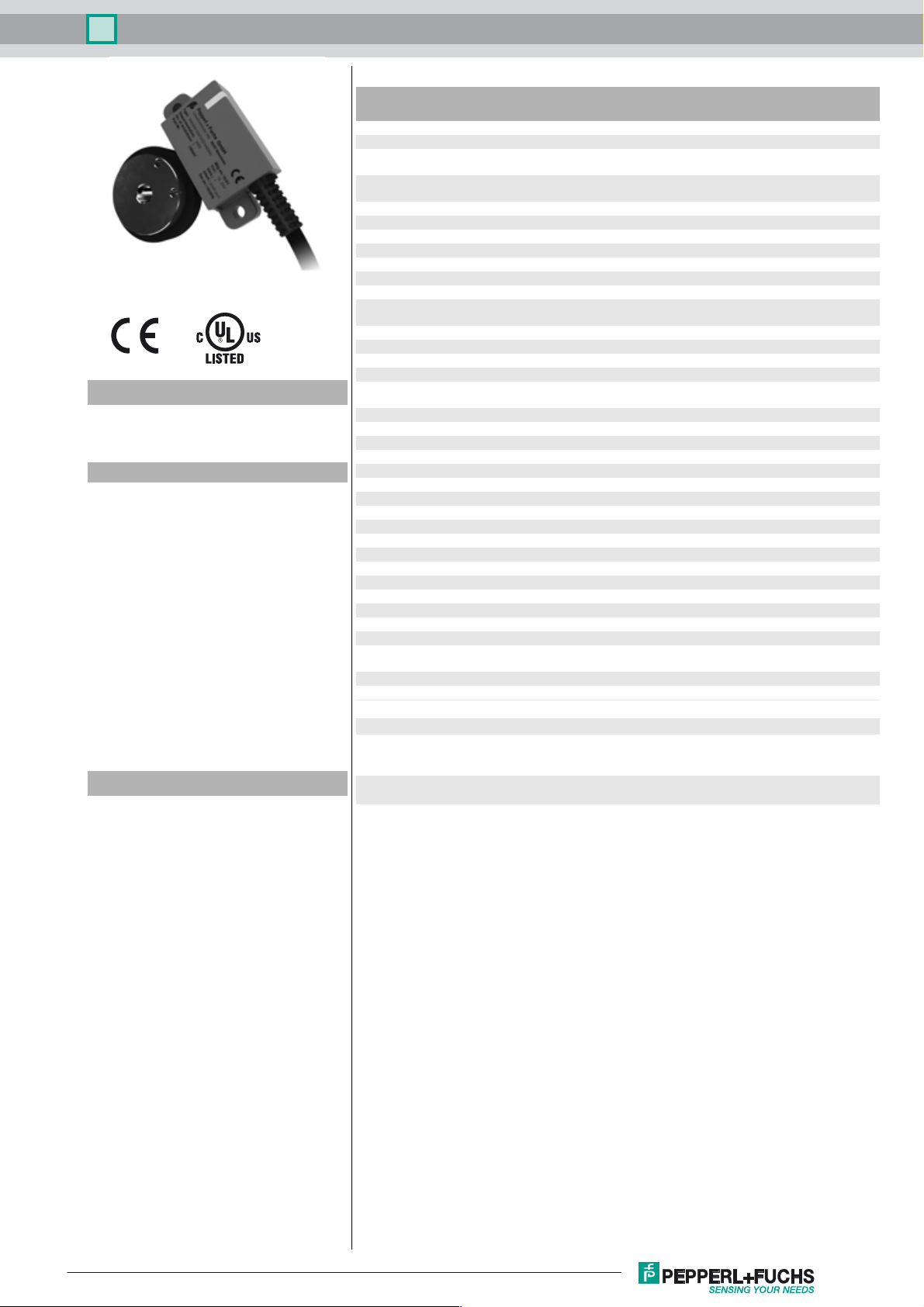
Incremental rotary encoder MNI40N
Technical data
General specifications
Detection type magnetic sampling
Pulse count max. 7200
Model Number
MNI40N
Magnetic, Non Contact
Features
•Clear function verification via twocolor LEDs (red/green)
• Simple installation and adjustment
using assistance functions reduce
costs
• Self-diagnostics including the
magnetic wheel provide quality
assurance
• Internal intelligence provides easy
setup and reliable operation
• The elastomer coating of the
magnetic wheel provides
resistance to dirt as well as
thermal and mechanical shock
• Long service life at high speeds
and temperatures
Description
The magnetic incremental encoder MNI40
combines an exceptionally robust measurement
system with intelligent diagnosis and alignment
functions in the smallest space. Its highly compact
encapsulated housing gives the sensor its high
resistance to harsh environmental conditions. The
installation-friendly design and simple guided
adjustment of the sensor using two-color status
LED reduces the installation time considerably.
UL File Number E223176 "For use in NFPA 79 Applications only" , if UL
Functional safety related parameters
MTTFd 942 a
Mission Time (T
Diagnostic Coverage (DC) 0 %
Indicators/operating means
LED red/green Operating display / Alignment aid
Electrical specifications
Operating voltage U
No-load supply current I
Output
Output type push-pull, incremental or RS-422, incremental
Voltage drop U
Load current max. per channel 30 mA , short-circuit protected (max. per
Output frequency max. 1 MHz
Connection
Cable Ø4.7 mm, 8 x 0.128 mm2, 2 m
Standard conformity
Degree of protection DIN EN 60529, IP67 , IP68 , IP69K
Climatic testing DIN EN 60068-2-30
Emitted interference EN 61000-6-4:2007/A1:2011
Noise immunity EN 61000-6-2:2005
Shock resistance DIN EN 60068-2-27, 200 g, 6 ms
Vibration resistance DIN EN 60068-2-6, 40 g, 10 ... 2000 Hz
Ambient conditions
Operating temperature -40 ... 100 °C (-40 ... 212 °F)
Storage temperature -40 ... 100 °C (-40 ... 212 °F)
Mechanical specifications
Material
Housing PA
Cable PUR
Magnetic wheel steel 1.4021 (AISI 420)
Mass approx. 190 g
Rotational speed max. 30000 min
Approvals and certificates
UL approval cULus Listed, General Purpose, Class 2 Power Source,
Maximum permissible ambient
temperature
) 20 a
M
B
0
d
marking is marked on the product.
10 ... 30 V DC
5 V DC for RS-422
max. 55 mA
< 2.5 V
channel 20 mA, conditionally short-circuit proof)
ferrite filled cured rubber
-1
Type 1 enclosure , if UL marking is marked on the product.
adapters providing field wiring on request
≤ 75 °C (≤ 167 °F)
Release date: 2018-04-20 14:46 Date of issue: 2018-04-20 t42651_eng.xml
Refer to “General Notes Relating to Pepperl+Fuchs Product Information”.
1

Incremental rotary encoder MNI40N
Dimensions
48
22.4
LED
11.2
5.7
ø 6H7
40
32
ø 5
0.2 ... 0.5
ø 3.8
2 x screw M3
for attaching the
magnetic wheel
12
5
10
Electrical connection
Signal Cable, 8-core
GND White
+U
Screen -
Poles
50 31.7 21.96
64 40.6 26.356
72 45.7 28.96
b
10
12
15
10
12
15
10
12
15
Ø d
[mm]
19.05
20
Ø D
[mm]
20
24
25
30
X
[mm]
H7
d
D ± 0.05
X ± 0.15
Brown
A Green
BGrey
Yellow
A
Pink
B
0Blue
Red
0
Release date: 2018-04-20 14:46 Date of issue: 2018-04-20 t42651_eng.xml
Refer to “General Notes Relating to Pepperl+Fuchs Product Information”.
2

Incremental rotary encoder MNI40N
Signal outputs
90˚ ± 45˚ 50 % ± 25 %
! ccw - with top-view
A
A
B
B
0
25 % ± 10 %
0
LED-Indicators
LED status Description
Green On Sensor self test and magnetic wheel verification successfully completed.
Green Flashing Sensor waiting to complete single magnetic revolution for code wheel verification process.
Warning
Red Flashing
Red On
Alignment or wheel velocity detected as out of specified limits.
Possible cause: improper alignment (large sensor-wheel gap, magnetic wheel misalignment, … )
Error
Possible reason:
• Supply voltage drop
• Magnetic wheel not detectable (e. g. too large gap)
• Broken magnetic wheel
Mounting information
Installation Shaft displacement Angular displacement
max. ±1 mm±1 mm
orient magnetic
wheel flush
to the sensor
housing
2x M3 screw
for attaching
the magnetic
wheel
max. ±3°
max. ±3°
Release date: 2018-04-20 14:46 Date of issue: 2018-04-20 t42651_eng.xml
Refer to “General Notes Relating to Pepperl+Fuchs Product Information”.
3

Incremental rotary encoder MNI40N
Order code
MN I 4 0 N – K 2 6 N –
Pulse count see below
Te m p er a t u re
N normal
Output type
1 10 V ... 30 V, push-pull
6 5 V, RS 422
Signal output
+ B + 0
Magnetic wheel specifications
01
A1 64 Poles, Ø40.6 mm
E1 72 Poles, Ø46 mm
Bore hole of magnetic wheel
0S Ø6 mm
0A Ø10 mm
0B Ø12 mm
0T Ø15 mm
2B Ø19.05 mm (only with A1)
0F Ø20 mm (only with A1 and E1)
0G Ø24 mm (only with E1)
0H Ø25 mm (only with E1)
0I Ø30 mm (only with E1)
Housing material
N Plastic
Ver si on
MNI Magnetic principle, Non-contact, Incremental
6 A + B + 0 and A
Connection type
K2 Cable, 2m
50 Poles, Ø31.7 mm (1.25’’)
Pulse counts: 50, 100, 200, 500, 800, 1000, 1250, 1600, 2400, 2500, 5000
Pulse counts: 64, 128, 512, 1024, 1600, 2048, 3072, 3200
Pulse counts: 360, 1800, 3600, 7200
Release date: 2018-04-20 14:46 Date of issue: 2018-04-20 t42651_eng.xml
Refer to “General Notes Relating to Pepperl+Fuchs Product Information”.
4
 Loading...