


PG2000®
Installation Manual
Model No.s 840240 840241 840242
U.S. Patent Numbers 5,802,227; 5,825,954; 5,680,496; 6,002,216
Pentair Water Pool and Spa, Inc.
1620 Hawkins Ave., Sanford, NC 27330 • (919) 566-8000
10951 West Los Angeles Ave., Moorpark, CA 93021 • (805) 523-2400
Visit us on the Internet at: www.pentairpool.com or www.staritepool.com
Rev. C 7-29-05 |
1 |
P/N 840259 |

IMPORTANT SAFETY INSTRUCTIONS
When installing and using this electrical equipment, basic safety precautions should be followed, including the following:
READ AND FOLLOW ALL INSTRUCTIONS
1.WARNING: To reduce the risk of injury, do not permit children to use this product unless they are closely supervisedatalltimes.
2.Check your local building codes before installation to ensure the PG2000 is located at least 5 feet from the pool,ortheminimumdistancefromthepoolthatlocalcodesrequire.
3.Theelectricalsupplyforthisproductmustincludeasuitableratedswitchorcircuitbreakertoopenall ungroundedsupplyconductorstocomplywithSection422-20oftheNationalElectricalCode,ANSI/ NFPA 70-2002. The disconnection means must be readily accessible to pool and spa users, but installed at least 5 feet (1.5m) from the pool or spa water.
 WARNING
RISK OF ELECTRICAL SHOCK OR ELECTROCUTION
This PG2000 must be installed by a licensed or certified electrician in accordance with the National Electrical Code and all applicable local codes and ordinances. Improper installation will create an electrical hazard which could result in death or serious injury to pool users, installers, or others, due to electrical shock, and may also cause property damage.
Disconnect all power before starting the installation process to all associated pool equipment. Failure to do so may lead to severe electrical shock, which can result in death or severe personal injury.
 WARNING
Before installing this FIBERworks® product, read and follow all warning notices and instructions accompanying this light product. Failure to follow safety warnings and instructions can result in severe injury, death, or property damage. You are going to be using a sophisticated device which requires knowledgeable handling in order to insure its optimum performance. Please do not touch anything until you have read and understood these instructions. If you have any questions, please call our service hotline, Monday through Friday, 7:30 a.m. to 4:30 p.m.: (800) 831-7133.
 WARNING
It is recommended that FIBERworks® be installed by trained and certified FIBERworks® dealers only. This installation manual assumes that your PG2000 will be properly installed in full accordance with the instructions provided, the National Electrical Code, and any local codes applicable for an electrical installation of this type.
SAVE THESE INSTRUCTIONS.
P/N 840259 |
2 |
Rev. C 7-29-05 |

|
Table of Contents |
|
SECTION I. |
Before You Begin Installation. . . . . . . . . . . . . . . . . . . . . . . . . . . . . . . . . . . . . . . . . . . . . . . |
4 |
The Installer’s Ten Laws of FIBERworks® . . . . . . . . . . . . . . . . . . . . . . . . . . . . . . . . . . . . . . . . . . . . . . . . . . . . . . . . . . . . . . . . . . . . . . . . . . . . . . . . . . |
4 |
|
The Pool Designer/Salesperson’s Ten Laws of FIBERworks® . . . . . . . . . . . . . . . . . . . . . . . . . . . . . . . . . . . . . . . . . . . . . . . . . . . . . . . . |
5 |
|
A. FIBERCAD Design Assistance . . . . . . . . . . . . . . . . . . . . . . . . . . . . . . . . . . . . . . . . . . . . . . . . . . |
6 |
|
B. Wide Angle Lens positioning with the PG2000 centered at end of the pool . . . . . . . . . . . . . . . . . |
6 |
|
C.Wide Angle OptiFusion Lens positioning on the side of the pool with the PG2000
centered on side of pool . . |
. . . . . . . . . . . . . . . . . . . . . . . . . . . . . . . . . . . . . . . . . . . . . . . . . . . . . . |
6 |
|
SECTION II. |
Running Conduit . . |
. . . . . . . . . . . . . . . . . . . . . . . . . . . . . . . . . . . . . . . . . . . . . . . . . . . . . . |
8 |
SECTION III. |
Installing Lens Housings. . . . . . . . . . . . . . . . . . . . . . . . . . . . . . . . . . . . . . . . . . . . . . . . . . |
9 |
|
SECTION IV. |
Preparing to Mount the PG2000 . . . . . . . . . . . . . . . . . . . . . . . . . . . . . . . . . . . . . . . . . . . . |
9 |
|
SECTION V. |
Feeding or Pulling the AmerGlow Cable . . . . . . . . . . . . . . . . . . . . . . . . . . . . . . . . . . . . . . |
11 |
|
SECTION VI. |
AmerGlow Lens Assembly . . . . . . . . . . . . . . . . . . . . . . . . . . . . . . . . . . . . . . . . . . . . . . . . |
12 |
|
SECTION VII. |
Installing the Ferrule Assembly . . . . . . . . . . . . . . . . . . . . . . . . . . . . . . . . . . . . . . . . . . . . . |
17 |
|
SECTION VIII. |
Installing the PG2000 . . . . . . . . . . . . . . . . . . . . . . . . . . . . . . . . . . . . . . . . . . . . . . . . . . . . |
22 |
|
SECTION IX. |
Synchronization of SAm®/SAL® and Fiberworks® (Wiring Diagrams) . . . . . . . . . . . . . . . . . |
25 |
|
SECTION X. |
Technical Data . . . . |
. . . . . . . . . . . . . . . . . . . . . . . . . . . . . . . . . . . . . . . . . . . . . . . . . . . . . . |
27 |
PG2000 Specifications |
|
|
|
Electrical |
|
|
|
InputVoltage |
.............................. |
120 V @ 2 A |
|
PowerConsumption ................... |
Approximately200Watts |
|
|
Mechanical |
|
|
|
Dimensions ................................. |
|
15 in. x 10½ in. x 12 in. |
|
Weight ....................................... |
|
20 lbs. |
|
Materials .................................... |
|
Highstrengthplastic |
|
This unit will accommodate up to 600 FIBERworks® fibers.
Contents of the Shipping Carton
This package should contain all of the following items:
√PG2000®
√Sub-terrainMountingBase
√FerruleKit
√PG2000InstallationManual-(thismanual)
√Owner'sManual
√WarrantyRegistrationCard
To perform this installation, you will need the following items:
Electricalwireandconduittoconnectmainpower,FIBERworks® cableandfittingsasrequired, ProfessionalTerminationKit,(p/n21005500),andthetools/equipmentlistedinrelevantsectionsofthis manual.
Rev. C 7-29-05 |
3 |
P/N 840259 |
SECTION I. Before You Begin Installation
The Installer’s Ten Laws of FIBERworks®
1.DO NOT ATTEMPT INSTALLATION WITHOUT RECEIVING CERTIFIED TRAINING OR WATCHING INSTALLATION VIDEO.
2.Takeyourtimeandbepatientwhenterminating-Rushinga90secondFiberKnife400fiberterminationcan cause30%lossoflight.
3.UseonlyprescribedTerminationtools-FIBERworks® FiberKnifeandshield.
(DO NOT USE MECHANICAL CUTTERS OR KNIFE BLADE HEATED WITH TORCH.)
4.Make conduit runs as direct as possible - plastic fiber loses 2% of light per foot; see Table 1, Light TransmissionVersusDistance.
5.When handling the cable do not bend final 12 in. of cable before lens.
6.Push lens and final 1 in. of cable into lens body - DO NOT PULL IN!
7.Sub-terrain Mounting Baseshouldbeinstalled below grade so that bottom of PG2000 isator slightly above finishedlandscapeorconcretegradeandprotectedfromgrass.
Locate the PG2000 above water level whenever possible. If raised water features are being lit, be sure theendoftheconduitinsidetheGeneratorisfilledwithRTV,othersuitablesealantorconduitsealkit #22002000 and locate the Generator so water will drain away from it and not accumulate inside of or aroundthePG2000.Thiswillpreventwaterfromfloodingtheelectricalportionoftheunit.
8.Be sure conduits are located by cable size as in the template in the back cover of this manual and cut off level withtopofSub-terrainBase(finishedgrade).
9.PROPER TERMINATION AT PG2000; see PG2000 Installation Steps.
a.First, mechanically cut all cables to equal length about 14 in. above the top of the Sub-terrain Base.
b.Strip all cable jackets 0-2 in. above Sub-terrain Base.
c.SANITY SAVERone wrap of electrical tape over fiber bundle end.
d.Install ferrule and tighten with 3-4 in. of fiber extending out of fiber disk; see Picture 9, pg. 20.
e.Hot knife cut. Hold blade angled at 15 degrees, as if you were cutting cream cheese. Don’t stop and restart, but rather keep continuous light pressure. Don’t saw or wiggle knife. Ease up pressure as you come to end of cut.
f.Besureferruleisfullyrotatedandsecuredbyferrulethumbscrews.
g.Wrap electrical tape or tie wrap around bundle at 2-3 in. above conduit.
10. WHEN IN DOUBT CALL your FIBERworks® Specialist or Technical Service at 800-831-7133.
P/N 840259 |
4 |
Rev. C 7-29-05 |

The Pool Designer/Salesperson’s Ten Laws of FIBERworks®
1.The color of fiber optics is fantastic... but don’t just sell fiber optics, sell FIBERworks®! More Light... More Color...MoreFriendlythanothersimilarfiberopticsystems...fromtheWorld’sLeadingManufacturerof UnderwaterLights!
2.Delightyourcustomersandgetreferrals. Don’tundersize-neverusefewerfibersorfewerlightsthan recommended.
3.The Longer the fiber optic cable, the more it will cost and the less light it will transmit to the pool, spa, water featureorlandscapelight. Distancecosts2%oflightperfoot;seeTable1,LightTransmissionVersus Distance.
4.ChooseyourPG2000location(s)wisely. Giveyourbiggestcablestheshortestruns. Ifyoudesign“never ending” decks, design a planter between 5 and 10 feet (depending on code) from the primary lens location.
5.Colored surfaces absorb light. The darker the surface, the more light it will absorb. Do not waste your customer’smoneyonunderwaterfiberopticsfordarksurfaces.Theywillnotfullyappreciatethedramaticsof fiberopticcolors. UseAmerlites®,AquaLights® orHiLites®.
6.The darker your pool surface, the more dramatic will be perimeter FIBERworks®. Dark pools make great reflectingpoolsandfantasticperimeterFIBERworkspools.Forperimeterinstallationsover200'consultyour FIBERworks® Specialist.
7.FIBERworks® powerfullyilluminatesthewallandfloorsurfacetowardwhichthelensispointed...modest illumination is on the wall which holds the lens. AmerGlow 12, 30, 50, 70 or 100 cables make great step lights and shadow fillers when directed toward or across the wall holding the AmerGlow 325, 225 or 170 cables.
8.There aretwounderwaterlensesavailable.TheWideAngleLensspreads lightabout180degreesandshould be used for most underwater applications. The Standard Lens spreads light about 70 degrees and should be usedforoppositewallshadowfilling,uplightingintoafountainhead,anduplightingintoawaterfallorcascade.
9.AlwaysuseCertifiedFIBERworks®Installers.Arushedorpoorinstallationcankillperformanceby30%. Schedule training as soon as possible or order FIBERworks® Installation Video [P/N P3-202].
10.WHEN IN DOUBT CALL Technical Service at 800-831-7133 ORcomplete a FIBERCAD FORM (located in the Pentair Water Pool and Spa, Inc. Catalog), AND fax a scale drawing to 727-461-5080.
NOTE
FIBERworks Application Manual is available on-line @ www.pentairtraining.com and www.pentairpool.com.
Rev. C 7-29-05 |
5 |
P/N 840259 |

A. FIBERCAD Design Assistance.
NOTE
FIBERworks Application Manual is available on-line @ www.pentairtraining.com and www.pentairpool.com.
Forassistanceindesigningyourfiberopticlighting,faxaFIBERCADform(locatedinthePentairWater Pool and Spa, Inc. Catalog) and scale drawing to 727-461-5080.
If designing your own lighting layout, it is critical to keep the PG2000 as close to the pool as possible (less than15’isdesirable)andcablerunsasshortaspossibletomaximizelightoutput;seeTable 1,Light TransmissionvsDistance.
B.Wide Angle Lens positioning with the PG2000 centered at end of the pool.
1.AmerGlow 170, 225 and 325 only, with the lens(es) positioned at the end of the pool. Whenever possible, the lens(es)shouldnotfacedirectlytowardthehomeorentertainmentarea.
a.Forwhiteornearlywhiteconcrete,fiberglassorvinylpools,WideAngleLensesintendedtoilluminatethe entire length of the pool can be placed in either the shallow end or deep end 6 to 8 inches below water level.
b.For light or medium colored pools, place the Wide Angle lens(es) in the deep end 6 to 8 inches below waterlevel.
c.Use single AmerGlow 170, 225, 325 in center of end wall or Dual AmerGlow 170’s or 225’s each 2 to
3.5feet from center line (4 to 7 feet apart). Pools over 18 feet wide should have dual lenses in the end wall.
C.Wide Angle OptiFusion Lens positioning on the side of the pool with the PG2000 centered on side of pool.
1.AmerGlow 100, 70, 50 and 30 only, unless pool is over 20 ft. wide, with the lens(es) positioned at the side of thepool.Wheneverpossible,thelens(es)shouldnotfacedirectlytowardthehomeorentertainmentarea.
a.Lensesshouldbelocatedanddirectedtoofferuniformilluminationoftheentirepoolallocatingmorelight for areas with greater floor and wall surface area such as the deep end. Also see Light Transmission vs Distancetableformorehelp.
b.Thebestlightingisachievedonthesurfacesthelensisfacing.
c.Lens(es)inconcreteorfiberglasspoolsshouldbelocatedapproximately1/3ofthedistancebetweenthe watersurfaceandthebeginningofthetransitionfromwalltofloor.
• Place 9 in. below water level in 3 foot shallow ends to reduce the intensity of hot spots on the floor.
d.Invinylpools,locatelens(es)asfollows:
DEPTH |
INCHES BELOW |
|||
TOP OF PANEL |
||||
|
|
|||
|
|
|
|
|
3 |
ft. |
12 |
in. |
|
|
|
|
|
|
4 |
ft. |
12 |
in. |
|
|
|
|
|
|
5 |
ft. |
15 |
in. |
|
|
|
|
|
|
6 |
ft. |
15 |
in. |
|
|
|
|
|
|
7 |
ft. |
18 |
in. |
|
|
|
|
|
|
8 |
ft. |
18 |
in. |
|
|
|
|
|
|
9 |
ft. |
21 |
in. |
|
|
|
|
||
10 ft. |
21 |
in. |
||
|
|
|
|
|
P/N 840259 |
6 |
Rev. C 7-29-05 |

|
|
|
|
TABLE 1. |
|
|
|
|
||
|
|
|
|
|
|
|
|
|
|
|
|
|
|
FIBER EQUIVALENT LIGHT TRANSMISSION at 10 ft. |
|
|
|||||
|
|
|
|
|
|
|
|
|
|
|
|
|
|
|
AMERGLOW CABLE SIZES |
|
|
|
|||
|
|
|
|
|
|
|
|
|
|
|
Cable |
325 |
225 |
170 |
100 |
70 |
|
50 |
30 |
12 |
% of Light |
Length |
fiber equiv. |
fiber equiv. |
fiber equiv. |
fiber equiv. |
fiber equiv. |
|
fiber equiv. |
fiber equiv. |
fiber equiv. |
Lost |
10 |
325 |
225 |
170 |
100 |
70 |
|
50 |
30 |
12 |
|
12 |
312 |
216 |
163 |
96 |
67 |
|
48 |
29 |
12 |
4.0% |
14 |
300 |
208 |
157 |
92 |
65 |
|
46 |
28 |
11 |
7.8% |
16 |
288 |
199 |
151 |
89 |
62 |
|
44 |
27 |
11 |
11.4% |
18 |
276 |
191 |
145 |
85 |
60 |
|
43 |
26 |
10 |
14.9% |
20 |
266 |
184 |
139 |
82 |
57 |
|
41 |
25 |
10 |
18.3% |
25 |
240 |
166 |
126 |
74 |
52 |
|
37 |
22 |
9 |
26.1% |
30 |
217 |
150 |
113 |
67 |
47 |
|
33 |
20 |
8 |
33.2% |
35 |
196 |
136 |
103 |
60 |
42 |
|
30 |
18 |
7 |
39.6% |
40 |
177 |
123 |
93 |
55 |
38 |
|
27 |
16 |
7 |
45.4% |
45 |
160 |
111 |
84 |
49 |
35 |
|
25 |
15 |
6 |
50.7% |
50 |
145 |
100 |
76 |
45 |
31 |
|
22 |
13 |
5 |
55.4% |
55 |
131 |
91 |
68 |
40 |
28 |
|
20 |
12 |
5 |
59.7% |
60 |
118 |
82 |
62 |
36 |
25 |
|
18 |
11 |
4 |
63.6% |
70 |
97 |
67 |
51 |
30 |
21 |
|
15 |
9 |
4 |
70.2% |
80 |
79 |
55 |
41 |
24 |
17 |
|
12 |
7 |
3 |
75.7% |
90 |
65 |
45 |
34 |
20 |
14 |
|
10 |
6 |
2 |
80.1% |
100 |
53 |
37 |
28 |
16 |
11 |
|
8 |
5 |
2 |
83.8% |
|
|
|
|
|
|
|
|
|
|
|
Thistableshowstheeffectoflongercablerunsonlighttransmission. Longercablerunshavethesameeffectascutting downonthenumberoffibers.
** The first 10’ is considered unavoidable and is used here as a standard for comparison.
(For example: 69' of 325, 50' of 225 and 37' of 170 all have the same output as 10' of 100.)
 WARNING
Provide adequate lighting to your pool for nighttime use. The amount of light needed will vary with the size and shape of the pool. This may require additional lighting sources. Failure to provide adequate lighting can result in swimming and diving hazards that can cause severe injury or death. Consult your local building department or a lighting professional to determine lighting requirements.
Rev. C 7-29-05 |
7 |
P/N 840259 |
SECTIONII. RunningConduit
A.General conduit tips.
•Use electrical sweep elbows and 45’s or heat bend PVC pipe. DO NOT use plumbing 90° or 45° elbows. Using therightconduitandfittingswillallowthecabletobefedmucheasier,andwillpreventdamagetothefiberoptics.
•Use rigid PVC pipe or SMOOTH ID flexible electrical PVC for all cable runs. Flexible water PVC pipe is not recommended for this type of installation because of its high friction walls.
•Make your job easier - use electrician’s lube when feeding cable.
B.Choosing the best size conduit for the job.
a.For AmerGlow 325, 225 or 170 use 1 in. or larger rigid PVC conduit; use 1½ in. for AmerGlow 325 over 20 ft.
b.Use ¾ in. or larger conduit for AmerGlow 100 or 70.
c.Use ½ in. or larger conduit for AmerGlow 50, 30 or 12.
NOTE
Do not reduce fiberglass lens housing or standard gunite lens housing to less than 1 in. in rear socket or lens assembly will not seat properly.
C.Electrical conduit requirements, see Wiring the PG2000 for Wiring Diagram.
a.For manual operation at PG2000, RF2000 Wireless Control or single remote toggle switch operation, use
½ in. electrical conduit to run 3 - 18 AWG (black, white and green) or larger wires to each PG2000 location.
b.For dual remote toggle switch or automated remote control operation (Compool, etc.), use ½ in. electrical conduittorun4 - 18AWG(red,black,whiteandgreen)orlargerwirestoeachPG2000location.
c.It is very important that the unit be properly grounded - there is serious risk of electrical shock or electrocutionotherwise.
 WARNING
The PG2000 must be properly grounded. Consult the National Electrical Code and all other applicable local codes and ordinances for proper grounding techniques. Improper installation will create an electrical hazard which could result in death or serious injury to pool users, installers, or others, due to electrical shock, and may also cause property damage.
d.MakesuretheconduitcomesupinthecorrectareainthefrontofthePG2000;seeSectionIVforthisinformation.
e.Extend conduit up above the bottom of the PG2000 at least six inches.
D.Running the conduit for AmerGlow fiber optic cable.
a.Using the sizes determined above, run the conduit from the pool wall to the PG2000 location.
b.ConduitnearthePG2000shouldbeatleast4in.deepifusingthesub-terrainmountingbasetomountthePG2000.
c.Use only electrical sweep elbows and 45’s - DO NOT use plumbing 90’s or 45’s, as they can damage the fiber optics or prevent pulling the cable.
d.The lens body should be located according to recommendations in the“Before You Begin Installation...” Section. Conduit should slope to that depth.
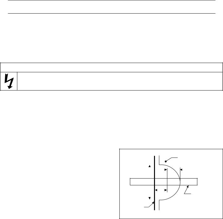
e. |
If using smaller than 1 in. conduit, do not bush down |
|
|
|
|
|
|
Gunite |
||
|
within 2 in. from rear of lens body. |
|
|
|
|
|
|
|
|
|
f. |
Usea12in.minimumstraightsectionofconduit |
|
|
|
|
|
|
|
|
1¼ in. min. |
|
4 in. |
|
|
|||||||
|
behindthelenshousing. |
|
|
|
|
|||||
|
|
|
|
|
|
|
|
|
|
|
|
|
|
|
|
|
|
|
|
|
|
g. |
For gunite pools, the recessed cut back for lens |
|
|
|
|
|
|
|
|
|
|
housingshouldbeasshown in Figure1. Dimension |
|
|
|
|
|
|
|
|
|
|
|
|
|
|
|
A |
|
|
Conduit |
|
|
“A” should be 1 in. for a FIBERworks Standard |
|
|
|
|
|
|
|
||
|
Gunitefitting,and1½in.foraFIBERworksInvisible |
|
|
|
|
|
|
|
|
|
|
Plaster |
|
|
|
||||||
|
Gunitefitting. |
|
|
|
||||||
|
|
Surface |
|
|
Figure 1. |
|||||
|
|
|
|
|
|
|
|
|
|
|
P/N 840259 |
8 |
Rev. C 7-29-05 |

h.At the PG2000 location, leave at least 6 in. of conduit above the anticipated sub-terrain mounting base or deck surface and place tape over both ends of conduit. The tape and extralength will help prevent debris fromgetting into the conduit until the cable is run. The conduit should be cut off level with top of Sub-terrain Base (finished grade) location just before the fiber optic cable is run (does not apply to electrical conduit).
i.Use the template on the back page of this manual to determine conduit location inside the PG2000 if you are installing on a poured concrete deck, on a wood deck or intheground.
(FINISHED LANDSCAPE OR DECK LEVEL)
Figure 2.
j.For either type of installation, use duct tape or tie wrap to bundle the conduit together in the PG2000 area. Keeping the conduit together will help when preparing the cable later.
SECTIONIII. Installing Lens Housings
•FIBERworks® lenshousingsareinstalledthesamewayregularwaterreturnfittingsareinstalled.
 CAUTION
Use only FIBERworks lens housings. Other fittings will not seal conduit. Each FIBERworks lens housing has a label identifying it as such. Do not use excessive glue, as the overflow may run onto the O-ring sealing surface.
SECTIONIV. Preparing to Mount the PG2000
A.Choose one of the following two methods for installation of the PG2000.
1.MountthePG2000on BURIEDSub-terrain Mounting Base(included). This allowsthe unit to belocated away from the deck, for example, in a garden near the pool, among some shrubbery, etc. Be sure the unit is situated such that the air vents are not going to be blocked by overgrowth. The sub-terrain mounting base can also be poured into the concrete deck or pad.
2.Mount the PG2000 directly onto a flat concrete surface or a wood deck without the Sub-terrain Base using the lagscrews,washersandanchors(included).
B.Installing the Sub-Terrain mounting base; see Figure 2 and Pictures on pg. 10.
1.If conduit has already been run, set mounting base over top of conduit to determine if the bottom flange or side arches need to be cut. The top shoulder of the base should be at or slightly above finished landscape or deck level.
2.Leveled base can be secured in place with 3/8 in. rebar angled through holes provided in corners of bottom flange, see Picture 3 on pg. 10
3.Cut fiber conduit below or at top of base and cut electrical conduit 6 in. above finished landscape or deck level, see Figure 2.See PG2000 Conduit Template on pg. 28 of these instructions.
Note
Flat side of base is back of the PG2000. Locate this side away from line of site to the PG2000.
C.Mounting to a wood deck or a poured concrete surface.
1.Whatyou’llneed:
√Drillwith½in.MasonryBit
√Hammer
√½ in. Nut Driver
(continuedonpage11)
Rev. C 7-29-05 |
9 |
P/N 840259 |
 Loading...