


|
|
Installation and |
|
|
|
® |
User’s Guide |
|
|
||
IntelliFlo® VS-3050
Variable Speed Programmable Pump
IMPORTANT SAFETY INSTRUCTIONS READ AND FOLLOW ALL INSTRUCTIONS SAVE THESE INSTRUCTIONS
P/N 357219 - REV. A - MARCH 10, 2008
Pentair Water Belgium bvba Industriepark Wolfstee Toekomstlaan 30 B-2200 Herentals - Belgium +32 (0) 14.25.99.11
www.pentairpooleurope.com
English
Français Nederlands Deutsch
Español
Italiano

English
Customer Support
HERENTALS, BELGIUM (8:30 A.M. to 4:30 P.M.) CET
Phone: + 32 (0) 14 25 99 11
Website: www.pentairpooleurope.com
Declaration of Conformity
We declare, under our sole responsibility, that the product identified in this declaration, and to which this declaration relates, are in conformity with the protection requirements of Council Directive 98/
37/EEG
•Standard EN60335-1, EN50178, EN61800-5-1
•Standard EN61800-3, EN61000-6-2, EN61000-6-4
Manufacturer: Pentair Water Pool and Spa, Inc.
© 2007 Pentair Water Pool and Spa, Inc. All rights reserved This document is subject to change without notice
Trademarks and disclaimers: IntelliFlo® and Pentair Pool Products® are trademarks and/or registered trademarks of Pentair Water Pool and Spa, Inc. and/or its affiliated companies in the United States and/or other countries.Unless noted, names and brands of others that may be used in this document are not used to indicate an affiliation or endorsement between the proprietors of these names and brands and Pentair Water Pool and Spa, Inc. Those names and brands may be the trademaks or registered trademarks of those parties or others.
P/N 357219 - REV. A - MARCH 10, 2008

Contents |
|
Important Safety Precautions |
4 |
Section 1: IntelliFlo® Overview |
7 |
IntelliFlo® VS Variable Speed Pump |
7 |
Features |
8 |
IntelliFlo® VS Motor Assembly |
8 |
IntelliFlo® VS Drive Assembly and Control Panel |
8 |
IntelliFlo® VS Operator Control Panel |
9 |
Controls and LEDs |
9 |
Section 2: Operating IntelliFlo® VS |
10 |
Setting the pump preset speed |
10 |
Adjusting the pump speed |
10 |
Starting the pump |
11 |
Stopping the pump |
11 |
Resetting the pump to factory defaults |
11 |
Priming the pump for the first time or after service |
12 |
Priming the Pump |
13 |
Section 3: User Maintenance |
14 |
Pump Strainer Basket |
14 |
Pump Strainer Basket Service |
14 |
Motor Service |
15 |
Winterizing |
16 |
Priming the pump after service |
16 |
Section 4: Installation and Removal |
17 |
IntelliFlo® VS Kit Contents |
17 |
Installing IntelliFlo® VS |
17 |
Location |
17 |
Piping |
17 |
Check Valve |
17 |
Wiring the IntelliFlo® VS |
18 |
Pump Disassembly |
19 |
Pump Reassembly/Seal Replacement |
20 |
Shaft Seal Replacement |
20 |
Drive Assembly Removal and Installation |
21 |
Illustrated Parts List |
22 |
IntelliFlo® Pump Dimensions |
23 |
IntelliFlo® Flow and Power vs Flow Pump Curve |
23 |
IntelliFlo® VS Electrical Specifications |
23 |
Section 5: Troubleshooting |
24 |
Warning and Alarm conditions |
24 |
Alarm and warning LED sequence |
24 |
General IntelliFlo® VS Troubleshooting Problems |
25 |
3
English

4
English
IMPORTANT SAFETY PRECAUTIONS


 Important Notice:
Attention Installer: This manual contains important information about the installation, operation and safe use of this product. This information should be given to the owner and/or operator of this equipment.
 WARNING — Before installing this product, read and follow all warning notices and instructions which are included. Failure to follow safety warnings and instructions can result in severe injury, death, or property damage.
 WARNING — Entrapment Avoidance Notice:
The suction outlet connected to a swimming pool or spa pump can pull a high vacuum if it is blocked. Therefore, if only one suction outlet smaller than 46 cm x 58 cm is used, anyone blocking the suction outlet with their body can be trapped and held against the suction outlet. Disembowelment or drowning can result. Therefore, if small suction outlets are used with this pump, to prevent this entrapment and possible death, install at least two suction outlets in the body of water. Separate these suction outlets as described in the International Residential Code (IRC), the International Business Code (IBC), the Consumer Products Safety Council (CPSC) Guidelines for Entrapment Hazards: Making Pools and
Spas Safer or ANSI/IAF-7 Standard for Suction Entrapment Avoidance in Swimming
Pools, Wading Pools, Spas, Hot Tubs and Catch Basins. If suction outlets are not used, additional entrapment avoidance measures as described in the CPSC Guidelines orANSI/ IAF-7 should be employed.
The covers used on suction outlets should be approved and listed as conforming to the currently published edition of ANSI/ASME A112.19.8 Standard covering Suction Fittings for Use in Swimming Pools, Wading Pools, Spas and Hot Tubs. These covers should be inspected regularly and replaced if cracked, broken or older than the design lifetime indicated on them by the manufacturer. The maximum possible flow rate of this pump should be less than or equal to the maximum approved flow rate indicated on the suction outlet cover by the manufacturer. THE USE OF UNAPPROVED COVERS ORALLOWING
USE OF THE POOL OR SPA WHEN COVERS ARE CRACKED OR BROKEN CAN RESULT IN HAIR ENTANGLEMENT WHICH CAN RESULT IN DEATH.
 WARNING — Risk of electrical shock or electrocution.
This pool pump must be installed by a licensed or certified electrician or a qualified pool serviceman in accordance with all applicable local codes and ordinances. Improper installation will create an electrical hazard which could result in death or serious injury to pool users, installers, or others due to electrical shock, and may also cause damage to property.
Always disconnect power to the pool pump at the circuit breaker before servicing the pump. Failure to do so could result in death or serious injury to serviceman, pool users or others due to electric shock.

5
IMPORTANT SAFETY PRECAUTIONS (continued)
 WARNING — Water temperature in excess of 100° Fahrenheit may be hazardous to your health. Prolonged immersion in hot water may induce hyperthermia. Hyperthermia occurs when the internal temperature of the body reaches a level several degrees above normal body temperature
of 98.6° F. (37° C.). The symptoms of hyperthermia include: drowsiness, lethargy, dizziness, fainting, and an increase in the internal temperature of the body.
The effects of hyperthermia include: 1) Unawareness of impending danger. 2) Failure to perceive heat. 3) Failure to recognize the need to leave the spa. 4) Physical inability to exit the spa. 5) Fetal damage in pregnant women. 6) Unconsciousness resulting in danger of drowning.
 WARNING — The use of alcohol, drugs, or medication can greatly increase the risk of fatal hyperthermia in hot tubs and spas.
 WARNING — To reduce the risk of injury, do not permit children to use this product unless they are closely supervised at all times.
 WARNING — For units intended for use in other than single-family dwellings, a clearly labeled emergency switch shall be provided as part of the installation. The switch shall be readily accessible to the occupants and shall be installed at least 5 feet (1.52 m) away, adjacent to, and within sight of the unit.
 WARNING — When setting up pool water turnovers or flow rates the operator must consider local codes governing turnover as well as disinfectant feed ratios.
 WARNING — Before servicing the system, switch the main power OFF and remove the communication cable from the pump.
 CAUTION — Install the pump a minimum of 5 feet (1.5 m) from the inside wall of the pool and spa.
 CAUTION — A No. 8 AWG or larger conductor must be wired to the motor bonding lug.
 CAUTION — This pump is for use with permanently installed pools and may also be used with hot tubs and spas if so marked. Do not use with storable pools. A permanently installed pool is constructed in or on the ground or in a building such that it cannot be readily disassembled for storage. A storable pool is constructed so that it may be readily disassembled for storage and reassembled to its original integrity and has a maximum dimension of 18 feet (5.49m) and a maximum wall height of 42 inches (1.07m).
 CAUTION — For hot tubs and spa pumps, do not install within an outer enclosure or beneath the skirt of a hot tub or spa unless so marked.
 CAUTION — IntelliFlo® is capable of generating systems pressures up to 30 meters. Installers must ensure that all system components are rated to withstand at least 30 meters. Over pressurizing the system can result in catastrophic component failure or property damage.
General Installation Information
•All work must be performed by a licensed electrician, and must conform to all EU country, and local codes.
•Install to provide drainage of compartment for electrical components.
English

English
6
IMPORTANT SAFETY PRECAUTIONS (continued)
General Installation Information
 WARNING — Pumps improperly sized or installed or used in applications other than for which the pump was intended can result in severe personal injury or death. These risks may include but not be limited to electric shock, fire, flooding, suction entrapment or severeinjury or property damage caused by a structural failure of the pump or other system component
 WARNING — The pump can produce high levels of suction within the suction side of the plumbing system. These high levels of suction can pose a risk if a person
comes within the close proximity of the suction openings. A person can
be seriously injured by this high level of vacuum or may become trapped and drown. It is absolutely critical that the suction plumbing be installed in accordance with the latest national and local codes for swimming pools.
 WARNING — In a domestic environment, this product may cause radio interference in which case supplementary mitigation measures may be required.
 WARNING — Do not install on IT (insulated terra) mains network (marine applications)
NOTE — If required by local building codes, the pump is to be supplied by an isolating transformer or supplied through a residual current device (RCD) having a residual operating current not exceeding 30 mA.
NOTE — Use only RCD/GFCI suitable for protecting equipment with a DC current content in the fault current.
• These instructions contain information for a variety of pump models and therefore some instructions may not apply to a specific model. All models are intended for use in swimming pool applications. The pump will function correctly only if it is properly sized to the specific application and properly installed.
General Warnings
•Never open the inside or the drive motor enclosure. There is a capacitor bank that holds a 230 VAC charge even when there is no power to the unit.
•The IntelliFlo® VS pump is not submersible
•The IntelliFlo® VS pump is capable of 35 m3/hr or 35 meters of head; use caution when installing and programming to limit pumps performance potential with old or questionable equipment
•Code requirements for the electrical connection differ from state to state. Install equipment in accordance with all applicable local codes and ordinances.
•Always Press the Stop button and disconnect the communication cable before performing maintenance

7
Section 1
Overview
IntelliFlo® VS-3050 Variable Speed Pump
The IntelliFlo® VS-3050 variable speed pump is well suited for all of your pool, spa, cleaner, waterfall and other water application. Using the control panel, IntelliFlo® VS can use one of the four selectable preset speeds or the pump speed can be adjusted to run at a specific speed. IntelliFlo® out performs all conventional pumps in its class.Advanced energy conservation features ensure that your filtration system is operating at peak efficiency.
Features
•Adjusts to various pool sizes
•Prevents thermal overload
•Detects and prevents damage from under and over voltage conditions
•Protects against freezing
•Easy to use operator control panel
•Operator control panel buttons for speed control
•Built-in strainer pot and volute
•Ultra energy-efficient TEFC Square Flange Motor
•Compatibility with most cleaning systems, filters, and jet action spas
•Driver assembly features permanent magnet synchronous motor
•Heavy-duty, durable construction designed for long life
English

English
8
IntelliFlo® VS Motor Assembly
The IntelliFlo® three-phase six-pole motor operates at 3400 RPM (at 92% efficiency) and 1000 RPM (at 90%). The motor assembly is continually cooled by an external fan. Dual seals on the motor shaft and at the fan assembly seal the entire motor from any moisture from entering the motor assembly.
For added protection, a slinger located in front of the main shaft seal assists in slinging water away from the shaft opening in the flange.
Operator Control Panel, |
Control panel cover |
buttons and LEDs |
|
Motor fan cover
Drive assembly and electronics enclosure
 Three Wire Harness
Brown (hot),
Blue (neutral),
Green/Yellow (ground)
IntelliFlo® VS Drive Assembly
Motor assembly
IntelliFlo® VS Motor Assembly
IntelliFlo® VS Drive Assembly and Control Panel
The IntelliFlo drive assembly consists of an operator control panel and the system electronics that drive the motor. The drive microprocessor controls the motor by changing the frequency of the current it receives together with changing the voltage to control the rotational speed.
•Permanent Magnet Synchronous Motor (PMSM)
•High efficiency (3400 RPM 92% and 1000 RPM 90%)
•Superior speed control
•Operates at lower temperatures due to high efficiency
•Same technology as deployed in hybrid electric vehicles
•Designed to withstand outdoor environment
•Totally enclosed fan cooled
•Three-phase motor
•56 Square Flange
•Six-Pole
•Low noise

9
IntelliFlo® VS Operator Control Panel
The IntelliFlo® VS operator control panel provides manual speed controls for the pump. There are four preset speed buttons that can be selected. The Up and Down button is used to adjust the pump speed. The selected speed can be saved and assigned to one of the speed buttons.
English
1
2
5
6
3 4
Controls and LEDs
Speed 1, Speed 2, Speed 3, and Speed 4 button/LED: Press one of the speed buttons to select the desired preset pump speed. The pump preset speeds are: Speed 1 (750 RPM), Speed 2 (1500 RPM), Speed 3 (2350 RPM), and Speed 4 (3110 RPM). The speed button LED is on when the selected button is pressed. If the pump is running and the Up/Down button is used to adjust the speed, the selected speed LEDs will go off.
 Up/Down button: While the pump is running, press the Up or Down button to increase or decrease the pump speed. To save the new pump speed, press any one of the four speed buttons for three seconds to assign the speed to the selected button (the LED be on). Four adjusted pump speeds can be assigned to the speed buttons. When the pump is using an adjusted speed and the pump is powered down, the next time the pump is powered up the pump will use the same speed.
 Start button/LED: Starts the pump using a selected or adjusted speed. This LED is on when the pump is running.
 Stop button: Press this button to stop the pump.
 On LED: This green power LED is on when IntelliFlo® VS is powered up.
 Alarm LED: This LED is on when an error condition occurs. This green LED will flash a certain number of times indicating a specific error condition. For the alarm LED flash sequence, refer to “Alarm and Warning LED Sequence,” Section 5.

English
10
Section 2
Operating IntelliFlo® VS
This section describes how to use the IntelliFlo® 4 pump control panel.
Setting the pump preset speed
IntelliFlo® VS operates using one of the preset speeds. Use the speed buttons to select the preset speeds.
To set the pump speed
1.Ensure that the pump is powered on and the green power LED is on.
2.Press the desired speed button (1- 4) for less than three seconds to select the preset pump speed. When the selected speed button is pressed, the LED is on. The pump preset buttons and speeds are:
Speed 1 button - 750 RPM Speed 2 button - 1500 RPM Speed 3 button - 2350 RPM Speed 4 button - 3110 RPM
3. Press the Start button to start the pump using the selected speed if necessary.
Adjusting the pump speed
IntelliFlo® can be adjusted to run at any speed between 400 RPM and 3450 RPM.
To adjust the pump speed
1. |
Ensure that the pump is powered on and the green power LED is on. |
|
2. |
Press the Start button to start the pump if the pump is not running. |
|
3. |
Press the UP/Down button to increase or decrease the pump speed. |
|
|
• 10 RPM increments: Press and quickly release the Up/Down button to |
|
|
increase or decrease the speed in 10 RPM increments. |
|
|
• 20 RPM increments: Press and hold the Up/Down button to |
|
|
continuously increase or decrease the pump speed. |
|
4. |
Saving an adjusted speed: To save the newly adjusted pump speed, press |
Up/Down button |
|
and hold the desired speed buttons to assign the current speed. Four new |
|
|
|
|
|
pump speeds can be assigned to Speed buttons (1-4). |
|
5. |
Press the Speed button that is assigned to the adjusted speed. |
|
11
Starting the pump
To start the pump
1.Ensure that the pump is powered on and the green power LED is on.
2.Press the Start button (LED on) to start the pump.
Note: When the pump is using a modified speed and is powered down, the next time the pump is powered up, the pump will use that same speed.
Stopping the pump
To stop the pump
•Press the Stop button to stop the pump.
Note: The pump can automatically restart if the communication cable is connected.
Resetting the pump to factory defaults
The IntelliFlo® VS pump can be reset to the factory default settings. All previously adjusted pump speeds that were saved will be erased.
To reset the pump to the factory default settings:
1.Ensure that the pump is powered on and the green power LED is on.
2.Press the Stop button to stop the pump.
3.Press and hold all of the four Speed buttons simultaneously for three seconds. Power off the drive and reenergize. The default settings will be in effect.
English
Control Panel Speed Buttons

English
12
Priming the pump for the first time or after service
Before the IntelliFlo® VS pump is started for the first time it must be primed. To prime a pump means filling the pump and suction pipe with water. This process evacuates the air from all the suction lines and the pump. It may take several minutes to prime depending on the depth of water, pipe size and length. It is easier to prime a pump if you allow all the air to escape from the pump and pipes.The water cannot enter unless the air can escape. Pumps do not hold prime, the pool piping system has that task.
 CAUTION - To avoid permanent damage to the IntelliFlo® VS pump, before starting the pump, fill the IntelliFlo® housing strainer with water so that the pump will prime correctly. If there is no water in the stainer the pump will
not prime.
•NEVER run the pump dry! Running the pump dry may damage the seals, causing leakage and flooding!
•Do not add chemicals to the system directly in front of pump suction. Adding undiluted chemicals may damage the pump and will void the warranty.
•Open gate valves before starting system.
•Pump will prime itself when used in flooded suction system.
•Be sure to release all air from filter and piping system.
•The IntelliFlo® VS pump is a variable speed pump. Typically the lower speeds are used for filtration and heating. The higher speeds can be used for spa jets, water features, and priming.

 CAUTION - Before starting this procedure, first read the following
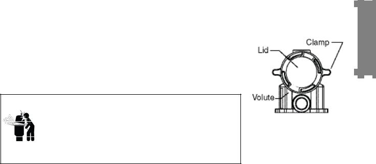
Before removing the pump lid:
1.Press the Stop button if the pump is running before proceeding
1.Disconnect the communication cable from the pump.
2.Close the gate valves in suction and discharge pipes.
3.Release all pressure from pump and piping system.
4.Never tighten or loosen the clamp while the pump is operating.
 WARNING! If the pump is being pressure tested, release all pressure before removing the clamp.
Do not block the pump suction while the pump is running. If a body part blocks the pump suction it may cause severe or fatal injury. Small children using the pool must ALWAYS have close adult supervision.
 WARNING! FIRE and BURN HAZARD - The pump motor may run at a high temperatures. To reduce the risk of fire, do not allow leaves, debris, or foreign matter to collect around the pump motor. To avoid burns when handling the motor, shut off the motor and allow it to cool for 20 minutes before trying to work on it. The IntelliFlo VS provides an automatic internal cutoff switch to protect the motor from heat damage during operation.

13
Priming the pump for the first time or after service (Continued)
Priming the Pump
•Release all pressure from filter, pump, and piping system; see the filter owner’s manual.
•In a flooded suction system (water source higher than pump), the IntelliFlo® VS pump will prime itself when suction and discharge valves are opened.
•If the IntelliFlo® VS pump is not in a flooded suction system, remove clamp and lid ; fill the pump with water.
•Do not lubricate the lid o-ring. The original equipment o-ring contains a permanent internal lubricant.
NOTICE: If you replace the o-ring with a non-internally lubricated o-ring, you may need to apply a silicone based lubricant.
•Clean and inspect o-ring; reinstall on lid.
•Replace clamp on strainer pot; turn clockwise to tighten clamp.
NOTICE: Tighten the pump clamp by hand only (no wrenches)!
Pump should prime now. Priming time will depend on vertical length of suction lift and horizontal length of suction piping. If pump does not prime, make sure that all valves are open, suction pipe end is under water, pump suction is below water level, and that there are no leaks in suction pipe.
To prime the IntelliFlo® VS pump:
1.Turn the pump clamp and lid in a counterclockwise direction until it stops and remove them.
2.Fill the pump strainer pot with water.
3.Reinstall the pump clamp and lid onto the strainer pot. The pump is now ready to prime.
4.Make sure all electrical connections are clean and tight.
5.Open the air release valve on the filter, and stand clear of the filter.
6.Switch the IntelliFlo® pump on at the circuit breaker. Ensure that
the green power light is on. |
Top view |
7.Press the Speed 1 button to select the pump speed of 750 RPM.
8.Press the Start button to start the pump. Use the Up/Down button to increase the speed as necessary to prime the pump.
9.When water comes out of the air release valve, close the valve. The system should now be circulating water back to the pool without air bubbles showing in either the hair and lint pot or at the pool return fittings.
10.Use the Up/Down button to adjust the operating speed as desired.
English

English
14
Section 3
User Maintenance
The following information describes how to service and maintain the IntelliFlo® pump.
Pump Strainer Basket
The strainer, sometimes referred to as the “Hair and Lint Pot,” is in front of the of the pump. Inside there is a basket which must be kept clean of leaves and debris at all times. View the basket through the top see through lid to inspect for leaves and debris.
Regardless of the length of time between filter cleaning, it is most important to visually inspect the hair and lint pot basket at least once a week.Adirty basket will reduce the efficiency of the filter and possibly the heater.
 WARNING — DO NOT open the strainer pot if pump fails to prime or if pump has been operating without water in the strainer pot. Pumps operated in these circumstances may experience a build up of vapor pressure and may contain scalding hot water. Opening the pump may cause serious personal injury. In order to avoid the possibility of personal injury, make sure the suction and discharge valves are open and that the strainer pot is cool to the
touch, then open with extreme caution.
 CAUTION — To prevent damage to the pump and filter and for proper operation of the system, clean pump strainer and skimmer baskets regularly.
Pump Strainer Basket Service
If the IntelliFlo® pump is installed below the water level of the pool, close the return and suction lines before opening the hair and lint pot on the pump.
1.Press the Stop button to stop the pump and switch off the pump at the circuit breaker.
2.Relieve pressure in the system.
3.Turn the clamp and lid in a counterclockwise direction until it stops.
4.Remove the clamp and lid.
5.Remove the basket and put the debris into the trash and rinse out the basket. If the basket is cracked, replace the basket.
6.Replace the basket and fill the pump pot and volute with water up to the inlet port.
7.Clean the cover, o-ring, and sealing surface of the pump pot. Grease the o-ring with Teflon or silicone lubricant.
8.Reinstall the lid by placing the clamp and the lid on the pot.
15
Pump Strainer Basket Service (Continued)
9.Ensure that the lid o-ring is properly placed. Seat the clamp and lid then turn clockwise until the handles are horizontal as shown.
10.Reconnect the communication cable to the pump if required.
11.Switch the power ON at the circuit breaker. Reset the pool time clock to the correct time.
 WARNING — FILTER OPERATES UNDER HIGH PRESSURE. WHEN
ANY PART OF THE CIRCULATING SYSTEM (e.g., LOCK RING,
PUMP, FILTER, VALVES, ETC.) IS SERVICED, AIR CAN ENTER
THE SYSTEM AND BECOME PRESSURIZED. PRESSURIZED
AIR CAN CAUSE THE LID TO BLOW OFF WHICH CAN RESULT IN
SEVERE INJURY, DEATH, OR PROPERTY DAMAGE. TO AVOID
THIS POTENTIAL HAZARD, FOLLOW THESE INSTRUCTIONS.
12.Open the manual air relief valve on top of the filter.
13.Stand clear of the filter. Press the Start button on the pump.
14.Bleed air from the filter until a steady stream of water comes out.
15.Close the manual air relief valve.
Motor Service
1.Protect from heat:
•Shade the motor and controller from the sun.
•Any enclosure must be well ventilated to prevent overheating. Particular attention should be paid to the motor fan cover and the cooling fins between the drive and the motor.
•Provide ample cross ventilation.
2.Protect against dirt:
•Protect from any foreign matter or splashing water.
•Do not store (or spill) pool chemicals near the motor.
•Avoid sweeping or stirring up dust near the motor while it is operating.
•If a motor has been damaged by dirt it voids the motor warranty.
3.Protect against moisture:
•Protect from splashing pool water.
•Protect from the weather.
•Protect from lawn sprinklers.
•If a motor has become wet - let it dry before operating. Do not allow the pump to operate if it has been flooded.
•If a motor has been damaged by water it voids the motor warranty.
Note: DO NOT wrap motor and controller with plastic or other air tight materials. The motor and controller may be covered, but not wrapped in plastic, during a storm, for winter storage, etc., but never when operating, or expecting operation.
When replacing the motor, be certain that the motor support is correctly positioned to support the size of motor being installed.
English

English
16
Winterizing
To protect the IntelliFlo® VS pump electronics from damage due to freezing conditions, the pump will switch itself on to generate internal heat when the air temperature drops below 40° F. This feature is not intended to protect the system plumbing from freezing.
1.If the air temperature drops below 40° F the water in the pump can freeze and cause damage. Freeze damage is not warrantable.
2.To prevent freeze damage follow the procedures listed below.
•Shut off electrical power for the pump at the circuit breaker.
•Drain the water out of the pump by removing the two thumb-twist drain plugs located at the bottom of the volute. Store the plugs in the pump basket.
•Cover the motor to protect it from severe rain, snow and ice.
•Do not wrap the motor in plastic. It will cause condensation and rust on the inside of the motor.
Note: In mild climate areas, when temporary freezing conditions may occur, run your filtering equipment all night to prevent freezing.
Priming the pump after service
Before a system start-up, the pump and system must be manually primed. Make sure to reopen valves before operating. To prime IntelliFlo® VS, the strainer pot must be filled with water.
 CAUTION — DO NOT run the pump dry. If the pump is run dry, the mechanical seal will be damaged and the pump will start leaking. If this occurs, the damaged seal must be replaced. ALWAYS maintain proper water level in your pool. Continued operation in this manner
could cause a loss of pressure, resulting in damage to the pump case, impeller and seal.
For instructions about how to prime the IntelliFlo® VS pump, refer to “Priming the pump for the first time or after servicing,” Section 2.

17
Section 4
Installation and Removal
The following information describes how to install the IntelliFlo® VS pump.
Note: Before installing this product, read and follow all warning notices and instructions.
IntelliFlo VS Kit Contents
•IntelliFlo® VS 3050 pump
Installing the IntelliFlo® VS
Only a qualified service person should install the IntelliFlo VS pump.
Location
1.Install the pump as close to the pool or spa as possible. To reduce friction loss and improve efficiency, use short and direct suction and piping returns.
2.Install a minimum of 5 feet (1.5 m) from the inside wall of the pool and spa.
3.Install the pump a minimum of 2 feet (0.6 m) from the heater outlet.
4.Do not install the pump more than 8 feet (2.4 m) above the water level.
5.Install the pump in a sheltered well ventilated location protected from excessive moisture, (i.e., rain, sprinklers, etc.).
6.For hot tubs and spas, do not install within an outer enclosure or beneath the skirt of a hot tub or spa.
7.Install the pump with a rear clearance of at least 6 inches (15 cm) so that the motor can be removed easily for maintenance and repair.
Piping
For improved pool plumbing, it is recommended to use a larger pipe size. When installing the inlet and outlet fittings (male adaptors), use thread sealant.
Do not install 90° elbows directly into pump inlet or outlet. A valve, elbow or tee installed in the suction line should be no closer to the front of the pump than five (5) times the suction line pipe diameter. This will help the pump prime faster and last longer.
Flooded suction systems should have gate valves installed on suction and discharge pipes for maintenance, however, the suction gate valve should be no closer than five (5) times the suction pipe diameter as described above.
Check Valve
Check valves must be used when the IntelliFlo® VS is used in parallel with other pumps. IntelliFlo® pumps cannot be used in series with other pumps.
English

English
18
Wiring the IntelliFlo® VS
To connect the IntelliFlo® to an AC power source:
1.Make sure all electrical breakers and switches are turned off before wiring motor.
2.Make sure that the wiring voltage is 230 VAC.
3.Use #12 AWG for wire runs up to 100 feet (30 m) and #10 AWG for lengths longer than 100 feet (30 m). When in doubt use a heavier gauge (larger diameter) wire. Heavier gauge will allow the motor to run cooler and more efficient.
4.Make sure all electrical connections are clean and tight.
5.Cut the wires to the appropriate length so they do not overlap or touch when connected.
6.Permanently ground the motor using the green/yellow ground wire, as shown below. Use the correct wire size and type specified by EU Electrical Codes. Make sure the ground wire is connected to an electrical service ground.
7.Bond the motor to the pool structure in accordance with the local regulatiosn. Use a solid No. 8 AWG or larger copper conductor. Run a wire from the external bonding lug to the pool bonding structure, as shown below.
NOTE: When the IntelliFlo® VS pump is started and stopped by removing power with a relay or timer, a two-pole device should be used to apply and remove power to both of the red power leads.
The IntelliFlo® is designed to be permanently connected to its power source. Typically the pump receives power directly from the circuit breaker. No contactor or motor starter is required. IntelliFlo® can be operated in “stand-alone” mode, starting and stopping when power is applied or removed. When the drive powers up it will return to the mode and run status that it was in when power was removed. This setup maybe appropriate if you need to use existing relays or timers.
IntelliFlo® VS wiring harness
Brown = Hot
Blue = Neutral
Green/yellow stripe = Ground
BONDING LUG

19
Pump Disassembly
 WARNING — Always disconnect power to the pool pump at the circuit breaker and disconnect the communication cable before servicing the pump. Failure to do so could result in death or
serious injury to serviceman, pool users or others due to electric shock. Read all servicing instructions before working on the pump.
 WARNING — DO NOT open the strainer pot if pump fails to prime or if pump has been operating without water in the strainer pot. Pumps operated in these circumstances may experience a build up of vapor pressure and may contain scalding hot water. Opening the pump may cause serious personal injury. In order to avoid the possibility of personal injury, make sure the suction and discharge valves are open and strainer pot temperature is cool to touch, then open with extreme caution.
 CAUTION — Be sure not to scratch or mar the polished shaft seal faces; seal will leak if faces are damaged.
All moving parts are located in the rear subassembly of the IntelliFlo® pump.
Tools required:
•3/32 inch Allen head wrench.
•½ inch open end wrench.
•9/16 inch open end wrench.
•Flat blade screwdriver.
To remove and repair the pump mechanical seal, perform the following procedures:
1.Switch off the pump circuit breaker at the main panel.
2.Drain the pump by removing the drain plugs.
3.Remove the six bolts that hold the main pump body (strainer pot/volute) to the rear subassembly.
4.GENTLY pull the two pump halves apart, removing the rear subassembly.
5.Use a 3/32 inch Allen head wrench to loosen the two holding screws located on the diffuser.
6.Hold the impeller securely in place and remove the impeller lock screw by using a Phillips head screwdriver. The screw is a left-handed thread and loosens in a clockwise direction.
7.Use a flat blade screwdriver to hold the motor shaft. The motor shaft has a slot on the end which is accessible through the center of the fan cover.
English

English
20
Pump Disassembly (Continued)
8.To unscrew the impeller from the shaft, twist the impeller counterclockwise.
9.Remove the rotating portion of
the mechanical seal from the impeller.
10.Remove the four bolts from
the seal plate to the motor, using a 9/16 inch wrench.
11.Place the seal plate face down on a flat surface and tap out
the carbon spring seat.
12.Clean the seal plate, seal housing, and the motor shaft.
Pump Reassembly/Seal Replacement
MOTOR |
|
BOLT (4x) |
GASKET SEAL |
|
|
|
O-RING |
|
SET SCREW |
MOTOR |
|
BOLT (2x) |
IMPELLER |
SEAL |
|
PLATE |
LOCK SCREW |
LOCK SCREW
SEAL
1.When installing the replacement shaft seal, use silicone sealant on the metal portion before pressing into the seal plate as shown.
2.Before installing the rotating portion of the seal into the impeller, be sure the impeller is clean. Use a light density soap and water to lubricate the inside of the seal. Press the seal into the impeller with your thumbs and wipe off the ceramic and carbon faces with a clean cloth.
3.Remount the seal plate to the motor.
4.Grease the motor shaft thread and screw impeller onto the motor shaft.
5.Screw in the impeller lock screw (counterclockwise to tighten).
6.Remount the diffuser onto the seal plate. Make sure the plastic pins and holding screw inserts are aligned.
7.Grease the diffuser o-ring and seal plate gasket prior to reassembly.
8.Grease the bolt threads, assemble the motor subassembly to the strainer pot-pump body by using the two (2) through bolts for proper alignment. Do not tighten the through bolts until all six (6) bolts are in place and finger tightened.
9.Fill the pump with water.
10.Reinstall the pump lid and plastic clamp.
11.Prime the pump.
Shaft Seal Replacement
The Shaft Seal consists primarily of two parts, a rotating member and a ceramic seal. The pump requires little or no service other than reasonable care, however, a shaft seal may occasionally become damaged and must be replaced.
Note: The polished and lapped faces of the seal could be damaged if not handled with care.
21
Drive Assembly Removal and Installation
To remove the IntelliFlo® drive and control panel from the motor assembly:
1.Make sure all electrical breakers and switches are turned off before removing the drive.
2.Open the control panel cover.
3.Remove the three Phillips head screws securing the drive to the motor assembly as shown.
CAUTION: TO AVOID ELECTRICAL HAZARD, DO NOT REMOVE THE FOUR TAMPER PROOF BITS FROM THE MOTOR ASSEMBLY
4.Lift up the drive assembly and remove it from the motor adapter located on top of the motor assembly.
Note: Be careful not to remove the gasket between the drive and motor, it is critical in keeping moisture out of the drive and motor. Replace the gasket if damaged. Do not reassemble with a damaged or missing gasket.
To install the IntelliFlo® drive assembly onto the motor assembly:
1.Make sure all electrical breakers and switches are turned off before installing the drive.
2.Be sure that the gasket between the drive and motor is in place. It is critical in keeping moisture out of the drive and motor. Replace the gasket if damaged. Do not reassemble with a damaged or missing gasket.
3.Verify that the three (3) orange motor post caps are in position before placing the drive on the motor assembly.
4.Align the drive assembly with the motor adapter and seat the drive on the motor assembly.
5.Secure and tighten the drive assembly with the three Phillips head screws.
English
Phillips head screw
Phillips head screws
|
Gasket |
Do not remove |
Adapter connector |
these screws |
|
Orange motor post caps (QTY. 3)

English
22
Illustrated Parts List
Replacement Parts
Item |
Part |
Description |
No. |
No. |
|
1 |
070387 |
BASKET AQ & WF |
2070429 BOLT HEX HD, 2-56x0.875 s/s,
|
|
(QTY 4) |
3 |
070430 |
BOLT 3/8 - 16 X 1¼ HEX CAP 18-8 s/s, |
|
|
(QTY 4) |
4 |
070431 |
BOLT 3/8 -16 X 2 HEX CAP 18-8 s/s, |
|
|
(QTY 2) |
5 |
357159 |
FOOT WF - PUMP MOTOR SUPPORT |
|
|
(Black) |
6357160 FOOT INSERT WF PUMP (Black)
7357161 PLUG DRAIN WFE (Black) (QTY 2)
8071403 NUT 3/8 - 16 BRASS NICKEL PLATED,
(QTY 2)
9 |
071406 NUT ¼ - 20 HEX s/s (QTY 2) |
10071444 O-RING 238, 3.484x0.139, Buna-N 70
11071652 SCREW ¼-20 X 1 LH PHILLIPS PAN
|
|
MS 18-8 s/s |
12 |
071657 |
SCREW ¼ - 20 X 1 in. HEX CAP 18-8 s/s, |
|
|
(QTY 2) |
13 |
071660 |
SCREW SET 4-40 X 1-1/8 WFE SCKT |
|
|
CAP 18-8 s/s (QTY 2) |
14 |
072183 |
WASHER FLAT ¼ X 5/8 20 GA THICK |
|
|
18-8 s/s (QTY 2) |
Item Part Description
No. No.
15 072184 WASHER3/8IDX7/8OD.05THICK
18-8 s/s, (QTY 6)
16072928 DIFFUSER ASSEMBLY WFE 12
17073131 IMPELLER WFE 12 1000 SER
18075713 RUBBER WASHER WFE PUMP
19192115 O-RING 112, 0.487x0.103
Buna-N 70 (QTY 2)
20350013 O-RING LID CH/WF 2-436
21357195 HOUSING WFE (Black)
22* |
357290 |
CONTROL COVER ASSEMBLY (Black) |
23* |
351521 |
INTELLIFLO CE VAR-SPD MTR DRV |
|
|
3.2 KW (Black) |
24* |
357294 |
VFD MOTOR 3.2 KW PMSM (Black) |
25 |
350107 |
SCREW10-24X3¼in.PHMS18-8s/s, |
|
|
(QTY 3) |
26350108 INTELLIFLO DRIVE GASKET
27350142 SPACER CAP (QTY 3)
28350101 SEAL PLATE KIT, WFE (Black)
29 357102 GASKET SANTOPRENE MOLDED
30357156 LID SEE THRU WF
31357150 CLAMP CAM & RAMP WF (Black)
32359500 POT WF ASSY (Black)
Note: (*) Not serviceable parts.

IntelliFlo® VS Pump Dimensions
Intelliflo® VS Flow and Power vs Flow Pump Curve
IntelliFlo® VS Electrical Specifications
Circuit Protection: Two-pole 20 AMP device at the Electrical Panel.
Input: 230 VAC, 50/60 Hz, 3,2 kW
23
English

24
English
Section 5
Troubleshooting
CAUTION: Before installing this product, read and follow all warning notices and instructions.
Warning and Alarm conditions
The IntelliFlo® VS alarms and warnings are indicated by flashing LEDs on the control panel. For example, if a “Drive Temperature” warning occurs, the LED will blink two times, then Off, then blink two times. This sequence is repeated until the condition is cleared.
•Warning condition: If a warning condition occurs the pump will be continue to run but at a reduced speed. The Green LED executes a sequence of blinks to indicate which alarm or warning has occurred.
•Alarm condition: If an alarm condition occurs the pump will drive stop running. The red LED flashes continuously to indicate the presence of an alarm. The alarm LEDs will reset when the condition clears.
Alarm and warning LED sequence
Number of time the |
Alarm |
Description |
Action |
||
LED will blink |
|||||
|
|
|
|
||
|
|
|
|
|
|
|
|
|
1. |
Ensure the motor fan has |
|
|
|
|
|
adequate area for ventilation. |
|
2 |
Drive Temperature Warning |
Excessive drive temperature |
2. |
Stop motor and allow to cool. |
|
|
|
|
3. |
Run motor at a higher speed to |
|
|
|
|
|
improve cooling air flow. |
|
|
|
|
|
|
|
5 |
Unknown alarm |
Electron failure |
1. |
Cycle power to reset pump. |
|
2. |
Replace drive. |
||||
|
|
|
|||
|
|
|
|
|
|
|
|
|
1. |
Ensure the motor fan has |
|
6 |
Drive Temperature Alarm |
Excessive drive temperature |
|
adequate area for ventilation. |
|
2. |
Run motor at a higher speed to |
||||
|
|
|
|||
|
|
|
|
improve cooling air flow. |
|
|
|
|
|
||
7 |
Power Out Alarm |
Supply voltage low |
Ensure proper supply voltage. |
||
|
|
|
|
|
|
|
|
|
1. |
Examine fluid/mechanical |
|
|
|
|
|
system for source of overload. |
|
8 |
Over current Alarm |
Excessive drive current |
2. De-energize motor and |
||
|
|
|
|
determine if motor spins freely. |
|
|
|
|
3. |
Replace drive. |
|
|
|
|
|
|
|
|
|
|
1. |
Rapid switching between speeds |
|
9 |
Over voltage Alarm |
Excessive voltage on drive buss |
|
can cause excessive voltages |
|
|
on the drive’s DC buss. |
||||
|
|
|
|
||
|
|
|
2. |
Ensure proper supply voltage. |
|
|
|
|
|
|
|

25
General IntelliFlo® VS Troubleshooting Problems
Use the following general troubleshooting information to resolve possible problems with your IntelliFlo® VS pump. Note: Switch the main power off to the pump before attempting service or repair.
Problem |
Possible Cause |
Corrective Action |
|
|
|
Pump failure. Refer to |
Pump will not prime - Air leak in suction. |
Check suction piping and valve glands |
Alarm and warning LED |
|
on any suction gate valves. |
sequence. |
|
Secure lid on pump strainer pot and |
|
|
make sure lid gasket is in place. |
|
|
Check water level to make sure skimmer |
|
|
is not drawing air. |
|
Pump will not prime - Not enough water. |
Ensure that the suction lines, pump, |
|
|
strainer, and pump volute are full of |
|
|
water. |
|
Pump strainer clogged. |
Clean pump strainer pot. |
|
Pump strainer gasket defective. |
Replace gasket. |
|
|
|
Reduced capacity and / |
Air pocket or leaks in suction line. |
Check suction piping and valve glands |
or head. |
|
on any suctin gate valves. |
Refer to Alarm and |
|
|
warning LED sequence. |
Clogged impeller. |
Turn off electrical power to the pump. |
|
|
Remove the (6) bolts that holds the vo- |
|
|
lute to the seal plate. |
|
|
Slide the motor and seal plate away from |
|
|
the volute. |
|
|
Clean debris from impeller. If debris can- |
|
|
not be removed, complete the following |
|
|
steps. |
|
|
1. Remove diffuser and o-ring. |
|
|
2. Remove left hand thread anti-spin bolt |
|
|
and o-ring. |
|
|
3. Remove, clean and reinstall impeller. |
|
|
4. Reinstall anti-spin bolt and |
|
|
o-ring. |
|
|
Reinstall diffuser, and o-ring. |
|
|
Reinstall motor and seal plate into volute. |
|
|
Reinstall (6) bolts around seal plate and |
|
|
volute and tighten securely. |
|
Pump strainer clogged. |
Clean suction trap. |
|
|
|
English

English
26
Problems and Corrective Action (Continued)
Problem |
Possible Cause |
Corrective Action |
|
|
|
Circuit breaker trips |
Excessive motor current. |
Breaker must be of adequate |
repeatedly. |
|
capacity. For GFCI breaker, |
Refer to Alarm and |
GFCI fault. |
test according to GFCI manu- |
warning LED |
|
facturer’s instructions. |
sequence . |
|
Be sure no other lights and ap- |
|
|
pliances are on circuit. Voltage |
|
|
too high or too low. |
|
|
|
Electrical problem. |
Pump may be too hot. |
Check line voltage; if less |
Refer to Alarm and |
|
than 90% or more than 110% |
warning LED |
|
of rated voltage consult a |
sequence. |
|
licensed electrician. |
|
|
Increase ventilation. |
|
|
Reduce ambient temperature. |
|
|
Tighten any loose wiring con- |
|
|
nections. |
|
|
Motor internal terminal over- |
|
|
load protector is open. |
|
|
Motor runs too hot. Turn power |
|
|
to motor off. |
|
|
Check for proper voltage. |
|
|
Check for proper impeller or |
|
|
impeller rubbing. |
|
|
|
Mechanical Troubles |
The pump motor is running but with loud noise. |
If suction and discharge pip- |
and Noise. |
|
ing are not adequately sup- |
|
|
ported, pump assembly will be |
|
|
strained. Do not mount pump |
|
|
on a wooden platform! Secure- |
|
|
ly mount on concrete platform |
|
|
for quietest performance. For- |
|
|
eign matter (gravel, metal, etc.) |
|
|
in pump impeller. Disassemble |
|
|
pump, clean impeller, follow |
|
|
pump service instructions for |
|
|
reassembly. |
|
Cavitation. |
Improve suction conditions. |
|
|
Increase pipe size. Decrease |
|
|
number of fittings. Increase |
|
|
discharge pressure. |
|
|
|

Installationsund
Bedienungsanleitung
IntelliFloTM VS-3050
Auf variable Geschwindigkeiten programmierbare Pumpe
Deutsch
WICHTIGE SICHERHEITSANWEISUNGEN
LESEN UND BEFOLGEN SIE ALLE ANWEISUNGEN BEWAHREN SIE DIESE ANLEITUNGEN AUF
Pentair Water Belgium bvba Industriepark Wolfstee Toekomstlaan 30 B-2200 Herentals - Belgien +32 (0) 14.25.99.11
www.pentairpooleurope.com

Deutsch
Kundendienst
HERENTALS, BELGIEN (8:30 bis 16:30 Uhr) MEZ
Telefon: + 32 (0) 14 25 99 11
Webseite: www.pentairpooleurope.com
Konformitätserklärung
Wir erklären unter unserer alleinigen Verantwortung, dass das in dieser Erklärung genannte
Produkt, auf das sich diese Erklärung bezieht, konform zu den Anforderungen der Ratsrichtlinie
98/37/EWG ist.
•Standard EN60335-1, EN50178, EN61800-5-1
•Standard EN61800-3, EN61000-6-2, EN61000-6-4
Hersteller: |
Pentair Water Pool and Spa, Inc. |
© 2007 Pentair Water Pool and Spa, Inc. Alle Rechte vorbehalten.
Die Informationen in diesem Dokument können ohne Vorankündigung Änderungen unterliegen.
Handelsmarken und Haftungsausschlüsse: IntelliFlo™ und Pentair Pool Products™ sind eingetragene
Warenzeichen und/oder registriert eingetragene Warenzeichen von Pentair Water Pool and Spa, Inc. und/oder sein angeschlossenes Firmen in den Vereinigten Staaten und/oder in anderen Grafschaften. Es sei denn gemerkt, Namen und Marken von anderen, die in diesem Dokument verwendet werden können, sind nicht verwendete, eine Verbindung oder eine Aufschrift zwischen den Eigentümern anzuzeigen von diesen Namen und Marken und Pentair Water Pool and Spa, Inc. Die Namen und Marken können die eingetragenen Warenzeichen oder die geschützten Warenzeichen von denen sein Parteien oder andere.

Inhaltsverzeichnis
Wichtige Sicherheitsvorkehrungen |
30 |
Abschnitt 1: Überblick über IntelliFlo™ |
33 |
IntelliFlo™ 4 Pumpe mit variabler Geschwindigkeit |
33 |
Funktionen |
34 |
IntelliFlo™ 4 Motorbaugruppe |
34 |
Steuerungsbaugruppe und Bedienfeld von IntelliFlo™ VS |
34 |
Bedienfeld der IntelliFlo™ VS |
35 |
Steuerungen und LED-Lämpchen |
35 |
Abschnitt 2: Betrieb der IntelliFlo™ 4 |
36 |
Einstellen der voreingestellten Pumpengeschwindigkeit |
36 |
Einstellen der Pumpengeschwindigkeit |
36 |
Das Starten der Pumpe |
37 |
Das Stoppen der Pumpe |
37 |
Rücksetzen der Pumpe auf die werkseitigen Einstellungen |
37 |
Ansaugenlassen der Pumpe beim ersten Mal oder nach einem Service |
38 |
Ansaugenlassen der Pumpe |
39 |
Abschnitt 3: Wartung durch den Benutzer |
40 |
Abscheiderkorb der Pumpe |
40 |
Wartung des Abscheiderkorbs der Pumpe |
40 |
Wartung des Motors |
41 |
Einwintern |
42 |
Ansaugenlassen der Pumpe nach einem Service |
42 |
Abschnitt 4: Installation und Demontage |
43 |
Umfang des IntelliFlo™ VS-Kit |
43 |
Betrieb der IntelliFlo™ VS |
43 |
Aufstellort |
43 |
Rohrleitungen |
43 |
Sperrventil |
43 |
Verkabelung der IntelliFlo™ VS |
44 |
Auseinanderbauen der Pumpe |
45 |
Wieder Zusammenbauen der Pumpe / Austauschen der Dichtung |
46 |
Austauschen der Wellendichtung |
46 |
Entfernen und Installation der Steuerungsgruppe |
47 |
Illustrierte Teileliste |
48 |
Abmessungen der IntelliFlo™ VS-Pumpe |
49 |
Intelliflo™ VS Durchfluss und Leistung gg. Pumpen-Durchflusskurve |
49 |
Elektrische Spezifizierungen der IntelliFlo™ VS |
49 |
Abschnitt 5: Fehlerbehebung |
50 |
Warnungen und Alarme |
50 |
LED-Abfolge bei Alarm und bei Warnung |
50 |
Allgemeine Fehlerbehebungsprobleme an der IntelliFlo™ VS |
51 |
29
Deutsch
30
WICHTIGE SICHERHEITSVORKEHRUNGEN
Deutsch


 Wichtiger Hinweis:
Achtung Installateur: Dieses Handbuch enthält wichtige Informationen für die Installation, den Betrieb und die sichere Benutzung dieses Produkts. Diese Informationen sollten dem Besitzer bzw. Betreiber dieser Anlage übermittelt werden.
 WARNUNG — Lesen Sie vor dem Installieren dieses Produkts alle Warnhinweise und Anleitungen durch und befolgen Sie sie. Wenn die Sicherheitswarnungen und Anweisungen nicht befolgt werden, kann das zu schweren Verletzungen, Tod, oder zumindest Sachschäden führen.
 WARNING — Hinweis über das Vermeiden von Verfangen:
DieAnsaugöffnung in einem Schwimmbecken oder Spa, die an die Pumpe angeschlossen ist, kann, wenn sie blockiert wird, einen starken Vakuumzug erzeugen. Daher kann jemand, wenn nur eineAnsaugöffnung benutzt wird, die kleiner als 46 cm x 58 cm ist, und er bzw. sie die Öffnung mit dem Körper blockiert, gefangen und an der Ansaugöffnung festgehalten werden. Die Folge können Schäden an inneren Organen oder Ertrinken sein.
Deshalb sollten Sie, wenn mit dieser Pumpe kleine Ansaugöffnungen benutzt werden sollen, um dieses Verfangen mit möglicher Todesfolge zu verhüten, mindestens zweiAnsaugöffnungen im Wasser installieren.
Trennen Sie diese Ansaugöffnungen so, wie im Internatioal Residential Code (IRC), in der Internationalen
Geschäftsvorschrift (IBC) und in den Richtlinien des Rats für Verbraucher-Produktsicherheit (CPSC) bezüglich der Gefahr des Verfangens beschrieben: Sicherere Anlage von Schwimmbecken und Spa, oder Standard ANSI/IAF-7 zur Vermeidung von Verfangen durch Ansaugung in Schwimmbecken, Watbecken, Spas, Warmwasserbecken und Ringbecken. Wenn keine solchenAnsaugöffnungen benutzt werden, sollten zusätzliche Maßnahmen zum Vermeiden von Verfangen getroffen werden, wie in den CPSC-Richtlinien oder in ANSI/IAF-7 beschrieben.
Die Abdeckungen, die an solchen Ansaugöffnungen benutzt werden, sollten genehmigt und als konform zu der derzeit veröffentlichten Ausgabe des Standards ANSI/ASME A112.19.8 aufgelistet sein, der die Ansaugarmaturen zur Benutzung in Schwimmbecken, Watbecken, Spas und Warmwasserbecken abdeckt. DieseAbdeckungen sollten regelmäßig inspiziert werden und sind auszutauschen, wenn sie Risse aufweisen, gebrochen sind, oder wenn das auf ihnen vom Hersteller angegebene Ablaufdatum überschritten ist. Die maximal mögliche Durchflussrate dieser Pumpe sollte weniger als oder gleich der maximal zulässigen Durchflussrate sein, die auf der Abdeckung der Ansaugöffnung vom Hersteller angegeben ist. DIE
VERWENDUNG VON NICHT GENEHMIGTENABDECKUNGEN BZW. DAS GESTATTEN DER BENUTZUNG DES SCHWIMMBECKENS ODER SPA, WENN ABDECKUNGEN RISSE AUFWEISEN ODER GEBROCHEN SIND, KANN ZU EINEM VERFANGEN DER HAARE UND MÖGLICHERWEISE ZUM TOD FÜHREN.
 WARNUNG — Gefahr von Stromschlägen oder von Tod durch Stromeinwirkung.
Diese Schwimmbeckenpumpe muss von einem lizensierten oder zertifizierten Elektriker bzw. von einem qualifizierten Schwimmbecken-Wartungstechniker in Einhaltung aller geltendenörtlichenVorschriftenundVerordnungeninstalliertwerden.Eineunsachgemäße Installation führt zu Stromgefahren, die durch Stromschlag den Tod oder schwere Verletzungen an den Benutzern des Schwimmbeckens, den Installateuren und anderen verursachen könnten. Sie können jedenfalls auch Sachschäden verursachen.
Schalten Sie immer mit dem Hauptschalter den Strom an der Schwimmbeckenpumpe ab, bevor Sie Wartungsarbeiten an der Pumpe beginnen. Wirddasnichtgetan,könnenderWartungstechniker,Benutzer des Schwimmbeckens und andere durch Stromschlag schwer verletzt werden oder sogar sterben.
 Loading...