


PENTAIR POOL PRODUCTS
THS SERIES FILTER
OWNER’S/OPERATOR’S MANUAL
TANKS ONLY
This manual covers the following filter tanks:
THS3461
THS3484
THS4272
THS4284
THS4296
WARNING: This manual contains critical safety information that must be furnished to the end user. Failure to read and follow the instructions could result in serious personal injury and/or major property damage.
Pentair Pool Products
1620 Hawkins Ave.
Sanford, NC 27330
Phone: 919-774-4151
Fax: 919-774-4841
TABLE OF CONTENTS |
|
|
1.0 Basic Principles of Operation |
3 |
|
1.1 |
Filtration - How Your Filter Works |
3 |
1.2 |
Backwash |
4 |
2.0 Installation and Assembly |
5 |
|
2.1 |
Receiving and Inspecting |
5 |
2.2 |
Locating the Filter |
5 |
2.3 |
Setting Anchor Bolts |
6 |
2.4 |
Install All Piping |
7 |
2.5 |
Inspection of Components |
7 |
2.6 |
Pressure Test System |
8 |
2.7 |
Media Installation |
9 |
3.0 Start-up and Operation |
9 |
|
3.1 |
Backwash System |
9 |
3.2 |
Return Filters to Normal Filtration Mode |
9 |
4.0 Maintenance |
10 |
|
4.1 |
Periodic Backwash |
10 |
4.2 |
Periodic Inspection of filters |
11 |
4.2 |
Draining the Filters |
12 |
4.3 |
Installation/Removal of Manway Cover |
13 |
4.4 |
Removal of Sand Media |
13 |
4.5 |
Winterizing the filter tanks |
14 |
APPENDIX
APPENDIX A: Pressure Drop Curves
APPENDIX B: Media Requirements
APPENDIX C: Troubleshooting
APPENDIX D: Backwash Log
APPENDIX E: Tank Specifications
APPENDIX F: Tank Parts
Tank Owner’s Manual |
Pg. 2 of 23 |
9/26/05 |
Rev. D |

Thank you for purchasing your new high rate sand filter from Paragon Aquatics. Your new filter vessel is the best that money can buy, with its ability to operate for years with a minimum amount of maintenance, as well as having excellent resistance to corrosion due to its all fiberglass construction. In this manual you will learn the basic principles on how your new filter operates, as well as how to install, operate, and maintain it. We suggest reading this manual through once to familiarize yourself with it before proceeding with installation and operation. Again, thank you for purchasing your high rate sand filter from Paragon Aquatics.
1.0 Basic Principles of Operation
Your high rate sand filter is designed to operate for years with a minimum amount of maintenance when installed, operated and maintained in accordance with these instructions.
1.1 Filtration - How Your Filter Works
The basic principals of filter operation are as follows:
Dirty water enters the filter tank by being pumped under pressure through the influent pipe and is distributed across the top of the inner tank chamber through diffusers. The water is then forced downward through the sand filter bed. Dirt and debris is collected in the sand bed allowing clean water to pass through. The clean water then passes through the collection laterals and exits the filter through the effluent piping and is returned to the pool.
|
Tank Cross Section During Normal Filtration |
Tank Owner’s Manual |
Pg. 3 of 23 |
9/26/05 |
Rev. D |
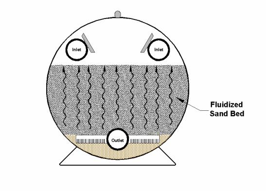
The pressure in the filter will increase and the flow of water through the filter will diminish as dirt accumulates in the filter. Eventually, the filter will become obstructed enough with dirt that it will become necessary to backwash the filter.
Please note that a filter removes suspended matter but it does not sanitize the pool. The pool water must be sanitized and the water must be chemically balanced for optimum water clarity. Your filtration system should be designed to meet your local health codes. Pool chemistry is a specialized area and you should consult your local pool service specialist for specific details.
1.2 Backwash
The basic principal of filter backwash is to reverse the flow of water through the filter. This will remove the dirt and debris trapped in the filter bed. For this principal to work properly a flow of 15-20 GPM per square foot of filter area should pass through the filter in the reverse direction. This will help to fluidize the sand bed, loosening any solids trapped or compacted in the bed, and then lifting the solids and transporting them out of the filter to waste. Usually a two to five minute backwash duration is all that is necessary to clean the filter. Please note, it is absolutely necessary to have a large enough waste line to accommodate the backwash flow rate of the filter. A 6” waste line is recommended for all THS series filter vessels.
Tank Cross Section During Backwash Mode
Tank Owner’s Manual |
Pg. 4 of 23 |
9/26/05 |
Rev. D |
2.0 Installation and Assembly
If you have purchased the vessel(s) with the optional face piping kit, please refer to documentation provided with the face piping kit.
2.1Receiving and Inspecting
•Upon receipt of filter(s), check the filter pallet(s) and auxiliary cartons for any evidence of damage due to rough handling in shipment. If the filter(s) or any filter components are damaged, NOTIFY FREIGHT CARRIER IMMEDIATELY.
•Verify that you have all equipment contained on the Packing List(s) and that there is no apparent damage to this equipment.
NOTE: BEFORE BEGINNING INSTALLATION, MAKE SURE PROPER SAFETY EQUIPMENT IS BEING USED.
2.2Locating the Filter
•Prior to installing the filter(s), be sure to provide a PERMANENT LEVEL SLAB on which to mount the filter. Preferably the slab should consist of reinforced concrete poured in a form. Alternately, the filter(s) can be mounted on a platform constructed of concrete block or brick. The platform must be able to support the weight of the entire system (including media and water). DO NOT use sand to level the filter(s) or for pump mounting, as it will wash away.
•Position the concrete slab so that the instructions, warnings and the pressure gauges on the system will be visible to the operator. It should be positioned so that the piping connections, manway, and drain are convenient and accessible for servicing and winterizing. If possible, ensure that the filter(s) are positioned to accommodate any rough plumbing that may have been previously installed. Dimensions ‘A’ and ‘B’ in Figure 1 (next page) give the minimum filter to wall clearance in order to maintain a 6” minimum clearance between the tank and the wall (or other equipment). These are only given as minimum distance guidelines. Tanks may be set up at larger clearances if desired.
IMPORTANT: If a pre-glued diaphragm valve face piping kit has been purchased, it is very important that the center to center (“C-C”) of the tanks be held to the dimension listed in Figure 1. Failure to do so may cause the piping kit not to fit properly.
Tank Owner’s Manual |
Pg. 5 of 23 |
9/26/05 |
Rev. D |
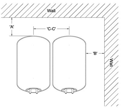
Figure 1
Model |
"A" |
"B" |
"C-C" |
|
(in.) |
(in.) |
(in.) |
||
|
||||
|
|
|
|
|
THS3461 |
|
|
39 |
|
|
|
|
||
THS3484 |
|
|
||
|
|
|
||
|
|
|
|
|
THS4272 |
6 |
6 |
|
|
|
|
|
46 1/4 |
|
THS4284 |
|
|
||
|
|
|
|
|
THS4296 |
|
|
|
|
|
|
|
|
•Ensure that the tank(s) are level, both across each pipe connection and from the influent pipe to the effluent pipe. For two tank systems, make sure the tanks are level to each other. If adjustments need to be made, loosen the nut underneath the saddles and adjust the saddle placement as needed. Be sure to tighten the nut after adjustment. If shimming is required to raise one end of the tank, be sure to use a non-compressible material placed under the bottom of the tank saddle.
2.3Setting Anchor Bolts
NOTE: Local, county, and state codes may require that the tanks be anchored in a specific way. Please verify before proceeding with anchor installation.
•If the tanks are to be anchored to the slab, mark the holes when the tanks are in their desired position on the slab. Install anchors per manufacturer’s specifications.
NOTE: Move the tanks aside before drilling for anchors. This may be necessary in order to comply with the anchor manufacturer’s instructions, and will avoid damage to the tanks and/or saddles during anchor installation.
Tank Owner’s Manual |
Pg. 6 of 23 |
9/26/05 |
Rev. D |
2.4 Install All Piping
NOTE: Unless the optional piping kit was purchased from the filter manufacturer, which provides the valves and piping to facilitate proper backwash and filtration operation, the filter manufacturer cannot accept responsibility for the design, installation, and operation of same. If an optional face piping kit was purchased, please refer to the appropriate manual provided with the kit for installation instructions.
•Install all piping to provide proper filtration and backwash operation. We recommend dry fitting all piping to ensure the proper fit.
•The influent/effluent piping on the tanks are supplied with grooves for grooved coupling connections. If a flanged connection is desired, a flange can be solvent welded to the pipe on the tank. Use a PVC cement which has been NSF approved for potable water applications. Apply according to manufacturer’s instructions. Please note, certain modifications to the tank may void the manufacturer’s warranty. Please contact manufacturer before proceeding with any modifications.
•Once installed, all piping must be fully supported with bracing and hangers (by others) to prevent damage to the system from weight and vibration.
2.5Inspection of Components
Before performing the initial start up of the filter system, inspect the tanks and components to ensure that no damage has occurred during the shipment of the vessel.
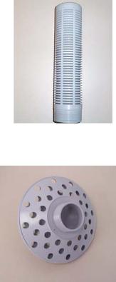
•Check for loose, damaged, and missing laterals. If they are loose, tighten them to hand tight, making sure that the slots are facing down. Missing or damaged laterals can result in returning the sand media from the filters to the pool, and must be replaced.
Lateral
•Check for loose, damaged, and missing diffusers.
These are a key component in flow distribution in the tank. If they are loose, tighten them to hand tight. Missing or damaged diffusers should be replaced.
Diffuser
Tank Owner’s Manual |
Pg. 7 of 23 |
9/26/05 |
Rev. D |
 Loading...