


1 1
MiniMax® NT Low NOx Series
POOL & SPA HEATERS
OPERATION & INSTALLATION MANUAL
 WARNING
FOR YOUR SAFETY - READ BEFORE OPERATING Warning: If you do not follow these instructions exactly, a fire or explosion may
result, causing property damage, personal injury or loss of life. For additional free copies of this manual; call (800) 831-7133.
To
Consumer
Retain For
Future
Reference
U.S. Patent Numbers 5,318,007 - 5,228,618 5,201,307 - 4,595,825
 WARNING
Warning: Improper installation, adjustment, alteration, service or maintenance can cause property damage, personal injury or death. Installation and service must be performed by a qualified installer, service agency or the gas supplier.
For Your
Safety
WHAT TO DO IF YOU SMELL GAS
•Do not try to light any appliance.
•Do not touch any electrical switch; do not use any phone in your building.
•Immediately call your gas supplier from a neighbor's phone. Follow the gas supplier's instructions.
•If you cannot reach your gas supplier, call the fire department.
Do not store or use gasoline or other flammable vapors and liquids in the vicinity of this or other appliances.
|
|
Pentair Pool Products, Inc. |
|
|
|
1620 Hawkins Ave., Sanford, NC 27330 • (919) 774-4151 |
|
|
|
10951 W. Los Angeles Ave., Moorpark, CA 93021 • (805) 523-2400 |
|
|
|
|
|
Rev. C 11-1-01 |
P/N 471593 |
||
|
2 |
Table of Contents |
|
Introduction ............................................................................................................... |
3 |
Important Notices ...................................................................................................................................................................... |
3 |
Code Requirements ................................................................................................................................................................... |
3 |
Warranty Information ................................................................................................................................................................. |
4 |
Operation .................................................................................................................... |
4 |
Safety Rules .............................................................................................................................................................................. |
4 |
HSI (Hot-Surface Ignition) Lighting/Operation - Natural Gas ..................................................................................................... |
5 |
Installation Instructions—Specifications................................................................. |
6 |
Installation — Electrical ............................................................................................................................................................. |
7 |
Installation — Remotes (2 and 3 Wire) ...................................................................................................................................... |
8 - 9 |
Installation — Wiring Diagram ................................................................................................................................................... |
10 - 12 |
Installation — Water Connections .............................................................................................................................................. |
13 |
Installation — Plumbing ............................................................................................................................................................. |
13 |
Installation — Gas Line ............................................................................................................................................................. |
14 |
Pipe Sizing Chart/Gas Pressure Requirements ......................................................................................................................... |
14 |
Regulated Manifold Pressure Test ............................................................................................................................................. |
14 |
Venting — Indoor Installations ................................................................................................................................................... |
15 - 18 |
Venting — Outdoor Installations ................................................................................................................................................ |
19 |
Basic Operation — General Description .................................................................................................................................... |
20 |
Basic Operation — Safety Controls ........................................................................................................................................... |
21 - 22 |
Basic Operation — HSI Ignition Module .................................................................................................................................... |
22 |
Thermostat (Programming & Layout) ........................................................................................................................................ |
23 |
Temperature & Time Setting (Programming) ............................................................................................................................. |
24 - 25 |
Maintenance ............................................................................................................................ |
26 |
Maintenance Instructions ........................................................................................................................................................... |
26 |
Pressure Relief Valve ................................................................................................................................................................ |
26 |
Maintenance (Water Treatment) ................................................................................................................................................ |
27 |
Trouble Shooting ....................................................................................................... |
28 |
Normal Operation Sequence ..................................................................................................................................................... |
28 - 29 |
Troubleshooting & Service ......................................................................................................................................................... |
30 - 31 |
Troubleshooting (General) ......................................................................................................................................................... |
32 |
MiniMax NT Low NOx Parts List & Exploded View (Single Voltage) ......................................... |
33-34 |
MiniMax NT Low NOx Parts List & Exploded View (Dual Voltage)............................................ |
35-36 |
Warranty Information ................................................................................................. |
Back Cover |
P/N 471593 |
Rev. C 11-1-01 |

3
Introduction
MiniMax NT Low NOx
Pool and Spa Heaters
Congratulations on your purchase of a MiniMax NT Low NOx high performance heating system. Proper installation and service of your new heating system and correct chemical maintenance of the water will ensure years of enjoyment. The MiniMax NT Low NOx is a compact, lightweight, efficient, induced-draft, gas fired high performance pool and spa heater that can be directly connected to schedule 40 PVC pipe. The MiniMax NT Low NOx, also comes equipped with the Pentair multifunction temperature controller 7800 which shows, at a glance, the proper functioning of the heater. All HSI (hot-surface ignition) MiniMax NT Low NOx heaters are designed with a direct ignition device (HSI) which eliminates the need for a standing pilot. The MiniMax NT Low NOx requires an external power source (120/240 VAC 50/60 Hz) to operate.
IMPORTANT NOTICES
...For the installer and operator of the MiniMax NT Low NOx pool and spa heater. The manufacturer’s warranty may be void if, for any reason, the heater is improperly installed and/or operated. Be sure to follow the instructions set forth in this manual. If you need any more information, or if you have any questions regarding to this pool heater, please contact Pentair Pool Products, Inc. at (800) 831-7133.
These heaters are designed for the heating of swimming pools and spas, and should never be employed for use as space heating boilers, general purpose water heaters, in non-stationary installations, or for the heating of salt water.
Do not use the heater to protect pools or spas from freezing if the final maintenance temperature desired is below 60° F. as this will cause condensation related problems.
CODE REQUIREMENTS
The installation must conform with local codes or in the absence of local codes with the latest National Fuel Gas Code, ANSI Z223.1, and the latest edition of the National Electrical Code, NFPA 70.
Installation in Canada to be made in accordance with the latest CAN/CGA-B149.1 or .2 and CSA C22.1 Canadian Electric Code, part 1.
Rev. C 11-1-01 |
|
P/N 471593 |
|
Operation |
4 |
|
|
This instruction manual provides operating instructions, installation and service information for the MiniMax NT Low NOx high performance heater. The information in this manual applies to the MiniMax NT Low NOx 200, 250, 300, and 400 natural gas models.
It is very important that the owner/installer read and understand the section covering installation instructions, and recognize the local and state codes before installing the MiniMax NT Low NOx. History and experience has shown that most heater damage is caused by improper installation practices.
WARRANTY INFORMATION
The MiniMax NT Low NOx pool heater is sold with a limited factory warranty. Specific details are described on the back cover of this manual and a copy of the warranty and warranty registration card are included with the product. Return the warranty registration card after filling in the serial number from the rating plate inside the heater.
Pentair Pool Products’ high standards of excellence include a policy of continuous product improvement resulting in your state-of-the-art heater. We reserve the right to make improvements which change the specifications of the heater without incurring an obligation to update the current heater equipment.
Operation


 SAFETY RULES
1.Spa or hot tub water temperatures should never exceed 104° F. A temperature of 100° F. is considered safe for a healthy adult. Special caution is suggested for young children.
2.Drinking of alcoholic beverages before or during spa or hot tub use can cause drowsiness which could lead to unconsciousness and subsequently result in drowning.
3.Pregnant women beware! Soaking in water above 100° F. can cause fetal damage during the first three months of pregnancy (resulting in the birth of a brain-damaged or deformed child). Pregnant women should stick to the 100° F. maximum rule.
4.Before entering the spa or hot tub, the user should check the water temperature with an accurate thermometer. Spa or hot tub thermostats may err in regulating water temperatures by as much as 4° F.
5.Persons with a medical history of heart disease, circulatory problems, diabetes or blood pressure problems should obtain their physician's advice before using spas or hot tubs.
6.Persons taking medication which induce drowsiness, such as tranquilizers, antihistamines or anticoagulants should not use spas or hot tubs.
 WARNING
Should overheating occur or the gas supply fail to shut off, turn off the manual gas control valve to the appliance. Do not use this heater if any part has been under water. Immediately call a qualified service technician to inspect the heater and to replace any part of control system and gas control which has been under water.
P/N 471593 |
Rev. C 11-1-01 |
Operation (Lighting) |
5 |
|
|
MINIMAX NT LOW NOx HSI ELECTRONIC IGNITION LIGHTING/OPERATION - NATURAL GAS
FOR YOUR SAFETY: READ BEFORE LIGHTING
 WARNING
If you do not follow these instructions exactly, a fire or explosion may result causing personal injury, loss of life and property damage.
Do not attempt to light the heater if you suspect a natural gas leak. Lighting the heater can result in a fire or explosion which can cause personal injury, death, and property damage.
A.This heater is equipped with an ignition device which automatically lights the main burners. Do not try to light the burners by hand.
B.BEFORE OPERATING, smell all around the heater area for gas. Be sure to smell next to the floor because some gas is heavier than air and will settle on the floor.
WHAT TO DO IF YOU SMELL GAS
-Do not try to light any heater.
-Do not touch any electrical switch; do not use any phone in your building.
-Immediately call your gas supplier from a neighbor's phone. Follow the gas supplier's instructions.
-If you cannot reach your gas supplier, call the Fire Department.
C.Use only your hand to push in or turn the gas control knob. Never use tools. If the knob will not push in or turn by hand, don't try to repair it. Call a qualified service technician. Forced or attempted repair may result in a fire or explosion.
D.Do not use this heater if any part has been under water. Immediately call a qualified service technician to inspect the heater and to replace any part of the control system and any gas control which has been under water.
E.The MiniMax NT Low NOx incorporates the Pentair temperature controller 7800 to aid you in the operation of the heater, and to assist in diagnosing a failure in the heater’s function.
OPERATING INSTRUCTIONS
1. STOP! Read the safety information above.
2.Set the thermostat to the lowest setting.
3.Turn off electric power to the heater.
4.This heater is equipped with an ignition device which automatically lights main burners. Do not try to light the burners by hand.
5.Remove the control access door.
6.Push in gas control knob slightly and turn clockwise to “OFF”. (If not on “OFF” position.)
7.Wait five (5) minutes to clear out any gas. If you then smell gas, STOP! Follow "B" in the safety information above. If you don't smell gas, go to the next step.
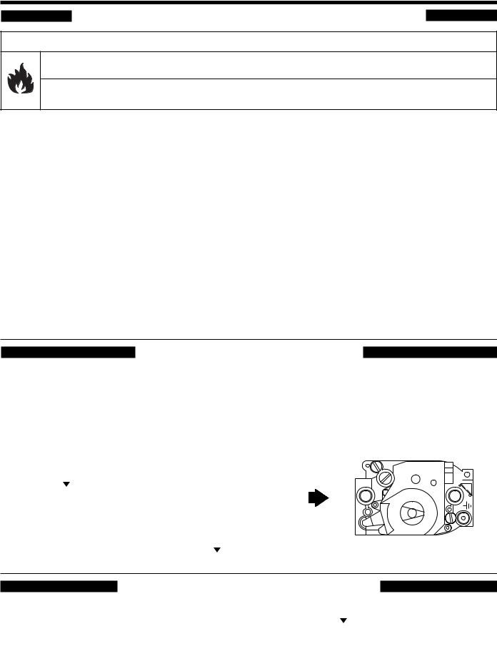
8.Turn knob on gas control counterclockwise  to “ON”; see Figure 1.
9.Replace the control access door.
10.Turn on the electrical power to the heater.
11.Set the thermostat to the desired setting.
12.If the heater will not operate, follow the instructions "To Turn Off Gas To Heater" and call your service technician or gas supplier.
Gas
Inlet
ON
OFF
Figure 1. Gas control knob shown in “ON” position.
TO TURN OFF GAS TO APPLIANCE
1.Set the thermostat to lowest setting.
2.Turn off all electric power to the heater if service is to be performed.
3.Remove control access door.
4.Push in gas control knob slightly and turn clockwise  to "OFF". Do not force.
5.Replace control access door.
Rev. C 11-1-01 |
P/N 471593 |
6
Installation Instructions
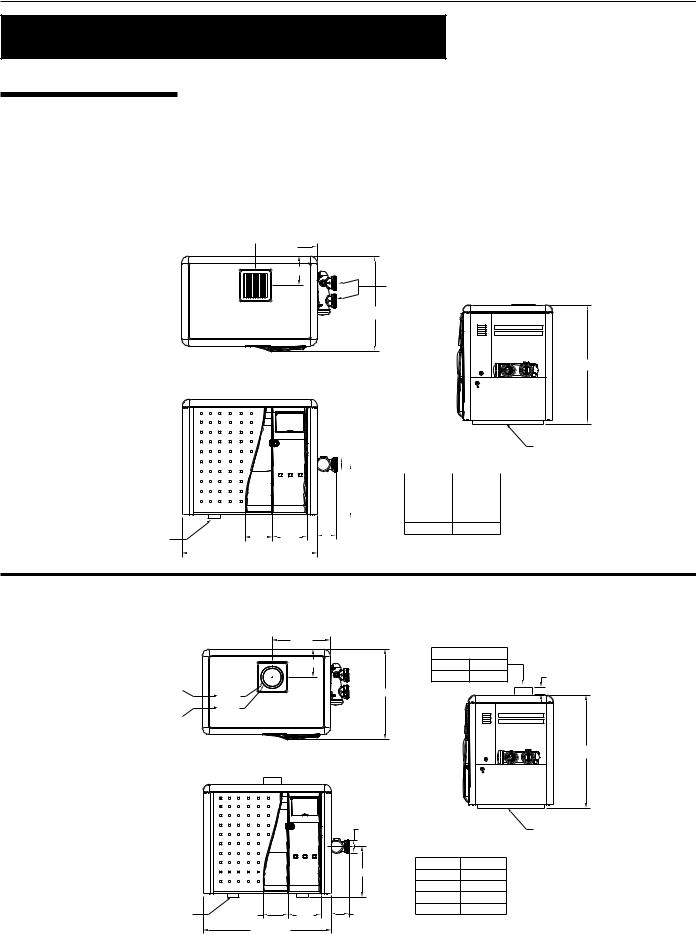
SPECIFICATIONS
IMPORTANT NOTICE: These installation instructions are designed for use by qualified personnel only, trained especially for installation of this type of heating equipment and related components. Some states require installation and repair by licensed personnel. If this applies in your state, be sure your contractor bears the appropriate license.
OUTDOOR VENTILATION
Figure 2.
 15.50
15.50
7.35
2 in. SOCKET
24.05
30.63
|
|
|
|
|
3.50 |
|
|
LEG |
|||
|
|
|
|
|
|
|
|
|
|
|
|
|
|
|
|
|
|
|
|
|
|
|
|
|
|
|
|
|
|
|
|
|
|
|
|
|
|
|
|
|
|
|
|
|
MODEL |
"A" DIM. |
|
|
|
14.50 |
200 |
21.63 |
|
||||||
|
|
|
|
|
|
|
|
|
250 |
24.63 |
|
|
|
|
|
|
|
|
|
|
|
|
|
|
|
|
|
|
|
|
|
|
300 |
27.63 |
|
400 34.13
LEG |
6.64 |
|
|
|
8.84 |
|
|
|
|
4.875 |
||
|
|
|
|
|
||||||||
|
|
|
|
|
|
|
|
|
|
|
|
|
|
|
|
"A" DIM. |
|
|
|
|
|
|
|||
|
|
|
|
|
|
|
|
|
||||
Figure 3.
INDOOR VENTILATION
|
15.50 |
|
|
|
|
|
INDOOR VENT ADAPTOR |
|
|
|
7.35 |
P/N 460506 |
4 in. Kit |
|
|
|
P/N 460507 |
5 in. Kit |
2.00 |
4 in. Kit |
Ø4.88 |
24.05 |
|
|
P/N 460506 |
|
|
|
|
|
Ø5.88 |
|
|
|
5 in. Kit |
|
|
|
|
P/N 460507 |
|
|
|
|
30.63
|
|
|
3.50 |
|
LEG |
|
|
|
14.50 |
MODEL |
"A" DIM. |
|
|
|
200 |
21.63 |
|
|
|
|
|
||
|
|
|
|
250 |
24.63 |
|
|
|
|
300 |
27.63 |
LEG |
6.64 |
8.84 |
4.875 |
400 |
34.13 |
|
|
||||
|
|
"A" DIM. |
|
|
|
P/N 471593 |
Rev. C 11-1-01 |
Installation (Electrical) |
7 |
|
|
ELECTRICAL, ALL HSI UNITS
Electrical Rating 50/60 Hz 120 V.A.C. ONLY
NOTE
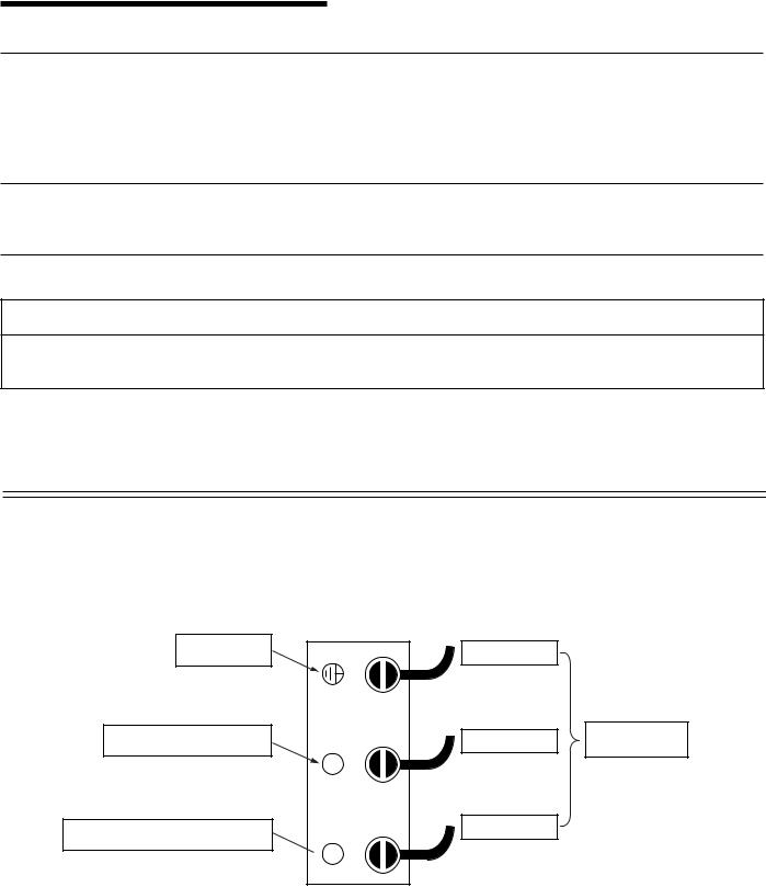
The transformer is pre-wired at the factory for 120 VAC operation ,connect line supply to the line terminal block inside junction box. Use caution in connecting supply to proper Line (L), Neutral (N), and Ground (GND) terminals; see below, Figure 5.
NOTE
If any of the original wiring supplied with this heater must be replaced, installer must supply (No. 18 AWG 105° C. U.L. approved AWM low energy stranded) copper wire or it’s equivalent.
In Canada: wires must be CSA approved.
WARNING
The heater must be electrically grounded and bonded in accordance with local codes or, in the absence of local codes, with the latest national electrical codes ANSI/NFPA No. 70.
In Canada: CSA standard C22.1 Canada Electrical Code Part 1 and/or local codes.
Always use crimp type connectors when connecting two wires.
LINE TERMINAL BLOCK
GROUND |
GREEN WIRE |
|
CONNECTION |
||
|
NEUTRAL / WHITE 120 VAC |
WHITE WIRE |
INTERNAL |
|
FACTORY WIRES |
|||
|
N |
||
|
|
BLACK WIRE
POSITIVE LINE FOR 120 VOLTS AC
L
Figure 5.
Rev. C 11-1-01 |
P/N 471593 |
Installation (Remotes) |
8 |
|
|
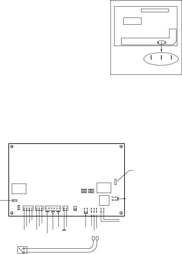
TWO-WIRE OR THREE-WIRE REMOTE HOOK-UP
Before connecting the remote control system please read the following:
1.First turn the gas valve to the "OFF" position and power up the heater, now using the front buttons on the temperature controller, set the "SPA" and "POOL" temperature to the maximum setting, see Page 24.
2.Now turn the heater to the "OFF" mode by using the "OFF" button on the temperature controller, see Page 24 or by using the main power switch located on the bottom of the junction box.
3.With the heater in the "OFF" mode, locate the three tabs on the back of the temperature controller as viewed from the backside,
see Figure 6.
4.• Two-wire remote with temperature control:
1 |
2 |
3 |
POOL |
SPA |
GND |
Figure 6. |
|
|
a)Using 3/16" female quick disconnect connectors, connect one wire to the "GND" tab of the temperature controller, then the second wire to either the "SPA" or "POOL" tab.
b)Now return power to the heater but leaving the temperature controller in the "OFF" position,
see Page 24. (Note: If you used the main power switch to turn off the heater, now turn the main power switch on.) At this time the remote system has control over the heater, and will turn it on and off when called for by the remote system thermostat thus keep the pool and spa at the desired temperature.
2 WIRE REMOTE
5 A
25O V RELAY
TEMPERATURE |
1 |
2 3 |
DISPLAY MODE |
C |
F |
|
IGN MODULE G VALVE
3
2 1 2 3 4 1 2 3
1
VAC |
PV |
PV/MV MV |
PV/MV |
MV |
24 |
|
|
PV |
|
|
|
|
|
|
|
|
|
|
|
|
|
|
|
|
|
|
|
5 A FUSE |
|
|
|
|
|
|
|
|
|
|
|
|
|
|
|
|
|
|
FOR AUX2 (PILOT DUTY ONLY) |
|
|
|
|
|
|
|
|
|
|
|
|
|
|
|
|
AUX2 |
|
|
|
|
|
|
|
|
|
|
|
PURGE |
PUMP |
|
10 A |
|
|
||||
|
|
|
|
|
|
|
|
|
MODE |
|
25O V |
|
|
|||||
|
|
|
|
|
|
|
|
|
5 |
3 |
1 |
5 |
3 |
1 |
|
RELAY |
|
|
|
|
|
|
|
|
|
|
|
J1 |
|
|
|
|
|
J2 |
PUMP/AUX2 |
|
|
|
|
|
|
|
|
|
|
|
6 |
4 |
2 |
6 |
4 |
2 |
|
|
|
|
|
|
|
|
|
|
|
|
|
|
|
|
|
|
|
|
10 A |
4 |
A.C LOAD (PUMP/AUX2) |
|
|
|
|
|
|
|
|
|
|
|
|
|
|
|
|
25O V |
3 |
(PILOT DUTY ONLY) }NOT USED |
|
|
|
|
|
|
|
|
|
|
|
|
|
|
|
|
RELAY |
||
|
|
|
|
|
|
|
|
|
|
|
|
|
|
|
|
|
|
|
|
|
LIMITS |
|
|
POWER |
TPROBE |
|
|
|
REMOTE |
BLOWER |
|
|
|||||
|
|
|
|
|
|
|
(AUX1) |
|
|
|
||||||||
1 |
2 |
3 |
4 |
5 |
6 |
1 |
2 |
1 |
2 |
|
|
|
|
|
|
|||
|
|
|
|
|
|
|
|
|
||||||||||
FUSE |
|
LIMITH |
|
PRESS |
|
|
VAC24 |
|
|
PRESSAIR |
|
|
1 |
2 |
3 |
|
|
|
|
|
|
|
|
|
|
POOL |
SPA |
GND |
|
|
BLOWER (POWER) LINE |
||||||
|
|
|
|
|
|
|
|
|
|
|
|
|
|
|
|
|
|
BLOWER (POWER) LINE |
T |
|
|
|
|
|
|
|
|
|
|
|
|
|
SPA |
GND |
|
|
|
REMOTE SWITCH CONTROLLER
Figure 7.
Three-Wire continued on next page.
P/N 471593 |
Rev. C 11-1-01 |
Installation (Remotes) |
9 |
|
|
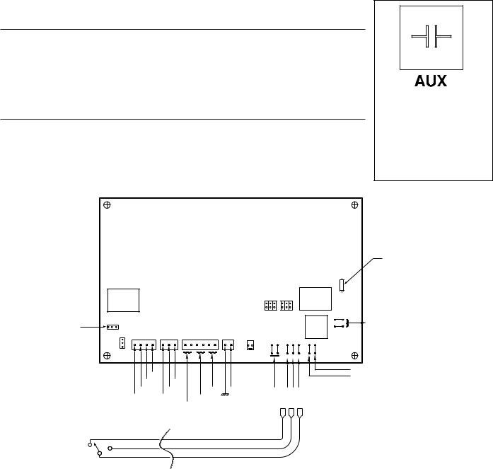
TWO-WIRE OR THREE-WIRE REMOTE HOOK-UP, (cont’d.)
• Three-wire remote:
a)Using 3/16" female quick disconnect connectors, connect the common wire to the "GND" tab of the temperature controller, then connect the two remaining wires to the temperature controller corresponding to the remote control device, pool wire to "POOL" tab, spa wire to "SPA" tab.
b)Now return power to the heater. (Note: If you used the main power switch to turn off the heater, now turn the main power switch on.) At this time, the remote system has control over the heater and if pool or spa temperature is below the temperature controller setting, then the heater will try to come on.
c)If you desire to reset the temperature settings of the temperature controller, the remote has to be in the desired mode for you to change the particular setting. Example: You wish to raise or lower the pool temperature from the factory setting, you must have the remote system in the pool mode, if you wish to change the spa temperature, you must have the remote system in the spa mode.
5.Now turn on the gas valve to "OPEN" position, the heater is now ready to operate.
NOTE
The heater factory settings are 78° F. for the pool and 104° F. for the spa. When connecting a remote control to the MiniMax, you must install the low voltage thermostat wires in separate conduit from ANY line voltage wires. Failure to follow these instructions will cause the thermostat relay to react erratically. A Remote hook-up deactivates the selector keys on the front thermostat display panel and gives selection control to the remote.
3 WIRE REMOTE
This icon is not a fault icon but instead indicates a remote switching device is connected to the Pentair Temperature Controller 7800, and has overriding selection control of Pentair Temperature Controller 7800.
5 A FUSE
FOR AUX2 (PILOT DUTY ONLY)
AUX2
|
|
|
|
|
|
|
|
|
|
|
|
|
|
|
|
|
|
|
|
|
|
PUMP |
|
10 A |
||
|
|
5 A |
|
|
|
|
|
|
|
|
|
|
|
|
|
|
|
|
PURGE MODE |
|
25O V |
|||||
|
|
25O V |
|
|
|
|
|
|
|
|
|
|
|
|
|
|
|
|
5 |
3 |
1 |
5 |
3 |
1 |
|
RELAY |
|
|
RELAY |
|
|
|
|
|
|
|
|
|
|
|
|
|
|
|
J1 |
|
|
|
|
|
J2 |
PUMP/AUX2 |
|
|
|
|
|
|
|
|
|
|
|
|
|
|
|
|
|
|
|
|
|
|
|
|
|
|
|
|
|
|
|
|
|
|
|
|
|
|
|
|
|
|
|
|
|
|
|
6 |
4 |
2 |
6 |
4 |
2 |
|
|
|
|
|
|
|
|
|
|
|
|
|
|
|
|
|
|
|
|
|
|
|
|
|
|
|
|
10 A |
TEMPERATURE |
1 2 |
3 |
|
|
|
|
|
|
|
|
|
|
|
|
|
|
|
|
|
|
|
|
|
|
|
25O V |
|
|
|
|
|
|
|
|
|
|
|
|
|
|
|
|
|
|
|
|
|
|
|
|
|
RELAY |
|
DISPLAY MODE |
C |
F |
|
|
|
|
|
|
|
|
|
|
|
|
|
|
|
|
|
|
|
|
|
|
|
|
|
|
|
|
|
|
|
|
|
|
|
|
|
|
|
|
|
|
|
|
|
REMOTE BLOWER |
|||||
|
|
|
IGN MODULE |
G VALVE |
|
|
LIMITS |
|
|
POWER TPROBE |
|
|
|
|||||||||||||
|
|
3 |
|
|
|
|
|
|
|
(AUX1) |
|
|||||||||||||||
|
|
1 |
2 |
3 |
4 |
1 |
2 |
3 |
1 |
2 |
3 |
4 |
5 |
6 |
1 |
2 |
|
|
|
|
|
|
||||
|
|
2 |
1 |
2 |
|
|
|
|
|
|
|
|||||||||||||||
|
|
|
|
|
|
|
|
|
|
|
|
|
|
|
|
|
|
|
|
|
|
|
|
|||
|
|
1 |
|
|
|
|
|
|
|
|
|
|
|
|
|
|
|
|
|
|
|
|
|
|
|
|
|
|
|
|
|
|
|
|
|
|
|
|
|
|
|
|
|
|
|
|
AIR PRESS |
|
|
1 |
2 |
3 |
|
|
|
|
24VAC |
PV |
PV/MV |
MV |
PV |
PV/MV |
MV |
FUSET |
|
HLIMIT |
|
PRESS |
|
|
24 VAC |
|
|
|
POOL |
|
SPA |
GND GND |
|
|
|
|
|
|
|
|
|
|
|
|
|
|
|
|
|
|
|
|
|
|
|
|
POOL |
SPA |
|
|
|
|
|
REMOTE POOL/OFF/SPA |
|
|
|
|
|
|
|
|
|
|
|
|
|
|
|
|
|
|
|
|||||
|
THERMOSTAT SELECT SWITCH |
|
|
|
|
|
|
|
|
|
|
|
|
|
|
|
|
|
|
|||||||
|
POOL |
|
|
|
|
|
|
|
|
|
|
|
|
|
|
|
|
|
|
|
|
|
|
|
|
|
|
SPA |
|
|
|
|
|
|
|
|
|
|
|
|
|
|
|
|
|
|
|
|
|
|
|
|
|
4 |
A.C LOAD (PUMP/AUX2) |
}NOT USED |
3 |
(PILOT DUTY ONLY) |
BLOWER (POWER) LINE
BLOWER (POWER) LINE
Figure 8.
COMMON
Rev. C 11-1-01 |
P/N 471593 |

471593 P/N
EXTERNAL
BOND LUG TERMINATE SUPPLY SAFETY GROUND WIRE (GREEN) HERE
GROUND SCREW WITH PAINT CUTTING WASHER
CHASSIS
SHEET METAL
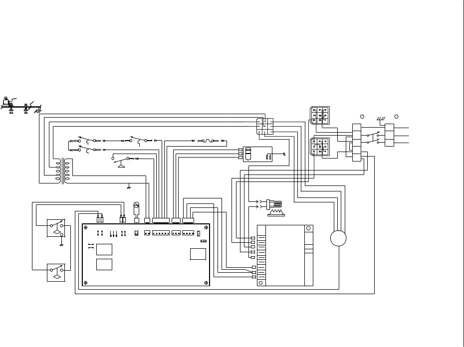
MiniMax NT 400 LOW NOx WIRING DIAGRAM
IF ORIGINAL FACTORY WIRING MUST BE REPLACED, INSTALLER MUST SUPPLY
UL OR CSA (IF CANADA) APPROVED WIRE, 18 GAUGE, 600V, 105 C TEMPERATURE RATING. THERMAL FUSE WIRING MUST BE REPLACED WITH UL OR CSA (IF CANADA) APPROVED WIRE, 18 GAUGE, 600V, 125 C TEMPERATURE RATING.
INTERCONNECTING WIRING TO APPLIANCE MUST CONFORM TO THE NATIONAL ELECTRICAL CODE OR SUPERCEDING LOCAL (WIRING) CODES.
TERM
BLOCK B
1
TERM BLOCK A
1 GRN
|
|
|
HIGH LIMIT |
|
|
EXHAUST HIGH LIMIT |
|
|
|
|
|
|
|
|
|
|
|
2 |
|
|
2 |
NEU |
|
|||
|
|
|
|
|
THERMAL SWITCHES |
|
|
|
|
|
|
|
|
|
THERMAL FUSE |
|
|
|
||||||||
|
|
|
THERMAL SWITCHES |
|
|
|
|
|
|
|
|
|
|
|
|
SUPPLY 120 VAC |
||||||||||
|
|
|
|
|
|
|
|
|
|
|
|
|
|
|
|
|
F1 |
F2 |
|
|
|
|
|
|||
|
|
|
|
|
|
|
|
|
|
RED |
|
|
|
|
|
|
WHT |
|
|
|
|
|
||||
|
|
|
|
|
|
|
|
|
|
|
|
|
|
|
|
3 |
|
|
3 |
HOT |
(ONLY) |
|||||
|
|
|
|
|
|
|
|
|
|
|
|
|
|
|
|
|
|
|
|
|||||||
|
|
|
|
|
|
|
|
|
|
|
|
|
|
|
|
|
|
|
|
|
|
|
||||
|
|
RED |
|
|
|
|
|
|
|
|
|
|
|
|
|
|
WHT |
|
GAS VALVE |
|
|
|
|
|
||
|
|
|
|
|
|
|
|
|
|
|
|
|
|
|
|
RED |
|
|
|
|
|
|
||||
|
|
|
|
|
|
|
|
|
RED |
|
|
|
|
|
|
|
|
|
4 |
|
BLK |
(HOT) |
||||
|
|
|
|
|
|
|
|
|
|
|
|
|
|
|
|
|
|
|
|
WHT |
GRN |
|
||||
|
|
|
|
|
|
|
|
|
|
|
|
|
|
|
|
|
|
|
|
|
|
|
|
|
||
FROM |
|
HOT |
W1 |
|
|
|
|
|
WHT |
|
|
|
|
|
|
|
|
|
|
BLU |
5 |
|
|
|
|
|
|
|
|
|
|
|
|
|
|
|
|
|
|
|
|
|
|
|
|
|
|
|
|
||||
TERM |
B |
|
|
|
|
|
W2 |
WHT |
|
|
|
|
|
|
|
|
|
|
|
WHT |
|
|
|
|
|
|
BLOCK |
|
|
|
|
|
|
|
|
|
|
|
|
|
|
|
|
WHT |
|
|
(NEU) |
|
|
|
|||
|
|
|
|
|
|
|
|
|
|
|
|
|
|
|
|
|
|
|
|
|
|
|
|
|||
|
|
|
|
|
|
|
|
|
|
|
|
|
|
|
|
|
|
|
|
|
|
|
|
|
|
|
|
|
120 VAC |
|
|
|
|
|
|
|
|
|
|
|
|
|
|
|
|
FC |
24VAC |
(HOT) |
|
WHT |
|
|
|
|
|
|
WATER PRESSURE |
|
|
|
|
|
|
|
|
|
|
|
|
RED |
RET |
|
|
|
|
|||||
|
|
(ONLY) |
|
|
|
|
|
|
|
|
|
|
|
|
|
FL |
|
|
|
|
|
|
||||
|
|
|
|
SWITCH |
ORG |
|
|
|
|
|
|
|
|
|
|
|
BLK |
|
|
|
|
|
|
|
||
|
|
|
|
|
|
|
|
|
|
|
|
|
|
|
|
|
|
FH |
|
|
|
|
|
|
|
|
|
|
|
|
|
|
|
|
|
|
|
|
|
|
|
|
|
|
ORG |
|
|
|
|
|
|
|
|
|
|
|
|
|
|
|
|
|
|
|
|
|
|
|
|
|
|
|
PC |
|
|
|
|
|
|
|
FROM |
|
|
|
|
|
|
|
|
|
|
|
|
|
|
|
|
|
|
ORG |
|
|
|
|
|
|
|
|
NEU |
|
|
|
|
WHT |
|
|
|
|
|
|
|
|
|
|
|
PL |
|
|
|
|
|
|
|
|
|
|
|
|
|
|
|
|
|
|
|
|
|
|
|
|
|
FAN CON. BOARD |
|
BLK |
SPEEDHI |
SPEEDLOW |
SPEED |
|
|||
TERM |
B |
|
|
|
|
GRN |
TEMPERATURE |
|
|
|
|
|
|
|
|
|
|
|
PH |
|
|
|||||
|
|
|
|
|
|
|
|
|
|
|
|
|
|
|
|
|
|
|
|
|
|
|||||
BLOCK |
|
|
|
|
|
|
|
|
|
|
|
|
|
|
|
|
ORG |
|
|
|
|
|
|
|
||
|
|
|
|
|
|
|
|
|
|
|
|
|
|
|
|
|
|
HOT SURFACE |
|
|
|
|
|
|||
|
|
|
|
|
|
|
|
|
|
|
|
|
|
|
|
|
|
|
|
|
|
|
|
DUAL |
|
|
|
|
|
|
|
|
|
|
|
|
|
|
|
|
|
|
|
RED |
|
|
|
IGNITOR |
|
|
|
|
|
|
|
|
|
|
|
|
|
|
|
|
|
|
|
|
|
|
|
|
|
|
|
|
|
|
|
|
|
|
|
|
|
|
|
PROBE |
|
|
|
|
|
|
|
|
|
WHT |
|
|
|
HOT SURFACE |
|
|
|
FAN |
|
|
|
|
|
|
|
|
|
|
|
|
|
|
|
|
|
|
|
|
|
|
|
|
|
|||
|
|
|
|
|
|
|
|
|
|
|
|
|
|
|
|
|
BLU |
|
|
|
|
|
|
|
|
|
|
|
|
BLK |
|
|
|
|
|
|
|
|
|
|
|
|
|
|
|
|
IGNITOR |
|
|
|
|
|
|
ORG |
|
|
|
|
|
|
|
|
|
|
|
|
|
|
ORG |
|
|
|
|
|
|
|
|
|
||
ORG |
|
|
|
|
|
|
|
|
|
|
|
|
|
|
|
|
|
|
|
|
|
|
|
|||
|
|
|
|
|
|
|
|
|
|
|
|
|
|
|
|
|
|
|
|
|
|
|
|
|||
|
|
|
|
|
|
|
2 |
1 |
2 3 4 5 6 |
1 |
|
1 2 3 |
4 |
3 |
1 2 |
|
|
|
|
|
|
|
|
|
||
|
|
|
BLK |
|
|
|
|
|
|
|
|
|
|
|
|
|
|
|||||||||
|
|
|
|
|
|
|
|
|
|
|
|
|
|
|
|
|
|
|
|
|
|
|
|
|
|
|
|
|
|
|
|
|
|
|
P4 |
P7 |
|
|
P10 |
|
P11 |
|
|
|
|
|
BURNER |
BLK |
|
|
|
|
|
|
|
|
|
|
|
|
|
|
|
|
|
|
|
|
|
|
|
|
|
|
WHT |
|
COM |
|
|
|
|
LOW AIR PRES. |
|
|
REMOTE |
AIR PR SW. |
|
2 1 6 5 4 3 2 1 |
3 |
2 1 |
4 |
3 2 |
1 |
2 |
|
|
|
|
|
|
|
||||||
|
|
BLOWER |
TPROBE |
POWER |
LIMITS |
|
G VALVE |
IGN MODULE |
|
|
|
|
|
|
|
|
|
|
||||||||
|
|
SWITCH |
|
|
|
|
|
|
|
|
|
|
|
|
|
|
1 |
|
|
|
ORG |
|
|
|
|
|
|
|
|
|
|
COM SPA POOL |
|
|
|
|
|
|
|
|
|
|
|
3 |
|
|
|
|
|
|
|
|
|
|
|
|
|
|
|
|
|
|
|
|
|
|
|
|
|
F |
|
C |
|
|
|
|
|
|
||
ORG |
ORG |
1 |
|
|
|
|
|
|
|
|
|
|
|
|
|
3 |
2 |
1 |
|
S1 |
|
|
|
|
|
|
|
|
|
10A |
|
|
|
|
|
|
|
|
|
|
|
|
|
|
|
|
|
|
|
||||
|
|
|
2 |
|
|
|
|
|
|
|
|
|
|
|
|
|
|
|
|
L1 |
|
WHT |
|
|
|
|
|
|
|
250V |
|
|
|
|
|
|
|
|
|
|
|
|
5A |
|
|
|
|
|
|
|
|||
|
|
|
|
|
|
|
|
|
|
|
|
|
|
|
|
|
|
|
|
|
|
|
|
|||
|
|
|
|
|
|
|
|
|
|
|
|
|
|
|
|
|
|
|
|
|
|
|
|
|
|
|
|
|
|
|
RELAY |
|
|
|
|
|
|
|
|
|
|
|
|
250V |
|
|
|
L2 |
|
|
|
|
|
|
|
|
|
|
|
|
|
|
|
|
|
|
|
|
|
|
|
|
|
N |
|
|
|
|
|
|
|
HI AIR PRES. |
|
|
|
|
|
|
|
|
|
|
|
|
|
|
RELAY |
|
|
|
S2 |
|
|
|
|
|
|
|
|
10A |
|
|
|
|
|
|
|
|
|
|
|
|
|
|
|
|
|
|
|
|
|
|
||
|
|
SWITCH |
|
|
|
|
|
|
|
|
|
|
|
|
|
|
|
|
|
|
|
|
|
|
|
|
|
|
|
250V |
|
|
|
|
|
|
|
|
|
|
|
|
|
|
|
ORG |
|
|
|
|
|
|
|
|
|
|
|
|
|
|
|
|
|
|
|
|
|
|
|
|
|
|
|
|
|
|
|
|
||
|
|
|
|
RELAY |
|
|
|
|
|
|
|
|
|
|
|
|
|
|
|
TH |
|
|
|
|
|
|
|
|
|
|
|
|
|
|
|
|
|
|
|
|
|
|
|
|
|
|
|
|
|
|
|
||
ORG |
|
|
AUX2 |
|
|
|
|
|
|
|
|
|
|
|
|
|
|
|
RED |
VAL |
|
|
|
|
|
|
|
|
|
|
|
|
|
|
|
|
|
|
|
|
|
|
|
BLU |
|
|
|
|
|
||||
|
|
|
|
|
|
|
|
|
|
|
|
|
|
|
|
|
|
|
|
|
|
|
|
|||
|
|
|
|
|
|
|
|
|
|
|
|
|
|
|
|
|
|
|
|
WHT |
GRN |
|
|
|
|
|
|
|
|
|
|
|
|
|
|
|
|
|
|
|
|
|
|
|
|
|
|
|
|
|
|
|
|
|
|
|
|
|
|
|
|
|
|
|
|
|
|
|
|
|
|
|
|
|
IGN MODULE |
BLK |
|
|
|
|
|
|
|
|
|
|
|
|
|
|
|
|
|
|
|
|
|
|
|
|
|
|
|
|
|
|
|
|
LOW GAS PRES. |
|
|
|
|
|
|
|
|
|
|
|
|
|
|
|
|
|
|
|
|
|
|
|
|
|
|
|
SWITCH |
|
|
|
|
|
|
|
|
|
|
|
|
|
|
|
|
|
|
|
|
|
|
|
|
WHT |
|
|
|
|
|
|
|
|
|
|
|
|
|
|
|
|
|
|
|
|
|
|
|
|
|
|
ORG |
|
|
|
|
|
|
|
|
|
|
|
|
|
|
|
|
|
|
|
|
|
|
|
|
|
|
01-1-11 C .Rev
NOx Low NT MiniMax VOLTAGE) (SINGLE |
Voltage (Single Installation |
HSI 400 |
Wiring) |
Diagram Wiring Ignition Electronic |
|
10
01-1-11 C .Rev
EXTERNAL BOND LUG
TERMINATE SUPPLY SAFETY GROUND WIRE (GREEN) HERE GROUND SCREW WITH PAINT CUTTING WASHER
CHASSIS
SHEET METAL
MiniMax NT 250 LOW NOx WIRING DIAGRAM
IF ORIGINAL FACTORY WIRING MUST BE REPLACED, INSTALLER MUST SUPPLY
UL OR CSA (IF CANADA) APPROVED WIRE, 18 GAUGE, 600V, 105 C TEMPERATURE RATING. THERMAL FUSE WIRING MUST BE REPLACED WITH UL OR CSA (IF CANADA) APPROVED WIRE, 18 GAUGE, 600V, 125 C TEMPERATURE RATING.
INTERCONNECTING WIRING TO APPLIANCE MUST CONFORM TO THE NATIONAL ELECTRICAL CODE OR SUPERCEDING LOCAL (WIRING) CODES.
TERM B BLOCK
1
RED
FROM HOT
TERM B
BLOCK
120 VAC (ONLY)
FROM NEU
TERM B
BLOCK
ORG
HI AIR PRES.
SWITCH
ORG
LOW GAS PRES.
SWITCH
WHT
ORG
HIGH LIMIT |
|
|
|
EXHAUST HIGH LIMIT |
|
|
|
|
|
|
|
|
|
|
|
|
|
|
|
|
|
|
|
|
THERMAL SWITCHES |
|
|
|
|
|
|
|
|
|
|
|
|
|
|
|
|
||
THERMAL SWITCHES |
|
|
|
|
|
|
|
|
|
|
|
|
|
|
|
|
|
|
|||
|
|
|
|
|
|
|
|
|
|
|
|
|
|
|
|
|
|
|
|
||
|
|
RED |
|
|
|
|
RED |
|
|
|
|
|
|
|
WHT |
|
|
|
|||
|
|
|
|
|
|
|
|
|
|
|
|
|
|
|
|
|
WHT |
|
|
|
|
|
|
|
|
|
RED |
|
|
|
|
|
|
|
|
|
|
|
|
|
|
||
|
|
|
|
WHT |
|
|
|
|
|
|
|
|
|
|
|
|
|
|
|
|
|
W1 |
|
|
|
WHT |
|
|
|
|
|
|
|
|
|
|
|
|
|
|
|
|
|
|
|
|
|
W2 |
|
|
|
|
|
|
|
|
|
|
|
|
|
|
|
|
|
|
|
WATER PRESSURE |
|
|
|
|
|
|
|
|
|
|
|
|
|
|
|
|
|
||
|
|
SWITCH |
ORG |
|
|
|
|
|
|
|
|
|
|
|
|
|
|
|
|
|
|
|
|
|
|
|
|
|
|
|
|
|
|
|
|
|
|
|
|
|
|
|
|
|
|
|
|
WHT |
|
|
|
|
|
|
|
|
|
|
|
|
|
|
|
|
|
|
|
|
|
GRN |
|
|
|
|
|
|
|
|
|
|
|
|
|
|
|
|
|
|
|
|
|
TEMPERATURE |
|
|
|
|
|
|
|
|
|
|
|
|
|
RED |
|
|
|
|
|
|
|
|
|
|
|
|
|
|
|
|
|
|
|
|
|
|
|
|
|
|
|
|
|
PROBE |
|
|
|
|
|
|
|
|
|
|
|
|
|
WHT |
|
|
|
|
|
|
|
|
|
|
|
|
|
|
|
|
|
|
|
|
|
|
|
|
|
|
|
|
|
|
|
|
|
|
|
|
|
|
|
|
|
|
|
BLU |
|
|
|
BLK |
|
|
|
|
|
|
|
|
|
|
|
|
|
|
|
|
|
ORG |
|
|
|
|
|
|
|
|
|
|
|
|
|
|
|
|
|
|
|
|
|
|
|
|
|
BLK |
|
|
|
2 |
1 |
|
2 3 4 5 6 |
1 |
|
1 2 3 |
4 |
3 |
1 2 |
|
|
|
|||||
|
|
|
|
|
|
|
|
|
|
|
|
|
|
|
|
|
|
|
|
|
|
|
|
|
|
P4 |
|
|
P7 |
|
|
|
PI0 |
|
|
P11 |
|
|
|
|
|||
|
BLOWER |
REMOTE AIR PR SW. TPROBE POWER |
|
|
LIMITS |
|
|
G VALVE |
IGN MODULE |
|
|
|
|||||||||
|
|
|
|
2 |
1 |
6 |
5 |
4 |
3 |
2 |
1 |
3 |
2 |
1 |
4 |
3 |
2 |
1 |
2 |
|
|
|
|
|
|
|
|
|
|
|
|
|
|
|
|
|
|
|
|
|
1 |
|
|
|
|
COM SPA |
POOL |
|
|
|
|
|
|
|
|
|
|
|
|
|
|
|
3 |
|
|
|
|
|
|
|
|
|
|
|
|
|
|
|
|
|
|
|
F |
|
C |
||
1 |
10A |
|
|
|
|
|
|
|
|
|
|
|
|
|
|
|
|
|
3 |
2 |
1 |
2 |
|
|
|
|
|
|
|
|
|
|
|
|
|
|
|
|
|
|
|
|
|
250V |
5A |
|
RELAY |
||
250V |
||
|
||
|
RELAY |
|
10A |
|
|
250V |
|
|
RELAY |
|
|
AUX2 |
|
2 WHT
THERMAL FUSE
F1 |
F2 |
BLK |
|
|
3 |
|
|
GAS VALVE |
|
RED |
4 |
|
WHT |
GRN |
|
BLU |
5 |
|
|
|
|
|
(HOT) |
|
N |
WHT |
HOT SURFACE
IGNITOR
BURNER
S1
L1
L2
S2
ORG
TH
RED
VAL
BLU
GRN
WHT
IGN MODULE
471593 P/N
|
TERM |
A |
|
|
|
BLOCK |
|
|
|
|
1 |
GRN |
|
|
WHT |
2 |
NEU |
|
|
|
|
|||
BLK |
|
SUPPLY 120 VAC |
||
3 |
HOT |
(ONLY) |
||
|
||||
BLK |
(HOT) |
|
||
(NEU) |
|
|
|
|
WHT |
|
|
|
|
WHT |
|
|
|
|
FAN |
|
|
||
BLK
BLK
NOx Low NT MiniMax VOLTAGE) (SINGLE |
Voltage (Single Installation |
HSI 250 |
Wiring) |
Diagram Wiring Ignition Electronic |
|
11
471593 P/N |
|
|
|
|
|
|
|
|
|
RED |
|
|
|
|
|
|
|
|
|
|
|
RED |
|
|
(BRN) |
BLK |
|
|
|
|
|
VOLTAGE) (DUAL |
MODELS)(ALLNOx Low NT MiniMax |
Wiring)Voltage (Dual Installation |
||||
|
|
|
|
|
|
|
|
|
MiniMax NT LOW NOx ALL MODELS WIRING DIAGRAM |
|
|
|
|
|
|
|
|
|
|
|||||||||||||||||||
|
|
|
|
|
|
|
|
|
IF ORIGINAL FACTORY WIRING MUST BE REPLACED, INSTALLER MUST SUPPLY |
|
|
|
|
|
|
|
|
|
||||||||||||||||||||
|
|
|
|
|
|
|
|
|
UL OR CSA (IF CANADA) APPROVED WIRE, 18 GAUGE, 600V, 105˚ C TEMPERATURE RATING. |
|
|
|
|
|
|
|||||||||||||||||||||||
|
|
|
|
|
|
|
|
|
THERMAL FUSE WIRING MUST BE REPLACED WITH UL OR CSA (IF CANADA) APPROVED |
|
|
|
|
|
|
|
||||||||||||||||||||||
|
|
|
|
|
|
|
|
|
WIRE, 18 GAUGE, 600V, 200˚ C TEMPERATURE RATING. |
|
|
|
|
|
|
|
|
|
|
|||||||||||||||||||
|
|
|
|
|
|
|
|
|
INTERCONNECTING WIRING TO APPLIANCE MUST CONFORM TO THE NATIONAL ELECTRICAL |
|
|
|
|
|
|
|||||||||||||||||||||||
EXTERNAL |
TERMINATE SUPPLY SAFETY GROUND WIRE (GREEN) HERE |
|
|
|
CODE OR SUPERCEDING LOCAL (WIRING) CODES. |
|
|
|
|
|
|
|
|
|
|
|
||||||||||||||||||||||
BOND LUG |
|
|
|
|
|
|
|
|
|
|
|
|
|
|
||||||||||||||||||||||||
|
GROUND SCREW WITH PAINT CUTTING WASHER |
|
|
|
|
|
|
|
|
|
|
|
|
|
|
|
|
|
|
|
|
|
|
|
|
|
|
|
|
|
|
|
|
|
|
|||
|
CHASSIS |
|
|
|
|
|
|
|
|
|
|
|
|
|
|
|
|
|
|
|
|
|
|
|
|
|
|
|
FOR 120 VAC |
|
|
|
|
|
|
|
|
|
|
SHEET METAL |
|
|
|
|
|
|
|
|
|
|
|
|
|
|
|
|
|
|
|
|
|
|
|
|
|
|
|
|
|
|
|
|
|
|
|
|
|
|
|
|
|
|
|
|
|
|
|
|
|
|
|
|
|
|
|
|
|
|
|
|
|
|
|
|
RED |
CON-2M |
CON-2F |
|
|
|
|
|
|
|
|
|
|
|
|
|
|
|
|
|
|
|
|
|
|
|
|
|
|
|
|
|
|
|
|
|
|
|
|
RED/WHT |
(WHT) |
|
TERM B |
|
TERM |
A |
|
|
|
||
|
|
|
|
|
|
|
|
|
|
|
|
|
|
|
|
|
|
|
|
|
|
|
|
|
|
|
(BLU) |
|
|
|
|
|
||||||
|
|
|
|
|
|
|
|
|
|
|
|
|
|
|
|
|
|
|
|
|
|
|
|
|
|
|
BLK |
|
|
BLOCK |
|
|
BLOCK |
|
|
|
|
|
|
|
|
|
|
|
|
|
|
|
|
|
|
|
|
|
|
|
|
|
|
|
|
|
|
|
|
|
|
|
|
|
|
|
|
|
|||
|
|
|
|
|
|
|
|
|
|
|
|
|
|
|
|
|
|
|
|
|
|
|
|
|
|
|
BLK/WHT |
|
BLK |
|
1 |
GRN |
|
1 |
GRN |
|
|
|
|
|
|
|
|
|
|
|
EXHAUST HIGH LIMIT |
|
|
|
|
|
|
|
|
|
|
|
|
|
|
|
|
|
|
|
|
120 VAC |
|
|
|||||||
|
|
|
HIGH LIMIT |
|
|
|
|
|
|
|
|
|
|
|
|
|
|
|
|
|
THERMAL FUSE |
|
WHT |
|
|
|
|
|
|
|
|
|||||||
|
|
|
THERMAL SWITCHES |
|
|
THERMAL SWITCHES |
|
|
|
|
|
|
|
|
|
|
|
|
|
|
|
WHT |
|
2 |
WHT |
WHT |
2 |
WHT |
OR |
|
|
|||||||
|
|
|
|
|
|
|
|
|
|
|
|
|
|
|
|
|
|
|
F1 |
|
F2 |
|
|
|
|
|||||||||||||
|
|
|
|
|
|
RED |
|
|
|
|
|
|
RED |
|
|
|
WHT |
|
|
|
|
|
|
|
|
|
|
|
|
|
240 VAC |
|
|
|||||
|
|
|
|
|
|
|
|
|
|
|
|
|
|
|
|
|
|
|
|
|
|
|
|
|
3 |
BLK |
BLK |
3 |
BLK |
|
|
|||||||
|
|
|
|
|
|
|
|
|
|
|
|
|
|
|
|
|
|
|
|
|
|
|
|
|
|
|
GAS VALVE |
|
CON-2F |
|
|
|
||||||
|
RED |
|
|
|
|
|
|
|
|
|
|
|
|
|
|
|
|
|
WHT |
|
|
|
|
|
|
|
|
|
|
|
|
|
|
|||||
|
|
|
|
|
|
|
|
|
|
|
|
|
|
|
|
|
|
|
|
|
|
|
|
|
|
|
|
|
|
|
|
|
|
|||||
|
|
|
|
|
|
|
|
|
WHT |
|
|
|
|
|
|
|
|
|
|
|
|
|
|
|
WHT |
GRN |
BLK |
|
4 |
|
|
|
|
|
HSI |
|
||
|
|
|
|
|
|
|
|
|
|
|
|
|
|
|
|
|
|
|
|
|
|
|
|
|
|
|
|
|
|
|
|
|
||||||
|
|
|
|
|
|
|
|
|
WHT |
|
|
|
|
|
|
|
|
|
|
|
|
|
|
|
|
|
BLU |
|
|
WHT |
5 |
|
|
|
|
|
|
|
|
|
|
|
|
|
|
|
|
|
|
|
|
|
|
|
|
|
|
|
|
|
|
|
|
|
|
|
|
FOR 240 VAC |
|
|
|
|
|
|
|
||
|
|
|
|
|
|
|
|
|
|
|
|
|
|
|
|
|
|
|
|
|
|
|
|
|
|
|
|
WHT |
|
|
|
|
|
|
|
|
||
|
|
|
|
|
|
|
|
|
|
|
|
|
|
|
|
|
|
|
|
|
|
|
|
|
|
|
|
|
|
|
|
|
|
|
|
Electronic |
|
|
|
|
|
|
|
WATER PRESSURE |
|
|
|
|
|
|
|
|
|
|
|
|
|
|
|
|
|
|
|
BLK |
|
|
|
|
|
|
|
|
|
||||
|
|
|
|
|
|
|
|
|
|
|
|
|
|
|
|
|
|
|
|
|
|
|
|
|
|
|
|
|
|
|
|
|
|
|
||||
|
|
|
|
|
|
SWITCH |
|
ORG |
|
|
|
|
|
|
|
|
|
|
|
|
|
|
|
|
|
|
WHT |
|
|
|
|
|
|
|
|
|
|
|
|
|
|
|
|
|
|
|
|
|
|
|
|
|
|
|
|
|
|
|
|
|
|
|
|
|
|
|
YEL |
|
|
|
|
|
|
|
|
|
|
|
|
|
|
|
|
|
|
|
WHT |
|
|
|
|
|
|
|
|
|
|
|
|
|
|
|
|
|
|
BLU |
|
|
|
|
|
|
|
|
|
|
|
|
|
|
|
|
|
|
|
|
|
|
|
|
|
|
|
|
|
|
|
|
|
|
|
|
|
|
YEL |
|
|
|
|
|
|
|
|
|
|
|
|
|
|
|
|
|
GRN |
|
|
|
|
|
|
|
|
|
|
|
|
|
|
|
|
|
|
|
|
|
|
|
|
|
|
|
|
|
||
|
|
|
|
|
|
|
|
|
|
|
|
|
|
|
|
|
|
|
|
|
|
|
|
|
|
|
|
|
|
|
|
|
|
|
|
|
||
|
|
|
|
|
|
|
|
|
|
|
|
|
|
|
|
|
|
|
|
|
|
|
|
|
|
|
|
|
BLK |
|
|
|
|
|
|
|
|
|
|
|
|
|
|
|
|
|
|
|
|
|
|
|
|
|
|
|
|
|
|
|
|
|
|
|
|
HOT SURFACE |
ORG |
|
|
|
|
|
|
|
|
|
|
|
|
|
|
|
|
|
|
|
TEMPERATURE |
|
|
|
|
|
|
|
|
|
|
|
|
|
|
RED |
|
|
IGNITOR |
|
|
|
|
|
|
|
|
|
||
|
|
|
|
|
|
|
|
|
|
|
|
|
|
|
|
|
|
|
|
|
|
|
|
|
|
|
|
PUR |
|
|
|
|
|
|
|
|
|
|
|
|
|
|
|
|
|
|
|
PROBE |
|
|
|
|
|
|
|
|
|
|
|
|
|
|
|
WHT |
|
|
|
|
|
|
|
|
|
|
|
|
|
|
|
|
|
|
|
|
|
|
|
|
|
|
|
|
|
|
|
|
|
|
|
|
|
|
|
|
|
|
|
|
|
|
|
|
|
|
|
|
|
|
|
RELAYPUMP |
|
|
COM SPA POOL |
|
|
|
|
|
6 |
|
|
|
|
|
|
|
|
|
|
|
|
BLU |
|
WHT |
|
|
|
|
|
|
|
DiagramWiringIgnition |
|
||
|
|
|
|
|
|
|
|
|
|
|
|
|
|
|
|
|
|
|
|
|
|
|
|
WHT |
|
|
|
|
|
|
|
|
|
|||||
|
|
|
WHT |
|
|
|
|
|
|
|
|
|
|
|
|
|
|
|
|
|
|
|
|
|
|
ORG |
|
|
|
|
|
|
|
|
|
|
|
|
|
GAS PRESSURE SW. |
|
|
WHT |
|
|
|
|
2 |
1 |
|
|
2 3 4 5 |
1 |
|
1 2 3 |
4 |
3 |
|
1 2 |
|
|
|
|
|
|
|
|
|
|
|
|
|
|||||
|
|
|
|
|
|
|
|
|
|
|
|
|
|
|
|
|
|
|
|
|
|
|
|
|
|
BURNER |
|
|
|
|
|
|
|
|
|
|
||
|
|
|
|
|
|
|
|
|
P4 |
|
|
|
P7 |
|
|
|
P10 |
|
|
P11 |
|
|
|
|
|
|
|
|
|
|
|
|
|
|
||||
|
|
|
|
|
|
|
|
|
|
|
|
|
|
|
|
|
|
|
|
|
|
|
|
|
|
|
|
|
|
|
|
|||||||
|
WHT |
ORG |
|
|
|
|
|
|
|
|
|
|
|
|
|
|
|
|
|
|
|
|
|
|
|
|
|
|
|
|
|
|
|
|
|
|
|
|
|
|
|
|
|
|
|
|
|
|
|
|
|
|
|
|
|
|
|
|
|
|
|
|
|
|
|
|
|
|
|
|
|
|
|
|
|
|
|
|
|
|
|
|
BLOWER |
|
AIR |
|
|
|
|
|
|
TFUSE |
|
|
|
GAS |
|
|
IGN |
|
|
|
|
|
|
|
|
|
|
|
|
|
|
|
||
|
|
|
|
|
REMOTE |
PRESS SW. |
TPROBE POWER |
|
|
|
LIMITS |
|
|
VALVE |
|
MODULE |
|
|
|
|
|
|
|
|
|
|
|
|
|
|
||||||||
|
|
|
|
RELAY |
|
|
|
|
2 |
1 |
6 |
|
5 |
4 |
3 |
2 |
1 |
3 |
2 |
1 |
4 |
3 |
2 |
1 |
2 |
|
|
|
|
|
|
|
|
|
|
|
|
|
|
|
|
|
|
|
|
|
|
|
|
|
|
|
|
|
|
|
|
|
|
|
|
|
1 |
|
|
|
|
|
|
|
|
|
|
|
|
|
|
|
|
|
|
|
|
|
|
|
|
|
|
|
|
|
|
|
|
|
|
|
|
|
|
|
3 |
|
|
S1/120 |
BLOWER |
|
|
|
|
|
|
|
|
|
|
|
|
|
|
|
|
|
|
|
|
|
|
|
|
|
|
|
|
|
|
|
|
|
|
F |
|
C |
|
|
|
|
|
|
|
|
|
||
|
GRN |
|
|
1 |
|
|
|
|
|
|
|
|
|
|
|
|
|
|
|
|
|
|
|
|
3 |
2 |
1 |
S1/240 |
|
|
|
|
|
|
|
|
|
|
|
|
|
|
10A |
|
|
|
|
|
|
|
|
|
|
|
|
|
|
|
|
|
|
|
|
|
|
|
|
|
|
|
|
|
|
||||
|
|
|
|
2 |
|
|
|
|
|
|
|
|
|
|
|
|
|
|
|
|
|
|
|
|
|
|
L1 |
|
|
|
|
|
|
|
|
|
|
|
|
|
|
|
250V |
|
|
|
|
|
|
|
|
|
|
|
|
|
|
|
|
|
|
|
|
|
|
|
|
|
|
|
|
|
|
|
|
||
|
|
|
|
|
|
|
|
|
|
|
|
|
|
|
|
|
|
|
|
|
|
|
|
5A |
|
|
L2 |
|
|
|
|
|
|
|
|
|
|
|
|
|
|
|
|
RELAY |
|
|
|
|
|
|
|
|
|
|
|
|
|
|
|
|
|
|
|
|
|
|
|
|
|
|
|
|
|
|
|
||
|
|
|
|
|
|
|
|
|
|
|
|
|
|
|
|
|
|
|
|
|
|
|
|
250V |
|
|
|
|
|
|
|
|
|
|
|
|
||
|
|
|
|
|
|
|
|
|
|
|
|
|
|
|
|
|
|
|
|
|
|
|
|
|
|
|
|
|
|
|
|
|
|
|
|
|
|
|
|
|
|
|
|
|
|
|
|
|
|
|
|
|
|
|
|
|
|
|
|
|
|
|
|
RELAY |
|
|
S2 |
|
|
|
|
|
|
|
|
|
|
|
AIR PRESSURE SW. |
|
|
10A |
|
|
|
|
|
|
|
|
|
|
|
|
|
|
|
|
|
|
|
|
|
|
LO/FS |
|
|
|
|
|
|
|
|
|
|
|
|
|
|
|
|
250V |
|
|
|
|
|
|
|
|
|
|
|
|
|
|
|
|
|
|
|
|
|
ORG |
|
|
|
|
|
|
|
|
|
|
|
|
ORG |
|
|
|
RELAY |
|
|
|
|
|
|
|
|
|
|
|
|
|
|
|
|
|
|
|
|
|
TH |
|
|
|
|
|
|
|
|
|
|
|
|
|
|
|
|
|
|
|
|
|
|
|
|
|
|
|
|
|
|
|
|
|
|
|
|
|
|
|
|
|
|
|
|
|
|
|
|||
|
|
|
|
|
|
|
|
|
|
|
|
|
|
|
|
|
|
|
|
|
|
|
|
|
|
RED |
|
|
|
|
|
|
|
|
|
|
|
|
|
|
|
|
|
AUX2 |
|
|
|
|
|
|
|
|
|
|
|
|
|
|
|
|
|
|
|
|
|
MV1 |
|
|
|
|
|
|
|
|
|
|
|
|
|
|
|
|
|
|
|
|
|
|
|
|
|
|
|
|
|
|
|
|
|
|
|
|
|
BLU |
|
|
|
|
|
|
|
|
|
|
||
|
|
|
|
|
|
|
|
|
|
|
|
|
|
|
|
|
|
|
|
|
|
|
|
|
|
|
GND |
|
|
|
|
|
|
|
|
|
|
|
|
|
|
|
|
|
|
|
|
|
|
|
|
|
|
|
|
|
|
|
|
|
|
|
|
|
|
WHT |
|
|
|
|
|
|
|
|
|
|
|
|
|
|
|
|
|
|
|
|
|
|
|
|
|
|
|
|
|
|
|
|
|
|
|
|
|
|
|
|
|
|
|
|
|
|
|
|
|
|
|
|
|
|
|
|
|
|
|
|
|
|
|
|
|
|
|
|
|
|
|
|
|
|
|
|
|
|
IGN MODULE |
|
|
|
|
|
|
|
|
|
|
.Rev |
|
|
|
|
|
|
|
|
|
|
|
|
|
|
|
|
|
|
|
|
|
|
|
|
|
|
|
|
|
|
|
|
|
|
|
|
|
|
C |
|
|
|
|
|
|
|
|
|
|
|
|
|
|
|
|
|
|
|
|
|
|
|
|
|
|
|
|
|
|
|
|
|
|
|
|
|
12 |
11 |
|
|
|
|
|
|
|
|
|
|
|
|
|
|
|
|
|
|
|
|
|
|
|
|
|
|
|
|
|
|
|
|
|
|
|
|
|
|
01-1- |
|
|
|
|
|
|
|
|
|
|
|
|
|
|
|
|
|
|
|
|
|
|
|
|
|
|
|
|
|
|
|
|
|
|
|
|
|
|
 Loading...