


UltraTemp®
Heat Pump
Installation and
User’s Guide
IMPORTANT SAFETY INSTRUCTIONS
READ AND FOLLOW ALL INSTRUCTIONS
SAVE THESE INSTRUCTIONS

i
Customer Service / Technical Support
If you have questions about ordering Pentair Water Pool and Spa (“Pentair”) replacement parts, and pool products, please use the following contact information:
Customer Service (8 A.M. to 5 P.M. — Eastern and Pacific Times)
Phone: (800) 831-7133 Fax: (800) 284-4151
Web site
visit www.pentairpool.com or www.staritepool.com to find information about Pentair products.
Technical Support
Sanford, North Carolina (8 A.M. to 5 P.M. ET) Phone: (919) 566-8000
Fax: (919) 566-8920
Moorpark, California (8 A.M. to 5 P.M. PT) Phone: (805) 553-5000 (Ext. 5591)
Fax: (805) 553-5515
Table of Contents
Important Warning and Safety Instructions .......
Before Installing the Heat Pump .........................
Heat Pump Overview and Features
Heat Pump Installation Requirements General Installation Information
Installation and Location .....................................
Materials Needed for Installation Equipment Pad
Drainage and Condensation, Roof Run Off, and Lawn Sprinklers
Heat Pump Dimensions
Location and Clearances
Anchor Clamp Installation
Water Connections and Plumbing Automatic Flow Control Valve Water Pressure Switch Adjustment Multiple Unit Installation
Heat Pump, Heater, Solar Multiple Heat Pump Connections
Electrical Connections and Wiring
Wiring Diagram – (Single Phase – 50/60 Hz) Wiring Diagram – (Three Phase – 60 Hz) Wiring Diagram – (Three Phase – 50 Hz)
Connecting to an Automation System ...............
Remote Operation/Relay Remote Controls Connecting to IntelliTouch or EasyTouch
via Heat Pump Spade Terminals Connecting to IntelliTouch or EasyTouch
via RS-485 Connector
Pin Configuration for Heat Pump Control Board to IntelliTouch
Connecting IntelliTouch or EasyTouch to the Heat Pump
ii |
Operating the Heat Pump .................................. |
16 |
|
1 |
Swimming Pool Energy Saving Tips |
16 |
|
1 |
Heat Pump Control Panel Overview |
16 |
|
Operator Setup Menu Tree Guide |
17 |
||
1 |
|||
Pump Start Time (for AutoSet) |
18 |
||
1 |
|||
Intelli Address |
18 |
||
2 |
|||
Set Water Temperature Offset |
18 |
||
2 |
Defrost Cycle |
18 |
|
2 |
Locking the Control Panel |
18 |
|
|
Control Panel Menu Tree Guide |
19 |
|
2 |
Stopping and Starting the Heat Pump |
20 |
|
2 |
Changing the Set Point |
20 |
|
3 |
Heat, Cool, and Auto Modes |
20 |
|
4 |
Activate Heat Pump Timer |
20 |
|
4 |
Relay Remote |
20 |
|
4 |
Serial Remote |
21 |
|
5 |
AutoSet Operation |
21 |
|
6 |
Timers and Delays |
22 |
|
6 |
Control Panel Alarm Messages |
22 |
|
6 |
Maintenance ....................................................... |
23 |
|
8 |
Water Chemistry |
23 |
|
9 |
|||
Winterizing |
23 |
||
10 |
|||
Spring Start Up |
23 |
||
11 |
|||
Inspection and Service |
23 |
||
12 |
|||
Owner Inspection |
23 |
||
12 |
Professional Maintenance and Service |
24 |
|
13 |
Technical Information ........................................ |
25 |
|
Electrical Supply - Voltage Requirements |
25 |
||
|
|||
14 |
Temperature Resistance Chart |
25 |
|
Ambient/Water Flow Table for Professional |
|||
|
|
||
15 |
Maintenance and Service |
26 |
|
Heat Pump Pressure Drop |
26 |
||
|
|||
15 |
Troubleshooting ................................................. |
27 |
|
|
Replacement Parts ............................................. |
31 |
|
|
Illustrated Parts View |
31 |
|
|
Parts List |
32 |
For pool energy saving tips, refer to page 16, under “Operating the Heat Pump”. For technical data, voltage requirements, or ambient/water flow information, refer to pages 25-26 at the back of the manual.
P/N 474099 Rev. F 5/15/12
UltraTemp® Heat Pump Installation and User’s Guide
ii
IMPORTANT WARNING AND SAFETY INSTRUCTIONS
 Important Notice:
This guide provides installation and operation instructions for the UltraTemp® Heat Pump. Consult Pentair with any questions regarding this equipment.
Attention Installer: This guide contains important information about the installation, operation and safe use of this product. This information should be given to the owner and/or operator of this equipment after installation or left on or near the heat pump.
Attention User: This manual contains important information that will help you in operating and maintaining this heat pump. Please retain it for future reference.
Before installing this product, read and follow all
warning notices and instructions which are included. Failure to follow safety warnings and instructions can result in severe
injury, death, or property damage. Call (800) 831-7133 for additional free copies of these instructions.
Codes and Standards
UltraTemp® heat pumps are listed by ETL as complying with the latest edition of the “UL Standard for Safety for Heating and Cooling Equipment”, UL 1995 and CSA C22.2 No. 236.
All Pentair heat pumps must be installed in accordance with the local building and installation codes as per the utility or authority having jurisdiction. All local codes take precedence over national codes. In the absence of local codes, refer to the latest edition of the National Electric Code (NEC) in the United States and the Canadian Electric Code (CEC) in Canada for installation.
RISK OF ELECTRICAL SHOCK OR ELECTROCUTION.
The electrical supply to this product must be installed by a licensed, certified electrician or qualified personnel in accordance with the National Electrical Code and all applicable local codes and ordinances. Improper installation will create an electrical hazard which could result in death or serious injury to pool or spa users, installers, or others due to electrical shock, and may also cause damage to property. Read and follow the specific instructions inside this guide.
Do not permit children to use this product.
For units intended for use in other than singlefamily dwellings, a clearly labeled emergency
switch shall be provided as part of the installation. The switch shall be readily accessible to the occupants and shall be installed at least 5 feet [1.52 m] away, adjacent to, and within sight of the unit.
Consumer Information and Safety
The UltraTemp® series of heat pumps are designed and manufactured to provide safe and reliable service when installed, operated and maintained according to the information in this manual and the installation codes referred to in later sections. Throughout the manual, safety warnings and cautions are identified by the “ “ symbol. Be sure to read and comply with all of the warnings and cautions.
The U.S. Consumer Product Safety Commission warns that elevated water temperature can be hazardous. See below for water temperature guidelines before setting temperature.
The following “Safety Rules for Hot Tubs” recommended by the U.S. Consumer Product Safety Commission should be observed when using the spa.
1.Spa or hot tub water temperatures should never exceed 104° F [40° C]. A temperature of 100° F [38° C] is considered safe for a healthy adult. Special caution is suggested for young children. Prolonged immersion in hot water can induce hyperthermia.
2.Drinking of alcoholic beverages before or during spa or hot tub use can cause drowsiness which could lead to unconsciousness and subsequently result in drowning.
3.Pregnant women beware! Soaking in water above 100° F [38° C] can cause fetal damage during the first three months of pregnancy (which may result in the birth of a brain-damaged or deformed child). Pregnant women should follow the 100° F [38° C] maximum rule.
4.Before entering the spa or hot tub, the user should check the water temperature with an accurate thermometer. Spa or hot tub thermostats may err in regulating water temperatures.
5.Persons with a medical history of heart disease, circulatory problems, diabetes or blood pressure problems should obtain their physician’s advice before using spas or hot tubs.
6.Persons taking medication which induce drowsiness, such as tranquilizers, antihistamines or anticoagulants should not use spas or hot tubs.
Hyperthermia occurs when the internal temperature of the body reaches a level several degrees above normal body temperature of 98.6° F [37° C]. The symptoms of hyperthermia include: drowsiness, lethargy, dizziness, fainting, and an increase in the internal temperature of the body.
The effects of hyperthermia include:
1.Unawareness of impending danger.
2.Failure to perceive heat.
3.Failure to recognize the need to leave the spa.
4.Physical inability to exit the spa.
5.Fetal damage in pregnant women.
6.Unconsciousness resulting in danger of drowning.
Warranty Information
Heat pumps are sold with a limited factory warranty. Details are specified on the warranty card. Make all warranty claims to an authorized Pentair dealer or directly to the factory. Claims must include the heat pump serial number and model (this information can be found on the rating plate), installation date, and name of the installer. Shipping costs are not included in the warranty coverage. This warranty does not cover damage caused by improper assembly, installation, operation, improper water chemistry balancing or other chemical abuse, or improper sanitation application, winterizing, field modification, or failure to earth bond and properly ground the unit. Any changes to the heat pump, evaporator, heat exchanger, wiring, or improper installation may void the warranty.
General Specifications
Installation Location Certified for use:
Outdoor use onlY. Failure to provide the proper clearances outlined on page 3 will lower the performance of the heat pump and void the warranty.
Water Pipe/Heater Connection — Plastic 2” PVC (Unions included)
Flow Rate
Maximum 120 gpm [456 lpm] - If system flow rate exceeds 120 gpm, a bypass valve is required.
Minimum 30 gpm [110 lpm]
Maximum Working Water Pressure 50 psi
For Electrical Supply and Voltage Requirements, refer the tables on pages 25-26 of the manual.
UltraTemp® Heat Pump Installation and User’s Guide

1
Before Installing the Heat Pump
Heat Pump Overview
Your Pentair heat pump will provide you with years of heated pool enjoyment. Heat pumps operate by taking heat from the surrounding air and transferring it into the water. The warmer the air and the more humidity in the air, the more latent heat is available for heating your pool. With a properly sized heat pump for your pool, the heat pump should raise your pool on average 1° F per hour depending on air temperature, humidity, and water temperature. The ideal or rated condition for the heat pump is 80° F air temperature, 80% relative humidity, and 80° F water temperature. As conditions decrease from 80/80/80, the heat pump performance will decrease slightly.
Heat Pumps are best utilized to maintain a set water temperature; they are not intended to provide instant or fast heating. It is not reasonable to expect a heat pump to perform like a gas heater which has a much higher BTU output and faster response. Also, gas heaters are not dependent on environmental conditions. Swimming pool heat pumps are very similar to home heating and air conditioning heat pumps and therefore should be treated similarly.
Proper operation and use of the heat pump is to set it at your desired temperature and leave it. Your heat pump will turn on and off automatically to maintain your desired temperature much like your home HVAC unit. To take advantage of the sun’s energy, operate your heat pump during the heat of the day.
Your heat pump will still operate when the temperature drops at night, but the output will be decreased. It is acceptable to shut the heat pump off and not use it for extended periods of time.When you have a need to heat your pool, please plan accordingly since it may take the heat pump days to heat your pool back to your desired temperature, depending on your pool temperature and environmental conditions.
Heat Pump Installation Requirements
Correct installation is required to assure safe operation. The requirements for Pentair heat pumps include
the following:
•Dimensions for critical connections.
•Field assembly (if required).
•Appropriate site location and clearances (pages 2-3).
•Proper electrical wiring (pages 8 -11).
•Adequate water flow (page 26).
This manual provides the information needed to meet these requirements. Review all application and installation procedures completely before continuing the installation.
General Features
•Dual digital thermostats offer precise temperature control to maintain the desired separate water temperatures in pool/spa combinations without overheating or wasting energy.
•Long-life corrosion resistant composite plastic cabinet stands up to severe climates and pool chemicals.
•100% pure titanium heat exchanger assures corrosion-free performance for extra long life.
•Self-diagnostic control panel monitors and troubleshoots heat pump operations to ensure safe, dependable operation.
•Autoset (time clock over-ride) feature monitors water temperature and turns the water circulation pump on and off as needed to maintain desired pool temperatures.
•Automatic defrost feature senses refrigerant temperature and prevents the heat pump from freezing, allowing the heat pump to operate at even lower temperatures.
•Compatible with all automated control packages. RS485 communication compatible with IntelliTouch and EasyTouch control systems.
•Thermostatic expansion valve (TXV) controls refrigerant fl ow for optimum efficiency and BTU output over a wider operating range.
•Elevated base pan for positive drainage of condensation.
•2-inch plumbing connections for easy installation.
•Separate isolated electrical compartment prevents internal corrosion, extends heater life.
•Highest efficiency available, meets or exceeds existing codes and standards.
•Adjustable timer allows to set the heat pump to run for a predetermined time. Incremental by 10 minutes to a maximum of 99 hours.
General Installation Information
1.Installation and service must be performed by a qualified installer or service agency, and must conform to all national, state, and local codes.
2.Heat pumps get electrical power from an external source and provide a dual electronic thermostat control system for pool/spa combinations or preheat convenience.
3.This heat pump is specifically designed for heating fresh water swimming pools and spas. Do not use it as a general service heater. Consult your dealer for the appropriate Pentair products for these applications.
UltraTemp® Heat Pump Installation and User’s Guide

2
Installation and Location
When pool equipment is located below the pool surface, a leak from any component can cause large scale water loss or flooding. Pentair Water Pool and Spa, Inc. cannot be responsible for such water loss or flooding which may cause damage to the product. Avoid placing the heat pump in locations where it can cause damage by water or condensate leakage. If this is not possible, provide a suitable drain pan to catch and divert any leakage.
Only a qualified service person should install the heat pump. Before installing this product, refer to the
Important Warning and Safety Instructions on page ii.
Materials Needed for Installation
The following items are needed and are to be supplied by the installer for all heat pump installations:
1.Plumbing connections (2 inch).
2.Level surface for proper drainage.
3.Suitable electrical supply line. See rating plate on unit for electrical specifications. A junction box is not needed at the heat pump; connections are made inside of the heat pump electrical compartment. Conduit may be attached directly to the heat pump jacket.
4.Electric cutout switch that will interrupt all power to the unit. This switch must be within line of sight of the heat pump. Check local codes for requirements.
5.Watertight conduit to run the electrical supply line.
Equipment Pad
For proper drainage of condensation and rain water, place the heat pump on a flat slightly pitched surface, such as a concrete or fabricated slab (pad).
If possible, place the pad at the same level or slightly higher than the filter system equipment pad.
Note: Be sure that the pad is pitched not more than 1/4 in. per foot in any direction as needed for runoff.
Drainage and Condensation
Condensation occurs from the evaporator coil while the unit is running, and drains at a steady rate (usually three to five gallons per hour), depending upon ambient air temperature and humidity. The more humid the ambient conditions, the more condensation will be produced.
The bottom of the unit acts as a tray to catch rainwater and condensation. Keep the drain holes, located on the bottom pan of the base of the unit, clear of debris.
Roof Run Off
Make sure the heat pump is not located where large amounts of water may run-off from a roof into the unit.
Sharp sloping roofs without gutters will allow massive amounts of rain water, mixed with debris from the roof to be forced through the unit. A gutter or down spout may be needed to protect the heat pump.
Lawn Sprinklers
Avoid placing lawn sprinkler near the heater - they can spray water into the heater and void the warranty. Be sure to direct any spraying water away from the heater. Note the wind direction to be sure water from sprinklers is not blown toward the heater.
Sprinkler heads can produce high water pressure and spray at an angle, different from typical rain and humid weather. Also, sprinklers connected to a well water system can cause mineral build up on the evaporator coils and electronics. Salt water can also be an issue if located near the coast.
Heat Pump Dimensions
MODEL |
DIMENSION “A” |
|
|
|
|
70 |
33.5” |
|
(851 mm) |
||
|
||
90 |
33.5” |
|
(851 mm) |
||
|
||
100 |
45.5” |
|
(1156 mm) |
||
|
||
120 |
45.5” |
|
(1156 mm) |
||
|
||
|
|
MODEL |
DIMENSION “A” |
|
|
|
|
120 |
45.5” |
|
H/C |
(1156 mm) |
|
|
|
|
120C |
45.5” |
|
(1156 mm) |
||
|
||
|
|
|
100I |
41.5” |
|
(1054 mm) |
||
|
||
90I |
33.5” |
|
(851 mm) |
||
|
||
|
|
38.7" |
30.7" |
|
(983 mm) |
||
(780 mm) |
||
|
||
|
A |
|
|
11.25" |
(286 mm) |
|
9.25" |
|
(235 mm) |
|
4.5" |
32.0" |
(114 mm) |
(813 mm) |
|
34.0" |
(864 mm)
UltraTemp® Heat Pump Installation and User’s Guide
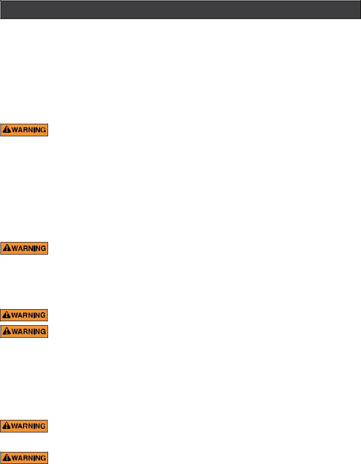
Location and Clearances
All criteria given in the following sections reflect minimum clearances. However, each installation must also be evaluated, taking into account the prevailing local conditions such as proximity and height of walls, and proximity to public access areas.
The heat pump must be placed to provide clearances on all sides for maintenance and inspection.
1.At least 24 in.[610 mm] access must be available in the front and 12 in. [30.5 mm] on all the other sides of the heat pump for service and proper air flow. (Manufacturer’s recommendation).
3
2.If the heat pump is to be installed under a cover or under a vertical overhang, the unit must have a minimum of five (5) feet [1520
mm] clearance from the top of the heat pump. |
|
(Manufacturer’s recommendation). |
|
3.Install a minimum of five (5) feet [1.52 m] from the inside wall of the pool or spa unless the heat pump is separated from the pool or spa by a five
(5)foot high solid fence or other permanent barrier. Canadian installations require a minimum of three
(3)meters from pool water.
4.Install heat pump a minimum of 6 in. [153 mm] from the wall of the house.
|
|
|
OPEN |
|
NO SPRINKLERS |
|
|
AIR FLOW OUT |
OVER HANG |
|
|
|
||
|
|
|
|
5 FT min. |
|
|
|
|
(1520 mm) |
|
|
EVAPORATOR |
|
|
|
|
COILS |
|
|
|
|
SERVICE |
|
6"min. |
|
|
|
(153 mm) |
|
|
|
ACCESS |
|
|
|
|
|
AIR |
|
|
|
24" min. |
|
|
|
|
(610 mm) |
|
FLOW |
12"min. |
12"min. |
3" |
|
IN |
|
|
|||
(305 mm) |
(305 mm) |
(76 mm) |
|
|
SLAB |
|
SLAB |
|
|
Heat Pump Location and Clearances
Anchor Clamp Installation
Installation of the anchor clamps is recommended in all installations. Installation of the anchor clamps is required in Florida (see Florida Building Code 301.13).
Anchor clamps hold the heat pump to the equipment pad in order to withstand high winds caused during extreme weather (i.e. hurricanes).
To install the anchor clamps:
1.Be sure the heat pump is in its permanent location on the equipment pad.
2.Place the clamps at the base of the heat pump in the four (4) locations, shown in the image below.
Note: Bolts and bolt anchors are not included with the heat pump. The installer must provide 1/4” x 1-3/8” stainless steel anchor bolts and the appropriate size concrete anchor to mount the clamp to the equipment pad. Be sure to check local codes.
3.Fit the hook of each clamp over the lip on the base panel of the heat pump. The hook should fit between the lip of the base panel and the evaporator coil guard.
Heat Pump |
Heat Pump |
Clamps |
Clamps |
Anchor Clamp Installation
UltraTemp® Heat Pump Installation and User’s Guide
4
Anchor Clamp Installation, Continued
4.Mark the position of the hole in each clamp on the equipment pad.
5.Use a masonry drill bit and drill a hole in the cement with a diameter as determined by the concrete anchor, at each of the marks on the equipment pad. The hole should be approximately 1½ in. deep.
6.Insert a bolt anchor into each of the holes. Be sure the anchors are set completely into the holes.
7.Position the anchor clamps so that the holes in the clamps are over the bolt anchors.
Be sure that the clamp hooks are over the lip of the heat pump base.
8.Insert an anchor bolt through each clamp into the anchor and tighten to secure the clamp and heat pump to the equipment pad.
 AIR COIL GUARD
AIR 
COIL
1-3/8" HEX BOLT (installer provided)
HEAT PUMP
ANCHOR CLAMP
HEAT PUMP
BASE
BOLT ANCHOR (installer provided)
CONCRETE
EQUIPMENT PAD
Anchor Clamp Installation
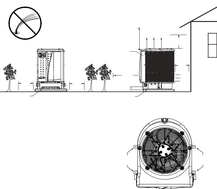
Water Connections and Plumbing
The image below shows the standard plumbing layout with a single heat pump unit. Follow the image below from right to left for the standard plumbing sequence.
Arrangement of pool system components (other than the standard plumbing image below), and the location of the heat pump (above or below the pool water surface) can affect the operation of the heat pump’s water pressure switch.
Location of the heat pump above or below the pool water surface can also affect operation of the switch.
The pressure switch can be adjusted to accommodate this effect if the heat pump water connections are no more than six (6) feet below the pool water surface.
See instructions for pressure switch adjustment on the next page. If the heat pump is installed outside of this range, an external pressure switch may need to be installed in the plumbing upstream of the heat pump.
Note: Be advised that when pool equipment is located below the pool surface a leak can result in large-scale water loss or flooding. Pentair is not responsible for such
water loss or flooding or damage.
Automatic Flow Control Valve
The inlet/outlet header of the heat pump comes equipped with an internal automatic flow control valve.
The automatic flow control valve maintains the proper flow through the heat pump at rates up to 120 gpm
(456 lpm). If the filter system flow rate is higher than 120 gpm (456 lpm), install a manual bypass valve, see image below*.
Note: Be advised that if your circulation pump is over
2 HP or if the total flow exceeds 120 gpm (456 lpm), you will have to add an external bypass valve. Excess water flow will damage the heat exchanger.
Standard Plumbing Layout
HEAT PUMP
FILTER
POOL PUMP
CHEMICAL FEEDER
OR CHLORINATOR
TO POOL OR SPA |
MANUAL BYPASS VALVE * |
FROM POOL OR SPA |
(Optional) |
|
To Pool < Chlorinator or Chemical Feeder < Heat Pump < Filter < Pump < Skimmer and Main Drain < From Pool
UltraTemp® Heat Pump Installation and User’s Guide
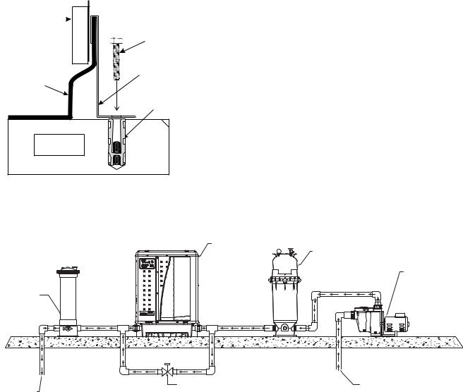
Water Connections to the Heat Pump
Two inch Quick Connect fittings have been installed on the water inlet and outlet connections. Filtered cool water is plumbed to the inlet, located on the right side of the heat pump. Heated water flows through the outlet, located on the left side of the heat pump.
Plastic piping (PVC Schedule 40) should be connected to the heat pump. The unions, provided with the unit, accept 2 in. PVC pipe.
WATER
INLET UNION
WATER
OUTLET UNION
Heat Pump Water Connections
Always be sure that flow requirements and pool water turnover rates can be maintained with the installation of additional heat pumps and plumbing restrictions.
Water Pressure Switch Adjustment
The pressure switch is preset at the factory for activation at 1.5 psi [10 kPa]. This factory setting works for most basic installations. Only adjust the water pressure switch if the heat pump does not operate when the proper flow is applied to unit or if the heat pump does not shut off when the filter pump is off.
Occasionally, unusual plumbing configurations or necessary restrictions in the plumbing may cause pressure sensing problems. In these rare situations, the plumbing system configuration may require adjustment of the water pressure switch.
Adjustment of the pressure switch may be necessary if any part of the filter system piping is 3 feet [0.91 m] or more above the top of the heat pump.
In general, if the heat pump is installed more than 6 feet [1.83 m] below the pool surface, an external water flow switch must be added to the plumbing system.
The water pressure switch should be adjusted to turn the heater off when the pump is off. Setting the switch to close at too low of a flow can damage the appliance. Adjust the
switch to turn the heater off, not on.
5
On some installations, the piping from the heat pump to the pool is very short. The back pressure could be too low to trigger the pressure switch. If this happens, install a directional fitting or elbow where the return line enters the pool. This will increase back pressure for the heat pump to operate properly. Be sure to check that the system flow is above the minimum requirement of 30 gpm (110 lpm) after the directional fitting installation.
Be sure the pool fi lter is clean before making any pressure switch adjustment: A dirty fi lter will restrict the water fl ow and the pressure switch cannot be adjusted properly.
Adjusting the Pressure Switch
The following adjustment is for installations where the heat pump is below pool water level.
1.Be sure that all valves in the system are set to allow water flow through the heat pump. Start the filter pump.
2.Set the heat pump temperature above the actual temperature to call for heat.Turn the heat Pump ON.
3.Once the heat pump is running, turn off the filter pump. The heat pump should turn off immediately.
4.If the heat pump continues to operate when the filter pump is off, then the water pressure switch needs to be adjusted.
5.Remove the heat pump’s left front panel and remove remaining right front panel.The water pressure switch is located in the water plumbing in the lower right corner of the heat pump.
6.Slowly rotate the adjustment wheel on the water pressure switch in a clockwise direction until the “LOW WATER FLOW” Alarm shows on the LCD, the Red Service LED turns ON, and the heat pump stops.
7.Check the setting of the water pressure switch by starting and stopping the filter pump and checking the control panel and operation of the heater between each flow change.
8.If the water pressure switch cannot be adjusted to accommodate the conditions listed above, an external flow switch must be added to the plumbing system to ensure that the heat pump will not operate without the proper flow through the heat exchanger.
The following adjustment is for installations where the heat pump is above pool water level.
1.Be sure that all valves in the system are set to allow water flow through the heat pump. Start the filter pump.
2.Set the heat pump temperature above the actual temperature to call for heat. Turn the heat Pump ON.
3.If the LCD shows a “LOW WATER FLOW” Alarm and Red Service LED is present then the water pressure switch needs to be adjusted.
UltraTemp® Heat Pump Installation and User’s Guide
6
Water Pressure Switch Adjustment,
Continued
4.Remove the heat pump’s left front panel and remove remaining right front panel. The water pressure switch is located in the water plumbing in the lower right corner of the heat pump.
5.Slowly rotate the adjustment wheel on the water pressure switch in a counterclockwise direction until the “LOW WATER FLOW” Alarm and Red Service LED vanish, time delay countdown will start.
6.Once the heat pump is running, turn off the filter pump. The heat pump should turn off immediately.
7.If the heat pump continues to operate when the filter pump is off, turn the adjustment wheel on the water pressure switch in a clockwise direction until the “LOW WATER FLOW” Alarm shows on the LCD, the Red Service LED turns ON, and the heat pump stops.
8.Check the setting of the water pressure switch by starting and stopping the filter pump and checking the control panel and operation of the heater between each flow change.
9.If the water pressure switch cannot be adjusted to accommodate the conditions listed above, an external flow switch must be added to the
plumbing system to ensure that the heat pump will not operate without the proper flow through the heat exchanger.
12" min.


 (305 mm)
HEATER
POOL
RETURN
|
|
SPA |
|
|
MAKE-UP |
POOL |
CHECK |
|
VALVE |
|
|
INTAKE |
|
|
|
|
|
|
SPA |
FILTER |
|
RETURN |
|
|
POOL |
|
|
DRAIN |
|
|
|
PUMP |
SPA |
SPA |
|
DRAIN |
|
|
INTAKE |
|
|
|
|
Multiple Unit Installation
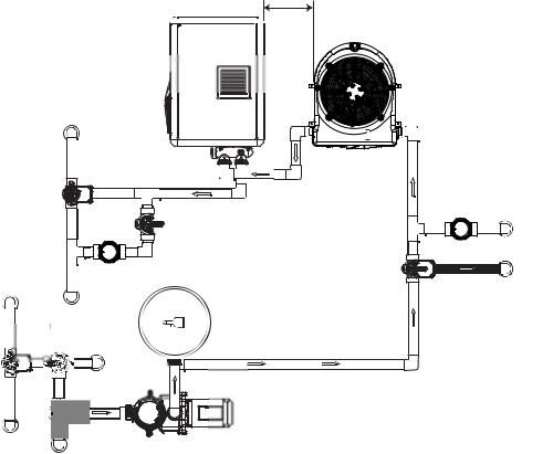
1. Heat Pump, Heater and/or Solar Combination
In certain regions of the country it may be more economical to run a heat pump during the warmer months and a gas heater during the cooler months. In some situations it may be desirable to run the heat pump in the “Chiller” mode, if so equipped, during the hottest portion of the year and a heater during the cooler months. The Pentair heat pump may be used in conjunction with a gas or electric heater or any combination of heat sources including solar. All heat sources must be plumbed in series to work correctly and efficiently.
A recommended plumbing layout for a heat pump / heater / solar combination heating system for a pool / spa combination is shown below. Your system may not contain all of these components, but the basic plumbing will apply by eliminating the component in the illustration that is not a part of your system.
2. Multiple Heat Pump Connections
All plumbing on multiple heat pump installations must be done in parallel (see image below). An equal flow of water to each heat pump is important for optimum operation.
Note: It may be necessary to adjust the water pressure switch if a unit is installed below the water level. Refer back to page 5 for details on when and how to adjust the pressure switch.
Each heat pump allows a maximum fl ow rate of 100 gpm (380 lpm) and requires a minimum of 30 gpm (110 lpm).
HEAT PUMP
CHECK
VALVE
FROMSOLAR
TO SOLAR
Multiple Unit Installation:
Heater and/or Solar Combination
UltraTemp® Heat Pump Installation and User’s Guide

Multiple Unit Installation
|
12" |
6" |
(305 mm) |
(153 mm)
24" |
|
(610 mm) |
2" PVC Pipe |
|
Extend 12" (305 mm) |
|
|
past end heater |
|
|
inlet for hydraulic |
|
|
balancing |
OPTIONAL |
|
Flow Meter |
||
2" Check Valve Bypass |
To Pool
7
Check Valves are optional on heater inlets but will help system balancing
 Extend 12" (305 mm) past end heater
inlet for hydraulic balancing
Flow Meter |
60 GPM (220 lpm) |
|
Minimum |
Pool Pump
 Minimum
2" PVC Pipe
Two Heat Pump Plumbing Layout
6" |
12" |
|
(153 mm) |
||
(305 mm) |
24" (610 mm) min. |
|
|
|
|
Check Valves are |
|
clearance for |
|
|
|
|
||
|
|
|
|
optional on heater inlets |
||
service access. |
2" PVC Pipe |
2" PVC Pipe |
|
|
||
2" PVC Pipe |
2" PVC Pipe |
but will help for system |
||||
|
||||||
|
|
|
|
|
balancing |
3" PVC Pipe 3" PVC Pipe
Extend 12" |
|
|
|
|
(305 mm) past |
|
|
|
|
end heater |
|
|
|
|
inlet for hydraulic |
Flow Meter |
3" Ball Valve Bypass |
Flow Meter |
|
balancing |
||||
|
|
To Pool
Minimum 
3" PVC Pipe
 Extend 12" (305 mm) past end heater
inlet for hydraulic balancing
120 GPM (456 lpm) Minimum
Pool Pump
Four Heat Pump Plumbing Layout
UltraTemp® Heat Pump Installation and User’s Guide
8
Electrical Connections and Wiring
RISK OF ELECTRICAL SHOCK OR ELECTROCUTION.
This heat pump contains wiring that carries high voltage. Contact with these wires could result in death or serious injury to pool or spa users, installers, or others due to electrical shock, and may also cause damage to property. Always disconnect power circuit before connecting the heat pump
Label all wires prior to disconnection when servicing controls. Wiring errors can cause improper and dangerous operation. Verify proper operation after servicing.
General Information
Wiring connections must be made exactly as shown in the wiring diagram found on the inside of the heat pump access panel; see the wiring diagrams on pages 9-11.
The heat pump must include a definite means of grounding and bonding. There is a ground lug inside the heat pump electrical compartment and a bonding lug on the left side of the heat pump.
Bonding
The National Electrical Code and most other codes require that all metallic components of a pool structure, including reinforcing steel, metal fittings, and above ground equipment be bonded together with a solid copper conductor not smaller than 8 AWG. The heat pump, along with pumps and other pool equipment must be connected to this bonding grid. A bonding lug is provided on the left side of the heat pump to ensure this requirement is met.
This heater must be connected to a bonding grid with a solid copper wire not smaller in diameter than 8 ga.
Main Power
Electrical wiring to the heat pump must be in accordance with the latest edition of the National Electric Code (NEC), ANSI/National Fire Protection Association (NFPA) 70 in the United States, and in Canada, the Canadian Electrical Code (CEC) C22.1, unless local code requirements indicate otherwise. All wiring must be done by a certified or qualified electrician.
Be sure the power to the circuit for the heat pump is turned off.
The following is the procedure to wire the heat pump to the electrical source:
1.Remove the front left panel of the heat pump cabinet, (you do not need to remove the torque head screw at the top left corner).
2.Remove the service panel to the heat pump electrical compartment. (Front left corner of unit)
3.Electrical supply lines must be run through watertight conduit. Run the wires and conduit from the power source and connect them to the conduit connection on the left side of the heat pump.
4.Connect the power leads to the bottom terminals on the main compressor contactor as shown in the wiring diagrams on pages 9-11.
5.Verify that all other contactor wires are secure; they may have loosened during shipment.
6.Connect the ground wire to the ground lug provided on the bottom of the electrical compartment.
7.Replace the service panel and reinstall screws to hold it in place.
8.Replace the front left panel.
9.Connect a copper bonding wire (8 AWG) to the bonding lug on the left side of the heat pump.
UltraTemp® Heat Pump Installation and User’s Guide
 Loading...